twentymile coal company s underground conveyance …overlandconveyor.com/pdf/twentymile coal...
TRANSCRIPT
Presented at MinExpo 2000, Las Vegas, NV, USA, October 10, 2000. All Right Reserved. Do not duplicate in whole or part without written permission from the authors.
1
Twentymile Coal Company’s Underground Conveyance System
P.K. Sollars, P.E.- Maintenance Manager, RAG Twentymile Coal Co., Oak Creek, CO E.J. Brady - Conveyance Manager, RAG Twentymile Coal Co., Oak Creek, CO
M.A. Alspaugh - Principal Systems Engineer, Overland Conveyor Co., Inc., Littleton, CO
ABSTRACT Since 1983, Twentymile Coal Company. (TCC) has operated the Foidel Creek Mine, located 24 miles southwest of Steamboat Springs, CO. Since longwall mining began at TCC in 1989, the underground conveyance system has been an important component of a highly successful mining operation that has set many production records. In June 1997, this single longwall mine produced over 1 million clean tons in a single month.
From the beginning of longwall mining at TCC, the length, lift and tonnage requirements of the conveyance system required more than standard or traditional designs offered. Therefore, the mine embraced innovative and new technology and constantly pressed suppliers to deliver more efficient and dependable equipment. This paper will document the evolution of the conveyance system as the mine progressed through the West, Southwest and East mining districts.
Particular emphasis will be given to the development and advancement of TCC’s conveyance technology realized through teamwork between the mine and key suppliers. One example is the utilization and improvement of intermediate drive technology that has impacted the entire underground longwall mining industry. Another example is the advanced computer modeling techniques created and utilized to predict the performance of critical system designs and alternatives. These models were also instrumental in developing the sophisticated control algorithms needed to interactively manage equipment during extreme operating conditions.
Over the last decade, dozens of innovations in both conveyance design and specific products have found their roots in this Northwest Colorado coal mine.
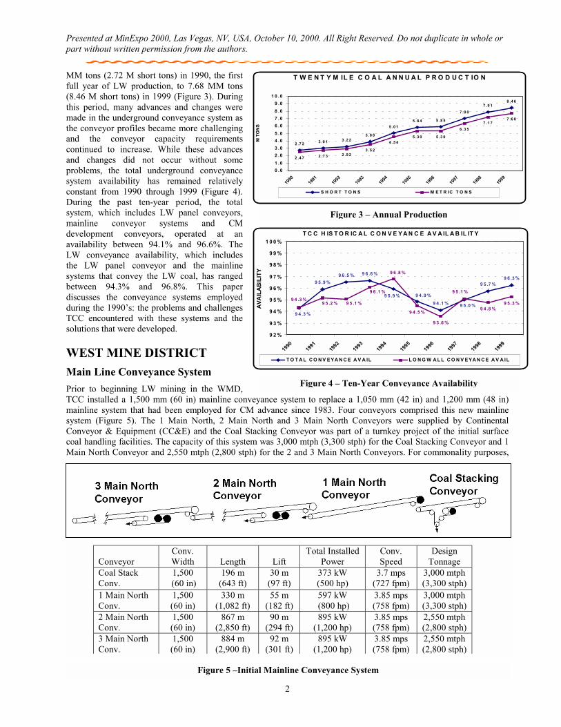
INTRODUCTION RAG’s Twentymile Coal Company (TCC) is an active underground coal mine located within the Twentymile Park Basin in Routt County, Colorado. The mine is located approximately 39 kilometers (24 miles) southwest of Steamboat Springs, Colorado (Figure 1). Two seams exist at the mine property: the Wolf Creek and Wadge Seams. Since mining began in 1983, all coal extraction has been from the Wadge Seam, which is classified as a low sulfur, high BTU group C bituminous coal. The in-place thickness of the Wadge seam ranges from 2.6 m (8.5 ft) to 3.0 m (10 ft). When mining began in 1983, Continuous Mining (CM) equipment was the single method of mining until the first Longwall (LW) equipment was installed in 1989. At times, the seam height mined by the LW can reach a minimum thickness of 2.1 m (7 ft) due to localized areas where the ash content in the bottom 0.3 m (1 ft) of coal can be excessive. The past and present mine plan is shown in Figure 2. TCC mined the LW panels in the West Mine District (WMD) from 1989 to 1994 and the three panels in the Southwest Mine District (SMD) from 1994 to 1996. Mining in the East Mine District (EMD) began in 1996 with completion expected in late 2000 or early 2001. Once this district is complete, TCC will begin mining the 12 Right Panel of the North Mine District (NMD).
Annual production from the mine has increased from 2.47
Figure 1 – Mine Location
Figure 2 – TCC Mine Plan
Presented at MinExpo 2000, Las Vegas, NV, USA, October 10, 2000. All Right Reserved. Do not duplicate in whole or part without written permission from the authors.
2
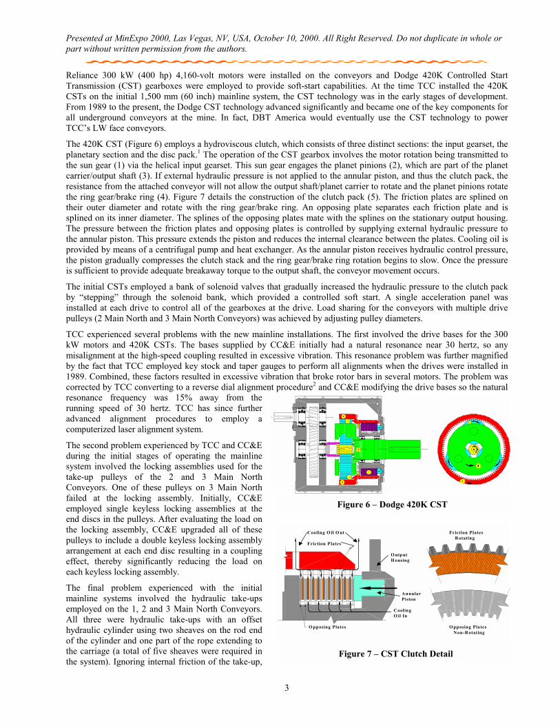
MM tons (2.72 M short tons) in 1990, the first full year of LW production, to 7.68 MM tons (8.46 M short tons) in 1999 (Figure 3). During this period, many advances and changes were made in the underground conveyance system as the conveyor profiles became more challenging and the conveyor capacity requirements continued to increase. While these advances and changes did not occur without some problems, the total underground conveyance system availability has remained relatively constant from 1990 through 1999 (Figure 4). During the past ten-year period, the total system, which includes LW panel conveyors, mainline conveyor systems and CM development conveyors, operated at an availability between 94.1% and 96.6%. The LW conveyance availability, which includes the LW panel conveyor and the mainline systems that convey the LW coal, has ranged between 94.3% and 96.8%. This paper discusses the conveyance systems employed during the 1990’s: the problems and challenges TCC encountered with these systems and the solutions that were developed.
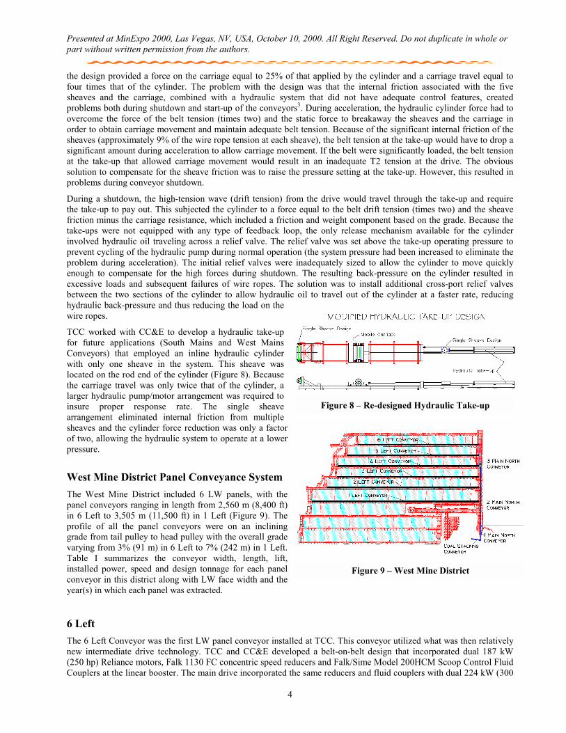
WEST MINE DISTRICT Main Line Conveyance System Prior to beginning LW mining in the WMD, TCC installed a 1,500 mm (60 in) mainline conveyance system to replace a 1,050 mm (42 in) and 1,200 mm (48 in) mainline system that had been employed for CM advance since 1983. Four conveyors comprised this new mainline system (Figure 5). The 1 Main North, 2 Main North and 3 Main North Conveyors were supplied by Continental Conveyor & Equipment (CC&E) and the Coal Stacking Conveyor was part of a turnkey project of the initial surface coal handling facilities. The capacity of this system was 3,000 mtph (3,300 stph) for the Coal Stacking Conveyor and 1 Main North Conveyor and 2,550 mtph (2,800 stph) for the 2 and 3 Main North Conveyors. For commonality purposes,
T W E N T Y M IL E C O A L A N N U A L P R O D U C T IO N
2 .7 2 3 .0 1 3 .2 23 .8 8
5 .0 15 .8 4 5 .8 5
7 .0 07 .9 1
8 .4 6
2 .4 7 2 .7 3 2 .9 23 .5 2
4 .5 45 .3 0 5 .3 0
6 .3 57 .1 7
7 .6 8
0 .01 .02 .03 .04 .05 .06 .07 .08 .09 .0
1 0 . 0
1990
1991
1992
1993
1994
1995
1996
1997
1998
1999
M T
ON
S
S H O R T T O N S M E T R IC T O N S
Figure 3 – Annual Production
T C C H IS T O R IC A L C O N V E Y A N C E A V A IL A B IL IT Y
9 5 .9 %9 6 .5 %
9 4 .1 %
9 5 .7 %9 6 .3 %
9 4 .5 %
9 3 .6 %
9 4 .8 %9 5 .3 %
9 6 .6 %
9 5 .9 % 9 4 .9 %
9 5 .0 %
9 4 .3 %
9 6 .8 %
9 5 .1 %9 4 .3 %
9 5 .2 % 9 5 .1 %
9 6 .1 %
9 2 %
9 3 %
9 4 %
9 5 %
9 6 %
9 7 %
9 8 %
9 9 %
1 0 0 %
1990
1991
1992
1993
1994
1995
1996
1997
1998
1999
AVAI
LABI
LITY
T O T A L C O N V EYA N C E A V A IL L O N G W A L L C O N V EYA N C E A V A IL
Figure 4 – Ten-Year Conveyance Availability
Figure 5 –Initial Mainline Conveyance System
Conveyor
Conv. Width
Length
Lift
Total Installed Power
Conv. Speed
Design Tonnage
Coal Stack Conv.
1,500 (60 in)
196 m (643 ft)
30 m (97 ft)
373 kW (500 hp)
3.7 mps (727 fpm)
3,000 mtph (3,300 stph)
1 Main North Conv.
1,500 (60 in)
330 m (1,082 ft)
55 m (182 ft)
597 kW (800 hp)
3.85 mps (758 fpm)
3,000 mtph (3,300 stph)
2 Main North Conv.
1,500 (60 in)
867 m (2,850 ft)
90 m (294 ft)
895 kW (1,200 hp)
3.85 mps (758 fpm)
2,550 mtph (2,800 stph)
3 Main North Conv.
1,500 (60 in)
884 m (2,900 ft)
92 m (301 ft)
895 kW (1,200 hp)
3.85 mps (758 fpm)
2,550 mtph (2,800 stph)
Presented at MinExpo 2000, Las Vegas, NV, USA, October 10, 2000. All Right Reserved. Do not duplicate in whole or part without written permission from the authors.
3
Reliance 300 kW (400 hp) 4,160-volt motors were installed on the conveyors and Dodge 420K Controlled Start Transmission (CST) gearboxes were employed to provide soft-start capabilities. At the time TCC installed the 420K CSTs on the initial 1,500 mm (60 inch) mainline system, the CST technology was in the early stages of development. From 1989 to the present, the Dodge CST technology advanced significantly and became one of the key components for all underground conveyors at the mine. In fact, DBT America would eventually use the CST technology to power TCC’s LW face conveyors.
The 420K CST (Figure 6) employs a hydroviscous clutch, which consists of three distinct sections: the input gearset, the planetary section and the disc pack.1 The operation of the CST gearbox involves the motor rotation being transmitted to the sun gear (1) via the helical input gearset. This sun gear engages the planet pinions (2), which are part of the planet carrier/output shaft (3). If external hydraulic pressure is not applied to the annular piston, and thus the clutch pack, the resistance from the attached conveyor will not allow the output shaft/planet carrier to rotate and the planet pinions rotate the ring gear/brake ring (4). Figure 7 details the construction of the clutch pack (5). The friction plates are splined on their outer diameter and rotate with the ring gear/brake ring. An opposing plate separates each friction plate and is splined on its inner diameter. The splines of the opposing plates mate with the splines on the stationary output housing. The pressure between the friction plates and opposing plates is controlled by supplying external hydraulic pressure to the annular piston. This pressure extends the piston and reduces the internal clearance between the plates. Cooling oil is provided by means of a centrifugal pump and heat exchanger. As the annular piston receives hydraulic control pressure, the piston gradually compresses the clutch stack and the ring gear/brake ring rotation begins to slow. Once the pressure is sufficient to provide adequate breakaway torque to the output shaft, the conveyor movement occurs.
The initial CSTs employed a bank of solenoid valves that gradually increased the hydraulic pressure to the clutch pack by “stepping” through the solenoid bank, which provided a controlled soft start. A single acceleration panel was installed at each drive to control all of the gearboxes at the drive. Load sharing for the conveyors with multiple drive pulleys (2 Main North and 3 Main North Conveyors) was achieved by adjusting pulley diameters.
TCC experienced several problems with the new mainline installations. The first involved the drive bases for the 300 kW motors and 420K CSTs. The bases supplied by CC&E initially had a natural resonance near 30 hertz, so any misalignment at the high-speed coupling resulted in excessive vibration. This resonance problem was further magnified by the fact that TCC employed key stock and taper gauges to perform all alignments when the drives were installed in 1989. Combined, these factors resulted in excessive vibration that broke rotor bars in several motors. The problem was corrected by TCC converting to a reverse dial alignment procedure2 and CC&E modifying the drive bases so the natural resonance frequency was 15% away from the running speed of 30 hertz. TCC has since further advanced alignment procedures to employ a computerized laser alignment system.
The second problem experienced by TCC and CC&E during the initial stages of operating the mainline system involved the locking assemblies used for the take-up pulleys of the 2 and 3 Main North Conveyors. One of these pulleys on 3 Main North failed at the locking assembly. Initially, CC&E employed single keyless locking assemblies at the end discs in the pulleys. After evaluating the load on the locking assembly, CC&E upgraded all of these pulleys to include a double keyless locking assembly arrangement at each end disc resulting in a coupling effect, thereby significantly reducing the load on each keyless locking assembly.
The final problem experienced with the initial mainline systems involved the hydraulic take-ups employed on the 1, 2 and 3 Main North Conveyors. All three were hydraulic take-ups with an offset hydraulic cylinder using two sheaves on the rod end of the cylinder and one part of the rope extending to the carriage (a total of five sheaves were required in the system). Ignoring internal friction of the take-up,
4444
2
5
1 3333
2
4444
44
33333333333333333333
11111111
2
Figure 6 – Dodge 420K CST
Cooling O il O ut Friction Plates Rotating Friction Plates O utput H ousing Annular Piston Cooling O il In O pposing Plates O pposing Plates Non-Rotating
Figure 7 – CST Clutch Detail
Presented at MinExpo 2000, Las Vegas, NV, USA, October 10, 2000. All Right Reserved. Do not duplicate in whole or part without written permission from the authors.
4
the design provided a force on the carriage equal to 25% of that applied by the cylinder and a carriage travel equal to four times that of the cylinder. The problem with the design was that the internal friction associated with the five sheaves and the carriage, combined with a hydraulic system that did not have adequate control features, created problems both during shutdown and start-up of the conveyors3. During acceleration, the hydraulic cylinder force had to overcome the force of the belt tension (times two) and the static force to breakaway the sheaves and the carriage in order to obtain carriage movement and maintain adequate belt tension. Because of the significant internal friction of the sheaves (approximately 9% of the wire rope tension at each sheave), the belt tension at the take-up would have to drop a significant amount during acceleration to allow carriage movement. If the belt were significantly loaded, the belt tension at the take-up that allowed carriage movement would result in an inadequate T2 tension at the drive. The obvious solution to compensate for the sheave friction was to raise the pressure setting at the take-up. However, this resulted in problems during conveyor shutdown.
During a shutdown, the high-tension wave (drift tension) from the drive would travel through the take-up and require the take-up to pay out. This subjected the cylinder to a force equal to the belt drift tension (times two) and the sheave friction minus the carriage resistance, which included a friction and weight component based on the grade. Because the take-ups were not equipped with any type of feedback loop, the only release mechanism available for the cylinder involved hydraulic oil traveling across a relief valve. The relief valve was set above the take-up operating pressure to prevent cycling of the hydraulic pump during normal operation (the system pressure had been increased to eliminate the problem during acceleration). The initial relief valves were inadequately sized to allow the cylinder to move quickly enough to compensate for the high forces during shutdown. The resulting back-pressure on the cylinder resulted in excessive loads and subsequent failures of wire ropes. The solution was to install additional cross-port relief valves between the two sections of the cylinder to allow hydraulic oil to travel out of the cylinder at a faster rate, reducing hydraulic back-pressure and thus reducing the load on the wire ropes.
TCC worked with CC&E to develop a hydraulic take-up for future applications (South Mains and West Mains Conveyors) that employed an inline hydraulic cylinder with only one sheave in the system. This sheave was located on the rod end of the cylinder (Figure 8). Because the carriage travel was only twice that of the cylinder, a larger hydraulic pump/motor arrangement was required to insure proper response rate. The single sheave arrangement eliminated internal friction from multiple sheaves and the cylinder force reduction was only a factor of two, allowing the hydraulic system to operate at a lower pressure.
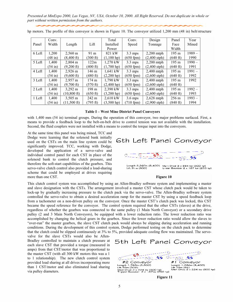
West Mine District Panel Conveyance System The West Mine District included 6 LW panels, with the panel conveyors ranging in length from 2,560 m (8,400 ft) in 6 Left to 3,505 m (11,500 ft) in 1 Left (Figure 9). The profile of all the panel conveyors were on an inclining grade from tail pulley to head pulley with the overall grade varying from 3% (91 m) in 6 Left to 7% (242 m) in 1 Left. Table I summarizes the conveyor width, length, lift, installed power, speed and design tonnage for each panel conveyor in this district along with LW face width and the year(s) in which each panel was extracted.
6 Left The 6 Left Conveyor was the first LW panel conveyor installed at TCC. This conveyor utilized what was then relatively new intermediate drive technology. TCC and CC&E developed a belt-on-belt design that incorporated dual 187 kW (250 hp) Reliance motors, Falk 1130 FC concentric speed reducers and Falk/Sime Model 200HCM Scoop Control Fluid Couplers at the linear booster. The main drive incorporated the same reducers and fluid couplers with dual 224 kW (300
Figure 8 – Re-designed Hydraulic Take-up
Figure 9 – West Mine District
Presented at MinExpo 2000, Las Vegas, NV, USA, October 10, 2000. All Right Reserved. Do not duplicate in whole or part without written permission from the authors.
5
hp motors. The profile of this conveyor is shown in Figure 10. The conveyor utilized 1,200 mm (48 in) belt/structure
with 1,400 mm (54 in) terminal groups. During the operation of this conveyor, two major problems surfaced. First, a means to provide a feedback loop to the belt-on-belt drive to control tension was not available with the installation. Second, the fluid couplers were not installed with a means to control the torque input into the conveyors.
At the same time this panel was being mined, TCC and Dodge were learning that the solenoid bank initially used on the CSTs on the main line system could be significantly improved. TCC, working with Dodge, developed the application of a servo-valve and individual control panel for each CST in place of the solenoid bank to control the clutch pressure, and therefore the soft-start capabilities of the gearbox. This servo-valve clutch control also provided a load-sharing scheme that could be employed at drives requiring more than one CST.
This clutch control system was accomplished by using an Allen-Bradley software system and implementing a master and slave designation with the CSTs. The arrangement involved a master CST whose clutch pack would be taken to lock-up by gradually increasing pressure to the clutch pack via the servo-valve. The Allen-Bradley software system controlled the servo-valve to obtain a desired acceleration ramp for the master CST by using a speed feedback loop from a tachometer on a non-driven pulley on the conveyor. Once the master CST’s clutch pack was locked, this CST became the speed reference for the conveyor. The control system required that the other CSTs (slaves) at the drive, regardless of whether the gearbox was connected to the same pulley (1 Main North Conveyor) or a secondary drive pulley (2 and 3 Main North Conveyors), be equipped with a lower reduction ratio. The lower reduction ratio was accomplished by changing the helical gears in the gearbox. Since the lower reduction ratio would allow the slaves to “over-run” the master gearbox, the slave CST clutch pack would always be slipping during acceleration and running conditions. During the development of this control system, Dodge performed testing on the clutch pack to determine that the clutch could be slipped continuously at 3% to 5%, provided adequate cooling flow was maintained. The servo-valve for the slave CSTs would also be Allen-Bradley controlled to maintain a clutch pressure at each slave CST that provided a torque (measured in amps) from that CST/motor that was proportional to the master CST (with all 300 kW motors this was a 1 to 1 relationship). The new clutch control system provided load sharing at all drives incorporating more than 1 CST/motor and also eliminated load sharing via pulley diameters.
Figure 11
Panel
Conv. Width
Length
Lift
Total Installed Power
Conv. Speed
Design Tonnage
Panel Face
Width
Year Mined
6 Left 1,200 (48 in)
2,560 m (8,400 ft)
91 m (300 ft)
821 kW (1,100 hp)
3.3 mps (650 fpm)
2,200 mtph (2,400 stph)
195 m (640 ft)
1989 –1990
5 Left 1,400 (54 in)
2,804 m (9,200 ft)
122m (400 ft)
1,270 kW (1,700 hp)
3.3 mps (650 fpm)
2,200 mtph (2,400 stph)
195 m (640 ft)
1990 –1991
4 Left 1,400 (54 in)
2,926 m (9,600 ft)
146 m (480 ft)
1,641 kW (2,200 hp)
3.3 mps (650 fpm)
2,400 mtph (2,600 stph)
195 m (640 ft)
1991 –1992
3 Left 1,400 (54 in)
2,957 m (9,700 ft)
174 m (570 ft)
1,790 kW (2,400 hp)
3.3 mps (650 fpm)
2,400 mtph (2,600 stph)
195 m (640 ft)
1992
2 Left 1,400 (54 in)
3,292 m (10,800 ft)
198 m (650 ft)
2,390 kW (3,200 hp)
3.3 mps (650 fpm)
2,400 mtph (2,600 stph)
195 m (640 ft)
1992 – 1993
1 Left 1,400 (54 in)
3,505 m (11,500 ft)
242 m (795 ft)
2,610 kW (3,500 hp)
3.6 mps (710 fpm)
2,628 mtph (2,900 stph)
256 m (840 ft)
1993 –1994
Table I – West Mine District Panel Conveyors
Figure 10
Presented at MinExpo 2000, Las Vegas, NV, USA, October 10, 2000. All Right Reserved. Do not duplicate in whole or part without written permission from the authors.
6
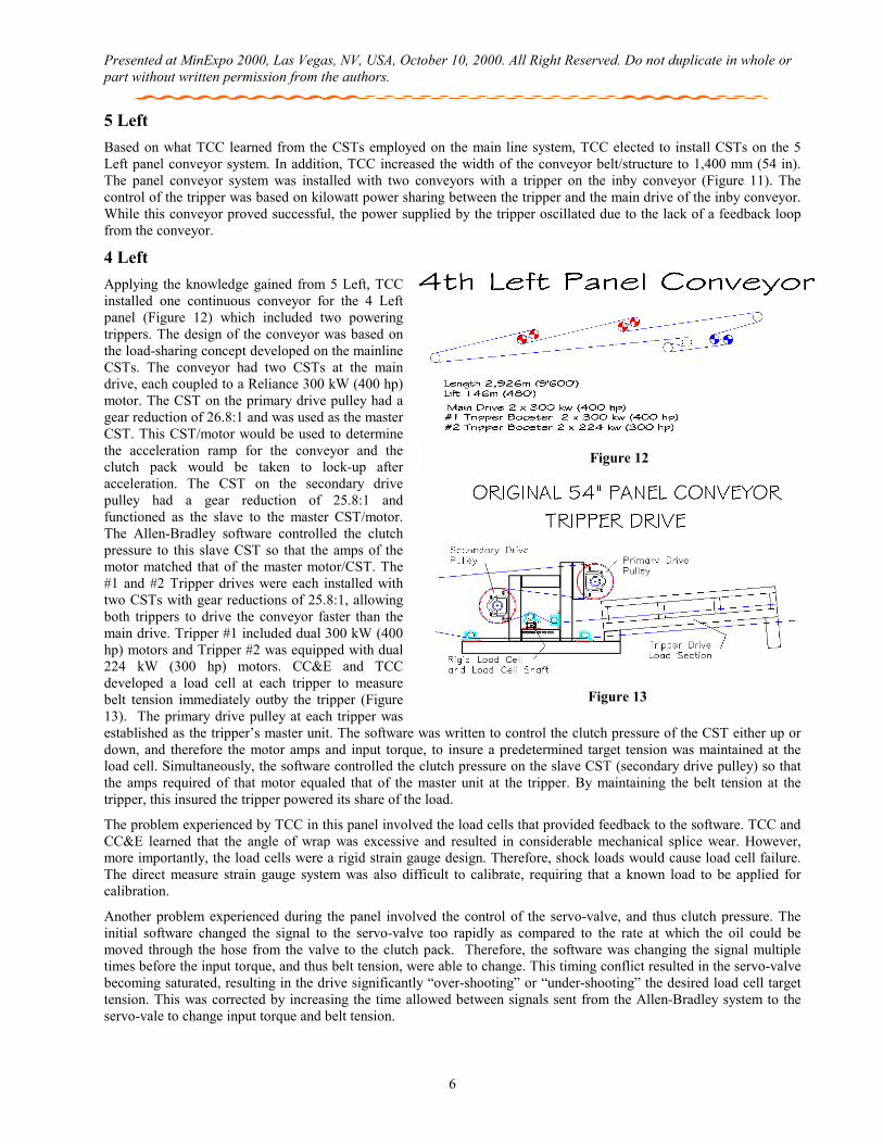
5 Left Based on what TCC learned from the CSTs employed on the main line system, TCC elected to install CSTs on the 5 Left panel conveyor system. In addition, TCC increased the width of the conveyor belt/structure to 1,400 mm (54 in). The panel conveyor system was installed with two conveyors with a tripper on the inby conveyor (Figure 11). The control of the tripper was based on kilowatt power sharing between the tripper and the main drive of the inby conveyor. While this conveyor proved successful, the power supplied by the tripper oscillated due to the lack of a feedback loop from the conveyor.
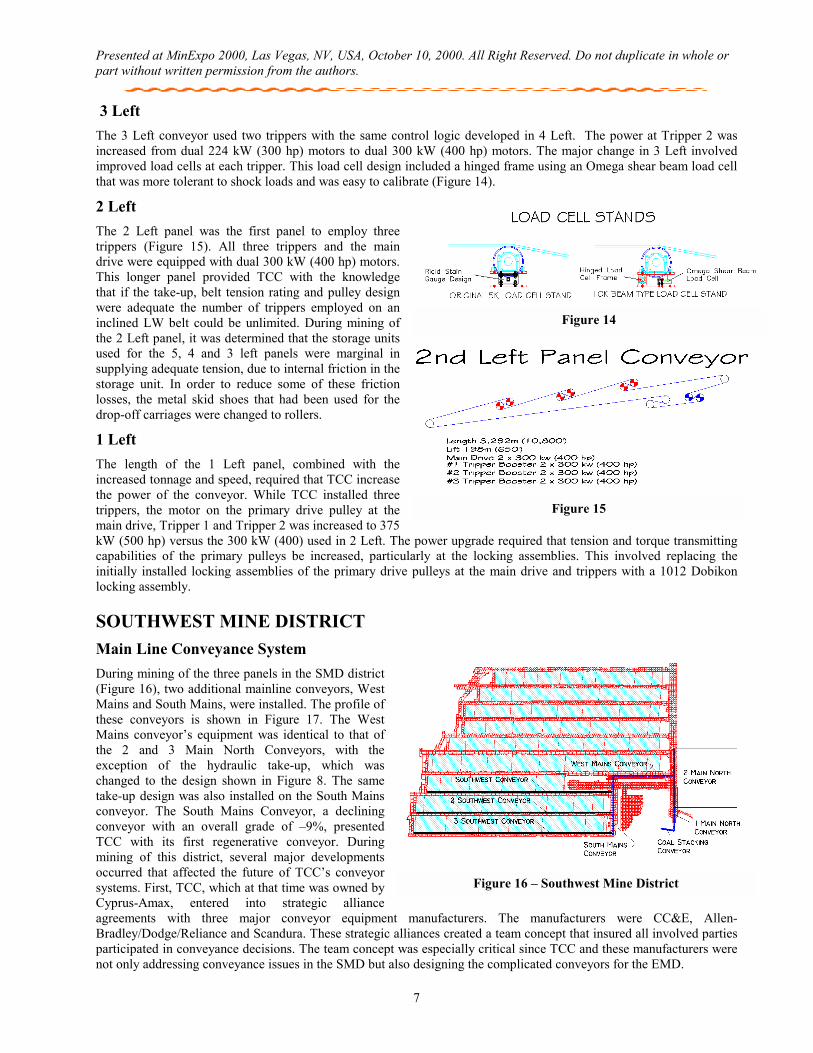
4 Left Applying the knowledge gained from 5 Left, TCC installed one continuous conveyor for the 4 Left panel (Figure 12) which included two powering trippers. The design of the conveyor was based on the load-sharing concept developed on the mainline CSTs. The conveyor had two CSTs at the main drive, each coupled to a Reliance 300 kW (400 hp) motor. The CST on the primary drive pulley had a gear reduction of 26.8:1 and was used as the master CST. This CST/motor would be used to determine the acceleration ramp for the conveyor and the clutch pack would be taken to lock-up after acceleration. The CST on the secondary drive pulley had a gear reduction of 25.8:1 and functioned as the slave to the master CST/motor. The Allen-Bradley software controlled the clutch pressure to this slave CST so that the amps of the motor matched that of the master motor/CST. The #1 and #2 Tripper drives were each installed with two CSTs with gear reductions of 25.8:1, allowing both trippers to drive the conveyor faster than the main drive. Tripper #1 included dual 300 kW (400 hp) motors and Tripper #2 was equipped with dual 224 kW (300 hp) motors. CC&E and TCC developed a load cell at each tripper to measure belt tension immediately outby the tripper (Figure 13). The primary drive pulley at each tripper was established as the tripper’s master unit. The software was written to control the clutch pressure of the CST either up or down, and therefore the motor amps and input torque, to insure a predetermined target tension was maintained at the load cell. Simultaneously, the software controlled the clutch pressure on the slave CST (secondary drive pulley) so that the amps required of that motor equaled that of the master unit at the tripper. By maintaining the belt tension at the tripper, this insured the tripper powered its share of the load.
The problem experienced by TCC in this panel involved the load cells that provided feedback to the software. TCC and CC&E learned that the angle of wrap was excessive and resulted in considerable mechanical splice wear. However, more importantly, the load cells were a rigid strain gauge design. Therefore, shock loads would cause load cell failure. The direct measure strain gauge system was also difficult to calibrate, requiring that a known load to be applied for calibration.
Another problem experienced during the panel involved the control of the servo-valve, and thus clutch pressure. The initial software changed the signal to the servo-valve too rapidly as compared to the rate at which the oil could be moved through the hose from the valve to the clutch pack. Therefore, the software was changing the signal multiple times before the input torque, and thus belt tension, were able to change. This timing conflict resulted in the servo-valve becoming saturated, resulting in the drive significantly “over-shooting” or “under-shooting” the desired load cell target tension. This was corrected by increasing the time allowed between signals sent from the Allen-Bradley system to the servo-vale to change input torque and belt tension.
Figure 13
Figure 12
Presented at MinExpo 2000, Las Vegas, NV, USA, October 10, 2000. All Right Reserved. Do not duplicate in whole or part without written permission from the authors.
7
3 Left The 3 Left conveyor used two trippers with the same control logic developed in 4 Left. The power at Tripper 2 was increased from dual 224 kW (300 hp) motors to dual 300 kW (400 hp) motors. The major change in 3 Left involved improved load cells at each tripper. This load cell design included a hinged frame using an Omega shear beam load cell that was more tolerant to shock loads and was easy to calibrate (Figure 14).
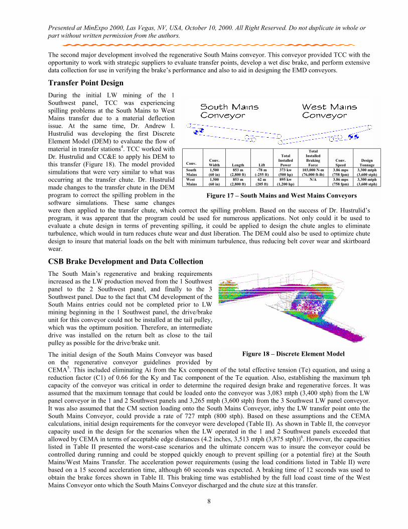
2 Left The 2 Left panel was the first panel to employ three trippers (Figure 15). All three trippers and the main drive were equipped with dual 300 kW (400 hp) motors. This longer panel provided TCC with the knowledge that if the take-up, belt tension rating and pulley design were adequate the number of trippers employed on an inclined LW belt could be unlimited. During mining of the 2 Left panel, it was determined that the storage units used for the 5, 4 and 3 left panels were marginal in supplying adequate tension, due to internal friction in the storage unit. In order to reduce some of these friction losses, the metal skid shoes that had been used for the drop-off carriages were changed to rollers.
1 Left The length of the 1 Left panel, combined with the increased tonnage and speed, required that TCC increase the power of the conveyor. While TCC installed three trippers, the motor on the primary drive pulley at the main drive, Tripper 1 and Tripper 2 was increased to 375 kW (500 hp) versus the 300 kW (400) used in 2 Left. The power upgrade required that tension and torque transmitting capabilities of the primary pulleys be increased, particularly at the locking assemblies. This involved replacing the initially installed locking assemblies of the primary drive pulleys at the main drive and trippers with a 1012 Dobikon locking assembly.
SOUTHWEST MINE DISTRICT Main Line Conveyance System During mining of the three panels in the SMD district (Figure 16), two additional mainline conveyors, West Mains and South Mains, were installed. The profile of these conveyors is shown in Figure 17. The West Mains conveyor’s equipment was identical to that of the 2 and 3 Main North Conveyors, with the exception of the hydraulic take-up, which was changed to the design shown in Figure 8. The same take-up design was also installed on the South Mains conveyor. The South Mains Conveyor, a declining conveyor with an overall grade of –9%, presented TCC with its first regenerative conveyor. During mining of this district, several major developments occurred that affected the future of TCC’s conveyor systems. First, TCC, which at that time was owned by Cyprus-Amax, entered into strategic alliance agreements with three major conveyor equipment manufacturers. The manufacturers were CC&E, Allen-Bradley/Dodge/Reliance and Scandura. These strategic alliances created a team concept that insured all involved parties participated in conveyance decisions. The team concept was especially critical since TCC and these manufacturers were not only addressing conveyance issues in the SMD but also designing the complicated conveyors for the EMD.
Figure 15
Figure 14
Figure 16 – Southwest Mine District
Presented at MinExpo 2000, Las Vegas, NV, USA, October 10, 2000. All Right Reserved. Do not duplicate in whole or part without written permission from the authors.
8
The second major development involved the regenerative South Mains conveyor. This conveyor provided TCC with the opportunity to work with strategic suppliers to evaluate transfer points, develop a wet disc brake, and perform extensive data collection for use in verifying the brake’s performance and also to aid in designing the EMD conveyors.
Transfer Point Design During the initial LW mining of the 1 Southwest panel, TCC was experiencing spilling problems at the South Mains to West Mains transfer due to a material deflection issue. At the same time, Dr. Andrew I. Hustrulid was developing the first Discrete Element Model (DEM) to evaluate the flow of material in transfer stations4. TCC worked with Dr. Hustrulid and CC&E to apply his DEM to this transfer (Figure 18). The model provided simulations that were very similar to what was occurring at the transfer chute. Dr. Hustrulid made changes to the transfer chute in the DEM program to correct the spilling problem in the software simulations. These same changes were then applied to the transfer chute, which correct the spilling problem. Based on the success of Dr. Hustrulid’s program, it was apparent that the program could be used for numerous applications. Not only could it be used to evaluate a chute design in terms of preventing spilling, it could be applied to design the chute angles to eliminate turbulence, which would in turn reduces chute wear and dust liberation. The DEM could also be used to optimize chute design to insure that material loads on the belt with minimum turbulence, thus reducing belt cover wear and skirtboard wear.
CSB Brake Development and Data Collection The South Main’s regenerative and braking requirements increased as the LW production moved from the 1 Southwest panel to the 2 Southwest panel, and finally to the 3 Southwest panel. Due to the fact that CM development of the South Mains entries could not be completed prior to LW mining beginning in the 1 Southwest panel, the drive/brake unit for this conveyor could not be installed at the tail pulley, which was the optimum position. Therefore, an intermediate drive was installed on the return belt as close to the tail pulley as possible for the drive/brake unit.
The initial design of the South Mains Conveyor was based on the regenerative conveyor guidelines provided by CEMA5. This included eliminating Ai from the Kx component of the total effective tension (Te) equation, and using a reduction factor (C1) of 0.66 for the Ky and Tac component of the Te equation. Also, establishing the maximum tph capacity of the conveyor was critical in order to determine the required design brake and regenerative forces. It was assumed that the maximum tonnage that could be loaded onto the conveyor was 3,083 mtph (3,400 stph) from the LW panel conveyor in the 1 and 2 Southwest panels and 3,265 mtph (3,600 stph) from the 3 Southwest LW panel conveyor. It was also assumed that the CM section loading onto the South Mains Conveyor, inby the LW transfer point onto the South Mains Conveyor, could provide a rate of 727 mtph (800 stph). Based on these assumptions and the CEMA calculations, initial design requirements for the conveyor were developed (Table II). As shown in Table II, the conveyor capacity used in the design for the scenarios when the LW operated in the 1 and 2 Southwest panels exceeded that allowed by CEMA in terms of acceptable edge distances (4.2 inches, 3,513 mtph (3,875 stph))6. However, the capacities listed in Table II presented the worst-case scenarios and the ultimate concern was to insure the conveyor could be controlled during running and could be stopped quickly enough to prevent spilling (or a potential fire) at the South Mains/West Mains Transfer. The acceleration power requirements (using the load conditions listed in Table II) were based on a 15 second acceleration time, although 60 seconds was expected. A braking time of 12 seconds was used to obtain the brake forces shown in Table II. This braking time was established by the full load coast time of the West Mains Conveyor onto which the South Mains Conveyor discharged and the chute size at this transfer.
Figure 18 – Discrete Element Model
Conv.
Conv. Width
Length
Lift
Total
Installed Power
Total Installed Braking
Force
Conv. Speed
Design Tonnage
South Mains
1,500 (60 in)
853 m (2,800 ft)
-78 m (-255 ft)
373 kw (500 hp)
103,000 N-m (76,000 ft-lb)
3.86 mps (758 fpm)
3,300 mtph (3,600 stph)
West Mains
1,500 (60 in)
853 m (2,800 ft)
62 m (205 ft)
895 kw (1,200 hp)
N/A 3.86 mps (758 fpm)
3,300 mtph (3,600 stph)
Figure 17 – South Mains and West Mains Conveyors
Presented at MinExpo 2000, Las Vegas, NV, USA, October 10, 2000. All Right Reserved. Do not duplicate in whole or part without written permission from the authors.
9
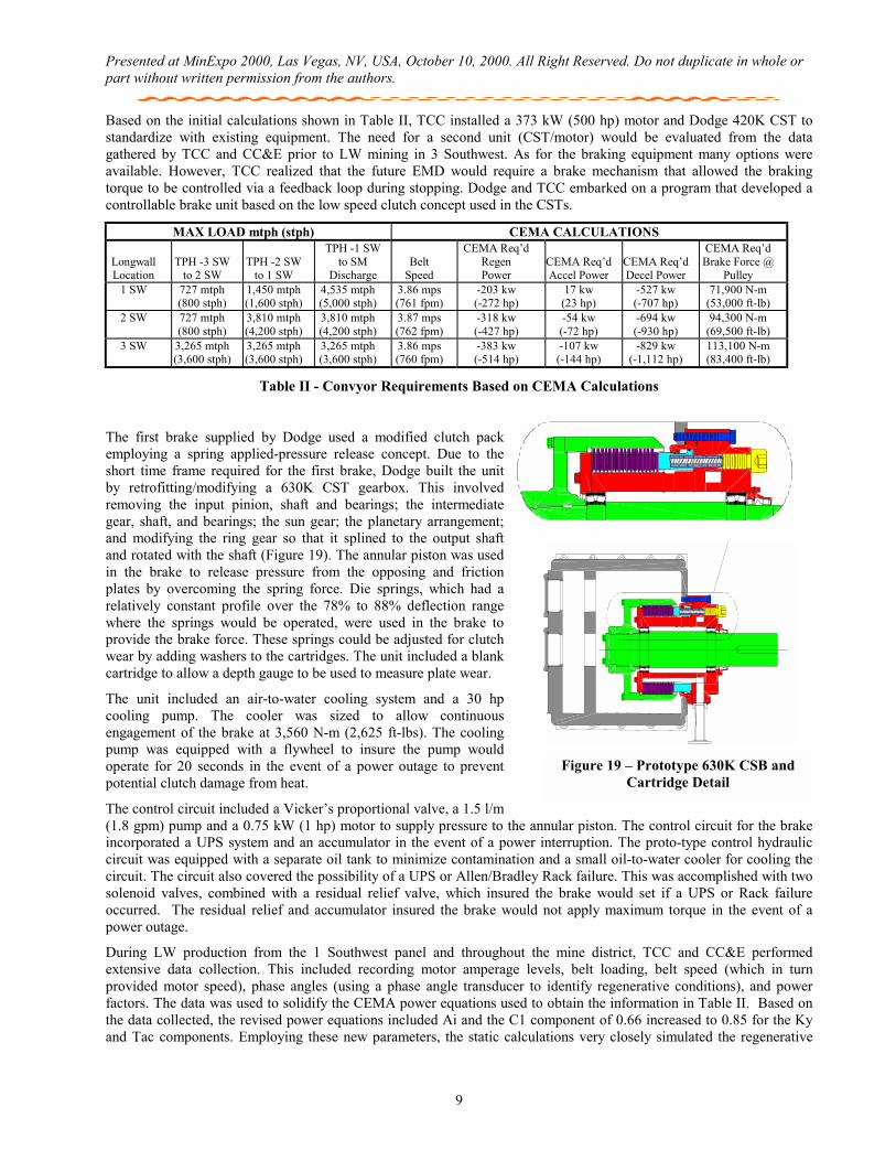
Based on the initial calculations shown in Table II, TCC installed a 373 kW (500 hp) motor and Dodge 420K CST to standardize with existing equipment. The need for a second unit (CST/motor) would be evaluated from the data gathered by TCC and CC&E prior to LW mining in 3 Southwest. As for the braking equipment many options were available. However, TCC realized that the future EMD would require a brake mechanism that allowed the braking torque to be controlled via a feedback loop during stopping. Dodge and TCC embarked on a program that developed a controllable brake unit based on the low speed clutch concept used in the CSTs.
MAX LOAD mtph (stph) CEMA CALCULATIONS
Longwall Location
TPH -3 SW
to 2 SW
TPH -2 SW
to 1 SW
TPH -1 SW to SM
Discharge
Belt
Speed
CEMA Req’d Regen Power
CEMA Req’d Accel Power
CEMA Req’d Decel Power
CEMA Req’d Brake Force @
Pulley 1 SW 727 mtph
(800 stph) 1,450 mtph (1,600 stph)
4,535 mtph (5,000 stph)
3.86 mps (761 fpm)
-203 kw (-272 hp)
17 kw (23 hp)
-527 kw (-707 hp)
71,900 N-m (53,000 ft-lb)
2 SW 727 mtph (800 stph)
3,810 mtph (4,200 stph)
3,810 mtph (4,200 stph)
3.87 mps (762 fpm)
-318 kw (-427 hp)
-54 kw (-72 hp)
-694 kw (-930 hp)
94,300 N-m (69,500 ft-lb)
3 SW 3,265 mtph (3,600 stph)
3,265 mtph (3,600 stph)
3,265 mtph (3,600 stph)
3.86 mps (760 fpm)
-383 kw (-514 hp)
-107 kw (-144 hp)
-829 kw (-1,112 hp)
113,100 N-m (83,400 ft-lb)
Table II - Convyor Requirements Based on CEMA Calculations
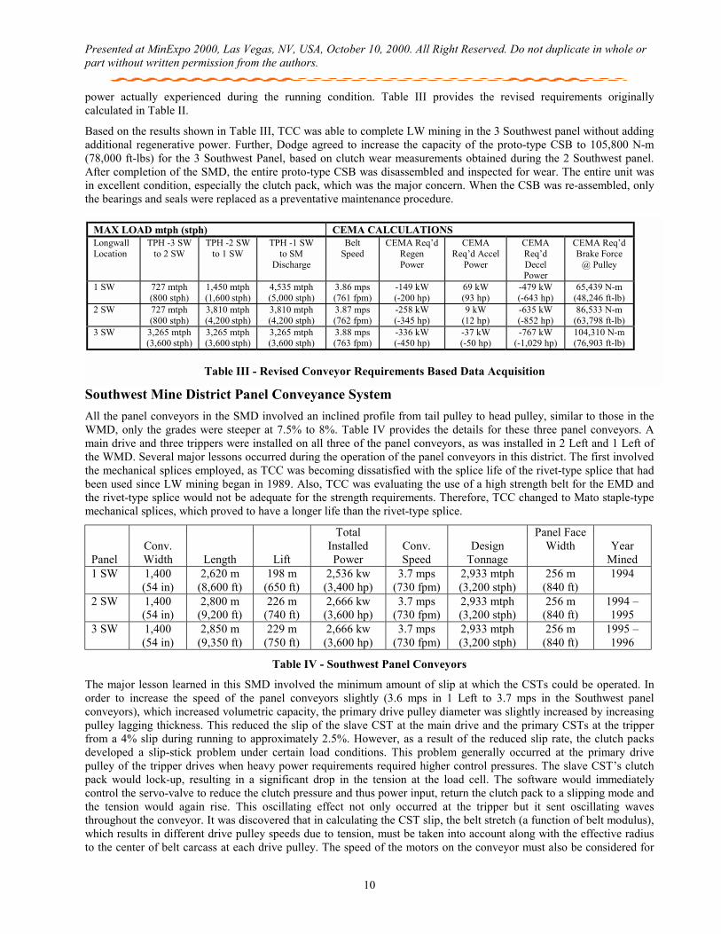
The first brake supplied by Dodge used a modified clutch pack employing a spring applied-pressure release concept. Due to the short time frame required for the first brake, Dodge built the unit by retrofitting/modifying a 630K CST gearbox. This involved removing the input pinion, shaft and bearings; the intermediate gear, shaft, and bearings; the sun gear; the planetary arrangement; and modifying the ring gear so that it splined to the output shaft and rotated with the shaft (Figure 19). The annular piston was used in the brake to release pressure from the opposing and friction plates by overcoming the spring force. Die springs, which had a relatively constant profile over the 78% to 88% deflection range where the springs would be operated, were used in the brake to provide the brake force. These springs could be adjusted for clutch wear by adding washers to the cartridges. The unit included a blank cartridge to allow a depth gauge to be used to measure plate wear.
The unit included an air-to-water cooling system and a 30 hp cooling pump. The cooler was sized to allow continuous engagement of the brake at 3,560 N-m (2,625 ft-lbs). The cooling pump was equipped with a flywheel to insure the pump would operate for 20 seconds in the event of a power outage to prevent potential clutch damage from heat.
The control circuit included a Vicker’s proportional valve, a 1.5 l/m (1.8 gpm) pump and a 0.75 kW (1 hp) motor to supply pressure to the annular piston. The control circuit for the brake incorporated a UPS system and an accumulator in the event of a power interruption. The proto-type control hydraulic circuit was equipped with a separate oil tank to minimize contamination and a small oil-to-water cooler for cooling the circuit. The circuit also covered the possibility of a UPS or Allen/Bradley Rack failure. This was accomplished with two solenoid valves, combined with a residual relief valve, which insured the brake would set if a UPS or Rack failure occurred. The residual relief and accumulator insured the brake would not apply maximum torque in the event of a power outage.
During LW production from the 1 Southwest panel and throughout the mine district, TCC and CC&E performed extensive data collection. This included recording motor amperage levels, belt loading, belt speed (which in turn provided motor speed), phase angles (using a phase angle transducer to identify regenerative conditions), and power factors. The data was used to solidify the CEMA power equations used to obtain the information in Table II. Based on the data collected, the revised power equations included Ai and the C1 component of 0.66 increased to 0.85 for the Ky and Tac components. Employing these new parameters, the static calculations very closely simulated the regenerative
Figure 19 – Prototype 630K CSB and Cartridge Detail
Presented at MinExpo 2000, Las Vegas, NV, USA, October 10, 2000. All Right Reserved. Do not duplicate in whole or part without written permission from the authors.
10
power actually experienced during the running condition. Table III provides the revised requirements originally calculated in Table II.
Based on the results shown in Table III, TCC was able to complete LW mining in the 3 Southwest panel without adding additional regenerative power. Further, Dodge agreed to increase the capacity of the proto-type CSB to 105,800 N-m (78,000 ft-lbs) for the 3 Southwest Panel, based on clutch wear measurements obtained during the 2 Southwest panel. After completion of the SMD, the entire proto-type CSB was disassembled and inspected for wear. The entire unit was in excellent condition, especially the clutch pack, which was the major concern. When the CSB was re-assembled, only the bearings and seals were replaced as a preventative maintenance procedure.
Southwest Mine District Panel Conveyance System All the panel conveyors in the SMD involved an inclined profile from tail pulley to head pulley, similar to those in the WMD, only the grades were steeper at 7.5% to 8%. Table IV provides the details for these three panel conveyors. A main drive and three trippers were installed on all three of the panel conveyors, as was installed in 2 Left and 1 Left of the WMD. Several major lessons occurred during the operation of the panel conveyors in this district. The first involved the mechanical splices employed, as TCC was becoming dissatisfied with the splice life of the rivet-type splice that had been used since LW mining began in 1989. Also, TCC was evaluating the use of a high strength belt for the EMD and the rivet-type splice would not be adequate for the strength requirements. Therefore, TCC changed to Mato staple-type mechanical splices, which proved to have a longer life than the rivet-type splice.
Panel
Conv. Width
Length
Lift
Total Installed Power
Conv. Speed
Design
Tonnage
Panel Face Width
Year
Mined 1 SW 1,400
(54 in) 2,620 m
(8,600 ft) 198 m
(650 ft) 2,536 kw (3,400 hp)
3.7 mps (730 fpm)
2,933 mtph (3,200 stph)
256 m (840 ft)
1994
2 SW 1,400 (54 in)
2,800 m (9,200 ft)
226 m (740 ft)
2,666 kw (3,600 hp)
3.7 mps (730 fpm)
2,933 mtph (3,200 stph)
256 m (840 ft)
1994 –1995
3 SW 1,400 (54 in)
2,850 m (9,350 ft)
229 m (750 ft)
2,666 kw (3,600 hp)
3.7 mps (730 fpm)
2,933 mtph (3,200 stph)
256 m (840 ft)
1995 –1996
Table IV - Southwest Panel Conveyors
The major lesson learned in this SMD involved the minimum amount of slip at which the CSTs could be operated. In order to increase the speed of the panel conveyors slightly (3.6 mps in 1 Left to 3.7 mps in the Southwest panel conveyors), which increased volumetric capacity, the primary drive pulley diameter was slightly increased by increasing pulley lagging thickness. This reduced the slip of the slave CST at the main drive and the primary CSTs at the tripper from a 4% slip during running to approximately 2.5%. However, as a result of the reduced slip rate, the clutch packs developed a slip-stick problem under certain load conditions. This problem generally occurred at the primary drive pulley of the tripper drives when heavy power requirements required higher control pressures. The slave CST’s clutch pack would lock-up, resulting in a significant drop in the tension at the load cell. The software would immediately control the servo-valve to reduce the clutch pressure and thus power input, return the clutch pack to a slipping mode and the tension would again rise. This oscillating effect not only occurred at the tripper but it sent oscillating waves throughout the conveyor. It was discovered that in calculating the CST slip, the belt stretch (a function of belt modulus), which results in different drive pulley speeds due to tension, must be taken into account along with the effective radius to the center of belt carcass at each drive pulley. The speed of the motors on the conveyor must also be considered for
MAX LOAD mtph (stph) CEMA CALCULATIONS Longwall Location
TPH -3 SW to 2 SW
TPH -2 SW to 1 SW
TPH -1 SW to SM
Discharge
Belt Speed
CEMA Req’d Regen Power
CEMA Req’d Accel
Power
CEMA Req’d Decel Power
CEMA Req’d Brake Force
@ Pulley
1 SW 727 mtph (800 stph)
1,450 mtph (1,600 stph)
4,535 mtph (5,000 stph)
3.86 mps (761 fpm)
-149 kW (-200 hp)
69 kW (93 hp)
-479 kW (-643 hp)
65,439 N-m (48,246 ft-lb)
2 SW 727 mtph (800 stph)
3,810 mtph (4,200 stph)
3,810 mtph (4,200 stph)
3.87 mps (762 fpm)
-258 kW (-345 hp)
9 kW (12 hp)
-635 kW (-852 hp)
86,533 N-m (63,798 ft-lb)
3 SW 3,265 mtph (3,600 stph)
3,265 mtph (3,600 stph)
3,265 mtph (3,600 stph)
3.88 mps (763 fpm)
-336 kW (-450 hp)
-37 kW (-50 hp)
-767 kW (-1,029 hp)
104,310 N-m (76,903 ft-lb)
Table III - Revised Conveyor Requirements Based Data Acquisition
Presented at MinExpo 2000, Las Vegas, NV, USA, October 10, 2000. All Right Reserved. Do not duplicate in whole or part without written permission from the authors.
11
different loads on the flights of the conveyor when calculating slip ratios. The power factor at each motor can also affect the motor speed and needs to be regulated. TCC learned that each conveyor must be closely evaluated when considering any change to the conveyor that could affect the speed of drive pulleys.
EAST MINE DISTRICT Mainline Conveyance System When TCC moved from the SMD to the EMD, new LW equipment was purchased with significantly higher production capacity. This required an upgrade of the mainline conveyors and the panel conveyors. After evaluating the surge capacity of the new LW equipment, it was decided that the mainline system should be capable of handling 4,583 mtph (5,000 stph) continuously and surges of 5,316 mtph (5,800 stph), due to CM coal. TCC initially evaluated installing either a 1,800 mm (72 in) or a 2,150 mm (84 in) mainline system. However, both options would have required that the mine be shutdown for a considerable time to install the new mainline system because, due to ventilation, the only entry available would be the entry currently used for the 1,500 mm (60 in) system. Furthermore, the cost of these options was excessive when compared to the cost associated with upgrading the existing mainline system to handle 4,583 mtph (5,000 stph). Since all of the equipment used in the EMD panels would be new equipment, the conveyance equipment used in the WMD and SMD would be available to upgrade the mainline system. Therefore, it was decided that the larger mainline system would be postponed until later in the EMD.
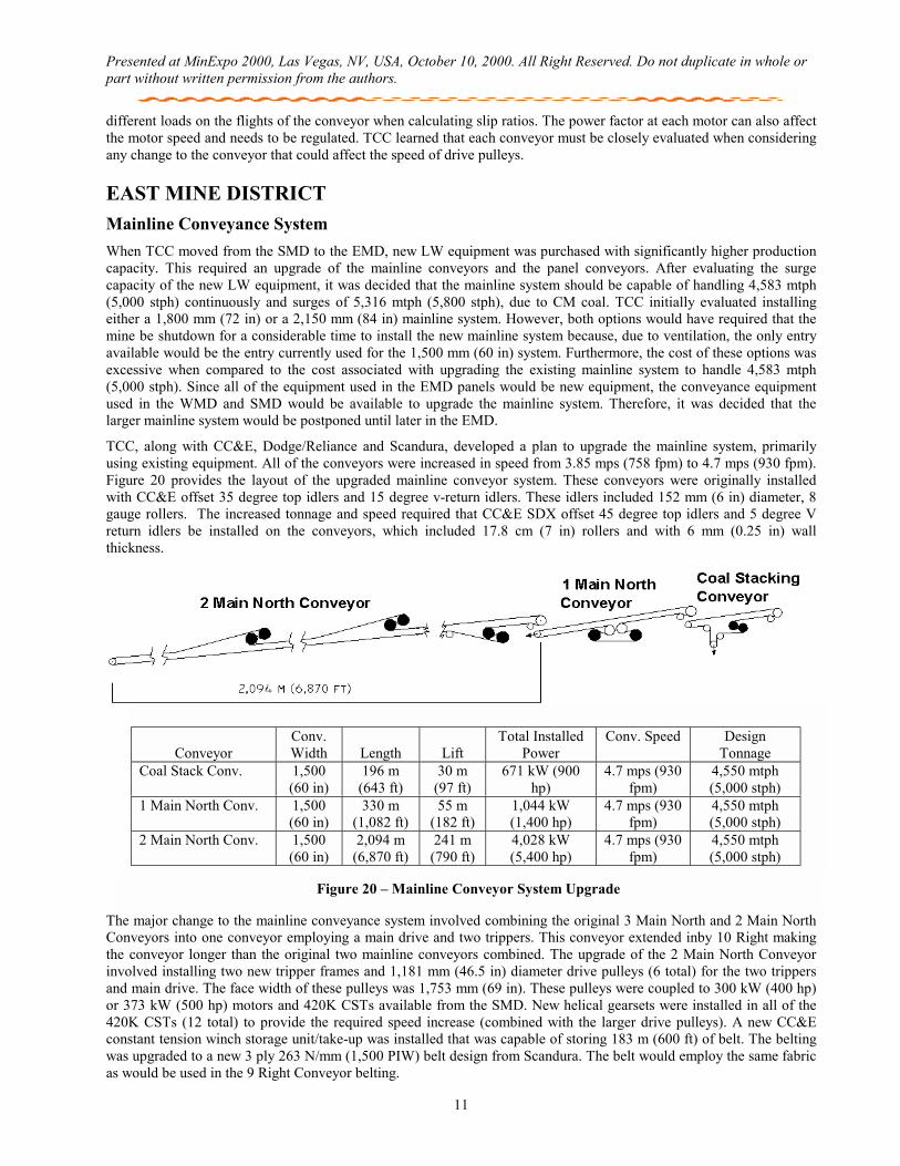
TCC, along with CC&E, Dodge/Reliance and Scandura, developed a plan to upgrade the mainline system, primarily using existing equipment. All of the conveyors were increased in speed from 3.85 mps (758 fpm) to 4.7 mps (930 fpm). Figure 20 provides the layout of the upgraded mainline conveyor system. These conveyors were originally installed with CC&E offset 35 degree top idlers and 15 degree v-return idlers. These idlers included 152 mm (6 in) diameter, 8 gauge rollers. The increased tonnage and speed required that CC&E SDX offset 45 degree top idlers and 5 degree V return idlers be installed on the conveyors, which included 17.8 cm (7 in) rollers and with 6 mm (0.25 in) wall thickness.
The major change to the mainline conveyance system involved combining the original 3 Main North and 2 Main North Conveyors into one conveyor employing a main drive and two trippers. This conveyor extended inby 10 Right making the conveyor longer than the original two mainline conveyors combined. The upgrade of the 2 Main North Conveyor involved installing two new tripper frames and 1,181 mm (46.5 in) diameter drive pulleys (6 total) for the two trippers and main drive. The face width of these pulleys was 1,753 mm (69 in). These pulleys were coupled to 300 kW (400 hp) or 373 kW (500 hp) motors and 420K CSTs available from the SMD. New helical gearsets were installed in all of the 420K CSTs (12 total) to provide the required speed increase (combined with the larger drive pulleys). A new CC&E constant tension winch storage unit/take-up was installed that was capable of storing 183 m (600 ft) of belt. The belting was upgraded to a new 3 ply 263 N/mm (1,500 PIW) belt design from Scandura. The belt would employ the same fabric as would be used in the 9 Right Conveyor belting.
Figure 20 – Mainline Conveyor System Upgrade
Conveyor Conv. Width
Length
Lift
Total Installed Power
Conv. Speed Design Tonnage
Coal Stack Conv. 1,500 (60 in)
196 m (643 ft)
30 m (97 ft)
671 kW (900 hp)
4.7 mps (930 fpm)
4,550 mtph (5,000 stph)
1 Main North Conv. 1,500 (60 in)
330 m (1,082 ft)
55 m (182 ft)
1,044 kW (1,400 hp)
4.7 mps (930 fpm)
4,550 mtph (5,000 stph)
2 Main North Conv. 1,500 (60 in)
2,094 m (6,870 ft)
241 m (790 ft)
4,028 kW (5,400 hp)
4.7 mps (930 fpm)
4,550 mtph (5,000 stph)
Presented at MinExpo 2000, Las Vegas, NV, USA, October 10, 2000. All Right Reserved. Do not duplicate in whole or part without written permission from the authors.
12
The 1 Main North Conveyor upgrade involved moving the drive from the head pulley to an intermediate location. This decision was based on the 1,044 kW (1,400 hp) power requirement of the upgraded conveyor that would allow three existing motor/CST units to be used with a dual pulley drive versus purchasing two new power units and a new head pulley. Moving the drive also allowed the existing take-up to be re-used while the head pulley drive option would have required a new or modified take-up. Finally, the intermediate drive would significantly improve maintenance access to the drive compared to the head pulley drive arrangement.
The equipment purchased for the 1 Main North upgrade involved a CC&E four-pulley drive frame that allowed both drive pulleys to drive the clean side of the belt. The two new drive pulleys were Dodge 1,181 mm (46.5 in) diameter, 1,753 mm (69 in) face width pulleys. All other pulleys required for the conveyor upgrade (head pulley, discharge snub pulley, high tension snub and low tension drive snub pulleys) were obtained from the West Mains and South Mains Conveyors. The belting required for this conveyor was obtained from the West Mains Conveyor which was a Scandura 5 ply 210 N/mm (1,200 piw) belt which had only been used to convey approximately 7.3 MM tons (8 M short tons) from the SMD. The tail take-up originally installed on the conveyor was adequate for the intermediate drive upgrade requirements.
The upgrade of the Coal Stacking Conveyor involved minor structural modifications to the drive building and the installation of a second drive pulley. The drive pulley and the power unit required for this upgrade were available from the SMD. Belting for this conveyor was also available from the West Mains Conveyor.
Two major problems occurred with this mainline system upgrade. First, scraper life was significantly reduced due to increased belt speed. TCC originally employed a single blade design but due to excessive blade wear, the scrapers were changing to Classic multi-blade scrapers. The second problem involved the differential coast time between the 1 and 2 Main North Conveyors. If the 1 Main North Conveyor was heavily loaded and the 2 Main North Conveyor was loaded heavy only near the discharge, a shutdown of both conveyors resulted in spills at the transfer due to the longer coast time of the 2 Main North Conveyor. The problem was resolved by installing blocking valves on the Coal Stacking and 1 Main North Conveyors. The blocking valves were controlled via software based on motor amperage levels at the time of shutdown. If the amperage was above pre-set levels, the blocking valves would be de-energized to retain the hydraulic pressure in the clutch pack, thereby insuring the inertia of the motors was transferred to the conveyor and increasing the coast time of the conveyors.
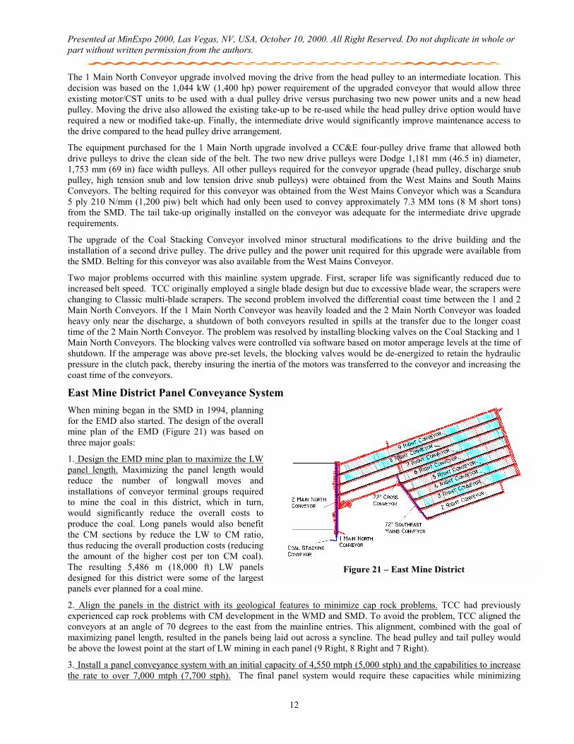
East Mine District Panel Conveyance System When mining began in the SMD in 1994, planning for the EMD also started. The design of the overall mine plan of the EMD (Figure 21) was based on three major goals:
1. Design the EMD mine plan to maximize the LW panel length. Maximizing the panel length would reduce the number of longwall moves and installations of conveyor terminal groups required to mine the coal in this district, which in turn, would significantly reduce the overall costs to produce the coal. Long panels would also benefit the CM sections by reduce the LW to CM ratio, thus reducing the overall production costs (reducing the amount of the higher cost per ton CM coal). The resulting 5,486 m (18,000 ft) LW panels designed for this district were some of the largest panels ever planned for a coal mine.
2. Align the panels in the district with its geological features to minimize cap rock problems. TCC had previously experienced cap rock problems with CM development in the WMD and SMD. To avoid the problem, TCC aligned the conveyors at an angle of 70 degrees to the east from the mainline entries. This alignment, combined with the goal of maximizing panel length, resulted in the panels being laid out across a syncline. The head pulley and tail pulley would be above the lowest point at the start of LW mining in each panel (9 Right, 8 Right and 7 Right).
3. Install a panel conveyance system with an initial capacity of 4,550 mtph (5,000 stph) and the capabilities to increase the rate to over 7,000 mtph (7,700 stph). The final panel system would require these capacities while minimizing
Figure 21 – East Mine District
Presented at MinExpo 2000, Las Vegas, NV, USA, October 10, 2000. All Right Reserved. Do not duplicate in whole or part without written permission from the authors.
13
Starting
Stopping
Running
Figure 23 – 9 Right Static Modeling
capital expenditure, installation costs and operating costs. The system also needed to minimize tripper installation as TCC’s history had shown that each additional tripper on a panel conveyor would reduce the conveyor availability by approximately 0.2% to 0.5%.
The profile and length requirements of the first two goals, combined with the requirements of the third goal, presented a significant challenge to TCC and it’s vendors. A key decision of the panel conveyance system involved selecting the conveyor size, as it would effect the design of the equipment that CC&E, Dodge/Reliance and Scandura would be required to supply. Many static analysis models were developed to evaluate the effect of different conveyor sizes. Based on the results of these models, TCC and its vendors evaluated the equipment requirements from a technology standpoint (did the equipment exist or would the equipment have to be developed?) and also from the standpoint of capital expenditure, installation costs and operating costs.
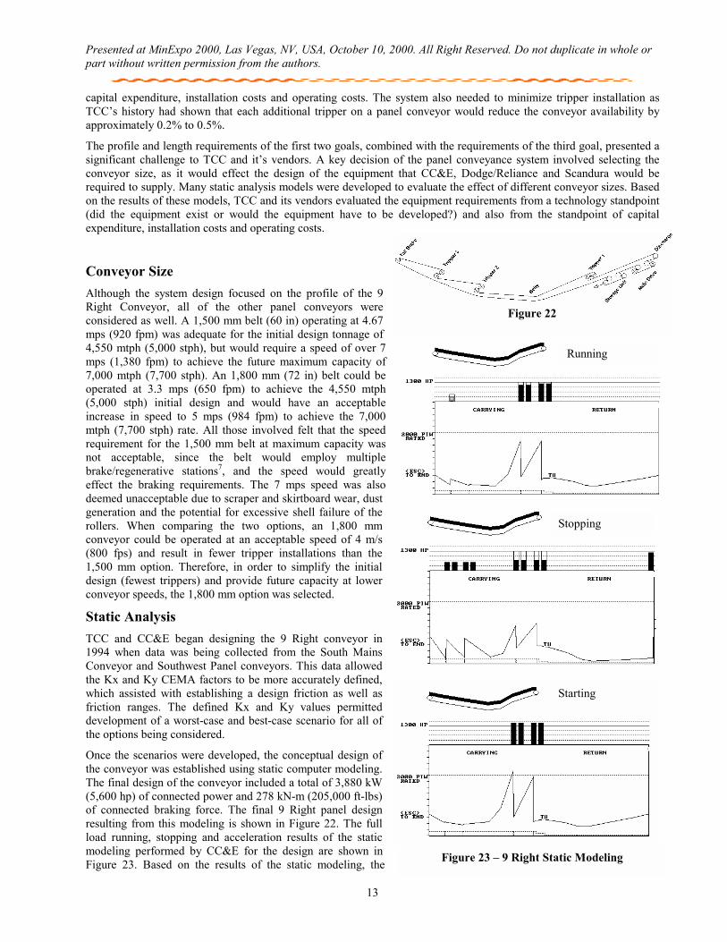
Conveyor Size Although the system design focused on the profile of the 9 Right Conveyor, all of the other panel conveyors were considered as well. A 1,500 mm belt (60 in) operating at 4.67 mps (920 fpm) was adequate for the initial design tonnage of 4,550 mtph (5,000 stph), but would require a speed of over 7 mps (1,380 fpm) to achieve the future maximum capacity of 7,000 mtph (7,700 stph). An 1,800 mm (72 in) belt could be operated at 3.3 mps (650 fpm) to achieve the 4,550 mtph (5,000 stph) initial design and would have an acceptable increase in speed to 5 mps (984 fpm) to achieve the 7,000 mtph (7,700 stph) rate. All those involved felt that the speed requirement for the 1,500 mm belt at maximum capacity was not acceptable, since the belt would employ multiple brake/regenerative stations7, and the speed would greatly effect the braking requirements. The 7 mps speed was also deemed unacceptable due to scraper and skirtboard wear, dust generation and the potential for excessive shell failure of the rollers. When comparing the two options, an 1,800 mm conveyor could be operated at an acceptable speed of 4 m/s (800 fps) and result in fewer tripper installations than the 1,500 mm option. Therefore, in order to simplify the initial design (fewest trippers) and provide future capacity at lower conveyor speeds, the 1,800 mm option was selected.
Static Analysis TCC and CC&E began designing the 9 Right conveyor in 1994 when data was being collected from the South Mains Conveyor and Southwest Panel conveyors. This data allowed the Kx and Ky CEMA factors to be more accurately defined, which assisted with establishing a design friction as well as friction ranges. The defined Kx and Ky values permitted development of a worst-case and best-case scenario for all of the options being considered.
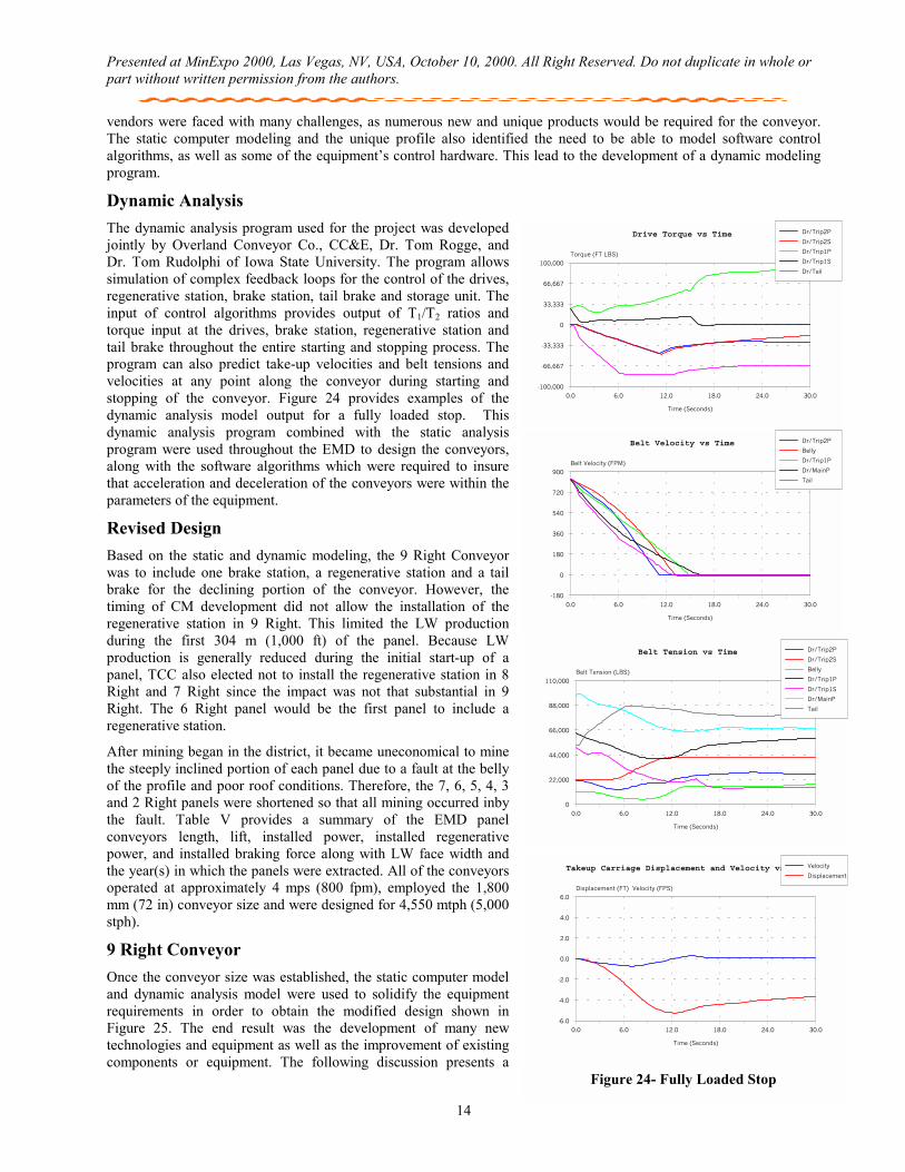
Once the scenarios were developed, the conceptual design of the conveyor was established using static computer modeling. The final design of the conveyor included a total of 3,880 kW (5,600 hp) of connected power and 278 kN-m (205,000 ft-lbs) of connected braking force. The final 9 Right panel design resulting from this modeling is shown in Figure 22. The full load running, stopping and acceleration results of the static modeling performed by CC&E for the design are shown in Figure 23. Based on the results of the static modeling, the
Figure 22
Presented at MinExpo 2000, Las Vegas, NV, USA, October 10, 2000. All Right Reserved. Do not duplicate in whole or part without written permission from the authors.
14
vendors were faced with many challenges, as numerous new and unique products would be required for the conveyor. The static computer modeling and the unique profile also identified the need to be able to model software control algorithms, as well as some of the equipment’s control hardware. This lead to the development of a dynamic modeling program.
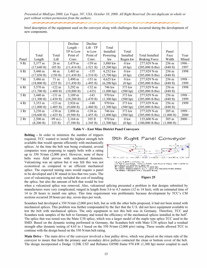
Dynamic Analysis The dynamic analysis program used for the project was developed jointly by Overland Conveyor Co., CC&E, Dr. Tom Rogge, and Dr. Tom Rudolphi of Iowa State University. The program allows simulation of complex feedback loops for the control of the drives, regenerative station, brake station, tail brake and storage unit. The input of control algorithms provides output of T1/T2 ratios and torque input at the drives, brake station, regenerative station and tail brake throughout the entire starting and stopping process. The program can also predict take-up velocities and belt tensions and velocities at any point along the conveyor during starting and stopping of the conveyor. Figure 24 provides examples of the dynamic analysis model output for a fully loaded stop. This dynamic analysis program combined with the static analysis program were used throughout the EMD to design the conveyors, along with the software algorithms which were required to insure that acceleration and deceleration of the conveyors were within the parameters of the equipment.
Revised Design
Based on the static and dynamic modeling, the 9 Right Conveyor was to include one brake station, a regenerative station and a tail brake for the declining portion of the conveyor. However, the timing of CM development did not allow the installation of the regenerative station in 9 Right. This limited the LW production during the first 304 m (1,000 ft) of the panel. Because LW production is generally reduced during the initial start-up of a panel, TCC also elected not to install the regenerative station in 8 Right and 7 Right since the impact was not that substantial in 9 Right. The 6 Right panel would be the first panel to include a regenerative station.
After mining began in the district, it became uneconomical to mine the steeply inclined portion of each panel due to a fault at the belly of the profile and poor roof conditions. Therefore, the 7, 6, 5, 4, 3 and 2 Right panels were shortened so that all mining occurred inby the fault. Table V provides a summary of the EMD panel conveyors length, lift, installed power, installed regenerative power, and installed braking force along with LW face width and the year(s) in which the panels were extracted. All of the conveyors operated at approximately 4 mps (800 fpm), employed the 1,800 mm (72 in) conveyor size and were designed for 4,550 mtph (5,000 stph).
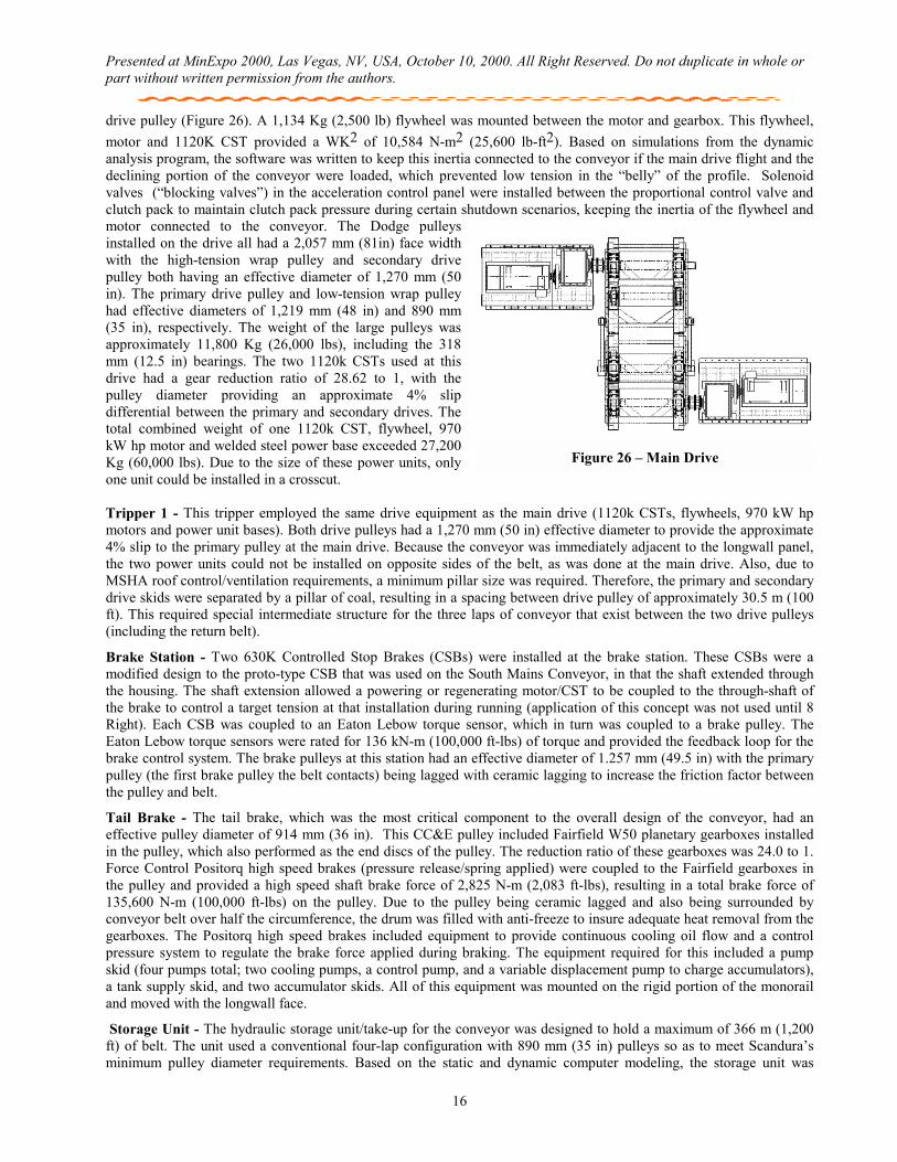
9 Right Conveyor
Once the conveyor size was established, the static computer model and dynamic analysis model were used to solidify the equipment requirements in order to obtain the modified design shown in Figure 25. The end result was the development of many new technologies and equipment as well as the improvement of existing components or equipment. The following discussion presents a
Belt Velocity vs Time
0.0 6.0 12.0 18.0 24.0 30.0
-180
0
180
360
540
720
900
Time (Seconds)
Belt Velocity (FPM)
Dr/Trip2P
Belly
Dr/Trip1P
Dr/MainP
Tail
Drive Torque vs Time
0.0 6.0 12.0 18.0 24.0 30.0
-100,000
-66,667
-33,333
0
33,333
66,667
100,000
Time (Seconds)
Torque (FT LBS)
Dr/Trip2P
Dr/Trip2S
Dr/Trip1P
Dr/Trip1S
Dr/Tail
Takeup Carriage Displacement and Velocity vs Time
0.0 6.0 12.0 18.0 24.0 30.0
-6.0
-4.0
-2.0
0.0
2.0
4.0
6.0
Time (Seconds)
Displacement (FT) Velocity (FPS)
Velocity
Displacement
Belt Tension vs Time
0.0 6.0 12.0 18.0 24.0 30.0
0
22,000
44,000
66,000
88,000
110,000
Time (Seconds)
Belt Tension (LBS)
Dr/Trip2P
Dr/Trip2S
Belly
Dr/Trip1P
Dr/Trip1S
Dr/MainP
Tail
Figure 24- Fully Loaded Stop
Presented at MinExpo 2000, Las Vegas, NV, USA, October 10, 2000. All Right Reserved. Do not duplicate in whole or part without written permission from the authors.
15
brief description of the equipment used on the conveyor along with challenges that occurred during the development of new components.
Panel
Total Length
Total Lift
Decline Length –
TP to Low Point of Conv.
Decline Lift - TP to Low Point of Conv.
Total
Installed Powering
kw
Total Installed
Regen kw
Total Installed Braking Force
Panel Face
Width
Year Mined
9 Rt 5,377 m (17,640 ft)
26 m (85 ft)
3,479 m (11,414 ft)
-159 m (-521 ft)
3,880 kw (5,200 hp)
0 kw (0 hp)
277,929 N-m (205,000 ft-lbs)
256 m (840 ft)
1996 –1997
8 Rt 5,440 m (17,850 ft)
46 m (150 ft)
3,483 m (11,430 ft)
-155 (-510 ft)
4,252 kw (5,700 hp)
0 kw (0 hp)
277,929 N-m (205,000 ft-lbs)
256 m (840 ft)
1998
7 Rt 5,486 m (18,000 ft)
71 m (235 ft)
3,490 m (11,450 ft)
-151 m (-495 ft)
4,625 kw (6,200 hp)
0 kw (0 hp)
277,929 N-m (205,000 ft-lbs)
256 m (840 ft)
1998 –1999
6 Rt 3,570 m (11,700 ft)
-122 m (-400 ft)
3,292 m (10,800 ft)
-132 m (-435)
746 kw (1,000 hp)
373 kw (500 hp)
277,929 N-m (205,000 ft-lbs)
256 m (840 ft)
1998
5 Rt 3,440 m (11,300 ft)
-131 m (-430 ft)
3,109 m (10,200 ft)
-143 (-470 ft)
970 kw (1,300 hp)
373 kw (500 hp)
277,929 N-m (205,000 ft-lbs)
256 m (840 ft)
1998 – 1999
4 Rt 3,353 m (11,000 ft)
-123 m (-405 ft)
2,926 m (9,600 ft)
-140 (-460 ft)
970 kw (1,300 hp)
373 kw (500 hp)
277,929 N-m (205,000 ft-lbs)
256 m (840 ft)
1999
3 Rt 3,230 m (10,600 ft)
-130 m (-425 ft)
2,896 m (9,500 ft)
-138 m (-455 ft)
746 kw (1,000 hp)
373 kw (500 hp)
277,929 N-m (205,000 ft-lbs)
205 m (1,000 ft)
1999 – 2000
2 Rt 2,500 m (8,200 ft)
-99 m (-325 ft)
2,164 m (7,100 ft)
105 ft (-345 ft)
970 kw (1,300 hp)
0 kw (0 hp)
135,600 N-m (100,000 ft-lbs)
305 m (1,000 ft)
2000 –
Table V - East Mine District Panel Conveyors
Belting - In order to minimize the number of trippers required, TCC wanted to install the highest strength belt available that would operate efficiently with mechanically splices. At the time the belt was being evaluated, several companies were proposing to supply belts with a rating up to 350 N/mm (2,000 piw). However, none of these belts were field proven with mechanical fasteners. Vulcanizing was an option but it was felt this was not economical as compared to an efficient mechanical splice. The expected mining rates would require a panel to be developed and LW mined in less that two years. The cost of vulcanizing not only included the cost of installing the splice, but also the amount of belt that would be lost when a vulcanized splice was removed. Also, vulcanized splicing presented a problem in that designs submitted by manufactures were very complicated, ranged in length from 3.6 to 4.3 meters (12 to 14 feet), with an estimated time of 14 to 20 hours to install one splice. This time requirement was problematic because development by TCC’s CM sections occurred 20 hours per day, seven days per week.
Scandura had developed a 350 N/mm (2,000 piw) belt, but as with the other belts proposed, it had not been tested with mechanical splices. This problem was further compounded by the fact that the U.S. did not have equipment available to test the belt with mechanical splices. The only equipment to test this belt was in Germany. Therefore, TCC and Scandura took samples of the belt to Germany and tested the efficiency of the mechanical splices installed in the belt8. The splice that was tested was the Mato U38 splice, which was a larger model of the staple type splice TCC used in the SMD. Based on the dynamic testing performed in Germany, the Scandura belt with Mato U38 splices had a residual strength after dynamic testing of 4.65 to 1 based on the 350 N/mm (2,000 piw) rating. These results allowed TCC to continue with the design based on the 350 N/mm belt rating.
Main Drive - The main drive of the conveyor involved a four pulley drive, which was placed on the return side of the conveyor to insure that both the primary and secondary drive pulleys contacted the clean or bottom cover of the belt. The design incorporated a Dodge 1120K CST and Reliance G9500 frame 970 kW (1,300 hp) motor coupled to each
Figure 25
Presented at MinExpo 2000, Las Vegas, NV, USA, October 10, 2000. All Right Reserved. Do not duplicate in whole or part without written permission from the authors.
16
drive pulley (Figure 26). A 1,134 Kg (2,500 lb) flywheel was mounted between the motor and gearbox. This flywheel, motor and 1120K CST provided a WK2 of 10,584 N-m2 (25,600 lb-ft2). Based on simulations from the dynamic analysis program, the software was written to keep this inertia connected to the conveyor if the main drive flight and the declining portion of the conveyor were loaded, which prevented low tension in the “belly” of the profile. Solenoid valves (“blocking valves”) in the acceleration control panel were installed between the proportional control valve and clutch pack to maintain clutch pack pressure during certain shutdown scenarios, keeping the inertia of the flywheel and motor connected to the conveyor. The Dodge pulleys installed on the drive all had a 2,057 mm (81in) face width with the high-tension wrap pulley and secondary drive pulley both having an effective diameter of 1,270 mm (50 in). The primary drive pulley and low-tension wrap pulley had effective diameters of 1,219 mm (48 in) and 890 mm (35 in), respectively. The weight of the large pulleys was approximately 11,800 Kg (26,000 lbs), including the 318 mm (12.5 in) bearings. The two 1120k CSTs used at this drive had a gear reduction ratio of 28.62 to 1, with the pulley diameter providing an approximate 4% slip differential between the primary and secondary drives. The total combined weight of one 1120k CST, flywheel, 970 kW hp motor and welded steel power base exceeded 27,200 Kg (60,000 lbs). Due to the size of these power units, only one unit could be installed in a crosscut. Tripper 1 - This tripper employed the same drive equipment as the main drive (1120k CSTs, flywheels, 970 kW hp motors and power unit bases). Both drive pulleys had a 1,270 mm (50 in) effective diameter to provide the approximate 4% slip to the primary pulley at the main drive. Because the conveyor was immediately adjacent to the longwall panel, the two power units could not be installed on opposite sides of the belt, as was done at the main drive. Also, due to MSHA roof control/ventilation requirements, a minimum pillar size was required. Therefore, the primary and secondary drive skids were separated by a pillar of coal, resulting in a spacing between drive pulley of approximately 30.5 m (100 ft). This required special intermediate structure for the three laps of conveyor that exist between the two drive pulleys (including the return belt).
Brake Station - Two 630K Controlled Stop Brakes (CSBs) were installed at the brake station. These CSBs were a modified design to the proto-type CSB that was used on the South Mains Conveyor, in that the shaft extended through the housing. The shaft extension allowed a powering or regenerating motor/CST to be coupled to the through-shaft of the brake to control a target tension at that installation during running (application of this concept was not used until 8 Right). Each CSB was coupled to an Eaton Lebow torque sensor, which in turn was coupled to a brake pulley. The Eaton Lebow torque sensors were rated for 136 kN-m (100,000 ft-lbs) of torque and provided the feedback loop for the brake control system. The brake pulleys at this station had an effective diameter of 1.257 mm (49.5 in) with the primary pulley (the first brake pulley the belt contacts) being lagged with ceramic lagging to increase the friction factor between the pulley and belt.
Tail Brake - The tail brake, which was the most critical component to the overall design of the conveyor, had an effective pulley diameter of 914 mm (36 in). This CC&E pulley included Fairfield W50 planetary gearboxes installed in the pulley, which also performed as the end discs of the pulley. The reduction ratio of these gearboxes was 24.0 to 1. Force Control Positorq high speed brakes (pressure release/spring applied) were coupled to the Fairfield gearboxes in the pulley and provided a high speed shaft brake force of 2,825 N-m (2,083 ft-lbs), resulting in a total brake force of 135,600 N-m (100,000 ft-lbs) on the pulley. Due to the pulley being ceramic lagged and also being surrounded by conveyor belt over half the circumference, the drum was filled with anti-freeze to insure adequate heat removal from the gearboxes. The Positorq high speed brakes included equipment to provide continuous cooling oil flow and a control pressure system to regulate the brake force applied during braking. The equipment required for this included a pump skid (four pumps total; two cooling pumps, a control pump, and a variable displacement pump to charge accumulators), a tank supply skid, and two accumulator skids. All of this equipment was mounted on the rigid portion of the monorail and moved with the longwall face. Storage Unit - The hydraulic storage unit/take-up for the conveyor was designed to hold a maximum of 366 m (1,200 ft) of belt. The unit used a conventional four-lap configuration with 890 mm (35 in) pulleys so as to meet Scandura’s minimum pulley diameter requirements. Based on the static and dynamic computer modeling, the storage unit was
Figure 26 – Main Drive
Presented at MinExpo 2000, Las Vegas, NV, USA, October 10, 2000. All Right Reserved. Do not duplicate in whole or part without written permission from the authors.
17
designed to provide a maximum belt tension of 245 kN (55,000 lbs). In order to obtain this force, CC&E installed a sheave carriage (which was attached to the mobile carriage) to allow the winch rope force to be doubled on the mobile carriage. Using the dynamic analysis model, the unit was designed to provide a mobile carriage speed of 0.3 mps (1 fps). As part of the design of the system, CC&E incorporated load cells in the storage units to determine the belt tension. This tension was used in a feedback loop to the Allen/Bradley Control System to control the variable displacement pump and maintain a constant tension in the storage unit.
Belt Winder – In order to minimize the frequency which belt was installed (CM development) or removed (LW retreat) from the conveyor, the belt was purchased in 244m (800 ft) rolls. It was apparent that due to the size of each roll of the 1,800 mm belt, which weighed 12,700 Kg (28,000 lbs) and had a diameter of 2.87 m (113 in), an efficient handling system would be required to prevent mining delays. In order to handle this size of roll, TCC and CC&E designed a system that allowed the belt to be wound in the vertical position (on the edge of the belt). The belt winding system included a pinch roll design to pull belt from the storage unit and 45 degree and 90 degree hydraulic operated rotation devices to position the belt vertically for winding. This unit included hydraulic motors and gear drives for winding and included its own tramming system. Due to the steep cross grade, it was necessary to tram the roll of belt out of the conveyor entry to allow a Wagner 25X Scoop to access the roll. The unit was also designed to allow individual tables/spools to be installed in the winder for each roll of belt.
Due to the weight of the belt, installing and replacing mechanical splices would require mechanical equipment. The belt winder system was designed with two self-propelled splicing tables that allowed the two ends of the belt to be brought together for pin insertion. Also, since the Mato U-38 splices required that both sides of the belt be skived, a dual comb bar was installed on the tables. This allowed both the bottom and top covers to be skived and Mato clips to be installed without repositioning the belt.
The entire belt handling system obtained the required hydraulic power from auxiliary pumps installed at the storage unit’s winch power pack unit.
Conveyor Intermediate Structure - When 1,800 mm structure was selected for the EMD panel conveyors, it was understood that the past structure handling practices used for the 1,400 mm (54 in) structure in the WMD and SMD districts would not be acceptable. The weight of 1,800 mm top idlers was approximately 127 Kg (280 lbs) and the weight of a return idler was 118Kg (260 lbs). In order to safely and efficiently handle this large structure, TCC and CC&E developed unique designs for the idlers. The top idlers were designed with removable side brackets, which allowed removal of the side brackets and the wing rolls. Further, CC&E provided a design that replaced the normal roller shell with an 8-gauge shell and driscol pipe sleeve, which reduced the roll weight by 7 Kg (16 lbs). Upon removing the side brackets and wing rolls, the weight of the frame and center roll was reduced to less than 63 Kg (140 lbs). The removable side bracket design not only allowed the weight of the idler to be reduced by disassembly, it also provided a more compact package for transport into the mine.
The return idlers also used the 8-gauge shell and driscol sleeve, reducing the roll weight by approximately 11 Kg (25 lbs) per roll. TCC and CC&E developed a V-return frame design that was hinged on one end and employed the conventional underground “J” bolt fastening system. This return frame design allowed the rolls to be removed and thus reduce the overall weight to less that 54 Kg (120 lbs). The hinged arrangement and “J” bolt fastening system significantly reduced the installation and removal time requirements.
Scissorveyor – While the heavy 1,800 mm structure was addressed from a safety standpoint by designing the structure to be disassembled, the potential for LW production delays still existed. The concern was that the larger structure and belt, combined with the high tail tensions that existed when the LW was on the declining portion of the profile, would cause considerable delays if the structure was removed during a production shift. Therefore, TCC and CC&E developed a conveyor structure system (“scissorveyor”) that allowed the system to be retracted automatically during production without causing production delays. During the idle period or shift, the roof hung structure could then be removed and the scissorveyor extended prior to the next LW production shift. The design of this system originally began in the 3 Southwest panel and was completed in the 9 Right panel.
Software – CC&E introduced TCC to PID control loops for the 9 Right panel conveyor. The main advantage of this type of software was that it provided easier trouble shooting than TCC’s previously written control software. During the 9 Right panel, TCC developed a “bit parade” software that tracked the loading on the conveyor. This software, combined with the static and dynamic programs, was used in 8 Right and all other panels in the EMD to set the initial target torque of the tail brake and CSB brakes during stopping.
Presented at MinExpo 2000, Las Vegas, NV, USA, October 10, 2000. All Right Reserved. Do not duplicate in whole or part without written permission from the authors.
18
9 Right Panel Conveyor Problems While the system was successful, there were some problems that occurred. These problems are discussed below.
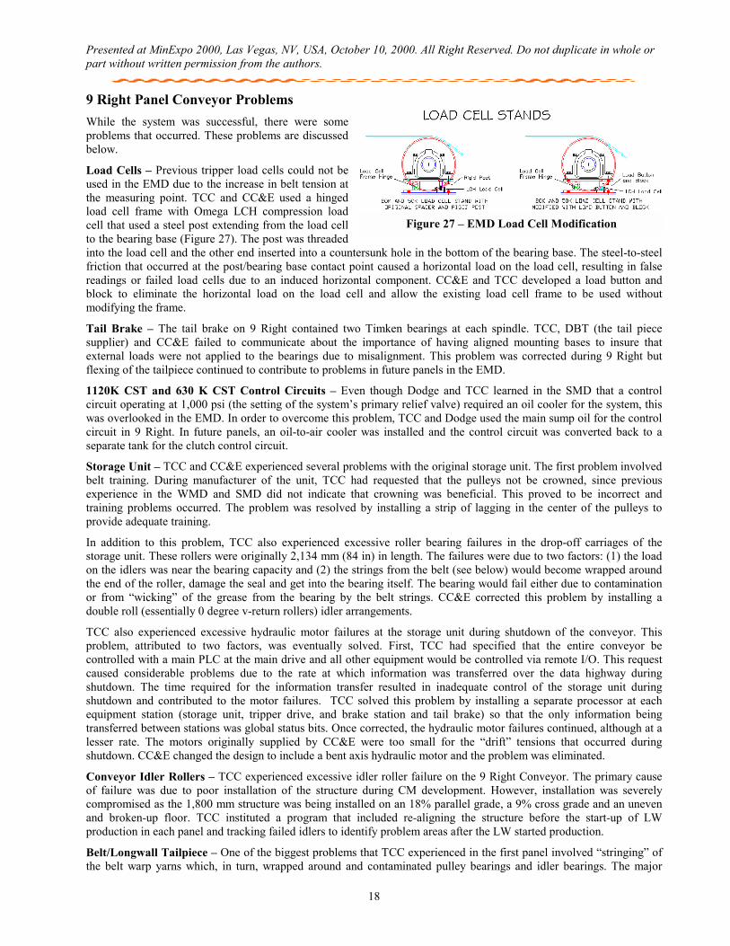
Load Cells – Previous tripper load cells could not be used in the EMD due to the increase in belt tension at the measuring point. TCC and CC&E used a hinged load cell frame with Omega LCH compression load cell that used a steel post extending from the load cell to the bearing base (Figure 27). The post was threaded into the load cell and the other end inserted into a countersunk hole in the bottom of the bearing base. The steel-to-steel friction that occurred at the post/bearing base contact point caused a horizontal load on the load cell, resulting in false readings or failed load cells due to an induced horizontal component. CC&E and TCC developed a load button and block to eliminate the horizontal load on the load cell and allow the existing load cell frame to be used without modifying the frame.
Tail Brake – The tail brake on 9 Right contained two Timken bearings at each spindle. TCC, DBT (the tail piece supplier) and CC&E failed to communicate about the importance of having aligned mounting bases to insure that external loads were not applied to the bearings due to misalignment. This problem was corrected during 9 Right but flexing of the tailpiece continued to contribute to problems in future panels in the EMD.
1120K CST and 630 K CST Control Circuits – Even though Dodge and TCC learned in the SMD that a control circuit operating at 1,000 psi (the setting of the system’s primary relief valve) required an oil cooler for the system, this was overlooked in the EMD. In order to overcome this problem, TCC and Dodge used the main sump oil for the control circuit in 9 Right. In future panels, an oil-to-air cooler was installed and the control circuit was converted back to a separate tank for the clutch control circuit.
Storage Unit – TCC and CC&E experienced several problems with the original storage unit. The first problem involved belt training. During manufacturer of the unit, TCC had requested that the pulleys not be crowned, since previous experience in the WMD and SMD did not indicate that crowning was beneficial. This proved to be incorrect and training problems occurred. The problem was resolved by installing a strip of lagging in the center of the pulleys to provide adequate training.
In addition to this problem, TCC also experienced excessive roller bearing failures in the drop-off carriages of the storage unit. These rollers were originally 2,134 mm (84 in) in length. The failures were due to two factors: (1) the load on the idlers was near the bearing capacity and (2) the strings from the belt (see below) would become wrapped around the end of the roller, damage the seal and get into the bearing itself. The bearing would fail either due to contamination or from “wicking” of the grease from the bearing by the belt strings. CC&E corrected this problem by installing a double roll (essentially 0 degree v-return rollers) idler arrangements.
TCC also experienced excessive hydraulic motor failures at the storage unit during shutdown of the conveyor. This problem, attributed to two factors, was eventually solved. First, TCC had specified that the entire conveyor be controlled with a main PLC at the main drive and all other equipment would be controlled via remote I/O. This request caused considerable problems due to the rate at which information was transferred over the data highway during shutdown. The time required for the information transfer resulted in inadequate control of the storage unit during shutdown and contributed to the motor failures. TCC solved this problem by installing a separate processor at each equipment station (storage unit, tripper drive, and brake station and tail brake) so that the only information being transferred between stations was global status bits. Once corrected, the hydraulic motor failures continued, although at a lesser rate. The motors originally supplied by CC&E were too small for the “drift” tensions that occurred during shutdown. CC&E changed the design to include a bent axis hydraulic motor and the problem was eliminated.
Conveyor Idler Rollers – TCC experienced excessive idler roller failure on the 9 Right Conveyor. The primary cause of failure was due to poor installation of the structure during CM development. However, installation was severely compromised as the 1,800 mm structure was being installed on an 18% parallel grade, a 9% cross grade and an uneven and broken-up floor. TCC instituted a program that included re-aligning the structure before the start-up of LW production in each panel and tracking failed idlers to identify problem areas after the LW started production.
Belt/Longwall Tailpiece – One of the biggest problems that TCC experienced in the first panel involved “stringing” of the belt warp yarns which, in turn, wrapped around and contaminated pulley bearings and idler bearings. The major
Figure 27 – EMD Load Cell Modification
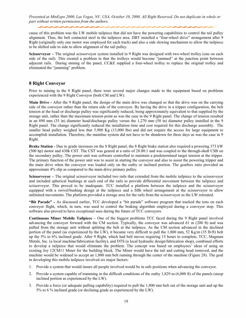
Presented at MinExpo 2000, Las Vegas, NV, USA, October 10, 2000. All Right Reserved. Do not duplicate in whole or part without written permission from the authors.
19
cause of this problem was the LW mobile tailpiece that did not have the powering capabilities to control the tail pulley alignment. Thus, the belt contacted steel in the tailpiece area. DBT installed a “four-wheel drive” arrangement after 9 Right (originally only one motor was employed for each track) and also a side slewing mechanism to allow the tailpiece to be shifted side to side to allow alignment of the tail pulley.
Scissorveyor – The original scissorveyor system installed in 9 Right was designed with two-wheel trolley (one on each side of the rail). This created a problem in that the trolleys would become “jammed” at the junction point between adjacent rails. During mining of the panel, CC&E supplied a four-wheel trolley to replace the original trolley and eliminated the “jamming” problem.
8 Right Conveyor Prior to mining in the 8 Right panel, there were several major changes made to the equipment based on problems experienced with the 9 Right Conveyor (both CM and LW).
Main Drive - After the 9 Right panel, the design of the main drive was changed so that the drive was on the carrying side of the conveyor rather than the return side of the conveyor. By having the drive in a tripper configuration, the belt tension at the head or discharge pulley was significantly reduced, being approximately equivalent to that supplied by the storage unit, rather than the maximum tension point as was the case in the 9 Right panel. The change of tension resulted in an 890 mm (35 in) diameter head/discharge pulley versus the 1,270 mm (50 in) diameter pulley installed in the 9 Right panel. The change significantly reduced the installation time and cost required for this discharge assembly. The smaller head pulley weighed less that 5,900 Kg (13,000 lbs) and did not require the access for large equipment to accomplish installation. Therefore, the mainline system did not have to be shutdown for three days as was the case in 9 Right.
Brake Station - Due to grade increases on the 8 Right panel, the 8 Right brake station also required a powering 373 kW (500 hp) motor and 630k CST. The CST was geared at a ratio of 28.00:1 and was coupled to the through-shaft CSB on the secondary pulley. The power unit was software controlled to maintain a predetermined target tension at the tripper. The primary function of the power unit was to assist in starting the conveyor and also to assist the powering tripper and the main drive when the conveyor was loaded only on the outby or inclined portion. The gearbox ratio provided an approximate 4% slip as compared to the main drive primary pulley.
Scissorveyor – The original scissorveyor included two rails that extended from the mobile tailpiece to the scissorveyor and included spherical bushings at each end of the rails to provide differential movement between the tailpiece and scissorveyor. This proved to be inadequate. TCC installed a platform between the tailpiece and the scissorveyor equipped with a swivel/bushing design at the tailpiece and a fifth wheel arrangement at the scissorveyor to allow unlimited movements. The platform provided a storage area for the rails from the scissorveyor as the LW retreated.
“Bit Parade” - As discussed earlier, TCC developed a “bit parade” software program that tracked the tons on each conveyor flight, which, in turn, was used to control the braking algorithm employed during a conveyor stop. This software also proved to have exceptional uses during the future of TCC conveyors.
Continuous Miner Mobile Tailpiece – One of the biggest problems TCC faced during the 9 Right panel involved advancing the conveyor forward with the CM section. Typically, the conveyor was advanced 61 m (200 ft) and was pulled from the storage unit without splitting the belt at the tailpiece. As the CM section advanced in the declined portion of the panel (as experienced by the LW), it became very difficult to pull the 1,800 mm, 52 Kg/m (35 lb/ft) belt up the 5% to 6% inclined grade. After 9 Right, which had belt moves requiring 15 hours to complete, TCC, Magnum Metals, Inc. (a local machine/fabrication facility), and DTS (a local hydraulic design/fabrication shop), combined efforts to develop a tailpiece that would eliminate the problem. The concept was based on employees’ ideas of using an existing Joy 12CM11 Miner for the building block. The Miner would have the tail and cutting head removed, and the machine would be widened to accept an 1,800 mm belt running through the center of the machine (Figure 28). The goal in developing this mobile tailpiece involved six major factors:
1. Provide a system that would insure all people involved would be in safe positions when advancing the conveyor.
2. Provide a system capable of tramming in the difficult conditions of the outby 1,829 m (6,000 ft) of the panels (steep inclined portion as experienced by the LW).
3. Provide a force (or adequate pulling capability) required to pull the 1,800 mm belt out of the storage unit and up the 5% to 6 % inclined grade (or declining grade as experienced by the LW).
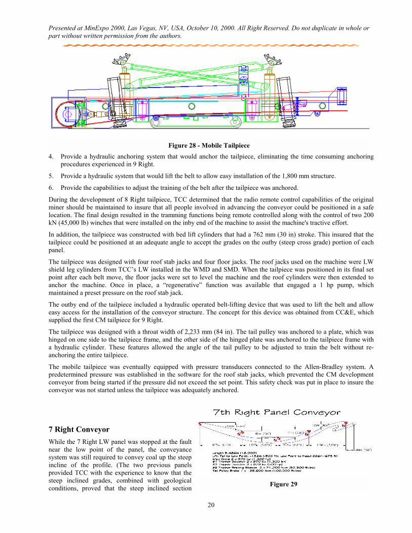
Presented at MinExpo 2000, Las Vegas, NV, USA, October 10, 2000. All Right Reserved. Do not duplicate in whole or part without written permission from the authors.
20
4. Provide a hydraulic anchoring system that would anchor the tailpiece, eliminating the time consuming anchoring procedures experienced in 9 Right.
5. Provide a hydraulic system that would lift the belt to allow easy installation of the 1,800 mm structure.
6. Provide the capabilities to adjust the training of the belt after the tailpiece was anchored.
During the development of 8 Right tailpiece, TCC determined that the radio remote control capabilities of the original miner should be maintained to insure that all people involved in advancing the conveyor could be positioned in a safe location. The final design resulted in the tramming functions being remote controlled along with the control of two 200 kN (45,000 lb) winches that were installed on the inby end of the machine to assist the machine's tractive effort.
In addition, the tailpiece was constructed with bed lift cylinders that had a 762 mm (30 in) stroke. This insured that the tailpiece could be positioned at an adequate angle to accept the grades on the outby (steep cross grade) portion of each panel.
The tailpiece was designed with four roof stab jacks and four floor jacks. The roof jacks used on the machine were LW shield leg cylinders from TCC’s LW installed in the WMD and SMD. When the tailpiece was positioned in its final set point after each belt move, the floor jacks were set to level the machine and the roof cylinders were then extended to anchor the machine. Once in place, a “regenerative” function was available that engaged a 1 hp pump, which maintained a preset pressure on the roof stab jack.
The outby end of the tailpiece included a hydraulic operated belt-lifting device that was used to lift the belt and allow easy access for the installation of the conveyor structure. The concept for this device was obtained from CC&E, which supplied the first CM tailpiece for 9 Right.
The tailpiece was designed with a throat width of 2,233 mm (84 in). The tail pulley was anchored to a plate, which was hinged on one side to the tailpiece frame, and the other side of the hinged plate was anchored to the tailpiece frame with a hydraulic cylinder. These features allowed the angle of the tail pulley to be adjusted to train the belt without re-anchoring the entire tailpiece.
The mobile tailpiece was eventually equipped with pressure transducers connected to the Allen-Bradley system. A predetermined pressure was established in the software for the roof stab jacks, which prevented the CM development conveyor from being started if the pressure did not exceed the set point. This safety check was put in place to insure the conveyor was not started unless the tailpiece was adequately anchored.
7 Right Conveyor While the 7 Right LW panel was stopped at the fault near the low point of the panel, the conveyance system was still required to convey coal up the steep incline of the profile. (The two previous panels provided TCC with the experience to know that the steep inclined grades, combined with geological conditions, proved that the steep inclined section Figure 29
Figure 28 - Mobile Tailpiece
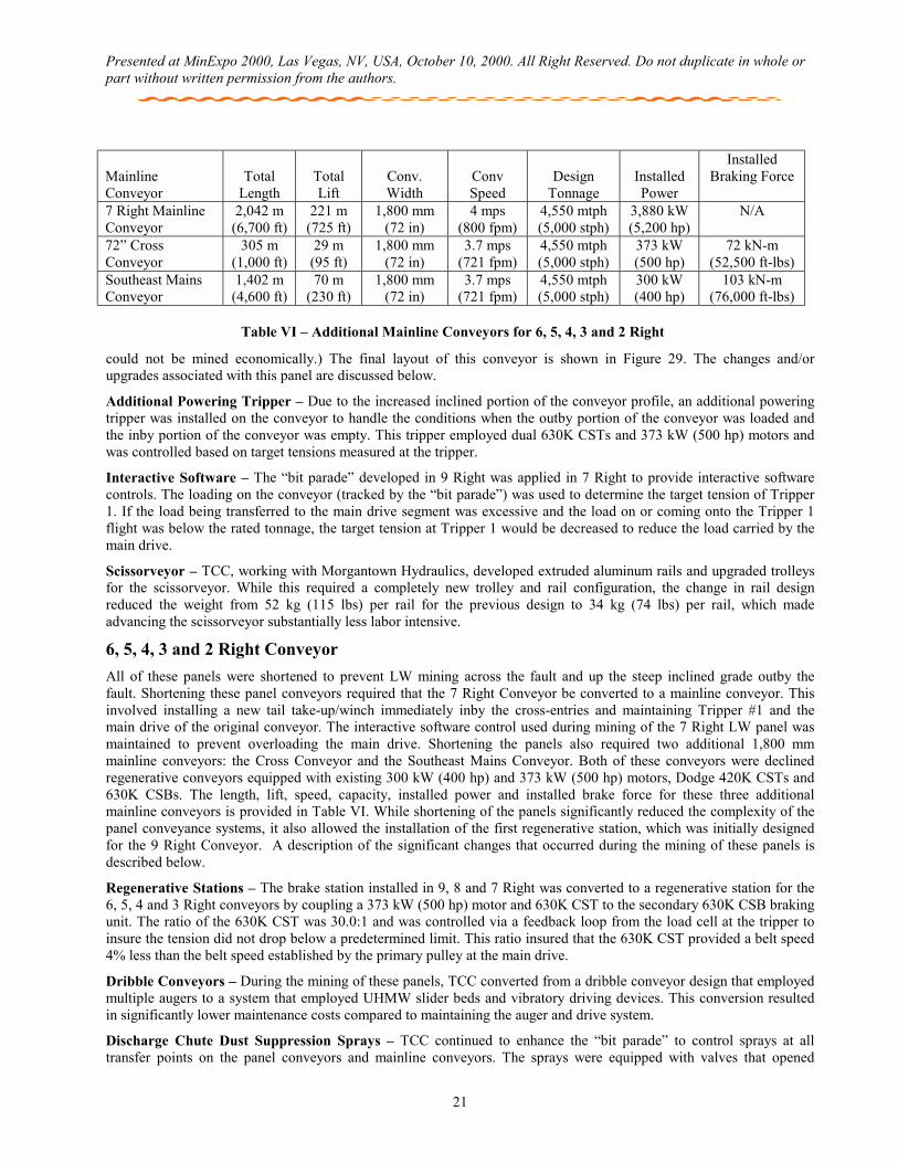
Presented at MinExpo 2000, Las Vegas, NV, USA, October 10, 2000. All Right Reserved. Do not duplicate in whole or part without written permission from the authors.
21
could not be mined economically.) The final layout of this conveyor is shown in Figure 29. The changes and/or upgrades associated with this panel are discussed below.
Additional Powering Tripper – Due to the increased inclined portion of the conveyor profile, an additional powering tripper was installed on the conveyor to handle the conditions when the outby portion of the conveyor was loaded and the inby portion of the conveyor was empty. This tripper employed dual 630K CSTs and 373 kW (500 hp) motors and was controlled based on target tensions measured at the tripper.
Interactive Software – The “bit parade” developed in 9 Right was applied in 7 Right to provide interactive software controls. The loading on the conveyor (tracked by the “bit parade”) was used to determine the target tension of Tripper 1. If the load being transferred to the main drive segment was excessive and the load on or coming onto the Tripper 1 flight was below the rated tonnage, the target tension at Tripper 1 would be decreased to reduce the load carried by the main drive.
Scissorveyor – TCC, working with Morgantown Hydraulics, developed extruded aluminum rails and upgraded trolleys for the scissorveyor. While this required a completely new trolley and rail configuration, the change in rail design reduced the weight from 52 kg (115 lbs) per rail for the previous design to 34 kg (74 lbs) per rail, which made advancing the scissorveyor substantially less labor intensive.
6, 5, 4, 3 and 2 Right Conveyor All of these panels were shortened to prevent LW mining across the fault and up the steep inclined grade outby the fault. Shortening these panel conveyors required that the 7 Right Conveyor be converted to a mainline conveyor. This involved installing a new tail take-up/winch immediately inby the cross-entries and maintaining Tripper #1 and the main drive of the original conveyor. The interactive software control used during mining of the 7 Right LW panel was maintained to prevent overloading the main drive. Shortening the panels also required two additional 1,800 mm mainline conveyors: the Cross Conveyor and the Southeast Mains Conveyor. Both of these conveyors were declined regenerative conveyors equipped with existing 300 kW (400 hp) and 373 kW (500 hp) motors, Dodge 420K CSTs and 630K CSBs. The length, lift, speed, capacity, installed power and installed brake force for these three additional mainline conveyors is provided in Table VI. While shortening of the panels significantly reduced the complexity of the panel conveyance systems, it also allowed the installation of the first regenerative station, which was initially designed for the 9 Right Conveyor. A description of the significant changes that occurred during the mining of these panels is described below.
Regenerative Stations – The brake station installed in 9, 8 and 7 Right was converted to a regenerative station for the 6, 5, 4 and 3 Right conveyors by coupling a 373 kW (500 hp) motor and 630K CST to the secondary 630K CSB braking unit. The ratio of the 630K CST was 30.0:1 and was controlled via a feedback loop from the load cell at the tripper to insure the tension did not drop below a predetermined limit. This ratio insured that the 630K CST provided a belt speed 4% less than the belt speed established by the primary pulley at the main drive.
Dribble Conveyors – During the mining of these panels, TCC converted from a dribble conveyor design that employed multiple augers to a system that employed UHMW slider beds and vibratory driving devices. This conversion resulted in significantly lower maintenance costs compared to maintaining the auger and drive system.
Discharge Chute Dust Suppression Sprays – TCC continued to enhance the “bit parade” to control sprays at all transfer points on the panel conveyors and mainline conveyors. The sprays were equipped with valves that opened
Mainline Conveyor
Total
Length
Total Lift
Conv. Width
Conv Speed
Design
Tonnage
Installed Power
Installed Braking Force
7 Right Mainline Conveyor
2,042 m (6,700 ft)
221 m (725 ft)
1,800 mm (72 in)
4 mps (800 fpm)
4,550 mtph (5,000 stph)
3,880 kW (5,200 hp)
N/A
72” Cross Conveyor
305 m (1,000 ft)
29 m (95 ft)
1,800 mm (72 in)
3.7 mps (721 fpm)
4,550 mtph (5,000 stph)
373 kW (500 hp)
72 kN-m (52,500 ft-lbs)
Southeast Mains Conveyor
1,402 m (4,600 ft)
70 m (230 ft)
1,800 mm (72 in)
3.7 mps (721 fpm)
4,550 mtph (5,000 stph)
300 kW (400 hp)
103 kN-m (76,000 ft-lbs)
Table VI – Additional Mainline Conveyors for 6, 5, 4, 3 and 2 Right
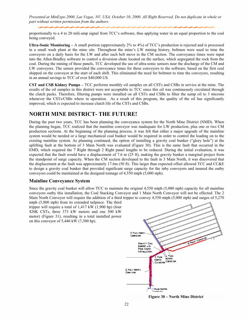
Presented at MinExpo 2000, Las Vegas, NV, USA, October 10, 2000. All Right Reserved. Do not duplicate in whole or part without written permission from the authors.
22
proportionally to a 4 to 20 mili-amp signal from TCC’s software, thus applying water in an equal proportion to the coal being conveyed.
Ultra-Sonic Monitoring – A small portion (approximately 2% to 4%) of TCC’s production is rejected and is processed in a small wash plant at the mine site. Throughout the mine’s LW mining history, beltmen were used to time the conveyors on a daily basis for the LW and after each belt move in the CM section. The conveyance times were input into the Allen-Bradley software to control a diversion chute located on the surface, which segregated the rock from the coal. During the mining of these panels, TCC developed the use of ultra-sonic sensors near the discharge of the CM and LW conveyors. The sensor provided the conveyance times for these conveyors to the software, based on the first coal shipped on the conveyor at the start of each shift. This eliminated the need for beltmen to time the conveyors, resulting in an annual savings to TCC of over $40,000 US.
CST and CSB Kidney Pumps – TCC performs monthly oil samples on all CSTs and CSBs in service at the mine. The results of the oil samples in this district were not acceptable to TCC since this oil was continuously circulated through the clutch packs. Therefore, filtering pumps were installed on all CSTs and CSBs to filter the sump oil to 3 microns whenever the CSTs/CSBs where in operation. As a result of this program, the quality of the oil has significantly improved, which is expected to increase clutch life of the CSTs and CSBs.
NORTH MINE DISTRICT- THE FUTURE! During the past two years, TCC has been planning the conveyance system for the North Mine District (NMD). When the planning began, TCC realized that the mainline conveyor was inadequate for LW production, plus one or two CM production sections. At the beginning of the planning process, it was felt that either a major upgrade of the mainline system would be needed or a large mechanical coal bunker would be required in order to control the loading on to the existing mainline system. As planning continued, the option of installing a gravity coal bunker (“glory hole”) at the uplifting fault at the bottom of 3 Main North was evaluated (Figure 30). This is the same fault that occurred in the EMD, which required the 7 Right through 2 Right panel lengths to be reduced. During the initial evaluation, it was expected that the fault would have a displacement of 7.6 m (25 ft), making the gravity bunker a marginal project from the standpoint of surge capacity. When the CM section developed to the fault in 3 Main North, it was discovered that the displacement at the fault was approximately 17.6m (50 ft). This larger than expected offset allowed TCC and CC&E to design a gravity coal bunker that provided significant surge capacity for the inby conveyors and insured the outby conveyors could be maintained at the designed tonnage of 4,550 mtph (5,000 stph).
Mainline Conveyance System Since the gravity coal bunker will allow TCC to maintain the original 4,550 mtph (5,000 stph) capacity for all mainline conveyors outby this installation, the Coal Stacking Conveyor and 1 Main North Conveyor will not be effected. The 2 Main North Conveyor will require the addition of a third tripper to convey 4,550 mtph (5,000 stph) and surges of 5,270 mtph (5,800 stph) from its extended tailpiece. The third tripper will require a total of 1,417 kW (1,900 hp) (four 420K CSTs, three 373 kW motors and one 300 kW motor) (Figure 31), resulting in a total installed power on this conveyor of 5,446 kW (7,300 hp).
Figure 30 – North Mine District
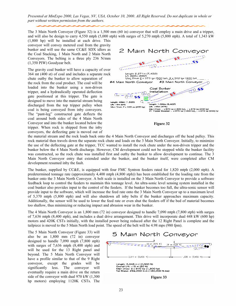
Presented at MinExpo 2000, Las Vegas, NV, USA, October 10, 2000. All Right Reserved. Do not duplicate in whole or part without written permission from the authors.
23
The 3 Main North Conveyor (Figure 32) is a 1,500 mm (60 in) conveyor that will employ a main drive and a tripper, and will also be design to carry 4,550 mtph (5,000 stph) with surges of 5,270 mtph (5,800 stph). A total of 1,343 kW (1,800 hp) will be installed at each drive. This conveyor will convey metered coal from the gravity bunker and will use the same CC&E SDX idlers as the Coal Stacking, 1 Main North and 2 Main North Conveyors. The belting is a three ply 236 N/mm (1,350 PIW) Goodyear belt.
The gravity coal bunker will have a capacity of over 364 mt (400 st) of coal and includes a separate rock chute outby the bunker to allow separation of the rock from the coal product. The coal will be loaded into the bunker using a non-driven tripper, and a hydraulically operated deflection gate positioned at this tripper. The gate is designed to move into the material stream being discharged from the top tripper pulley when coal is being conveyed from inby conveyors. The “pant-leg” constructed gate deflects the coal around both sides of the 4 Main North Conveyor and into the bunker located below the tripper. When rock is shipped from the inby conveyors, the deflecting gate is moved out of the material stream and the rock loads back onto the 4 Main North Conveyor and discharges off the head pulley. This rock material then travels down the separate rock chute and loads on the 3 Main North Conveyor. Initially, to minimize the use of the deflecting gate at the tripper, TCC wanted to install the rock chute under the non-driven tripper and the bunker below the 4 Main North discharge. However, CM development could not be stopped while the bunker facility was constructed, so the rock chute was installed first and outby the bunker to allow development to continue. The 3 Main North Conveyor entry that extended under the bunker, and the bunker itself, were completed after CM development resumed inby the fault.
The bunker, supplied by CC&E, is equipped with four FMC Syntron feeders rated for 1,820 mtph (2,000 stph). A predetermined tonnage rate (approximately 4,400 mtph (4,800 stph)) has been established for the loading rate from the bunker onto the 3 Main North Conveyor. A belt scale is installed on the 3 Main North Conveyor to provide a software feedback loop to control the feeders to maintain this tonnage level. An ultra-sonic level sensing system installed in the coal bunker also provides input to the control of the feeders. If the bunker becomes too full, the ultra-sonic sensor will provide input to the software, which will increase the feed rate onto the 3 Main North Conveyor up to a maximum level of 5,370 mtph (5,800 stph) and will also shutdown all inby belts if the bunker approaches maximum capacity. Additionally, the sensor will be used to lower the feed rate or even shut the feeders off if the bed of material becomes too shallow, thus minimizing or reducing impact and abrasion wear in the bunker.
The 4 Main North Conveyor is an 1,800 mm (72 in) conveyor designed to handle 7,090 mtph (7,800 stph) with surges of 7,636 mtph (8,400 stph), and includes a dual drive arrangement. This drive will incorporate dual 448 kW (600 hp) motors and 420K CSTs initially, with the installed power being reduced after the 12 Right Panel is complete and the tailpiece is moved to the 5 Main North load point. The speed of the belt will be 4.98 mps (980 fpm).
The 5 Main North Conveyor (Figure 33) will also be an 1,800 mm (72 in) conveyor designed to handle 7,090 mtph (7,800 stph) with surges of 7,636 mtph (8,400 stph) and will be used for the 13 Right panel and beyond. The 5 Main North Conveyor will have a profile similar to that of the 9 Right conveyor, except the grades will be significantly less. The conveyor will eventually require a main drive on the return side of the conveyor with dual 970 kW (1,300 hp motors) employing 1120K CSTs. The
Figure 31
Figure 33
Figure 32
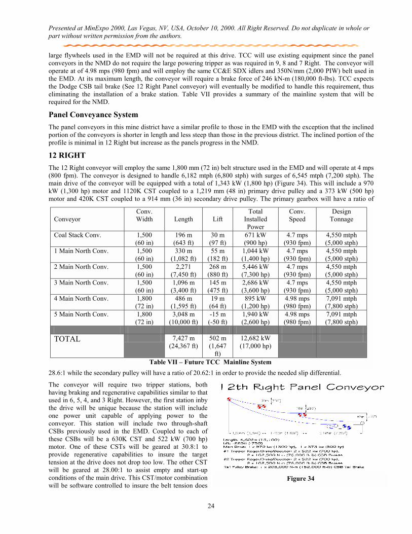
Presented at MinExpo 2000, Las Vegas, NV, USA, October 10, 2000. All Right Reserved. Do not duplicate in whole or part without written permission from the authors.
24
large flywheels used in the EMD will not be required at this drive. TCC will use existing equipment since the panel conveyors in the NMD do not require the large powering tripper as was required in 9, 8 and 7 Right. The conveyor will operate at of 4.98 mps (980 fpm) and will employ the same CC&E SDX idlers and 350N/mm (2,000 PIW) belt used in the EMD. At its maximum length, the conveyor will require a brake force of 246 kN-m (180,000 ft-lbs). TCC expects the Dodge CSB tail brake (See 12 Right Panel conveyor) will eventually be modified to handle this requirement, thus eliminating the installation of a brake station. Table VII provides a summary of the mainline system that will be required for the NMD.
Panel Conveyance System The panel conveyors in this mine district have a similar profile to those in the EMD with the exception that the inclined portion of the conveyors is shorter in length and less steep than those in the previous district. The inclined portion of the profile is minimal in 12 Right but increase as the panels progress in the NMD.
12 RIGHT The 12 Right conveyor will employ the same 1,800 mm (72 in) belt structure used in the EMD and will operate at 4 mps (800 fpm). The conveyor is designed to handle 6,182 mtph (6,800 stph) with surges of 6,545 mtph (7,200 stph). The main drive of the conveyor will be equipped with a total of 1,343 kW (1,800 hp) (Figure 34). This will include a 970 kW (1,300 hp) motor and 1120K CST coupled to a 1,219 mm (48 in) primary drive pulley and a 373 kW (500 hp) motor and 420K CST coupled to a 914 mm (36 in) secondary drive pulley. The primary gearbox will have a ratio of
28.6:1 while the secondary pulley will have a ratio of 20.62:1 in order to provide the needed slip differential.
The conveyor will require two tripper stations, both having braking and regenerative capabilities similar to that used in 6, 5, 4, and 3 Right. However, the first station inby the drive will be unique because the station will include one power unit capable of applying power to the conveyor. This station will include two through-shaft CSBs previously used in the EMD. Coupled to each of these CSBs will be a 630K CST and 522 kW (700 hp) motor. One of these CSTs will be geared at 30.8:1 to provide regenerative capabilities to insure the target tension at the drive does not drop too low. The other CST will be geared at 28.00:1 to assist empty and start-up conditions of the main drive. This CST/motor combination will be software controlled to insure the belt tension does
Conveyor
Conv. Width
Length
Lift
Total Installed Power
Conv. Speed
Design Tonnage
Coal Stack Conv. 1,500 (60 in)
196 m (643 ft)
30 m (97 ft)
671 kW (900 hp)
4.7 mps (930 fpm)
4,550 mtph (5,000 stph)
1 Main North Conv. 1,500 (60 in)
330 m (1,082 ft)
55 m (182 ft)
1,044 kW (1,400 hp)
4.7 mps (930 fpm)
4,550 mtph (5,000 stph)
2 Main North Conv. 1,500 (60 in)
2,271 (7,450 ft)
268 m (880 ft)
5,446 kW (7,300 hp)
4.7 mps (930 fpm)
4,550 mtph (5,000 stph)
3 Main North Conv. 1,500 (60 in)
1,096 m (3,400 ft)
145 m (475 ft)
2,686 kW (3,600 hp)
4.7 mps (930 fpm)
4,550 mtph (5,000 stph)
4 Main North Conv. 1,800 (72 in)
486 m (1,595 ft)
19 m (64 ft)
895 kW (1,200 hp)
4.98 mps (980 fpm)
7,091 mtph (7,800 stph)
5 Main North Conv. 1,800 (72 in)
3,048 m (10,000 ft)
-15 m (-50 ft)
1,940 kW (2,600 hp)
4.98 mps (980 fpm)
7,091 mtph (7,800 stph)
TOTAL 7,427 m
(24,367 ft) 502 m (1,647
ft)
12,682 kW (17,000 hp)
Table VII – Future TCC Mainline System
Figure 34
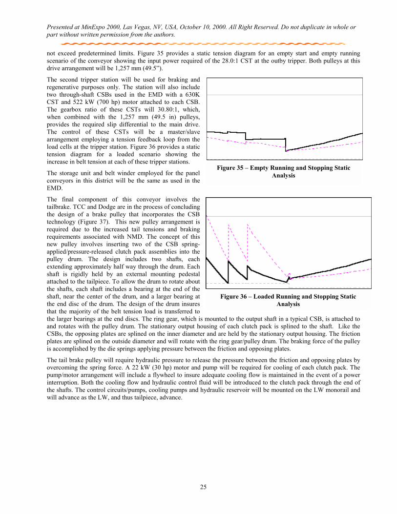
Presented at MinExpo 2000, Las Vegas, NV, USA, October 10, 2000. All Right Reserved. Do not duplicate in whole or part without written permission from the authors.
25
not exceed predetermined limits. Figure 35 provides a static tension diagram for an empty start and empty running scenario of the conveyor showing the input power required of the 28.0:1 CST at the outby tripper. Both pulleys at this drive arrangement will be 1,257 mm (49.5”).
The second tripper station will be used for braking and regenerative purposes only. The station will also include two through-shaft CSBs used in the EMD with a 630K CST and 522 kW (700 hp) motor attached to each CSB. The gearbox ratio of these CSTs will 30.80:1, which, when combined with the 1,257 mm (49.5 in) pulleys, provides the required slip differential to the main drive. The control of these CSTs will be a master/slave arrangement employing a tension feedback loop from the load cells at the tripper station. Figure 36 provides a static tension diagram for a loaded scenario showing the increase in belt tension at each of these tripper stations.
The storage unit and belt winder employed for the panel conveyors in this district will be the same as used in the EMD.
The final component of this conveyor involves the tailbrake. TCC and Dodge are in the process of concluding the design of a brake pulley that incorporates the CSB technology (Figure 37). This new pulley arrangement is required due to the increased tail tensions and braking requirements associated with NMD. The concept of this new pulley involves inserting two of the CSB spring-applied/pressure-released clutch pack assemblies into the pulley drum. The design includes two shafts, each extending approximately half way through the drum. Each shaft is rigidly held by an external mounting pedestal attached to the tailpiece. To allow the drum to rotate about the shafts, each shaft includes a bearing at the end of the shaft, near the center of the drum, and a larger bearing at the end disc of the drum. The design of the drum insures that the majority of the belt tension load is transferred to the larger bearings at the end discs. The ring gear, which is mounted to the output shaft in a typical CSB, is attached to and rotates with the pulley drum. The stationary output housing of each clutch pack is splined to the shaft. Like the CSBs, the opposing plates are splined on the inner diameter and are held by the stationary output housing. The friction plates are splined on the outside diameter and will rotate with the ring gear/pulley drum. The braking force of the pulley is accomplished by the die springs applying pressure between the friction and opposing plates.
The tail brake pulley will require hydraulic pressure to release the pressure between the friction and opposing plates by overcoming the spring force. A 22 kW (30 hp) motor and pump will be required for cooling of each clutch pack. The pump/motor arrangement will include a flywheel to insure adequate cooling flow is maintained in the event of a power interruption. Both the cooling flow and hydraulic control fluid will be introduced to the clutch pack through the end of the shafts. The control circuits/pumps, cooling pumps and hydraulic reservoir will be mounted on the LW monorail and will advance as the LW, and thus tailpiece, advance.
Figure 36 – Loaded Running and Stopping Static Analysis
Figure 35 – Empty Running and Stopping Static Analysis
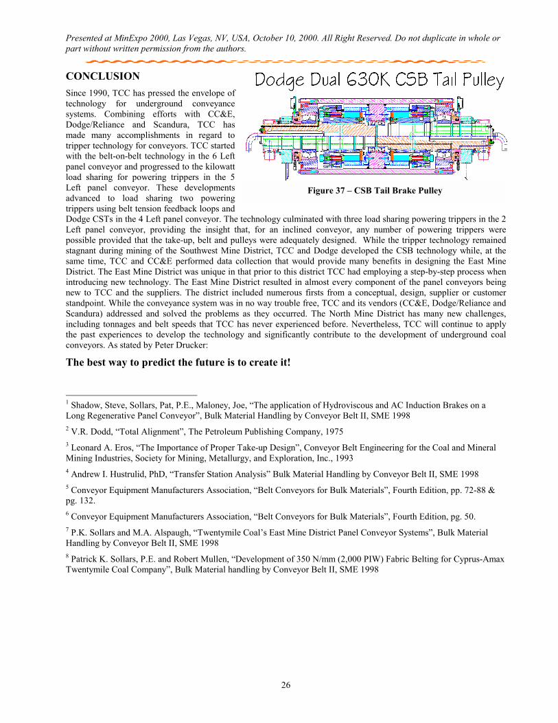
Presented at MinExpo 2000, Las Vegas, NV, USA, October 10, 2000. All Right Reserved. Do not duplicate in whole or part without written permission from the authors.
26
CONCLUSION Since 1990, TCC has pressed the envelope of technology for underground conveyance systems. Combining efforts with CC&E, Dodge/Reliance and Scandura, TCC has made many accomplishments in regard to tripper technology for conveyors. TCC started with the belt-on-belt technology in the 6 Left panel conveyor and progressed to the kilowatt load sharing for powering trippers in the 5 Left panel conveyor. These developments advanced to load sharing two powering trippers using belt tension feedback loops and Dodge CSTs in the 4 Left panel conveyor. The technology culminated with three load sharing powering trippers in the 2 Left panel conveyor, providing the insight that, for an inclined conveyor, any number of powering trippers were possible provided that the take-up, belt and pulleys were adequately designed. While the tripper technology remained stagnant during mining of the Southwest Mine District, TCC and Dodge developed the CSB technology while, at the same time, TCC and CC&E performed data collection that would provide many benefits in designing the East Mine District. The East Mine District was unique in that prior to this district TCC had employing a step-by-step process when introducing new technology. The East Mine District resulted in almost every component of the panel conveyors being new to TCC and the suppliers. The district included numerous firsts from a conceptual, design, supplier or customer standpoint. While the conveyance system was in no way trouble free, TCC and its vendors (CC&E, Dodge/Reliance and Scandura) addressed and solved the problems as they occurred. The North Mine District has many new challenges, including tonnages and belt speeds that TCC has never experienced before. Nevertheless, TCC will continue to apply the past experiences to develop the technology and significantly contribute to the development of underground coal conveyors. As stated by Peter Drucker:
The best way to predict the future is to create it! 1 Shadow, Steve, Sollars, Pat, P.E., Maloney, Joe, “The application of Hydroviscous and AC Induction Brakes on a Long Regenerative Panel Conveyor”, Bulk Material Handling by Conveyor Belt II, SME 1998 2 V.R. Dodd, “Total Alignment”, The Petroleum Publishing Company, 1975 3 Leonard A. Eros, “The Importance of Proper Take-up Design”, Conveyor Belt Engineering for the Coal and Mineral Mining Industries, Society for Mining, Metallurgy, and Exploration, Inc., 1993 4 Andrew I. Hustrulid, PhD, “Transfer Station Analysis” Bulk Material Handling by Conveyor Belt II, SME 1998 5 Conveyor Equipment Manufacturers Association, “Belt Conveyors for Bulk Materials”, Fourth Edition, pp. 72-88 & pg. 132. 6 Conveyor Equipment Manufacturers Association, “Belt Conveyors for Bulk Materials”, Fourth Edition, pg. 50. 7 P.K. Sollars and M.A. Alspaugh, “Twentymile Coal’s East Mine District Panel Conveyor Systems”, Bulk Material Handling by Conveyor Belt II, SME 1998 8 Patrick K. Sollars, P.E. and Robert Mullen, “Development of 350 N/mm (2,000 PIW) Fabric Belting for Cyprus-Amax Twentymile Coal Company”, Bulk Material handling by Conveyor Belt II, SME 1998
Figure 37 – CSB Tail Brake Pulley