two clamped pipe support connections for oil and gas
TRANSCRIPT

University of New Orleans University of New Orleans
ScholarWorks@UNO ScholarWorks@UNO
University of New Orleans Theses and Dissertations Dissertations and Theses
Fall 12-20-2019
Two Clamped Pipe Support Connections for Oil and Gas Two Clamped Pipe Support Connections for Oil and Gas
Brownfield Projects Brownfield Projects
Helen M. Claycomb University of New Orleans, [email protected]
Follow this and additional works at: https://scholarworks.uno.edu/td
Part of the Structural Engineering Commons
Recommended Citation Recommended Citation Claycomb, Helen M., "Two Clamped Pipe Support Connections for Oil and Gas Brownfield Projects" (2019). University of New Orleans Theses and Dissertations. 2688. https://scholarworks.uno.edu/td/2688
This Thesis is protected by copyright and/or related rights. It has been brought to you by ScholarWorks@UNO with permission from the rights-holder(s). You are free to use this Thesis in any way that is permitted by the copyright and related rights legislation that applies to your use. For other uses you need to obtain permission from the rights-holder(s) directly, unless additional rights are indicated by a Creative Commons license in the record and/or on the work itself. This Thesis has been accepted for inclusion in University of New Orleans Theses and Dissertations by an authorized administrator of ScholarWorks@UNO. For more information, please contact [email protected].

Two Clamped Pipe Support Connections for Oil and Gas Brownfield Projects
A Thesis
Submitted to the Graduate Faculty of the University of New Orleans in partial fulfillment of the
requirements for the degree of
Master of Science in
Engineering Civil and Environmental
by
Helen Mattei Claycomb P.E.
B.S. University of New Orleans, 2014
December, 2019

ii
Table of Contents List of Figures ........................................................................................................ iii List of Tables ......................................................................................................... iv Abstract ....................................................................................................................v Chapter 1 Introduction .............................................................................................1 1.1 Background Information ..........................................................................1 1.2 Greenfield and Brownfield Projects .........................................................2 1.3 Brownfield Projects - Additional Services ..............................................3 1.4 Typical Connections ................................................................................6 Chapter 2 Short Bolt and U-bolt Connections .........................................................9 2.1 Introduction ..............................................................................................9 2.2 Materials ................................................................................................18 2.3 Procurement, Fabrication, and Installation ............................................21 2.3.1Procurement and Fabrication .........................................................21 2.3.2 Surface Preparation of Existing Steel ...........................................22 2.3.3 Bolt Installation .............................................................................22 2.3.4 Surface Preparation of the Connections ........................................24 2.3.5 Coating of Connections.................................................................25 2.3 Maintenance ...........................................................................................27 2.4.1 Typical Maintenance Offshore .....................................................27 2.4.2 Corrosion Issues ............................................................................29 Chapter 3 Analysis Methods of Short Bolt and U-bolt Clamped Connections .....33 3.1 Short Bolt Connection............................................................................33 3.2 U-bolt Connection ..................................................................................35 Chapter 4 Future Study ..........................................................................................42 4.1 Summary and Conclusion ......................................................................42 4.2 Future Study ...........................................................................................42 References ..............................................................................................................43 Vita .........................................................................................................................46

iii
List of Figures
Figure 1: Plan View of Pipe Support Utilizing Short Bolt Connection .......................................... 9 Figure 2: Plan View of Short Bolt Connection Detail .................................................................. 10 Figure 3: Section View of Detail .................................................................................................. 10 Figure 4: Navis Works View of Pipe Support Utilizing Short Bolt Connection .......................... 11 Figure 5: Trapeze Pipe Support Utilizing Short Bolt Connection ................................................ 12 Figure 6: Navis Works View of Trapeze Pipe Support with Short Bolt Connection ................... 13 Figure 7: Elevation View of Pipe Support Utilizing U-bolt Connection ...................................... 14 Figure 8: Plan View of Pipe Support Utilizing U-bolt Connection .............................................. 14 Figure 9: Navis Works View of Pipe Support .............................................................................. 15 Figure 10: Elevation View of Pipe Support Utilizing U-bolt Connection .................................... 16 Figure 11: Navis Works View of Pipe Support ............................................................................ 16 Figure 12: Examples of Non-Structural U-bolts ........................................................................... 18 Figure 13: Plan View of Detail of Short Bolt Connection ............................................................ 19 Figure 14: Section View of Short Bolt Connection ...................................................................... 19 Figure 15: Plan View of U-bolt Connection Detail ...................................................................... 20 Figure 16: Elevation View of U-bolt Connection Detail .............................................................. 21 Figure 17: Process of Crevice Corrosion ...................................................................................... 30 Figure 18: Example of Corrosion at Pipe Support ........................................................................ 31 Figure 19: Another Example of Pipe Support Corrosion.............................................................. 31 Figure 20: Another Example of Corrosion at a Pipe Support ....................................................... 32 Figure 21: U-bolt Free Body Diagram .......................................................................................... 35 Figure 22: Case 2a from Roark's Table 14.1 ................................................................................ 38 Figure 23: Alternate U-bolt Analysis Free Body Diagram ........................................................... 41

iv
List of Tables
Table 1: Typical Coating Systems Used in the Atmospheric Zone .............................................. 26 Table 2: Guideline Survey Intervals ............................................................................................. 29 Table 3: Results from Example Calculations ................................................................................ 39 Table 4: Results from Factored Example Calculations ................................................................. 40

v
Abstract
In the oil and gas industry, brownfield projects focus on the modification of or addition to an
existing production facility that is fully operational and operating. Welding is typically avoided
on these projects. The drilling of holes in existing primary structural elements is also prohibited.
Clamped connections are often used when adding additional services in a brownfield project.
There are different types of clamped connections utilized when a new structural support must be
attached to an existing vertical structural pipe. The short bolt clamped connection is a well-
established connection and typically used on offshore projects. The U-bolt clamped connection is
an alternative connection, although its use in the offshore oil and gas industry is not as well
documented. The main drawback to using the U-bolt clamp connection is the lack of a well
researched and vetted design methodology. A preliminary analysis methodology is proposed in
this thesis. The material, fabrication, installation, and maintenance of both the short bolt
connection and U-bolt connection will also be discussed. The following thesis will end with
recommendations for moving forward.
Keywords: Clamped Pipe Supports, U-bolts

1
Chapter 1
Introduction
1.1 Background Information
Offshore oil fields are now located all over the world, with the most notable being found
in the North Sea, the Gulf of Mexico, the Campos and Santos Basins off the coasts of Brazil,
Newfoundland and Nova Scotia, several fields off the West African coast, South East Asia, and
Sakhalin, Russia. Drilling for oil in offshore oil fields first began in the Gulf of Mexico in 1947,
when the first offshore platform was installed in the Gulf. Since then, approximately 7,154
offshore platforms have been installed. Many of the fields that have been developed over the past
20-30 years in the Gulf are now maturing with many of the oldest facilities having been taken
out of service or operating under a reduced production rate, as the original field has played out.
Oil companies have tapped into satellite fields to mitigate production decline (Fort and Taxy),
since older facilities may have available capacity since their original production is no longer as
significant.
The Bureau of Safety and Environmental Enforcement (BSEE) is an agency in the
Department of Interior that enforces safety and environmental regulations for offshore energy
development. BSEE is involved in the approval of oil and gas plans, facilities, and operations. In
addition to monitoring compliance with regulations throughout the permitting process, the
agency also inspects the operation of offshore facilities to ensure compliance with regulations,
lease terms and statutes.
BSEE has a Gulf of Mexico Platform Structures Online Query, which is a database that
tracks all of the platforms that have been installed since 1947. This tool lists platform location,
structure name, business associate, installation date, removal date, water depth, and other

2
important information. According to BSEE’s online query, as of September 28, 2019, there were
approximately 1899 existing platforms in the Gulf of Mexico, many of which are producing
below their original capability.
In order to maximize all available capacity in a field, new drilling facilities utilize close-
by existing production facilities. When petroleum geologists locate an oil deposit in offshore oil
fields, an exploratory drill rig will drill a few temporary exploratory wells. Once the geologists
determine that the well is profitable, the oil company that owns the wells will drill a production
well. When drilling strikes the petroleum reservoir, the production casing caps off the well from
the surrounding reservoir. Explosives are then sent down the well to perforate the production
casing at different depths to allow the oil into the well. Pumps or water, oil or gas injections are
utilized to increase the reservoir pressure and bring the oil mixture to the surface of the drilling
platform, which is typically a mixture of crude oil, natural gas, water, and sediments. This
mixture is then processed on the drilling platform, if the platform has such capacity. If the
drilling platform does not have the capability, the mixture is transported via pipeline to the
nearest production facility that can handle the additional load (Lamb).
1.2 Greenfield and Brownfield Projects
Two types of projects exist in the oil and gas industry in the Gulf of Mexico: greenfield
and brownfield projects. Greenfield projects focus on new production facilities, whereas
brownfield projects focus on the modification of or addition to an existing production facility.
Brownfield projects are more common, especially in the Gulf of Mexico, due to the density of
existing drilling and production facilities. This is due to the high cost of building a brand-new
facility. The cost to build a new platform is incredibly expensive; therefore, instead of building a
new greenfield development, brownfield projects can be implemented.

3
A process that is increasingly being implemented in the Gulf of Mexico, due to its
economic advantages, is subsea tiebacks. Subsea tiebacks are one way of connecting a new well
to an existing facility. A subsea tieback is a process that connects new oil field discoveries to
near-by existing production facilities. This technology is an economical solution that maximizes
the life of existing production infrastructures. Due to much of the existing infrastructure already
being in place, projects can be fast tracked and brought into production quickly (Tieback Time).
Although new wells using subsea tiebacks do not require construction of new facilities, some
modifications and additions to the existing platform are necessary.
1.3 Brownfield Projects – Additional Services
It may be necessary to add additional piping, pipe supports, and process equipment on
existing platforms to accommodate the new production from the subsea tieback. During the
design process, the piping designer, piping engineer, and structural engineer work together to
ensure the design is feasible, safe, and minimizes clashes with existing equipment and piping on
an already congested facility. Typical offshore production piping ranges from ASME Class 150-
ASME Class 2500 (285-6170 psig). However, some production piping can have process fluid
flowing through them at much higher pressure and temperatures – anywhere from 100-500
degrees Fahrenheit. These pipes can carry oil, gas, water or other fluids. A pipe failure can
release toxic, flammable fluids, or hazardous chemicals into the environment. If piping fails, the
platform could have to have an extended shut-in, which is a large financial risk to the operators.
Most importantly, offshore personnel can be injured or killed. In order to prevent these pipe
failures from happening, proper design of pipe supports is critical.
The following overall design process is to be followed. When new piping is installed
during a brownfield project, such as a subsea tieback project, the piping designer routes the

4
piping in the most efficient and effective way and creates a set of piping isometric drawings. The
piping designers locate the existing structural steel near and/or along the piping where a new
pipe support can be installed. On most projects the piping designer will go offshore to
“walkdown” the isometric drawings. While offshore the designer will verify that there are no
clashes between the new components and the existing structure and assess the existing condition
of the structural steel. This is a critical step in the design process of integrating new components
into an existing platform.
Once the piping route is determined, the piping engineer must determine if the pipe itself
is adequate. This is achieved using pipe stress analysis software. The client has a set of
predetermined criteria that determines whether piping needs to be analyzed with pipe stress
analysis software. The piping engineer goes through the piping isometric drawings and
determines which piping fits the client’s criteria. The piping engineer then models the lines in the
pipe stress analysis software. The pipe is modeled, and a node is added wherever the pipe is
supported. The modeled piping is restrained at the anchor points, which is the location where the
piping connects into equipment. At that point, the piping is assumed to be rigid and restrained,
meaning that movement and rotation are prevented in all directions. The next step is to analyze
the piping for different load cases. The piping engineer must determine which load cases will be
applicable. The load cases include temperature, pressure, dead weight, module movement,
environmental conditions, steam hammer, surge, thrust, water hammer, and flow induced
vibrations. The piping engineers take all of these forces/loads into consideration when they do
pipe stress calculations. The pipe stress software is a tool used by the piping engineer to
determine if the proposed piping is adequate for the applied loading; results of the analysis
provide reaction forces at each support location. These reaction forces are given to the structural

5
engineer to be entered into the structural analysis program.
If the piping does not meet the client’s criteria to be analyzed with a pipe stress analysis
software, the structural engineer must use a structural analysis software or perform calculations
manually to determine the reaction forces at each support of the proposed piping to be added.
The structural engineer must calculate the dead weight and the design fluid weight based on the
piping isometrics and then input the loads into the structural analysis software. The structural
analysis program is used to ascertain the impact on the existing structural framing from
supporting the proposed new supports and piping using the applicable environmental loads.
Once the piping engineer has determined that the piping size and material is adequate,
the structural engineer can design the new pipe supports. On brownfield projects the structural
engineer should try to match the new steel shapes to the existing platform design. For example, if
the platform was originally designed with round pipe, the new supports should be made with
round pipe. When the engineer models the pipe supports, special care is needed in determining
what to model. It is inefficient to model the entire platform when designing new pipe supports.
However, if the new piping is being supported off an existing pipe rack, the new loads will affect
the existing steel. The engineer must decide to either model the existing steel and the new pipe
support or to model the new pipe support and then do local checks to determine if the existing
steel is structurally adequate. Once the engineer is satisfied with the support design, the
connection must be analyzed and designed.
1.4 Typical Connections
Pipe supports are either welded, bolted or clamped to existing structural members.
Welding is traditionally the preferred method of attaching supports to primary or secondary
framing members and is almost exclusively used on greenfield projects. Bolted and clamped

6
connections are rarely used on greenfield projects; new drilling and production facilities’
connections are almost 100% welded. However, on brownfield projects, welding is often avoided
due to hot work.
Brownfield projects are usually put into place on a facility that is fully operational and
operating. According to API RP 2201, hot work is defined as an operation that can produce
enough heat from a flame, spark, or other source of ignition, with sufficient energy to ignite
flammable vapors, gases, or dust and cause an explosion. Hot work operations include electric
arc and gas welding, chipping, flaming, grinding, gas cutting, abrasive blasting, brazing, and
soldering. Special procedures and permits are required when hot work is to be performed in
certain areas (4.) Because of the possible dangers associated with welding, specific requirements,
operations, and procedures have been set in place by BSEE. Per the Code of Federal Regulations,
welding may not take place within 10 feet of a wellbay, unless all producing wells in the wellbay
are shut-in. Welding may also not take place within 10 feet of a production area, unless the area
is shut in (30 CFR§250.113).
Welding on a working production facility is generally avoided to minimize shut-in time.
During a shut-in, all production on the platform is temporarily stopped. Shut-ins are necessary
for major modifications on a platform. However, shut-ins cost the client money. For example, if
a platform produces 100,000 barrels of oil per day and each barrel sells for $50, during a shut-in,
the company would lose $5 million a day.
Another disadvantage of welding on a working production facility is having to build a
Pressurized Welding Enclosure (PWE). A PWE is a fully enclosed area that is constructed to
create a safe welding environment. A PWE allows for hot work to be conducted in a small
isolated area while minimizing operational impacts on the rest of the platform. A PWE consists

7
of soft-sided panels, flooring, aluminum framed doors, atmospheric monitoring, programmable
logic control, positive pressure monitoring, and a ventilation system. To erect a PWE, floor
panels are set in place, and then the soft-sided flame-retardant wall panels are connected by thick
Velcro to conform to the geometry of the work area. All penetrations are then sealed to maintain
a positive pressure. To complete the system, atmospheric monitoring and positive pressure
monitoring are installed. A programmable logic controller system is used to control all aspects of
the hot work process. The positive pressure monitoring system measures the differential pressure
within the enclosure to maintain a positive pressure, so that the outside gases cannot enter the
PWE. Blowers supply clean fresh air into the PWE. PWEs are extremely helpful when a
platform shut-in is not possible. However, due to the high cost, the client will have a hard time
justifying the use of a PWE to weld out pipe supports. In addition, there is high risk to offshore
workers doing hot work.
The following cost is from SafeZone Safety Systems, LLC. The total cost includes
mobilization offshore to the platform, installation, single day of supporting hot work in the PWE,
and removal and demobilization from the facility.
Mobilization offshore to facility = $6,305
Installation, which is based off of a four man crew working 12 hour shift to
install a 12’x12’x12’ PWE = $6305
Daily cost to support hot work = $6305
PWE removal and demobilization from facility = $6305
Consumables (Carbon Fiber FR Felt/FR Velcro, Cleaner, Rope, etc.) = $2450
Total = $27,670
On projects where welding is not feasible or deemed too expensive, mechanical

8
connections must be developed. The classification and shape of the existing structural steel
element that the support is being attached to determines if the connection will be bolted or
clamped. In situations where the existing framing consists of primary steel, clamped connections
are preferred. Drilling holes in primary structural steel members decreases the load carrying
capacity of the existing member. Because reduction of capacity of existing primary structural
framing is not desired, bolted connections, which require additional holes, are not allowed. When
supporting off of secondary or tertiary steel, bolting through the beam flanges is accepted as the
norm. Wide flanges can be clamped around or bolted through. However, existing circular tube
steel must utilize clamped connections, regardless as to whether the existing tube is part of the
primary or secondary framing system.
When clamping around circular tube steel, two types of clamps can be used – short bolt
and U-bolt. These two clamps will be discussed in the following chapters.

9
Chapter 2
Short Bolt and U-bolt Clamped Connections
2.1 Introduction
This thesis will describe and compare the short bolt clamp connection and the U-bolt
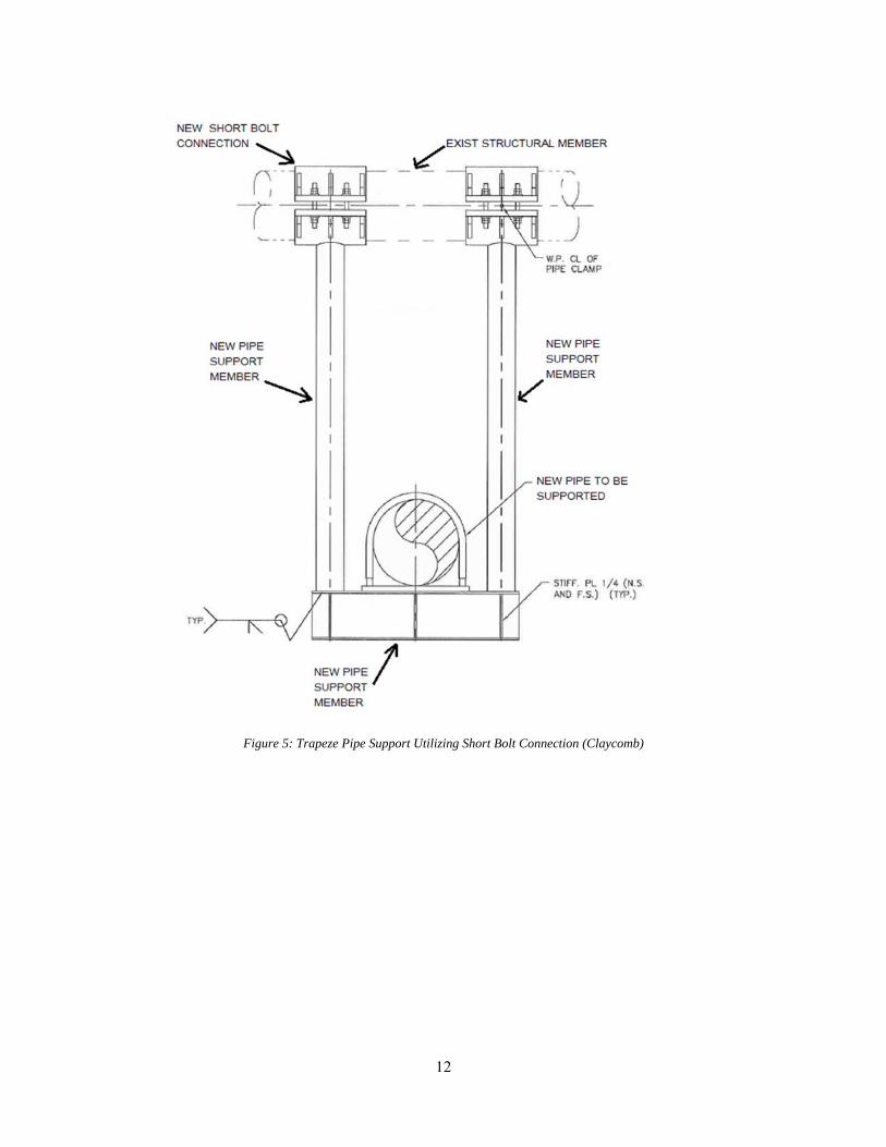
clamp connection. Figures 1 and 5 illustrate two different pipe support designs that utilize the
short bolt clamp connection. The first figure is a 2-D plan view of a pipe support featuring the
short bolt connection with the new piping supported by a cantilever support. Figures 2 and 3
show the connection details. The support is clamped around two existing vertical, circular
columns. Figure 4 is a 3-D rendering of this pipe support. The second pipe support design is a
trapeze style support. This design is the one usually used. Figure 5 depicts a 2-D elevation view
of the trapeze hanger pipe support. The new pipe support is clamped around and hanging from an
existing horizontal structural pipe. See Figure 6 for a 3-D rendering. Both of these designs utilize
the short bolt clamp connection when connecting to existing circular pipe structural members.
Figure 1: Plan View of Pipe Support Utilizing Short Bolt Connection (Claycomb)

10
Figure 2: Plan View of Short Bolt Connection Detail (Note: New bolts and bolt holes not shown) (Claycomb)
Figure 3: Section View of Detail (Claycomb)

11
Figure 4: Navis Works View of Pipe Support Utilizing Short Bolt Connection (Claycomb)
12
Figure 5: Trapeze Pipe Support Utilizing Short Bolt Connection (Claycomb)

13
Figure 6: Navis Works View of Trapeze Pipe Support with Short Bolt Connection (Claycomb)

14
Figures 7 and 10 illustrate two different pipe support designs that utilize the U-bolt clamp
connection. Figure 7 shows a 2-D elevation view of a trapeze pipe support that is clamped
around two existing vertical structural members. Figure 8 shows a 2-D elevation view. A 3-D
view is illustrated in Figure 9. Figure 10 depicts a similar cantilever pipe support.
Figure 7: Elevation View of Pipe Support Utilizing U-bolt Connection (Claycomb)
Figure 8: Plan View of Pipe Support Utilizing U-bolt Connection (Claycomb)

15
Figure 9: Navis Works View of Pipe Support (Claycomb)

16
Figure 10: Elevation View of Pipe Support Utilizing U-bolt Connection (Claycomb)
Figure 11: Navis Works View of Pipe Support (Claycomb)
The short bolt clamp is the current method used in the offshore oil and gas industry to
clamp around an existing vertical circular structural element. This connection stems from the

17
long and mid-bolt connection, which are used to support risers along the leg of a fixed platform.
This type of connection is well documented and widely accepted in the industry. There are
standard design procedures and methodology to assist engineers in the design of these
connections. The methodology behind the riser connection can easily be applied to the pipe
support connection.
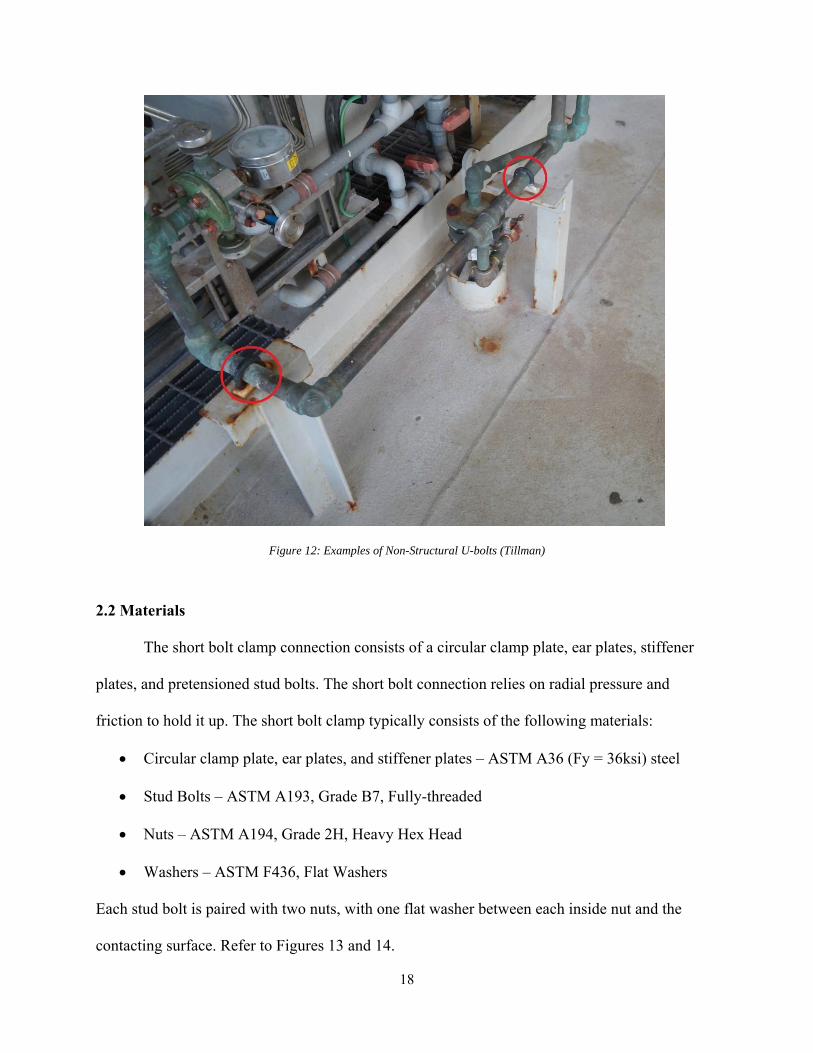
The U-bolt connection is typically used in the telecommunication industry and in the
nuclear power industry. In the offshore oil and gas industry, non-structural U-bolts are generally
used to secure new piping to an existing or new pipe rack or support (see Figure 12). These U-
bolts are not typically used as a structural connection to connect pipe supports to members of the
structural framing. There is no vetted analysis and design methodology for the U-bolt
connections.
Analysis and design methodologies for both types of clamped connections will be
covered in Chapter 3 of this thesis. As already mentioned, the short bolt clamped connection
procedure is well vetted. A preliminary analysis methodology for the U-bolt clamp connection
design will be proposed.
18
Figure 12: Examples of Non-Structural U-bolts (Tillman)
2.2 Materials
The short bolt clamp connection consists of a circular clamp plate, ear plates, stiffener
plates, and pretensioned stud bolts. The short bolt connection relies on radial pressure and
friction to hold it up. The short bolt clamp typically consists of the following materials:
Circular clamp plate, ear plates, and stiffener plates – ASTM A36 (Fy = 36ksi) steel
Stud Bolts – ASTM A193, Grade B7, Fully-threaded
Nuts – ASTM A194, Grade 2H, Heavy Hex Head
Washers – ASTM F436, Flat Washers
Each stud bolt is paired with two nuts, with one flat washer between each inside nut and the
contacting surface. Refer to Figures 13 and 14.

19
Figure 13: Plan View of Detail of Short Bolt Connection (Claycomb)
Figure 14: Section View of Short Bolt Connection (Claycomb)

20
The proposed U-bolt clamp connection consists of a pair of structural U-bolts and a steel
plate. The pipe support member (wide flange or angle) is shop-welded to the steel plate. In the
field the plate is attached to the existing circular tube steel with U-bolts. The main role of the U-
bolts is to provide a clamping force to hold the components together. Structural U-bolts are
shaped like the letter “U”. Both ends of the bolt feature screw threads, which are used to
adequately secure the pipe. The proposed clamp will typically consist of the following materials:
Plate – ASTM A36 (Fy = 36ksi)
Structural U-bolts – ASTM A36 or ASTM A307
Nuts – ASTM A563, Heavy Hex Head
Washers – ASTM F436, Flat Washers
Refer to Figures 15 and 16.
Figure 15: Plan View of U-bolt Connection Detail (Claycomb)

21
Figure 16: Elevation View of U-bolt Connection Detail (Claycomb)
2.3 Procurement, Fabrication, and Installation
2.3.1 Procurement and Fabrication
The total cost of the short bolt connection includes material procurement and fabrication.
The procurement cost depends on the design of the clamp. If the circular clamp plate, ear plate,
and stiffener plate are all different thicknesses, the fabrication yard will have to purchase three
separate plates. In this case, the fabrication yard would have to purchase six different items to
build the short bolt clamp.
The fabrication of the short bolt connection is more complex than that of the U-bolt
connection. First the clamp plate, ear plate, and stiffener plate must be cut to the correct size. The

22
circular clamp plate must then be rolled to the correct diameter as to fit around the existing
structural member. Then ear plates and stiffener plates must be welded to the circular clamp
plate. Lastly, stud bolt holes must be drilled into the ear plate.
Because the U-bolt connection consists of only four items, it’s procurement cost will be
lower than the short bolt clamp. The fabrication cost will also be less expensive as the U-bolt
clamp is much simpler than the short bolt. Once the fabrication yard has obtained the steel plate
and other materials, they must cut the connection plate to the correct size and drill U-bolt holes
in the correct location.
2.3.2 Surface Preparation of the Existing Structural Element
Before the new clamp connection is installed, the surface of the existing structural
member must be inspected and prepared. Per API RP 2A-WSD, where connections are designed
to be field installed, inspection methods should be developed to ensure proper installation in
accordance with design assumptions (114).
2.3.3 Bolt Installation
The structural performance of both the short bolt and the U-bolt clamp depends on the
installation. If the fit is too loose, the clamp’s capacity will be reduced. If the fit is too tight, the
clamp will be improperly installed.
In both the short bolt and U-bolt connection, the bolts are the primary means to transfer
the forces across the connection. Per ISO 19902-2007, “The pre-tensioned bolts induce a
continuous radial pressure on the substrate component, allowing friction on the contact surfaces,
which then allows shear forces to be transferred between the parts of the clamp. The bolts can
also provide a direct load path between the clamp parts” (152). The stud bolt in the short bolt
connection should be pretensioned to resist disengagement. The bolts need to be pretensioned so

23
the clamp does not open up or slip. The substrate member’s shear forces and bending moments
try to pry the clamp open, while axial forces and torsional moment tend to cause the clamp to
slip. The prying action on the clamp will be resisted by the extension in the bolts, and slippage
will be resisted by the friction developed at the clamp-to-member interface. This frictional
resistance is developed when the bolts are tightened. ISO 19902:2007 states that “because the
prying action tends to relieve the contact pressure and, thus, decrease the resistance against
slippage, the bolt prestress should correspond to the greater of the following two bolt forces: bolt
forces required to resist the prying (without separation); bolt forces required to prevent slippage”
(398).
To ensure that the bolts in the short bolt connection achieve their design tension, a
suitable installation technique is required. ISO 19902-2007 Section 15.2.8.3 recommends the
simultaneous use of hydraulic jacks or tensioners – one for each bolt. This technique, which
pretensions each bolt simultaneously, avoids uneven preload, which can occur with sequential
stressing techniques. The following stud tensioning systems are acceptable: Integra, Hire Torque,
Hydratight, SPX (QR or SST), Enerpac, Tristar or TSS. These systems use hydraulic bolt
tensioning technology that guarantees that each stud bolt develops the same load and provides a
uniform clamping force across the joint. All of the systems follow a specified general procedure.
First the hydraulic load cells are placed over each stud bolt. Next, the bolt tensioner’s puller is
threaded into each load cell. After the load cells are connected together with flexible hydraulic
hoses, a pre-set hydraulic pressure is applied. This pressure actuates the hydraulic load cells and
simultaneously places load on all of the stud bolts. Then a tommy bar is used to turn the locking
collar on each bolt tensioner. This places the nut firmly onto the joint surface. Finally, the
pressure is released and the bolt tensioning is complete. During the process of pre-tensioning, the

24
stud bolt acts like a spring. When the hydraulic pressure is applied, the bolt is stretched under
tension. When the pressure is released, the bolt tries to contract, which creates a clamping force
across the connection.
In U-bolt connections, the bolts are installed to a snug tight condition. As seen in Figure
15, the first nut on the U-bolt shall be tightened one half turn beyond a snug tight condition. The
second nut shall be tightened against the first nut to a snug tight condition. According to the
Specification for Structural Joints Using High-Strength Bolts, the snug tightened condition is
defined as “the tightness that is attained with a few impacts of an impact wrench or the full effort
of an ironworker using an ordinary spud wrench to bring the plies into firm contact” (RCSC 51).
According to the Guide to Design Criteria for Bolted and Riveted Joints, the snug condition
occurs, “when the turning of the nut was resisted by friction between the face of the nut and the
surface of the steel. Snug-tightening the bolts induces small clamping forces in the bolts. In
general, at the snug-tight condition the bolt clamping forces can vary considerably because
elongations are still within the elastic range” (Kulak 54). Snug tight bolts have no required
specified pretension, so a specific pretension cannot be assumed in a design/analysis method for
this type of clamped connection.
2.3.4 Surface Preparation of the Connections
The objective of surface preparation is to provide the necessary level of cleanliness
required for the designed coating system. According to NACE RP0176-2003 Section 12.2, the
following general steps should be taken: all surface imperfections must be removed prior to
surface preparations and the steel surface should be dry and contaminant-free prior to coating
(22). There are various types of surface preparation. Automated blast-cleaning machines are one
means of preparing plate, beams, and tubular members prior to fabrication. Air blast cleaning is
25
used when automated blast machines are not suitable, when cleaning is performed in the field, or
when maintenance is performed offshore (NACE RP0176-2003 22.)
Proper surface preparation is necessary for the longevity of both the short bolt clamped
connection and the U-bolt clamped connection. Installation of either clamped connection type
will require the same surface preparation steps.
2.3.5 Coatings of the Connections
Each oil company follows their own specification that details the coating process and
coating system. According to NACE RP0176-2003, high performance protective coating systems
must be used due to the extremely corrosive offshore environment. Most coating systems are
based on a highly inhibited prime coat that has “superior wetting and adhesion properties to
retard undercutting by rust, and to passivate the surface” (NACE RP0176-2003 24). Wash
primers, zinc-rich primers, and organic inhibitive primers are all commonly used prime coats.
Primer coats must be overcoated with topcoats.
Topcoats act as barriers that restrict water, oxygen, and chemical ions permeation.
Topcoats also provide added impact resistance, solvent resistance, and provide an aesthetically
pleasing finish. Chemically cured coatings, solvent-deposited, thermoplastic type coatings, and
thermal-sprayed aluminum are all types of topcoats. Table 1 lists typical coating systems used in
the Atmospheric Zone (NACE RP0176-2003 27).

26
Table 1: Typical Coating Systems Used in the Atmospheric Zone (NACE RP0176-2003)
Typically, pipe supports and their miscellaneous hardware are hot-dip galvanized. Hot
dip galvanizing is the process of coating fabricated steel by dipping it in a bath of molten zinc.
The process of hot-dip galvanizing is explained below.
Once the fabricated pipe supports arrive at the galvanizing facility, they must go through
surface preparation. As stated in the previous section, proper surface preparation is critical to the
longevity of any coating system, including galvanizing. Zinc will not adhere to or react with
unclean steel. Most galvanizing facilities have a three-step cleaning process. First the steel is
degreased. In this step, dirt, oil, and organic residues are removed. The second step consists of
placing the steel in an acidic pickling bath, which removes mill scale and iron oxide. The third
step includes fluxing. Fluxing removes any remaining oxides and coats the steel with a protective
layer to prevent any further oxide formation prior to galvanizing (Lindsley).
Once proper surface preparation has been performed, the steel is dipped into a hot molten
bath, which is at a temperature of 830℉ and consists of at least 98% zinc. While in the bath, zinc
flows over, around, and through (if the shape is hollow) the steel element. According to the
Lindsley, “while immersed in the kettle, the iron in the steel metallurgically reacts with the zinc

27
to form a series of zinc-iron intermetallic layers and an outer layer of pure zinc.” After the steel
is hot-dip galvanized, it must be inspected visually or by using a magnetic thickness gauge,
which verifies the coating thickness.
All of the components, in both the short bolt and U-bolt clamped connections, shall be
hot-dip galvanized. The process protects the steel from corrosion. According to the online
seminar, “the metallurgically-bonded zinc-iron alloy layers not only create a barrier between the
steel and the environment, but also cathodically protect the steel. The cathodic protection
offered by zinc means the galvanized coating sacrifices itself to protect the underlying base steel
from corrosion. The tightly adhered coating, which has bond strength of around 3,600 psi, is also
extremely abrasion-resistant, as the intermetallic layers are harder than the base steel.”
(Lindsley). After the pipe support and miscellaneous items have been hot-dip galvanized, an
additional layer of coating is applied. Although the pipe supports and their associated hardware
are coated in multiple layers of protection, regular monitoring and maintenance is necessary.
2.4 Maintenance
2.4.1 Typical Offshore Maintenance
Corrosion is defined as “the deterioration of a material, usually a metal, that results from
a reaction with its environment” (NACE RP0176-2003 1.) Offshore facilities are prime
candidates for corrosion as these structures are continuously exposed to sun, wind, sea spray, and
rain. Regular maintenance of offshore structures is required. Per ISO 19902:2007, steel offshore
structures require efficient corrosion control to ensure that the structural members’ strength is not
reduced by progressive corrosion degradation. Corrosion can affect the structural integrity of the
platform.
Corrosion of the platform topsides is typically controlled by the application of a

28
protective coating system. Maintenance coatings must be compatible with the original coating
system. The frequency and extent of recoating or touch-up work depends on the following:
“extent and location of corrosion damage on the structure, stress or loading of the affected
structure members, danger of spills and leaks from production piping and vessels, cost of
recoating work, including set-up charge, cost of deferred production and any equipment
downtime during coating operations, safety of personnel, and appearance factors” (NACE
RP0176-2003 27.)
According to API RP 2A-WSD, in-place surveys shall be performed during the life of the
platform. These surveys monitor the adequacy of the existing corrosion protection system. API
RP 2A-WSD has four levels of surveys. Level I survey consists of “a below-water verification of
performance of the cathodic protection system…and of an above-water visual survey to
determine the effectiveness of the corrosion protection system employed, and to detect
deteriorating coating systems, excessive corrosion, and bent, missing, or damaged members”
(API RP 2A-WSD 107). Bolt retightening or possible replacement should be included in the
surveys.
The frequency of these surveys depends upon the exposure categories of the platform for
both life safety and consequence of failure considerations (API RP 2A-WSD 108). Table 2,
which is taken from API RP 2A-WSD Table 14.4.2.1, gives a guideline for the timing between
surveys.

29
Table 2:Guideline Survey Intervals (API RP 2A-WSD)
The Code of Federal Regulations 49 Section 192.481, which covers monitoring
atmospheric corrosion control, states that the operator “must inspect each pipeline or portion of
pipeline that is exposed to the atmosphere for evidence of atmospheric corrosion…at least once
each calendar year. During inspections the operator must give particular attention to pipe at soil-
to-air interfaces, under thermal insulation, under disbanded coatings, at pipe supports, in splash
zones, at deck penetrations, and in spans over water” (49 CFR §192.481).
2.4.2 Corrosion Issues
There are various types of corrosion: uniform attack corrosion, galvanic corrosion,
intergranular corrosion, weld decay, pitting, concentration-cell corrosion, erosion corrosion,
selective leaching, dezincification, stress corrosion cracking, fretting corrosion, and cavitation
corrosion (Lindeburg 22-19). Pipe support corrosion is a common problem in the offshore oil
and gas industry.
Concentration-cell corrosion, also known as crevice corrosion or intergranular attack, is
the most common corrosion issue at pipe support locations. According to Lindeburg, crevice
corrosion, “occurs when a metal is in contact with different electrolyte concentrations. It usually
occurs in crevices, between two assembled parts, under riveted joints, or where there are scale
and surface deposits that create stagnant areas in a corrosive medium (22-19). A crevice is

30
formed where a pipe is supported by a structural member. If moisture gets trapped in the crevice,
first the protective coating will be attacked. Once coating failure has occurred, the pipe’s bare
steel will be in contact with water and oxygen (Young, Steve). Figure 17 illustrates the process
of crevice corrosion.
Figure 17: Process of Crevice Corrosion (Young, Steve)
Corrosion can occur at both the short bolt and the U-bolt clamped connection. There is no
indication in literature that one type of clamped connection corrodes first or faster than the other.
Corrosion is not a valid reason to select one type over the other.

31
Figure 18: Example of Corrosion at Pipe Support (Young, Steve)
Figure 19: Another Example of Pipe Support Corrosion (Britton)

32
Figure 20: Another Example of Corrosion at a Pipe Support (Tillman)

33
Chapter 3
Analysis Method of Short Bolt and U-bolt Clamped Connections
3.1 Short Bolt Connection
ISO 19902:2007 15.3.4.1 states that “the internal forces in the substrate components and
in the attached members generally translate into the following forces on clamp:
a) shear forces and bending moments that tend to separate the clamp pieces
b) axial forces and torque along the clamp axis that tend to produce relative slippage
between the clamp and the substrate members.
Prestressed clamps transfer forces by radial bearing contact and friction at the clamp to
member interface. Therefore, the long-term bolt forces shall be of such magnitude as to ensure
that the contact pressure induced by the bolts is not overcome by the separation action due to the
forces applied to the clamp. At the same time, the contact pressure shall develop sufficient
friction to resist slippage. Similar to grouted connections, the interaction of the bending moments
and shear forces with the axial force, all acting at the free ends of the clamp, tends to enhance the
slip strength of the clamp. Therefore, it is conservative to assume that the separation and slip
forces do not interact” (ISO 19902:2007 150).
Short bolt clamps are designed to endure and transfer the forces and moments in the
members attached to the clamp and substrate member. “The design process involves selecting the
size, number, distribution and preload of the bolts, in conjunction with a clamp configuration
such that the clamp shall sustain and transfer the forces in the clamped and attached members
without opening, slipping or crushing the clamped members” (ISO 19902:2007 153)
The following method of design is based on ISO 19902:2007. Once the forces and
reactions have been calculated, either by hand or by a structural analysis computing system, the

34
first step in the design procedure is to check prying. The goal of this step is to find the minimum
pre-tension to resist prying. This calculation is done by determining the prying moment,
calculating the force on the end bolt pair induced by the prying moment, calculating the force on
the end bolt pair induced by the forces in the added member, and by determining the minimum
required bolt pre-tension to resist prying. The bolt pretension must be at least 10 kips. Then the
total pre-tension load can be calculated.
The second step is to check slip. This is done by first calculating the acting slip, the
acting slip stress, and then the slip strength. The slip strength must be calculated by using the
bolt pre-tension, which was selected in the first step. Compare the acting slip with the slip
strength. If the acting slip is greater than the slip strength, then the bolt pre-tension must be
increased until it is large enough to adequately resist the acting slip.
The third step is to check the bolts according to the AISC Steel Manual for shear and
tension. Minimum bolt spacing and minimum edge distance must also be checked. The ear plate
must be checked for bearing and for shear rupture at the bolt holes.
The fourth step is to check the ear plate for bending. Bending in the ear plate should be
checked according to Roark’s formulas for a rectangular plate with three edges fixed and one
edge free. Bending of the combined section (ear plate and stiffeners on one half of the clamp)
should be checked for the moment caused by half of the total bolt load. The ear plate should be
treated as a cantilever beam that is fixed at the clamp plate and loaded at the centers of the bolt
holes.
The fifth step is to check the clamped member according to Roark’s formulas for thin or
thick-walled vessels. The acting radial pressure must be calculated. Then determine if the
clamped member is thin or thick-walled. If the member is thin-walled, the collapsing pressure

35
and the circumferential (hoop) stress must be checked. If the member is thick-walled, the
bursting pressure and the circumferential stress must be checked.
The sixth step is to check the circular clamp plate for bending due to My and Mz. Each
clamp half must resist half of My and half of Mz. The clamp also must be checked for tension.
3.2 U-bolt Connection
Unlike the short bolt clamped connection, the U-bolt connection does not have a vetted
design procedure. This thesis will attempt to produce a guideline for designing the U-bolt
connection for a cantilever type pipe support. U-bolts are typically manufactured from A36 steel,
which is a lesser grade than the structural bolts in the short bolt connection. As already
mentioned, the U-bolt connection will be designed considering a snug tight condition. Thus, the
connection will not ensure a specific U-bolt pretension.
If a specified pretension on the U-bolt can not be relied on, Figure 21 provides an
idealization of the connection plate’s loading. A few simplifying assumptions must be made. It
is assumed that the pipe support beam and the base plate have coincident centroids.
Figure 21: U-bolt Free Body Diagram (Claycomb)
The top U-bolt will be in tension, while the bottom U-bolt cannot be relied on to be the

36
compressive force resisting the top U-bolt’s tension. By rules of static equilibrium, the tension in
the top bolt must equal the compressive resultant in the bottom of the plate. It is also assumed
that a triangular pressure distribution across the length of the base plate in the direction of the
applied moment will result on the base plate. The triangular pressure distribution will have the
maximum pressure on the compressive side and zero pressure on the tensile side.
The gravity weight of the piping acting at a distance away from the U-bolt connection
will cause a moment. This moment must be resisted by the tension in the top U-bolt multiplied
by the moment arm, which is the distance from the tension bolt to the centroid of the triangular
pressure distribution. The plate will be pressed into the supporting vertical, which in this case is
the circular pipe. The contact area is a function of tension as summation of forces in the x-
direction must be zero. The contact area is the length A multiplied by the width b.
This is an iterative process. To start, a length A of the triangular pressure distribution is
assumed. The moment arm is dependent on the A dimension; therefore, once A is set, the
moment arm is calculated. Once the moment arm is set, the tension in the U-bolt can be
calculated.
The next step is to determine the force in the compression U-bolt. The compression force
is assumed to be the contact area multiplied by half of the maximum pressure on the compressive
side. The contact area is equal to the contact width multiplied by the length of the triangular
pressure distribution. The contact width b, which is determined using Roark’s Case 2a from the
Formulas for stress and strain due to pressure on or between elastic bodies (Table 14.1), is a
function of the tension in the U-bolt.
Hertzian contact theory is used to calculate the contact width b, involved in the U-bolt
connection. Hertzian contact stress is a description of the stresses between two bodies in contact.

37
In Hertz’s classical theory, which is primarily based on non-adhesive contact, it is assumed that
no tension force is allowed to occur within the contact area. According to Zhu, the following
assumptions are made in determining the solutions of Hertzian contact problems: “the strains are
small and within the elastic limit, each body can be considered an elastic half-space, i.e., the area
of contact is much smaller than the characteristic radius of the body, the surfaces are continuous
and non-conforming, and the bodies are in frictionless contact” (Zhu.) The theory of contact
between elastic bodies can be used to find contact areas. Zhu discusses five types of commonly
used Hertzian contact solutions: contact between a sphere and an elastic half-space, contact
between two spheres, contact between two cylinders with parallel axes, contact between a rigid
cylinder and an elastic half-space, and contact between a rigid conical indenter and an elastic
half-space. The fifth solution can be directly applied to the U-bolt connection, provided that the
cylinder (the vertical support) remains perfectly rigid (does not deform) during loading.
The U-bolt connection plate and compressive zone can be represented by a cylinder
pushed into a flat plate. Warren Young gives the formulas for the elastic stress and deformation
produced by pressure between bodies of various forms and for the dimensions of the circular,
elliptical, or rectangular area of contact formed by the compressed surfaces (Young, Warren
703). These equations are based off of Hertz’s theory. Hertz assumed that the length of the
cylinder and dimensions of the plate are to be infinite. An analysis was done on a typical U-bolt
connection to determine if Hertz’s theory could be used to accurately analyze the U-bolt
connection.

38
Figure 22: Case 2a from Roark's Table 14.1 (Young, Warren)
The P (total load) from Figure 22 is calculated as two multiplied by the tension in the U-
bolt. The load per unit length is calculated as the total load divided by the tributary length of the
pipe. A length of twenty feet is conservatively used as the tributary length of the piping. After
the load per unit length is calculated, the contact width can be calculated from the formula in
Figure 22. Then the maximum pressure on the compressive side of the base plate can be
calculated. It is assumed to be 75% of the yield stress, which is from AISC 9th edition, Equation
F2-1 (AISC 5-48).
It is expected that the tension in the top bolt will equal the compression resultant force in

39
the bottom portion of the plate as it pushes against the existing vertical support.
A few example calculations were performed to prove these proposed guidelines. The
results can be found in the Table 3. These results were not expected. The tension in the U-bolt
should equal the compression resultant. Based on these results, it was determined that the
Hertzian contact width is too small to develop the necessary resisting moment. Hertz’s
assumption that the cylinder remains perfectly rigid is not an accurate prediction of actual
behavior.
Table 3: Results from Example Calculations
Assumed A Arm T P p bcontact
area Cinches inches kips kips kips/inch inch inch^2 kips
1 10.67 0.56 1.12 0.0047 0.0018 0.0018 0.022 10.33 0.58 1.16 0.0048 0.0019 0.0037 0.053 10 0.6 1.2 0.0019 0.0019 0.0057 0.086 9 0.67 1.33 0.0056 0.002 0.012 0.168 8.33 0.72 1.44 0.006 0.0021 0.017 0.2210 7.67 0.78 1.56 0.0065 0.0022 0.02 0.2912 7 0.86 1.71 0.0071 0.0023 0.027 0.37
A finite element analysis (FEA) can be used to obtain a more precise width of the contact
area to accurately predict the actual connection behavior. A few more example calculations were
performed to determine what would happen if the contact width was multiplied by various whole
number factors, thus modifying the Hertzian contact area. The results are listed in Table 4. By
increasing the contact area, by the use of a constant Cb, to modify the width b, the results
accurately predict the actual connection behavior. The vertical pipe support is not acting as a
rigid, non-deforming cylinder. Table 4 indicates that a wider breadth than given using Hertzian
theory results in a more realistic behavior. The proposed modifier Cb could be calculated using
FEA and would be a function of thickness and material of both the vertical pipe structural

40
framing member and the U-bolt steel plate.
Table 4: Results from Factored Example Calculations
Assumed A Cb
Factor b'Contact
Area' T C inches inch inch^2 kips kips
2 2 0.0038 0.0076 0.58 0.10 2 3 0.0057 0.0114 0.58 0.15 2 4 0.0076 0.0152 0.58 0.21 2 11 0.209 0.0418 0.58 0.56 3 8 0.0152 0.0456 0.6 0.62 6 4 0.008 0.048 0.67 0.65
An alternate method of analysis is suggested, which relies on a minimum tension in the
U-bolts to be attained. Snug tight bolt tightening cannot be used for a required pretension in the
U-bolt. Standard materials for U-bolts do not allow for tightening procedures which ensure a
particular level of pretension attainment. If minimum pretension in the U-bolt is attained, Figure
23 provides an idealization of the connection plate’s loading. In this figure, the tension and
compression forces are at the center of gravity of the top and bottom U-bolts. This is a design
analysis that is typical for a high strength bolted connection. The moment due to the gravity load
is resisted by the tension in the U-bolt multiplied by the vertical distance between the set of U-
bolts. The summation of forces in the y direction must equal zero. The maximum tension and the
maximum shear in the U-bolts must be checked against the allowable tension and shear per
AISC, 9th edition. For this design analysis methodology to be valid, the U-bolt must be custom
made of grade A325 steel and the bolt tightening must follow that of high strength bolt
procedures. These changes would negate any cost savings.
Once the U-bolts have been determined to be adequate for the anticipated tension and
shear, caused by the moment, the base plate shall be checked for weak axis bending. In both of
the U-bolt analyses, friction must be regarded. The frictional forces in the connection will resist

41
the vertical load.
Figure 23: Alternate U-bolt Analysis Free Body Diagram (Claycomb)
In both the proposed U-bolt analysis and the alternate U-bolt analysis, the structural
vertical member must be checked local crushing. Similarly to step five of the short bolt design
procedure, the clamped member must be analyzed according to Roark’s formulas for thin or
thick-walled vessels. The acting radial pressure must be calculated. Then determine if the
clamped member is thin or thick-walled. If the member is thin-walled, the collapsing pressure
and the circumferential (hoop) stress must be checked. If the member is thick-walled, the
bursting pressure and the circumferential stress must be checked.

42
Chapter 4
Future Study
4.1 Summary and Conclusion
In conclusion, clamped connections are an important design component when adding
additional services in a brownfield project. When a new structural support must be attached to an
existing vertical structural pipe, a clamped connection must be utilized. The short bolt clamped
connection has a well-vetted design methodology. The U-bolt clamped connection is an
alternative connection, which is not well researched or documented. In this thesis, a preliminary
design methodology for the U-bolt connection was discussed. Results indicate that the vertical
pipe support is not acting as a rigid, non-deforming cylinder. Therefore, the Hertzian contact area
calculations are not truly applicable. These results prove that this preliminary design
methodology needs further study in order to determine the required modification factor Cb.
4.2 Future Study
To finalize the design methodology of the proposed U-bolt connection, a Finite Element
Analysis (FEA) sensitivity study should be done. By using a FEA software package, the U-bolt
plate and the vertical structural pipe materials and thicknesses could be more accurately
analyzed. The FEA software will allow the user to analyze each individual element. The Hertzian
width modifier Cb could be determined for all cases. Once this FEA study yields a table for the
Hertzian width modifier Cb, the design procedure given in Chapter 3.2 of this thesis can be
reliably followed in the design of the U-bolt connection.

43
References
AISC Manual of Steel Construction, Allowable Stress Design. 9th Edition. American Institute of
Steel Construction, Chicago, November 1989.
Britton, Jim. “New Paint Preservation Technologies for Offshore & Marine Equipment.” 1998.
From NAVY Conference. www.stoprust.com/technical-library-items/30-marine-paint-
preservation
Claycomb, Helen. 2-D and 3-D Figures of clamped pipe supports. 2019. Author’s personal
collection.
Cody, Brian. Photo of Big Foot Being Towed into the Gulf. Big Foot passes through, Port Aransas
South Jetty, 30 January 2018, www.portasouthjetty.com/articles/big-foot-passes-through/.
Corrosion Control of Steel Fixed Offshore Structures Associated with Petroleum Production.
NACE International Standard Recommended Practice. RP0176-2003, NACE
International, Houston, Texas.
Fort, Vincent and Stephane Taxy. “Topsides modifications approach optimizes brownfield
projects.” Offshore Magazine, 7 July 2016, www.offshore-mag.com/field-
development/article/16754798/topsides-modifications-approach-optimizes-brownfield-
projects, Accessed 28 September 2019.
Kulak, Geoffrey L., et al. Guide to Design Criteria for Bolted and Riveted Joints. Second Edition.
Chicago. American Institute of Steel Construction, Inc. 2001.
Lamb, Robert. “How Offshore Drilling Works”. 10 September 2008. How Stuff Works.
https://science.howstuffworks.com/environmental/energy/offshore-drilling4.htm.
Accessed 28 September 2019.

44
Lindeburg, Michael R. Civil Engineering Reference Manual for the PE Exam. 15th Edition.
Professional Publications, Inc., 2015, Belmont, California.
Lindsley, Melissa. “Sustainable Development and Hot-Dip Galvanizing – online Galvanize It!
Seminar” American Galvanizers Association. Revised in April 2017.
https://galvanizeit.org/sustainable-development-hot-dip-galvanizing-online-seminar/.
Nielsen, James, Photo of Shell’s Ursa platform in the Gulf. Shell kicks off production with
Kaikias in Gulf of Mexico. Chron, 1 June 2018,
https://www.chron.com/business/energy/article/Shell-kicks-off-production-with-Kaikias-
in-Gulf-12959195.php.
“Oil and Gas and Sulphur Operations in the Outer Continental Shelf,” Title 30, Code of Federal
Regulations, Pt. 250.113. 2019 Edition.
Petroleum and natural gas industries – Fixed steel offshore structures, International Standard
19902. First Edition, 2007, ISO, Switzerland.
Platform Structures Online Query, Bureau of Safety and Environmental Enforcement.
https://www.data.bsee.gov/Platform/PlatformStructures/Default.aspx. Accessed 28
September 2019.
Recommended Practice for Planning, Designing, and Constructing Fixed Offshore Platforms-
Working Stress Design, API Recommended Practice 2A-WSD (RP 2A-WSD). 21st Ed.,
December 2000. Errata and Supplement 1, December 2002. Errata and Supplement 2,
September 2005. Errata and Supplement 3, October 2007. American Petroleum Institute,
Washington, DC.
Safe Hot Tapping Practices in the Petroleum and Petrochemical Industries. API Recommended

45
Practice 2201 (API RP 2201). 5th Ed, July 2003. American Petroleum Institute,
Washington, DC.
Specification for Structural Joints Using High-Strength Bolts, Research Council on Structural
Connections. 1 August 2014. Prepared by RCSC Committee A.1, RCSC, Chicago.
Tillman, Jason. Photo of pipe support in the Gulf of Mexico. 2019. Author’s personal collection.
“Tieback Time,” Offshore Technology. 28 February 2007, www.offshore-
technology.com/features/feature1033/, Accessed 28 September 2019.
“Transportation of Natural and Other Gas by Pipeline: Minimum Federal Safety Standards,”
Title 49, Code of Federal Regulations, Pt. 192.481. 2019 Edition.
Young, Steve. “Why These 5 Common Pipe Support Designs Fail.” Deepwater Corrosion
Services Inc., 2019, https://stoprust.com/technical-library-items/why-these-5-common-
pipe-support-designs-fail/.
Young, Warren C. and Richard G. Budynas. Roark’s Formulas for Stress and Strain. 7th Edition.
McGraw-Hill, 2002. New York, New York.
Zhu, Xiaoyin. “Tutorial on Hertz Contact Stress.” 1 December 2012.
https://wp.optics.arizona.edu/optomech/wp-content/uploads/sites/53/2016/10/OPTI-521-
Tutorial-on-Hertz-contact-stress-Xiaoyin-Zhu.pdf.

46
Vita
Helen Mattei Claycomb, P.E. was born in Metairie, Louisiana in 1993. She completed her
primary education at St. Mary’s Dominican High School in 2011, and received a Bachelor’s of
Science (B.S.) degree in Engineering from the Civil and Environmental Engineering Department
at the University of New Orleans (UNO) in December 2014. Immediately after her graduation,
she began working full time at an engineering consulting firm and taking night classes to pursue
her Master’s of Science (M.S.) in Engineering.