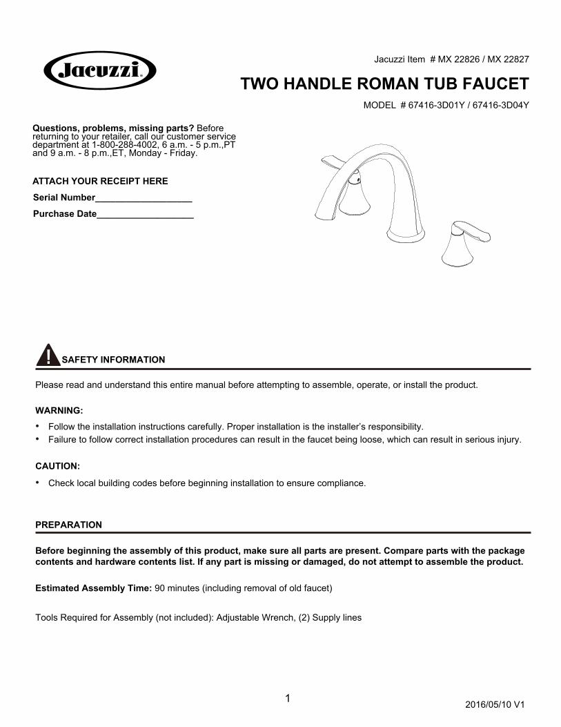
two handle roman tub faucet
TRANSCRIPT
1
Questions, problems, missing parts? Before returning to your retailer, call our customer service department at 1-800-288-4002, 6 a.m. - 5 p.m.,PTand 9 a.m. - 8 p.m.,ET, Monday - Friday.
TWO HANDLE ROMAN TUB FAUCETJacuzzi Item # MX 22826 / MX 22827
MODEL # 67416-3D01Y / 67416-3D04Y
ATTACH YOUR RECEIPT HERE
Serial Number___________________
Purchase Date___________________
2016/05/10 V1
SAFETY INFORMATION
Please read and understand this entire manual before attempting to assemble, operate, or install the product.
WARNING:
• Follow the installation instructions carefully. Proper installation is the installer’s responsibility. • Failure to follow correct installation procedures can result in the faucet being loose, which can result in serious injury.
CAUTION: • Check local building codes before beginning installation to ensure compliance.
PREPARATION
Before beginning the assembly of this product, make sure all parts are present. Compare parts with the package contents and hardware contents list. If any part is missing or damaged, do not attempt to assemble the product.
Estimated Assembly Time: 90 minutes (including removal of old faucet)
Tools Required for Assembly (not included): Adjustable Wrench, (2) Supply lines
2
ASSEMBLY INSTRUCTIONS
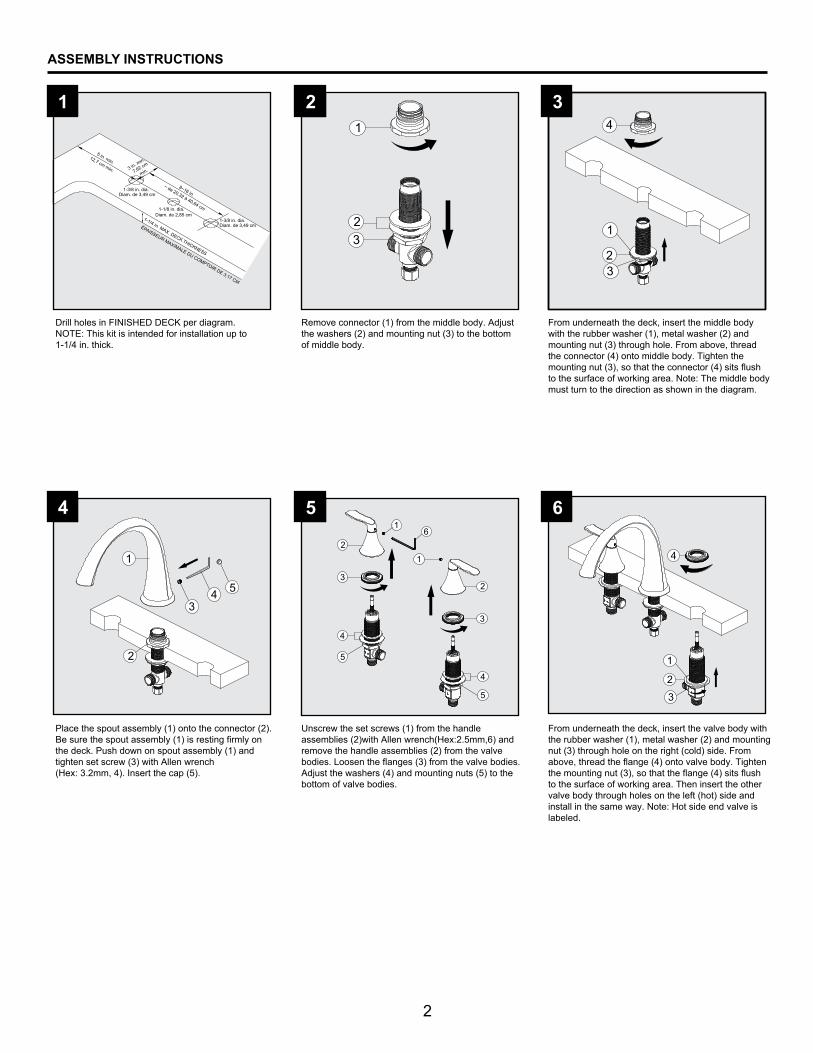
From underneath the deck, insert the middle body with the rubber washer (1), metal washer (2) and mounting nut (3) through hole. From above, thread the connector (4) onto middle body. Tighten the mounting nut (3), so that the connector (4) sits flush to the surface of working area. Note: The middle body must turn to the direction as shown in the diagram.
2 3
Drill holes in FINISHED DECK per diagram. NOTE: This kit is intended for installation up to 1-1/4 in. thick.
1
Place the spout assembly (1) onto the connector (2). Be sure the spout assembly (1) is resting firmly on the deck. Push down on spout assembly (1) and tighten set screw (3) with Allen wrench(Hex: 3.2mm, 4). Insert the cap (5).
Unscrew the set screws (1) from the handle assemblies (2)with Allen wrench(Hex:2.5mm,6) and remove the handle assemblies (2) from the valve bodies. Loosen the flanges (3) from the valve bodies. Adjust the washers (4) and mounting nuts (5) to the bottom of valve bodies.
4 5
From underneath the deck, insert the valve body with the rubber washer (1), metal washer (2) and mounting nut (3) through hole on the right (cold) side. From above, thread the flange (4) onto valve body. Tighten the mounting nut (3), so that the flange (4) sits flush to the surface of working area. Then insert the other valve body through holes on the left (hot) side and install in the same way. Note: Hot side end valve is labeled.
6
5 in. min.
8~16 in.
3 in. min.
1-1/4 in. MAX. DECK THICKNESS
1-1/8 in. dia.
1-3/8 in. dia.
Remove connector (1) from the middle body. Adjust the washers (2) and mounting nut (3) to the bottom of middle body.
2
1
4
3
5
2
1
4
3
5
12,7 cm min. 7,62 cm
min.
Diam. de 3,49 cm
~ de 20,32 à 40,64 cmDiam. de 2,85 cm
1-3/8 in. dia. Diam. de 3,49 cmÉPAISSEUR MAXIMALE DU COMPTOIR DE 3,17 CM
23
4
1
2
34 5
1
23
1
4
23
1
2
34 5
2
1
4
3
6

3
ASSEMBLY INSTRUCTIONS
8
Place the handle assembly (1) onto the right (cold) valve (2). Then thread the handle seat (3) onto the flange (4). Place the set screw (5) into handle assembly (1) and tighten set screw (5) with Allen wrench (Hex: 2.5mm, 6), Place the other handle assembly onto the left (hot) valve and install the same way.
7
Turn on hot and cold water supplies and flush water lines for one minute. After flushing,turn the handlesall the way off to shut off the water.
10
Connect a 1/2 in. IPS faucet connector (not included) to the water supplies underneath the sink using wrenches (not included).NOTE: Refer to the local plumbing codes for permissible types of water supply connectors.
9
2
13
2
5
1
4
6
1
2
34
Connect the flexible water supply hose (1) to the bottom of valve bodies (2) as show. Align middle body (3) in a position which will allow maximum clearance to connect hoses. Carefully bend the hoses to fit available space. Carefully thread the hose couplings to the sides of the middle body (3). Tighten nut (4) securely with wrench.
4
ASSEMBLY INSTRUCTIONS
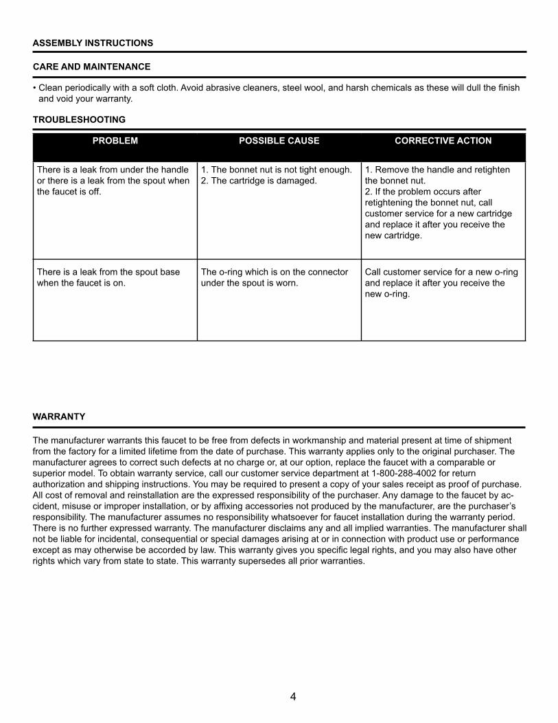
TROUBLESHOOTING
PROBLEM POSSIBLE CAUSE CORRECTIVE ACTION
There is a leak from under the handle or there is a leak from the spout when the faucet is off.
There is a leak from the spout base when the faucet is on.
1. The bonnet nut is not tight enough.2. The cartridge is damaged.
The o-ring which is on the connector under the spout is worn.
1. Remove the handle and retighten the bonnet nut.2. If the problem occurs after retightening the bonnet nut, call customer service for a new cartridge and replace it after you receive the new cartridge.
Call customer service for a new o-ring and replace it after you receive the new o-ring.
The manufacturer warrants this faucet to be free from defects in workmanship and material present at time of shipment from the factory for a limited lifetime from the date of purchase. This warranty applies only to the original purchaser. The manufacturer agrees to correct such defects at no charge or, at our option, replace the faucet with a comparable or superior model. To obtain warranty service, call our customer service department at 1-800-288-4002 for return authorization and shipping instructions. You may be required to present a copy of your sales receipt as proof of purchase. All cost of removal and reinstallation are the expressed responsibility of the purchaser. Any damage to the faucet by ac-
, are the purchaser’s responsibility. The manufacturer assumes no responsibility whatsoever for faucet installation during the warranty period. There is no further expressed warranty. The manufacturer disclaims any and all implied warranties. The manufacturer shall not be liable for incidental, consequential or special damages arising at or in connection with product use or performance
rights which vary from state to state. This warranty supersedes all prior warranties.
WARRANTY
CARE AND MAINTENANCE
• and void your warranty.

5
For replacement parts, call our customer service department at 1-800-288-4002, 6 a.m. - 5 p.m., PT and 9 a.m. - 8 p.m.,ET, Monday - Friday
REPLACEMENT PARTS LIST
PART DESCRIPTION PART# 1
34567
Printed in China
8910
11
12
1413
15
2
1617
18
19
01
02
030405060708
09
10
1211
13
14
15
16
1718
19
Set Screw RP50002Handle assembly RP13444*Connector RP50183Bonnet nut RP70058Cartridge H RP20035Cartridge C RP20036Flange RP70540Rubber washer RP64023Metal washer RP64024Nut RP56014
Set Screw RP50054
Cap RP10067*O-Ring RP60056Connector RP70459Rubber washer RP64035Metal washer RP64036Nut RP56088O-Ring RP60094Hose RP70042