two-mode model for metal-dielectric guided-mode resonance
TRANSCRIPT
HAL Id: hal-01390841https://hal.archives-ouvertes.fr/hal-01390841
Submitted on 2 Nov 2016
HAL is a multi-disciplinary open accessarchive for the deposit and dissemination of sci-entific research documents, whether they are pub-lished or not. The documents may come fromteaching and research institutions in France orabroad, or from public or private research centers.
L’archive ouverte pluridisciplinaire HAL, estdestinée au dépôt et à la diffusion de documentsscientifiques de niveau recherche, publiés ou non,émanant des établissements d’enseignement et derecherche français ou étrangers, des laboratoirespublics ou privés.
Two-mode model for metal-dielectric guided-moderesonance filters
Christelle Tuambilangana, Fabrice Pardo, Emilie Sakat, Patrick Bouchon,Jean-Luc Pelouard, Riad Haïdar
To cite this version:Christelle Tuambilangana, Fabrice Pardo, Emilie Sakat, Patrick Bouchon, Jean-Luc Pelouard, et al..Two-mode model for metal-dielectric guided-mode resonance filters. Optics Express, Optical Societyof America - OSA Publishing, 2015, 23 (25), p. 31672-31681. �10.1364/OE.23.031672�. �hal-01390841�

Two-mode model for metal-dielectricguided-mode resonance filters
Christelle Tuambilangana,1,2 Fabrice Pardo,2,∗ Emilie Sakat,1,2Patrick Bouchon,1 Jean-Luc Pelouard,2 and Riad Haıdar1
1MiNaO Joint Lab., ONERA-The French Aerospace Lab, F-91761 Palaiseau, France2MiNaO Joint Lab., LPN, CNRS, Universite Paris-Saclay, route de Nozay, F-91460
Marcoussis, France∗[email protected]
Abstract: Symmetric metal-dielectric guided-mode resonators (GMR)can operate as infrared band-pass filters, thanks to high-transmissionresonant peaks and good rejection ratio. Starting from matrix formalism,we show that the behavior of the system can be described by a two-modemodel. This model reduces to a scalar formula and the GMR is described asthe combination of two independent Fabry-Perot resonators. The formalismhas then been applied to the case of asymmetric GMR, in order to restorethe properties of the symmetric system. This result allows designingGMR-on-substrate as efficient as free-standing systems, the same hightransmission maximum value and high quality factor being conserved.
© 2015 Optical Society of America
OCIS codes: (130.7408) Wavelength filtering d evices; ( 310.2790) G uided waves (050.2230) Fabry-Perot; (310.6628) Subwavelength structures, nanostructures; (310.6805) Theory and de-sign; (350.2460) Filters, interference.
References and links1. T. W. Ebbesen, H. Lezec, H. Ghaemi, T. Thio, and P. Wolff, “Extraordinary optical transmission through sub-
wavelength hole arrays,” Nature 391, 667–669 (1998).2. H. Ghaemi, T. Thio, D. E. Grupp, T. W. Ebbesen, and H. Lezec, “Surface plasmons enhance optical transmission
through subwavelength holes,” Phys. Rev. B 58, 6779 (1998).3. T. J. Kim, T. Thio, T. W. Ebbesen, D. E. Grupp, and H. J. Lezec, “Control of optical transmission through metals
perforated with subwavelength hole arrays,” Opt. Lett. 24, 256–258 (1999).4. S. Lal, S. Link, and N. J. Halas, “Nano-optics from sensing to waveguiding,” Nat. Photonics 1, 641–648 (2007).5. J. N. Anker, W. P. Hall, O. Lyandres, N. C. Shah, J. Zhao, and R. P. Van Duyne, “Biosensing with plasmonic
nanosensors,” Nat. Mater. 7, 442–453 (2008).6. J. A. Schuller, E. S. Barnard, W. Cai, Y. C. Jun, J. S. White, and M. L. Brongersma, “Plasmonics for extreme
light concentration and manipulation,” Nat. Mater. 9, 193–204 (2010).7. H. A. Atwater and A. Polman, “Plasmonics for improved photovoltaic devices,” Nat. Mater. 9, 205–213 (2010).8. J. Porto, F. Garcıa-Vidal, and J. Pendry, “Transmission resonances on metallic gratings with very narrow slits,”
Phys. Rev. Lett. 83, 2845 (1999).9. R. Haıdar, G. Vincent, S. Collin, N. Bardou, N. Guerineau, J. Deschamps, and J.-L. Pelouard, “Free-standing
subwavelength metallic gratings for snapshot multispectral imaging,” Appl. Phys. Lett. 96, 221104 (2010).10. E. Sakat, G. Vincent, P. Ghenuche, N. Bardou, S. Collin, F. Pardo, J.-L. Pelouard, and R. Haıdar, “Guided mode
resonance in subwavelength metallodielectric free-standing grating for bandpass filtering,” Opt. Lett. 36, 3054–3056 (2011).
11. E. Sakat, G. Vincent, P. Ghenuche, N. Bardou, C. Dupuis, S. Collin, F. Pardo, R. Haıdar, and J.-L. Pelouard,“Free-standing guided-mode resonance band-pass filters: from 1d to 2d structures,” Opt. Express 20, 13082–13090 (2012).
12. C.-H. Park, Y.-T. Yoon, and S.-S. Lee, “Polarization-independent visible wavelength filter incorporating a sym-metric metal-dielectric resonant structure,” Opt. Express 20, 23769–23777 (2012).
#246738 Received 24 Jul 2015; revised 11 Oct 2015; accepted 19 Oct 2015; published 30 Nov 2015 © 2015 OSA 14 Dec 2015 | Vol. 23, No. 25 | DOI:10.1364/OE.23.031672 | OPTICS EXPRESS 31672

13. E. Sakat, S. Heron, P. Bouchon, G. Vincent, F. Pardo, S. Collin, J.-L. Pelouard, and R. Haıdar, “Metal-dielectricbi-atomic structure for angular-tolerant spectral filtering,” Opt. Lett. 38, 425–427 (2013).
14. J. Le Perchec, R. E. de Lamaestre, M. Brun, N. Rochat, O. Gravrand, G. Badano, J. Hazart, and S. Nicoletti,“High rejection bandpass optical filters based on sub-wavelength metal patch arrays,” Opt. Express 19, 15720–15731 (2011).
15. S. S. Wang, M. G. Moharam, R. Magnusson, and J. S. Bagby, “Guided-mode resonances in planar dielectric-layerdiffraction gratings,” J. Opt. Soc. Am. A 7, 1470–1474 (1990).
16. R. Magnusson and S. S. Wang, “New principle for optical filters,” Appl. Phys. Lett. 61, 1022–1024 (1992).17. P. Lalanne, J.-P. Hugonin, S. Astilean, M. Palamaru, and K. D. Moller, “One-mode model and airy-like formulae
for one-dimensional metallic gratings,” J. Opt. A: Pure Appl. Opt. 2, 48 (2000).18. S. Collin, F. Pardo, and J.-L. Pelouard, “Waveguiding in nanoscale metallic apertures,” Opt. Express 15, 4310–
4320 (2007).19. B. Portier, F. Pardo, P. Bouchon, R. Haıdar, and J.-L. Pelouard, “Fast modal method for crossed grating compu-
tation, combining finite formulation of maxwell equations with polynomial approximated constitutive relations,”J. Opt. Soc. Am. A 30, 573–581 (2013).
20. C. Koechlin, P. Bouchon, F. Pardo, J. Jaeck, X. Lafosse, J.-L. Pelouard, and R. Haıdar, “Total routing and ab-sorption of photons in dual color plasmonic antennas,” Appl. Phys. Lett. 99, 241104 (2011).
21. R. L. Olmon, B. Slovick, T. W. Johnson, D. Shelton, S.-H. Oh, G. D. Boreman, and M. B. Raschke, “Opticaldielectric function of gold,” Phys. Rev. B 86, 235147 (2012).
22. P. T. Leung, S. Y. Liu, and K. Young, “Completeness and orthogonality of quasinormal modes in leaky opticalcavities,” Phys. Rev. A 49, 3057–3067 (1994).
23. R. K. Chang and A. J. Campillo, Optical Processes in Microcavities (World Scientific, 1996).24. B. E. A. Saleh and M. C. Teich, Fundamentals of Photonics (John Wiley & Sons, Inc., 2001).25. T. Estruch, J. Jaeck, F. Pardo, S. Derelle, J. Primot, J.-L. Pelouard, and R. Haıdar, “Perfect extinction in subwave-
length dual metallic transmitting gratings,” Opt. Lett. 36, 3160–3162 (2011).26. V. Karagodsky, C. Chase, and C. J. Chang-Hasnain, “Matrix fabry-perot resonance mechanism in high-contrast
gratings,” Opt. Lett. 36, 1704–1706 (2011).27. C.J. Chang-Hasnain and W. Yang, “High-contrast gratings for integrated optoelectronics,” Adv. Opt. Photonics
4, 379–440 (2012).
1. Introduction
Metal-based nanostructured thin films have received a growing interest since the first theoreticaland experimental evidences of extraordinary transmission [1–3]. This phenomenon originatesfrom the coupling of the incident light to surface plasma waves and has been applied to variousfields of research like microfluidic, photovoltaic devices [4–7]. Metallic gratings with narrowslits have been shown to exhibit high transmission [8] and can be used as an alternative to thinfilms for infrared band-pass filters, especially in the case of multispectral imaging [9]. Morerecently, metal-dielectric guided mode resonances (GMR) filters have been introduced [10].They permit to design unpolarized filters [11, 12] or high angular tolerance filters [13] with animproved rejection ratio away from resonance. Nonetheless, one of the main drawback of thesedevices is that they are based on membranes, which complicates their fabrication and decreasestheir mechanical robustness. One solution consists in using a substrate [14]. However, in mostof the cases, the introduction of a dissymetry between the top and the bottom interfaces of thesefilters is to the detriment of its performances. Likewise, for lossless Fabry-Perot filters, 100%transmission are only reached for symmetric filters.
In this article, we develop a two modes model that accurately accounts for the various reso-nance peaks of metal-dielectric GMR filters, highlighting the paramount influence of the 0th and±1st orders in the resonance mechanism. This model is further simplified to give a scalar ex-pression of the transmitted intensity, and the GMR can be described by two coupled resonators.By analogy with a Fabry-Perot resonator, a symmetrisation criterion is formulated thanks tothe scalar expression for either one of the coupled states. We show in the case of a GMR onsubstrate filter, that it is possible to satisfy this criterion for the first resonator and to restore thesame performances than the symmetric filter.
First, we introduce the matrix formalism to compute the transmission spectra of the metal-
#246738 Received 24 Jul 2015; revised 11 Oct 2015; accepted 19 Oct 2015; published 30 Nov 2015 © 2015 OSA 14 Dec 2015 | Vol. 23, No. 25 | DOI:10.1364/OE.23.031672 | OPTICS EXPRESS 31673
dielectric GMR filters, and show that it can be reduced to a two modes model. It can be furthersimplified to a two terms scalar expression for the transmission. In the Sec. 3, we use thisexpression to formulate a symmetrisation criterion and apply it to various cases of asymmetricGMR filters.
td
d
a
tm
Hyxz
y(a)
air
(d) (e)
S212S232
S21
S32 S31
α
β
(c)
|Hy|
2 inci
den
t=1
|Hy|
2 inci
den
t=1
10
1
0.1
10
1
0.1
Au
Au
Au
Au
SiC
SiC
1
3
2T
rans
mis
sion
0
0.2
0.4
0.6
0.8
1Full
Truncated
3 3.5 4 4.5 5 5.5 6Wavelength (µm)
λa
λb
(b)
P
λ a=
4.6
5 μ
m
0 d 2dx
0 d 2dx
|Hy0 |
|Hy±1
||H
y0,±1
||H
yevan
||H
ysum
|
λ b=
4.0
4 μ
m
|Hy0 |
|Hy±1
||H
y0,±1
||H
yevan
||H
ysum
|
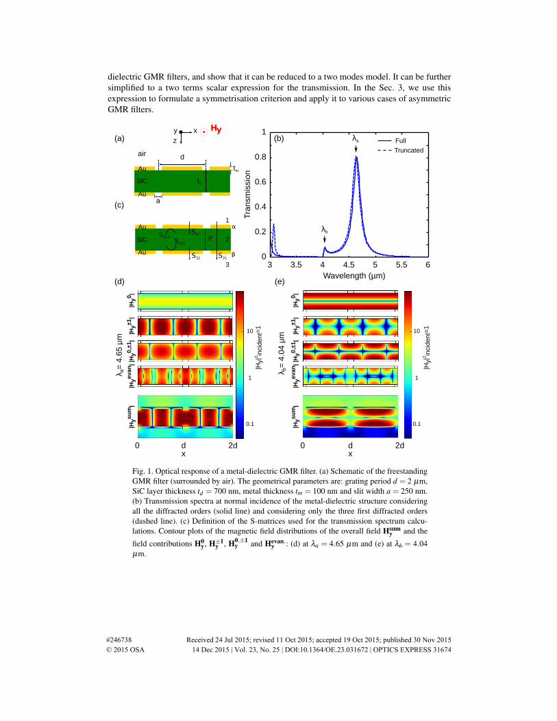
Fig. 1. Optical response of a metal-dielectric GMR filter. (a) Schematic of the freestandingGMR filter (surrounded by air). The geometrical parameters are: grating period d = 2 µm,SiC layer thickness td = 700 nm, metal thickness tm = 100 nm and slit width a = 250 nm.(b) Transmission spectra at normal incidence of the metal-dielectric structure consideringall the diffracted orders (solid line) and considering only the three first diffracted orders(dashed line). (c) Definition of the S-matrices used for the transmission spectrum calcu-lations. Contour plots of the magnetic field distributions of the overall field Hsum
y and the
field contributions H0y, H±1
y , H0,±1y and Hevan.
y : (d) at λa = 4.65 µm and (e) at λb = 4.04µm.
#246738 Received 24 Jul 2015; revised 11 Oct 2015; accepted 19 Oct 2015; published 30 Nov 2015 © 2015 OSA 14 Dec 2015 | Vol. 23, No. 25 | DOI:10.1364/OE.23.031672 | OPTICS EXPRESS 31674

2. Matrix formalism
GMRs are based on the coupling of the incident light to a waveguide via diffracted orderscreated by a periodic grating [15, 16]. In particular ref. [11] shows that the GMR is due to thecoupling of the±1st orders diffracted by a metallic grating to the dielectric layer guided-modes.The metal-dielectric GMR structure we consider consists in two identical one-dimensional goldgratings with a silicon carbide (SiC) layer in-between, as depicted on Fig. 1(a). The choice ofthe geometrical parameters stems from the procedure that was used in refs. [11] and [13] toobtain a transmission peak at 4.65µm. With the following values (grating period d = 2 µm,SiC layer thickness td = 700 nm, metal thickness tm = 100 nm and slit width a = 250 nm),we expect a high internal reflectivity of the metallic interfaces for TM-polarized light (with themagnetic field Hy parallel to the slits) [17,18], and no diffracted order in the 3 to 6 µm spectralrange. The thickness td is large enough to prevent any coupling of the evanescent waves fromthe two sides, including when the surface plasmon-polaritons are excited at wavelength closeto dnd ≈ 5.7µm, where nd the refractive index of the waveguide (2.84 for SiC).
2.1. Resonance analysis
A first transmission spectrum is calculated with the Rigorous Maxwell Constitutive Approxima-tion (RMCA) method [19] considering all the diffracted orders using N mesh points (N ≈ 100),a SiC permittivity fixed at εd = 2.842 and a dielectric function of gold given by a Drudemodel : εm(λ ) = 1− [(λp/λ + iγ)λp/λ ]−1 with λp = 159 nm and γ = 0.0048 [20, 21]. Thefull-calculation spectrum on Fig. 1(b) exhibits two transmission peaks at λa = 4.65 µm andλb = 4.04 µm. The resonance ”b” has a very low intensity compared to the resonance ”a” witha transmission up to 80%.
A second transmission spectrum is calculated by considering a smaller number of diffractedorders m, therefore the size of the S-matrices depicted on Fig. 1(c) is reduced. By using thescattering matrix formalism, the transmission amplitude S matrix of the all structure is written
S31 = S32P1/2(∞
∑k=0
(P1/2S212PS232P1/2)k)P1/2S21, (1)
or assuming that the geometrical serie converges
S31 = S32P1/2(I−P1/2S212PS232P1/2)−1P1/2S21, (2)
with I being the m×m identity matrix. The matrices S32 and S21 describe the transmission ofthe diffracted orders through the metallic gratings. The order 0 is the only one considered inthis calculation, as the only order propagating in the incoming medium 1 and the outcomingmedium 3. Thus, the matrice S32 is indeed a 1×m row vector, and the matrice S21 a m× 1column vector. The matrices S232 and S212 are m×m square matrices describing the internalscattering of the orders propagating in the medium 2 and reflecting onto the metallic mirrors.
P = (pi j) is diagonal with its components p j j = eik( j)z td and 1≤ j ≤ m; for example k(0)z , k(1)z et
k(2)z are the propagation constants of the orders 0, +1 and −1. Finally, the transmission for theall structure is T = |S31|2.
From now on, we consider the case of normal incidence, for which orders +1 and -1 areexcited symmetrically. The truncated response considering only the orders 0, +1 and -1 cor-responds to a 2× 2 matrix (m = 2), and is plotted (dotted line) on Fig. 1(b). It shows a verygood agreement with the full calculation. In this approximation, S21 and S32 are considered ascolumn and row vectors with two components, and P, S232 and S212 are 2×2 matrices.
On Fig. 1(b), the very good agreement between the exact response and the two-mode modelspectrum on the 3.5− 6 µm wavelength range demonstrates that only the propagating orders
#246738 Received 24 Jul 2015; revised 11 Oct 2015; accepted 19 Oct 2015; published 30 Nov 2015 © 2015 OSA 14 Dec 2015 | Vol. 23, No. 25 | DOI:10.1364/OE.23.031672 | OPTICS EXPRESS 31675

play a significant role in the optical response, while evanescent orders have a low influence. Infact, since only the three orders 0, +1 and −1 are propagating, all the propagation factors forj ≥ 3 tend to 0. Accordingly, the discrepancy below 3.5 µm between the resonance peaks canbe corrected by taking the ±2nd diffracted orders into account in our simplified model. Figures1(d) and 1(e) represent the magnetic field distribution over the GMR structure at λa and λb.The overall magnetic field Hsum
y is compared to the magnetic field contributions H0y, H±1
y andHevan.
y of the 0th order, the ±1st order and the evanescent orders. We also plot the magneticfield contribution H0,±1
y which corresponds to the interference between the 0th and ±1st orders(H0,±1
y is given by the cross-coupling term appearing when developing the sum |H0y+H±1
y |). Atλb, the prevalence of the 0th order is due to the Fabry-Perot resonance and therefore explains theintensity distribution of Hsum
y : the x−invariant H0y field is slightly perturbed by the d-periodic
H±1y field. At λa, the±1st diffracted orders dominate. This is consistent with the observation of
a d/2-periodic field H±1y of the standing-wave resulting from the interference of the d-periodic
orders +1 and −1. Nonetheless, for the resonance ”a” we observe that evanescent orders arequite intense. We can still neglect them because we do not consider their propagation in the SiClayer but take them into account inside the transmission and reflection matrix coefficients. Thismight yet explain the small difference we see between the two spectra on Fig. 1(a).
2.2. Scalar expression for the transmission
The loop matrix M = P1/2S212PS232P1/2 is introduced. It refers to all the multiple reflectionsonto the metallic gratings and the propagation inside the SiC layer of the 0th and±1st diffracted
orders. Diagonalizing M allows to write M = ΠDΠ−1 with D =
(da 00 db
)(Π is a transfer
matrix). Finally the Eq, (2) is equivalent to
S31 = S32P1/2Π(I−D)−1
Π−1P1/2S21. (3)
Then setting down Π =
(Π0a Π0bΠ1a Π1b
), Π−1 =
(Πa0 Πa1Πb0 Πb1
), S32 =
(sβ
0 sβ
1
), S21 =
(sα
0sα
1
)and P1/2 =
(p1/2
0 00 p1/2
1
)(with p0 = eik(0)z td , p1 = eik(±1)
z td ) and developing the Eq. (3), we
obtain a scalar expression for the transmission amplitude
S31 = (Π0a p1/20 sβ
0 +Π1a p1/21 sβ
1 )1
1−da(Πa0 p1/2
0 sα0 +Πa1 p1/2
1 sα1 )
+(Π0b p1/20 sβ
0 +Π1b p1/21 sβ
1 )1
1−db(Πb0 p1/2
0 sα0 +Πb1 p1/2
1 sα1 )
(4)
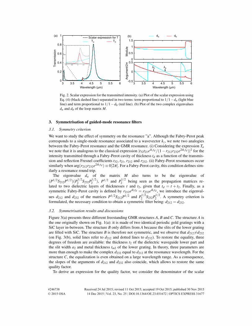
Figure 2(a) shows that the transmission spectrum can be divided in two parts in agreement withthe two-term scalar expression found for the transmission intensity
T = |S31|2 ≈ Ta +Tb, (5)
where Ta = |(Π0a p1/20 sβ
0 + Π1a p1/21 sβ
1 )(Πa0 p1/20 sα
0 + Πa1 p1/21 sα
1 )/(1 − da)|2 and Tb =
|(Π0b p1/20 sβ
0 +Π1b p1/21 sβ
1 )(Πb0 p1/20 sα
0 +Πb1 p1/21 sα
1 )/(1− db)|2. Ta approximates well the in-tensity spectrum around λa and Tb around λb. We also notice that the transmission peaks appearat λa when arg(da) ≡ 0[2π] and at λb when arg(db) ≡ 0[2π] (cf Fig. 2(b)). Therefore the 0th
and ±1st orders can be viewed as coupled resonators that interfere constructively in the GMRstructure when arg(da)≡ 0[2π] or arg(db)≡ 0[2π].
#246738 Received 24 Jul 2015; revised 11 Oct 2015; accepted 19 Oct 2015; published 30 Nov 2015 © 2015 OSA 14 Dec 2015 | Vol. 23, No. 25 | DOI:10.1364/OE.23.031672 | OPTICS EXPRESS 31676
3 3.5 4 4.5 5 5.5 6-0.5
0
0.50
0.5
1
1.5
Mod
ule
Arg
um
ent/2π
Wavelength (µm)
Tra
nsm
issi
on
Wavelength (µm)
λaλb
3 3.5 4 4.5 5 5.5 60
0.2
0.4
0.6
0.8
1Scalar expression for T
TbTa
da(b) db(a)
3.8 3.9 4 4.1 4.20
0.05
0.1
Fig. 2. Scalar expression for the transmitted intensity. (a) Plot of the scalar expression usingEq. (4) (black dashed line) separated in two terms: term proportional to 1/1−da (light blueline) and term proportional to 1/1−db (red line). (b) Plot of the two complex eigenvaluesda and db of the loop matrix M.
3. Symmetrisation of guided-mode resonance filters
3.1. Symmetry criterion
We want to study the effect of symmetry on the resonance ”a”. Although the Fabry-Perot peakcorresponds to a single-mode resonance associated to a wavevector kz, we note two analogiesbetween the Fabry-Perot resonance and the GMR resonance. (i) Considering the expression Tawe note that it is analogous to the classical expression |t32t21eikztd/(1− r212r232e2ikztd )|2 for theintensity transmitted through a Fabry-Perot cavity of thickness td as a function of the transmis-sion and reflection Fresnel coefficients t32, t21, r212 and r232. (ii) Fabry-Perot resonances occursimilarly when arg(r212r232e2ikztd )≡ 0[2π]. For a Fabry-Perot cavity, this condition defines sim-ilarly a resonance round trip.
The eigenvalue da of the matrix M also turns to be the eigenvalue of(P1/2S212P1/2)(P1/2
2 S232P1/22 ), P1/2 and P1/2
2 being seen as the propagation matrices re-lated to two dielectric layers of thicknesses t and t2, given that td = t + t2. Finally, as asymmetric Fabry-Perot cavity is defined by r212eikztd = r232eikztd , we introduce the eigenval-ues d212 and d232 of the matrices P1/2S212P1/2 and P1/2
2 S232P1/22 . A symmetry criterion is
formulated, the necessary condition to obtain a symmetric filter being: d212 = d232.
3.2. Symmetrisation results and discussions
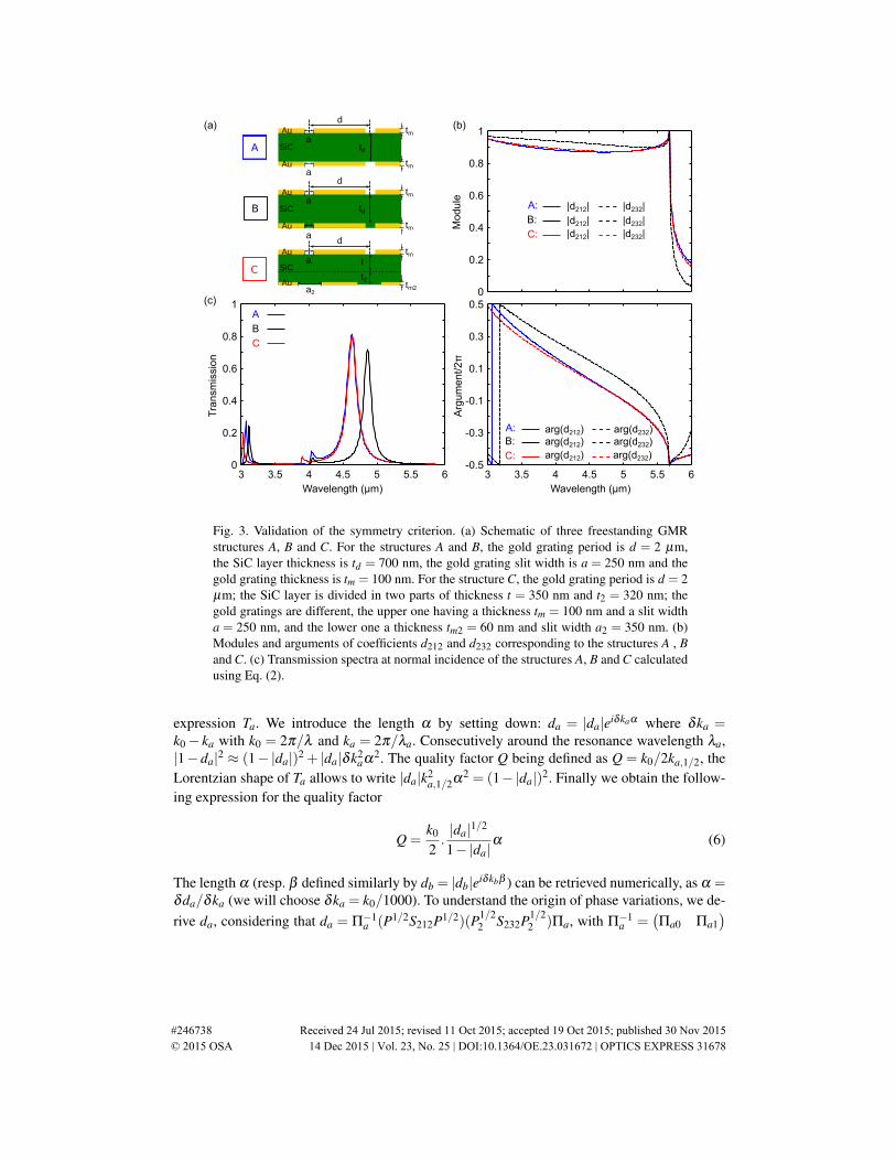
Figure 3(a) presents three different freestanding GMR structures A, B and C. The structure A isthe one originally shown on Fig. 1(a): it is made of two identical periodic gold gratings with aSiC layer in-between. The structure B only differs from A because the slits of the lower gratingare filled with SiC. The structure B is therefore not symmetric, and we observe that d212 6=d232(on Fig. 3(b), solid lines refer to d212 and dotted lines to d232). To restore the equality, threedegrees of freedom are available: the thickness t2 of the dielectric waveguide lower part andthe slit width a2 and metal thickness tm2 of the lower grating. In theory, three parameters aremore than enough to make the complex d232 equal to d212 at the resonance wavelength. For thestructure C, the equalization is even obtained on a large wavelength range. As a consequence,the slopes of the arguments of d212 and d232 also coincide, which allows to restore the samequality factor.
To derive an expression for the quality factor, we consider the denominator of the scalar
#246738 Received 24 Jul 2015; revised 11 Oct 2015; accepted 19 Oct 2015; published 30 Nov 2015 © 2015 OSA 14 Dec 2015 | Vol. 23, No. 25 | DOI:10.1364/OE.23.031672 | OPTICS EXPRESS 31677
td
d
td
d
a
tm
a
tm
tm
tm
a
a
(a)
Wavelength (µm)
Arg
um
ent/2π
Wavelength (µm)
Tra
nsm
issi
on
3 3.5 4 4.5 5 5.5 60
0.2
0.4
0.6
0.8
1
3 3.5 4 4.5 5 5.5 6-0.5
-0.3
-0.1
0.1
0.3
0.5
Mod
ule
0
0.2
0.4
0.6
0.8
1
A:B:
C:
arg(d232)arg(d212)arg(d212)arg(d212)
arg(d232)arg(d232)
(c)
(b)
t
d
a2
tm
tm2
a
A
C
B
A
B
C
A:
B:
C:
|d212||d212||d212|
|d232||d232||d232|
Au
Au
SiC
Au
Au
SiC
Au
Au
SiCt2
Fig. 3. Validation of the symmetry criterion. (a) Schematic of three freestanding GMRstructures A, B and C. For the structures A and B, the gold grating period is d = 2 µm,the SiC layer thickness is td = 700 nm, the gold grating slit width is a = 250 nm and thegold grating thickness is tm = 100 nm. For the structure C, the gold grating period is d = 2µm; the SiC layer is divided in two parts of thickness t = 350 nm and t2 = 320 nm; thegold gratings are different, the upper one having a thickness tm = 100 nm and a slit widtha = 250 nm, and the lower one a thickness tm2 = 60 nm and slit width a2 = 350 nm. (b)Modules and arguments of coefficients d212 and d232 corresponding to the structures A , Band C. (c) Transmission spectra at normal incidence of the structures A, B and C calculatedusing Eq. (2).
expression Ta. We introduce the length α by setting down: da = |da|eiδkaα where δka =k0− ka with k0 = 2π/λ and ka = 2π/λa. Consecutively around the resonance wavelength λa,|1−da|2 ≈ (1−|da|)2 + |da|δk2
aα2. The quality factor Q being defined as Q = k0/2ka,1/2, theLorentzian shape of Ta allows to write |da|k2
a,1/2α2 = (1−|da|)2. Finally we obtain the follow-ing expression for the quality factor
Q =k0
2.|da|1/2
1−|da|α (6)
The length α (resp. β defined similarly by db = |db|eiδkbβ ) can be retrieved numerically, as α =δda/δka (we will choose δka = k0/1000). To understand the origin of phase variations, we de-rive da, considering that da = Π−1
a (P1/2S212P1/2)(P1/22 S232P1/2
2 )Πa, with Π−1a =
(Πa0 Πa1
)
#246738 Received 24 Jul 2015; revised 11 Oct 2015; accepted 19 Oct 2015; published 30 Nov 2015 © 2015 OSA 14 Dec 2015 | Vol. 23, No. 25 | DOI:10.1364/OE.23.031672 | OPTICS EXPRESS 31678
and Πa =
(Π0aΠ1a
), and we obtain the first order differential
δda = (δΠ−1a )P1/2S212P1/2P1/2
2 S232P1/22 Πa
+Π−1a (δP1/2)S212P1/2P1/2
2 S232P1/22 Πa
+Π−1a P1/2(δS212)P1/2P1/2
2 S232P1/22 Πa
+Π−1a P1/2S212(δP1/2)P1/2
2 S232P1/22 Πa
+Π−1a P1/2S212P1/2(δP1/2
2 )S232P1/22 Πa
+Π−1a P1/2S212P1/2P1/2
2 (δS232)P1/22 Πa
+Π−1a P1/2S212P1/2P1/2
2 S232(δP′1/2)Πa
+Π−1a P1/2S212P1/2P1/2
2 S232P1/22 (δΠa)
+o(δda).
(7)
These 8 terms have been evaluated numerically. It appears that, contrary to the case of asimple Fabry-Perot filter where the phase variations at reflection onto the mirrors are negligi-ble, the terms Π−1
a P1/2(δS212)P1/2P1/22 S232P1/2
2 Πa and Π−1a P1/2S212P1/2P1/2
2 (δS232)P1/22 Πa
must be taken into account. Furthermore, we notice that the first and last terms of this sum(δΠ−1
a )P1/2S212P1/2P1/22 S232P1/2
2 Πa and Π−1a P1/2S212P1/2P1/2
2 S232P1/22 (δΠa) are negligible.
Wavelength (µm)3 3.5 4 4.5 5 5.5 6
0
1
2
3
|det
|
det(I-M)
(1-|da|eiδkaα)(1-|db|e
iδkbβ)
λaλb
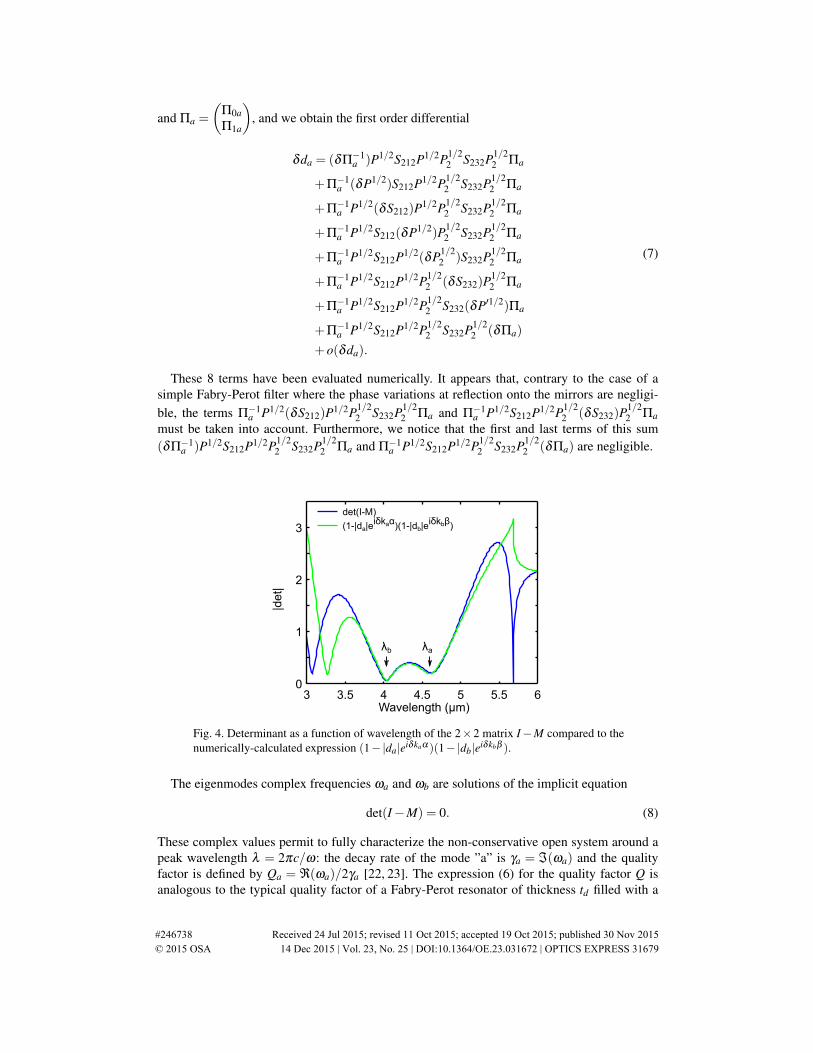
Fig. 4. Determinant as a function of wavelength of the 2×2 matrix I−M compared to thenumerically-calculated expression (1−|da|eiδkaα )(1−|db|eiδkbβ ).
The eigenmodes complex frequencies ωa and ωb are solutions of the implicit equation
det(I−M) = 0. (8)
These complex values permit to fully characterize the non-conservative open system around apeak wavelength λ = 2πc/ω: the decay rate of the mode ”a” is γa = ℑ(ωa) and the qualityfactor is defined by Qa = ℜ(ωa)/2γa [22, 23]. The expression (6) for the quality factor Q isanalogous to the typical quality factor of a Fabry-Perot resonator of thickness td filled with a
#246738 Received 24 Jul 2015; revised 11 Oct 2015; accepted 19 Oct 2015; published 30 Nov 2015 © 2015 OSA 14 Dec 2015 | Vol. 23, No. 25 | DOI:10.1364/OE.23.031672 | OPTICS EXPRESS 31679

(b)(a)
td
d
a
tm
tm
aA
Au
Au
SiC
td
d
a
tm
tm
a
B'
Au
Au
SiC
td/2
d
a2
tm
tm2
aC'
Au
Au
SiCt'd/2
sapphire
sapphire
Mod
ule
0
0.2
0.4
0.6
0.8
1
A:
B':
C':
|d212||d212||d212|
|d232||d232||d232|
Wavelength (µm)
Tra
nsm
issi
on
3 3.5 4 4.5 5 5.5 60
0.2
0.4
0.6
0.8
1
Wavelength (µm)
Arg
um
ent/2π
A
B'
C'
3 3.5 4 4.5 5 5.5 6-0.5
-0.3
-0.1
0.1
0.3
0.5
A:
B':
C':
(c)
Fig. 5. Symmetrisation of GMR filters on a sapphire substrate of refractive 1.7. (a)Schematic of three GMR structures A, B′ and C′. The structure B′ has the same geometricalparameters than the structure B. For the structure C′, the gold grating period is d = 2 µm;the SiC layer is divided in two parts of thickness t = 350 nm and t2 = 230 nm; the gold grat-ings are different, the upper one having a thickness tm = 100 nm and a slit width a = 250nm, and the lower one a thickness tm2 = 50 nm and slit width a2 = 290 nm. (b) Modulesand arguments of coefficients d212 and d232 corresponding to the structures A , B′ and C′.(c) Transmission spectra at normal incidence of the structures A, B′ and C′ calculated usingequation (2).
dielectric of refractive index nd [24]:
Q =k0
2.|r|1/2
1−|r|(2ndtd), (9)
given that r = r212r232 for highly reflecting interfaces. α is therefore similar to 2ndtd , and cantherefore be considered as the cavity optical length.
The assumption that the system is separated in two independent resonators (indexed as a andb) is confirmed by Fig. 4, which shows the exact value of det(I−M) and the approximated valueobtained as the product of terms (1−da) and (1−db). The two curves are in good agreementover a wide spectral range around the resonance peaks λa and λb.
Figure 5 shows the result of the symmetrisation approach for a GMR filter on a sapphire sub-strate. We manage to make d212 equal to d232 at the resonance wavelength λa. This allows to ob-tain the same transmission maxima for the original freestanding structure A and the structure onsubstrate C′, but not the same quality factor (on Fig. 5 (c) the transmission peak of the structure
#246738 Received 24 Jul 2015; revised 11 Oct 2015; accepted 19 Oct 2015; published 30 Nov 2015 © 2015 OSA 14 Dec 2015 | Vol. 23, No. 25 | DOI:10.1364/OE.23.031672 | OPTICS EXPRESS 31680

C′ appears larger than the one related to the original structure A). The equalization is obtainedby enlarging the slits and reducing the thickness of the lower grating. Under these conditions,
the hypothesis of a highly reflecting interface and the approximation− 1ln|r| ≈
|r|1/2
1−|r| at first ordermay no longer be valid, especially as the index contrast between the dielectric waveguide andthe sapphire substrate is low. Therefore, second order terms should be considered. Finally, thisexplains why the the quality factor is not restored in addition to the transmission maximumvalue at the original resonance wavelength λa, even though the symmetry criterion is fulfilled:in this case, the influence of second order terms would require in addition to suppress the smalldiscrepancy we observe on Fig. 5(b) between the slopes of the coefficients d212 and d232 (bothfor the modules and arguments), responsible for the slightly lower quality factor we observedfor the structure C′.
4. Conclusion
We have proposed a mathematical framework to study the symmetry of metal-dielectric GMRfilters. The analysis of the GMR resonance mechanism shows that only the 0th and ±1st
diffracted orders play a significant role. As a consequence, we can reduce the size of the scat-tering matrices involved in the RMCA method computation. This reduction allows to write ascalar expression for the intensity transmitted through the GMR structures. A symmetry cri-terion is then formulated by noticing strong analogies between this expression and the onefor standard Fabry-Perot filters. Satisfying this symmetry criterion by adapting the geometri-cal parameters at the resonance wavelength allows to restore the same transmission maximumvalue and quality factor than the original symmetric freestanding structure, at the same originalresonance wavelength.
This simplification could also be applied to design GMR filters with a large angular ac-ceptance [13], GMR filters exhibiting perfect extinction [25] or for example resonators to beintegrated in VCSELs [26, 27], providing the minimum number of electromagnetic modes de-scribing the system is small.
#246738 Received 24 Jul 2015; revised 11 Oct 2015; accepted 19 Oct 2015; published 30 Nov 2015 © 2015 OSA 14 Dec 2015 | Vol. 23, No. 25 | DOI:10.1364/OE.23.031672 | OPTICS EXPRESS 31681