two port frequency reconfigurable antenna for cognitive radios
TRANSCRIPT
Two port frequency reconfigurable antennafor cognitive radios
F. Ghanem, P.S. Hall and J.R. Kelly
A two port frequency reconfigurable antenna for cognitive radios ispresented. It is composed of a disc monopole with two ports thatexcite at opposite sides; one port is very wideband and consists of acoplanar feed line and the other port is tunable narrowband and consistsof a microstrip feed line with defect slots in its ground plane. The slotsact as a filter that suppresses frequencies outside the desired band, itsoperating frequency band can be tuned by varying the length of theslots. The two ports are decoupled by at least 10 dB through theconsidered frequency range. It is believed that the proposed antennacan be a good candidate for cognitive radios in generic small basestations where the narrowband port is used for operation and the wide-band one is used for sensing the spectrum. For accuracy, it is importantthat the sensing (measurement of the interference noise) is made withthe same polarisation as the operation and the proposed antennaachieves this by having the two collinear ports. To examine the pre-sented approach, simulated and measured results are presented andgood agreement is reported.
Introduction: With the advances realised in the wireless communi-cations domain, the number of users is increasing rapidly, which willlead to the saturation of important parts of the spectrum. In addition,it has been shown that a large portion of the spectrum is not adequatelyused [1]. One of the solutions to the spectrum saturation problemconsists of the cognitive radio (CR) concept, where the radios havethe capability of learning and adapting to the environment where theyoperate. One of these adaptations involves changing the operatingfrequency [2–4]. In the future, it is suggested that the spectrum willbe deregulated and cognitive radios could operate in any frequencyband within the available spectrum. To this end, CRs must sense thespectrum to find a suitable frequency band to operate in, and then useit to transmit and receive data. While there is no agreed scheme forthe operation and the sensing modes in cognitive radios yet, one possi-bility involves having an antenna with its front-end used for continuoussensing and another antenna with its front-end for the operation. Tomake sensing of the whole spectrum quick, it is suggested that thesensing antenna could be very wideband and the front-end wouldperform the frequency subdivision, scanning and filtering to achieve aconvenient noise level for measuring the interference. It is alsosuggested that the operation antenna should be narrowband to helpfilter out-of-band signals [5].
In this Letter, we present a new two port antenna that integrates thetwo antennas needed for CRs in the same space. It consists of a discmonopole with two ports disposed at opposite sides; one port consistsof a coplanar feed line that gives very wideband operation and theother port is a microstrip feed line with defect slots in its groundplane. The slots act as a filter and are designed to suppress frequenciesoutside the desired band; the operating frequency band can be tuned byvarying the length of the slots. To ensure that the sensing is measuringinterference at the same polarisation as the operation, the two antennaports must be collinear. The other advantage of having the two portsat opposite sides is the low mutual coupling it gives since the twoports are decoupled by at least 10 dB through the whole of theconsidered range.
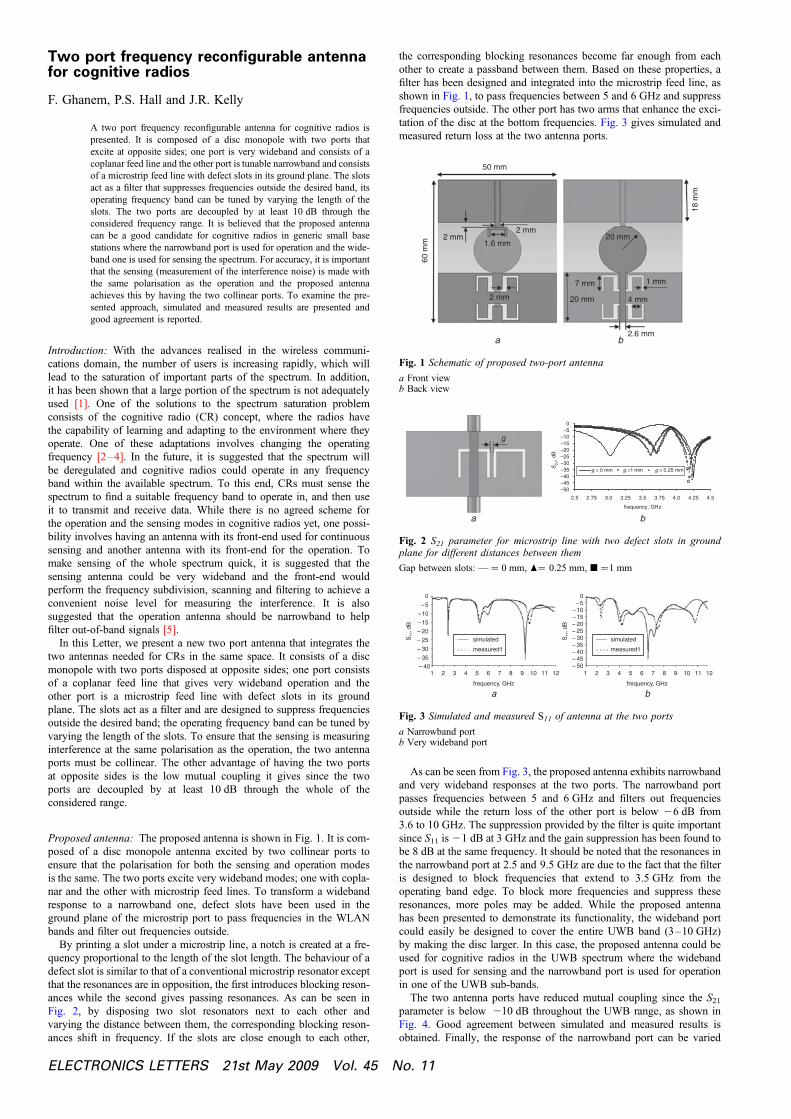
Proposed antenna: The proposed antenna is shown in Fig. 1. It is com-posed of a disc monopole antenna excited by two collinear ports toensure that the polarisation for both the sensing and operation modesis the same. The two ports excite very wideband modes; one with copla-nar and the other with microstrip feed lines. To transform a widebandresponse to a narrowband one, defect slots have been used in theground plane of the microstrip port to pass frequencies in the WLANbands and filter out frequencies outside.
By printing a slot under a microstrip line, a notch is created at a fre-quency proportional to the length of the slot length. The behaviour of adefect slot is similar to that of a conventional microstrip resonator exceptthat the resonances are in opposition, the first introduces blocking reson-ances while the second gives passing resonances. As can be seen inFig. 2, by disposing two slot resonators next to each other andvarying the distance between them, the corresponding blocking reson-ances shift in frequency. If the slots are close enough to each other,
ELECTRONICS LETTERS 21st May 2009 Vol. 45 N
the corresponding blocking resonances become far enough from eachother to create a passband between them. Based on these properties, afilter has been designed and integrated into the microstrip feed line, asshown in Fig. 1, to pass frequencies between 5 and 6 GHz and suppressfrequencies outside. The other port has two arms that enhance the exci-tation of the disc at the bottom frequencies. Fig. 3 gives simulated andmeasured return loss at the two antenna ports.
50 mm
2 mm 2 mm
2 mm 20 mm
20 mm
7 mm 1 mm
4 mm
2.6 mm
18 m
m
60 m
m
1.6 mm
a b
Fig. 1 Schematic of proposed two-port antenna
a Front viewb Back view
–50 –45 –40 –35 –30 –25 –20 –15 –10 –5 0
g
2.5 2.75 3.0 3.25 3.5 3.75 4.0 4.25 4.5
frequency, GHz
ba
S21
, dB
g = 0 mm g =1 mm g = 0.25 mm
Fig. 2 S21 parameter for microstrip line with two defect slots in groundplane for different distances between them
Gap between slots: — ¼ 0 mm, O¼ 0.25 mm, B ¼1 mm
1 2 3 4 5 6 7
frequency, GHz
a b
8 9 10 11 12 1 2 3 4 5 6 7
frequency, GHz
8 9 10 11 12
0 –5
–10 –15 – 20 – 25 – 30 – 35 – 40 – 45 – 50
S11
, dB
0
–5
–10
–15
– 20
– 25
– 30
– 35
– 40
S11
, dB
simulated
measured1
simulated
measured1
Fig. 3 Simulated and measured S11 of antenna at the two ports
a Narrowband portb Very wideband port
As can be seen from Fig. 3, the proposed antenna exhibits narrowbandand very wideband responses at the two ports. The narrowband portpasses frequencies between 5 and 6 GHz and filters out frequenciesoutside while the return loss of the other port is below 26 dB from3.6 to 10 GHz. The suppression provided by the filter is quite importantsince S11 is 21 dB at 3 GHz and the gain suppression has been found tobe 8 dB at the same frequency. It should be noted that the resonances inthe narrowband port at 2.5 and 9.5 GHz are due to the fact that the filteris designed to block frequencies that extend to 3.5 GHz from theoperating band edge. To block more frequencies and suppress theseresonances, more poles may be added. While the proposed antennahas been presented to demonstrate its functionality, the wideband portcould easily be designed to cover the entire UWB band (3–10 GHz)by making the disc larger. In this case, the proposed antenna could beused for cognitive radios in the UWB spectrum where the widebandport is used for sensing and the narrowband port is used for operationin one of the UWB sub-bands.
The two antenna ports have reduced mutual coupling since the S21
parameter is below 210 dB throughout the UWB range, as shown inFig. 4. Good agreement between simulated and measured results isobtained. Finally, the response of the narrowband port can be varied
o. 11

by modifying the slot length. Fig. 5 gives the antenna response of theredesigned narrowband port in the band 4–5 GHz.
0
–5
–10
–15
–20
–25
–30
–35
–40
S21
, dB
frequency, GHz1 2 3 4 5 6 7 8 9 10 11 12
simulated measured
Fig. 4 Simulated and measured S21 between the two ports of proposedantenna
0
–5
–10
–15
S11
, dB
–20
–25
–30
–352 3 4 5 6 7
frequency, GHz
Fig. 5 Simulated S11 of narrowband port at frequency band 4–5 GHz
It should be noted that to prevent the transmitted power from the oper-ating port being fed to the sensing front-end, RF switches must be addedafter the wideband port in order to avoid saturation and burning of thesensing front-end.
ELECTRO
Conclusion: A new two port antenna has been presented for cognitiveradios. It is composed of a disc monopole with two ports that excite atunable narrowband mode and a very wideband mode, respectively.Simulated and measured results have shown good agreement, whichmakes the proposed antenna a good candidate for CRs where the twoports are used for the sensing of the spectrum and operation.
# The Institution of Engineering and Technology 20093 April 2009doi: 10.1049/el.2009.0935
F. Ghanem, P.S. Hall and J.R. Kelly (Department of Electronic,Electrical and Computer Engineering, School of Engineering,University of Birmingham, Edgbaston, Birmingham B15 2TT, UnitedKingdom)
E-mail: [email protected]
References
1 Cabric, D., Mishra, S.M., and Brodersen, R.W.: ‘Implementationissues in spectrum sensing for cognitive radios’. Proc. Asilomar Conf.on Signals, Systems, and Computers, Pacific Grove, CA, USA,November 2004, Vol. 1, pp. 772–776
2 Gardner, P., Hamid, M.R., Hall, P.S., Kelly, J., Ghanem, F., andEbrahimi, E.: ‘Reconfigurable antennas for cognitive radio:requirements and potential design’. IET seminar on wideband,multiband, antennas and arrays for civil or defence applications, March2008, London, UK
3 Malik, Q.M., and Edwards, D.J.: ‘Cognitive techniques for ultrawideband communications’. IET seminar on ultra wideband systems,technologies and applications, London, UK, April 2006
4 Cabric, D., Mishra, S.M., Willkomm, D., Brodersen, R., and Wolisz, A.:‘A Cognitive radio approach for usage of virtual unlicensed spectrum’.14th IST Mobile Wireless Communications Summit, Dresden,Germany, June 2005
5 Aberle, J., et al.: ‘Automatically tuning antenna for software-defined andcognitive radio,’ Proc. Software Defined Radio Technical Conf., OrangeCounty, CA, USA, November 2005
NICS LETTERS 21st May 2009 Vol. 45 No. 11