tx 700 800
TRANSCRIPT

8/22/2019 TX 700 800
http://slidepdf.com/reader/full/tx-700-800 1/234
EPSON Artisan 800/ Stylus Photo PX800FW/ Stylus Photo TX800FW/ Artisan 700/ Stylus Photo PX700FW/ Stylus Photo TX700FW
Color Inkjet Printer
SEMF08-004
SERVICE M NU L
Confidential
8/22/2019 TX 700 800
http://slidepdf.com/reader/full/tx-700-800 2/234
Confidential
Notice: All rights reserved. No part of this manual may be reproduced, stored in a retrieval system, or transmitted in any form or by any means, electronic, mechanical,
photocopying, recording, or otherwise, without the prior written permission of SEIKO EPSON CORPORATION.
The contents of this manual are subject to change without notice.
All effort have been made to ensure the accuracy of the contents of this manual. However, should any errors be detected, SEIKO EPSON would greatly appreciate being
informed of them.
The above not withstanding SEIKO EPSON CORPORATION can assume no responsibility for any errors in this manual or the consequences thereof.
EPSON is a registered trademark of SEIKO EPSON CORPORATION.
General Notice: Other product names used herein are for identification purpose only and may be trademarks or registered trademarks of their
respective owners. EPSON disclaims any and all rights in those marks.
Copyright © 2008 SEIKO EPSON CORPORATION.
Imaging Products CS, PL & Environmental Management
8/22/2019 TX 700 800
http://slidepdf.com/reader/full/tx-700-800 3/234
Confidential
PRECAUTIONS
Precautionary notations throughout the text are categorized relative to 1) Personal injury and 2) damage to equipment.
DANGER Signals a precaution which, if ignored, could result in serious or fatal personal injury. Great caution should be exercised in performing procedures preceded by
DANGER Headings.
WARNING Signals a precaution which, if ignored, could result in damage to equipment.
The precautionary measures itemized below should always be observed when performing repair/maintenance procedures.
DANGER
1. ALWAYS DISCONNECT THE PRODUCT FROM THE POWER SOURCE AND PERIPHERAL DEVICES PERFORMING ANY MAINTENANCE OR REPAIR
PROCEDURES.
2. NO WORK SHOULD BE PERFORMED ON THE UNIT BY PERSONS UNFAMILIAR WITH BASIC SAFETY MEASURES AS DICTATED FOR ALL ELECTRONICS
TECHNICIANS IN THEIR LINE OF WORK.
3. WHEN PERFORMING TESTING AS DICTATED WITHIN THIS MANUAL, DO NOT CONNECT THE UNIT TO A POWER SOURCE UNTIL INSTRUCTED TO DO
SO. WHEN THE POWER SUPPLY CABLE MUST BE CONNECTED, USE EXTREME CAUTION IN WORKING ON POWER SUPPLY AND OTHER ELECTRONIC
COMPONENTS.
4. WHEN DISASSEMBLING OR ASSEMBLING A PRODUCT, MAKE SURE TO WEAR GLOVES TO AVOID INJURIER FROM METAL PARTS WITH SHARP EDGES.
WARNING
1. REPAIRS ON EPSON PRODUCT SHOULD BE PERFORMED ONLY BY AN EPSON CERTIFIED REPAIR TECHNICIAN.
2. MAKE CERTAIN THAT THE SOURCE VOLTAGES IS THE SAME AS THE RATED VOLTAGE, LISTED ON THE SERIAL NUMBER/RATING PLATE. IF THE
EPSON PRODUCT HAS A PRIMARY AC RATING DIFFERENT FROM AVAILABLE POWER SOURCE, DO NOT CONNECT IT TO THE POWER SOURCE.
3. ALWAYS VERIFY THAT THE EPSON PRODUCT HAS BEEN DISCONNECTED FROM THE POWER SOURCE BEFORE REMOVING OR REPLACING PRINTEDCIRCUIT BOARDS AND/OR INDIVIDUAL CHIPS.
4. IN ORDER TO PROTECT SENSITIVE MICROPROCESSORS AND CIRCUITRY, USE STATIC DISCHARGE EQUIPMENT, SUCH AS ANTI-STATIC WRIST
STRAPS, WHEN ACCESSING INTERNAL COMPONENTS.
5. REPLACE MALFUNCTIONING COMPONENTS ONLY WITH THOSE COMPONENTS BY THE MANUFACTURE; INTRODUCTION OF SECOND-SOURCE ICs OR
OTHER NON-APPROVED COMPONENTS MAY DAMAGE THE PRODUCT AND VOID ANY APPLICABLE EPSON WARRANTY.
6. WHEN USING COMPRESSED AIR PRODUCTS; SUCH AS AIR DUSTER, FOR CLEANING DURING REPAIR AND MAINTENANCE, THE USE OF SUCH
PRODUCTS CONTAINING FLAMMABLE GAS IS PROHIBITED.

8/22/2019 TX 700 800
http://slidepdf.com/reader/full/tx-700-800 4/234Confidential
About This ManualThis manual describes basic functions, theory of electrical and mechanical operations, maintenance and repair procedures of the printer. The instructions and procedures included
herein are intended for the experienced repair technicians, and attention should be given to the precautions on the preceding page.
Manual Configuration
This manual consists of six chapters and Appendix.
CHAPTER 1.PRODUCT DESCRIPTIONS
Provides a general overview and specifications of the product.CHAPTER 2.OPERATING PRINCIPLES
Describes the theory of electrical and mechanical operations of the
product.
CHAPTER 3.TROUBLESHOOTING
Describes the step-by-step procedures for the troubleshooting.
CHAPTER 4.DISASSEMBLY / ASSEMBLY
Describes the step-by-step procedures for disassembling and assembling
the product.
CHAPTER 5.ADJUSTMENT
Provides Epson-approved methods for adjustment.
CHAPTER 6.MAINTENANCE
Provides preventive maintenance procedures and the lists of Epson-
approved lubricants and adhesives required for servicing the product.
APPENDIX Provides the following additional information for reference:
• Exploded Diagram
• Parts List
Symbols Used in this Manual
Various symbols are used throughout this manual either to provide additional
information on a specific topic or to warn of possible danger present during a
procedure or an action. Be aware of all symbols when they are used, and always read NOTE, CAUTION, or WARNING messages.
Indicates an operating or maintenance procedure, practice or condition
that is necessary to keep the product’s quality.
Indicates an operating or maintenance procedure, practice, or condition
that, if not strictly observed, could result in damage to, or destruction of,equipment.
May indicate an operating or maintenance procedure, practice or
condition that is necessary to accomplish a task efficiently. It may also
provide additional information that is related to a specific subject, or
comment on the results achieved through a previous action.
Indicates an operating or maintenance procedure, practice or condition
that, if not strictly observed, could result in injury or loss of life.
Indicates that a particular task must be carried out according to a certain
standard after disassembly and before re-assembly, otherwise the
quality of the components in question may be adversely affected.

8/22/2019 TX 700 800
http://slidepdf.com/reader/full/tx-700-800 5/234Confidential
Revision Status
Revision Date of Issue Description
A August 27, 2008 First Release

8/22/2019 TX 700 800
http://slidepdf.com/reader/full/tx-700-800 6/234

8/22/2019 TX 700 800
http://slidepdf.com/reader/full/tx-700-800 7/234

8/22/2019 TX 700 800
http://slidepdf.com/reader/full/tx-700-800 8/234

8/22/2019 TX 700 800
http://slidepdf.com/reader/full/tx-700-800 9/234Confidential
C H A P T E R
1PRODUCT DESCRIPTION
8/22/2019 TX 700 800
http://slidepdf.com/reader/full/tx-700-800 10/234
EPSON Artisan 800/EPSON Stylus Photo PX800FW/TX800FW/Artisan 700/EPSON Stylus Photo PX700W/TX700W Revision A
PRODUCT DESCRIPTION Features 10
Confidential
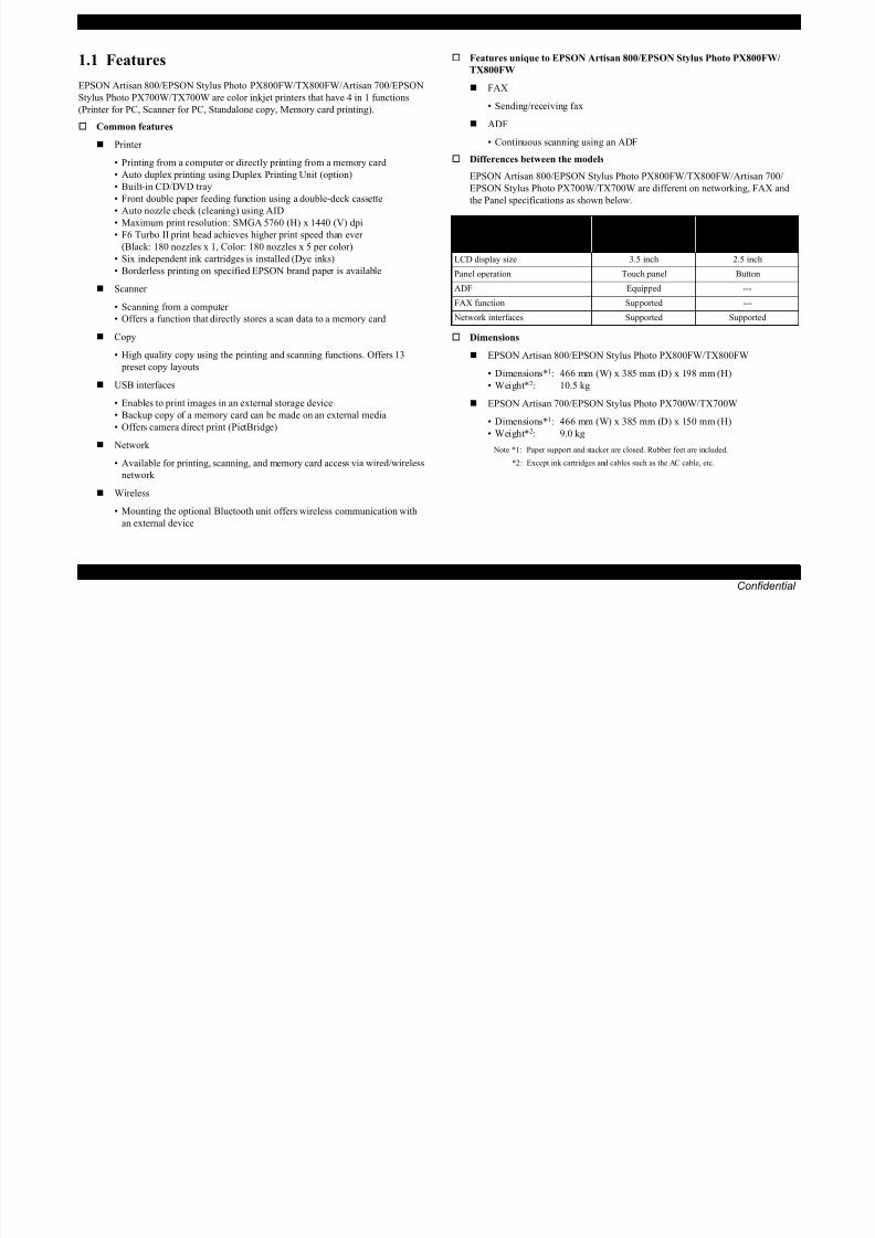
1.1 Features
EPSON Artisan 800/EPSON Stylus Photo PX800FW/TX800FW/Artisan 700/EPSON
Stylus Photo PX700W/TX700W are color inkjet printers that have 4 in 1 functions
(Printer for PC, Scanner for PC, Standalone copy, Memory card printing).
Common features
Printer
• Printing from a computer or directly printing from a memory card
• Auto duplex printing using Duplex Printing Unit (option)
• Built-in CD/DVD tray
• Front double paper feeding function using a double-deck cassette
• Auto nozzle check (cleaning) using AID• Maximum print resolution: SMGA 5760 (H) x 1440 (V) dpi
• F6 Turbo II print head achieves higher print speed than ever
(Black: 180 nozzles x 1, Color: 180 nozzles x 5 per color)
• Six independent ink cartridges is installed (Dye inks)
• Borderless printing on specified EPSON brand paper is available
Scanner
• Scanning from a computer
• Offers a function that directly stores a scan data to a memory card
Copy
• High quality copy using the printing and scanning functions. Offers 13
preset copy layouts
USB interfaces
• Enables to print images in an external storage device
• Backup copy of a memory card can be made on an external media
• Offers camera direct print (PictBridge)
Network
• Available for printing, scanning, and memory card access via wired/wireless
network
Wireless
• Mounting the optional Bluetooth unit offers wireless communication with
an external device
Features unique to EPSON Artisan 800/EPSON Stylus Photo PX800FW/
TX800FW
FAX
• Sending/receiving fax
ADF
• Continuous scanning using an ADF
Differences between the models
EPSON Artisan 800/EPSON Stylus Photo PX800FW/TX800FW/Artisan 700/
EPSON Stylus Photo PX700W/TX700W are different on networking, FAX and
the Panel specifications as shown below.
Dimensions
EPSON Artisan 800/EPSON Stylus Photo PX800FW/TX800FW
• Dimensions*1: 466 mm (W) x 385 mm (D) x 198 mm (H)
• Weight*2: 10.5 kg
EPSON Artisan 700/EPSON Stylus Photo PX700W/TX700W
• Dimensions*1: 466 mm (W) x 385 mm (D) x 150 mm (H)• Weight*2: 9.0 kg
Note *1: Paper support and stacker are closed. Rubber feet are included.
*2 : Except ink cartridges and cables such as the AC cable, etc.
Item
EPSON Artisan 800/
EPSON Stylus Photo
PX800FW/TX800FW
EPSON Artisan 700/
EPSON Stylus Photo
PX700W/TX700W
LCD display size 3.5 inch 2.5 inch
Panel operation Touch panel Button
ADF Equipped ---
FAX function Supported ---
Network interfaces Supported Supported

8/22/2019 TX 700 800
http://slidepdf.com/reader/full/tx-700-800 11/234
EPSON Artisan 800/EPSON Stylus Photo PX800FW/TX800FW/Artisan 700/EPSON Stylus Photo PX700W/TX700W Revision A
PRODUCT DESCRIPTION Printing Specifications 11
Confidential
1.2 Printing Specifications
1.2.1 Basic Specifications
1.2.2 Ink Cartridge
The product numbers of the EPSON ink cartridges for this printer are shown below.
Shelf life
Two years from production date (if unopened), six months after opening package. Storage Temperature
Dimension
12.7 mm (W) x 68 mm (D) x 47 mm (H)
Table 1-1. Printer Specifications
Item Specification
Print method On-demand ink jet
Nozzle configuration
Black: 180 nozzles x 1
Color: 180 nozzles x 5
(Light Cyan, Magenta, Yellow, Cyan, Light Magenta)
Print direction Bi-directional minimum distance printing, Unidirectional printing
Print resolution
Horizontal x Vertical (dpi)
• 360 x 180 • 720 x 720
• 360 x 360 • SMGA 5760 x 1440 (1440 x 1440)
• 720 x 360
Control code
• ESC/P Raster command
• ESC/P-R (RGB) command
• EPSON Remote command
Input buffer size 64 KbytesPaper feed method Friction feed, using the ASF (Auto Sheet Feeder)
Paper path Front feed, front out
Paper feed rates T.B.D ms (at 25.4mm feed)
PF interval Programmable in 0.01764 mm (1/1440 inch) steps
Table 1-2. Product No. of Ink Cartridges
Color EAI Latin/CISMEA/Asia Euro
Black T0981 (S)T0811N (S)
T0821N (2S)
T0791 (S)
T0801 (2S)
CyanT0982 (S)
T0992 (2S)
T0812N (S)
T0822N (2S)
T0792 (S)
T0802 (2S)
MagentaT0983 (S)
T0993 (2S)
T0813N (S)
T0823N (2S)
T0793 (S)
T0803 (2S)
Yellow T0984 (S)T0994 (2S)
T0814N (S)T0824N (2S)
T0794 (S)T0804 (2S)
Light CyanT0985 (S)
T0995 (2S)
T0815N (S)
T0825N (2S)
T0795 (S)
T0805 (2S)
Light MagentaT0986 (S)
T0996 (2S)
T0816N (S)
T0826N (2S)
T0796 (S)
T0806 (2S)
Table 1-3. Storage Temperature
Situation Storage Temperature Limit
When stored in individual boxes-20 oC to 40 oC
(-4oF to 104oF)1 month max. at 40 oC (104oF)
When installed in main unit
-20 oC to 40 oC
(-4oF to 104oF)
Do not use expired ink cartridges.
The ink in the ink cartridge freezes at -16 °C (3.2 oF). It takes
about three hours under 25 °C (77oF) until the ink thaws and
becomes usable.
8/22/2019 TX 700 800
http://slidepdf.com/reader/full/tx-700-800 12/234
EPSON Artisan 800/EPSON Stylus Photo PX800FW/TX800FW/Artisan 700/EPSON Stylus Photo PX700W/TX700W Revision A
PRODUCT DESCRIPTION Printing Specifications 12
Confidential
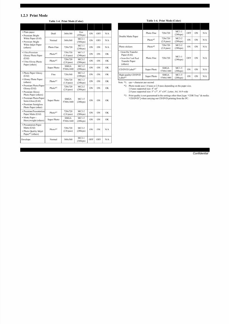
1.2.3 Print Mode
Note *1: cps = character per second*2 : Photo mode uses 1.0 pass or 2.0 pass depending on the paper size.
1.0 pass supported size: 4” x6”
2.0 pass supported size: 5” x7”, 8” x10”, Letter, A4, 16:9 wide
*3 : Print quality is not guaranteed in the settings other than [type: “CDR Tray” & media:
“CD/DVD”] when carrying out CD/DVD printing from the PC.
Table 1-4. Print Mode (Color)
Media Print ModeResolution
(H x V) dpi
Dot Size
(cps*1)Bi-d
Micro
Weave
Border-
less
• Plain paper
• Premium Bright
White Paper (EAI)
• Premium Bright
White Inkjet Paper
(others)
Draft 360x180Eco
(450cps)ON OFF N/A
Normal 360x360MC2-1
(360cps)ON OFF N/A
Photo Fine 720x720MC1-1
(240cps)ON ON N/A
• Ultra Premium
Glossy Photo Paper(EAI)
• Ultra Glossy Photo
Paper (others)
Photo*2 720x720
(1.0 pass)
MC1-2
(240cps)ON ON OK
Photo*2 720x720
(2.0 pass)
MC2-2
(280cps)ON ON OK
Super PhotoSMGA
5760x1440
MC1-5
(200cps)ON ON OK
• Photo Paper Glossy
(EAI)
• Glossy Photo Paper
(others)• Premium Photo Paper
Glossy (EAI)
• Premium Glossy
Photo Paper (others)
• Premium Photo Paper
Semi-Gloss (EAI)
• Premium Semigloss
Photo Paper (other)
Fine 720x360MC1-2
(240cps)ON ON OK
Photo*2 720x720
(1.0 pass)
MC1-2
(240cps)ON ON OK
Photo*2 720x720
(2.0 pass)
MC2-2
(280cps)ON ON OK
Super PhotoSMGA
5760x1440
MC1-5
(200cps)ON ON OK
• Premium Presentation
Paper Matte (EAI)
• Matte Paper -
Heavyweight (others)
Photo*2 720x720
(2.0 pass)
MC2-2
(280cps)ON ON OK
Super PhotoSMGA
5760x1440
MC1-5
(200cps)ON ON OK
• Presentation Paper
Matte (EAI)
• Photo Quality Inkjet
Paper*2 (others)
Photo*2 720x720
(2.0 pass)
MC2-2
(280cps)ON ON N/A
Envelope Normal 360x360 MC2-1(360cps)
OFF OFF N/A
Double Matte Paper
Photo Fine 720x720MC1-1
(240cps)OFF ON N/A
Photo*2 720x720
(2.0 pass)
MC2-2
(280cps)ON ON N/A
Photo stickers Photo*2 720x720
(2.0 pass)
MC2-2
(280cps)ON ON N/A
• Iron-On Transfer
Paper (EAI)• Iron-On Cool Peal
Transfer Paper
(others)
Photo Fine 720x720MC1-1
(240cps)OFF ON N/A
CD/DVD Label*3 Super PhotoSMGA
5760x1440
MC1-5
(200cps)ON ON N/A
High-quality CD/DVD
Label*3 Super PhotoSMGA
5760x1440
MC1-5
(200cps)ON ON N/A
Table 1-4. Print Mode (Color)
Media Print ModeResolution
(H x V) dpi
Dot Size
(cps*1)
Bi-dMicro
Weave
Border-
less

8/22/2019 TX 700 800
http://slidepdf.com/reader/full/tx-700-800 13/234
EPSON Artisan 800/EPSON Stylus Photo PX800FW/TX800FW/Artisan 700/EPSON Stylus Photo PX700W/TX700W Revision A
PRODUCT DESCRIPTION Printing Specifications 13
Confidential
Note *1: cps = character per second
*2 : Photo mode uses 1.0 pass or 2.0 pass depending on the paper size.
1.0 pass supported size: 4” x6”
2.0 pass supported size: 5” x7”, 8” x10”, Letter, A4, 16:9 wide
*3 : Print quality is not guaranteed in the settings other than [type: “CDR Tray” & media:“CD/DVD”] when carrying out CD/DVD printing from the PC.
Table 1-5. Print Mode (Monochrome)
Media Print ModeResolution
(H x V) dpi
Dot Size
(cps*1)Bi-d
Micro
Weave
Border-
less
• Plain paper
• Premium Bright
White Paper (EAI)
• Premium Bright
White Inkjet Paper
(others)
Draft 360x180Eco
(450cps) ON OFF N/A
Normal 360x360MC2-1
(360cps)ON OFF N/A
Photo Fine 720x720MC1-1
(240cps)ON ON N/A
• Ultra Premium
Glossy Photo Paper
(EAI)
• Ultra Glossy PhotoPaper (others)
Photo*2 720x720
(1.0 pass)
MC1-2
(240cps)ON ON OK
Photo*2
720x720
(2.0 pass)
MC2-2
(280cps) ON ON OK
Super PhotoSMGA
5760x1440
MC1-5
(200cps)ON ON OK
• Photo Paper Glossy
(EAI)
• Glossy Photo Paper
(others)
• Premium Photo Paper
Glossy (EAI)• Premium Glossy
Photo Paper (others)
• Premium Photo Paper
Semi-Gloss (EAI)
• Premium Semigloss
Photo Paper (other)
Fine 720x360MC1-2
(240cps)ON ON OK
Photo*2 720x720
(1.0 pass)
MC1-2
(240cps)ON ON OK
Photo*2
720x720
(2.0 pass)
MC2-2
(280cps) ON ON OK
Super PhotoSMGA
5760x1440
MC1-5
(200cps)ON ON OK
• Premium Presentation
Paper Matte (EAI)
• Matte Paper -
Heavyweight (others)
Photo*2 720x720
(2.0 pass)
MC2-2
(280cps)ON ON OK
Super PhotoSMGA
5760x1440
MC1-5
(200cps)ON ON OK
• Presentation Paper
Matte (EAI)
• Photo Quality Inkjet
Paper*2 (others)
Photo*2 720x720
(2.0 pass)
MC2-2
(280cps)ON ON N/A
Envelope
Normal 360x360MC2-1
(360cps)OFF OFF N/A
Photo Fine 720x720MC1-1
(240cps)OFF ON N/A
Double Matte Paper Photo*2 720x720
(2.0 pass)
MC2-2
(280cps) ON ON N/A
Photo stickers Photo*2 720x720
(2.0 pass)
MC2-2
(280cps)ON ON N/A
• Iron-On Transfer
Paper (EAI)
• Iron-On Cool Peal
Transfer Paper
(others)
Photo Fine 720x720MC1-1
(240cps)OFF ON N/A
CD/DVD Label*3 Super Photo SMGA5760x1440
MC1-5(200cps)
ON ON N/A
High-quality CD/DVD
Label*3 Super PhotoSMGA
5760x1440
MC1-5
(200cps)ON ON N/A
Table 1-5. Print Mode (Monochrome)
Media Print ModeResolution
(H x V) dpi
Dot Size
(cps*1)Bi-d
Micro
Weave
Border-
less

8/22/2019 TX 700 800
http://slidepdf.com/reader/full/tx-700-800 14/234
EPSON Artisan 800/EPSON Stylus Photo PX800FW/TX800FW/Artisan 700/EPSON Stylus Photo PX700W/TX700W Revision A
PRODUCT DESCRIPTION Printing Specifications 14
Confidential
1.2.4 Supported Paper
The table below lists the paper type and sizes supported by the printer. The supported paper type and sizes vary depending on destinations (between EAI, EUR, and Asia).
Table 1-6. Supported Paper
Paper Name Paper SizeThickness
(mm)Weight
EAI EUR AsiaPaper feed tray
position*4
P*1 B*2 D*3 P*1 B*2 D*3 P*1 B*2 D*3 Tray 1 Tray 2
Plain paper
Legal 215.9 x 355.6 mm (8.5”x14”)
0.08-0.1164-90 g/m2
(17-24 lb.)
Y - - Y - - Y - - Y -
Letter 215.9 x 279.4 mm (8.5”x11”) Y - Y Y - Y Y - Y Y -
A4 210 x 297 mm (8.3”x11.7”) Y - Y Y - Y Y - Y Y -
B5 182 x 257 mm (7.2”x10.1”) - - - Y - Y Y - Y Y -
A5 148 x 210 mm (5.8”x8.3”) - - - Y - - Y - - Y -
Half Letter 139.7 x 215.9 mm (5.5”x8.5”) Y - - - - - - - - Y -
A6 105 x 148 mm (4.2”x5.8”) Y - - Y - - Y - - - Y
User Defined89 x 127- 215.9 x 1117.6 mm
(3.5”x5” - 8.5”x44”)Y - - Y - - Y - - Y*5 -
Premium Inkjet Plain Paper A4 210 x 297 mm (8.3”x11.7”) 0.1180 g/m2
(21 lb.)- - - Y - Y Y - Y Y -
Premium Bright White Paper
(EAI)Letter 215.9 x 279.4 mm (8.5”x11”) 0.11
90 g/m2
(24 lb.)Y - Y - - - - - - Y -
Bright White Inkjet Paper
(Euro, Asia)A4 210 x 297 mm (8.3”x11.7”) 0.13
92.5 g/m2
(25 lb.)- - - Y - Y Y - Y Y -
Ultra Premium Glossy Photo
Paper (EAI)
Ultra Glossy Photo Paper(Euro, Asia)
Letter 215.9 x 279.4 mm (8.5”x11”)
0.30290 g/m2
(77 lb.)
Y Y - - - - - - - Y -
A4 210 x 297 mm (8.3”x11.7”) - - - Y Y - Y Y - Y -
8” x 10” 203.2 x 254 mm Y Y - - - - - - - Y -
5” x 7” 127 x 178 mm Y Y - Y Y - - - - - Y
4” x 6” 101.6 x 152.4 mm Y Y - Y Y - Y Y - - Y
Premium Photo Paper Glossy
(EAI)
Premium Glossy Photo Paper
(Euro, Asia)
Letter 215.9 x 279.4 mm (8.5”x11”)
0.27255 g/m2
(68 lb.)
Y Y - - - - - - - Y -
A4 210 x 297 mm (8.3”x11.7”) Y Y - Y Y - Y Y - Y -
8” x 10” 203.2 x 254 mm Y Y - - - - - - - Y -
5” x 7” 127 x 178 mm Y Y - Y Y - Y Y - - Y
4” x 6” 101.6 x 152.4 mm Y Y - Y Y - Y Y - - Y16:9 wide 101.6 x 180.6 mm - - - Y - - - - - - Y
EPSON A i 800/EPSON S l Ph PX800FW/TX800FW/A i 700/EPSON S l Ph PX700W/TX700W R i i A

8/22/2019 TX 700 800
http://slidepdf.com/reader/full/tx-700-800 15/234
EPSON Artisan 800/EPSON Stylus Photo PX800FW/TX800FW/Artisan 700/EPSON Stylus Photo PX700W/TX700W Revision A
PRODUCT DESCRIPTION Printing Specifications 15
Confidential
Photo Paper Glossy (EAI)
Glossy Photo Paper (Euro,
Asia)
Letter 215.9 x 279.4 mm (8.5”x11”)
0.25258 g/m2
(68 lb.)
Y Y - - - - - - - Y -
A4 210 x 297 mm (8.3”x11.7”) Y Y - Y Y - Y Y - Y -
5” x 7” 127 x 178 mm - - - Y Y - - - - - Y
4” x 6” 101.6 x 152.4 mm Y Y - Y Y - Y Y - - Y
Premium Photo Paper Semi-
Gloss (EAI)
Premium Semigloss Photo
Paper (Euro, Asia)
Letter 215.9 x 279.4 mm (8.5”x11”)
0.27250 g/m2
(66 lb.)
Y Y - - - - - - - Y -
A4 210 x 297 mm (8.3”x11.7”) - - - Y Y - Y Y - Y -
4” x 6” 101.6 x 152.4 mm Y Y - Y Y - Y Y - - Y
Premium Presentation Paper
Matte (EAI)
Matte Paper Heavy-weight
(Euro, Asia)
Letter 215.9 x 279.4 mm (8.5”x11”)
0.23167 g/m2
(44 lb.)
Y Y - - - - - - - Y -
A4 210 x 297 mm (8.3”x11.7”) - - - Y Y - Y Y - Y -
8” x 10” 203.2 x 254 mm Y Y - - - - - - - Y -
Ultra Premium Photo Paper
Luster Letter 215.9 x 279.4 mm (8.5”x11”) 0.27
250 g/m2
(66 lb.)Y Y - - - - - - - Y -
Double-sided Matte Paper
Letter 215.9 x 279.4 mm (8.5”x11”)
0.22
185 g/m2
(49 lb.)
Y Y Y - - - - - - Y -
A4 210 x 297 mm (8.3”x11.7”) - - - Y Y Y Y Y Y Y -
Photo Quality Inkjet Paper Letter 215.9 x 279.4 mm (8.5”x11”)
0.13102 g/m2
(27 lb.)
Y - - - - - - - - Y -
A4 210 x 297 mm (8.3”x11.7”) Y - - Y - - Y - - Y -
Envelopes
#10104.8 x 241.3 mm
(4.125”x9.5”)
-75-100 g/m2
(20-27 lb.)
Y - - Y - - Y - - Y -
#DL 110 x 220 mm - - - Y - - Y - - Y -
#C6 114 x 162 mm - - - Y - - Y - - Y -
Iron-On Transfer Paper (EAI)
Iron-On Cool Peal Transfer
Paper (others)
Letter 215.9 x 279.4 mm (8.5”x11”)
0.14130 g/m2
(35 lb.)
Y - - - - - - - - Y -
A4 210 x 297 mm (8.3”x11.7”) - - - Y - - Y - - Y -
Photo Stickers 16 A6 105 x 148 mm (4.1”x5.8”) 0.19 --- - - - - - - Y - - - Y
Photo Stickers 4 A6 105 x 148 mm (4.1”x5.8”) 0.19 --- - - - - - - Y - - - Y
CD/DVDø12cm ø12cm --- --- Y - - Y - - Y - - *6 -
ø8cm ø8cm --- --- Y - - Y - - Y - - *6 -
CD/DVD Premium Surfaceø12cm ø12cm --- --- Y - - Y - - Y - - *6 -
ø8cm ø8cm --- --- Y - - Y - - Y - - *6 -
Table 1-6. Supported Paper
Paper Name Paper SizeThickness
(mm)Weight
EAI EUR AsiaPaper feed tray
position*4
P*1 B*2 D*3 P*1 B*2 D*3 P*1 B*2 D*3 Tray 1 Tray 2
EPSON A ti 800/EPSON St l Ph t PX800FW/TX800FW/A ti 700/EPSON St l Ph t PX700W/TX700W R i i A

8/22/2019 TX 700 800
http://slidepdf.com/reader/full/tx-700-800 16/234
EPSON Artisan 800/EPSON Stylus Photo PX800FW/TX800FW/Artisan 700/EPSON Stylus Photo PX700W/TX700W Revision A
PRODUCT DESCRIPTION Printing Specifications 16
Confidential
Note *1 : “Y” in the “P” column stands for “the paper type/size is Supported”.
*2 : “Y” in the “B” column stands for “Borderless printing is available”.
*3 : “Y” in the “D” column stands for “Duplex printing is available”.
*4 : See below for the Paper feed tray position.
*5 : The paper other than the user definition range is not supported.
*6 : Front manual paper feeding with the built-in CDR Tray
1.2.5 Printing Area
The printing area for this printer is shown below.
Note * : The margins for Borderless print are margins that bleed off the edges of paper.
Figure 1-1. Printing Area
Make sure the paper is not wrinkled, fluffed, torn, or folded.
The curve of paper must be 5 mm or below.
When printing on an envelope, be sure the flap is folded neatly.
Do not use the adhesive envelopes.
Do not use double envelopes and cellophane window envelopes.
Tray 1 Tray 2 CDR Tray
Paper feed tray position
Table 1-7. Printing Area (Margins)
Print Mode Paper SizeMargin
Left Right Top Bottom
Standard printAny size 3 mm 3 mm 3 mm 3 mm
Envelope 5 mm 5 mm 3 mm 20 mm
Borderless
4” x 6”2.54 mm* 2.54 mm*
1.34 mm* 2.54 mm*
Others 2.96 mm* 4.02 mm*
Print Area
LM RM
TM
BM
BM
Cut Sheet (Standard) Cut Sheet (Borderless)
Paper SIze
LM RM
TM
BM
Print Area
LM RM
Print Area
Envelope
Paper Size
TM
Paper Feed Direction
EPSON Artisan 800/EPSON Stylus Photo PX800FW/TX800FW/Artisan 700/EPSON Stylus Photo PX700W/TX700W Revision A
8/22/2019 TX 700 800
http://slidepdf.com/reader/full/tx-700-800 17/234
EPSON Artisan 800/EPSON Stylus Photo PX800FW/TX800FW/Artisan 700/EPSON Stylus Photo PX700W/TX700W Revision A
PRODUCT DESCRIPTION Scanner Specifications 17
Confidential
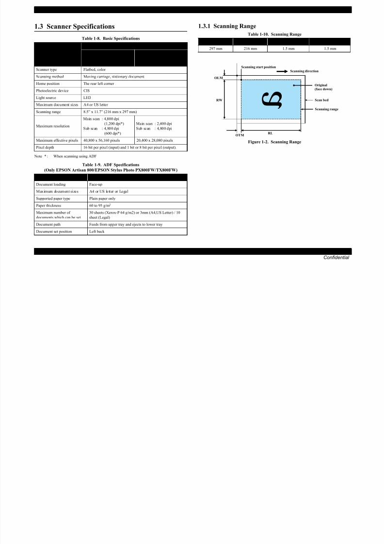
1.3 Scanner Specifications
Note * : When scanning using ADF
1.3.1 Scanning Range
Figure 1-2. Scanning Range
Table 1-8. Basic Specifications
Item
SpecificationEPSON Artisan 800/EPSON
Stylus Photo PX800FW/
TX800FW
EPSON Artisan 700/EPSON
Stylus Photo PX700W/
TX700W
Scanner type Flatbed, color
Scanning method Moving carriage, stationary document
Home position The rear left corner
Photoelectric device CIS
Light source LED
Maximum document sizes A4 or US letter
Scanning range 8.5” x 11.7” (216 mm x 297 mm)
Maximum resolution
Main scan : 4,800 dpi
(1,200 dpi*)
Sub scan : 4,800 dpi
(600 dpi*)
Main scan : 2,400 dpi
Sub scan : 4,800 dpi
Maximum effective pixels 40,800 x 56,160 pixels 20,400 x 28,080 pixels
Pixel depth 16 bit per pixel (input) and 1 bit or 8 bit per pixel (output).
Table 1-9. ADF Specifications
(Only EPSON Artisan 800/EPSON Stylus Photo PX800FW/TX800FW)
Item Specification
Document loading Face-upMaximum document sizes A4 or US letter or Legal
Supported paper type Plain paper only
Paper thickness 60 to 95 g/m2
Maximum number of
documents which can be set
30 sheets (Xerox-P 64 g/m2) or 3mm (A4,US Letter) / 10
sheet (Legal)
Document path Feeds from upper tray and ejects to lower tray
Document set position Left back
Table 1-10. Scanning Range
RL (read length) RW (read width) OLM (left margin) OTM (top margin)
297 mm 216 mm 1.5 mm 1.5 mm
aRW
RLOTM
OLM
Scanning start position
Scanning range
Scan bed
Original(face down)
Scanning direction
EPSON Artisan 800/EPSON Stylus Photo PX800FW/TX800FW/Artisan 700/EPSON Stylus Photo PX700W/TX700W Revision A

8/22/2019 TX 700 800
http://slidepdf.com/reader/full/tx-700-800 18/234
EPSON Artisan 800/EPSON Stylus Photo PX800FW/TX800FW/Artisan 700/EPSON Stylus Photo PX700W/TX700W Revision A
PRODUCT DESCRIPTION General Specifications 18
Confidential
1.4 General Specifications
1.4.1 Electrical Specifications
Note : If the product has been idle status over 13 minutes, it goes into sleep mode within 2
minutes.
1.4.2 Safety Approvals (Safety standards/EMI)
USA UL60950-1
FCC Part15 Subpart B Class B
Canada CAN/CSA-C22.2 No.60950-1
CAN/CSA-CEI/IEC CISPR 22 Class B
Mexico NOM-019-SCFI-1998
Taiwan*2 CNS13438 Class B
CNS14336
EU EN60950-1
EN55022 Class B
EN61000-3-2, EN61000-3-3
EN55024
Germany EN60950-1 Russia GOST-R (IEC60950-1, CISPR 22)
Singapore*1 IEC60950-1
Korea K60950-1
KN22 Class B
KN61000-4-2/-3/-4/-5/-6/-11
China*2 GB4943
GB9254 Class B, GB17625.1
Hong Kong*2 IEC60950-1
Argentina*1 IEC60950-1 Australia AS/NZS CISPR22 Class B
Note *1: Only EPSON Artisan 700/EPSON Stylus Photo PX700W/TX700W
*2 : Only EPSON Artisan 800/EPSON Stylus Photo PX800FW/TX800FW
1.4.3 Acoustic Noise
EPSON Artisan 800/EPSON Stylus Photo PX800FW/TX800FW
PC Printing*1: T.B.D. dB
Scanning*2: T.B.D. dB
EPSON Artisan 700/EPSON Stylus Photo PX700W/TX700W
PC Printing*1: 35 dB
Scanning*2: 27 dB
Note *1: Premium Glossy Photo Paper/Highest quality
*2 : default setting
Table 1-11. Primary Power Specifications
Item
EPSON Artisan 800/EPSON
Stylus Photo PX800FW/
TX800FW
EPSON Artisan 700/EPSON
Stylus Photo PX700W/TX700W
100-120 V
model
220-240 V
model
100-120 V
model
220-240 V
model
Rated power
supply voltage
100 to 120
VAC
220 to 240
VAC
100 to 120
VAC
220 to 240
VAC
Input voltage range90 to 132
VAC
198 to 264
VAC
90 to 132
VAC
198 to 264
VAC
Rated current
(Max. rated current)
0.8 A
(1.6 A)
0.4 A
(0.8 A)
0.8 A
(1.6 A)
0.4 A
(0.8 A)
Rated frequency 50 to 60 Hz 50 to 60 Hz
Input frequency range 49.5 to 60.5 Hz 49.5 to 60.5 Hz
Energy conservation International Energy Star Program compliant
Power
consumption
Copy
(ISO/
IEC24712
Pattern)
Approx. 26 W Approx. 26 W Approx. 25 W Approx. 25 W
Ready Approx. 12 W Approx. 12 W Approx. 9.5 W Approx. 9.5 W
Sleep Approx. 5.5 W Approx. 5.5 W Approx. 5.0 W Approx. 5.0 W
Off Approx. 0.3 W Approx. 0.5 W Approx. 0.3 W Approx. 0.5 W
EPSON Artisan 800/EPSON Stylus Photo PX800FW/TX800FW/Artisan 700/EPSON Stylus Photo PX700W/TX700W Revision A
8/22/2019 TX 700 800
http://slidepdf.com/reader/full/tx-700-800 19/234
EPSON Artisan 800/EPSON Stylus Photo PX800FW/TX800FW/Artisan 700/EPSON Stylus Photo PX700W/TX700W Revision A
PRODUCT DESCRIPTION General Specifications 19
Confidential
1.4.4 Durability
Note * : Only EPSON Artisan 800/EPSON Stylus Photo PX800FW/TX800FW
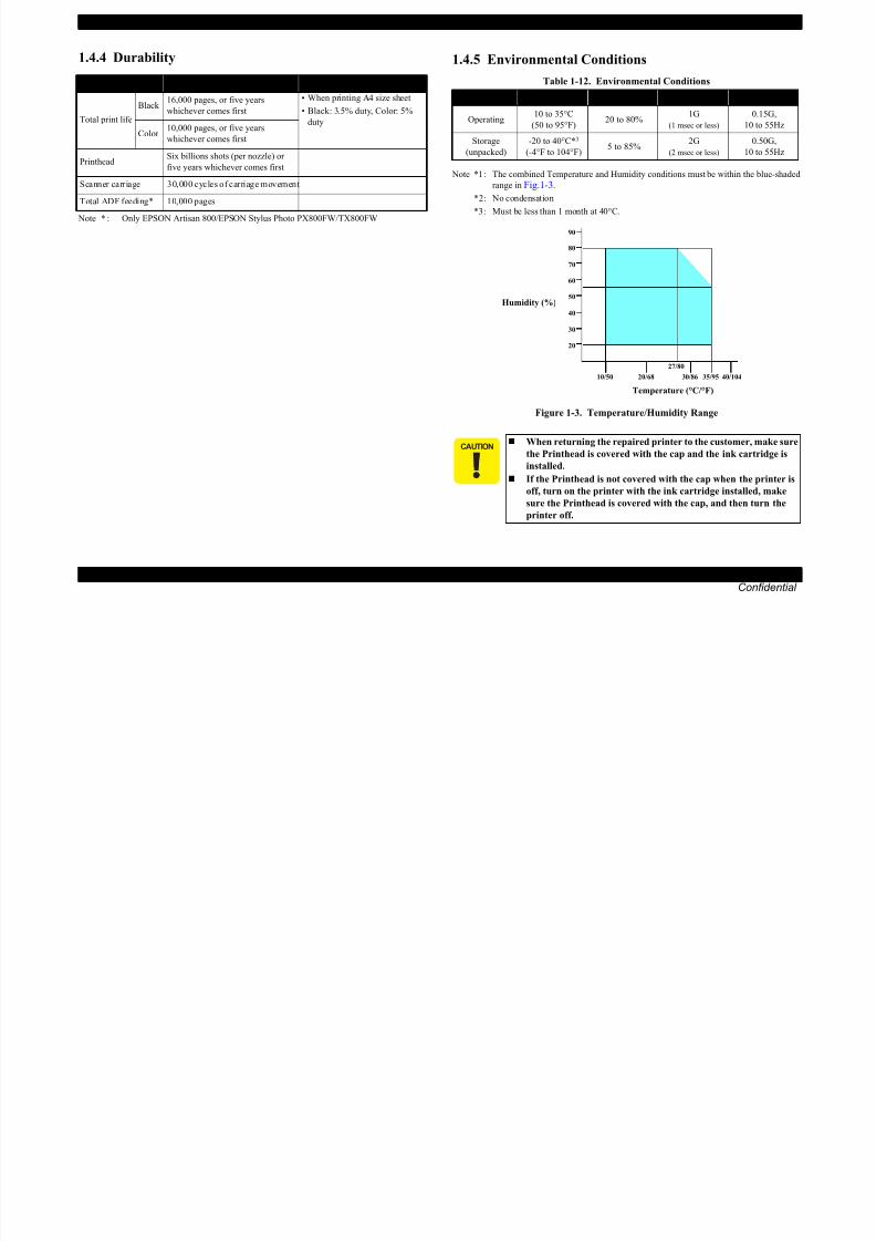
1.4.5 Environmental Conditions
Note *1 : The combined Temperature and Humidity conditions must be within the blue-shaded
range in Fig.1-3.
*2 : No condensation
*3 : Must be less than 1 month at 40°C.
Figure 1-3. Temperature/Humidity Range
Item Durability Remark
Total print lifeBlack
16,000 pages, or five years
whichever comes first
• When printing A4 size sheet
• Black: 3.5% duty, Color: 5%duty
Color 10,000 pages, or five years
whichever comes first
PrintheadSix billions shots (per nozzle) or
five years whichever comes first
Scanner carriage 30,000 cycles of carriage movement
Total ADF feeding* 10,000 pages
Table 1-12. Environmental Conditions
Condition Temperature*1 Humidity*1,2 Shock Vibration
Operating10 to 35°C
(50 to 95°F)20 to 80%
1G
(1 msec or less)
0.15G,
10 to 55Hz
Storage
(unpacked)
-20 to 40°C*3
(-4°F to 104°F)5 to 85%
2G
(2 msec or less)
0.50G,
10 to 55Hz
When returning the repaired printer to the customer, make sure
the Printhead is covered with the cap and the ink cartridge is
installed.
If the Printhead is not covered with the cap when the printer is
off, turn on the printer with the ink cartridge installed, make
sure the Printhead is covered with the cap, and then turn the
printer off.
10/50
27/80
35/9520/68
Temperature (°C/°F)
20
30
40
50
90
80
70
60
Humidity (%)
30/86 40/104

8/22/2019 TX 700 800
http://slidepdf.com/reader/full/tx-700-800 20/234
EPSON Artisan 800/EPSON Stylus Photo PX800FW/TX800FW/Artisan 700/EPSON Stylus Photo PX700W/TX700W Revision A
8/22/2019 TX 700 800
http://slidepdf.com/reader/full/tx-700-800 21/234
y y
PRODUCT DESCRIPTION Interface 21
Confidential
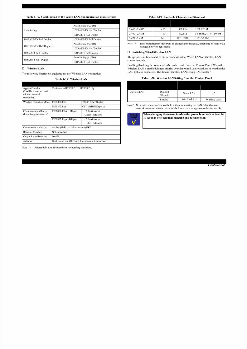
Wireless LAN
The following interface is equipped for the Wireless LAN connection.
Note * : Referential value. It depends on surrounding conditions.
Note " * " : The communication speed will be changed automatically, depending on radio wave
strength. bps = bit per second.
Switching Wired/Wireless LAN
This printer can be connect to the network via either Wired LAN or Wireless LAN
connection only.
Enabling/disabling the Wireless LAN can be made from the Control Panel. When the
Wireless LAN is enabled, it gets priority over the Wired Lan regardless of whether the
LAN Cable is connected. The default Wireless LAN setting is “Disabled”.
Note* : No service via network is available without connecting the LAN Cable (because
network communication is not established.) except printing a status sheet or the like.
Table 1-17. Combination of the Wired LAN communication mode settings
Setting of this printer Setting of the connected device
Auto Setting
Auto Setting (AUTO)
100BASE-TX Half Duplex
10BASE-T Half Duplex
100BASE-TX Full Duplex 100BASE-TX Full Duplex
100BASE-TX Half DuplexAuto Setting (AUTO)
100BASE-TX Half Duplex
10BASE-T Full Duplex 10BASE-T Full Duplex
10BASE-T Half Duplex
Auto Setting (AUTO)
10BASE-T Half Duplex
Table 1-18. Wireless LAN
Item Content
Applied Standard
(2.4GHz spectrum band
wireless network
standards)
Conforms to IEEE802.11b, IEEE802.11g
Wireless Operation Mode IEEE802.11b DS-SS (Half Duplex)
IEEE802.11g OFDM (Half Duplex)
Communication Range
(line-of-sight distance)*
IEEE802.11b (11Mbps) • 60m (indoor)
• 220m (outdoor)
IEEE802.11g (54Mbps) • 20m (indoor) • 100m (outdoor)
Communication Mode Ad-hoc (IBSS) or Infrastructure (ESS)
Roaming Function Not supported
Output Signal Intensity 10mW
Antenna Built-in antenna (Diversity function is not supported)
Table 1-19. Available Channels and Standard
Frequency Band
(GHz)Channel IEEE Standard
Communication Speed
(bps)*
2.400 - 2.4835 1 - 13 802.11b 11/5.5/2/1M
2.400 - 2.4835 1 - 13 802.11g 54/48/36/24/18/ 12/9/6M
2.471 - 2.497 14 802.11/11b 11/ 5.5/2/1M
Table 1-20. Wireless LAN Setting from the Control Panel
Setting from Control PanelLAN Cable Connection State
Connected Disconnected
Wireless LAN Disabled
(Default)Wired LAN ---*
Enabled Wireless LAN Wireless LAN
When changing the networks while the power is on, wait at least for
10 seconds between disconnecting and reconnecting.
8/22/2019 TX 700 800
http://slidepdf.com/reader/full/tx-700-800 22/234
EPSON Artisan 800/EPSON Stylus Photo PX800FW/TX800FW/Artisan 700/EPSON Stylus Photo PX700W/TX700W Revision A

8/22/2019 TX 700 800
http://slidepdf.com/reader/full/tx-700-800 23/234
PRODUCT DESCRIPTION Control Panel 23
Confidential
1.6 Control Panel
1.6.1 Operation Buttons & LEDs
Figure 1-4. Control Panel (EPSON Artisan 800/EPSON Stylus Photo PX800FW/TX800FW)
Figure 1-5. Control Panel (EPSON Artisan 700/EPSON Stylus Photo PX700W/TX700W)
LCD
Power LED
Power Button
CD Tray button
Touch Panel
Unlock button
Blue status light
LCD
Mode button
Display/Crop button Cross Key and OK buttonMenu button
Start button
Stop/Clear Settings button
-, + button
Auto Correct button
Unlock button
Print Tray button
Power button
Power LED
Back buttonBlue status light

8/22/2019 TX 700 800
http://slidepdf.com/reader/full/tx-700-800 24/234
EPSON Artisan 800/EPSON Stylus Photo PX800FW/TX800FW/Artisan 700/EPSON Stylus Photo PX700W/TX700W Revision A

8/22/2019 TX 700 800
http://slidepdf.com/reader/full/tx-700-800 25/234
PRODUCT DESCRIPTION Control Panel 25
Confidential
Copy Photo Copy Color Restoration Off
Paper Size 4 x 6 (10 x 15)
Paper Type Prem. Glossy
Boderless On
Expansion Standard
Fix Photo Fix Photo Off
Filter Off
CD/DVD Print CD Inner/Outer Standard
Print Type Print on a CD/DVD
Document Type Text & ImageQuality Best
Print Photo • Print All Photos
• View and Print Photos
• Print Proof Sheet
• Photo Layout Sheet
• Print Index Sheet
• Slide Show
Select Photos Select All Photos
Paper Size 4 x 6 (10 x 15)
Paper Type Prem. Glossy
Borderless On
Layout Boderless
Quality Standard
Borderless On
Date Off
Print Info. On Photos Off
Fit Frame On
Bidirectional On
Fix Photo Fix Photo On
Scene Detection Automatic
Fix Red-Eye Off - This photo
Filter Off
Brightness Standard
Contrast Standard
Sharpness Standard
Saturation Standard
Print Proof SheetPaper Paper Size 4 x 6 (10 x 15)
Paper Type Prem. Glossy
infomation File name
Table 1-25. Timing of Saving or Initializing Control Panel Settings
Mode Print Setting Default Value
Print Photo Photo Layout Sheet Layout 2-up
Paper Size 4 x 6 (10 x 15)
Paper Type Prem. Glossy
Layout Method Automatic layout
Photo Layout Place this photo
Quality Standard
Expansion Standard
Date Off
Print Info. On Photos Off
Fit Frame OnBidirectional On
Print Index Sheet Expansion Standard
CD/DVD Print Layout CD/DVD 1-up
Layout Method Automatic layout
Photo Layout Place this photo
CD Inner/Outer Standard
Print Type Print on a CD/DVD
CD Density Standard Density
Fix Photo Fix Photo On
Scene Detection Automatic
Fix Red-Eye Off - This photo
Filter Off
Brightness Standard
Sharpness Standard
Saturation Standard
Table 1-25. Timing of Saving or Initializing Control Panel Settings
Mode Print Setting Default Value
EPSON Artisan 800/EPSON Stylus Photo PX800FW/TX800FW/Artisan 700/EPSON Stylus Photo PX700W/TX700W Revision A

8/22/2019 TX 700 800
http://slidepdf.com/reader/full/tx-700-800 26/234
PRODUCT DESCRIPTION Specification for Each Function 26
Confidential
Note : For the default value in FAX mode, refer to“ 1.7.5 FAX Function (FAX Mode) ( p. 40 ) ”.
1.7 Specification for Each Function
1.7.1 Stand-alone Copy Function (Copy Mode)
1.7.1.1 Supported Paper and Copy Mode
Note *1 : Supported only for EAI.
*2 : Supported only for Euro/Asia.
*3 : In the case of 4 x 6.
Note : In the case of copy using ADF, only the plain paper is available (Only EPSONArtisan 800/EPSON Stylus Photo PX800FW/TX800FW).
Print Photo Greeting Photo Card Paper Size • EAI: Letter
• Euro/Asia: A4
Paper Type Prem. Glossy
Layout • EAI: 3-up
• Euro/Asia: Borderless
Frame Off
Fix Photo Fix Photo On
Scene Detection Automatic
Fix Red-Eye Off - This photo
Filter Off
Brightness StandardContrast Highest
Sharpness Standard
Saturation Standard
Play Movie and Print Photos
(Only EPSON Artisan 800/EPSON
Stylus Photo PX800FW/TX800FW)
Paper Size 4 x 6
Paper Type Prem. Glossy
Layout • Borderless
(Print 1 Frame)
• 12-up (Print N Frame)
Quality Standard Quality
Expansion Standard
Fit Frame On
Bidirectional On
Movie Enhance On
Fix Photo Fix Photo On
Filter Off Brightness Standard
Contrast Standard
Sharpness Standard
Saturation Standard
Table 1-25. Timing of Saving or Initializing Control Panel Settings
Mode Print Setting Default Value
Table 1-26. Supported Paper and Copy Mode
Paper Type
(UI notation)Size
QualityResolution
Dot
SizeBi-d
Micro
Weave
PlainA4, A5*2
Letter*1
Draft 360x180 Eco ON OFF
Standard 360x360 MC2-1 ON OFF
Best 720x720 MC1-1 ON ON
Matte A4, Letter*1
Standard 720x720 MC2-2 ON ON
BestSMGA
5760x1440MC1-5 ON ON
Glossy/Glossy
Paper
Letter*1, A4,
5x7*2, 4x6
Standard*3 720x720 MC1-2 ON ON
Standard 720x720 MC2-2 ON ON
BestSMGA
5760x1440
MC1-5 ON ON
Prem. Glossy
Letter*1, A4,
5 x 7, 8 x 10*1,
4 x 6
Standard*3 720x720 MC1-2 ON ON
Standard 720x720 MC2-2 ON ON
BestSMGA
5760x1440MC1-5 ON ON
Ultra Glossy
Letter*1, A4,
5 x 7, 8 x 10*1,
4 x 6
Standard*3 720x720 MC1-2 ON ON
Standard 720x720 MC2-2 ON ON
BestSMGA
5760x1440MC1-5 ON ON
CD/DVD CD/DVD BestSMGA
5760x1440MC1-5 ON ON
EPSON Artisan 800/EPSON Stylus Photo PX800FW/TX800FW/Artisan 700/EPSON Stylus Photo PX700W/TX700W Revision A

8/22/2019 TX 700 800
http://slidepdf.com/reader/full/tx-700-800 27/234
PRODUCT DESCRIPTION Specification for Each Function 27
Confidential
1.7.1.2 Stand-alone Copy Menu
The stand-alone copy mode menu for the EPSON Artisan 800/EPSON Stylus Photo
PX800FW/TX800FW/Artisan 700/EPSON Stylus Photo PX700W/TX700W (settable
items) are shown in the following tables.
Note *1 : Available when the Double-sided Printing Unit is installed.
*2 : Percentages in parentheses indicate the proportion of the margin level to the
maximum which bleeds off the edges of paper.
Note : When selecting the photo copy, “color restoration/filter” settings become available in
addition to the above print settings.
Note * : The layouts are available only when the duplex unit is installed. Note : In the case of copy using ADF, only the plain paper is available.
(Only EPSON Artisan 800/EPSON Stylus Photo PX800FW/TX800FW)
Table 1-27. Copy Menus
Menu Function
Number of copies Sets the number of copies within the range of 1 to 99.
Copy type Selects either color or monochrome.
Layout Selects from layouts shown in Table 1-28.
Double-sided printing*1 Selects either “On” or “Off”.
setting
Paper type Selects paper type from the options shown in Table 1-26.Paper size Selects paper size from the options shown in Table 1-26.
Quality Selects print quality from the options shown in Table 1-26.
Zoom
Selects zoom type from the 13 types below.
• Actual
(Sets any zoom with +/- key (25% to 400%) after selecting “Actual”)
• Auto Fit Page
• Legal > Letter
• Letter > 4x6• 4x6 > Letter
• Letter > 5x7
• 5x7 > Letter
• 4x6 > A4
• A4 > 4x6
• 5x7 > A4
• A4 > 5x7
• 4x6 > 8x10
• 8x10 > 5x7
Document Type Selects from “Text”, “Text & Image”, “Photo”
Density Selects from the nine density levels of -4 to +/-0 to +4.
Expansion
(for borderless print)
Selects the margins level (margins bleed off the edges of paper)
from the Standard (100%), Mid. (50%) or Min. (0%).*2
Table 1-28. Copy Layout
Layout Description
With Border Makes a copy with 3mm of left/right/top/bottom white margins.
Borderless Makes a copy with no white margins.2-Sided 1-up* Makes a double-sided copy of two sheets.
Book/2-Sided* Makes a double-sided copy of two pages of a book.
2-up Copy Make a scaling down copy of two sheets of A4 or B5 on one sheet.
2-Sided 2-up* Make a scaling down double-sided copy of four sheets of A4 or B5.
Book/2-upMake a scaling down copy of two pages of an A4 or B5 book on
one sheet.
EPSON Artisan 800/EPSON Stylus Photo PX800FW/TX800FW/Artisan 700/EPSON Stylus Photo PX700W/TX700W Revision A

8/22/2019 TX 700 800
http://slidepdf.com/reader/full/tx-700-800 28/234
PRODUCT DESCRIPTION Specification for Each Function 28
Confidential
1.7.1.3 Copy Speed (TBD)
Not using ADF
Using ADF
(Only EPSON Artisan 800/EPSON Stylus Photo PX800FW/TX800FW)
1.7.1.4 Relation Between Original and Copy
The scanning start position is located on the front right of the scan bed. The relations
between the original placed face down and its copy are as follows.
Figure 1-6. Relation Between Original and Copy (Borderless/With Borders)
Table 1-29. Copy Speed (Plain Paper)
Copy Conditions Copy Speed(eMemo3, A4/Letter size)
Draft
360x180
Monochrome copy 39/40 cpm
Color copy 39/39 cpm
Default
360x360
Monochrome copy 18.3/18.5 cpm
Color copy 17.7/18.0 cpm
Table 1-30. Copy Speed
Copy ConditionsCopy Speed
per copy per five copies
DefaultMonochrome copy 3.1 cpm 3.0 cpm
Color copy 1.1 cpm 1.7 cpm
BestMonochrome copy 0.8 cpm 0.4 cpm
Color copy 0.8 cpm 0.4 cpm
Original Document
A Scan bed ---
B Scan area “ 1-10 Scanning Range ” (p.17)
C Original (face down) ---
OTM Top margin (out of scan range) “ 1-10 Scanning Range ” (p.17)
OLM Left margin (out of scan range) “ 1-10 Scanning Range ” (p.17)
Copied Document
D Copied paper ---
E Print area “ 1-7 Printing Area (Margins) ” (p.16)
F Copy ---
LM, RM Left margin, Right margin* “ 1-7 Printing Area (Margins) ” (p.16)
TM, BM Top margin, Bottom margin*
a
a
a
a
Scan / Print direction
A
A
B
B
C
C
DD
E
E
F F
Readable Length
Paper Length
PaperWidth
Paper Length
ReadableWidth
Readable LengthOTM
OTM
OLM
LM LM
RMRM
TM BMTM
OLMHome position
Home position
Standard copy Borderless copy
BM

8/22/2019 TX 700 800
http://slidepdf.com/reader/full/tx-700-800 29/234

8/22/2019 TX 700 800
http://slidepdf.com/reader/full/tx-700-800 30/234
EPSON Artisan 800/EPSON Stylus Photo PX800FW/TX800FW/Artisan 700/EPSON Stylus Photo PX700W/TX700W Revision A
8/22/2019 TX 700 800
http://slidepdf.com/reader/full/tx-700-800 31/234
PRODUCT DESCRIPTION Specification for Each Function 31
Confidential
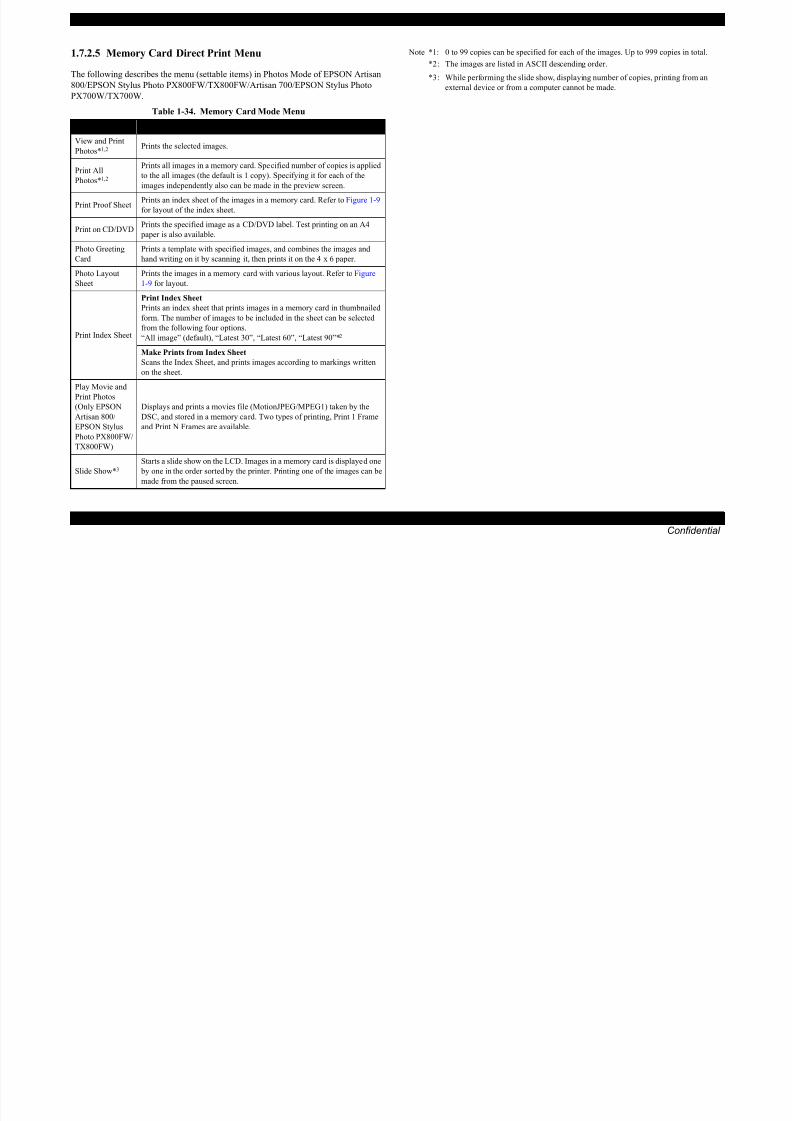
1.7.2.5 Memory Card Direct Print Menu
The following describes the menu (settable items) in Photos Mode of EPSON Artisan
800/EPSON Stylus Photo PX800FW/TX800FW/Artisan 700/EPSON Stylus Photo
PX700W/TX700W.
Note *1: 0 to 99 copies can be specified for each of the images. Up to 999 copies in total.
*2 : The images are listed in ASCII descending order.
*3 : While performing the slide show, displaying number of copies, printing from an
external device or from a computer cannot be made.
Table 1-34. Memory Card Mode Menu
Menu Item Function
View and Print
Photos*1,2 Prints the selected images.
Print All
Photos*1,2
Prints all images in a memory card. Specified number of copies is applied
to the all images (the default is 1 copy). Specifying it for each of the
images independently also can be made in the preview screen.
Print Proof SheetPrints an index sheet of the images in a memory card. Refer to Figure 1-9
for layout of the index sheet.
Print on CD/DVDPrints the specified image as a CD/DVD label. Test printing on an A4
paper is also available.
Photo Greeting
Card
Prints a template with specified images, and combines the images and
hand writing on it by scanning it, then prints it on the 4 x 6 paper.
Photo Layout
Sheet
Prints the images in a memory card with various layout. Refer to Figure
1-9 for layout.
Print Index Sheet
Print Index Sheet
Prints an index sheet that prints images in a memory card in thumbnailed
form. The number of images to be included in the sheet can be selected
from the following four options.
“All image” (default), “Latest 30”, “Latest 60”, “Latest 90”*2
Make Prints from Index Sheet
Scans the Index Sheet, and prints images according to markings written
on the sheet.
Play Movie andPrint Photos
(Only EPSON
Artisan 800/
EPSON Stylus
Photo PX800FW/
TX800FW)
Displays and prints a movies file (MotionJPEG/MPEG1) taken by the
DSC, and stored in a memory card. Two types of printing, Print 1 Frame
and Print N Frames are available.
Slide Show*3
Starts a slide show on the LCD. Images in a memory card is displayed one
by one in the order sorted by the printer. Printing one of the images can be
made from the paused screen.

8/22/2019 TX 700 800
http://slidepdf.com/reader/full/tx-700-800 32/234
EPSON Artisan 800/EPSON Stylus Photo PX800FW/TX800FW/Artisan 700/EPSON Stylus Photo PX700W/TX700W Revision A
8/22/2019 TX 700 800
http://slidepdf.com/reader/full/tx-700-800 33/234
PRODUCT DESCRIPTION Specification for Each Function 33
Confidential
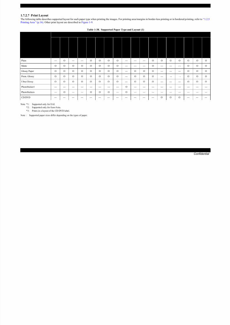
1.7.2.7 Print Layout
The following table describes supported layout for each paper type when printing the images. For printing area/margins in border-less printing or in bordered printing, refer to “ 1.2.5
Printing Area ” (p.16). Other print layout are described in Figure 1-9.
Note *1: Supported only for EAI.
*2: Supported only for Euro/Asia.
*3: Prints in a layout of the CD/DVD label. Note : Supported paper sizes differ depending on the types of paper.
Table 1-38. Supported Paper Type and Layout (1)
Paper Type
(UI notation)
Corresponding Layout
B o r d e r l e s s
W i t h B o r d e r
U p p e r 1 / 2
L o w e r 1 / 2
2 u p
4 u p
8 u p
2 0 u p
1 6 u p * 2
I n d e x - 2 0 u p
I n d e x - 3 0 u p
I n d e x - 8 0 u p
C
D ( W i t h B o r d e r )
C D - 4 u p
C D - v a r i e t y
J e w e l C a s e -
U p p e r 1 / 2
J e w e l C a s e -
I n d e x
P i c t u r e P a c k a g e * 1
Plain --- O --- --- O O O O --- --- --- O O O O O O O
Matte O O O O O O O O --- --- --- O --- --- --- O O O
Glossy Paper O O O O O O O O --- O O O --- --- --- O O O
Prem. Glossy O O O O O O O O --- O O O --- --- --- O O O
Ultra Glossy O O O O O O O O --- O O O --- --- --- O O O
PhotoSticker1 --- --- --- --- --- --- --- --- O --- --- --- --- --- --- --- --- ---
PhotoStickers --- O --- --- O O O --- O --- --- --- --- --- --- --- --- ---
CD/DVD --- --- --- --- --- --- --- --- --- --- --- --- O O O --- --- ---
EPSON Artisan 800/EPSON Stylus Photo PX800FW/TX800FW/Artisan 700/EPSON Stylus Photo PX700W/TX700W Revision A

8/22/2019 TX 700 800
http://slidepdf.com/reader/full/tx-700-800 34/234
PRODUCT DESCRIPTION Specification for Each Function 34
Confidential
Note *1: Supported only for EAI.
*2: Supported only for Euro/Asia.
*3: Prints in a layout of the CD/DVD label.
Note : Supported paper sizes differ depending on the types of paper.
Table 1-39. Supported Paper Type and Layout (2)
Paper Type
(UI notation)
Corresponding Layout
P h o t o I D
P I F - 1 u p * 2
P I F - n u p * 2
C a m e r a T e x t
I n d e x S h e e t /
P h o t o G r e e t i n g C a r d S h
e e t
P h o t o G r e e t i n g C a r d -
3 u p - G r e e t i n g C a r d * 1
P h o t o G r e e t i n g C a r d 1 u p
( B o r d e r l e s s / w i t h B o r d e
r )
P h o t o G r e e t i n g C a r d -
U p p e r 1 / 2
P h o t o G r e e t i n g C a r d -
L o w e r 1 / 2
R e p r i n t / R e s t o r e P h o t o
s
( B o r d e r l e s s / W i t h B o r d e r )
N o t e P r i n t
P l a y m o v i e a n d P r i n t P h o
t o s -
P r i n t 1 f r a m e
( B o r d e r l e s s )
P l a y m o v i e a n d P r i n t P h o
t o s -
P r i n t 1 f r a m e
( W i t h B o r d e r )
P l a y m o v i e a n d P r i n t P h o
t o s -
P r i n t 1 f r a m e
U p p e r 1 / 2
P l a y m o v i e a n d P r i n t P h o
t o s -
P r i n t 1 f r a m e
L o w e r 1 / 2
P l a y m o v i e a n d P r i n t P h o
t o s -
P r i n t 1 f r a m e
P . I . F * 2
P l a y m o v i e a n d P r i n t P h o
t o s -
P r i n t N f r a m e
1 2 u p
Plain --- O O --- O --- --- --- --- --- O --- O --- --- --- O
Matte --- O O --- --- --- --- --- --- O --- O O O O O O
Glossy Paper O O O O --- O O O O O --- O O O O O O
Prem. Glossy O O O O --- O O O O O --- O O O O O O
Ultra Glossy O O O O --- O O O O O --- O O O O O O
PhotoSticker1 --- --- --- --- --- --- --- --- --- --- --- --- --- --- --- --- ---
PhotoStickers --- O O --- --- --- --- --- --- --- --- --- --- --- --- --- ---
CD/DVD --- --- --- --- --- --- --- --- --- --- --- --- --- --- --- --- ---
EPSON Artisan 800/EPSON Stylus Photo PX800FW/TX800FW/Artisan 700/EPSON Stylus Photo PX700W/TX700W Revision A

8/22/2019 TX 700 800
http://slidepdf.com/reader/full/tx-700-800 35/234
PRODUCT DESCRIPTION Specification for Each Function 35
Confidential
Trimming Function
A trimming function is provided as a means of coordinating an image with the
types of photo frames handled by the printer. This function can be switched On/
Off. This function is described briefly below.
The printed photo frame and an image to be printed are matched in length alongone side and the image is resized along the perpendicular side to fit the frame on
that side. Any part of the image that does not fit within the photo frame is trimmed
away (not printed). However, if the number of pixels of the longer side of the
image are more than twice as long as the shortest side, the trimming function is not
effective when printing even the trimming is set. The trimming function is always
set On if borderless or upper half layout is selected.
Figure 1-7. Trimming Function (when trimming is being operated)
Figure 1-8. Trimming Function (when trimming is not operated)
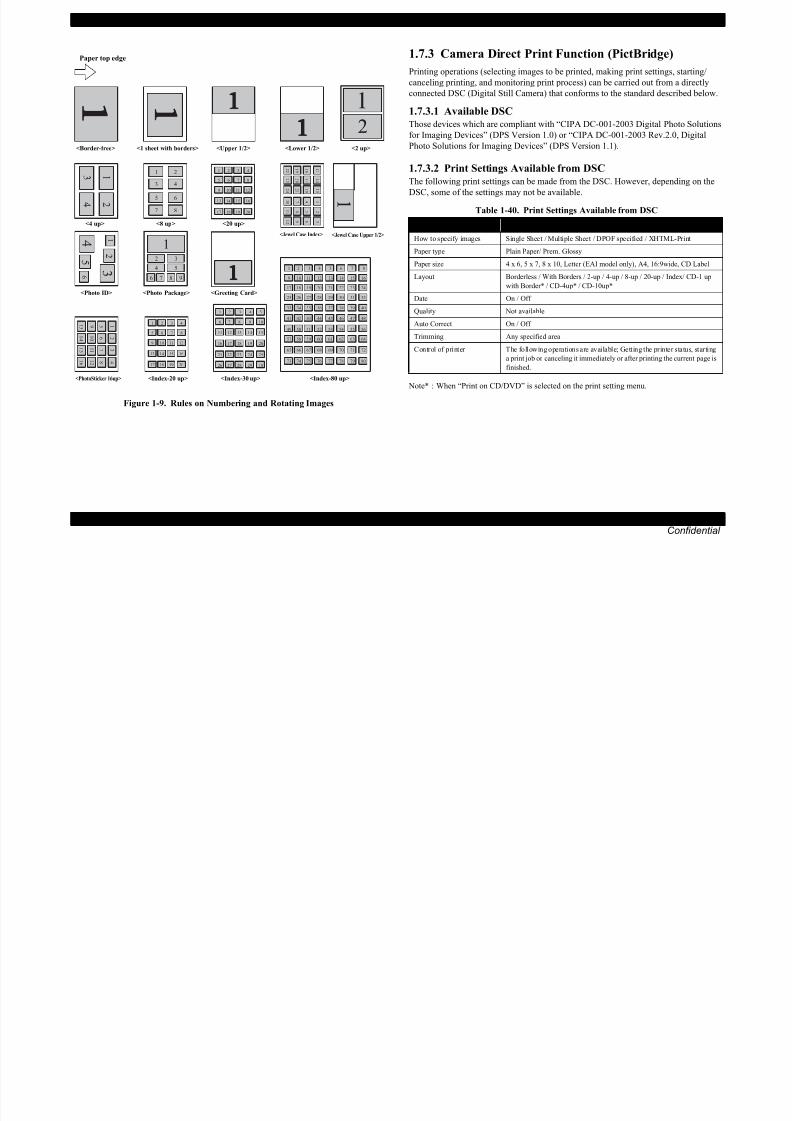
Rules on Numbering and Rotating Images
The numbers shown in the figure below indicate the photo frame numbers used for
the print layout. Horizontally oriented images are printed as shown by the
numbers. Vertically oriented images, which has more pixels vertically than
horizontally, the vertical photo data is allocated instead, and the number shown inthe figure below is then rotated 90 degrees before being printed. In Index printing
mode, the numbers are printed as they are shown below, regardless of the shape of
the photo data.
However, when the photo data has an equal number of pixels vertically and
horizontally the photos are printed without rotation, regardless of the layout.
NOTE: The vertical photo data refers to when the photo data file itself is set for a
vertical (portrait) orientation. Photo data is defined as the vertical photodata if it is taken by a digital camera with a portrait position detecting
function.)
Trimmed areas
Photo frame(print area)
• When an image is aligned vertically with the photo frame.
• When an image is aligned horizontally with the photo frame.
Photo frame(print area)
Trimmedareas
Trimming On
Blankarea
Photo frame(print area)
• When an image is aligned vertically with the photo frame.
• When an image is aligned horizontally with the photo frame.
Photo frame(print area)
Blank area
Trimming Off
EPSON Artisan 800/EPSON Stylus Photo PX800FW/TX800FW/Artisan 700/EPSON Stylus Photo PX700W/TX700W Revision A
8/22/2019 TX 700 800
http://slidepdf.com/reader/full/tx-700-800 36/234
PRODUCT DESCRIPTION Specification for Each Function 36
Confidential
Figure 1-9. Rules on Numbering and Rotating Images
1.7.3 Camera Direct Print Function (PictBridge)
Printing operations (selecting images to be printed, making print settings, starting/
canceling printing, and monitoring print process) can be carried out from a directly
connected DSC (Digital Still Camera) that conforms to the standard described below.
1.7.3.1 Available DSC
Those devices which are compliant with “CIPA DC-001-2003 Digital Photo Solutions
for Imaging Devices” (DPS Version 1.0) or “CIPA DC-001-2003 Rev.2.0, Digital
Photo Solutions for Imaging Devices” (DPS Version 1.1).
1.7.3.2 Print Settings Available from DSC
The following print settings can be made from the DSC. However, depending on the
DSC, some of the settings may not be available.
Note* : When “Print on CD/DVD” is selected on the print setting menu.
1 2
3 4
5 6
7 8
1 2 3 4
5 6 7 8
9 10 11 12
13 14 15 16
17 18 19 20
1
2
3
4
5
6
7
8
9
1 0
1 1
1 2
1 3
1 4
1 5
1 6
1 2 3 4
5 6 7 8
9 10 11 12
1
2
3
4
5
6
7
8
9
1 0
1 1
1 2
13 14 15 16
17 18 19 20
1 3
1 4
1 5
1 6
1 7
1 8
1 9
2 0
2 1
2 2
2 3
2 4
2 3 4 5
6 7 8 9 10
11 12 13 14 15
16 17 18 19 20
5
6
1
21 22 23 24
26 27 28 29 30
25
2 3 4 5 6 7 81
10 11 12 13 14 15 169
18 19 20 21 22 23 2417
26 27 28 29 30 31 3225
34 35 36 37 38 39 4033
42 43 44 45 46 47 4841
50 51 52 53 54 55 5649
58 59 60 61 62 63 6457
66 67 68 69 70 71 7265
74 75 76 77 78 79 8073
1
2 3
4 5
6 7 8 9
Paper top edge
<Border-free> <1 sheet with borders> <Upper 1/2> <Lower 1/2> <2 up>
<4 up> <8 up> <20 up>
<Photo ID>
<Index-20 up> <Index-80 up><Index-30 up>
<Photo Package>
<Jewel Case Index> <Jewel Case Upper 1/2>
<Greeting Card>
<PhotoSticker 16up>
Table 1-40. Print Settings Available from DSC
Item PictBridge
How to specify images Single Sheet / Multiple Sheet / DPOF specified / XHTML-Print
Paper type Plain Paper/ Prem. Glossy
Paper size 4 x 6, 5 x 7, 8 x 10, Letter (EAI model only), A4, 16:9wide, CD Label
Layout Borderless / With Borders / 2-up / 4-up / 8-up / 20-up / Index/ CD-1 up
with Border* / CD-4up* / CD-10up*
Date On / Off
Quality Not available
Auto Correct On / Off
Trimming Any specified area
Control of printer The following operations are available; Getting the printer status, starting
a print job or canceling it immediately or after printing the current page is
finished.

8/22/2019 TX 700 800
http://slidepdf.com/reader/full/tx-700-800 37/234
EPSON Artisan 800/EPSON Stylus Photo PX800FW/TX800FW/Artisan 700/EPSON Stylus Photo PX700W/TX700W Revision A

8/22/2019 TX 700 800
http://slidepdf.com/reader/full/tx-700-800 38/234
PRODUCT DESCRIPTION Specification for Each Function 38
Confidential
1.7.4 Various Settings (Setup Mode)
EPSON Artisan 800/EPSON Stylus Photo PX800FW/TX800FW/Artisan 700/EPSON
Stylus Photo PX700W/TX700W provides various configuration and maintenance.
They can be done by selecting “Setup” from the menu on LCD. The following explains
the outline of these menu functions.Table 1-42. Menu List for Setup Mode
Item Function
Ink Levels
The current ink levels of each of the cartridges are
displayed in bar chart by the rules described below.
• The bar chart is displayed in the order of cyan, yellow,
light cyan, black, magenta, and light magenta from the
left.
• When initial filling is completed, or after replacing thecartridge, the ink level becomes 100% (full).
• The ink level is indicated in increment of 1%. Lower than
1% is rounded down.
Maintenance
Runs various maintenance for the printer. The following
shows each menu.
• Nozzle Check
A nozzle check pattern to check the Printhead nozzles
status is printed. A head cleaning can be run if necessary.
(Refer to Figure 1-10 for Printout pattern.)• Head Cleaning
Runs a printhead cleaning. The cleaning cannot be made
when low ink level is detected. In such case, an ink low
error is displayed instead of running the cleaning.
• Head Alignment
Adjustment to improve the bi-directional print quality.
Head alignment icon and the instructions for the
adjustment are displayed on the LCD.
• Automatic Head Maintenance Selects On/Off of the auto head cleaning.
Printer Setup
Changes settings for the printer. The menu is described
below.
• CD/DVD Alignment Makes the printing position adjustment for CD/DVD
label.
• Stickers (Euro/Asia only)
Makes the printing position adjustment for Stickers.
• Thick Paper
Selects On/Off of friction reduction between paper and
printhead.
• Sound
Selects On/Off of the settings of beep sound*, audiooutput, and also selects the volume.
• Screen Saver Settings
If the panel is not used in stand-by mode, plays a slide
show using the images in a memory card as the screen-
saver.
• Display Format
The screen when displaying a photo can be selected from
the following three types.
1-up with Info 1-up without Info
View Thumbnail Images
• Use Selected P.I.F. Frame with Photo
Selects On/Off of photo printing using P.I.F frame.
• Date/Time*
• Daylight Saving Time*
• Country/Region*
• Language
Table 1-42. Menu List for Setup Mode
Item Function

8/22/2019 TX 700 800
http://slidepdf.com/reader/full/tx-700-800 39/234

8/22/2019 TX 700 800
http://slidepdf.com/reader/full/tx-700-800 40/234
EPSON Artisan 800/EPSON Stylus Photo PX800FW/TX800FW/Artisan 700/EPSON Stylus Photo PX700W/TX700W Revision A
Print User Setting

8/22/2019 TX 700 800
http://slidepdf.com/reader/full/tx-700-800 41/234
PRODUCT DESCRIPTION Specification for Each Function 41
Confidential
Note *1 : The default setting is letter for US/Canada/Mexico and A4 for other destinations.
*2 : The printer stops printing after printing the first page on the current paper. The
received fax images (data) can be reprinted.
User Setting
Note* : The display format can be changed from the Set up menu.
Function Specification
Paper size Letter/A4/legal*1
Paper type Fixed to plain paper
Resolution Standard: 360 x 360 dpi
Dot size MC2-1
Bi-directional Available
Microweave N/A
Borderless printing N/A
Automatic reduction On/Off
Backup fax reception and
reprintAvailable
List
Type: Last transaction (off/send error/every send)
Fax log (last 30 transactions)
Speed dial list
Power-fail report
Protocol trace
Font size: 12pt
Language:Depends on destination
Size mismatch Print*2
Footer N/A
Function Specification
Volume Buzzer: On/Off
Date and time
Display*: yyyy.mm.dd.hh:mm (12h/24h)
Backup: N/A
Daylight time:Available
Pending job viewer N/A (cannot reserve)
Elapsed time Available (displays time to redial)
External memory N/A
Language Depends on destination
Audio monitor Available (buzzer)
EPSON Artisan 800/EPSON Stylus Photo PX800FW/TX800FW/Artisan 700/EPSON Stylus Photo PX700W/TX700W Revision A
Dialing Answering
8/22/2019 TX 700 800
http://slidepdf.com/reader/full/tx-700-800 42/234
PRODUCT DESCRIPTION Specification for Each Function 42
Confidential
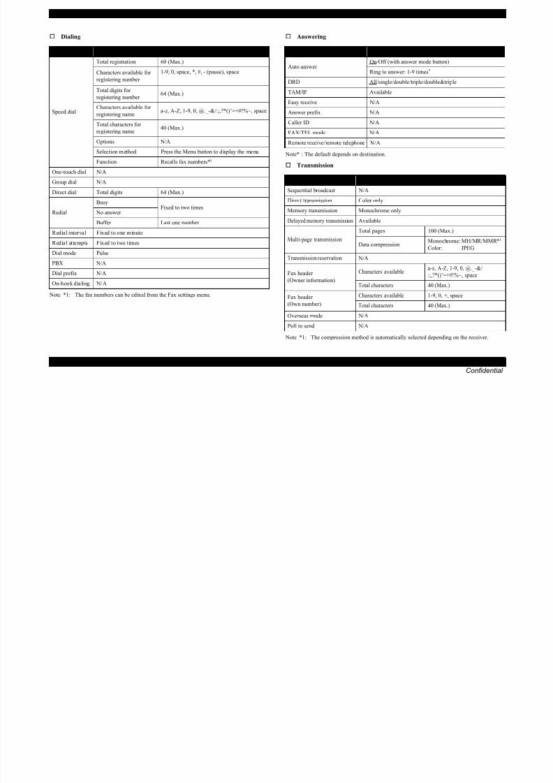
Dialing
Note *1: The fax numbers can be edited from the Fax settings menu.
Answering
Note* : The default depends on destination.
Transmission
Note *1: The compression method is automatically selected depending on the receiver.
Function Specification
Speed dial
Total registration 60 (Max.)
Characters available forregistering number
1-9, 0, space, *, #, - (pause), space
Total digits for
registering number 64 (Max.)
Characters available for
registering namea-z, A-Z, 1-9, 0, @._-&/:;,?*()’=+#!%~, space
Total characters for
registering name40 (Max.)
Options N/A
Selection method Press the Menu button to display the menu
Function Recalls fax numbers*1
One-touch dial N/A
Group dial N/A
Direct dial Total digits 64 (Max.)
RedialBusy Fixed to two times No answer
Buffer Last one number
Redial interval Fixed to one minute
Redial attempts Fixed to two times
Dial mode Pulse
PBX N/A
Dial prefix N/A
On-hook dialing N/A
Function Specification
Auto answer On/Off (with answer mode button)
Ring to answer: 1-9 times*
DRD All/single/double/triple/double&triple
TAM/IF Available
Easy receive N/A
Answer prefix N/A
Caller ID N/A
FAX/TEL mode N/A
Remote receive/remote telephone N/A
Function Specification
Sequential broadcast N/A
Direct transmission Color only
Memory transmission Monochrome only
Delayed memory transmission Available
Multi-page transmission
Total pages 100 (Max.)
Data compressionMonochrome: MH/MR/MMR*1
Color: JPEG
Transmission reservation N/A
Fax header
(Owner information)Characters available
a-z, A-Z, 1-9, 0, @._-&/
:;,?*()’=+#!%~, space
Total characters 40 (Max.)
Fax header
(Own number)
Characters available 1-9, 0, +, space
Total characters 40 (Max.)
Overseas mode N/A
Poll to send N/A
EPSON Artisan 800/EPSON Stylus Photo PX800FW/TX800FW/Artisan 700/EPSON Stylus Photo PX700W/TX700W Revision A
Reception 1.7.6 Other Functions

8/22/2019 TX 700 800
http://slidepdf.com/reader/full/tx-700-800 43/234
PRODUCT DESCRIPTION Specification for Each Function 43
Confidential
p
Communication
Telephone
Others
1.7.6 Other Functions
EPSON Artisan 800/EPSON Stylus Photo PX800FW/TX800FW/Artisan 700/EPSON
Stylus Photo PX700W/TX700W allows you to use various functions by selecting one
of the following modes from the menu on LCD.
1.7.6.1 Scan Mode
Scan to Email
Scan to Memory Card
Scan to PC
Scan to PDF
When “Scan to Memory Card” is selected, you can change settings for saving format,scanning range, document type, and saving quality according to the instructions
displayed on the LCD. After scanning, the scanned data is saved in the memory card.
As for other menus, the Epson Scan installed in PC is activated and runs each function.
1.7.6.2 Backup Data
You can save data as a back up from the file in the memory card to the file in the
externally-connected CDR drive, etc. or delete all the files in the memory card.
1.7.6.3 Print Ruled Papers
You can print ruled lines on A4 plain paper for use of a sheet of notebook or a letter by
operating according to the instructions displayed on the LCD. Ten types of ruled lines
are available.
1.7.6.4 Coloring Book (Only EPSON Artisan 800/EPSON Stylus
Photo PX800FW/TX800FW)
Scans the document on the document table, and traces the outline
automatically, and prints the outline as a coloring sheet. As the auto outline
tracing, three types of setting are available; “People”, “Scenery” and “Line
Drawing”.
Function Specification
FAX forwarding N/A
Block junk faxes N/A
Block no-ID calls N/A
Poll to receive Available
Function Specification
ECM On/Off
V.34 On/Off
Region Depends on destination
JBIG N/A
Function Specification
External telephone
Jack: Available
Handset: N/A
Hook detect: Available
Manual send: Available
Manual receive: Available
Function Specification
Power save mode Available
Receive and print during power off N/A
Copy during faxing N/A
Scan during faxing N/A
Save received data during power off N/A

8/22/2019 TX 700 800
http://slidepdf.com/reader/full/tx-700-800 44/234
Confidential
C H A P T E R
2OPERATING PRINCIPLES
EPSON Artisan 800/EPSON Stylus Photo PX800FW/TX800FW/Artisan 700/EPSON Stylus Photo PX700W/TX700W Revision A
2.1 Overview 2.1.2 Printhead

8/22/2019 TX 700 800
http://slidepdf.com/reader/full/tx-700-800 45/234
OPERATING PRINCIPLES Overview 45
Confidential
2.1 Overview
This section describes the operating principles of the Printer Mechanism of EPSON
Artisan 800/EPSON Stylus Photo PX800FW/TX800FW/Artisan 700/EPSON Stylus
Photo PX700W/TX700W.
2.1.1 Printer Mechanism
The following describes the mechanism, motors and sensors that construct the printer.
Figure 2-1. Printer Mechanism Block Diagram
Printing method : On demand inkjet (F6-Shrink head)
Nozzle
The nozzle layout as seen from behind the printhead is shown below.
Figure 2-2. Nozzle Layout
PF Encoder
PW Sensor
CR Encoder
PF Roller
EJ Roller
Carriage Assy
Printhead
CartridgeBox Unit
Ink System DecompressionMotor
(1) CDR Tray Sensor
(3) Duplex Unit Sensor
(1)
PF Motor
(2) Photo Tray Sensor
CR Motor
PE Sensor
CR Shaft
EJ Cover Open (Plunger)
(2)
(3)
CDR Tray
Intermediate
Roller
Cover OpenSensor
EJ Frame AssyLD Roller
Pick-upRoller
Color Bk, C, M, Y, Lc, Lm (6 colors)
Nozzle 1,080 nozzle (Each color 180 nozzle x 6 lines)
Nozzle pitch 0.141 mm for each line (1/180 inch)
B#180
B#179
B#178
B#3
B#2
B#1
D#180
D#179
D#178
D#3
D#2
D#1
A#180
A#179
A#178
A#3
A#2
A#1
C#180
C#179
C#178
C#3
C#2
C#1
F#180
F#179
F#178
F#3
F#2
F#1
E#180
E#179
E#178
E#3
E#2
E#1
P
a p e r f e e d d i r e c t i o n
Carriage movement direction
EPSON Artisan 800/EPSON Stylus Photo PX800FW/TX800FW/Artisan 700/EPSON Stylus Photo PX700W/TX700W Revision A
2.1.3 Motors & Sensors

8/22/2019 TX 700 800
http://slidepdf.com/reader/full/tx-700-800 46/234
OPERATING PRINCIPLES Overview 46
Confidential
The following describes the motors and sensors.
Figure 2-3. Motors & Sensors (Printer)
Table 2-1. Motors & Sensors (Printer)
Name Motors & Sensors name #
Printhead ---
Carriage mechanism
CR Motor A
CR Encoder 1
PW Sensor 2
Paper feeding mechanism
PF Motor B
PF Encoder 3
PE Sensor 4
CDR Tray Sensor 5
EJ Cover Open (Plunger) 6
Photo Tray Sensor 7
Ink Supply mechanism Decompression Motor C
Duplex Printing mechanism Duplex Unit Sensor 8
See “ 3.2.1 Motor and Sensor Troubleshooting ” (p.52) for the each
motor and sensor specification.
1
A8
5
7
4
2
6
B
3
Printhead
C
EPSON Artisan 800/EPSON Stylus Photo PX800FW/TX800FW/Artisan 700/EPSON Stylus Photo PX700W/TX700W Revision A
Table 2-2. Motors & Sensors (Scanner)

8/22/2019 TX 700 800
http://slidepdf.com/reader/full/tx-700-800 47/234
OPERATING PRINCIPLES Overview 47
Confidential
Figure 2-4. Motors & Sensors (Scanner)
Figure 2-5. Motors & Sensors (ADF)
Name Motors & Sensors name #
Scanner Carriage Unit ---
Open/close detection
mechanism Cover Open Sensor 9
Drive section of Scanner
Carriage mechanism
Scanner Motor D
Scanner CR Encoder 10
Table 2-3. Motors & Sensors (ADF)
Name Motors & Sensors name #
Paper feeding mechanismADF Motor EADF DOC Sensor 11
ADF PE Sensor 12
See “ 3.2.1 Motor and Sensor Troubleshooting ” (p.52) for the each
motor and sensor specification.
9
D
10
Scanner Carriage Unit
11
12
E
EPSON Artisan 800/EPSON Stylus Photo PX800FW/TX800FW/Artisan 700/EPSON Stylus Photo PX700W/TX700W Revision A
2.1.4 PG setting

8/22/2019 TX 700 800
http://slidepdf.com/reader/full/tx-700-800 48/234
OPERATING PRINCIPLES Overview 48
Confidential
Following is the PG setting for EPSON Artisan 800/EPSON Stylus Photo PX800FW/TX800FW/Artisan 700/EPSON Stylus Photo PX700W/TX700W.
Figure 2-6. PG positions/Cam
PG
TypePos.1
→
Pos.2
→
Pos.3
→
Pos.4
PG (-) PG (Typ) PG (+) PG (++)
PG measurement (mm) 1.2 1.7 2.35 5.8
Position name Home position Normal position PG large position PG max position
Description
Printing EPSON brand paper Plain paper printing
Avoiding friction of PG (-)
Envelope printing
Avoiding friction of PG (Typ)CD/DVD
Not printing
Capping
Wiping
Ready position after
initialization
AID
Capping Capping Capping
EJ release
Rotating direction for PF Motor
PG (-)PG (Typ)
PG (+)
PG (++)
Clockwise
EPSON Artisan 800/EPSON Stylus Photo PX800FW/TX800FW/Artisan 700/EPSON Stylus Photo PX700W/TX700W Revision A
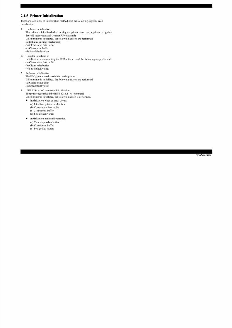
2.1.5 Printer Initialization
8/22/2019 TX 700 800
http://slidepdf.com/reader/full/tx-700-800 49/234
OPERATING PRINCIPLES Overview 49
Confidential
There are four kinds of initialization method, and the following explains each
initialization
1. Hardware initialization
This printer is initialized when turning the printer power on, or printer recognized
the cold-reset command (remote RS command).
When printer is initialized, the following actions are performed.
(a) Initializes printer mechanism
(b) Clears input data buffer
(c) Clears print buffer
(d) Sets default values
2. Operator initialization
Initialization when resetting the USB software, and the following are performed (a) Clears input data buffer
(b) Clears print buffer
(c) Sets default values
3. Software initialization
The ESC@ command also initialize the printer.
When printer is initialized, the following actions are performed.
(a) Clears print buffer
(b) Sets default values4. IEEE 1284.4 “rs” command initialization
The printer recognized the IEEE 1284.4 “rs” command.
When printer is initialized, the following action is performed.
Initialization when an error occurs.
(a) Initializes printer mechanism
(b) Clears input data buffer
(c) Clears print buffer
(d) Sets default values
Initialization in normal operation
(a) Clears input data buffer
(b) Clears print buffer
(c) Sets default values

8/22/2019 TX 700 800
http://slidepdf.com/reader/full/tx-700-800 50/234
Confidential
C H A P T E R
3TROUBLESHOOTING

8/22/2019 TX 700 800
http://slidepdf.com/reader/full/tx-700-800 51/234
EPSON Artisan 800/EPSON Stylus Photo PX800FW/TX800FW/Artisan 700/EPSON Stylus Photo PX700W/TX700W Revision A
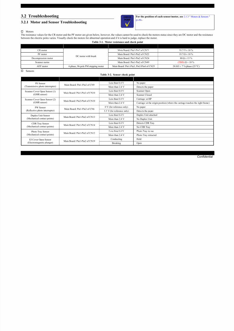
3.2 Troubleshooting
For the position of each sensor/motor, see 2.1.3 " Motors & Sensors "
(p 46)
8/22/2019 TX 700 800
http://slidepdf.com/reader/full/tx-700-800 52/234
TROUBLESHOOTING Troubleshooting 52
Confidential
3.2.1 Motor and Sensor Troubleshooting
MotorsThe resistance values for the CR motor and the PF motor are given below, however, the values cannot be used to check the motors status since they are DC motor and the resistance
between the electric poles varies. Visually check the motors for abnormal operation and if it is hard to judge, replace the motor.
Sensors
(p.46).
Table 3-1. Motor resistance and check point
Motor Motor Type Check point Resistance
CR motor
DC motor with brush
Main Board: Pin1-Pin2 of CN21 19.7 Ω ± 10 %
PF motor Main Board: Pin1-Pin2 of CN22 19.7 Ω ± 10 %
Decompression motor Main Board: Pin1-Pin2 of CN24 88 Ω ± 15 %Scanner motor Main Board: Pin1-Pin2 of CN49 (TBD) Ω ± 10 %
ADF motor 4-phase, 96-pole PM stepping motor Main Board: Pin1-Pin3, Pin2-Pin4 of CN25 28.0 Ω ± 7 %/phase (25 oC)
Table 3-2. Sensor check point
Sensor name Check point Signal level Switch mode
PE Sensor
(Transmissive photo interrupter)
Main Board: Pin1-Pin2 of CN9Less than 0.4 V No paper
More than 2.4 V Detects the paper
Scanner Cover Open Sensor (1)
(GMR sensor)Main Board: Pin1-Pin2 of CN10
Less than 0.4 V Scanner Open
More than 2.4 V Scanner Closed
Scanner Cover Open Sensor (2)
(GMR sensor)Main Board: Pin2-Pin4 of CN10
Less than 0.4 V Carriage: at HP
More than 2.4 V Carriage: at the origin position (where the carriage touches the right frame)
PW Sensor
(Reflective photo interrupter)Main Board: Pin1-Pin3 of CN6
0 V (for reference only) No paper
3.3 V (for reference only) Detects the paper
Duplex Unit Sensor (Mechanical contact points)
Main Board: Pin1-Pin2 of CN13 Less than 0.4 V Duplex Unit attachedMore than 2.4 V No Duplex Unit
CDR Tray Sensor
(Mechanical contact points)Main Board: Pin1-Pin2 of CN14
Less than 0.4 V Detects CDR Tray
More than 2.4 V No CDR Tray
Photo Tray Sensor
(Mechanical contact points)Main Board: Pin1-Pin2 of CN12
Less than 0.4 V Photo Tray in use
More than 2.4 V Photo Tray retracted
EJ Cover Open Sensor
(Electromagnetic plunger)
Main Board: Pin1-Pin2 of CN19Conducting Hold
Breaking Open

8/22/2019 TX 700 800
http://slidepdf.com/reader/full/tx-700-800 53/234
EPSON Artisan 800/EPSON Stylus Photo PX800FW/TX800FW/Artisan 700/EPSON Stylus Photo PX700W/TX700W Revision A
Table 3-3. Error Indications and Fault Occurrence Causes
Error Name LCD Message Error Cause Reference
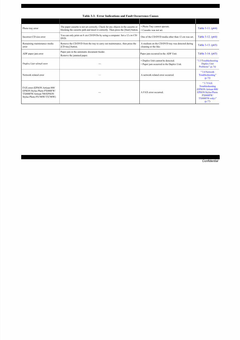
8/22/2019 TX 700 800
http://slidepdf.com/reader/full/tx-700-800 54/234
TROUBLESHOOTING Troubleshooting by Error Message 54
Confidential
Photo tray error The paper cassette is not set correctly. Check for any objects in the cassette or
blocking the cassette path and insert it correctly. Then press the [Start] button.
• Photo Tray cannot operate.
• Cassette was not set.Table 3-11. (p64)
Incorrect CD size error You can only print on 8 cm CD/DVDs by using a computer. Set a 12 cm CD/
DVD.One of the CD/DVD media other than 12 cm was set. Table 3-12. (p64)
Remaining maintenance media
error
Remove the CD/DVD from the tray to carry out maintenance, then press the
[CD tray] button.
A medium on the CD/DVD tray was detected during
cleaning or the like.Table 3-13. (p65)
ADF paper jam error Paper jam in the automatic document feeder.
Remove the jammed paper.Paper jam occurred in the ADF Unit. Table 3-14. (p65)
Duplex Unit related error ---• Duplex Unit cannot be detected.• Paper jam occurred in the Duplex Unit.
" 3.5 TroubleshootingDuplex Unit
Problems " (p.74)
Network related error --- A network related error occurred.
" 3.6 Network
Troubleshooting "
(p.75)
FAX error (EPSON Artisan 800/
EPSON Stylus Photo PX800FW/TX800FW/Artisan 700/EPSON
Stylus Photo PX700W/TX700W)
--- A FAX error occurred.
" 3.7 FAX
Troubleshooting
(EPSON Artisan 800/EPSON Stylus Photo
PX800FW/
TX800FW only) "
(p.77)
Error Name LCD Message Error Cause Reference
EPSON Artisan 800/EPSON Stylus Photo PX800FW/TX800FW/Artisan 700/EPSON Stylus Photo PX700W/TX700W Revision A
3.3.2 Troubleshooting by Error Message
The following tables provide troubleshooting procedures Confirm the error message displayed on the LCD and verify it in the following list for the corresponding troubleshooting

8/22/2019 TX 700 800
http://slidepdf.com/reader/full/tx-700-800 55/234
TROUBLESHOOTING Troubleshooting by Error Message 55
Confidential
The following tables provide troubleshooting procedures. Confirm the error message displayed on the LCD, and verify it in the following list for the corresponding troubleshooting
remedy. If some parts need to be replaced or repaired, make sure to follow the procedure given in Chapter 4 “DISASSEMBLY/ASSEMBLY”.
Table 3-4. Check point for Fatal error according to each phenomenon (Printer Mechanism)
Occurrence
TimingSymptoms
Failed Part /
Part NameCheck Point Remedy Reference
At power-on
The CR Motor does not
operate at all.CR Motor
1. Is the CR Motor cable properly connected to CN21
connector on the Main Board?
1. Connect the CR Motor cable
correctly to CN21 connector on
the Main Board.
4.2.2.2 " Main Board /
Grounding Plate M/B "
(p.111)
2. Is the CR Motor cable damaged? 2. Replace the CR Motor with a
new one. 4.2.3.17 " CR Motor "
(p.140)3. Does the CR Motor operate normally? 3. Replace the CR Motor with anew one.
The Carriage Assy hitsagainst the right side of the
Main Frame.
CR Encoder
1. Is the CR Encoder damaged? 1. Replace the CR Encoder with a
new one. 4.2.3.18 " Carriage Unit "
(p.142)2. Is the FFC correctly connected to the connector on the
CR Encoder?
2. Connect the Head FFC correctly.
CR Scale
1. Is the CR Scale properly centered in the slit of the CR
Encoder?
1. Install the CR Scale correctly.
4.2.3.2 " CR Scale "
(p.120)
2. Is the CR Scale surface clean? 2. Wipe any dirt off the surface of
the CR Scale. When the
contamination is severe, replace
the CR Scale with a new one.
3. Is the CR Scale damaged? 3. Replace the CR Scale with a new
one.
4. Is the CR Scale correctly installed? 4. Install the CR Scale and the
torsion spring correctly.
The Carriage Assy hits
against the Upper Paper
Guide.
Upper Paper Guide
1. Is the Upper Paper Guide correctly installed? 1. Install the Upper Paper Guide
correctly.
4.2.3.21 " Upper Paper
Guide L/R / PE Sensor "
(p.148)
EPSON Artisan 800/EPSON Stylus Photo PX800FW/TX800FW/Artisan 700/EPSON Stylus Photo PX700W/TX700W Revision A
Table 3-4. Check point for Fatal error according to each phenomenon (Printer Mechanism)
OccurrenceSymptoms
Failed Part /Check Point Remedy Reference
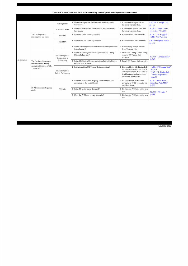
8/22/2019 TX 700 800
http://slidepdf.com/reader/full/tx-700-800 56/234
TROUBLESHOOTING Troubleshooting by Error Message 56
Confidential
At power-on
The Carriage Assy
movement is too slow.
Carriage shaft1. Is the Carriage shaft free from dirt, and adequately
lubricated?
1. Clean the Carriage shaft and
lubricate it as specified.
4.2.3.18 " Carriage Unit "
(p.142)
CR Guide Plate1. Is the CR Guide Plate free from dirt, and adequately
lubricated?
1. Clean the CR Guide Plate and
lubricate it as specified.
4.2.3.22 " Paper Guide
Front Assy " (p.150)
Ink Tube1. Is the Ink Tube correctly routed? 1. Route the Ink Tube correctly. 4.2.3.7 " Ink Supply IC
Holder Assy " (p.125)
Head FFC1. Is the Head FFC correctly routed? 1. Route the Head FFC correctly. 4.4 " Routing FFC/cables "
(p.189)
---1. Is the Carriage path contaminated with foreign material
(slip of paper)?
1. Remove any foreign material
from Carriage path. ---
The Carriage Assy makes
abnormal noise during
operation (Slipping of CR
Timing belt)
CR Timing Belt,
Timing Driven
Pulley Assy
1. Is the CR Timing Belt correctly installed to Timing
Driven Pulley Assy?
1. Install the Timing Driven Pulley
Assy to CR Timing Belt
correctly. 4.2.3.18 " Carriage Unit "
(p.142)2. Is the CR Timing Belt correctly installed to the Pinion
Gear of the CR Motor?
2. Install CR Timing Belt correctly.
CR Timing Belt,Driven Pulley Assy
1. Is tension of the CR Timing Belt appropriate? 1. Reassemble the CR Timing Belt
and check the tension of the CR
Timing Belt again. If the tension
is still not appropriate, replace
the Printer Mechanism.
• 4.2.3.18 " Carriage Unit "
(p.142)
• 5.3.2 " CR Timing Belt
Tension Adjustment "
(p.219)
PF Motor does not operate
at all.PF Motor
1. Is the PF Motor cable properly connected to CN22
connector on the Main Board?
1. Connect the PF Motor cable
correctly to CN22 connector on
the Main Board.
4.2.2.2 " Main Board /
Grounding Plate M/B "
(p.111)
2. Is the PF Motor cable damaged? 2. Replace the PF Motor with a new
one.
4.2.3.16 " PF Motor "(p.139)3. Does the PF Motor operate normally? 3. Replace the PF Motor with a new
one.
TimingSymptoms
Part NameCheck Point Remedy Reference
EPSON Artisan 800/EPSON Stylus Photo PX800FW/TX800FW/Artisan 700/EPSON Stylus Photo PX700W/TX700W Revision A
Table 3-4. Check point for Fatal error according to each phenomenon (Printer Mechanism)
OccurrenceSymptoms
Failed Part /Check Point Remedy Reference

8/22/2019 TX 700 800
http://slidepdf.com/reader/full/tx-700-800 57/234
TROUBLESHOOTING Troubleshooting by Error Message 57
Confidential
At power-on
The PF Roller makes a
quick turn and then the
error occurs.
PF Encoder
1. Is the PF Encoder FFC correctly connected to CN8
connector on the Main Board and the connector on thePF Encoder?
1. Connect the PF Encoder FFC
correctly to CN8 connector onthe Main Board.
4.2.2.2 " Main Board /
Grounding Plate M/B "(p.111)
2. Is the PF Encoder correctly installed? 2. Install the PF Encoder correctly.4.2.3.3 " PF Encoder "
(p.121)3. Is the PF Encoder damaged? 3. Replace the PF Encoder with a
new one.
PF Scale
1. Is the PF Scale surface clean? 1. Wipe any dirt off the surface of
the PF Scale. When the
contamination is severe, replace
the PF Scale with a new one. 4.2.3.4 " PF Scale " (p.122)
2. Is the PF Scale damaged? 2. Replace the PF Scale with a new
one.
The PF Motor makes
abnormal noise duringoperation (Slipping of PF
Timing Belt)
PF Timing Belt, PFTensioner
1. Is the PF Timing Belt damaged? 1. Replace the PF Timing Belt with
a new one.
• 4.2.3.4 " PF Scale "
(p.122)
• 5.3.3 " PF Timing Belt
Tension Adjustment "
(p.220)
2. Is the PF Timing Belt correctly installed to the PF
Tensioner?
2. Install the PF Timing Belt to the
PF Tensioner correctly.
3. Is the PF Timing Belt correctly installed to the PF
Motor?
3. Install the PF Timing Belt
correctly.
4. Is tension of the PF Timing Belt appropriate? 4. Reassemble PF Timing Belt if
the tension is not enough and
check the tension of the PF
Timing Belt again. If the tension
is still not appropriate, replace
the Printer Mechanism.
The Carriage Assy hits the
Changing Lever when itmoves to the 0 digit side.
Paper Guide FrontAssy
1. Does the Changing Lever correctly move? 1. Replace the Paper Guide Front
Assy with a new one. 4.2.3.22 " Paper Guide FrontAssy " (p.150)
The error occurs at power-
on before carrying out the
initial ink charge.
PW Sensor
1. Is the CR Encoder FFC correctly connected to CN6
connector on the Main Board?
1. Connect the CR Encoder FFC
correctly to CN6 on the Main
Board.
4.2.2.2 " Main Board /
Grounding Plate M/B "
(p.111)
2. Is the CR Encoder damaged? 2. Replace the Head FFC with a
new one. 4.2.3.18 " Carriage Unit "
(p.142)3. Is the PW Sensor damaged? 3. Replace the Carriage Unit with a
new one.
TimingSymptoms
Part NameCheck Point Remedy Reference

8/22/2019 TX 700 800
http://slidepdf.com/reader/full/tx-700-800 58/234
EPSON Artisan 800/EPSON Stylus Photo PX800FW/TX800FW/Artisan 700/EPSON Stylus Photo PX700W/TX700W Revision A
Table 3-4. Check point for Fatal error according to each phenomenon (Printer Mechanism)
Occurrence
Ti iSymptoms
Failed Part /
P t NCheck Point Remedy Reference

8/22/2019 TX 700 800
http://slidepdf.com/reader/full/tx-700-800 59/234
TROUBLESHOOTING Troubleshooting by Error Message 59
Confidential
• Before
printing
• Cleaning
The error occurs before
printing or cleaning.
Print Head1. Is the Print Head damaged? 1. Replace the Print Head with a
new one.4.2.3.1 " Printhead (TBD) "
(p.118)Head FFC
1. Is the Head FFC correctly connected to CN1, CN2, CN3
and CN4 on the Main Board?
1. Replace the Head FFC with a
new one.
2. Is the Head FC damaged? 2. Replace the Head FFC with a
new one.
---Other than those described
above.Main Board
1. Is the Main Board damaged? 1. Replace the Main Board with a
new one.
4.2.2.2 " Main Board /
Grounding Plate M/B "
(p.111)
Timing Part Name
Table 3-5. Check point for Fatal error according to each phenomenon (Scanner)
Occurrence
TimingSymptoms
Failed Part /
Part NameCheck Point Remedy Reference
At power-onThe Scanner Unit does not
initialize at power-on.
Scanner Motor
1. Is the Scanner Motor cable properly connected to CN49
connector on the Main Board?
1. Connect the Scanner Motor cable
correctly to CN49 connector on
the Main Board.
4.2.4.2 " Scanner Motor
Unit " (p.157)2. Is the coil resistance of the Scanner Motor TBD Ω Check with the tester. (See Table 3-1) 2. Replace the Scanner Motor cablewith a new one.
3. Is the Scanner Motor Cable damaged? 3. Replace the Scanner Motor cable
with a new one.
Scanner CR
Encoder
1. Is the Scanner CR Encoder FFC properly connected to
CN49 connector on the Main Board?
1. Connect the Scanner CR Encoder
FFC correctly to CN49 connector
on the Main Board. 4.2.4.4 " Scanner CR
Encoder Board " (p.161)2. Is the Scanner CR Encoder FFC damaged? 2. Replace the Scanner CR Encoder
FFC with a new one.
Scanner Carriage
FFC
1. Is the Scanner Carriage FFC properly connected to
CN41 connector on the Main Board?
1. Connect the Scanner Carriage
FFC correctly to CN41 connector
on the Main Board.
4.2.4.3 " Scanner Carriage
Unit " (p.158)2. Is the Scanner Carriage FFC damaged? 2. Replace the Scanner Carriage
FFC with a new one.
Scanner Carriage
Unit
1. Is the Scanner Carriage Unit damaged? 1. Replace the Scanner Carriage
FFC with a new one.
EPSON Artisan 800/EPSON Stylus Photo PX800FW/TX800FW/Artisan 700/EPSON Stylus Photo PX700W/TX700W Revision A
Table 3-6. Check point for the Maintenance request according to each phenomenon
Occurrence
Ti iSymptoms
Failed Part /
P t NCheck Point Remedy Reference

8/22/2019 TX 700 800
http://slidepdf.com/reader/full/tx-700-800 60/234
TROUBLESHOOTING Troubleshooting by Error Message 60
Confidential
Timingy p
Part Namey
Any timeThe Maintenance error is
displayed.
Waste Ink Tray
Assy/Lower Paper Guide
Waste Ink Pad
Assy
---
Replace Waste Ink Tray Assy or/and
Lower Paper Guide Waste Ink Pad
Assy and reset the waste ink
counter.
• 4.2.3.23 " Waste Ink Tray
Assy " (p.153)• 4.2.3.24 " Lower Paper
Guide Waste Ink Pad
Assy " (p.154)
EPSON Artisan 800/EPSON Stylus Photo PX800FW/TX800FW/Artisan 700/EPSON Stylus Photo PX700W/TX700W Revision A
Table 3-7. Check point for Paper jam error according to each phenomenon
Occurrence
TimingSymptoms
Failed Part /
Part NameCheck Point Remedy Reference

8/22/2019 TX 700 800
http://slidepdf.com/reader/full/tx-700-800 61/234
TROUBLESHOOTING Troubleshooting by Error Message 61
Confidential
Timing Part Name
Any time
Paper feeding operation is
performed normally, but the paper is not fed inside the
printer.
Rear Paper Guide
Assy
1. Is Rear Paper Guide Assy correctly installed? 1. Install the Rear Paper Guide
Assy correctly.
4.2.3.11 " LD Roller "
(p.132)
Lower ASF Paper
Guide Assy
1. Is Lower ASF Paper Guide Assy correctly Assy
installed?
1. Install the Lower ASF Paper
Guide Assy correctly.
4.2.3.9 " Lower ASF Paper
Guide Assy " (p.129)
2. Is the intermediate roller shaft correctly installed? 2. Install the intermediate roller
shaft correctly.
3. Is the surface of intermediate roller contaminated with
micro pearl paper dust or greasy dirt?
3. Clean the intermediate roller.
4. Does the flap of the Lower ASF Paper Guide Assy come
off?
4. Install the flap of the Lower ASF
Paper Guide correctly.
LD Roller
1. Is LD Roller shaft correctly installed? 1. Install the LD Roller shaft
correctly. 4.2.3.11 " LD Roller "
(p.132)2. Is the surface of LD Roller contaminated with micro
pearl paper dust or greasy dirt?
2. Clean the LD Roller.
Paper Guide Top
Assy
1. Is the Paper Guide Top Assy correctly installed? 1. Install the Paper Guide Top Assy
correctly.
4.2.1.13 " Paper Guide Top
Assy " (p.109)
Upper Paper Guide
L/R Assy
1. Is the Upper Paper Guide L/R Assy correctly installed? 1. Install the Upper Paper Guide L/R Assy correctly.
4.2.3.21 " Upper PaperGuide L/R / PE Sensor "
(p.148)
Multiple sheets of paper are
always fed at one time.
Cassette Unit
1. Is the Cassette Cork damaged or worn? 1. Replace the Cassette Cork with a
new one. 4.2.1.12 " Cassette Unit "
(p.108)2. Is the rear end of the Cassette Assy damaged? 2. Replace the Cassette Unit with a
new one.
Sub TransmissionCam Holder
1. Is the Sub Transmission Cam Holder correctly installed? 1. Install the Sub Transmission
Cam Holder correctly.
4.2.3.21 " Upper Paper
Guide L/R / PE Sensor "(p.148)

8/22/2019 TX 700 800
http://slidepdf.com/reader/full/tx-700-800 62/234
EPSON Artisan 800/EPSON Stylus Photo PX800FW/TX800FW/Artisan 700/EPSON Stylus Photo PX700W/TX700W Revision A
Table 3-9. Check point for the Ink End Error / No Ink Cartridge Error / Incorrect Ink Cartridge Error according to each phenomenon
Occurrence
TimingSymptoms
Failed Part /
Part NameCheck Point Remedy Reference

8/22/2019 TX 700 800
http://slidepdf.com/reader/full/tx-700-800 63/234
TROUBLESHOOTING Troubleshooting by Error Message 63
Confidential
g
At power-onThe error occurs after thecarriage detected the home position.
Ink Cartridge1. Is the Memory chip on the Ink Cartridge disconnected or
damaged?
1. Replace the Ink Cartridge with a
new one.
---
CSIC FFC1. Is the CSIC FFC properly connected to CN5 connector
on the Main Board and the connector on the CSIC Assy?
1. Connect the CSIC FFC correctly. 4.2.3.6 " CSIC Assy "
(p.124)
CSIC Assy
1. Is the CSIC terminal damaged? 1. Replace the CSIC Assy with a
new one. 4.2.3.6 " CSIC Assy "
(p.124)2. Is the CR contact module damaged? 2. Replace the CSIC Assy with a
new one.
Table 3-10. Check point for the Scanner Open Error according to each phenomenon
Occurrence
TimingSymptoms
Failed Part /
Part NameCheck Point Remedy Reference
Any timeThe Printer Cover is closed, but the cover open error isdisplayed.
Scanner Cover
Open Sensor FFC
1. Is the Scanner Cover Open Sensor FFC properly
connected to CN10 connector on the Main Board?
1. Replace the Scanner Unit with a
new one.
• 4.2.4 " Disassembling
Scanner Unit " (p.156)
• 4.3.3 " Disassembling the
Scanner Unit (Artisan
700/PX700W/TX700W)
" (p.187)
2. Is the Scanner Cover Open Sensor FFC damaged? 2. Replace the Scanner Unit with a
new one.
Scanner Cover
Open Sensor
1. Is the Scanner Cover Open Sensor damaged? 1. Replace the Scanner Unit with a
new one.
Carriage Unit1. Is the Sensor magnet of the Carriage Unit damaged? 1. Replace the Carriage Unit with a
new one.
4.2.4.3 " Scanner Carriage
Unit " (p.158)
Upper Housing1. Is the Open Sensor magnet of the Upper Housing
damaged?
1. Replace the Upper Housing with
a new one.
4.2.1.5 " Upper Housing "
(p.101)
EPSON Artisan 800/EPSON Stylus Photo PX800FW/TX800FW/Artisan 700/EPSON Stylus Photo PX700W/TX700W Revision A
Table 3-11. Check point for the Photo Tray Error according to each phenomenon
Occurrence
TimingSymptoms
Failed Part /
Part NameCheck Point Remedy Reference

8/22/2019 TX 700 800
http://slidepdf.com/reader/full/tx-700-800 64/234
TROUBLESHOOTING Troubleshooting by Error Message 64
Confidential
Any timePhoto Tray does not moveat all.
Cassette
1. Is the Cassette Unit correctly installed? 1. Install Cassette Unit correctly.4.2.1.12 " Cassette Unit "
(p.108)2. Is the Cassette Unit damaged? 2. Replace the Cassette Unit with anew one.
Photo Tray
Sensor
1. Is the Photo Tray Sensor cable properly connected to
CN12 connector on the Main Board?
1. Connect the Photo Tray Sensor
cable correctly to CN12 on the
Main Board.
4.2.2.2 " Main Board /
Grounding Plate M/B "
(p.111)
2. Is Photo Tray Sensor cable damaged? 2. Replace Printer Mechanism with
a new one---
3. Is Photo Tray Sensor damaged? 3. Replace Printer Mechanism with
a new one
Table 3-12. Check point for the CD size Error according to each phenomenon
Occurrence
TimingSymptoms
Failed Part /
Part NameCheck Point Remedy Reference
Any timeThe error occurs even the12cm CD/DVD is on theCDR Tray.
PW Sensor
1. Is the PW Sensor free from ink stain or paper dust? 1. Clean the surface of the PW
Sensor.
4.2.3.18 " Carriage Unit "
(p.142)
2. Is the PW Sensor connector cable properly connected tothe connector of the PW Sensor and CR Encoder board? 2. Connect the PW Sensorconnector cable correctly.
3. Is the PW Sensor connector cable damaged? 3. Replace the Carriage Assy with a
new one.
4. Is the PW Sensor damaged? 4. Replace the Carriage Assy with a
new one.
CDR Tray
1. Is the white marking of the CDR Tray free from ink stain
or paper dust?
1. Clean the marking of the CDR
Tray. 4.2.3.10 " CDR Tray "
(p.130)2. Is CDR Tray correctly installed? 2. Install the CDR Tray correctly.
EPSON Artisan 800/EPSON Stylus Photo PX800FW/TX800FW/Artisan 700/EPSON Stylus Photo PX700W/TX700W Revision A
Table 3-13. Check point for the Maintenance Media Error according to each phenomenon
Occurrence
TimingSymptoms
Failed Part /
Part NameCheck Point Remedy Reference
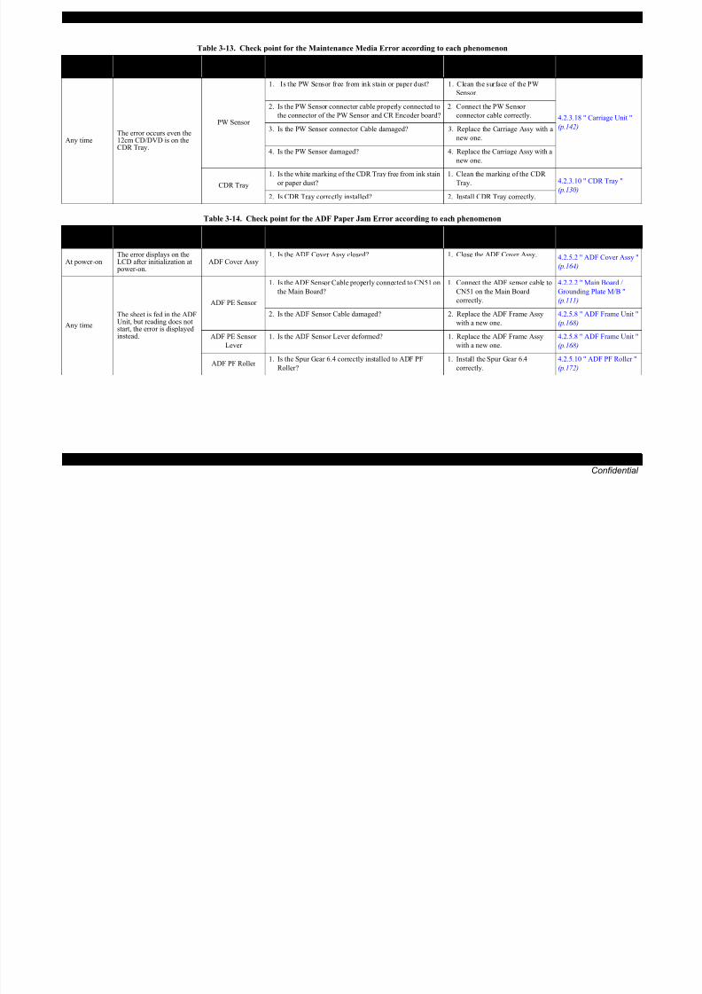
8/22/2019 TX 700 800
http://slidepdf.com/reader/full/tx-700-800 65/234
TROUBLESHOOTING Troubleshooting by Error Message 65
Confidential
Any timeThe error occurs even the12cm CD/DVD is on theCDR Tray.
PW Sensor
1. Is the PW Sensor free from ink stain or paper dust? 1. Clean the surface of the PW
Sensor.
4.2.3.18 " Carriage Unit "
(p.142)
2. Is the PW Sensor connector cable properly connected to
the connector of the PW Sensor and CR Encoder board?
2. Connect the PW Sensor
connector cable correctly.
3. Is the PW Sensor connector Cable damaged? 3. Replace the Carriage Assy with a
new one.
4. Is the PW Sensor damaged? 4. Replace the Carriage Assy with a
new one.
CDR Tray
1. Is the white marking of the CDR Tray free from ink stain
or paper dust?
1. Clean the marking of the CDR
Tray. 4.2.3.10 " CDR Tray "(p.130)
2. Is CDR Tray correctly installed? 2. Install CDR Tray correctly.
Table 3-14. Check point for the ADF Paper Jam Error according to each phenomenon
Occurrence
TimingSymptoms
Failed Part /
Part NameCheck Point Remedy Reference
At power-on
The error displays on the
LCD after initialization at power-on. ADF Cover Assy
1. Is the ADF Cover Assy closed? 1. Close the ADF Cover Assy. 4.2.5.2 " ADF Cover Assy "
(p.164)
Any time
The sheet is fed in the ADFUnit, but reading does notstart, the error is displayedinstead.
ADF PE Sensor
1. Is the ADF Sensor Cable properly connected to CN51 on
the Main Board?
1. Connect the ADF sensor cable to
CN51 on the Main Board
correctly.
4.2.2.2 " Main Board /
Grounding Plate M/B "
(p.111)
2. Is the ADF Sensor Cable damaged? 2. Replace the ADF Frame Assy
with a new one.
4.2.5.8 " ADF Frame Unit "
(p.168)
ADF PE Sensor
Lever
1. Is the ADF Sensor Lever deformed? 1. Replace the ADF Frame Assy
with a new one.
4.2.5.8 " ADF Frame Unit "
(p.168)
ADF PF Roller 1. Is the Spur Gear 6.4 correctly installed to ADF PF
Roller?
1. Install the Spur Gear 6.4
correctly.
4.2.5.10 " ADF PF Roller "
(p.172)
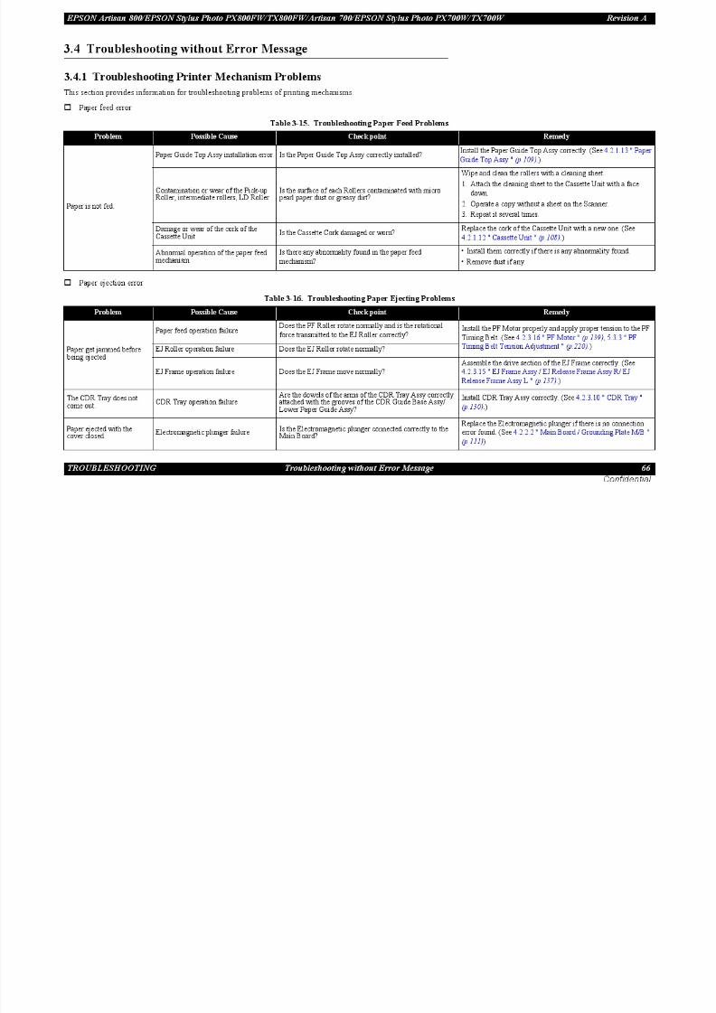
8/22/2019 TX 700 800
http://slidepdf.com/reader/full/tx-700-800 66/234

8/22/2019 TX 700 800
http://slidepdf.com/reader/full/tx-700-800 67/234
EPSON Artisan 800/EPSON Stylus Photo PX800FW/TX800FW/Artisan 700/EPSON Stylus Photo PX700W/TX700W Revision A
Contamination of the Printhead surface(dots are missing)
Run a cleaning and nozzle check. Repeat it several times. Clean the Printhead surface using a cotton-tipped swab.
Table 3-18. Troubleshooting Print Quality Problems
Problem Possible Cause Check point Remedy

8/22/2019 TX 700 800
http://slidepdf.com/reader/full/tx-700-800 68/234
TROUBLESHOOTING Troubleshooting without Error Message 68
Confidential
Dots are sometimes missing
(dots are missing)g p g pp
Ink cartridge failure Replace the ink cartridges with new ones, and run a nozzlecheck. Replace the Ink cartridges with new ones.
Poor connection of the Head FFCCheck the FFC using a tester. Does the result show
abnormality?
Replace the Head FFC with a new one. (See 4.2.3.1 " Printhead
(TBD) " (p.118), 4.2.3.18 " Carriage Unit " (p.142).)
Printhead failure Run a cleaning several times, and then run a nozzle check.If the cleaning does not solve the problem, replace the Printhead
with a new one. (See 4.2.3.1 " Printhead (TBD) " (p.118).)
Printout is totally abnormal
Poor connection of the Head FFCIs the FFC securely connected to the boards and Carriage
Assy?Connect the Head FFC correctly.
Printhead failure Is the Head FFC securely connected to the Printhead?If no problem is found in the connection, replace the Printhead
with a new one. (See 4.2.3.1 " Printhead (TBD) " (p.118).)
Vertical lines are notstraight
Improper Bi-D adjustment Has the Bi-D adjustment been carried out properly?Carry out the Bi-D adjustment. (See 5.2 " Adjustment by Using
Adjustment Program (TBD) " (p.204).)
EPSON Artisan 800/EPSON Stylus Photo PX800FW/TX800FW/Artisan 700/EPSON Stylus Photo PX700W/TX700W Revision A
Contamination of the CR shaft Is the CR shaft free from dirt? Clean the CR shaft surface with a soft dry cloth.
Table 3-18. Troubleshooting Print Quality Problems
Problem Possible Cause Check point Remedy

8/22/2019 TX 700 800
http://slidepdf.com/reader/full/tx-700-800 69/234
TROUBLESHOOTING Troubleshooting without Error Message 69
Confidential
White bands appear on printouts
Contamination of the CR Guide Plate Is the CR Guide Plate free from dirt? Clean the CR Guide Plate surface with a soft dry cloth.
PF Roller failure
Is the PF Roller free from dirt? Carefully clean the PF Roller surface with a soft brush.
Is the PF Roller damaged?Replace the PF Roller with a new one.
(See 4.2.3.1 " Printhead (TBD) " (p.118).)
Ink cartridge failureSet new ink cartridges and make a test print. The problem
does not occur?Replace the Ink cartridges with new ones.
Sliding operation failure of theCarriage
Is the backside of the Main Frame where the Carriage slides
against adequately lubricated?
Clean the Main Frame and apply G-71 grease as specified.
(See 6.1.3 " Lubrication " (p.224).)
Improper platen gap Is the platen gap setting correct? Carry out the PG adjustment.(See 5.3.1 " PG Adjustment (TBD) " (p.216).)
Damage of gearsAre the gears of the PF and ASF mechanisms free from
damage or deformation?Replace the faulty part with a new one.
Due to contamination on the Printheadsurface, ink droplets are fireddiagonally.
Run a cleaning and make a test print. Repeat it several
times.Clean the Printhead surface using a cotton-tipped swab.
Is the Head Cleaner free from dust or dirt?Clean the Head Cleaner or replace it with a new one.
(See 4.2.3.8 " Ink System " (p.127).)
Printhead failure Run a cleaning several times, and then make a test print.Replace the Printhead with a new one.
(See 4.2.3.1 " Printhead (TBD) " (p.118).)
CR Shaft failure
Is the CR shaft correctly installed?Reassemble the CR shaft.
(See 4.2.3.18 " Carriage Unit " (p.142).)
Is the CR shaft surface damaged?Replace the CR shaft with a new one.
(See 4.2.3.18 " Carriage Unit " (p.142).)
EPSON Artisan 800/EPSON Stylus Photo PX800FW/TX800FW/Artisan 700/EPSON Stylus Photo PX700W/TX700W Revision A
Ink is not supplied properly
Table 3-19. Troubleshooting Ink Supply Problems
Problem Possible Cause Check point Remedy

8/22/2019 TX 700 800
http://slidepdf.com/reader/full/tx-700-800 70/234
TROUBLESHOOTING Troubleshooting without Error Message 70
Confidential
The carriage movescorrectly, but the printout isabnormal
Ink cartridge failureSet new ink cartridges and make a test print. The problem
does not occur?Replace the Ink cartridges with new ones.
Incorrect connection of the Head FFCIs the Head FFC properly connected to the Printhead and
CN1, CN2, CN3 and CN4 connectors on the Main Board?
Connect the Head FFC correctly. (See 4.2.3.1 " Printhead (TBD)
" (p.118).)
Head Cleaner failure Is the Head Cleaner free from dust or dirt?Clean the Head Cleaner or replace it with a new one. (See
4.2.3.8 " Ink System " (p.127).)
Poor connection of the Head FFCCheck the FFC using a tester. Does the result show
abnormality?
Replace the Head FFC with a new one. (See 4.2.3.1 " Printhead
(TBD) " (p.118), 4.2.3.18 " Carriage Unit " (p.142).)
Printhead failure Run a cleaning and make a test print. Repeat it severaltimes.
If the cleaning does not solve the problem, replace the Printheadwith a new one. (See 4.2.3.1 " Printhead (TBD) " (p.118).)
Ink leak or clogging
Is ink leakage observed on the Printhead/Cartridge Box
Unit?
Install the ink cartridges correctly. If this does not solve the
problem, replace the ink cartridges with new ones.
Is the Ink Supply Tube Assy properly connected to the
Printhead and Cartridge Box Unit?
Connect Ink Supply Tube Assy to the Printhead and Cartridge
Box Unit correctly. If the problem is not solved, replace the
Printhead, or Ink Supply Tube Assy/Cartridge Box Unit with
new ones. (See 4.2.3.1 " Printhead (TBD) " (p.118), 4.2.3.7 " Ink
Supply IC Holder Assy " (p.125).)
Is the Decompression Tube properly connected to the
Cartridge Box Unit?
If no problem is found in the connection, replace the
Decompression Tube with a new one. (See 4.2.3.5 "
Decompression Pump Unit " (p.122).)
EPSON Artisan 800/EPSON Stylus Photo PX800FW/TX800FW/Artisan 700/EPSON Stylus Photo PX700W/TX700W Revision A
Waste ink error
Table 3-20. Troubleshooting Waste Ink Problems
Problem Possible Cause Check point Remedy
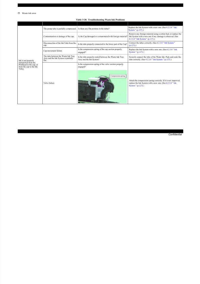
8/22/2019 TX 700 800
http://slidepdf.com/reader/full/tx-700-800 71/234
TROUBLESHOOTING Troubleshooting without Error Message 71
Confidential
Problem Possible Cause Check point Remedy
Ink is not properlytransported from thePrinthead to the cap, orfrom the cap to the InkTubes.
The pump tube is partially compressed. Is there any flat portions in the tubes? Replace the Ink System with a new one. (See 4.2.3.8 " InkSystem " (p.127).)
Contamination or damage of the cap. Is the Cap damaged or contaminated with foreign material?
Remove any foreign material using a cotton bud, or replace the
Ink System with a new one if any damage is observed. (See
4.2.3.8 " Ink System " (p.127).)
Disconnection of the Ink Tube from thecap.
Is the tube properly connected to the lower part of the Cap?Connect the tubes correctly. (See 4.2.3.8 " Ink System "
(p.127).)
Cap movement failureIs the compression spring of the cap section properly
engaged?
Replace the Ink System with a new one. (See 4.2.3.8 " Ink
System " (p.127).)
The tube between the Waste Ink TrayAssy and the Ink System is partiallyflat.
Is the tube properly routed between the Waste Ink Tray
Assy and the Ink System?
Securely connect the tube of the Waste Ink Pads and route the
tube correctly. (See 4.2.3.8 " Ink System " (p.127).)
Valve failure
Is the compression spring of the valve section properly
engaged?
Attach the compression spring correctly. If it is not improved,
replace the Ink System with a new one. (See 4.2.3.8 " Ink
System " (p.127).)
Compression spring
EPSON Artisan 800/EPSON Stylus Photo PX800FW/TX800FW/Artisan 700/EPSON Stylus Photo PX700W/TX700W Revision A
3.4.2 Troubleshooting Electrical Problems
Check the points described in the table below when the printer does not operate at all (LED does not light) at power-on.
Table 3-21. Troubleshooting Power Supply Problems

8/22/2019 TX 700 800
http://slidepdf.com/reader/full/tx-700-800 72/234
TROUBLESHOOTING Troubleshooting without Error Message 72
Confidential
3.4.3 Troubleshooting I/F-related Problems
This section provides information for troubleshooting problems related to the USB interfaces and the Memory Card Slot.
USB Interface Error
Problem Check Point Remedy
Power code failureReplace the power code with another one, and check
whether the printer is normally powered or not.Replace the power code with a new one.
Incorrect AC power supplyDoes the AC power source match with the requirement of
the printer?Use the correct power source.
Poor connection of the connectorsIs the Power Supply Unit Cable properly connected to
CN501 connector on the Main Board?Connect the cable correctly.
The fuse is blown Is the fuse (F1) on the Power Supply Board blown? Replace the Power Supply Board.
Abnormal output of the Power Supply BoardIs a normal voltage being output from the Power Supply
Board?
Replace the Main Board when the output voltage is normal.
Replace the Power Supply Unit when the output voltage is
abnormal.
Table 3-22. USB I/F Error
Problem Check Point Remedy
Incorrect printer driver installation
Click My Computer - Property - Device Manager on
Windows computer. Is the printer driver is included in the
Other Devices by mistake?
Uninstall the driver and reinstall it correctly referring to the
Users Guide.
USB cable failureReplace the cable with another one. Does the problem still
occur?Replace the USB cable.
Poor connection Is the USB terminal free from foreign materials? Remove the foreign material, and clean the contact points.
Main board failure Check the Main Board for any damage. Replace the Main Board.
Card board failure Check the STG Board for any damage. Replace the STG Board.
EPSON Artisan 800/EPSON Stylus Photo PX800FW/TX800FW/Artisan 700/EPSON Stylus Photo PX700W/TX700W Revision A
Troubleshooting Memory Card-related Problems
Table 3-23. Troubleshooting Memory Card-related problems
Problem Check Point Remedy

8/22/2019 TX 700 800
http://slidepdf.com/reader/full/tx-700-800 73/234
TROUBLESHOOTING Troubleshooting without Error Message 73
Confidential
Memory Card data damageIs the data on the memory card damaged by static electricity
or the like?
Check if the card is readable with the computer. If not, format
the card.
Use unsupported Memory Card Check if the card is supported. Use a supported memory card.
Memory card failure Check if another Memory Card is recognized. Replace the Memory Card with a new one.
Poor connection
Are the memory card or the slot free from foreign
materials?Remove the foreign material, and clean the contact points.
Is the slot pin cracked or deformed? Replace the Card Board.
Firmware error --- Update the firmware.
Memory card can not be ejectedIs the memory card inserted without the memory card
adapter?
Turn the power off and remove the memory card with the
tweezers.
Electrical noise Are the positions of the FFC and ferrite core appropriate?Replace the Main Board with a new one if there is no problem
with the routing.
Main board failure Check the Main Board for any damage. Replace the Main Board with a new one.
Card board failure Check the STG Board for any damage. Replace the STG Board.
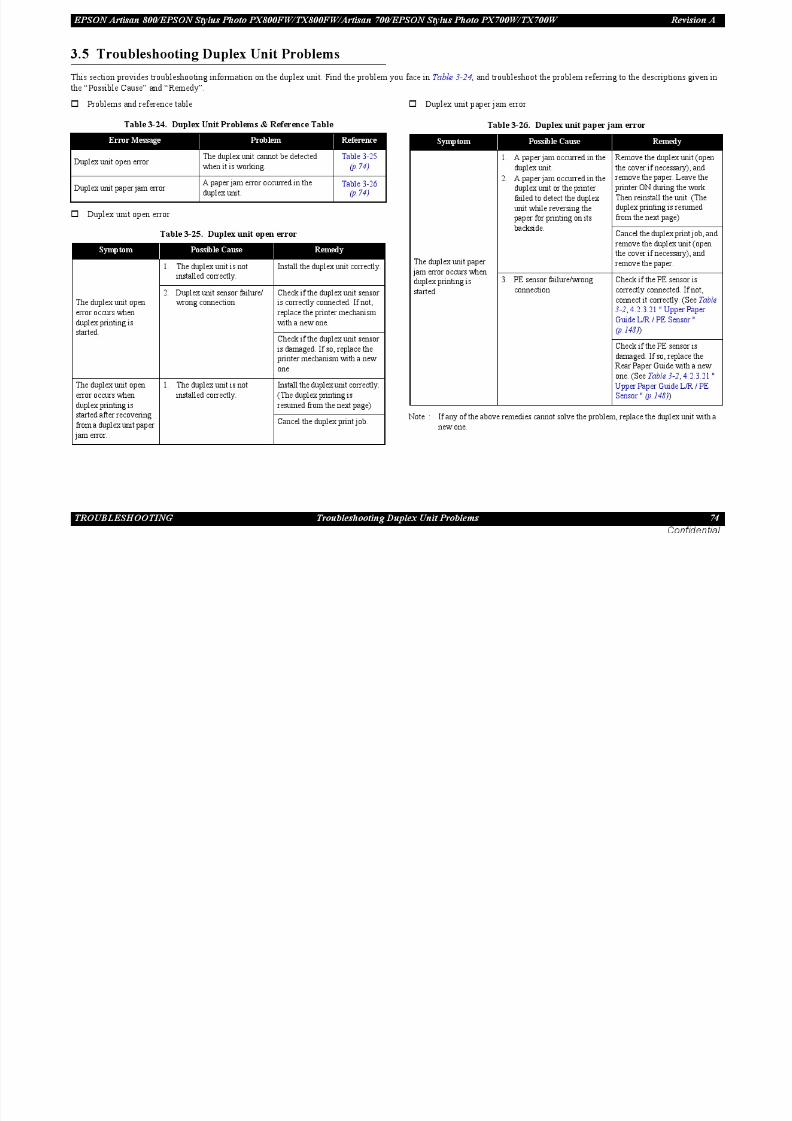
8/22/2019 TX 700 800
http://slidepdf.com/reader/full/tx-700-800 74/234

8/22/2019 TX 700 800
http://slidepdf.com/reader/full/tx-700-800 75/234
EPSON Artisan 800/EPSON Stylus Photo PX800FW/TX800FW/Artisan 700/EPSON Stylus Photo PX700W/TX700W Revision A
Troubles during printing and scanning from PC
Table 3-29. Troubles during printing and scanning from PC
Symptom Check Point Remedy
Print cannot be made 1 In Wireless LAN’s case check Correctly connect the

8/22/2019 TX 700 800
http://slidepdf.com/reader/full/tx-700-800 76/234
TROUBLESHOOTING Network Troubleshooting 76
Confidential
Print cannot be made
Scan cannot be made
1. In Wireless LAN s case, check
if the network connection between the PC and Access
Point is made.
Correctly connect the
computer and the AccessPoint.
2. In Wired LAN’s case, check if
the computer and the printer are
properly connected to a LAN
port such as a hub or router.
Correctly connect the
computer and the printer to a
LAN port such as a hub or
router using a LAN cable.
3. Check the status of network
settings/connection by printing
the network status sheet.
Correctly set the network
connection again if the
network connection is notmade.
4. Check if the link lamp on the
Access Point or hub connected
to the printer is lighting or
flashing.
• Try using another port.
• Replace the LAN cable.
• Configure Wireless LAN
setting correctly.
5. Check if the network settings
are correctly configured?
Correctly configure the
network settings.
6. Check if the network setting
screen is displayed on the
Control Panel.
Close the screen.
EPSON Scan cannot
be started
1. For EPSON Scan settings,
check if IP address is set
directly.
If IP address is set using the
DHCP function, specify IP
address by searching address.

8/22/2019 TX 700 800
http://slidepdf.com/reader/full/tx-700-800 77/234

8/22/2019 TX 700 800
http://slidepdf.com/reader/full/tx-700-800 78/234

8/22/2019 TX 700 800
http://slidepdf.com/reader/full/tx-700-800 79/234
EPSON Artisan 800/EPSON Stylus Photo PX800FW/TX800FW/Artisan 700/EPSON Stylus Photo PX700W/TX700W Revision A
PPS-MPS BE 4E Partial Page Signal-MultiPage Signal
Table 3-33. Command/Response Code
Command/
response code
FCF value (HEX)
(LSB first: X=0) Content
First Second
PIX FF - PIXel image
Table 3-33. Command/Response Code
Command/
response code
FCF value (HEX)
(LSB first: X=0) Content
First Second

8/22/2019 TX 700 800
http://slidepdf.com/reader/full/tx-700-800 80/234
TROUBLESHOOTING FAX Troubleshooting (EPSON Artisan 800/EPSON Stylus Photo PX800FW/TX800FW only) 80
Confidential
g g g g
PPS-EOP BE 2E Partial Page Signal-End Of Procedure
PPS-PRI-EOM BE 9EPartial Page Signal-Procedure Interrupt-
End Of Message
PPS-PRI-MPS BE 5EPartial Page Signal-Procedure Interrupt-
MultiPage Signal
PPS-PRI-EOP BE 3EPartial Page Signal-Procedure Interrupt-
End Of Procedure
PPS-EOS BE 1E Partial Page Signal-End Of Selection
PPS-NULL BE 00 Partial Page Signal-partial page boundary
EOR-EOM CE 8E End Of Retransmission-End Of Message
EOR-MPS CE 4E End Of Retransmission-MultiPage Signal
EOR-EOP CE 2E End Of Retransmission-End Of Procedure
EOR-PRI-EOM CE 9EEnd Of Retransmission-Procedure
Interrupt-End Of Message
EOR-PRI-MPS CE 5EEnd Of Retransmission-Procedure
Interrupt-MultiPage Signal
EOR-PRI-EOP CE 3EEnd Of Retransmission-Procedure
Interrupt-End Of ProcedureEOR-EOS CE 1E End Of Retransmission-End Of Selection
EOR-NULL CE 00End Of Retransmission- partial page
boundary
RR 6E - Receive Ready
MCF 8C - Message ConFirmation
RTP CC - ReTrain Positive
RTN 4C - ReTrain Negative
PIP AC - Procedure Interrupt Positive
PIN 2C - Procedure Interrupt Negative
PPR BC - Partial Page Request
RNR EC - Receive Not Ready
ERR 1C - Response for End of Retransmission
Reserved (FDM) FC - File Diagnostic Message
DCN FA - DisCoNnect
CRP 1A - Command RePeat
Reserved (FNV) CA - Field Not Valid
g
Space Other combinations Unknown command/response

8/22/2019 TX 700 800
http://slidepdf.com/reader/full/tx-700-800 81/234
EPSON Artisan 800/EPSON Stylus Photo PX800FW/TX800FW/Artisan 700/EPSON Stylus Photo PX700W/TX700W Revision A
Cannot dial
The telephone cable is not connected properly. Connect the telephone cable properly.
The telephone line is not working. Verify if the phone line works by connecting to a phone to it.
Pulse/Tone dial setting error Turn the setting to the other one and try again
Table 3-34. Troubleshooting based on the error code/superficial phenomenon
Error code (LCD Message)/Phenomenon Description Remedy

8/22/2019 TX 700 800
http://slidepdf.com/reader/full/tx-700-800 82/234
TROUBLESHOOTING FAX Troubleshooting (EPSON Artisan 800/EPSON Stylus Photo PX800FW/TX800FW only) 82
Confidential
Pulse/Tone dial setting error Turn the setting to the other one and try again.
Cannot receive/send faxes in color ECM is set to off. Set to on and try again.
Fax mode is set to “B&W only”. Set to “B&W/Color”.
Cannot print all the received data when printing
data stored in memory
The size of the memory is 2.0 Mbyte. If the data
becomes over the set threshold, oldest data are deleted
to make room for new ones.
Ask the sender to resend the data if necessary because the data deleted from the memory can
not be restored.
Images run off the paper
Auto reduction is set to off. Set auto reduction to on and reprint the data.
Paper size setting does not match the size of the
received data.
Choose the correct setting and reprint the data.
Paper size setting does not match the size of papers in
the tray.Choose the correct setting or load correct sized papers in the tray and reprint the data.
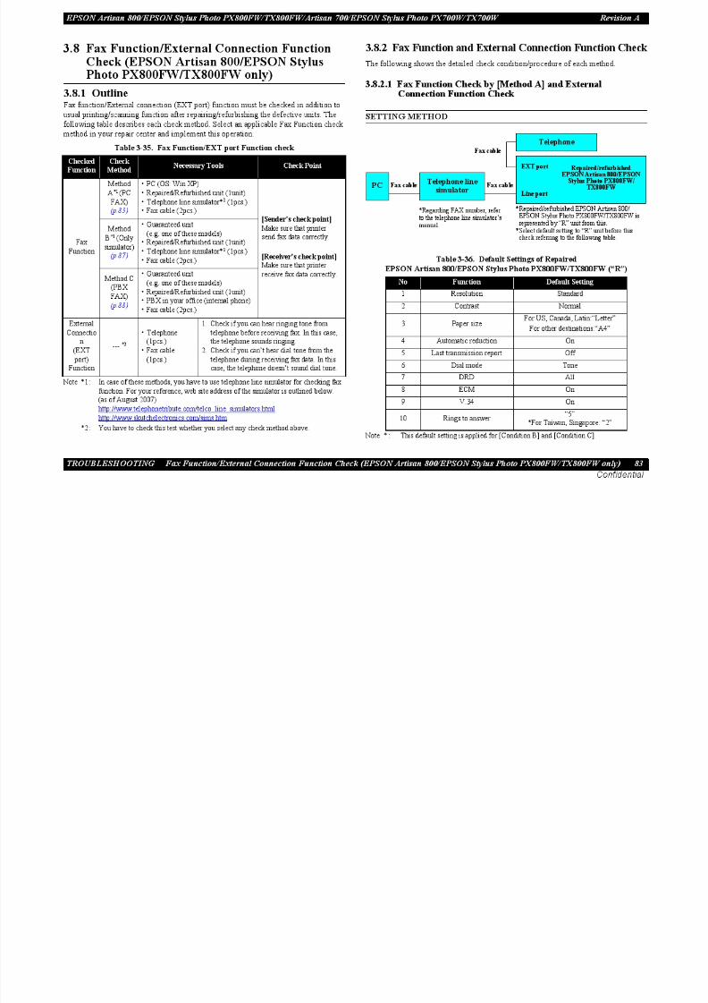
8/22/2019 TX 700 800
http://slidepdf.com/reader/full/tx-700-800 83/234
EPSON Artisan 800/EPSON Stylus Photo PX800FW/TX800FW/Artisan 700/EPSON Stylus Photo PX700W/TX700W Revision A
CHECK PROCEDURE
[Sender: PC =>Receiver: “R” unit]
1. Install test chart (test chart name: “ITUT#1LTR.pdf”) to PC.
2. Open test chart and select “File” menu.
3. Select “Print.....”.

8/22/2019 TX 700 800
http://slidepdf.com/reader/full/tx-700-800 84/234
TROUBLESHOOTING Fax Function/External Connection Function Check (EPSON Artisan 800/EPSON Stylus Photo PX800FW/TX800FW only) 84
Confidential
4. Select “Fax” from “Printer Name”.
EPSON Artisan 800/EPSON Stylus Photo PX800FW/TX800FW/Artisan 700/EPSON Stylus Photo PX700W/TX700W Revision A
5. Input “Receiver Name” and “Fax Number”, and click “Next” button. 7. Check as below screen, and click “Next” button.
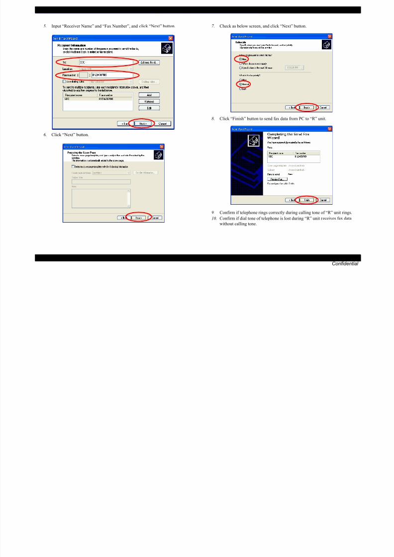
8/22/2019 TX 700 800
http://slidepdf.com/reader/full/tx-700-800 85/234
TROUBLESHOOTING Fax Function/External Connection Function Check (EPSON Artisan 800/EPSON Stylus Photo PX800FW/TX800FW only) 85
Confidential
6. Click “Next” button.
8. Click “Finish” button to send fax data from PC to “R” unit.
9. Confirm if telephone rings correctly during calling tone of “R” unit rings.
10. Confirm if dial tone of telephone is lost during “R” unit receives fax data
without calling tone.
EPSON Artisan 800/EPSON Stylus Photo PX800FW/TX800FW/Artisan 700/EPSON Stylus Photo PX700W/TX700W Revision A
[Sender: “R” unit => Receiver: PC]
1. Select “Printer and Faxes” from Windows start menu.
3. Select “Receiver a fax now.....” from file menu.

8/22/2019 TX 700 800
http://slidepdf.com/reader/full/tx-700-800 86/234
TROUBLESHOOTING Fax Function/External Connection Function Check (EPSON Artisan 800/EPSON Stylus Photo PX800FW/TX800FW only) 86
Confidential
2. Select “Fax console” window.
4. Set test chart on the document glass of “R” unit.

8/22/2019 TX 700 800
http://slidepdf.com/reader/full/tx-700-800 87/234
EPSON Artisan 800/EPSON Stylus Photo PX800FW/TX800FW/Artisan 700/EPSON Stylus Photo PX700W/TX700W Revision A
3.8.2.3 Fax Function Check by [Method C] and ExternalConnection Function Check
SETTING METHOD
[Sender: “G” unit => Receiver: “R” unit]
1. Set test chart on the document glass of “G” unit.
2. Enter fax mode by pushing fax button.
3. Input fax number of “R” unit on “G” unit. (Regarding FAX number, refer to
the telephone line simulator’s manual.)
4 P h “St t” b tt i “B&W” dPBX
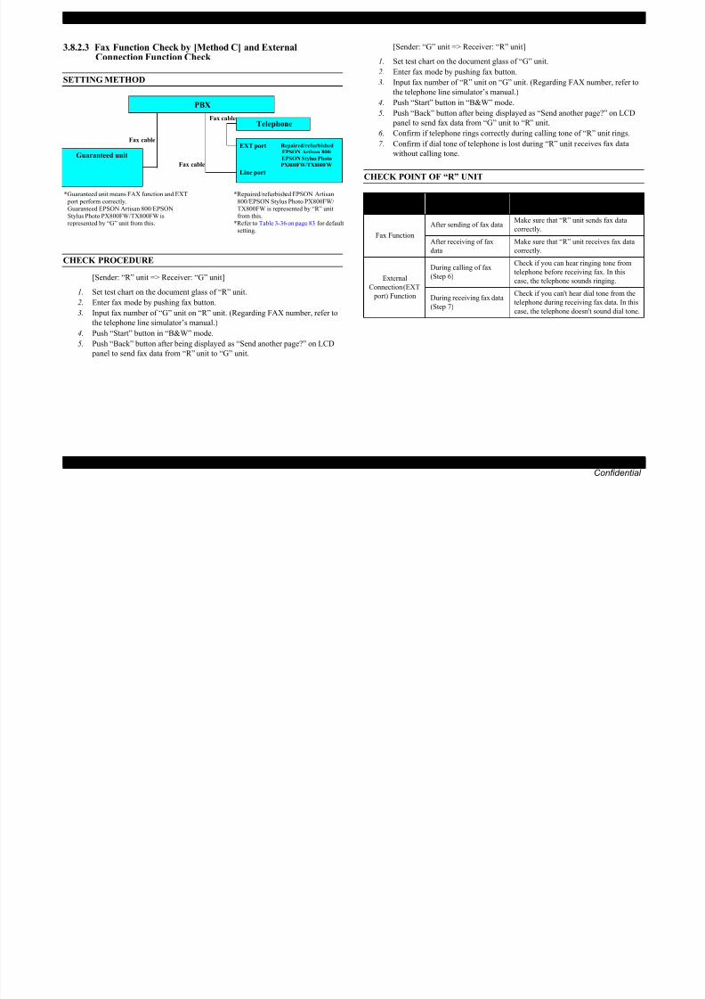
8/22/2019 TX 700 800
http://slidepdf.com/reader/full/tx-700-800 88/234
TROUBLESHOOTING Fax Function/External Connection Function Check (EPSON Artisan 800/EPSON Stylus Photo PX800FW/TX800FW only) 88
Confidential
CHECK PROCEDURE
[Sender: “R” unit => Receiver: “G” unit]
1. Set test chart on the document glass of “R” unit.
2. Enter fax mode by pushing fax button.
3. Input fax number of “G” unit on “R” unit. (Regarding FAX number, refer to
the telephone line simulator’s manual.)
4. Push “Start” button in “B&W” mode.
5. Push “Back” button after being displayed as “Send another page?” on LCD
panel to send fax data from “R” unit to “G” unit.
4. Push “Start” button in “B&W” mode.5. Push “Back” button after being displayed as “Send another page?” on LCD
panel to send fax data from “G” unit to “R” unit.
6. Confirm if telephone rings correctly during calling tone of “R” unit rings.
7. Confirm if dial tone of telephone is lost during “R” unit receives fax data
without calling tone.
CHECK POINT OF “R” UNIT
Telephone
EXT port
Line port
Repaired/refurbished
EPSON Artisan 800/
EPSON Stylus Photo
PX800FW/TX800FW
Fax cable
Fax cable
Fax cable
*Repaired/refurbished EPSON Artisan800/EPSON Stylus Photo PX800FW/TX800FW is represented by “R” unitfrom this.
*Refer to Table 3-36 on page 83 for defaultsetting.
*Guaranteed unit means FAX function and EXT port perform correctly. Guaranteed EPSON Artisan 800/EPSONStylus Photo PX800FW/TX800FW isrepresented by “G” unit from this.
PBX
Guaranteed unit
Checked
FunctionCheck Timing Check Point
Fax Function
After sending of fax dataMake sure that “R” unit sends fax data
correctly.
After receiving of fax
data
Make sure that “R” unit receives fax data
correctly.
External
Connection (EXT
port) Function
During calling of fax
(Step 6)
Check if you can hear ringing tone from
telephone before receiving fax. In thiscase, the telephone sounds ringing.
During receiving fax data
(Step 7)
Check if you can't hear dial tone from the
telephone during receiving fax data. In this
case, the telephone doesn't sound dial tone.

8/22/2019 TX 700 800
http://slidepdf.com/reader/full/tx-700-800 89/234
Confidential
C H A P T E R
4DISASSEMBLY/ASSEMBLY

8/22/2019 TX 700 800
http://slidepdf.com/reader/full/tx-700-800 90/234
EPSON Artisan 800/EPSON Stylus Photo PX800FW/TX800FW/Artisan 700/EPSON Stylus Photo PX700W/TX700W Revision A
4.1.2 Tools
Use only specified tools to avoid damaging the printer.
4.1.3 Work Completion Check
If any service is made to the printer, use the checklist shown below to confirm all
works are completed properly and the printer is ready to be returned to the user.Table 4-1. Tools
Name EPSON Tool Code*
(+) Phillips screwdriver #1 1080530
Table 4-2. Work Completion Check
Classification Item Check Point Status
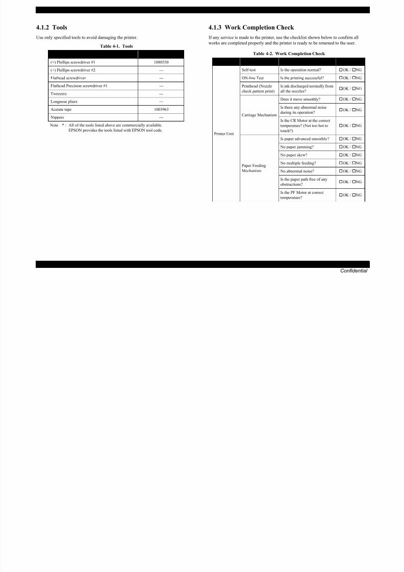
8/22/2019 TX 700 800
http://slidepdf.com/reader/full/tx-700-800 91/234
DISASSEMBLY/ASSEMBLY Overview 91
Confidential
Note * : All of the tools listed above are commercially available.
EPSON provides the tools listed with EPSON tool code.
(+) Phillips screwdriver #1 1080530
(+) Phillips screwdriver #2 ---
Flathead screwdriver ---
Flathead Precision screwdriver #1 ---
Tweezers ---
Longnose pliers ---
Acetate tape 1003963
Nippers ---
Classification Item Check Point Status
Printer Unit
Self-test Is the operation normal? OK / NG
ON-line Test Is the printing successful? OK / NG
Printhead (Nozzle
check pattern print)
Is ink discharged normally from
all the nozzles? OK / NG
Carriage Mechanism
Does it move smoothly? OK / NG
Is there any abnormal noiseduring its operation?
OK / NG
Is the CR Motor at the correct
temperature? (Not too hot to
touch?)
OK / NG
Paper Feeding
Mechanism
Is paper advanced smoothly? OK / NG
No paper jamming? OK / NG
No paper skew? OK / NG
No multiple feeding? OK / NG
No abnormal noise? OK / NG
Is the paper path free of any
obstructions? OK / NG
Is the PF Motor at correct
temperature? OK / NG
EPSON Artisan 800/EPSON Stylus Photo PX800FW/TX800FW/Artisan 700/EPSON Stylus Photo PX700W/TX700W Revision A
Mechanism
Is glass surface dirty? OK / NG
Is any foreign substance mixed
in the CR movement area? OK / NG
Table 4-2. Work Completion Check
Classification Item Check Point Status

8/22/2019 TX 700 800
http://slidepdf.com/reader/full/tx-700-800 92/234
DISASSEMBLY/ASSEMBLY Overview 92
Confidential
Scanner unit CR mechanism
Does CR operate smoothly? OK / NG
Does CR operate together with
scanner unit? OK / NG
Does CR make abnormal noise
during its operation? OK / NG
LED
Does LED turn on normally?
And is white reflection test done
near home position?
OK / NG
ON-line Test ON-line Test Is the operation normal? OK / NG
Copy Copy Is the local copy action normal? OK / NG
AdjustmentSpecified
Adjustment
Are all the adjustment done
correctly OK / NG
LubricationSpecified
Lubrication
Are all the lubrication made at
the specified points?OK / NG
Is the amount of lubrication
correct? OK / NG
Function ROM Version Version: OK / NG
Packing
Ink CartridgeAre the ink cartridges installed
correctly? OK / NG
Waste Ink padAre the waste ink pads adequate
to absorb? OK / NG
Protective materialsIs the printer carriage placed at
the capping position? OK / NG
OthersAttachments,
Accessories
Have all the relevant items been
included in the package? OK / NG
EPSON Artisan 800/EPSON Stylus Photo PX800FW/TX800FW/Artisan 700/EPSON Stylus Photo PX700W/TX700W Revision A
4.1.4 Additional Procedure/Procedural Differences
The disassembly/reassembly procedures of EPSON Artisan800/EPSON Stylus Photo PX800FW/EPSON Stylus Photo TX800FW and EPSON Artisan700/EPSON Stylus Photo
PX700W/EPSON Stylus Photo TX700W are different. Unless otherwise specified, this chapter describes EPSON Artisan800/EPSON Stylus Photo PX800FW/EPSON Stylus Photo
TX800FW. Refer to the pages mentioned below for the disassembly/reassembly procedures of EPSON Artisan700/EPSON Stylus Photo PX700W/EPSON Stylus Photo TX700W.
Each model is hereinafter called as follows. EPSON Artisan800/EPSON Stylus Photo PX800FW/EPSON Stylus Photo TX800FW: Artisan 800/PX800FW/TX800FW

8/22/2019 TX 700 800
http://slidepdf.com/reader/full/tx-700-800 93/234
DISASSEMBLY/ASSEMBLY Overview 93
Confidential
EPSON Artisan800/EPSON Stylus Photo PX800FW/EPSON Stylus Photo TX800FW: Artisan 800/PX800FW/TX800FW
EPSON Artisan700/EPSON Stylus Photo PX700W/EPSON Stylus Photo TX700W: Artisan 700/PX700W/TX700W
Table 4-3. Procedure Differences
Parts name Reference pageArtisan 800/PX800FW/TX800FW Artisan 700/PX700W/TX700W
ADF Unit ADF mechanism No ADF mechanism Artisan 800/PX800FW/TX800FW
4.2.1.1 " ADF Unit (Artisan 800/
PX800FW/TX800FW only) " (p.97)
Scanner Unit
The Document Cover and Housing are different depend on the ADF mechanism or not.
Artisan 800/PX800FW/TX800FW
4.2.5 " Disassembly of the ADF Unit
(Artisan 800/PX800FW/TX800FW only) "
(p.163)
4.2.4 " Disassembling Scanner Unit "
(p.156)
Artisan 700/PX700W/TX700W
4.3.3.1 " Document Cover " (p.187)
4.3.3.2 " Scanner Upper Housing (Artisan
700/PX700W/TX700W) " (p.188)
Panel Unit7.8 inch touch panel
3.5 inch LCD
2.5 inch LCD
(no touch panel)
Artisan 800/PX800FW/TX800FW
4.2.2.1 " Panel Unit " (p.109)
Artisan 700/PX700W/TX700W
4.3.2.1 " Panel Unit (Artisan 700/PX700W/
TX700W) " (p.181)
ADF Unit DocumentCover
EPSON Artisan 800/EPSON Stylus Photo PX800FW/TX800FW/Artisan 700/EPSON Stylus Photo PX700W/TX700W Revision A
Upper Housing
Housing is different.
The numbers of the screws and positions are partially different.
Table 4-3. Procedure Differences
Parts name Reference pageArtisan 800/PX800FW/TX800FW Artisan 700/PX700W/TX700W
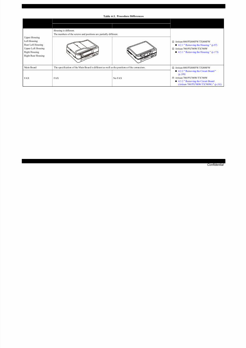
8/22/2019 TX 700 800
http://slidepdf.com/reader/full/tx-700-800 94/234
DISASSEMBLY/ASSEMBLY Overview 94
Confidential
Left Housing
Rear Left Housing
Upper Left Housing
Right Housing
Right Rear Housing
Artisan 800/PX800FW/TX800FW
4.2.1 " Removing the Housing " (p.97)
Artisan 700/PX700W/TX700W
4.3.1 " Removing the Housing " (p.173)
Main Board The specification of the Main Board is different as well as the positions of the connectors. Artisan 800/PX800FW/TX800FW
4.2.2 " Removing the Circuit Board "
(p.109)
Artisan 700/PX700W/TX700W
4.3.2 " Removing the Circuit Board
(Artisan 700/PX700W/TX700W) " (p.181)
FAX FAX No FAX

8/22/2019 TX 700 800
http://slidepdf.com/reader/full/tx-700-800 95/234
EPSON Artisan 800/EPSON Stylus Photo PX800FW/TX800FW/Artisan 700/EPSON Stylus Photo PX700W/TX700W Revision A
“ 4.2.3.13 Main Frame ”(p134)
Flowchart 4-1 Disassembling Flowchart (1) (p95)
“ 4.2.3.1 Printhead (TBD) ”“ 4.2.3.14 Front Frame ”
(p136)
“ 4.2.3.16 PF Motor ”
(p139)
“ 4.2.3.17 CR Motor ”
(p140)
“ 4.2.5.2 ADF Cover Assy ”(p164)
Disassembling the ADF Unit (Artisan 800/PX800FW/TX800FW only)
“ 4.2.5.1 ADF Hinge ” (p163)
START
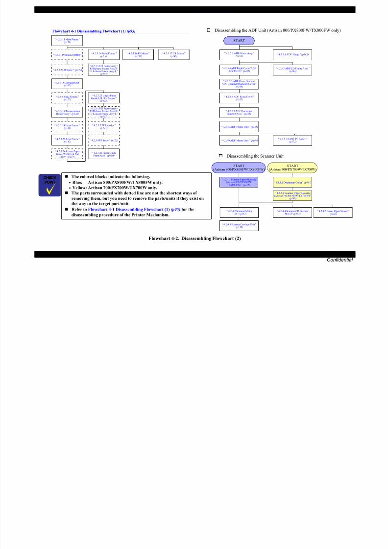
8/22/2019 TX 700 800
http://slidepdf.com/reader/full/tx-700-800 96/234
DISASSEMBLY/ASSEMBLY Disassembly Procedures 96
Confidential
Flowchart 4-2. Disassembling Flowchart (2)
The colored blocks indicate the following.
• Blue: Artisan 800/PX800FW/TX800FW only.
• Yellow: Artisan 700/PX700W/TX700W only.
The parts surrounded with dotted line are not the shortest ways of
removing them, but you need to remove the parts/units if they exist on
the way to the target part/unit.
Refer to Flowchart 4-1 Disassembling Flowchart (1) (p95) for the
disassembling procedure of the Printer Mechanism.
“ 4.2.3.18 Carriage Unit ”(p142)
“ 4.2.3.2 CR Scale ” (p120)
“ 4.2.3.8 Ink System ”(p127)
“ 4.2.3.19 TransmissionHolder Assy ” (p146)
“ 4.2.3.14 Front Frame ”(p136)
“ 4.2.3.20 Rear Frame ”(p147)
“ 4.2.3.24 Lower PaperGuide Waste Ink Pad
Assy ” (p154)
“ 4.2.3.21 Upper PaperGuide L/R / PE Sensor ”
(p148)
“ 4.2.3.3 PF Encoder ”(p121)
“ 4.2.3.4 PF Scale ” (p122)
“ 4.2.3.22 Paper GuideFront Assy ” (p150)
“ 4.2.3.15 EJ Frame Assy /EJ Release Frame Assy R/EJ Release Frame Assy L ”
(p137)
Disassembling the Scanner Unit
START(Artisan 700/PX700W/TX700W)
“ 4.2.4.1 Scanner Upper Housing(Artisan 800/PX800FW/
TX800FW) ” (p156)
“ 4.2.4.2 Scanner MotorUnit ” (p157)
“ 4.2.4.3 Scanner Carriage Unit ”(p158)
“ 4.3.3.1 Document Cover ” (p187)
“ 4.3.3.2 Scanner Upper Housing
(Artisan 700/PX700W/TX700W) ”(p188)
“ 4.2.4.5 Cover Open Sensor ”(p162)
“ 4.2.5.9 ADF Motor Unit ” (p169)“ 4.2.5.10 ADF PF Roller ”
(p172)
“ 4.2.5.8 ADF Frame Unit ” (p168)
“ 4.2.5.7 ADF DocumentSupport Assy ” (p168)
“ 4.2.5.6 ADF Front Cover ”(p167)
“ 4.2.5.5 ADF Cover Stacker/ADF Document Support Cover ”
(p166)
“ 4.2.5.4 ADF Right Cover/ADFRear Cover ” (p165)
“ 4.2.4.4 Scanner CR EncoderBoard ” (p161)
“ 4.2.5.3 ADF LD Frame Assy ”(p164)
“ 4.2.3.15 EJ Frame Assy /EJ Release Frame Assy R/EJ Release Frame Assy L ”
(p137)
START(Artisan 800/PX800FW/TX800FW)
EPSON Artisan 800/EPSON Stylus Photo PX800FW/TX800FW/Artisan 700/EPSON Stylus Photo PX700W/TX700W Revision A
4.2.1 Removing the Housing
4.2.1.1 ADF Unit (Artisan 800/PX800FW/TX800FW only)
Parts/Components need to be removed in advance:
None
Removal procedure
4. Disconnect the ADF Motor Cable and ADF Sensor Cable from the connectors
on the Main Board. (See Fig. 4-3.)
5. Pull out the terminal of the Grounding Wire from the fixing rib of the frame.
Grounding Wire
ADF Motor Cable

8/22/2019 TX 700 800
http://slidepdf.com/reader/full/tx-700-800 97/234
DISASSEMBLY/ASSEMBLY Disassembly Procedures 97
Confidential
1. Open the Scanner Unit.
2. Cut the fastener with a nipper as shown in Fig. 4-2 and remove the fastener.
3. Slide the Cable Cover to the rear of the printer by pushing the point A of the
Cable Cover to release the hooks (x4) and ribs (x2), and remove the Cable
Cover.
Figure 4-2. Removing the Cable Cover
Figure 4-3. Removing the ADF Unit (1)
The fastener needs to be cut when removing, and cannot be reused.
When installing the Cable Cover, replace it with a new one.
Figure 4-1. Damaged stopper
Fastener before cut Fastener after cut
Fastener
Cable Cover
Right side
Point A
Fastener
Cutting position
Cross-section
Hook
Rib
Terminal of GroundingWire and the fixing rib
Main Board
ADF Sensor Cable
EPSON Artisan 800/EPSON Stylus Photo PX800FW/TX800FW/Artisan 700/EPSON Stylus Photo PX700W/TX700W Revision A
6. Release the hooks (x2) of the Hinge and hook (x1) of the ADF Cable Coverfrom the rear side while holding the center of the ADF Unit (See Fig 4-4 )
4.2.1.2 Scanner Unit Take care not to let the cables get caught by the housing of the
Scanner Unit.
The disassembly/reassembly procedures of Artisan 700/PX700W/
TX700W differ from those of Artisan 800/PX800FW/TX800FW.
See 4.3.1.1 Scanner Unit (Artisan 700/PX700W/TX700W) (p173)
for the procedures.
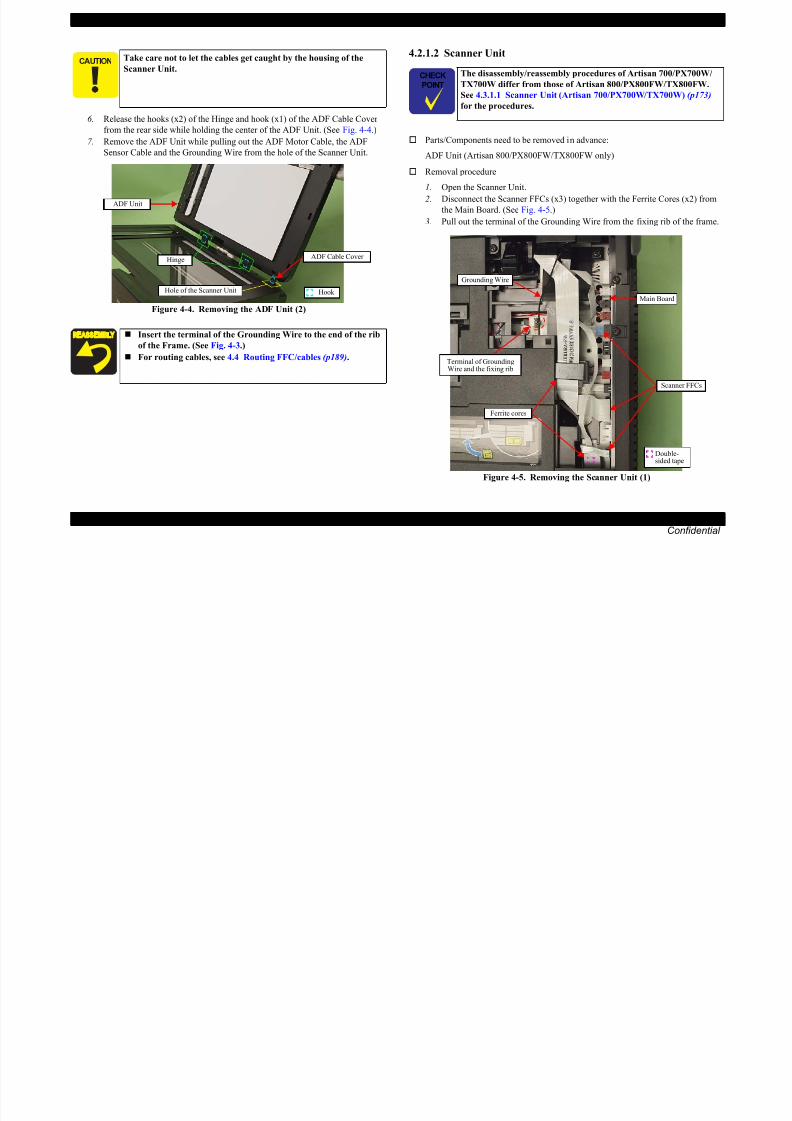
8/22/2019 TX 700 800
http://slidepdf.com/reader/full/tx-700-800 98/234
DISASSEMBLY/ASSEMBLY Disassembly Procedures 98
Confidential
from the rear side while holding the center of the ADF Unit. (See Fig. 4-4.)
7. Remove the ADF Unit while pulling out the ADF Motor Cable, the ADF
Sensor Cable and the Grounding Wire from the hole of the Scanner Unit.
Figure 4-4. Removing the ADF Unit (2)
Parts/Components need to be removed in advance:
ADF Unit (Artisan 800/PX800FW/TX800FW only)
Removal procedure
1. Open the Scanner Unit.
2. Disconnect the Scanner FFCs (x3) together with the Ferrite Cores (x2) from
the Main Board. (See Fig. 4-5.)3. Pull out the terminal of the Grounding Wire from the fixing rib of the frame.
Figure 4-5. Removing the Scanner Unit (1)
Insert the terminal of the Grounding Wire to the end of the rib
of the Frame. (See Fig. 4-3.)
For routing cables, see 4.4 Routing FFC/cables (p189).
Hook
ADF Unit
Hole of the Scanner Unit
Hinge ADF Cable Cover
Grounding Wire
Scanner FFCs
Ferrite cores
Double-sided tape
Main Board
Terminal of GroundingWire and the fixing rib
EPSON Artisan 800/EPSON Stylus Photo PX800FW/TX800FW/Artisan 700/EPSON Stylus Photo PX700W/TX700W Revision A
4. Remove the screw (x1) that secures the Scanner Unit.
Do not open/close the Scanner Unit with the screws removed to
avoid damage of the Scanner Unit Hinge.
When installing the Scanner Unit, follow the procedure below.
1. Align and insert the dowel of the Scanner Unit to the
positioning hole of the printer (Left inside).
2. Align and insert the rib of the Scanner Unit to the groove of
the Hinge.
Left Right
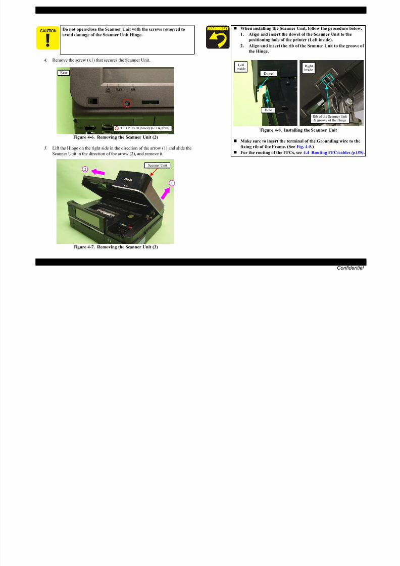
8/22/2019 TX 700 800
http://slidepdf.com/reader/full/tx-700-800 99/234
DISASSEMBLY/ASSEMBLY Disassembly Procedures 99
Confidential
Figure 4-6. Removing the Scanner Unit (2)
5. Lift the Hinge on the right side in the direction of the arrow (1) and slide the
Scanner Unit in the direction of the arrow (2), and remove it.
Figure 4-7. Removing the Scanner Unit (3)
Rear
C.B.P. 3x10 (black) (6±1Kgfcm)
Scanner Unit
1
2
Figure 4-8. Installing the Scanner Unit
Make sure to insert the terminal of the Grounding wire to the
fixing rib of the Frame. (See Fig. 4-5.)
For the routing of the FFCs, see 4.4 Routing FFC/cables (p189).
Hole
Dowel
inside
Rib of the Scanner Unit& groove of the Hinge
Rightinside
EPSON Artisan 800/EPSON Stylus Photo PX800FW/TX800FW/Artisan 700/EPSON Stylus Photo PX700W/TX700W Revision A
4.2.1.3 Hinge
Parts/Components need to be removed in advance:
ADF Unit (Artisan 800/PX800FW/TX800FW only)/Scanner Unit
Removal procedure
1. Remove the screw (x1) that secures the Hinge and remove the Hinge.
4.2.1.4 Upper Left Housing / Panel Lock Button
The disassembly/reassembly procedures of Artisan 700/PX700W/
TX700W differ from those of Artisan 800/PX800FW/TX800FW.
See 4.3.1.2 Upper Left Housing (Artisan 700/PX700W/TX700W)
(p175) for the procedures.

8/22/2019 TX 700 800
http://slidepdf.com/reader/full/tx-700-800 100/234
DISASSEMBLY/ASSEMBLY Disassembly Procedures 100
Confidential
Figure 4-9. Removing the Hinge
Parts/Components need to be removed in advance:
None
Removal procedure
1. Remove the screw (x1) that secures the Upper Left Housing.
2. Release the hooks (x2) and ribs (x2) of the Upper Left Housing and remove
the Upper Left Housing.
Figure 4-10. Removing the Upper Left Housing
Hinge
C.B.P. 3x10 (6±1Kgfcm)(Artisan 800/PX800FW/TX800FW)
C.B.P. 3x12 (black) (6±1Kgfcm)(Artisan 700/PX700W/TX700W)
C.B.P. 3x10 (black) (6±1Kgfcm)
Upper Left Housing
Hook Rib
EPSON Artisan 800/EPSON Stylus Photo PX800FW/TX800FW/Artisan 700/EPSON Stylus Photo PX700W/TX700W Revision A
3. Remove the Panel Lock Button. 4.2.1.5 Upper Housing
Panel Lock Button
The disassembly/reassembly procedures of Artisan 700/PX700W/
TX700W differ from those of Artisan 800/PX800FW/TX800FW.
See 4.3.1.3 Upper Housing (Artisan 700/PX700W/TX700W) (p175)
for the procedures.

8/22/2019 TX 700 800
http://slidepdf.com/reader/full/tx-700-800 101/234
DISASSEMBLY/ASSEMBLY Disassembly Procedures 101
Confidential
Figure 4-11. Removing the Panel Lock Button
Parts/Components need to be removed in advance:
ADF Unit (Artisan 800/PX800FW/TX800FW only)/Scanner Unit/Upper Left
Housing/Paper Guide Top Assy
Removal procedure
1. Remove the screw (x1) and release the Grounding Wire.
Figure 4-12. Releasing the Grounding Wire
The Grounding Wire is attached to the frame with a screw. Be
careful not to deform the Frame when removing the screw.
C.B.S. 3x6 (8±1Kgfcm)
GroundingWire
EPSON Artisan 800/EPSON Stylus Photo PX800FW/TX800FW/Artisan 700/EPSON Stylus Photo PX700W/TX700W Revision A
2. Release the hooks (x2) and ribs (x3) of the Front Harness Cover with the
flathead screwdriver, and remove the Front Harness Cover from the Upper
Housing.
3. Remove the screws (x9) that secure the Upper Housing. (See Fig. 4-14.)
4. Release the ribs (x4) and hooks (x2) of the Upper Housing.
Upper HousingFront Harness Cover1
3
4
5
6
U H i

8/22/2019 TX 700 800
http://slidepdf.com/reader/full/tx-700-800 102/234
DISASSEMBLY/ASSEMBLY Disassembly Procedures 102
Confidential
Figure 4-13. Removing the Upper Housing (1)
Figure 4-14. Removing the Upper Housing (2)
5. Lift the Upper Housing slightly and disconnect the Panel FFC from the Main
Board, and remove the Upper Housing together with the Panel Unit.
Figure 4-15. Removing the Upper Housing (3)
Hook
Rib
2
7
8
Panel Unit
9
C.B.S. 3x6 (8±1Kgfcm)
C.B.S. 3x8 (black) (8±1Kgfcm)C.B.P. 3x10 (6±1Kgfcm)C.B.A. 3x8 (black) (6±1Kgfcm)
C.B.P. 3x10 (black) (6±1Kgfcm)
Rib
Hook
Upper Housing
Left Housing
Right Housing
Panel FFC
Main Board
Upper Housing
EPSON Artisan 800/EPSON Stylus Photo PX800FW/TX800FW/Artisan 700/EPSON Stylus Photo PX700W/TX700W Revision A
6. Remove the Panel Unit from the Upper Housing. (See 4.2.2.1 Panel Unit
(p109).)4.2.1.6 Rear Left Housing
P t /C t d t b d i d
Insert the ribs (x4) of the Upper Housing to the inside of the
Housing L/R when installing the Upper Housing. (See Fig.
4-14.)
Tighten the screws in the order shown in Fig. 4-14. When installing the Front Harness Cover, insert the ribs (x3) of
th F t H C t th U H i d
The disassembly/reassembly procedures of Artisan 700/PX700W/
TX700W differ from those of Artisan 800/PX800FW/TX800FW.
See 4.3.1.4 Rear Left Housing (Artisan 700/PX700W/TX700W)
(p177) for the procedures.

8/22/2019 TX 700 800
http://slidepdf.com/reader/full/tx-700-800 103/234
DISASSEMBLY/ASSEMBLY Disassembly Procedures 103
Confidential
Parts/Components need to be removed in advance:
ADF Unit (Artisan 800/PX800FW/TX800FW only)/Scanner Unit/Upper Left
Housing/Paper Guide Top Assy/Upper Housing
Removal procedure
1. Remove the screws (x2) that secure the Rear Left Housing and remove the
Rear Left Housing.
Figure 4-16. Removing the Rear Left Housing
the Front Harness Cover to the Upper Housing, and secure
them with the hooks (x2). (See Fig. 4-13.)
When installing the Rear Left Housing, insert the ribs (x2) of the
Rear Left Housing to the inside of the Left Housing. (See Fig. 4-16.)
Rib
Left Housing
Rear Left Housing C.B.A. 3x8 (black) (6±1Kgfcm)
EPSON Artisan 800/EPSON Stylus Photo PX800FW/TX800FW/Artisan 700/EPSON Stylus Photo PX700W/TX700W Revision A
4.2.1.7 Left Housing / Decoration Belt L
Parts/Components need to be removed in advance:
3. Release the hooks (x3) on the bottom and dowel (x1) on the front side of theLeft Housing, and remove the Left Housing in the direction of the arrow.
The disassembly/reassembly procedures of Artisan 700/PX700W/
TX700W differ from those of Artisan 800/PX800FW/TX800FW.
See 4.3.1.5 Left Housing/Decoration Belt L (Artisan 700/PX700W/
TX700W) (p178) for the procedures.
So as to make description easier, the printer in the photographs is
placed vertically in the following steps. Be careful about ink spilling
if the printer is tilted in practical operation.
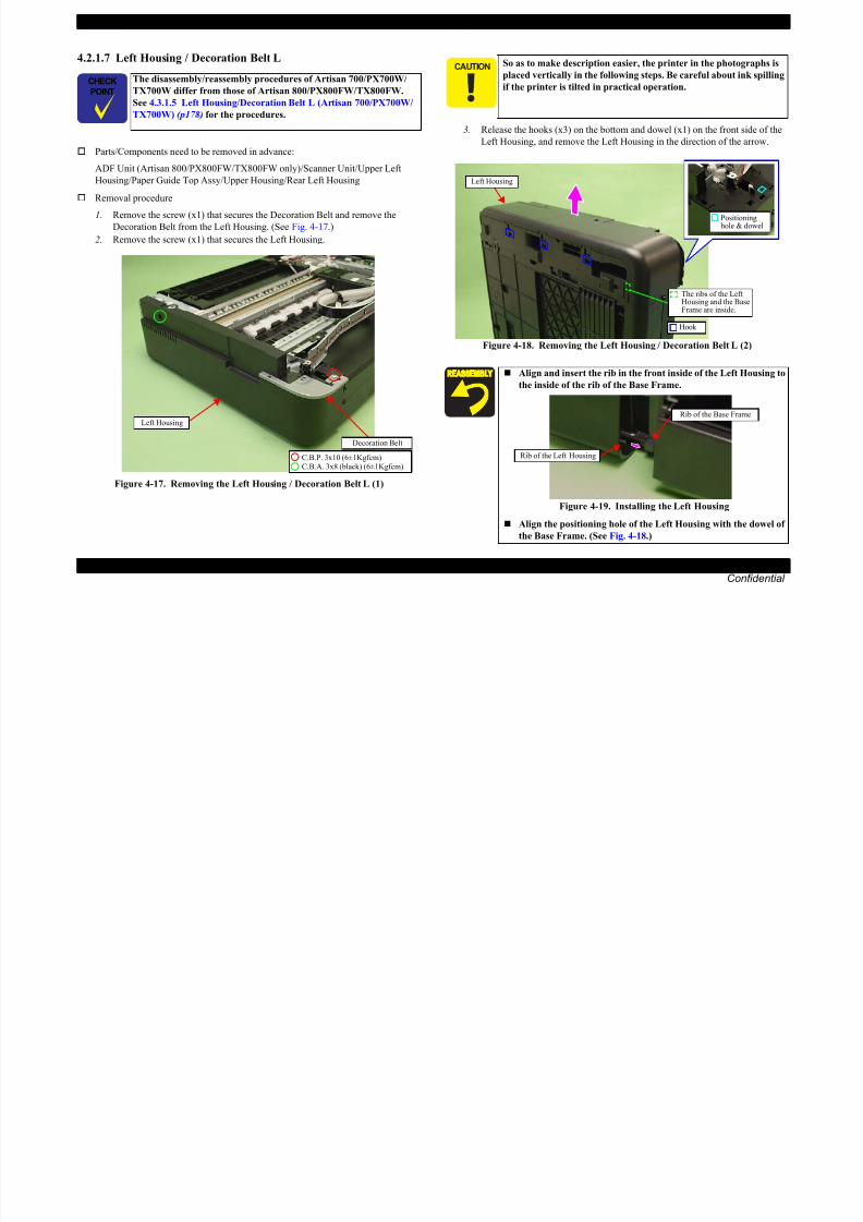
8/22/2019 TX 700 800
http://slidepdf.com/reader/full/tx-700-800 104/234
DISASSEMBLY/ASSEMBLY Disassembly Procedures 104
Confidential
Parts/Components need to be removed in advance:
ADF Unit (Artisan 800/PX800FW/TX800FW only)/Scanner Unit/Upper Left
Housing/Paper Guide Top Assy/Upper Housing/Rear Left Housing
Removal procedure
1. Remove the screw (x1) that secures the Decoration Belt and remove the
Decoration Belt from the Left Housing. (See Fig. 4-17.)
2. Remove the screw (x1) that secures the Left Housing.
Figure 4-17. Removing the Left Housing / Decoration Belt L (1)
Figure 4-18. Removing the Left Housing / Decoration Belt L (2)
C.B.A. 3x8 (black) (6±1Kgfcm)C.B.P. 3x10 (6±1Kgfcm)
Decoration Belt
Left Housing
Align and insert the rib in the front inside of the Left Housing to
the inside of the rib of the Base Frame.
Figure 4-19. Installing the Left Housing
Align the positioning hole of the Left Housing with the dowel of
the Base Frame. (See Fig. 4-18.)
Left Housing
Hook
Positioninghole & dowel
The ribs of the LeftHousing and the BaseFrame are inside.
Rib of the Base Frame
Rib of the Left Housing
EPSON Artisan 800/EPSON Stylus Photo PX800FW/TX800FW/Artisan 700/EPSON Stylus Photo PX700W/TX700W Revision A
4.2.1.8 Stacker Assy
Parts/Components need to be removed in advance:
ADF Unit (Artisan 800/PX800FW/TX800FW only)/Scanner Unit/Upper Left
Housing/Paper Guide Top Assy/Upper Housing
Removal procedure
1. Pull the Stacker Assy.
2 Bend the center of the Stacker Assy and release the dowels (x4) from the
4.2.1.9 Rear ASF Paper Guide Cover
Parts/Components need to be removed in advance:
None
Removal procedure
1. Release the hook (x1) and remove the Rear ASF Paper Guide Cover.
R

8/22/2019 TX 700 800
http://slidepdf.com/reader/full/tx-700-800 105/234
DISASSEMBLY/ASSEMBLY Disassembly Procedures 105
Confidential
2. Bend the center of the Stacker Assy and release the dowels (x4) from the
grooves of the Base Frame, and remove the Stacker Assy.
Figure 4-20. Removing the Stacker Assy
Figure 4-21. Removing the Rear ASF Paper Guide Cover
Stacker AssyDowel
Insert the ribs (x2) of the Rear ASF Paper Guide Cover to the inside
of the Housing, and secure it with the hook (x1).
Hook
Rib
Rear ASF Paper Guide Cover
Rear
EPSON Artisan 800/EPSON Stylus Photo PX800FW/TX800FW/Artisan 700/EPSON Stylus Photo PX700W/TX700W Revision A
4.2.1.10 Rear Right FAX Housing
Parts/Components need to be removed in advance:
The disassembly/reassembly procedures of Artisan 700/PX700W/
TX700W differ from those of Artisan 800/PX800FW/TX800FW.
See 4.3.1.6 Rear Right Housing (Artisan 700/PX700W/TX700W)
(p179) for the procedures.
Point A
Hook B

8/22/2019 TX 700 800
http://slidepdf.com/reader/full/tx-700-800 106/234
DISASSEMBLY/ASSEMBLY Disassembly Procedures 106
Confidential
Parts/Components need to be removed in advance:
ADF Unit (Artisan 800/PX800FW/TX800FW only)/Scanner Unit/Upper Left
Housing/Paper Guide Top Assy/Upper Housing/Hinge
Removal procedure
1. Remove the screws (x3) that secure the Rear Right FAX Housing.
Figure 4-22. Removing the Rear Right FAX Housing (1)
2. Release the ribs (x2) and hook B on the right side, and also release the point
A, then remove the Rear Right FAX Housing by lifting it in the direction of
the arrow. (See Fig. 4-22, Fig. 4-23.)
Figure 4-23. Removing the Rear Right FAX Housing (2)
C.B.A. 3x8 (black) (6±1Kgfcm)
C.B.S. 3x6 (black) (8±1Kgfcm)C.B.P. 3x10 (6±1Kgfcm)
Hook A
Rear Right FAX Housing
When installing the Rear Right FAX Housing, insert the ribs
(x2) of the Rear Right FAX Housing to the inside of the Right
Housing. (See Fig. 4-23.)
When installing the Rear Right FAX Housing, align the point A
of the Rear Right FAX Housing with the inside of the Base
Frame. (See Fig. 4-23.)
Rib
Rear Right FAX Housing
Right Housing
EPSON Artisan 800/EPSON Stylus Photo PX800FW/TX800FW/Artisan 700/EPSON Stylus Photo PX700W/TX700W Revision A
4.2.1.11 Right Housing / Card Cover
Parts/Components need to be removed in advance:
2. Release the dowel (x1) of the front side (See Fig. 4-24.) and hooks (x3) on the bottom of the Right Housing, and remove the Right Housing.
The disassembly/reassembly procedures of Artisan 700/PX700W/
TX700W differ from those of Artisan 800/PX800FW/TX800FW.
See 4.3.1.7 Right Housing/Card Cover (Artisan 700/PX700W/
TX700W) (p180) for the procedures.
When removing the Right Housing, be careful not to let the Card
Cover interfere with the Card Slot Assy or the Card Cover may be
damaged.
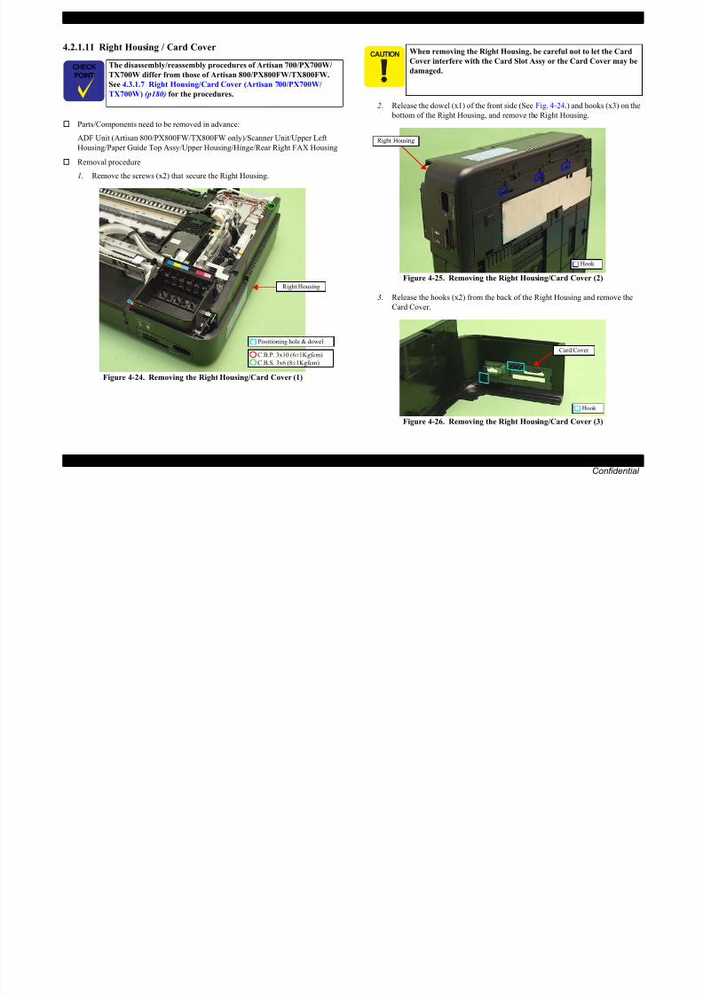
8/22/2019 TX 700 800
http://slidepdf.com/reader/full/tx-700-800 107/234
DISASSEMBLY/ASSEMBLY Disassembly Procedures 107
Confidential
p
ADF Unit (Artisan 800/PX800FW/TX800FW only)/Scanner Unit/Upper Left
Housing/Paper Guide Top Assy/Upper Housing/Hinge/Rear Right FAX Housing
Removal procedure
1. Remove the screws (x2) that secure the Right Housing.
Figure 4-24. Removing the Right Housing/Card Cover (1)
Figure 4-25. Removing the Right Housing/Card Cover (2)
3. Release the hooks (x2) from the back of the Right Housing and remove the
Card Cover.
Figure 4-26. Removing the Right Housing/Card Cover (3)
Positioning hole & dowel
C.B.S. 3x6 (8±1Kgfcm)
C.B.P. 3x10 (6±1Kgfcm)
Right Housing
Right Housing
Hook
Hook
Card Cover
EPSON Artisan 800/EPSON Stylus Photo PX800FW/TX800FW/Artisan 700/EPSON Stylus Photo PX700W/TX700W Revision A
4.2.1.12 Cassette Unit
Parts/Components need to be removed in advance:
None
Removal procedure
1. Hold and pull the grip under the Cassette Unit, and remove the Cassette Unit.
Align and insert the positioning hole of the Right Housing to the
dowel of the Base Frame. (See Fig. 4-24.)
Attach the Card Cover after installing the Right Housing to the
Printer.
When attaching the Card Cover, insert the ribs (x2) of the Card
Cover to the inside of the Right Housing, and secure it with the
hooks (x2).

8/22/2019 TX 700 800
http://slidepdf.com/reader/full/tx-700-800 108/234
DISASSEMBLY/ASSEMBLY Disassembly Procedures 108
Confidential
Figure 4-28. Removing the Cassette Unit
Figure 4-27. Attaching the Card Cover
Hook
Rib
Right Housing
Card Cover
When replacing the cork A/B, wipe the attaching position with
ethanol, and attach it without any gap at the point A.
When attaching the cork B, align the cutout to the place shown
in Fig. 4-29.
Figure 4-29. Attaching the cork
Cassette Unit
Gripe
Cork ACork B
Cutout
Point A
EPSON Artisan 800/EPSON Stylus Photo PX800FW/TX800FW/Artisan 700/EPSON Stylus Photo PX700W/TX700W Revision A
4.2.1.13 Paper Guide Top Assy
Parts/Components need to be removed in advance:
None
Removal procedure
1. Open the Scanner Unit.2. Release the hooks (x2) and remove the Paper Guide Top Assy.
4.2.2 Removing the Circuit Board
4.2.2.1 Panel Unit
The disassembly/reassembly procedures of Artisan 700/PX700W/
TX700W differ from those of Artisan 800/PX800FW/TX800FW.
See 4.3.2.1 Panel Unit (Artisan 700/PX700W/TX700W) (p181) forthe procedures.

8/22/2019 TX 700 800
http://slidepdf.com/reader/full/tx-700-800 109/234
DISASSEMBLY/ASSEMBLY Disassembly Procedures 109
Confidential
Figure 4-30. Removing the Paper Guide Top Assy
Parts/Components need to be removed in advance:
Upper Left Housing
Removal procedure
1. Remove the Grounding Wire. (See 4.2.1.5 Upper Housing Step1 (p101).)
2. Remove the Panel Spring (x1). (See Fig. 4-31.)
3. Remove the screws (x2) that secure the Ratchet Holder Assy.
Figure 4-31. Removing the Ratchet Holder Assy (1)
Align and insert the dowels (x2) of the Paper Guide Top Assy to the
grooves of the Housing, and secure it with the hooks (x2). (See Fig.4-30.)
Paper Guide Top Assy
Hook
Groove & dowel of the Housing
C.B.P. 3x10 (6±1Kgfcm)
Ratchet Holder Assy
Panel Spring
EPSON Artisan 800/EPSON Stylus Photo PX800FW/TX800FW/Artisan 700/EPSON Stylus Photo PX700W/TX700W Revision A
4. Slide the Ratchet Holder Assy to the left, and release the rib A. (See Fig.
4-32.)
5. Slide the Ratchet Holder Assy to the front to remove it from the Upper
Housing, and remove it from the Panel Unit.
8. Disconnect the Panel FFC from the connector of the Panel Unit. (See Fig.
4-34.)
9. Remove the screw (x1) that secures the Panel Unit and remove the Panel Unit
from the Upper Housing.
Step 4
Panel Unit
Ratchet Holder Assy Panel UnitUpper Housing
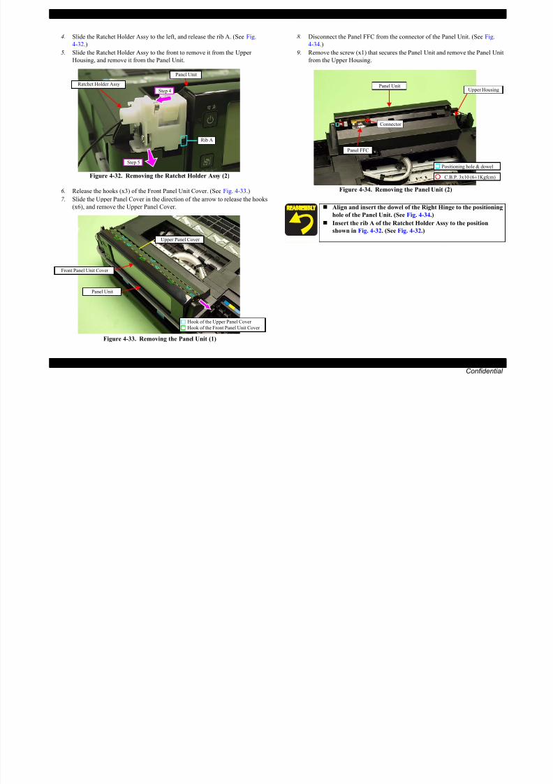
8/22/2019 TX 700 800
http://slidepdf.com/reader/full/tx-700-800 110/234
DISASSEMBLY/ASSEMBLY Disassembly Procedures 110
Confidential
Figure 4-32. Removing the Ratchet Holder Assy (2)
6. Release the hooks (x3) of the Front Panel Unit Cover. (See Fig. 4-33.)
7. Slide the Upper Panel Cover in the direction of the arrow to release the hooks
(x6), and remove the Upper Panel Cover.
Figure 4-33. Removing the Panel Unit (1)
Figure 4-34. Removing the Panel Unit (2)
Rib A
Step 5
Front Panel Unit Cover
Panel Unit
Upper Panel Cover
Hook of the Upper Panel Cover
Hook of the Front Panel Unit Cover
Align and insert the dowel of the Right Hinge to the positioning
hole of the Panel Unit. (See Fig. 4-34.) Insert the rib A of the Ratchet Holder Assy to the position
shown in Fig. 4-32. (See Fig. 4-32.)
Positioning hole & dowel
C.B.P. 3x10 (6±1Kgfcm)
Panel FFC
Connector
EPSON Artisan 800/EPSON Stylus Photo PX800FW/TX800FW/Artisan 700/EPSON Stylus Photo PX700W/TX700W Revision A
4.2.2.2 Main Board / Grounding Plate M/B
Parts/Components need to be removed in advance:
The disassembly/reassembly procedures of Artisan 700/PX700W/
TX700W differ from those of Artisan 800/PX800FW/TX800FW.
See 4.3.2.2 Main Board/Grounding Plate M/B (Artisan 700/
PX700W/TX700W) (p183) for the procedures.
CN21 CR Motor Cable Black 2
CN22 PF Motor Cable White 2
CN24 Decompression Pump Motor Cable Red 2
Table 4-4. Connectors on the Main Board
CN No. Cable/FFCConnector
Color
Number of pins
Artisan 800/
PX800FW/
TX800FW
Artisan 700/
PX700W/
TX700W

8/22/2019 TX 700 800
http://slidepdf.com/reader/full/tx-700-800 111/234
DISASSEMBLY/ASSEMBLY Disassembly Procedures 111
Confidential
ADF Unit (Artisan 800/PX800FW/TX800FW only)/Scanner Unit/Upper Left
Housing/Paper Guide Top Assy/Upper Housing/Hinge/Rear Right FAX Housing/
Right Housing
Removal procedure
1. Disconnect all the cables and FFCs from the connectors on the Main Board.
Figure 4-35. Connector position on the Main Board
Table 4-4. Connectors on the Main Board
CN No. Cable/FFCConnector
Color
Number of pins
Artisan 800/
PX800FW/
TX800FW
Artisan 700/
PX700W/
TX700W
CN1 Head FFC -- 14
CN2 Head FFC -- 14CN3 Head FFC -- 14
CN4 Head FFC -- 14
CN5 CSIC FFC -- 13
CN6 CR Encoder FFC -- 7
CN7 SUB FFC -- 9
CN8 PF Encoder FFC -- 4
CN9 PE Sensor Cable White 3
CN10 Scanner Cover Open Sensor FFC -- 4
CN12 Photo Tray Sensor Cable Yellow 2
CN13 Duplex Unit Sensor Cable White 2
CN14 CDR Tray Sensor Cable Red 2
CN19 Plunger Cable Black 2
CN24 Decompression Pump Motor Cable Red 2
CN25 ADF Motor Cable Black 4 ---
CN31 STG FFC -- 8
CN33 Panel FFC -- 28 19
CN36 I/F B FFC (FAX) -- 18 ---
CN41 Scanner Carriage FFC -- 15
CN49 Scanner CR Encoder FFC -- 6
CN51 ADF Sensor Cable White 4 ---
CN501 Power Supply Unit Cable White 5
CN501
CN22
CN21
CN24
CN49
CN25 CN14
CN13 CN8
CN41 CN10
CN51
CN12
CN9 CN33
CN6 CN4 CN3 CN2
CN1
CN36
CN5
CN19
CN31
CN7
EPSON Artisan 800/EPSON Stylus Photo PX800FW/TX800FW/Artisan 700/EPSON Stylus Photo PX700W/TX700W Revision A
2. Remove the screw (x1) that secures the Right Cable Frame and the Main
Board. (See Fig. 4-36.)
3. Remove the screw (x1) that secures the Ferrite Core Holder A, and remove
the Ferrite Core Holder A. (See Fig. 4-36.)
4. Remove the screw (x1) that secures the Grounding Plate M/B, and remove the
Grounding Plate M/B. (See Fig. 4-36.)
5. Remove the screws (x3) that secure the Main Board Unit and remove theMain Board Unit.
Main Board
1. Disconnect the I/F-B FFC from the FAX board. (Artisan 800/PX800FW/
TX800FW only) (See Fig. 4-37.)
2. Remove the screws (x7) that secure the Upper Shield Plate M/B, and remove
the Upper Shield Plate M/B.
Rear Upper Shield Plate M/B

8/22/2019 TX 700 800
http://slidepdf.com/reader/full/tx-700-800 112/234
DISASSEMBLY/ASSEMBLY Disassembly Procedures 112
Confidential
Figure 4-36. Removing the Main Board Unit
Figure 4-37. Removing the Main Board (1)
3. Remove the screws (x3) that secure the Main Board and remove the Main
Board from the Lower Shield Plate M/B.
Figure 4-38. Removing the Main Board (2)
C.B.P. 3x10 (6±1Kgfcm)
Step 3
Holder IC Shield Plate
Ferrite Core Holder A
C.B.P. 3x8 (6±1Kgfcm)C.B.S. 3x6 (8±1Kgfcm)C.B.S. 3x6 (6±1Kgfcm)
C.B.S.(P2) 3x8 (8±1Kgfcm) C.B.S. 3x6 (5±0.5Kgfcm)
Step 2
Step 4
Positioning hole & dowel
Right Cable Frame
Main Board Unit
Grounding Plate M/B
Dowel & groove
Rear Bottom
C.B.S. 3x6 (8±1Kgfcm)
C.B.S. 3x6 (4±1Kgfcm)
C.P. 3x6 (4±1Kgfcm)
I/F-B FFC
Positioning hole & dowel
1
2
3
C.B.S. 3x6 (8±1Kgfcm)
C.B.S. 3x10 (8±1Kgfcm)
Lower Shield Plate M/B
Main Board
EPSON Artisan 800/EPSON Stylus Photo PX800FW/TX800FW/Artisan 700/EPSON Stylus Photo PX700W/TX700W Revision A
FAX Board (IF-B Board) (Artisan 800/PX800FW/TX800FW only)
1. Disconnect the I/F-B FFC from the FAX Board. (See Fig. 4-39.)
2. Remove the screws (x4) that secure the Shield Plate FAX, and remove the
Shield Plate FAX from the Upper Shield Plate M/B.
3. Remove the screws (x4) that secure the FAX Board and remove the FAX
Board from the Upper Shield Plate M/B.
Top
1 4
Upper Shield Plate M/B

8/22/2019 TX 700 800
http://slidepdf.com/reader/full/tx-700-800 113/234
DISASSEMBLY/ASSEMBLY Disassembly Procedures 113
Confidential
Figure 4-39. Removing the FAX Board (1)
Figure 4-40. Removing the FAX Board (2)
Upper Shield Plate M/B
Shield Plate FAX
Rear
C.B.S. 3x6 (4±1Kgfcm)
C.P. 3x6 (4±1Kgfcm)
I/F-B FFC
Dowel & groove
Align the positioning holes (x2) of the Main Board with the
dowels (x2) of the Upper Shield Plate M/B. (See Fig. 4-38.)
When installing the Main Board, tighten the screws in the order
shown in Fig. 4-38.
Align the dowels (x2) of the Lower Shield Plate M/B with thegrooves (x2) of the Upper Shield Plate M/B. (See Fig. 4-37.)
Align the positioning holes (x2) of the FAX Board with the
dowels of the Upper Shield Plate M/B. (See Fig. 4-40.)
When installing the FAX Board, tighten the screws in the order
shown in Fig. 4-40.
Align the grooves (x2) of the Shield Plate FAX with the dowels
(x2) of the Upper Shield Plate M/B. (See Fig. 4-39.)
Align the positioning hole (x1) of the Main Board with the dowel
(x1) of the Upper Shield Plate M/B. (See Fig. 4-36.)
C.B.S. 3x6 (4±0.5Kgfcm)
23
FAX Board Positioning hole & dowel
EPSON Artisan 800/EPSON Stylus Photo PX800FW/TX800FW/Artisan 700/EPSON Stylus Photo PX700W/TX700W Revision A
When connecting the I/F-B FFC to the Main Board, connect it
as shown in Fig. 4-41.
Attach this part to theFAX Board side.
I/F-B FFC
Main Board
When attaching the CR Encoder FFC, follow the procedure
below.
1. Put the CR Encoder FFC through the ferrite core.
2. Connect the CR Encoder FFC to the connector (CN6) on
the Main Board.
3. Insert the rib of the Ferrite Core Holder B to the hole of the
Main Board, and secure it with the screw (x1).
Ferrite Core Holder B

8/22/2019 TX 700 800
http://slidepdf.com/reader/full/tx-700-800 114/234
DISASSEMBLY/ASSEMBLY Disassembly Procedures 114
Confidential
Figure 4-41. Connecting the I/F-B FFC
Attach the Ferrite Core Holder A as follows.
1. Align the dowels (x2) of the Main Board Unit with thepositioning holes (x2) of the Holder IC Shield Plate.
2. Secure the Ferrite Core Holder A and the Holder IC Shield
Plate to the Main Board Unit with the screw. (See Fig.
4-36.)
Align the dowel (x1) of the Main Board Unit with the
positioning hole (x1) of the Right Cable Frame. (See Fig. 4-36.)
Insert the rib (x1) of the Grounding Plate M/B to the hole of the
Main Board Unit, and align the positioning hole (x1) of the
Grounding Plate M/B with the dowel (x1) of the Main Board
Unit, and attach the Grounding Plate M/B. (See Fig. 4-36, Fig.
4-42.)
Figure 4-42. Attaching the Grounding Plate M/B
Hole
Rib
Grounding Plate M/B
Figure 4-43. Attaching the CR Encoder FFC
For routing cables and FFCs, see 4.4 Routing FFC/cables
(p189).
When replacing the Main Board, the MAC address need to be set if
the EEPROM data could not be read from the old Main Board. In
this case, attach the new “Label, MAC address (Parts number:
1489231)” to the position shown in Fig. 4-44 and execute
“5.2.6 MAC Address Setting (p208)”.
Figure 4-44. Position for the MAC Address Label
C.B.S. 3x6 (5±0.5Kgfcm)
CN6
CR Encoder FFC
Ferrite core
Ferrite Core Holder B
Align and insert the rib ofthe Ferrite Core Holder B
Label, MAC address
EPSON Artisan 800/EPSON Stylus Photo PX800FW/TX800FW/Artisan 700/EPSON Stylus Photo PX700W/TX700W Revision A
4.2.2.3 Power Supply Unit
Parts/Components need to be removed in advance:
ADF Unit (Artisan 800/PX800FW/TX800FW only)/Scanner Unit/Upper Left
Housing/Paper Guide Top Assy/Upper Housing/Rear Left Housing/Left Housing
Removal procedure
1. Peel off the PF Encoder FFC from the Power Supply Unit. (See Fig. 4-45.)
2. Disconnect the Power Supply Unit cable from the connector of the Power
Supply Unit. (See Fig. 4-45.)
Route the Power Supply Unit Cable through the groove of the
Base Frame, then install the Power Supply Unit to the Base
Frame.

8/22/2019 TX 700 800
http://slidepdf.com/reader/full/tx-700-800 115/234
DISASSEMBLY/ASSEMBLY Disassembly Procedures 115
Confidential
pp y ( g )
3. Remove the screws (x2) that secure the Power Supply Unit, and remove the
Power Supply Unit from the Base Frame.
Figure 4-45. Removing the Power Supply Unit
Double-sided tape
Rib
Connector
Power Supply Unit cable
PF Encoder FFC
C.B.P. 3x8 (6±1Kgfcm)C.B.S. 3x6 (8±1Kgfcm)
Power Supply Unit
Figure 4-46. Installing the Power Supply Unit
Install the Power Supply Unit inside the ribs (x2) of the Base
Frame. (See Fig. 4-45)
Be careful not to damage the Power Supply Unit cable by
catching it with the screw when screwing. (See Fig. 4-45)
Secure the PF Encoder FFC to the Power Supply Unit with thedouble-sided tape. (See Fig. 4-45)
Power Supply Unit Cable
Groove of the Base Frame
EPSON Artisan 800/EPSON Stylus Photo PX800FW/TX800FW/Artisan 700/EPSON Stylus Photo PX700W/TX700W Revision A
4.2.2.4 Wireless LAN Board
Parts/Components need to be removed in advance:
ADF Unit (Artisan 800/PX800FW/TX800FW only)/Scanner Unit/Upper Left
Housing/Paper Guide Top Assy/Upper Housing/Hinge/Rear Right FAX Housing/
Right Housing
Removal procedure
1. Remove the screws (x2) that secure the Wireless LAN Board, and remove the
Wireless LAN Board from the hooks (x2) of the Base Frame.
2. Disconnect the Wireless LAN cable from the connector and remove the
Wireless LAN Board.
Connector
Wireless LAN cable

8/22/2019 TX 700 800
http://slidepdf.com/reader/full/tx-700-800 116/234
DISASSEMBLY/ASSEMBLY Disassembly Procedures 116
Confidential
Figure 4-47. Removing the Wireless LAN Board (1)
Figure 4-48. Removing the Wireless LAN Board (2)
Wireless LAN Board
C.B.P. 3x8 (6±1Kgfcm)
Hook
When installing the Wireless LAN Board, align it with the hooks
(x2) of the Base Frame. (See Fig. 4-47)
Wireless LANBoard
EPSON Artisan 800/EPSON Stylus Photo PX800FW/TX800FW/Artisan 700/EPSON Stylus Photo PX700W/TX700W Revision A
4.2.2.5 Card Slot Assy 2. Disconnect the AID cable from the connector on the SUB Board, and remove
the Card Slot Assy.
The disassembly/reassembly procedures of EPSON Artisan 700/
EPSON Stylus Photo PX700W/TX700W differ from those of
EPSON Artisan 800/EPSON Stylus Photo PX800FW/
TX800FW. See 4.3.2.3 Card Slot Assy (Artisan 700/PX700W/
TX700W) (p186) for the procedures.
The Card Slot Assy includes the SUB Board and the STG
Board.
When powering this product high-voltage current may be applied
AID cable
Card Slot AssyConnector on the SUB Board

8/22/2019 TX 700 800
http://slidepdf.com/reader/full/tx-700-800 117/234
DISASSEMBLY/ASSEMBLY Disassembly Procedures 117
Confidential
Parts/Components need to be removed in advance:
ADF Unit (Artisan 800/PX800FW/TX800FW only)/Scanner Unit/Upper Left
Housing/Paper Guide Top Assy/Upper Housing/Hinge/Rear Right FAX Housing/
Right Housing/Main Board Unit/Wireless LAN Board/CSIC Assy/Cartridge Box
Unit/Ink Supply Tube Assy
Removal procedure
1. Remove the screws (x2) that secure the Card Slot Assy and remove the
Grounding Plate.
Figure 4-49. Removing the Card Slot Assy (1)
Figure 4-50. Removing the Card Slot Assy (2)
When powering this product, high-voltage current may be applied
on the SUB Board. To prevent ELECTRIC SHOCK, do not touch
the SUB Board section when the power is ON.
If the shock should happen, the flowing current is very tiny, about a
few hundreds μA, therefore it will not do any harm on the human
body.
C.B.P. 3x8 (6±1Kgfcm)
Grounding Plate
Card Slot Assy
Positioning hole & dowel
Dowel & groove
Connect the AID cable properly to the connector on the SUB
Board. (See Fig. 4-50.)
Align the grooves (x2) of the Card Slot Assy with the dowels (x2)of the Base Frame. (See Fig. 4-49.)
When attaching the Grounding Plate, install it over the Card
Slot Assy, and align the positioning hole of the Grounding Plate
with the dowel of the Base Frame, and tighten them together
with the screw. (See Fig. 4-49.)
For routing the FFCs, see 4.4 Routing FFC/cables (p189).
EPSON Artisan 800/EPSON Stylus Photo PX800FW/TX800FW/Artisan 700/EPSON Stylus Photo PX700W/TX700W Revision A
4.2.3 Disassembling the Printer Mechanism
4.2.3.1 Printhead (TBD)
Parts/Components need to be removed in advance:
ADF Unit (Artisan 800/PX800FW/TX800FW only)/Scanner Unit/Upper Left
Housing/Paper Guide Top Assy/Upper Housing Removal procedure
1. Turn the Spur Gear in the direction of the arrow, and release the Carriage
Lock. (See Fig. 4-52.)
2. Move the Carriage Unit to the center.
When removing the Printhead the ink leaked from the junction
Spur Gear Carriage Lock is under
the Carriage Unit.
Carriage Unit

8/22/2019 TX 700 800
http://slidepdf.com/reader/full/tx-700-800 118/234
DISASSEMBLY/ASSEMBLY Disassembly Procedures 118
Confidential
Figure 4-52. Releasing the Carriage Lock
When removing the Printhead, the ink leaked from the junction
point of the Ink Supply Tube Assy and the Printhead might
penetrate into the Decompression tube. In such a case, the ink will
adversely affect the ink supply to the Printhead; therefore, when
removing the Printhead, make sure to replace the Ink Supply IC
Holder Assy together.
Figure 4-51. Ink Supply IC Holder Assy
Decompression tube
Carriage Lock
EPSON Artisan 800/EPSON Stylus Photo PX800FW/TX800FW/Artisan 700/EPSON Stylus Photo PX700W/TX700W Revision A
3. Remove the screws (x4) that secure the Printhead and the Ink Supply TubeAssy, and detach the Printhead from the Carriage Unit.
5. Remove the screws (x2) that secure the Ink Supply Tube Assy and remove the
When handling the Printhead, make sure not to touch or
damage the nozzle plate surface of the head. (See Fig. 4-54.)
Do not damage or contaminate the CR Seal, or touch it with
bare hands either. (See Fig. 4-56.)
In the next steps, make sure to take measures against
contamination of the surroundings from the ink leaked from
the tube such as receiving it with BEMCOT or the like.
Using a piece of clean BEMCOT or the like, wipe off the ink
leaked from the Ink Supply Tube Assy when removing the
Printhead.
Make sure not to touch the joint point of the Printhead and theInk Supply Tube Assy. (See Fig. 4-55.)

8/22/2019 TX 700 800
http://slidepdf.com/reader/full/tx-700-800 119/234
DISASSEMBLY/ASSEMBLY Disassembly Procedures 119
Confidential
Figure 4-53. Removing the Printhead (1)
4. Disconnect the Head FFC (x2) from the Printhead.
Figure 4-54. Removing the Printhead (2)
5. Remove the screws (x2) that secure the Ink Supply Tube Assy and remove the
Ink Supply Tube Assy from the Printhead, then remove the Printhead.
Figure 4-55. Removing the Printhead (3)
Printhead
Ink Supply Tube Assy
C.B.P. 2x10 (3±0.5Kgfcm)
1
23
4
Printhead
Nozzle Plate
Head FFC
1
C.B.P. 2x10 (3±0.5Kgfcm)
Printhead
EPSON Artisan 800/EPSON Stylus Photo PX800FW/TX800FW/Artisan 700/EPSON Stylus Photo PX700W/TX700W Revision A
4.2.3.2 CR Scale
Parts/Components need to be removed in advance:
ADF Unit (Artisan 800/PX800FW/TX800FW only)/Scanner Unit/Upper Left
Housing/Paper Guide Top Assy/Upper Housing
Removal procedure
Make sure to connect the Head FFC (x2) securely. (See Fig.
4-56.)
When installing the Printhead, confirm the CR Seal is not
folded or out of position, then install it without any gap in
between.
When the CR Seal gets out of position, make sure to align the
positioning holes (x2) of it with the dowels (x2) on the CarriageUnit, then install it without any gap. Do not touch the CR Scale with bare hands.
Do not damage or contaminate the CR Scale.
Take care not to damage (extend too much) the Torsion Spring

8/22/2019 TX 700 800
http://slidepdf.com/reader/full/tx-700-800 120/234
DISASSEMBLY/ASSEMBLY Disassembly Procedures 120
Confidential
1. Release the Carriage Lock and move the Carriage Unit to the center. (See
4.2.3.1 Printhead (TBD) Step1 (p118).)
2. Release the right side of the CR Scale from the hook.3. Pull out the CR Scale from the slit of the CR Encoder Sensor.
Figure 4-57. Removing the CR Scale(1)
Figure 4-56. Installing the CR Seal
When installing the Ink Supply Tube Assy to the Printhead,
make sure to install it without any gap between the joint point
of them. (See Fig. 4-53.)
Tighten the screws in the order given in Fig. 4-55.
Confirm that there is no ink penetrating into the
Decompression Tube located inside the Ink Supply Tube Assy.
If such ink penetration is observed, make sure to replace the
Ink Supply IC Holder Assy (p125) together with the Printhead.(See Fig. 4-51.)
Positioning hole & dowel
Carriage Unit
CR Seal
g ( ) p g
16.43.
CR Scale
Slit of CR Encoder Sensor
Hook
CR Scale
EPSON Artisan 800/EPSON Stylus Photo PX800FW/TX800FW/Artisan 700/EPSON Stylus Photo PX700W/TX700W Revision A
4. Detach the Torsion Spring 16.43 from the hook of the Main Frame.
5. Rotate the CR Scale 90 degrees as shown below, and remove it from the Main
Frame.
4.2.3.3 PF Encoder
Parts/Components need to be removed in advance:
ADF Unit (Artisan 800/PX800FW/TX800FW only)/Scanner Unit/Upper Left
Housing/Paper Guide Top Assy/Upper Housing/Rear Left Housing/Left Housing/
Decoration Belt
Removal procedure
90 degrees
Chipped part
Do not touch the PF Scale with bare hands.
Do not damage or contaminate the PF Scale.
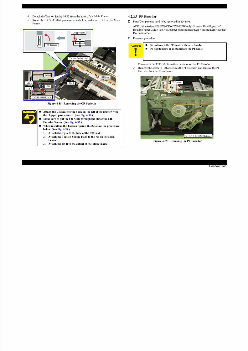
8/22/2019 TX 700 800
http://slidepdf.com/reader/full/tx-700-800 121/234
DISASSEMBLY/ASSEMBLY Disassembly Procedures 121
Confidential
Figure 4-58. Removing the CR Scale(2)
1. Disconnect the FFC (x1) from the connector on the PF Encoder.
2. Remove the screw (x1) that secures the PF Encoder, and remove the PFEncoder from the Main Frame.
Figure 4-59. Removing the PF Encoder
Attach the CR Scale to the hook on the left of the printer with
the chipped part upward. (See Fig. 4-58.)
Make sure to put the CR Scale through the slit of the CR
Encoder Sensor. (See Fig. 4-57.)
When installing the Torsion Spring 16.43, follow the procedure
below. (See Fig. 4-58.)
1. Attach the leg A to the hole of the CR Scale.
2. Attach the Torsion Spring 16.43 to the rib on the Main
Frame.
3. Attach the leg B to the cutout of the Main Frame.
Rib
Torsion Spring 16.43
Leg A
Leg B
Cutout
Hook
CR Scale
Torsion Spring 16.43
FFC PF Encoder
C.B.S. 2x5 (3±1Kgfcm)
EPSON Artisan 800/EPSON Stylus Photo PX800FW/TX800FW/Artisan 700/EPSON Stylus Photo PX700W/TX700W Revision A
4.2.3.4 PF Scale
Parts/Components need to be removed in advance:
ADF Unit (Artisan 800/PX800FW/TX800FW only)/Scanner Unit/Upper Left
Housing/Paper Guide Top Assy/Upper Housing/Rear Left Housing/Left Housing/
Decoration Belt/PF Encoder
Removal procedure
4.2.3.5 Decompression Pump Unit
Parts/Components need to be removed in advance:
ADF Unit (Artisan 800/PX800FW/TX800FW only)/Scanner Unit/Upper Left
Housing/Paper Guide Top Assy/Upper Housing/Hinge/Rear Right FAX Housing/
Right Housing/Main Board
Removal procedure
1. Remove the decompression tube from the socket of the Cartridge Box Unit.
(See Fig. 4-61.)
2. Release the decompression tube from the groove on the Base Frame.
Do not touch the PF Scale with bare hands.
Do not damage or contaminate the PF Scale.

8/22/2019 TX 700 800
http://slidepdf.com/reader/full/tx-700-800 122/234
DISASSEMBLY/ASSEMBLY Disassembly Procedures 122
Confidential
1. Push the Tensioner in the direction of the arrow, and remove the PF Timing
Belt. (See Fig. 4-60.)2. Remove the PF Scale together with the Spur Gear.
3. Peel off the PF Scale from the Spur Gear.
Figure 4-60. Removing the PF Scale
p g
Figure 4-61. Removing the Decompression Pump Unit
When installing the PF Scale, make sure to align both the center
holes of the Spur Gear and the PF Scale properly, and secure them
with the double-sided tape (See Fig. 4-60.)
Rear sidePF Scale
Double-sided tape
Spur Gear
PF Scale
PF Timing Belt
Tensioner
Right side Decompression Pump Unit
Decompression tube
Groove on Base Frame
Socket for the tube
Decompression tube
Section A
Section B
EPSON Artisan 800/EPSON Stylus Photo PX800FW/TX800FW/Artisan 700/EPSON Stylus Photo PX700W/TX700W Revision A
3. Remove the screws (x3) that secure the Decompression Pump Unit, and
remove the Decompression Pump Unit from the Base Frame.
Decompression Pump Unit
Decompression Pump Motor cable
When routing the Decompression Pump Motor cable, make
sure to secure it with the dowels (x6) and the hook on top of the
Decompression Pump Unit as shown in Fig. 4-62.
When routing the decompression tube, confirm no clipped part
or fold on the tube. (See Fig. 4-61, Fig. 4-63.)
Decompression Pump Unit

8/22/2019 TX 700 800
http://slidepdf.com/reader/full/tx-700-800 123/234
DISASSEMBLY/ASSEMBLY Disassembly Procedures 123
Confidential
Figure 4-62. Removing the Decompression Pump Unit
Base Frame
Hook
Dowels (x6)
P.W. 3.3x0.5x10C.B.P. 3x14 (6±1Kgfcm)
C.B.P. 3x8 (6±1Kgfcm)Figure 4-63. Installing the Decompression Pump Unit
Put the decompression tube through the groove on the Base
Frame (section A, B), and route it behind the FFC. (See Fig.
4-61.)
Make sure to insert the decompression tube into the socket on
the Cartridge Box Unit to the full to its base. (See Fig. 4-61.)
Decompression tube
EPSON Artisan 800/EPSON Stylus Photo PX800FW/TX800FW/Artisan 700/EPSON Stylus Photo PX700W/TX700W Revision A
4.2.3.6 CSIC Assy
Parts/Components need to be removed in advance:
ADF Unit (Artisan 800/PX800FW/TX800FW only)/Scanner Unit/Upper Left
Housing/Paper Guide Top Assy/Upper Housing
In the case of Artisan 700/PX700W/TX700W, removing the Right
Rear Housing (p179) and the Right Housing (p180) earlier will makethe operation easier.
FFC
Hook
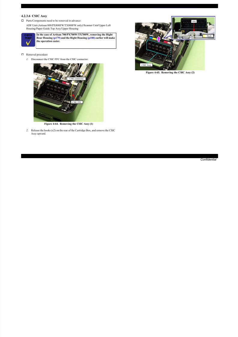
8/22/2019 TX 700 800
http://slidepdf.com/reader/full/tx-700-800 124/234
DISASSEMBLY/ASSEMBLY Disassembly Procedures 124
Confidential
Removal procedure
1. Disconnect the CSIC FFC from the CSIC connector.
Figure 4-64. Removing the CSIC Assy (1)
2. Release the hooks (x2) on the rear of the Cartridge Box, and remove the CSIC
Assy upward.
Figure 4-65. Removing the CSIC Assy (2)
CSIC connector
CSIC FFC
CSIC Assy
EPSON Artisan 800/EPSON Stylus Photo PX800FW/TX800FW/Artisan 700/EPSON Stylus Photo PX700W/TX700W Revision A
4.2.3.7 Ink Supply IC Holder Assy
Parts/Components need to be removed in advance:
ADF Unit (Artisan 800/PX800FW/TX800FW only)/Scanner Unit/Upper Left
Housing/Paper Guide Top Assy/Upper Housing/Printhead/Hinge/Rear Right FAX
Housing /Right Housing/Main Board/CSIC Assy/ Wireless LAN Board
Removal procedure
2. Disconnect the decompression tube from the socket on the Cartridge Box
Unit. (See Fig. 4-61.)
3. Remove the screws (x7) that secure the Cartridge Box Unit.
The Ink Supply IC Holder Assy consists of the Ink Supply Tube
Assy and the Cartridge Box Unit. (See Fig. 4-51.)
Cartridge Box Unit
GroundingPlate
RightCartridge Box UnitTop
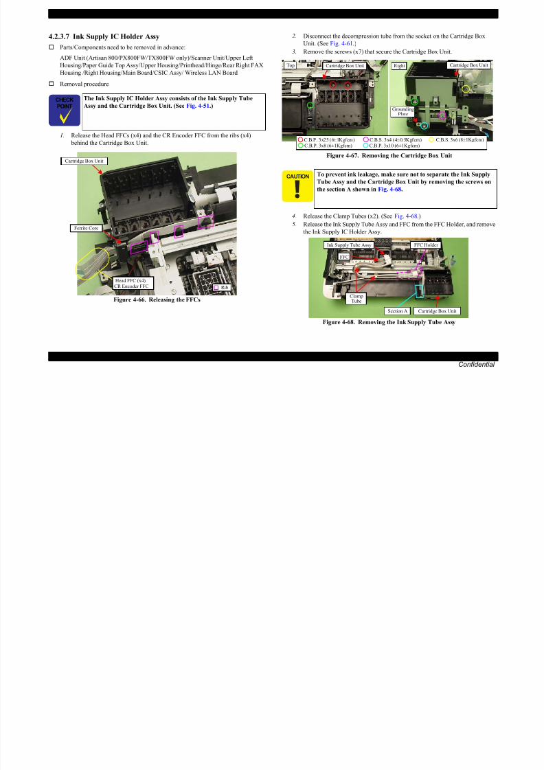
8/22/2019 TX 700 800
http://slidepdf.com/reader/full/tx-700-800 125/234
DISASSEMBLY/ASSEMBLY Disassembly Procedures 125
Confidential
1. Release the Head FFCs (x4) and the CR Encoder FFC from the ribs (x4)
behind the Cartridge Box Unit.
Figure 4-66. Releasing the FFCs
Figure 4-67. Removing the Cartridge Box Unit
4. Release the Clamp Tubes (x2). (See Fig. 4-68.)5. Release the Ink Supply Tube Assy and FFC from the FFC Holder, and remove
the Ink Supply IC Holder Assy.
Figure 4-68. Removing the Ink Supply Tube Assy
Cartridge Box Unit
Rib
Ferrite Core
Head FFC (x4) CR Encoder FFC
To prevent ink leakage, make sure not to separate the Ink Supply
Tube Assy and the Cartridge Box Unit by removing the screws on
the section A shown in Fig. 4-68.
Plate
C.B.P. 3x10 (6±1Kgfcm)C.B.P. 3x8 (6±1Kgfcm)C.B.P. 3x25 (6±1Kgfcm) C.B.S. 3x4 (4±0.5Kgfcm) C.B.S. 3x6 (8±1Kgfcm)
Cartridge Box Unit
Ink Supply Tube Assy
FFC
ClampTube
FFC Holder
Section A
EPSON Artisan 800/EPSON Stylus Photo PX800FW/TX800FW/Artisan 700/EPSON Stylus Photo PX700W/TX700W Revision A
Make sure to insert the decompression tube into the socket on
the Cartridge Box Unit to the full to its base. (See Fig. 4-61.)
Make sure to align the positioning hole (x1) on the Cartridge
Box Unit with the dowel (x1) of the Base Frame when
reassembling them. (See Fig. 4-69.)
When installing the Cartridge Box Unit, make sure to secure
the hooks (x2) on the Main Frame to their positioning holes(x2). (See Fig. 4-69.)
Secure the convex sections (x2) of the Clamp Tube into the hole
of it from outside to inside as shown in Fig. 4-70.
Fold the wings inward as shown in Fig. 4-70.
Clamp Tube
Convex of Clamp Tube

8/22/2019 TX 700 800
http://slidepdf.com/reader/full/tx-700-800 126/234
DISASSEMBLY/ASSEMBLY Disassembly Procedures 126
Confidential
Figure 4-69. Installing the Cartridge Box Unit
Make sure to attach the grounding plate to the place shown in
Fig. 4-67, and secure it with the screw.
Positioning hole & dowel
Positioning hole & hook
Figure 4-70. Installing the Clamp Tube
When installing the Ink Supply IC Holder Assy, make sure to
remove slack around the section B by moving the Carriage Unit
between the 0-digit side and the 80-digit side a few times.
Figure 4-71. Installing the Ink Supply IC Holder Assy
For routing the FFCs, see 4.4 Routing FFC/cables (p189).
Wings of Clamp Tube Hole on Clamp Tube
Section B
EPSON Artisan 800/EPSON Stylus Photo PX800FW/TX800FW/Artisan 700/EPSON Stylus Photo PX700W/TX700W Revision A
4.2.3.8 Ink System
Parts/Components need to be removed in advance:
ADF Unit (Artisan 800/PX800FW/TX800FW only)/Scanner Unit/Upper Left
4. Disconnect the AID cable from the connector on the SUB Board.(See Fig.
4-73.)
When powering this product, high-voltage current may be applied
on the SUB Board. To prevent ELECTRIC SHOCK, do not touch
the SUB Board section when the power is ON.
If the shock should happen, the flowing current is very tiny, about a
few hundreds μA, therefore it will not do any harm on the human
body.
So as to make description easier, the printer in the photographs is
placed vertically in the following steps. Be careful about ink spilling
if the printer is tilted in practical operation.
Be careful about ink spilling from the Waste Ink Tube.
Do not damage the Rubber Seal or the Head Cleaner on the cap

8/22/2019 TX 700 800
http://slidepdf.com/reader/full/tx-700-800 127/234
DISASSEMBLY/ASSEMBLY Disassembly Procedures 127
Confidential
Housing/Paper Guide Top Assy/Upper Housing
Removal procedure
1. Release the Carriage Lock and move the Carriage Unit to the center. (See
4.2.3.1 Printhead (TBD) Step1 (p118).)2. Remove the Waste Ink Tray Assy. (See 4.2.3.23 Waste Ink Tray Assy (p153).)
3. Remove the screw (x1) that secures the Ink System.
Figure 4-72. Removing the Ink System (1)
5. Remove the Ink System from the bottom of the printer.
Figure 4-73. Removing the Ink System (2)
C.B.P. 3x8 (6±1Kgfcm)
Positioning hole & dowel
Ink System
with frames or other parts. (See Fig. 4-76.)
Ink System
Waste Ink Tube
AID cable
Connector on SUB Board
Groove on Base Frame
Bottom side
EPSON Artisan 800/EPSON Stylus Photo PX800FW/TX800FW/Artisan 700/EPSON Stylus Photo PX700W/TX700W Revision A
Install the Ink System as follows:
1. When the Carriage Lock sticks out, rotate the Combination
Gear in the direction of the arrow to lower the Carriage Lock.
Carriage Lock Ink System
3. Align the dowels (x2) and the positioning hole (x1) of the Ink
System with the positioning holes (x2) on the Main Frame and the
dowel (x1) on the Transmission Holder Assy shown in Fig. 4-76.
Ink System

8/22/2019 TX 700 800
http://slidepdf.com/reader/full/tx-700-800 128/234
DISASSEMBLY/ASSEMBLY Disassembly Procedures 128
Confidential
Figure 4-74. Installing the Ink System (1)
2. Press the switch lever in the direction of the arrow and move the
Transmission Arm upward by rotating the Spur Gear to make a
room.
Figure 4-75. Installing the Ink System (2)
(Continued to the next page.)
Combination Gear
Transmission Arm
Transmission Arm
Spur Gear
Switch lever
Transmission Arm
Figure 4-76. Installing the Ink System (3)
4. Align the dowel of the Ink System with the positioning hole on the
Main Frame, and secure it with the screw (x1) to the Ink
System.(See Fig. 4-72.)
5. Connect the AID cable to the connector on the SUB Board, and
route the cable through the groove on the Base Frame and secure it
with acetate tape. (See Fig. 4-73.)
Dowel
Positioning hole
Rubber Seal,Head Cleaner
Dowel
Positioning hole
Transmission Holder Assy
EPSON Artisan 800/EPSON Stylus Photo PX800FW/TX800FW/Artisan 700/EPSON Stylus Photo PX700W/TX700W Revision A
4.2.3.9 Lower ASF Paper Guide Assy
Parts/Components need to be removed in advance:
ADF Unit (Artisan 800/PX800FW/TX800FW only)/Scanner Unit/Upper Left
Housing/Paper Guide Top Assy/Upper Housing/Rear Left Housing/Left Housing/
Decoration Belt/Power Supply Unit/Rear ASF Paper Guide Cover
Removal procedure1. Release the hooks (x2) and remove the Spur Gear A.
2. Remove the screws (x3) that secure the Lower ASF Paper Guide Assy. (See
Fig. 4-78.)
3. Remove the Lower ASF Paper Guide Assy while avoiding hitting the shaft of
the Intermediate Roller A to the groove A on the Base Frame.
Left side
BearingSpur Gear C Spur Gear B
Groove A

8/22/2019 TX 700 800
http://slidepdf.com/reader/full/tx-700-800 129/234
DISASSEMBLY/ASSEMBLY Disassembly Procedures 129
Confidential
Figure 4-77. Removing the Lower ASF Paper Guide Assy (1)
Figure 4-78. Removing the Lower ASF Paper Guide Assy (2)
Spur Gear A
Hook
C.B.P. 3x8 (6±1Kgfcm)
Intermediate Roller A
Lower ASF Paper Guide Assy
Dowel of left arm
Groove B
Positioning hole & dowel
Intermediate Roller B
EPSON Artisan 800/EPSON Stylus Photo PX800FW/TX800FW/Artisan 700/EPSON Stylus Photo PX700W/TX700W Revision A
4.2.3.10 CDR Tray
Parts/Components need to be removed in advance:
ADF Unit (Artisan 800/PX800FW/TX800FW only)/Scanner Unit/Upper Left
Housing/Paper Guide Top Assy/Upper Housing/Rear Left Housing/Left Housing/
Decoration Belt/Power Supply Unit/Rear ASF Paper Guide Cover/Lower ASF
Paper Guide Assy
Removal procedure
1. Release the hook (x1) of the Spur Gear B on the Spur Gear A side, and
remove the Spur Gear A. (See Fig. 4-80.)
2. Align the grooves on the CDR Tray with the teeth of the Spur Gear B, and
Make sure to install the Lower ASF Paper Guide Assy while
pressing the Spur Gear B in the direction of the arrow so as to
engage it with the Spur Gear C. (See Fig. 4-78.)
When installing the Lower ASF Paper Guide Assy, the tip of
the flap is inserted between the CDR Tray and the Upper Paper
Guide. Take care not to damage the flap by getting contact with
such parts then. (See Fig. 4-79.) Make sure to attach the Intermediate Roller A into the bearing
on the Base Frame. (See Fig. 4-78.)
Attach the rear side of the Lower ASF Paper Guide Assy so as
to let its roller and the Intermediate Roller B touch. (See Fig.

8/22/2019 TX 700 800
http://slidepdf.com/reader/full/tx-700-800 130/234
DISASSEMBLY/ASSEMBLY Disassembly Procedures 130
Confidential
g g y p ,
remove the Spur Gear B.
Figure 4-80. Removing the CDR Tray (1)
( g
4-78, Fig. 4-79.)
Figure 4-79. Installing the Lower ASF Paper Guide Assy
Insert the dowel of the left arm of the CDR Tray into the
groove B on the Lower ASF Paper Guide Assy. (See Fig. 4-78.)
Make sure to align the dowels (x2) of the Base Frame with the
positioning holes (x2) of the Lower when reassembling them.
(See Fig. 4-78.)
When replacing the Lower ASF Paper Guide Assy, make sure to
carry out the specified lubrication. (See Chapter 6
"MAINTENANCE".)
Lower ASF Paper Guide Assy Flap
Rear side
Hook Spur Gear A
Spur Gear B
Grooves
CDR Tray Sensor
EPSON Artisan 800/EPSON Stylus Photo PX800FW/TX800FW/Artisan 700/EPSON Stylus Photo PX700W/TX700W Revision A
3. Lift the CDR Tray on the side with arms, remove the CDR Tray to the rear
side of the printer.
Take care not to damage the CDR Tray Sensor when removing the
CDR Tray. (See Fig. 4-80, Fig. 4-81.)
Rear side
Make sure to insert the dowel of the right arm into the groove
on the CDR Guide. (See Fig. 4-81.)
Place the left arm over the right arm before installation. (See
Fig. 4-81.)
If an arm comes off, place it to the CDR Tray at an angle as
shown in Fig. 4-82, and insert the hole of the arm into the hook
on the tray, then rotate it in the direction of the arrow to engagethe arm to the tray.
CDR Tray

8/22/2019 TX 700 800
http://slidepdf.com/reader/full/tx-700-800 131/234
DISASSEMBLY/ASSEMBLY Disassembly Procedures 131
Confidential
Figure 4-81. Remove the CDR Tray (2)
CDR Tray
Left armRight arm
Dowel on right armGroove on CDR Guide
CDR TraySensor
Figure 4-82. Reassembling the CDR Tray
When installing the Spur Gear B, engage its teeth with the
grooves on the CDR Tray. (See Fig. 4-80.)
When replacing the CDR Tray, make sure to carry out the specifiedlubrication. (See Chapter 6 "MAINTENANCE".)
Hole & hook
EPSON Artisan 800/EPSON Stylus Photo PX800FW/TX800FW/Artisan 700/EPSON Stylus Photo PX700W/TX700W Revision A
4.2.3.11 LD Roller
Parts/Components need to be removed in advance:
ADF Unit (Artisan 800/PX800FW/TX800FW only)/Scanner Unit/Upper Left
Housing/Paper Guide Top Assy/Upper Housing/Rear Left Housing/Left Housing/
Decoration Belt/Power Supply Unit/Rear ASF Paper Guide Cover/Lower ASF
Paper Guide Assy
Removal procedure
1. Release the hooks (x2) of the Combination Gear, and remove it from the shaft
of the LD Roller.
3. Lift the Intermediate Roller on the Power Supply Unit side, and remove the
roller while pulling the other side of the shaft from the hole on the Base
Frame.
Left side
Never touch or damage the surface of the Intermediate Roller as
doing so can adversely affect print quality.
Rear side
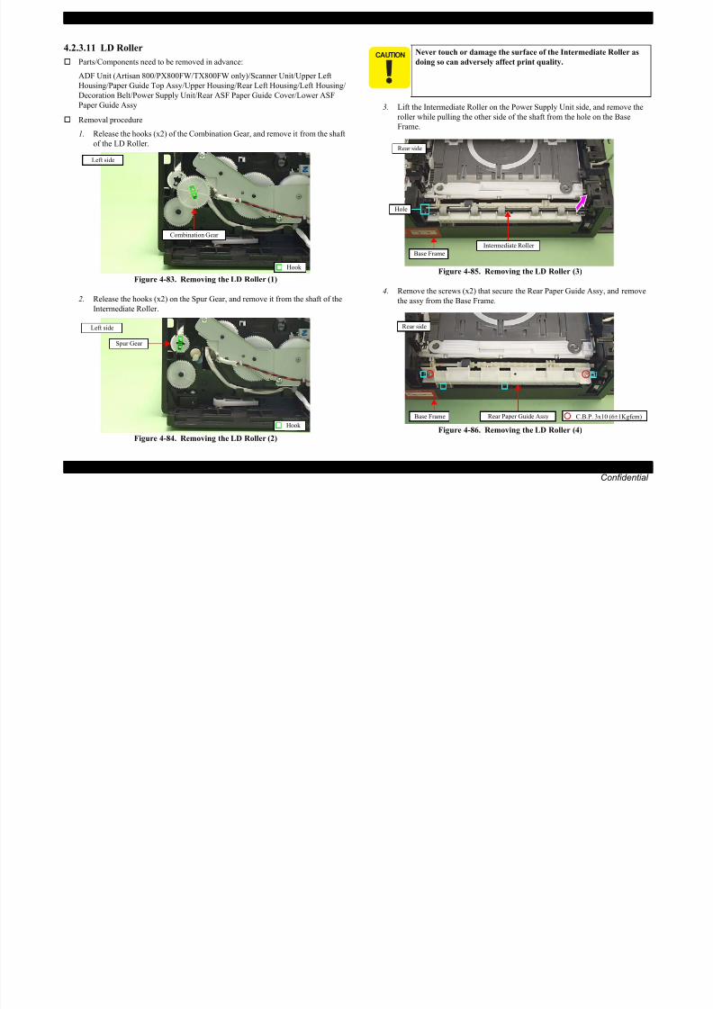
8/22/2019 TX 700 800
http://slidepdf.com/reader/full/tx-700-800 132/234
DISASSEMBLY/ASSEMBLY Disassembly Procedures 132
Confidential
Figure 4-83. Removing the LD Roller (1)
2. Release the hooks (x2) on the Spur Gear, and remove it from the shaft of the
Intermediate Roller.
Figure 4-84. Removing the LD Roller (2)
Figure 4-85. Removing the LD Roller (3)
4. Remove the screws (x2) that secure the Rear Paper Guide Assy, and remove
the assy from the Base Frame.
Figure 4-86. Removing the LD Roller (4)
Hook
Combination Gear
Left side
Spur Gear
Hook
Left side
Intermediate Roller
Base Frame
Hole
C.B.P. 3x10 (6±1Kgfcm)Base Frame Rear Paper Guide Assy
Rear side
EPSON Artisan 800/EPSON Stylus Photo PX800FW/TX800FW/Artisan 700/EPSON Stylus Photo PX700W/TX700W Revision A
5. Slide the LD Roller in the direction of the arrow and pull out the Section A of
the shaft from the Base Frame, then remove the LD Roller by pulling out the
other side of the shaft from the Base Frame.
4.2.3.12 Pick-up Roller
Parts/Components need to be removed in advance:
Cassette Unit
Removal procedure
Never touch or damage the surface of the LD Roller as doing so can
adversely affect print quality.
Rear side
So as to make description easier, the printer in the photographs isplaced vertically in the following steps. Be careful about ink spilling
if the printer is tilted in practical operation.
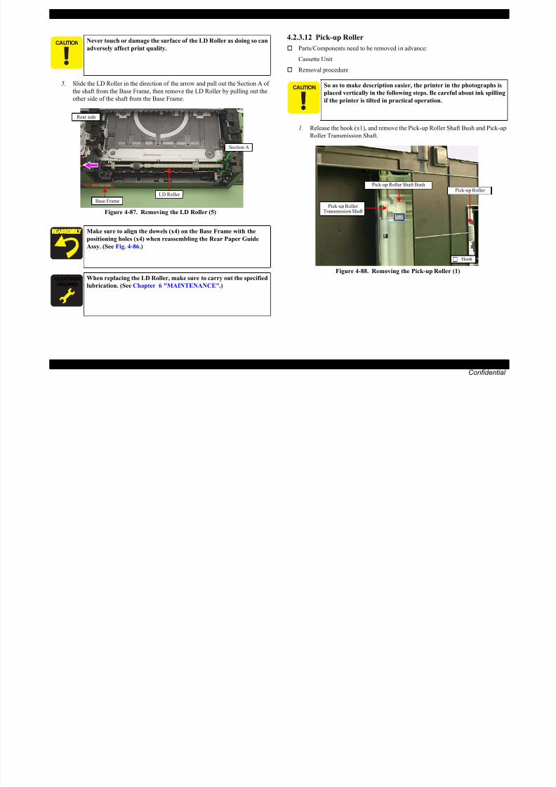
8/22/2019 TX 700 800
http://slidepdf.com/reader/full/tx-700-800 133/234
DISASSEMBLY/ASSEMBLY Disassembly Procedures 133
Confidential
Figure 4-87. Removing the LD Roller (5)
1. Release the hook (x1), and remove the Pick-up Roller Shaft Bush and Pick-up
Roller Transmission Shaft.
Figure 4-88. Removing the Pick-up Roller (1)
Make sure to align the dowels (x4) on the Base Frame with the
positioning holes (x4) when reassembling the Rear Paper Guide
Assy. (See Fig. 4-86.)
When replacing the LD Roller, make sure to carry out the specified
lubrication. (See Chapter 6 "MAINTENANCE".)
Base Frame
LD Roller
Section A
Hook
Pick-up RollerTransmission Shaft
Pick-up Roller Shaft BushPick-up Roller
EPSON Artisan 800/EPSON Stylus Photo PX800FW/TX800FW/Artisan 700/EPSON Stylus Photo PX700W/TX700W Revision A
2. Slide the Pick-up Roller in the direction of the arrow, and remove it.
4.2.3.13 Main Frame
Parts/Components need to be removed in advance:
ADF Unit (Artisan 800/PX800FW/TX800FW only)/Scanner Unit/Upper Left
Housing/Paper Guide Top Assy/Upper Housing/Rear Left Housing/Left Housing/
Decoration Belt/Hinge/Rear Right Housing /Right Housing/Power Supply Unit/
Rear ASF Paper Guide Cover/Lower ASF Paper Guide Assy/CDR Tray/Main
Board/CSIC Assy/Wireless LAN Board /Cartridge Box Unit/Ink Supply TubeAssy/Card Slot Assy/Decompression Pump Unit/Waste Ink Tray Assy
Removal procedure
Be careful not to touch or damage the Pick-up Roller so can
adversely affect print quality.
Since the Main Frame consists of several frames, it may deform
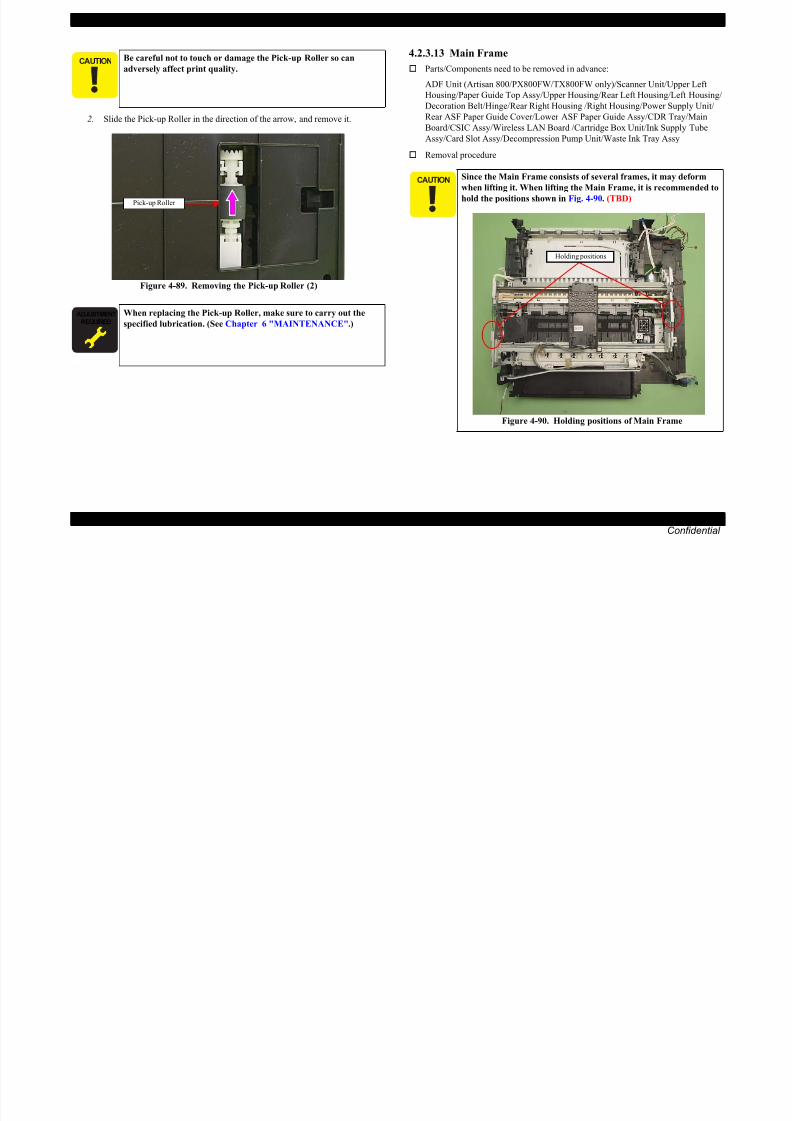
8/22/2019 TX 700 800
http://slidepdf.com/reader/full/tx-700-800 134/234
DISASSEMBLY/ASSEMBLY Disassembly Procedures 134
Confidential
Figure 4-89. Removing the Pick-up Roller (2)
When replacing the Pick-up Roller, make sure to carry out the
specified lubrication. (See Chapter 6 "MAINTENANCE".)
Pick-up Roller
, y
when lifting it. When lifting the Main Frame, it is recommended to
hold the positions shown in Fig. 4-90. (TBD)
Figure 4-90. Holding positions of Main Frame
Holding positions
EPSON Artisan 800/EPSON Stylus Photo PX800FW/TX800FW/Artisan 700/EPSON Stylus Photo PX700W/TX700W Revision A
1. Release the Plunger cable from the hooks (x10) of the Front Frame. (See Fig.
4-91.)
2. Release the PE Sensor cable from the dowel of the Base Frame. (See Fig.
4-91.)
3. Detach the relay connector of the PE Motor cable from the hole of the Base
Frame, and disconnect the connector. (See Fig. 4-91.)4. Remove the Grounding Plate B. (See Fig. 4-92.)
5. Remove the screws (x7) that secure the Main Frame, and remove the Main
Frame from the Base Frame.PE Sensor CableConnector of the PF
Motor Cable
When removing the Main Frame, be careful not to damage the
cables and FFCs with the Main Frame.

8/22/2019 TX 700 800
http://slidepdf.com/reader/full/tx-700-800 135/234
DISASSEMBLY/ASSEMBLY Disassembly Procedures 135
Confidential
Figure 4-91. Removing the Main Frame (1)
Figure 4-92. Removing the Main Frame (2)
Dowel of the Base FrameHole of the Base Frame
Front Frame
Plunger CableHook
5
GroundingPlate A
(Under theFrame)
GroundingPlate B
4
6
7
1
2
3
C.B.P. 3x8 (6±1Kgfcm)
Positioninghole & dowel
EPSON Artisan 800/EPSON Stylus Photo PX800FW/TX800FW/Artisan 700/EPSON Stylus Photo PX700W/TX700W Revision A
4.2.3.14 Front Frame
Parts/Components need to be removed in advance:
Main Frame
Removal procedure
1. Remove the screw (x1) that secures the FFC Holder, and remove the FFC
Attach the Grounding Plate A between the Main Frame and
Base Frame. (See Fig. 4-92, Fig. 4-93.)
When installing the Grounding Plate B, attach the hook of it to
the hole of the Base Frame, and place it over the Main Frame.
(See Fig. 4-92, Fig. 4-93.)
Grounding Plate A
Grounding Plate B
The Main Frame becomes unstable once it is removed from the
Base Frame. Be careful not to deform the frame during
performing the following procedures.
Refer to 4.2.3.13 Main Frame (p134) for the Parts/Components
need to be removed before removing the Main Frame.
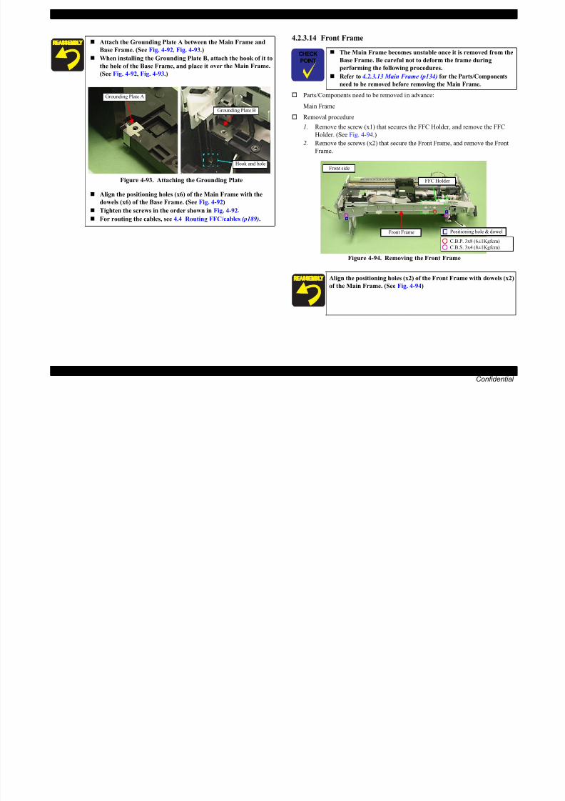
8/22/2019 TX 700 800
http://slidepdf.com/reader/full/tx-700-800 136/234
DISASSEMBLY/ASSEMBLY Disassembly Procedures 136
Confidential
Holder. (See Fig. 4-94.)
2. Remove the screws (x2) that secure the Front Frame, and remove the Front
Frame.
Figure 4-94. Removing the Front Frame
Figure 4-93. Attaching the Grounding Plate
Align the positioning holes (x6) of the Main Frame with the
dowels (x6) of the Base Frame. (See Fig. 4-92)
Tighten the screws in the order shown in Fig. 4-92.
For routing the cables, see 4.4 Routing FFC/cables (p189).
Hook and hole
Align the positioning holes (x2) of the Front Frame with dowels (x2)
of the Main Frame. (See Fig. 4-94)
C.B.S. 3x4 (8±1Kgfcm)
C.B.P. 3x8 (6±1Kgfcm)
Front Frame Positioning hole & dowel
FFC Holder
Front side
EPSON Artisan 800/EPSON Stylus Photo PX800FW/TX800FW/Artisan 700/EPSON Stylus Photo PX700W/TX700W Revision A
4.2.3.15 EJ Frame Assy / EJ Release Frame Assy R/ EJ Release Frame Assy L
Parts/Components need to be removed in advance:
Main Frame/Front Frame
Removal procedure
3. While holding the right side of the EJ Frame Assy, turn the Spur Gear on the
left side in the direction of the arrow, and move the EJ Frame Assy to the front
side.
The Main Frame becomes unstable once it is removed from the
Base Frame. Be careful not to deform the frame during
performing the following procedures.
Refer to 4.2.3.13 Main Frame (p134) for the Parts/Components
need to be removed before removing the Main Frame.
EJ Frame Assy
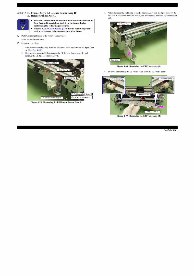
8/22/2019 TX 700 800
http://slidepdf.com/reader/full/tx-700-800 137/234
DISASSEMBLY/ASSEMBLY Disassembly Procedures 137
Confidential
1. Remove the securing ring from the EJ Frame Shaft and remove the Spur Gear
A. (See Fig. 4-95.)
2. Remove the screw (x1) that secures the EJ Release Frame Assy R, and
remove the EJ Release Frame Assy R.
Figure 4-95. Removing the EJ Release Frame Assy R
Figure 4-96. Removing the EJ Frame Assy (1)
4. Pull out and remove the EJ Frame Assy from the EJ Frame Shaft.
Figure 4-97. Removing the EJ Frame Assy (2)
EJ Frame Shaft
Spur Gear A
Securing ring
EJ Release Frame Assy R
Positioning hole & dowel
C.B.S. 3x6 (8±1Kgfcm)
Spur Gear
Grounding springGrounding spring
EJ Frame Shaft
EJ Frame Assy
EPSON Artisan 800/EPSON Stylus Photo PX800FW/TX800FW/Artisan 700/EPSON Stylus Photo PX700W/TX700W Revision A
5. Remove the screw (x1) that secures the EJ Release Frame Assy L and remove
the EJ Release Frame Assy L with the EJ Frame Shaft.
EJ Release Frame Assy L
EJ Frame Shaft
Positioning hole & dowel
After installing the EJ Release Frame Assy L, follow the
procedure below to check the movement of the EJ Release
Trigger.
1. Rotate the EJ Roller counterclockwise as seen from the left
side, and make the EJ Release Trigger stay on the CR
Guide Plate.
2. Lift the CR Guide Plate slightly and push the EJ ReleaseTrigger to the 80 digit side.
3. Make sure to engage the Spur Gear of the EJ Release
Trigger properly with the Combination Gear of the EJ
Release Frame Assy L, and check if the drive force of the
PF Motor transmits up to the EJ Frame Assy.

8/22/2019 TX 700 800
http://slidepdf.com/reader/full/tx-700-800 138/234
DISASSEMBLY/ASSEMBLY Disassembly Procedures 138
Confidential
Figure 4-98. Removing the EJ Release Frame Assy L
Align the dowels (x2) of the EJ Release Frame Assy L with the
positioning holes (x2) of the Main Frame. (See Fig. 4-98.)
Attach the grounding springs (x2) of the EJ Frame Assy onto
the EJ Frame Shaft as shown in Fig. 4-97.
Align the dowel (x1) of the EJ Release Frame Assy R with the
positioning hole (x1) of the Main Frame. (SeeFig. 4-95.)
When attaching the Spur Gear A, insert the protrusion of theEJ Frame Assy to the hole of the Paper Guide Front Assy.
Figure 4-99. Installing the EJ Frame Assy
C.B.S. 3x6 (8±1Kgfcm)
g
Protrusions and holes
EJ Frame Assy
p y
Figure 4-100. Check for EJ Release Trigger movement
After replacing the EJ Frame Assy/EJ Release Frame Assy L/R, be
sure to perform the required lubrication. (See Chapter 6
"MAINTENANCE".)
CR Guide Plate
Combination Gear
Spur Gear
EJ Release Trigger
EJ Release Frame Left Assy
EPSON Artisan 800/EPSON Stylus Photo PX800FW/TX800FW/Artisan 700/EPSON Stylus Photo PX700W/TX700W Revision A
4.2.3.16 PF Motor
Parts/Components need to be removed in advance:
Main Frame
Removal procedure
4. Remove the Tensioner together with the Driven Pulley.
The Main Frame becomes unstable once it is removed from the
Base Frame. Be careful not to deform the frame during
performing the following procedures.
Refer to 4.2.3.13 Main Frame (p134) for the Parts/Components
need to be removed before removing the Main Frame.
Be careful not to touch the PF Scale with bare hands
Driven Pulley
Tensioner
Dowel
ProtrusionTension Holderreinforcing plate

8/22/2019 TX 700 800
http://slidepdf.com/reader/full/tx-700-800 139/234
DISASSEMBLY/ASSEMBLY Disassembly Procedures 139
Confidential
1. Remove the PF Timing Belt. (See 4.2.3.4 PF Scale Step1 (p122).)
2. Remove the screw (x1) that secures the Spacer, and remove the Spacer. (See
Fig. 4-101.)
3. Remove the Compression Spring.
Figure 4-101. Removing the PF Motor (1)
Figure 4-102. Removing the PF Motor (2)
5. Remove the screws (x2) that secure the Tension Holder reinforcing plate and
remove the Holder.
Figure 4-103. Removing the PF Motor (3)
Be careful not to touch the PF Scale with bare hands.
Be careful not to damage or contaminate the PF Scale.
Be careful not to lose the Driven Pulley Shaft.
Left side
C.C.S. 3x6 (9±1Kgfcm)Spacer
Compression Spring
Positioning hole & dowel
Be careful not to damage the Pinion Gear of the PF Motor.
C.P. 3x5 (4±0.5Kgfcm)C.B.S. 3x6 (8±1Kgfcm)
Tension Holder
reinforcing plate
Positioning hole & dowel
EPSON Artisan 800/EPSON Stylus Photo PX800FW/TX800FW/Artisan 700/EPSON Stylus Photo PX700W/TX700W Revision A
6. Remove the screw (x1) that secures the PF Motor, and remove the PF Motor
while drawing out the Pinion Gear from the hole of the Main Frame.4.2.3.17 CR Motor
Parts/Components need to be removed in advance:
Main Frame
Removal procedure
1. Loosen the CR Timing Belt, and detach the CR Timing Belt from the PinionC.P. 3x5 (4±0.5Kgfcm)
Pinion Gear
PF Motor Hole
The Main Frame becomes unstable once it is removed from the
Base Frame. Be careful not to deform the frame during
performing the following procedures.
Refer to 4.2.3.13 Main Frame (p134) for the Parts/Components
need to be removed before removing the Main Frame.

8/22/2019 TX 700 800
http://slidepdf.com/reader/full/tx-700-800 140/234
DISASSEMBLY/ASSEMBLY Disassembly Procedures 140
Confidential
Figure 4-104. Removing the PF Motor (4)Gear of the CR Motor. (See 4.2.3.18 Carriage Unit Step2 - Step4(p143).)
2. Remove the securing ring that secures the Spur Gear A, and remove the Spur
Gears (A, B) and Combination Gear (x1).
Figure 4-106. Removing the CR Motor (1)
When installing the PF Motor, keep the groove of the PF Motorupward.
Figure 4-105. Installing the PF Motor
Align the positioning holes (x2) of the Holder with the dowels
(x2) of the Main Frame. (See Fig. 4-103.)
Insert the Compression Spring to the dowel of the Tensioner
and attach it to the protrusion of the Tension Holder
reinforcing plate. (See Fig. 4-102.) Align the positioning holes (x2) of the Spacer with the dowels
(x2) of the Holder. (See Fig. 4-101.)
After replacing the PF Motor, be sure to perform the required
lubrication. (See Chapter 6 "MAINTENANCE".)
PF Motor
Groove
Spur Gear B
Combination Gear
Spur Gear A
Securing ring
EPSON Artisan 800/EPSON Stylus Photo PX800FW/TX800FW/Artisan 700/EPSON Stylus Photo PX700W/TX700W Revision A
3. Loosen the screw (x1) that secures the Parallelism Bushing. (See Fig. 4-107.)
4. Lift the PG Lever R and disengage the dowel of the Main Frame from the
shaft hole of the Parallelism Bushing. (See Fig. 4-107.)
5. Rotate the Parallelism Bushing till the screw that secures the CR Motor Assy
can be seen.
7. Remove the screws (x2) that secure the CR Motor, and remove the CR Motor
from the CR Motor Holder.
PG Lever R Right side
The screw thatsecures the CR Motor
PG Lever R Right side
Be careful not to damage the Pinion Gear of the CR Motor with the
CR Motor Holder.
CR Motor
CR Motor Holder

8/22/2019 TX 700 800
http://slidepdf.com/reader/full/tx-700-800 141/234
DISASSEMBLY/ASSEMBLY Disassembly Procedures 141
Confidential
Figure 4-107. Removing the CR Motor (2)
6. Remove the screws (x4) that secure the CR Motor, and remove the CR Motor
Assy.
Figure 4-108. Removing the CR Motor (2)
Figure 4-109. Removing the CR Motor (3)
Parallelism Bushing
C.B.S. 3x6 (Secure it after PG Adjustment)
Dowel &shaft hole
Parallelism Bushing
Right side
CR Motor Assy
Positioning hole & dowel
C.B.S. 3x4 (8±1Kgfcm)C.B.S. 3x6 (8±1Kgfcm)
C.P. 3x4 (4±1Kgfcm)
Groove
EPSON Artisan 800/EPSON Stylus Photo PX800FW/TX800FW/Artisan 700/EPSON Stylus Photo PX700W/TX700W Revision A
4.2.3.18 Carriage Unit
Parts/Components need to be removed in advance:
Main Frame/Printhead/CR Scale
Removal procedure
1. Remove the screw (x1) that secures the FFC Holder and remove the FFC
Holder. (See 4.2.3.14 Front Frame Step1 (p136).)
When installing the CR Motor, install it with the groove of the
CR Motor as shown in Fig. 4-109.
Align the dowels (x2) of the CR Motor Holder with the
positioning holes (x2) of the Main Frame. (See Fig. 4-108.)
Phase adjustment of the Spur Gear
• Align the point B of the Spur Gear B with the point C of the
Spur Gear C to make the phases of both gears match.
Spur Gear CSpur Gear B
Carriage Shaft
The Main Frame becomes unstable once it is removed from the
Base Frame. Be careful not to deform the frame during
performing the following procedures.
Refer to 4.2.3.13 Main Frame (p134) for the Parts/Components
need to be removed before removing the Main Frame.

8/22/2019 TX 700 800
http://slidepdf.com/reader/full/tx-700-800 142/234
DISASSEMBLY/ASSEMBLY Disassembly Procedures 142
Confidential
2. Remove the Extension spring 25.63 under the Driven Pulley Assy with
longnose pliers, and remove the Driven Pulley Assy from the Main Frame.
(See Fig. 4-111.)
3. Remove the Driven Pulley from the Driven Pulley Assy, and detach the CR
Timing Belt.
Figure 4-111. Removing the Driven Pulley Assy
Figure 4-110. Aligning the Spur Gear
After replacing the CR Motor, make the specified adjustments.
(See Chapter 5 "ADJUSTMENT".) After replacing the CR Motor, be sure to perform the required
lubrication. (See Chapter 6 "MAINTENANCE".)
Point CPoint B
Carriage Shaft
Be careful not to lose the Driven Pulley Shaft.
Take extra care not to contaminate the CR Timing Belt with
grease on the CR Guide Plate or the Carriage Shaft after
removing the CR Timing Belt from the Main Frame.
Rear sideDriven Pulley Assy
Extension spring 25.63
Driven Pulley AssyCR Timing Belt
Driven Pulley
EPSON Artisan 800/EPSON Stylus Photo PX800FW/TX800FW/Artisan 700/EPSON Stylus Photo PX700W/TX700W Revision A
4. Detach the CR Timing Belt from the CR Motor. 7. Remove the Frame Sheet from the Main Frame.
8. Remove the E-ring and remove the PG Lever R. (See Fig. 4-114.)
9. Remove the Torsion Spring R.Rear side
CR Timing Belt
CR Motor
Right side Torsion Spring R
PG Cam R
E-ring
PG Lever R

8/22/2019 TX 700 800
http://slidepdf.com/reader/full/tx-700-800 143/234
DISASSEMBLY/ASSEMBLY Disassembly Procedures 143
Confidential
Figure 4-112. Removing the CR Timing Belt
5. Remove the screw (x1) that secures the Driven Pulley Timing Assy, and
remove the Driven Pulley Timing Assy. (See Fig. 4-113.)
6. Remove the Driven Pulley from the Driven Pulley Timing Assy, and removethe CR Timing Belt.
Figure 4-113. Removing the Driven Pulley Timing Assy
Figure 4-114. Removing the Carriage Unit (1)
10. Remove the securing ring that secure the PG Cam R and remove the PG Cam
R. (See Fig. 4-117.)
11. Remove the Flat Washer and the Spring Washer.
Figure 4-115. Removing the Carriage Unit (2)
Be careful not to lose the Driven Pulley Shaft.
C.B.P. 3x8 (6±1Kgfcm)
Driven Pulley Timing Assy
Driven PulleyCR Timing Belt
Frame Sheet Rib
Double-sided tape
Edge of Main Frame
PG Lever R
Flat Washer
Spring Washer
Right side Securing ring
PG Cam R
EPSON Artisan 800/EPSON Stylus Photo PX800FW/TX800FW/Artisan 700/EPSON Stylus Photo PX700W/TX700W Revision A
12. Remove the E-ring and remove the PG Lever L. 15. Move the Carriage Unit to the 80 digit side, and lift the Carriage Unit at the
cutout of the CR Guide Plate, and remove the point A on the rear of theCarriage Unit from the CR Guide Plate.
Be careful not to touch the PF Scale with bare hands.
Be careful not to damage or contaminate the PF Scale.
Left side
PG Lever L
Be careful not to damage the Carriage Shaft with the Frame.
Cutout of the CRGuide Plate
Side of the Carriage UnitCarriage Unit

8/22/2019 TX 700 800
http://slidepdf.com/reader/full/tx-700-800 144/234
DISASSEMBLY/ASSEMBLY Disassembly Procedures 144
Confidential
Figure 4-116. Removing the Carriage Unit (3)
13. Removing the Torsion Spring L. (See Fig. 4-117.)
14. Remove the securing ring that secures the PG Cam L and remove the PG Cam
L.
Figure 4-117. Removing the Carriage Unit (4)
Figure 4-118. Removing the Carriage Unit (5)
16. Move the Carriage Unit to the center.
Figure 4-119. Removing the Carriage Unit (6)
E-ring
Rib
Securing ring
PG Cam L
Torsion Spring LLeft side
Carriage Shaft
Point A
CR Guide Plate
Carriage Unit
EPSON Artisan 800/EPSON Stylus Photo PX800FW/TX800FW/Artisan 700/EPSON Stylus Photo PX700W/TX700W Revision A
17. Slide the Carriage Shaft to the 80 digit side, and detach the point B of the
Carriage Shaft from the Main Frame, and remove the Carriage Unit together
with the CR Timing Belt and the Carriage Shaft.
Carriage Unit
Point B
When replacing the CR Timing Belt, insert the CR Timing Belt
to the Timing Belt Holder, and install it to the Carriage Unit as
shown in Fig. 4-121.
Timing Belt Holder Carriage Unit
Insert the area that has teeth on both sides to the groove of the
Timing Belt Holder
Rear side of the Carriage Unit

8/22/2019 TX 700 800
http://slidepdf.com/reader/full/tx-700-800 145/234
DISASSEMBLY/ASSEMBLY Disassembly Procedures 145
Confidential
Figure 4-120. Removing the Carriage Unit (7)
Align the point A on the rear of the Carriage Unit with the
cutout of the CR Guide Plate to install the Carriage Unit. (See
Fig. 4-118.)
When installing the Flat Washer and the Spring Washer, install
them in the order of the Flat Washer and the Spring Washer
from the frame side. (See Fig. 4-115.)
When installing the Torsion Spring R, hook the spring leg
between PG Cam R and the Spring Washer, and attach the
spring to the ribs (x2) of the Main Frame. (See Fig. 4-114, Fig.
4-115.)
When installing the Torsion Spring L, hook the spring leg
between PG Cam L and the Main Frame, and attach it to the
ribs (x2) of the Main Frame. (See Fig. 4-117.)
When installing the Frame Sheet, attach it with double-sided
tape while aligning it with the edge of the Main Frame. (SeeFig. 4-114.)
Carriage Shaft
Figure 4-121. Installing the CR Timing Belt (1)
When installing the Carriage Shaft, align the phase of the Spur
Gear on the 0 digit side. (See Phase adjustment of the Spur Gear
(p142).)
After replacing the Carriage Unit, make the specified
adjustments. (See Chapter 5 "ADJUSTMENT".) After replacing the Carriage Unit, be sure to perform the
required lubrication. (See Chapter 6 "MAINTENANCE".)
C.B.P. 3x8 (6±1Kgfcm)
CR Timing Belt
g
EPSON Artisan 800/EPSON Stylus Photo PX800FW/TX800FW/Artisan 700/EPSON Stylus Photo PX700W/TX700W Revision A
4.2.3.19 Transmission Holder Assy
Parts/Components need to be removed in advance:
Main Frame/Printhead/CR Scale/Carriage Unit/Ink System
Removal procedure
1. Push the Switch Lever in the direction of the arrow and disengage the
Transmission Arm from the Transmission Holder Assy. (See Fig. 4-75, Fig.
The Main Frame becomes unstable once it is removed from the
Base Frame. Be careful not to deform the frame during
performing the following procedures.
Refer to 4.2.3.13 Main Frame (p134) for the Parts/Components
need to be removed before removing the Main Frame.
Make sure that all gears on the Transmission Holder Assy are
properly installed to the hooks and move smoothly.
Hook
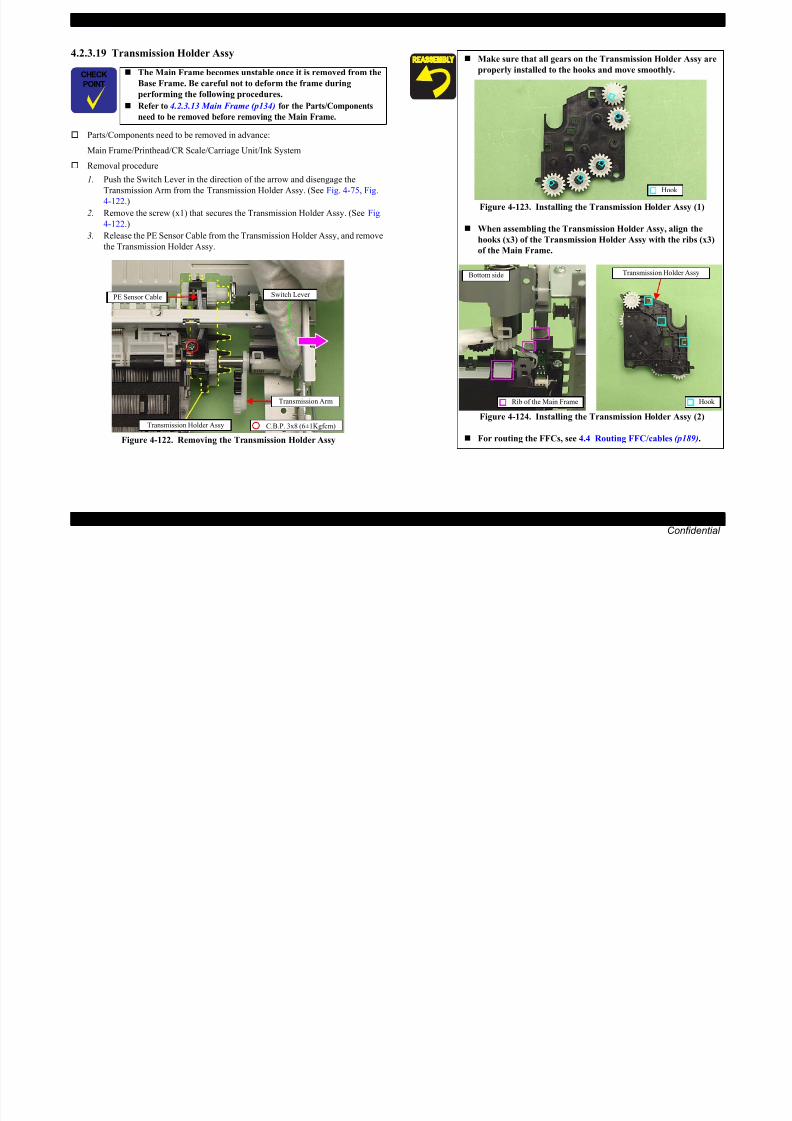
8/22/2019 TX 700 800
http://slidepdf.com/reader/full/tx-700-800 146/234
DISASSEMBLY/ASSEMBLY Disassembly Procedures 146
Confidential
4-122.)
2. Remove the screw (x1) that secures the Transmission Holder Assy. (See Fig.
4-122.)3. Release the PE Sensor Cable from the Transmission Holder Assy, and remove
the Transmission Holder Assy.
Figure 4-122. Removing the Transmission Holder Assy
Switch Lever
Transmission Arm
C.B.P. 3x8 (6±1Kgfcm)Transmission Holder Assy
PE Sensor Cable
Figure 4-123. Installing the Transmission Holder Assy (1)
When assembling the Transmission Holder Assy, align the
hooks (x3) of the Transmission Holder Assy with the ribs (x3)
of the Main Frame.
Figure 4-124. Installing the Transmission Holder Assy (2)
For routing the FFCs, see 4.4 Routing FFC/cables (p189).
Bottom side
Rib of the Main Frame
Transmission Holder Assy
Hook
EPSON Artisan 800/EPSON Stylus Photo PX800FW/TX800FW/Artisan 700/EPSON Stylus Photo PX700W/TX700W Revision A
4.2.3.20 Rear Frame
Parts/Components need to be removed in advance:
Main Frame/Printhead/CR Scale/Carriage Unit/Front Frame/Ink System/
Transmission Holder Assy
Removal procedure
1. Peel off the PF Encoder FFC from the Rear Frame. (See Fig. 4-125.)
4. Remove the screws (x5) that secure the Rear Frame and the screws (x2) that
secure the CR Motor Holder, and remove the Rear Frame together with the
CR Motor Holder. (See Fig. 4-109, Fig. 4-126.)
The Main Frame becomes unstable once it is removed from the
Base Frame. Be careful not to deform the frame during
performing the following procedures.
Refer to 4.2.3.13 Main Frame (p134) for the Parts/Components
need to be removed before removing the Main Frame.
Right side
Front side
Rear Frame

8/22/2019 TX 700 800
http://slidepdf.com/reader/full/tx-700-800 147/234
DISASSEMBLY/ASSEMBLY Disassembly Procedures 147
Confidential
2. Remove the Torsion Spring A (x4), B (x2) and C (x2). (See Fig. 4-125.)
3. Remove the Spur Gears (x2) and Combination Gear (x1). (See 4.2.3.17 CR
Motor Step2 (p140).)
Figure 4-125. Removing the Rear Frame (1)
Figure 4-126. Removing the Rear Frame (2)
Rear side
Double-sided tape
Torsion Spring B
Torsion Spring C
Torsion Spring A
Spur Gear (x2)Combination Gear (x1)
Rear FramePF Encoder FFC
C.B.S. 3x6 (8±1Kgfcm)
Rib & positioning hole
EPSON Artisan 800/EPSON Stylus Photo PX800FW/TX800FW/Artisan 700/EPSON Stylus Photo PX700W/TX700W Revision A
4.2.3.21 Upper Paper Guide L/R / PE Sensor
Parts/Components need to be removed in advance:
Main Frame/Printhead/CR Scale/Carriage Unit/Ink System/Transmission Holder
Assy/Front Frame/Rear Frame/Lower Paper Guide Waste Ink Pad Assy
Removal procedure
Align the ribs (x2) of the Rear Frame with the positioning holes
(x2) of the Main Frame. (See Fig. 4-126.)
Take care of the following points when installing the Torsion
Spring A, B and C.
• Attach the Torsion Spring A (x4) to the ribs of the MainFrame.
•Attach the Torsion Spring B (x2) and C (x2) to the ribs of theRear Frame.
• Align and attach the straight legs of the springs to the groove ofthe Upper Paper Guide L/R.
• Attach the hook-shaped legs to the hooks of the Rear Frame.
ARib of the Rear FrameRib of the Main Frame
The Main Frame becomes unstable once it is removed from the
Base Frame. Be careful not to deform the frame during
performing the following procedures.
Refer to 4.2.3.13 Main Frame (p134) for the Parts/Components
need to be removed before removing the Main Frame.
Be careful not to touch or damage the roller of the Upper Paper

8/22/2019 TX 700 800
http://slidepdf.com/reader/full/tx-700-800 148/234
DISASSEMBLY/ASSEMBLY Disassembly Procedures 148
Confidential
Upper Paper Guide L
1. Release the hooks (x2) of the Main Frame, and remove the Upper Paper
Guide L in the direction of the arrow.
Figure 4-128. Removing the Left Paper Guide
Figure 4-127. Attaching the Torsion Spring
A
B
C
A A A AB B CC
Rear side
Groove of the Upper Paper Guide L/R
Hook of the Rear Frame
g pp p
Guide L/R, or it can adversely affect print quality.
Hook
Rear side
Upper Paper Guide R
EPSON Artisan 800/EPSON Stylus Photo PX800FW/TX800FW/Artisan 700/EPSON Stylus Photo PX700W/TX700W Revision A
Upper Paper Guide R/PE Sensor
1. Remove the screw (x1) that secures the Sub Transmission Cam Holder and
remove the Sub Transmission Cam Holder.
4. Release the hooks (x2) of the Main Frame and remove the Upper Paper Guide
R in the direction of the arrow.
Right side
Hook
Rear side
Upper Paper Guide R

8/22/2019 TX 700 800
http://slidepdf.com/reader/full/tx-700-800 149/234
DISASSEMBLY/ASSEMBLY Disassembly Procedures 149
Confidential
Figure 4-129. Removing the Upper Paper Guide R/PE Sensor
2. Disconnect the PE Sensor cable from the connector. (See Fig. 4-130.)
3. Remove the screw (x1) that secures the PE Sensor, and remove the PE Sensor
avoiding the damage to the Upper Paper Guide sheet.
Figure 4-130. Removing the PE Sensor
Figure 4-131. Removing the Upper Paper Guide R
C.B.S. 3x6 (8±1Kgfcm)
Sub Transmission Cam Holder Positioning hole & dowel
PE Sensor Upper Paper Guide sheet
Connector
PE Sensor cable
Positioning hole & dowel
C.B.P. 3x6 (6±1Kgfcm)
Align the positioning hole of the PE Sensor with the dowel of
the Paper Guide Front Assy. (See Fig. 4-130.)
When installing the PE Sensor, insert the sensor with the Upper
Paper Guide sheet in between. (See Fig. 4-130, Fig. 4-132.)
Figure 4-132. Installing the PE Sensor
PE Sensor
Upper Paper Guide sheet
Upper Paper Guide R
EPSON Artisan 800/EPSON Stylus Photo PX800FW/TX800FW/Artisan 700/EPSON Stylus Photo PX700W/TX700W Revision A
4.2.3.22 Paper Guide Front Assy
Parts/Components need to be removed in advance:
Main Frame/Printhead/CR Scale/Carriage Unit/Ink System/Transmission Holder
Assy/Front Frame/Rear Frame/Lower Paper Guide Waste Ink Pad Assy/Upper
Paper Guide L/Upper Paper Guide R/PE Sensor/EJ Frame Assy/PF Encoder/PF
Scale
Removal procedure
Align the dowels (x2) of the Sub Transmission Cam Holder
with the positioning holes (x2) of the Main Frame. (See Fig.
4-129.)
Align the protrusion of the Transmission Arm with the groove
of the Sub Transmission Cam Holder. (See Fig. 4-133.)
After installing the Sub Transmission Cam Holder, follow the
procedure below to check the movement of the SubTransmission Cam Holder.
1. Slide the switch lever to the 0 digit side to check if the point
A of the Sub Transmission Cam Holder locks the
protrusion of the Transmission Arm, and the arm moves to
the middle.
2. By sliding the switch lever further to the 0 digit side, check
if th l k i l d d th S b T i i C
The Main Frame becomes unstable once it is removed from the
Base Frame. Be careful not to deform the frame during
performing the following procedures.
Refer to 4.2.3.13 Main Frame (p134) for the Parts/Components
need to be removed before removing the Main Frame.

8/22/2019 TX 700 800
http://slidepdf.com/reader/full/tx-700-800 150/234
DISASSEMBLY/ASSEMBLY Disassembly Procedures 150
Confidential
1. Remove the Torsion Springs (x2) and remove the CR Guide Plate.
Figure 4-134. Removing the Paper Guide Front Assy (1)
if the lock is released and the Sub Transmission Cam
Holder returns to the regular position when letting go of
the change lever.
Figure 4-133. Installing the Sub Transmission Cam Holder
Regular position
Protrusion ofTransmission Arm
Switch lever Switch lever
Protrusion ofTransmission Arm
Middle position
Sub Transmission Cam Holder
Groove
Point A
Torsion Spring R
Hook A
Torsion Spring L
Rib
CR Guide Plate
EPSON Artisan 800/EPSON Stylus Photo PX800FW/TX800FW/Artisan 700/EPSON Stylus Photo PX700W/TX700W Revision A
2. Remove the Spur Gear. 4. Remove the screw (x1) that secures the Paper Guide Front Assy. (See Fig.
4-137.)
5. Lift the Paper Guide Front Assy till the point A of Paper Guide Front Assy is
disengaged from the ribs of the Main Frame. (See Fig. 4-137.)
6. Slide the Paper Guide Front Assy to the left till the hooks (x2) on the rear of
the Paper Guide Front Assy are disengaged.
Spur Gear
Left side
Left side Rear side

8/22/2019 TX 700 800
http://slidepdf.com/reader/full/tx-700-800 151/234
DISASSEMBLY/ASSEMBLY Disassembly Procedures 151
Confidential
Figure 4-135. Removing the Paper Guide Front Assy (2)
3. Remove the screw (x1) that secures the Right Front Parallelism Bushing, and
rotate the bushing to make room so that the shaft of the PF Roller can move to
the front side.
Figure 4-136. Removing the Paper Guide Front Assy (3)
Figure 4-137. Removing the Paper Guide Front Assy (4)
Cut Washer 2.1x5.4x0.5C.B.S.(P4) 3x8 (Secure after PG Adjustment)
Right FrontParallel Bush
Right side
Changing point for 0 digitside drive of PF Roller
Right FrontParallel Bush
Right side
Make this roomChanging point for 0 digitside drive of PF Roller
C.B.S. 3x6 (8±1Kgfcm)
Point A& rib Hook
Paper Guide Front Assy
EPSON Artisan 800/EPSON Stylus Photo PX800FW/TX800FW/Artisan 700/EPSON Stylus Photo PX700W/TX700W Revision A
7. Slide the Paper Guide Front Assy to the front till the point A of Paper Guide
Front Assy and the driving force switch section of PF Roller at the 0 digit side
are moved to the opening shown in Fig. 4-138.
8. Slide the Paper Guide Front Assy to the right till the points A of Paper Guide
Front Assy is disengaged from the Main Frame.
Main Frame
Opening
Points A
Leftside
Opening
Rightside
Driving force switch section
of PF Roller at 0 digit side
Install the Paper Guide Front Assy to place the EJ Release
Trigger to the point shown in Fig. 4-140.
Align the protrusion of the Transmission Arm with the hole of
the Main Frame. (See Fig. 4-140.)
Make sure that the Grounding Spring B and C are properly
installed to the Paper Guide Front Assy, and they surely touch
the Main Frame. (See Fig. 4-140.)
B
Protrusion of theTransmission Arm andhole of the Main Frame

8/22/2019 TX 700 800
http://slidepdf.com/reader/full/tx-700-800 152/234
DISASSEMBLY/ASSEMBLY Disassembly Procedures 152
Confidential
Figure 4-138. Removing the Paper Guide Front Assy (5)
9. Lift the left side of the Paper Guide Front Assy and pull the Transmission
Arm from the Main Frame, and remove the Paper Guide Front Assy.
Figure 4-139. Removing the Paper Guide Front Assy (6)
Paper Guide Front Assy
Step 8Step 9
Transmission Arm
Main Frame
Paper Guide Front Assy
Figure 4-140. Installing the Paper Guide Front Assy
Align the hooks (x2) on the rear of the Paper Guide Front Assy.(See Fig. 4-137.)
When installing the Grounding Spring A, hook the Spring leg
to the Main Frame. (See Fig. 4-135.)
When installing the CR Guide Plate, insert the right side of the
CR Guide Plate to the Hook A before attaching it. (See Fig.
4-134.)
When installing the Torsion Spring L/R, hook the Spring leg
over the CR Guide Plate and install it to the ribs (x2) of the
Main Frame. (See Fig. 4-134.)
After replacing the Paper Guide Front, be sure to perform the
required lubrication. (See Chapter 6 "MAINTENANCE".)
Paper Guide Front Assy
EJ Release Trigger
C
Grounding Spring (B,C)
EPSON Artisan 800/EPSON Stylus Photo PX800FW/TX800FW/Artisan 700/EPSON Stylus Photo PX700W/TX700W Revision A
4.2.3.23 Waste Ink Tray Assy
Parts/Components need to be removed in advance:
None
Removal procedure
1. Remove the screw (x1). (See Fig. 4-141.)
2. Insert the flathead screwdriver to the hole of the Rear Right FAX Housing to
l h h k ( 1) d h k A (S i 4 141
3. Remove the Waste Ink Tube from the Waste Ink Cover together with the Tube
Stopper, and remove the Waste Ink Tray Assy. So as to make description easier, the printer in the photographs
is placed vertically in the following steps. Be careful about inkspilling if the printer is tilted in practical operation.
Be careful not to get injured with the sharp edges of the
grounding plate of the Waste Ink Tray Assy.
Be careful about ink spilling from the Waste Ink Tube.
Waste Ink Tube

8/22/2019 TX 700 800
http://slidepdf.com/reader/full/tx-700-800 153/234
DISASSEMBLY/ASSEMBLY Disassembly Procedures 153
Confidential
release the hook (x1), and remove the Waste Ink Tray Assy. (See Fig. 4-141,
Fig. 4-142.)
Figure 4-141. Removing the Waste Ink Tray Assy (1)
Figure 4-142. Removing the Waste Ink Tray Assy (2)Flathead screwdriver
Hook in the hole
C.B.A. 3x10 (6±1Kgfcm)
Sharp edge
Waste Ink Tray Assy
Following the standard below, attach the Tube Stopper to the
Waste Ink Tube, and insert the tube properly to the hole of the
Waste Ink Cover. (See Fig. 4-142, Fig. 4-143.)
Figure 4-143. Attaching the Waste Ink Tube
Tube Stopper
Waste Ink Tray Assy
Waste Ink Cover Hook
47mm
Waste Ink TubeTube Stopper
EPSON Artisan 800/EPSON Stylus Photo PX800FW/TX800FW/Artisan 700/EPSON Stylus Photo PX700W/TX700W Revision A
4.2.3.24 Lower Paper Guide Waste Ink Pad Assy
Parts/Components need to be removed in advance:
Cassette Unit
Removal procedure
1. Release the hooks (x2) and remove the Lower Paper Guide Waste Ink Pad
Assy from the opening at the bottom of the Printer.
Align and insert the ribs (x3) of the Waste Ink Tray Assy to the
holes (x3) of the Base Frame, and secure the assy with the hook
(x1) and screw (x1). (See Fig. 4-141, Fig. 4-142, Fig. 4-144.)
Be careful about ink spilling if the printer is tilted in practical
operation.

8/22/2019 TX 700 800
http://slidepdf.com/reader/full/tx-700-800 154/234
DISASSEMBLY/ASSEMBLY Disassembly Procedures 154
Confidential
Figure 4-145. Removing the Lower Paper Guide Waste Ink Pad Assy
Figure 4-144. Installing the Waste Ink Tray Assy
Rib & holeWaste Ink Tray Assy
Align the ribs (x3) of the Lower Paper Guide Waste Ink Pad Assy
with the holes (x3) of the Main Frame, and secure the assy with the
hooks (x2). (See Fig. 4-145.)
Bottom side
Hook
Rib & hole
Lower Paper GuideWaste Ink Pad Assy
EPSON Artisan 800/EPSON Stylus Photo PX800FW/TX800FW/Artisan 700/EPSON Stylus Photo PX700W/TX700W Revision A
4.2.3.25 Front Paper Guide Waste Ink Pad
Parts/Components need to be removed in advance:
ADF Unit (Artisan 800/PX800FW/TX800FW only)/Scanner Unit/Upper Left
Housing/Paper Guide Top Assy/Upper Housing/Cassette Unit/Lower Paper Guide
Waste Ink Pad Assy
Removal procedure
1. Remove the Front Paper Guide Waste Ink Pad with tweezers.
Front Paper Guide Waste Ink Pad

8/22/2019 TX 700 800
http://slidepdf.com/reader/full/tx-700-800 155/234
DISASSEMBLY/ASSEMBLY Disassembly Procedures 155
Confidential
Figure 4-146. Removing the Front Paper Guide Waste Ink Pad
Install the Front Paper Guide Waste Ink Pad without any gap.
(See Fig. 4-146.)
Insert the Front Paper Guide Waste Ink Pad till the legs (x8) of
Front Paper Guide Waste Ink Pad come out from the Front
Paper Guide.
Figure 4-147. Installing the Front Paper Guide Waste Ink Pad
Legs
Leg of the Front PaperGuide Waste Ink Pad
Bottom
EPSON Artisan 800/EPSON Stylus Photo PX800FW/TX800FW/Artisan 700/EPSON Stylus Photo PX700W/TX700W Revision A
4.2.4 Disassembling Scanner Unit
4.2.4.1 Scanner Upper Housing (Artisan 800/PX800FW/TX800FW)
Parts/Components need to be removed in advance:
Scanner Unit/ADF Unit
R l d
The disassembly/reassembly procedures of Artisan 800/PX800FW/
TX800FW differ from those of Artisan 700/PX700W/TX700W.
(See 4.1.4 Additional Procedure/Procedural Differences (p93).)
Unless otherwise specified, this chapter describes Artisan 800/
PX800FW/TX800FW. Refer to procedures on the flowchart
(Flowchart 4-2 Disassembling Flowchart (2) (p96)) for Artisan 700/PX700W/TX700W.
When installing the Upper Scanner Housing, align the rib of the
Scanner Upper Housing and the groove of the Scanner
Decoration Belt L/R as shown in Fig. 4-149.
When installing the Scanner Decollation Belt L/R, align the
Scanner Lower Housing with the positioning holes and dowels
(Left: x3, Right: x5) of the Scanner Decollation Belt as shown
below.
Right side

8/22/2019 TX 700 800
http://slidepdf.com/reader/full/tx-700-800 156/234
DISASSEMBLY/ASSEMBLY Disassembly Procedures 156
Confidential
Removal procedure
1. Release the screws (x10) that secure the Scanner Upper Housing, and remove
the Scanner Upper Housing.
Figure 4-148. Removing the Scanner Upper Housing
It is recommended to remove the Scanner Upper Housing in a
clean room or on a clean bench to keep away from dust and dirt.
Be careful not to damage the document glass on the Scanner
Upper Housing.
Bottom side
C.B.P. 3x10 (5±1kgfcm)Scanner Upper Housing
Figure 4-149. Installing the Scanner Upper Housing
Left side
Scanner Decoration Belt L
Scanner Upper HousingRib
Groove
Positioning hole anddowel
Scanner Upper Housing
Scanner Decoration Belt R
EPSON Artisan 800/EPSON Stylus Photo PX800FW/TX800FW/Artisan 700/EPSON Stylus Photo PX700W/TX700W Revision A
4.2.4.2 Scanner Motor Unit
Parts/Components need to be removed in advance:
Scanner Unit/ADF Unit/Scanner Upper Housing
Removal procedure
Some of the parts of Artisan 800/PX800FW/TX800FW differ from
those of Artisan 700/PX700W/TX700W. Unless otherwise specified, this section describes the procedures for
Artisan 800/PX800FW/TX800FW. The differences that may affect
the disassembly/reassembly procedures of Artisan 700/PX700W/
TX700W will be provided in “Reassembly”, etc.
Be sure of the following.
Be careful not to touch the Scanner CR Scale with bare hands
When installing the Scanner Motor Unit, be sure of the following.
Route the Scanner Motor cable through the grooves (x3) of the
Scanner Lower Housing. (See Fig. 4-150.)
Align the positioning holes (x3) of the Scanner Motor Unit with
the dowels (x3) of the Scanner Lower Housing. (See Fig. 4-150.)
Route the Grounding Wire as shown below and in Fig. 4-157.
(Artisan 800/PX800FW/TX800FW: Fig. 4-151, Artisan 700/
PX700W/TX700W: Fig. 4-152.)
Artisan 800/PX800FW/TX800FW
GroundingWire

8/22/2019 TX 700 800
http://slidepdf.com/reader/full/tx-700-800 157/234
DISASSEMBLY/ASSEMBLY Disassembly Procedures 157
Confidential
1. Disconnect the Scanner Motor cable from the connector (CN2) on the Scanner
CR Encoder Board.
2. Remove the screws (x3) that secure the Scanner Motor Unit and remove the
Scanner Motor Unit from the Scanner Lower Housing.
Figure 4-150. Removing the Scanner Motor Unit
Be careful not to touch the Scanner CR Scale with bare hands.
Be careful not to damage the Scanner CR Scale.
Scanner Motor Unit
Scanner Motor cable
CN2
Scanner CR Encoder Board C.B.P.,3x8 (5±1kgfcm)
Positioning hole & dowel
Groove
Screw it with theGrounding Wire
Grounding Wire
Figure 4-151. Routing the Grounding Wire
(Artisan 800/PX800FW/TX800FW)
(Continued to the next page.)
Route theGrounding
Wire betweenthe ribs (x5)
and frame.
Rib
Groove
Route the Grounding Wire betweenthe ribs (x2) and frame.Grounding Wire
Grounding Wire
EPSON Artisan 800/EPSON Stylus Photo PX800FW/TX800FW/Artisan 700/EPSON Stylus Photo PX700W/TX700W Revision A
4.2.4.3 Scanner Carriage Unit
Parts/Components need to be removed in advance:
Scanner Unit/ADF Unit/ Scanner Upper Housing/Scanner Motor Unit
Removal procedure
Figure 4-152. Routing the Grounding Wire
(Artisan 700/PX700W/TX700W)
Artisan 700/PX700W/TX700W
Rib
Route the Grounding Wire betweenthe ribs (x5) and frame.
Groove
GroundingWire
Some of the parts of Artisan 800/PX800FW/TX800FW differ from
those of Artisan 700/PX700W/TX700W. Unless otherwise specified, this section describes the procedures for
Artisan 800/PX800FW/TX800FW. The differences that may affect
the disassembly/reassembly procedures of Artisan 700/PX700W/
TX700W will be provided in “Reassembly”, etc.
Be careful no to damage the Rod Lens Array when removing
Scanner Carriage Unit.

8/22/2019 TX 700 800
http://slidepdf.com/reader/full/tx-700-800 158/234
DISASSEMBLY/ASSEMBLY Disassembly Procedures 158
Confidential
Figure 4-153. Handling the Scanner Carriage Unit
Rod Lens Array
EPSON Artisan 800/EPSON Stylus Photo PX800FW/TX800FW/Artisan 700/EPSON Stylus Photo PX700W/TX700W Revision A
1. Release the ribs (Artisan 800/PX800FW/TX800FW: x4, Artisan 700/
PX700W/TX700W: x3) that secure the Scanner Cable Cover to the Scanner
Lower Housing, and remove the Scanner Cable Cover from the Scanner
Lower Housing in the direction of the arrow.
2. Pull out the Ferrite Core from the Scanner Carriage FFC.
3. Turn the Combination Gear 12.1, 11.3 in the direction of the arrow, and move
the Scanner Carriage Unit to the center.
4. Remove the Driven Pulley and Combination Gear12.1, 11.3 from the ScannerLower Housing, and remove the Scanner Timing Belt.
Ferrite CoreScanner Cable Cover
Scanner CarriageFFC
Rear
side
Artisan 800/PX800FW/TX800FW Artisan 700/PX700W/TX700W Rearside
Ferrite Core
Take extra care not to contaminate the Scanner Timing Belt with
grease on the rail of the Lower Scanner Housing.
Scanner Carriage Unit
Driven Pulley Combination Gear12.1, 11.3

8/22/2019 TX 700 800
http://slidepdf.com/reader/full/tx-700-800 159/234
DISASSEMBLY/ASSEMBLY Disassembly Procedures 159
Confidential
Figure 4-154. Removing the Carriage Unit (1)
Figure 4-155. Removing the Scanner Carriage Unit (2)
Scanner Carriage FFCRib
Scanner Timing Belt
y ,
EPSON Artisan 800/EPSON Stylus Photo PX800FW/TX800FW/Artisan 700/EPSON Stylus Photo PX700W/TX700W Revision A
5. Peel off the Scanner Carriage FFC from the Scanner Lower Housing, and
remove the Scanner Carriage Unit.
Be careful not to damage the Scanner Carriage FFC since they are
secured with double-sided tape (x2).
S C i U it
Scanner Carriage FFC
After replacing or removing the Scanner Carriage, be sure to
perform the required lubrication. (See Chapter 6
"MAINTENANCE"(TBD).)

8/22/2019 TX 700 800
http://slidepdf.com/reader/full/tx-700-800 160/234
DISASSEMBLY/ASSEMBLY Disassembly Procedures 160
Confidential
Figure 4-156. Removing the Carriage Unit (3)
When attaching the Scanner Cable Cover, route the FFC and
Grounding Wire as shown below.
Figure 4-157. Attaching the Scanner Cable Cover
Scanner Carriage Unit
Scanner CR Encoder FFC, Cover Open Sensor FFC
Scanner Carriage FFC Grounding WireA
B
C
C
AC
A
BB
Rib
Groove
Rearside
Artisan 800/PX800FW/TX800FW
Artisan 700/PX700W/TX700W
Rearside
EPSON Artisan 800/EPSON Stylus Photo PX800FW/TX800FW/Artisan 700/EPSON Stylus Photo PX700W/TX700W Revision A
4.2.4.4 Scanner CR Encoder Board
Parts/Components need to be removed in advance:
Scanner Unit/ADF Unit/Scanner Upper Housing
Removal procedure
1. Disconnect the Scanner Motor cable from the connector on the Scanner CR
Encoder Board. (See 4.2.4.2 Scanner Motor Unit Step1 (p157).)
2. Disconnect the Scanner CR Encoder FFC from the connector (CN1) on theScanner CR Encoder Board.
3. Loosen the screw that secures the Scanner CR Encoder Board to the Scanner
Lower Housing, and remove Scanner CR Encoder Board from the Scanner
Lower Housing.
Scanner CR Encoder Board
CN1
When routing the Scanner CR Encoder FFC of Artisan 800/
PX800FW/TX800FW, route it as shown in Fig. 4-154 and Fig. 4-158.
See Fig. 4-157 and below for Artisan 700/PX700W/TX700W.
Figure 4-159. Routing the FFC
(Artisan 700/PX700W/TX700W)
Scanner CR Encoder FFC
RibArtisan 700/PX700W/
TX700W
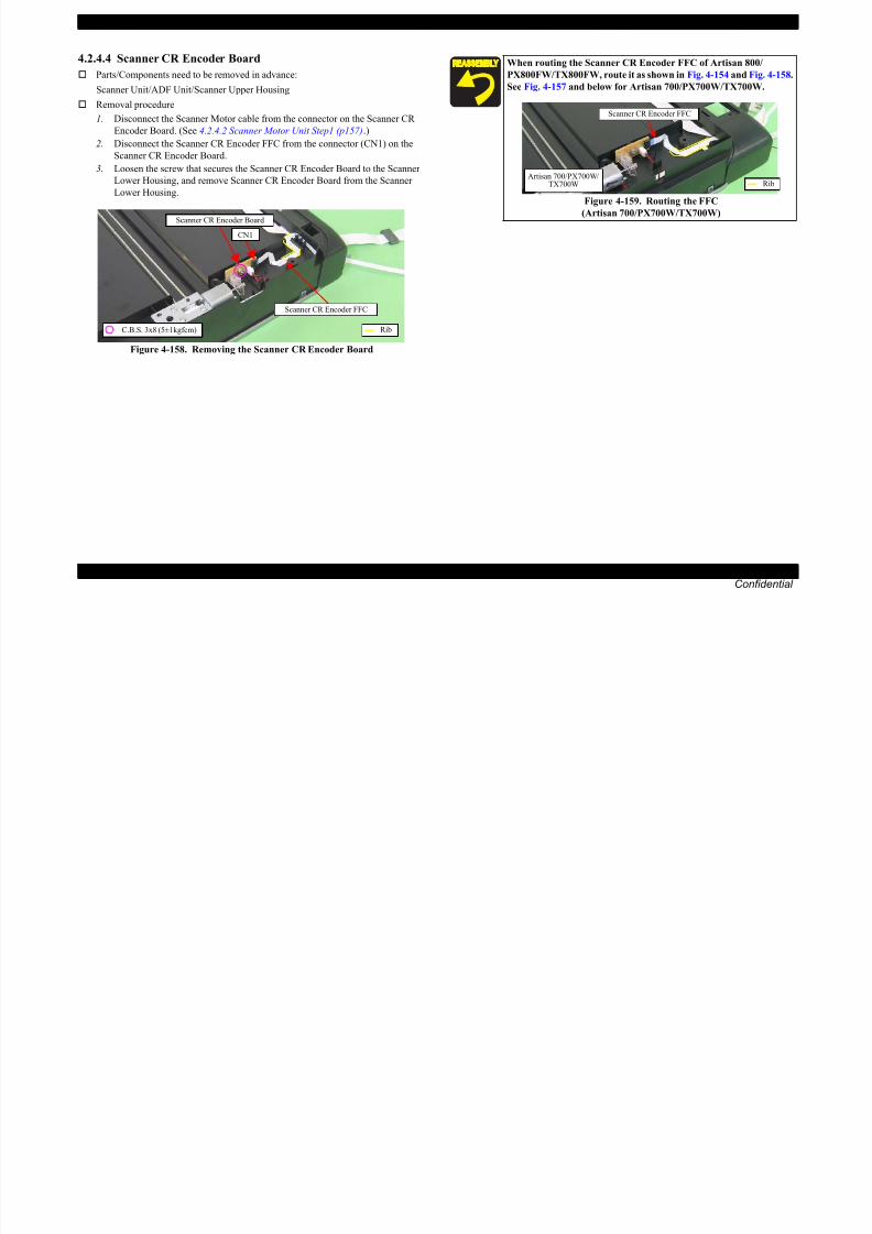
8/22/2019 TX 700 800
http://slidepdf.com/reader/full/tx-700-800 161/234
DISASSEMBLY/ASSEMBLY Disassembly Procedures 161
Confidential
Figure 4-158. Removing the Scanner CR Encoder Board
Scanner CR Encoder FFC
RibC.B.S. 3x8 (5±1kgfcm)
EPSON Artisan 800/EPSON Stylus Photo PX800FW/TX800FW/Artisan 700/EPSON Stylus Photo PX700W/TX700W Revision A
4.2.4.5 Cover Open Sensor
Parts/Components need to be removed in advance:
Scanner Unit/ADF Unit/Scanner Upper Housing
Removal procedure
1. Release the hooks (x2) of the Sensor Cover, and remove the Sensor Cover
from the Scanner Lower Housing.
2. Disconnect the Cover Open Sensor FFC from the connector of the Cover
Open Sensor, and remove the Cover Open Sensor from the Scanner Lower
Housing.
Some of the parts of Artisan 800/PX800FW/TX800FW differ from
those of Artisan 700/PX700W/TX700W. Unless otherwise specified, this section describes the procedures for
Artisan 800/PX800FW/TX800FW. The differences that may affect
the disassembly/reassembly procedures of Artisan 700/PX700W/
TX700W will be provided in “Reassembly”, etc.
Cover Open Sensor
Cover Open Sensor FFC

8/22/2019 TX 700 800
http://slidepdf.com/reader/full/tx-700-800 162/234
DISASSEMBLY/ASSEMBLY Disassembly Procedures 162
Confidential
Figure 4-160. Removing the Cover Open Sensor (1)
Figure 4-161. Removing the Cover Open Sensor (2)
Sensor Cover
Artisan 800/PX800FW/TX800FW
Hook Sensor Cover
Artisan 700/PX700W/TX700W
When attaching the Cover Open Sensor, insert it into the space
inside the ribs (x2) of the Scanner Lower Housing as shown
in Fig. 4-160.
Figure 4-162. Attaching the Cover Open Sensor
Cover Open Sensor
Rib
EPSON Artisan 800/EPSON Stylus Photo PX800FW/TX800FW/Artisan 700/EPSON Stylus Photo PX700W/TX700W Revision A
4.2.5 Disassembly of the ADF Unit (Artisan 800/PX800FW/TX800FW only)
4.2.5.1 ADF Hinge
Parts/Components need to be removed in advance:
Scanner Unit/ADF Unit
Removal procedure
1. Release the guide pins (2 each) that secure the ADF Hinges, and remove the
ADF Hinges from the ADF Base Assy.
When routing the Cover Open Sensor FFC, route it as shown
below and in Fig. 4-157.
Artisan 800/PX800FW/TX800FW
Artisan 700/PX700W/TX700W
Cover Open Sensor FFC
Put FFC through ferrite core, andsecure it with double-sided tape (x7).

8/22/2019 TX 700 800
http://slidepdf.com/reader/full/tx-700-800 163/234
DISASSEMBLY/ASSEMBLY Disassembly Procedures 163
Confidential
Figure 4-164. Removing the ADF Hinge
Figure 4-163. Routing the Cover Open Sensor FFC
RibDouble-sided tape
Cover Open Sensor FFC
Put FFC through ferrite core, andsecure it with double-sided tape (x4).
ADF Hinges
Guide Pin
EPSON Artisan 800/EPSON Stylus Photo PX800FW/TX800FW/Artisan 700/EPSON Stylus Photo PX700W/TX700W Revision A
4.2.5.2 ADF Cover Assy
Parts/Components need to be removed in advance:
Scanner Unit/ADF Unit
Removal procedure
1. Open the ADF Cover Assy.
2. Release the guide pins (x2) that secure the ADF Cover Assy, and remove the
ADF Cover Assy.
4.2.5.3 ADF LD Frame Assy
Parts/Components need to be removed in advance:
Scanner Unit/ADF Unit/ADF Cover Assy
Removal procedure
1. Remove the screws (x4) that secure the ADF LD Frame Assy, and remove the
ADF LD Frame Assy from the ADF Cover Assy.
ADF Cover Assy ADF LD Frame Assy

8/22/2019 TX 700 800
http://slidepdf.com/reader/full/tx-700-800 164/234
DISASSEMBLY/ASSEMBLY Disassembly Procedures 164
Confidential
Figure 4-165. Removing the ADF Cover AssyFigure 4-166. Removing the ADF LD Frame Assy
Guide Pin
When installing the ADF LD Frame Assy, align the dowels(x4) of
the ADF Cover Assy with the positioning holes (x4) of the ADF LD
Frame Assy as shown in Fig. 4-166.
C.B.P. 3x8 (6±1kgfcm)
Positioning hole & dowel
EPSON Artisan 800/EPSON Stylus Photo PX800FW/TX800FW/Artisan 700/EPSON Stylus Photo PX700W/TX700W Revision A
4.2.5.4 ADF Right Cover/ADF Rear Cover
Parts/Components need to be removed in advance:
Scanner Unit/ADF Unit/ADF Cover Assy
Removal procedure
1. Release the hooks (x3) that secure the ADF Right Cover, and remove the
ADF Right Cover from the ADF Base Assy.
2. Open the ADF Document Support Cover.
3. Remove the screws (x3) that secure the ADF Rear Cover.
4. Release the hooks (x11) that secure the ADF Rear Cover, and remove the
ADF Rear Cover from the ADF Base Assy.
ADF Right Cover
ADF Base Assy
ADF Document Support Cover

8/22/2019 TX 700 800
http://slidepdf.com/reader/full/tx-700-800 165/234
DISASSEMBLY/ASSEMBLY Disassembly Procedures 165
Confidential
Figure 4-167. Removing the ADF Right Cover
Figure 4-168. Removing the ADF Rear CoverHook
Bottom side
Rib
ADF Rear Cover C.B.P. 2.5x6 (black) (6±1kgfcm)
Hook
C.B.P. 2.5x6 (6±1kgfcm)
EPSON Artisan 800/EPSON Stylus Photo PX800FW/TX800FW/Artisan 700/EPSON Stylus Photo PX700W/TX700W Revision A
4.2.5.5 ADF Cover Stacker/ADF Document Support Cover
Parts/Components need to be removed in advance:
Scanner Unit/ADF Unit/ADF Cover Assy/ADF Right Cover/ADF Rear Cover
Removal procedure
1. Release the dowels (x2) that secure the ADF Cover Stacker, and remove the
ADF Cover Stacker from the ADF Base Assy.
When installing the ADF Right Cover, align the positioning
holes (x2) with the dowels (x2) of the ADF Right Cover and the
ADF Base Assy, and also align the ribs (x6) shown in Fig. 4-167.
Figure 4-169. Installing the ADF Right Cover
When installing the ADF Rear Cover align the ribs with the
Positioning hole& dowelADF Right Cover
ADF Cover Stacker Protrusions of the ADFDocument Support Cover

8/22/2019 TX 700 800
http://slidepdf.com/reader/full/tx-700-800 166/234
DISASSEMBLY/ASSEMBLY Disassembly Procedures 166
Confidential
Figure 4-171. Removing the ADF Cover Stacker
When installing the ADF Rear Cover, align the ribs with the
grooves (x3) as shown below.
Figure 4-170. Installing the ADF Rear Cover
Rib & GrooveADF Rear Cover Dowel
ADF Base Assy
EPSON Artisan 800/EPSON Stylus Photo PX800FW/TX800FW/Artisan 700/EPSON Stylus Photo PX700W/TX700W Revision A
2. Release the dowels (x2) that secure the ADF Document Support Cover, and
remove the ADF Document Support Cover from the ADF Base Assy.4.2.5.6 ADF Front Cover
Parts/Components need to be removed in advance:
Scanner Unit/ADF Unit/ADF Cover Assy/ADF Right Cover A/DF Rear Cover/
ADF Cover Stacker/ADF Document Support Cover
Removal procedure
1. Remove the screws (x2) that secure the ADF Front Cover.
2. Release the ribs (x4) of the ADF Base Assy from the ADF Front Cover and
remove the ADF Front Cover from the ADF Base Assy.
ADF Document Support Cover
When removing the ADF Front Cover, be careful not to damage thepositioning holes (x4) of the ADF Front Cover shown in Fig. 4-173.

8/22/2019 TX 700 800
http://slidepdf.com/reader/full/tx-700-800 167/234
DISASSEMBLY/ASSEMBLY Disassembly Procedures 167
Confidential
Figure 4-172. Removing the ADF Document Support Cover
Figure 4-173. Removing the ADF Front Cover
When installing the ADF Cover Stacker, insert the protrusions (x2)
of the ADF Document Support Cover under the ADF Cover Stackeras shown in Fig. 4-171.
Dowel
ADF Base Assy
ADF Front Cover
ADF Front Cover
C.B.P. 2.5x6 (black) (6±1kgfcm)
Rib
C.B.P. 2.5x6 (6±1kgfcm)
ADF Base Assy
Positioning hole
EPSON Artisan 800/EPSON Stylus Photo PX800FW/TX800FW/Artisan 700/EPSON Stylus Photo PX700W/TX700W Revision A
4.2.5.7 ADF Document Support Assy
Parts/Components need to be removed in advance:
Scanner Unit/ADF Unit/ADF Cover Assy/ADF Right Cover/ADF Rear Cover/
ADF Cover Stacker/ADF Document Support Cover/ADF Front Cover
Removal procedure
1. Release the hooks (x2) that secure the ADF Document Support Assy.
2. Release the dowels (x2) that secure the ADF Document Support Assy, andremove the ADF Document Support Assy from the ADF Base Assy.
4.2.5.8 ADF Frame Unit
Parts/Components need to be removed in advance:
Scanner Unit/ADF Unit/ADF Cover Assy/ADF Right Cover/ADF Rear Cover/
ADF Cover Stacker/ADF Document Support Cover/ADF Front Cover/ADF
Document Support Assy
Removal procedure
1. Peel off the acetate tape (x2), and release the cable of the ADF Unit from theADF Base Assy.
ADF Document Support AssyADF Frame Unit
ADF Base Assy
Acetate tapes

8/22/2019 TX 700 800
http://slidepdf.com/reader/full/tx-700-800 168/234
DISASSEMBLY/ASSEMBLY Disassembly Procedures 168
Confidential
Figure 4-174. Removing the ADF Document Support Assy
Figure 4-175. Removing the ADF Frame Unit (1)
Dowel Hook
ADF Base AssyGroove
Cable of the ADF Unit
ADF Cable Cover
EPSON Artisan 800/EPSON Stylus Photo PX800FW/TX800FW/Artisan 700/EPSON Stylus Photo PX700W/TX700W Revision A
2. Remove the screws (x2) that secure the ADF Frame Unit.
3. Release the dowel (x1) of the ADF Base and the dowels (x2) of the
ADF Frame Unit, then remove the ADF Frame Unit from the ADF Base Assy.
4.2.5.9 ADF Motor Unit
Parts/Components need to be removed in advance:
Scanner Unit/ADF Unit/ADF Cover Assy/ADF Right Cover/ADF Rear Cover/
ADF Cover Stacker/ADF Document Support Cover/ADF Front Cover/ADF
Document Support Assy/ADF Frame Unit
Removal procedure
1. Peel off the acetate tape (x3), and separate the ADF Motor cable, the ADFSensor cable and the Grounding Wire.
2. Release the hooks (x4) of the ADF Cable Cover and open the ADF Cable
Cover, then release the ADF Motor cable, the ADF Sensor cable and the
Grounding Wire.ADF Frame Unit
ADF Cable Cover Acetate tape

8/22/2019 TX 700 800
http://slidepdf.com/reader/full/tx-700-800 169/234
DISASSEMBLY/ASSEMBLY Disassembly Procedures 169
Confidential
Figure 4-176. Removing the ADF Frame Unit (2)
Figure 4-177. Releasing the cables When installing the ADF Frame Unit, align the positioning
holes (x3) of the ADF Frame Unit and ADF Base Assy with the
dowels (x3) as shown in Fig. 4-176.
Route the ADF Motor cable, ADF Sensor cable, and the
Grounding Wire as follows, referring to Fig. 4-175.
1. Route them through the grooves (x3) of the ADF Base Assy.
2. Attach the ADF Cable Cover to the ADF Base Assy.3. Secure the cables to the ADF Base Assy with acetate tape
(x2).
C.B.P. 3x8 (6±1kgfcm)
ADF Base Assy
Positioning hole & dowel
Hook
Acetate tapes (x2)
ADF Sensor cable
Grounding Wire
ADF Motor cable
EPSON Artisan 800/EPSON Stylus Photo PX800FW/TX800FW/Artisan 700/EPSON Stylus Photo PX700W/TX700W Revision A
3. Remove the screws (x2) that secure the ADF Motor Unit.
4. Remove the screw (x1), and remove the torsion spring and the Grounding
Wire from the ADF Motor Unit, then remove the ADF Motor Unit from the
ADF Frame Unit.
When removing the ADF Motor Unit, be careful not to drop the
gears (x5) of the ADF Frame Unit and ADF Motor Unit shown
below.
Figure 4-178. Handling the ADF Motor Unit
ADF Frame Unit Do not drop these.
Do not drop these.
Torsion spring
Shafts & holes
ADF Frame Unit
ADF Motor Unit
C.B.P. 3x8 (6±1kgfcm)
Grounding Wire

8/22/2019 TX 700 800
http://slidepdf.com/reader/full/tx-700-800 170/234
DISASSEMBLY/ASSEMBLY Disassembly Procedures 170
Confidential
Figure 4-179. Removing the ADF Motor Unit (1)
Figure 4-180. Removing the ADF Motor Unit (2)
ADF Motor Unit
C.B.P. 3x8 (6±1kgfcm)
EPSON Artisan 800/EPSON Stylus Photo PX800FW/TX800FW/Artisan 700/EPSON Stylus Photo PX700W/TX700W Revision A
Be careful of the following when installing the ADF Motor Unit.
Route the ADF Motor cable, the ADF Sensor cable and the
Grounding Wire as shown below.
Fi 4 181 R ti th bl
ADF Sensor cable
ADF Motor cable
Grounding Wire
ADF Motor Unit
When placing the cables on the ADF Cable Cover, route them
as shown below.
ADF Cable Cover
ADF Sensor cable
ADF Motor cable
Align the edge of theacetate tape to the edge
of the ADF Cable Cover.
Grounding Wire
Acetate tape

8/22/2019 TX 700 800
http://slidepdf.com/reader/full/tx-700-800 171/234
DISASSEMBLY/ASSEMBLY Disassembly Procedures 171
Confidential
Figure 4-181. Routing the cables
Attach the torsion spring from under the ADF EJ Roller.
Figure 4-182. Attaching the torsion spring
Insert the shaft of the ADF Motor Unit to the hole of the ADF
Frame Unit as shown in Fig. 4-180.
ADF EJ Roller
Torsion spring
Figure 4-183. Routing the cables in the ADF Cable Cover
EPSON Artisan 800/EPSON Stylus Photo PX800FW/TX800FW/Artisan 700/EPSON Stylus Photo PX700W/TX700W Revision A
4.2.5.10 ADF PF Roller
Parts/Components need to be removed in advance:
Scanner Unit/ADF Unit/ADF Cover Assy/ADF Right Cover/ADF Rear Cover/
ADF Cover Stacker/ADF Document Support Cover/ADF Front Cover/ADF
Document Support Assy/ADF Frame Unit
Removal procedure
1. Remove the Spur Gear 6.4, securing ring and the ADF EJ Rear Bush from theADF PF Roller.
3. Remove the E-ring.
4. Remove the torsion spring from the ADF PF Roller, and remove the ADF PF
Roller from the ADF Frame Unit in the direction of the arrow.
ADF PF Roller

8/22/2019 TX 700 800
http://slidepdf.com/reader/full/tx-700-800 172/234
DISASSEMBLY/ASSEMBLY Disassembly Procedures 172
Confidential
Figure 4-184. Removing the ADF PF Roller (1)
2. Release the hooks (x2) and remove the ADF EJ Front Bush from the ADF
Frame Unit.
Figure 4-185. Removing the ADF PF Roller (2)
Figure 4-186. Removing the ADF PF Roller (3)
ADF PF Roller
ADF EJ Rear Bush
Securing ringSpur Gear 6.4
ADF EJ Front Bush
Hook
When installing the ADF PF Roller, attach the leg of the torsion
spring on the ADF PF Roller as shown in Fig. 4-186.
After replacing or removing the ADF PF Roller, be sure to perform
the required lubrication. (See Chapter 6 "MAINTENANCE".)
E-ringTorsion spring
EPSON Artisan 800/EPSON Stylus Photo PX800FW/TX800FW/Artisan 700/EPSON Stylus Photo PX700W/TX700W Revision A
4.3 Disassembly/reassembly procedures specificto Artisan 700/PX700W/TX700W
4.3.1 Removing the Housing
4.3.1.1 Scanner Unit (Artisan 700/PX700W/TX700W)
Parts/Components need to be removed in advance:
None
Removal procedure
1. Open the Scanner Unit.
4. Peel off the Scanner FFC (x3) together with the Ferrite core (x1) from the
Main Board.
5. Pull out the terminal of the Grounding Wire from the Frame.
The disassembly/reassembly procedures for Artisan 800/PX800FW/
TX800FW differ from those of Artisan 700/PX700W/TX700W, see
4.2.1.2 Scanner Unit (p98) for the procedures.
f i
Scanner FFC
Main Board
Grounding Wire
Terminal of theGrounding Wire
Ferrite core

8/22/2019 TX 700 800
http://slidepdf.com/reader/full/tx-700-800 173/234
DISASSEMBLY/ASSEMBLY Disassembly/reassembly procedures specific to Artisan 700/PX700W/TX700W 173
Confidential
2. Cut the fastener with a nipper as shown in Fig. 4-187, and remove the Cable
Cover.
3. Slide the Cable Cover to the rear of the printer by pushing the point A of the Cable
Cover to release the hooks (x4) and ribs (x2), and remove the Cable Cover.
Figure 4-187. Removing the Cable Cover
Figure 4-188. Removing the Scanner Unit (1)
6. Remove the screw (x1) that secures the Scanner Unit.
Figure 4-189. Removing the Scanner Unit (2)
The fastener needs to be cut when removing and cannot be reused.
When installing the Cable Cover, replace it with a new one. (See Fig.
4-1)
Fastener
Cable Cover
Right inside
Point A
Hook
Fastener
Cutting position
Cross-section
Do not open/close the Scanner Unit with the screws that secure the
unit removed to avoid damage of the Scanner Unit Hinge.
Rear side
C.B.P. 3x10 (black) (6±1Kgfcm)
EPSON Artisan 800/EPSON Stylus Photo PX800FW/TX800FW/Artisan 700/EPSON Stylus Photo PX700W/TX700W Revision A
7. Lift the Hinge on the right side in the direction of the arrow (1), and slide the
Scanner Unit in the direction of the arrow (2), and remove it.
Scanner Unit
1
2
When installing the Scanner Unit, follow the procedure below.
1. Align and insert the dowel of the Scanner Unit to the
positioning hole of the printer (Left inside).
2. Align and insert the rib of the Scanner Unit to the groove of
the Hinge.
Hole
Dowel
Left
inside
Rib of the Scanner Unit
& groove of the Hinge
Right
inside

8/22/2019 TX 700 800
http://slidepdf.com/reader/full/tx-700-800 174/234
DISASSEMBLY/ASSEMBLY Disassembly/reassembly procedures specific to Artisan 700/PX700W/TX700W 174
Confidential
Figure 4-190. Removing the Scanner Unit (3)
Figure 4-191. Installing the Scanner Unit
Make sure to insert the terminal of the Grounding wire to the
fixing rib of the frame. (See Fig. 4-188.)
For the routing the FFCs, see 4.4 Routing FFC/cables (p189).
EPSON Artisan 800/EPSON Stylus Photo PX800FW/TX800FW/Artisan 700/EPSON Stylus Photo PX700W/TX700W Revision A
4.3.1.2 Upper Left Housing (Artisan 700/PX700W/TX700W)
Parts/Components need to be removed in advance:
None
Removal procedure
1. Remove the screw (x1) that secures the Upper Left Housing.
2. Slide the Upper Left Housing to the rear side, release the hooks (x2) and
remove the Upper Left Housing.
4.3.1.3 Upper Housing (Artisan 700/PX700W/TX700W)
Parts/Components need to be removed in advance:
Scanner Unit/Upper Left Housing/Paper Guide Top Assy
Removal procedure
The disassembly/reassembly procedures for Artisan 800/PX800FW/
TX800FW differ from those of Artisan 700/PX700W/TX700W, see
4.2.1.4 Upper Left Housing / Panel Lock Button (p100) for the
procedures.
The disassembly/reassembly procedures for Artisan 800/PX800FW/
TX800FW differ from those of Artisan 700/PX700W/TX700W, see
4.2.1.5 Upper Housing (p101) for the procedures.
The Grounding Wire is attached to the frame with a screw. Be
careful not to deform the frame when removing the screw.

8/22/2019 TX 700 800
http://slidepdf.com/reader/full/tx-700-800 175/234
DISASSEMBLY/ASSEMBLY Disassembly/reassembly procedures specific to Artisan 700/PX700W/TX700W 175
Confidential
Figure 4-192. Removing the Upper Left Housing
1. Remove the screw (x1) and release the Grounding Wire.
Figure 4-193. Releasing the Grounding WireC.B.P. 3x10 (black) (6±1Kgfcm)
Upper Left Housing
Hook C.B.S. 3x6 (8±1Kgfcm)
GroundingWire
EPSON Artisan 800/EPSON Stylus Photo PX800FW/TX800FW/Artisan 700/EPSON Stylus Photo PX700W/TX700W Revision A
2. Release the hooks (x5) of the Panel Unit Front Cover. (See Fig. 4-194)
3. While pushing the Panel Lock Button, slide the Panel Upper Cover in the
direction of the arrow to release the hook (x8) of the Panel Upper Cover, and
remove the Panel Upper Cover.
4. Remove the screws (x10) that secure the Upper Housing.
Panel Unit Front Cover
Panel Unit
Panel Upper Cover
1
2
3
4
5
7
8
6Upper Housing
9
10

8/22/2019 TX 700 800
http://slidepdf.com/reader/full/tx-700-800 176/234
DISASSEMBLY/ASSEMBLY Disassembly/reassembly procedures specific to Artisan 700/PX700W/TX700W 176
Confidential
Figure 4-194. Removing the Upper Housing (1)
Figure 4-195. Removing the Upper Housing (2)
5. Open the Panel Unit, and lift the Panel Unit until the screw (x1) can be seen
from under the Right Hinge, and then remove the screw (x1).
Figure 4-196. Removing the Upper Housing (3)
Panel Lock Button
Hook of the Panel Upper Cover Hook of the Panel Unit Front Cover
C.B.S. 3x6 (8±1Kgfcm)C.B.S. 3x8 (black) (8±1Kgfcm)
C.B.P. 3x10 (6±1Kgfcm)C.B.A. 3x6 (black) (6±1Kgfcm)
C.B.P. 3x10 (black) (6±1Kgfcm)
Panel Unit
Right Hinge
C.B.P. 3x12 (black) (6+1Kgfcm)
EPSON Artisan 800/EPSON Stylus Photo PX800FW/TX800FW/Artisan 700/EPSON Stylus Photo PX700W/TX700W Revision A
6. Peel off the double-sided tape A that secures the Panel FFC to the Front
Frame, and lift the Upper Housing until the Panel FFC becomes detached
from the FFC Holder. (See Fig. 4-197.)
7. Peel off the double-sided tape B that secures the Panel FFC to the Panel Unit.
(See Fig. 4-197.)
8. Disconnect the Panel FFC from the connector on the Panel Unit, and remove
the Upper Housing together with the Panel Unit.
4.3.1.4 Rear Left Housing (Artisan 700/PX700W/TX700W)
Parts/Components need to be removed in advance:
Scanner Unit/Upper Left Housing/Paper Guide Top Assy/Upper Housing
Removal procedure
1. Remove the screws (x2) that secure the Rear Left Housing, and remove the
Rear Left Housing.Panel FFC
FrontFrame
Double-sidedtape A
Panel Unit
Upper Housing
Double-sided tape A
Double-sided tape B
The disassembly/reassembly procedures for Artisan 800/PX800FW/
TX800FW differ from those of Artisan 700/PX700W/TX700W, see
4.2.1.6 Rear Left Housing (p103) for the procedures.

8/22/2019 TX 700 800
http://slidepdf.com/reader/full/tx-700-800 177/234
DISASSEMBLY/ASSEMBLY Disassembly/reassembly procedures specific to Artisan 700/PX700W/TX700W 177
Confidential
Figure 4-197. Removing the Upper Housing (4)
9. Remove the Panel Unit from the Upper Housing. (See 4.3.2.1 Panel Unit
(Artisan 700/PX700W/TX700W) (p181).)
Figure 4-199. Removing the Rear Left Housing
Tighten the screws in the order indicated in Fig. 4-195.
Secure the Panel FFC with double-sided tape to the Front
Frame. (See Fig. 4-197.)
Secure the Panel FFC to the Panel Unit with double-sided tape.
Figure 4-198. Installing the Upper Housing
FFC Holder Panel FFC
Panel FFC Double-sided tape
When installing the Rear Left Housing, insert the ribs (x2) of the
Rear Left Housing to the inside of the Left Housing. (See Fig.
4-199.)
C.B.A. 3x6 (black) (6±1Kgfcm)
Rib
Left Housing
Rear Left Housing
EPSON Artisan 800/EPSON Stylus Photo PX800FW/TX800FW/Artisan 700/EPSON Stylus Photo PX700W/TX700W Revision A
4.3.1.5 Left Housing/Decoration Belt L (Artisan 700/PX700W/TX700W)
Parts/Components need to be removed in advance:
Scanner Unit/Upper Left Housing/Paper Guide Top Assy/Upper Housing/Rear
Left Housing
Removal procedure
1. Remove the Decoration Belt.
2. Remove the screws (x2) that secure the Left Housing.
3. Release the hooks (x3) on the bottom and dowel (x1) on the front side of the
Left Housing, and remove the Left Housing in the direction of the arrow.
The disassembly/reassembly procedures for Artisan 800/PX800FW/
TX800FW differ from those of Artisan 700/PX700W/TX700W, see
4.2.1.7 Left Housing / Decoration Belt L (p104) for the procedures.
So as to make description easier, the printer in the photographs is
placed vertically in the following steps. Be careful about ink spilling
if the printer is tilted in practical operation.
Left Housing
Positioning hole& dowel

8/22/2019 TX 700 800
http://slidepdf.com/reader/full/tx-700-800 178/234
DISASSEMBLY/ASSEMBLY Disassembly/reassembly procedures specific to Artisan 700/PX700W/TX700W 178Confidential
Figure 4-200. Removing the Left Housing/Decoration Belt L (1)
Figure 4-201. Removing the Left Housing/Decoration Belt L (2)
C.B.A. 3x6 (black)(6±1Kgfcm)C.B.P. 3x10 (6±1Kgfcm)
Decoration Belt
Left Housing
Align and insert the rib in the front inside of the Left Housing to
the inside of the rib of the Base Frame.
Figure 4-202. Installing the Left Housing
Align the positioning hole of the Left Housing with the dowel of
the Base Frame. (See Fig. 4-201.)
Hook
The ribs of LeftHousing and the BaseFrame are inside.
Rib of the Base Frame
Rib of the Left Housing
EPSON Artisan 800/EPSON Stylus Photo PX800FW/TX800FW/Artisan 700/EPSON Stylus Photo PX700W/TX700W Revision A
4.3.1.6 Rear Right Housing (Artisan 700/PX700W/TX700W)
Parts/Components need to be removed in advance:
Scanner Unit/Upper Left Housing/Paper Guide Top Assy/Upper Housing/Hinge
Removal procedure
1. Remove the screw (x1) that secures the Rear Right Housing.
2. Release the ribs (x2) on the right side, and also release the point A, then
remove the Rear Right Housing by lifting it in the direction of the arrow. (See
Fig. 4-203.)
The disassembly/reassembly procedures for Artisan 800/PX800FW/
TX800FW differ from those of Artisan 700/PX700W/TX700W, see
4.2.1.10 Rear Right FAX Housing (p106) for the procedures.
Right Housing
Point A
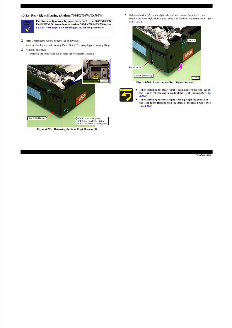
8/22/2019 TX 700 800
http://slidepdf.com/reader/full/tx-700-800 179/234
DISASSEMBLY/ASSEMBLY Disassembly/reassembly procedures specific to Artisan 700/PX700W/TX700W 179Confidential
Figure 4-203. Removing the Rear Right Housing (1)
Figure 4-204. Removing the Rear Right Housing (2)
l
C.B.A. 3x10 (black) (6±1Kgfcm)
C.B.S. 3x6 (black) (8±1Kgfcm)C.B.P. 3x10 (6±1Kgfcm)
Hook A
Rear Right Housing
When installing the Rear Right Housing, insert the ribs (x2) of
the Rear Right Housing to inside of the Right Housing. (See Fig.
4-204.)
When installing the Rear Right Housing, align the point A of
the Rear Right Housing with the inside of the Base Frame. (See
Fig. 4-204.)
RibRear Right Housing
EPSON Artisan 800/EPSON Stylus Photo PX800FW/TX800FW/Artisan 700/EPSON Stylus Photo PX700W/TX700W Revision A
4.3.1.7 Right Housing/Card Cover (Artisan 700/PX700W/TX700W)
Parts/Components need to be removed in advance:
Scanner Unit/Upper Left Housing/Paper Guide Top Assy/Upper Housing/Hinge/
Rear Right Housing
Removal procedure
1. Remove the screw (x1) that secures the Right Housing.
2. Release the dowel (x1) on the front side (See Fig. 4-205) and hooks (x3) on
the bottom of the Right Housing, and remove the Right Housing.
The disassembly/reassembly procedures for Artisan 800/PX800FW/
TX800FW differ from those of Artisan 700/PX700W/TX700W, see
4.2.1.11 Right Housing / Card Cover (p107) for the procedures.
When removing the Right Housing, be careful not to let the Card
Cover interfere with the Card Slot Assy or the Card Cover may be
damaged.
Right Housing

8/22/2019 TX 700 800
http://slidepdf.com/reader/full/tx-700-800 180/234
DISASSEMBLY/ASSEMBLY Disassembly/reassembly procedures specific to Artisan 700/PX700W/TX700W 180Confidential
Figure 4-205. Removing the Right Housing/Card Cover (1)
Figure 4-206. Removing the Right Housing/Card Cover (2)
3. Release the hooks (x2) on the back of the Right Housing and remove the CardCover.
Figure 4-207. Removing the Right Housing/Card Cover (3)
C.B.S. 3x6 (black) (8±1Kgfcm)
Positioning hole & dowel
Hook
Hook
Card Cover
EPSON Artisan 800/EPSON Stylus Photo PX800FW/TX800FW/Artisan 700/EPSON Stylus Photo PX700W/TX700W Revision A
4.3.2 Removing the Circuit Board (Artisan 700/PX700W/TX700W)
4.3.2.1 Panel Unit (Artisan 700/PX700W/TX700W)
Parts/Components need to be removed in advance:
Scanner Unit/Upper Left Housing/Paper Guide Top Assy/Upper Housing
Removal procedure
1. Open the Panel Unit. (See Fig. 4-209.)
2. Lift the Right Hinge and detach the Panel FFC Guide from the UpperHousing.
Align and insert the positioning hole of the Right Housing to the
dowel of the Base Frame. (See Fig. 4-205)
Attach the Card Cover after installing the Right Housing to the
printer.
When attaching the Card Cover, insert the ribs (x2) of the Card
Cover to the inside of the Right Housing, and secure it with the
hooks (x2).
Right Housing
The disassembly/reassembly procedures for Artisan 800/PX800FW/
TX800FW differ from those of Artisan 700/PX700W/TX700W, see
4.2.2.1 Panel Unit (p109) for the procedures.

8/22/2019 TX 700 800
http://slidepdf.com/reader/full/tx-700-800 181/234
DISASSEMBLY/ASSEMBLY Disassembly/reassembly procedures specific to Artisan 700/PX700W/TX700W 181Confidential
g
Figure 4-209. Removing the Panel Unit (1)
Figure 4-208. Attaching the Card Cover
Hook
RibCard Cover Panel Unit
Right Hinge
Panel FFC Guide
EPSON Artisan 800/EPSON Stylus Photo PX800FW/TX800FW/Artisan 700/EPSON Stylus Photo PX700W/TX700W Revision A
3. Tilt the Panel Unit by 45 degrees to align the rib of the shaft on the left side of
the Panel Unit with the groove of the Upper Housing.
Rib of the shaft
Groove of theUpper Housing
After replacing the Panel Unit, be sure to perform the required
lubrication. (See Chapter 6 "MAINTENANCE".)
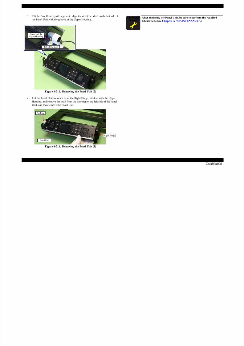
8/22/2019 TX 700 800
http://slidepdf.com/reader/full/tx-700-800 182/234
DISASSEMBLY/ASSEMBLY Disassembly/reassembly procedures specific to Artisan 700/PX700W/TX700W 182Confidential
Figure 4-210. Removing the Panel Unit (2)
4. Lift the Panel Unit so as not to let the Right Hinge interfere with the Upper
Housing, and remove the shaft from the bushing on the left side of the PanelUnit, and then remove the Panel Unit.
Figure 4-211. Removing the Panel Unit (3)
Bushing
Panel Unit
Right Hinge
EPSON Artisan 800/EPSON Stylus Photo PX800FW/TX800FW/Artisan 700/EPSON Stylus Photo PX700W/TX700W Revision A
4.3.2.2 Main Board/Grounding Plate M/B (Artisan 700/PX700W/TX700W)
Parts/Components need to be removed in advance:
Scanner Unit/Upper Left Housing/Paper Guide Top Assy/Upper Housing/Hinge/
Rear Right Housing/Right Housing
Removal procedure
1. Disconnect all the cables and FFCs connected to the section A on the Main
Board. (See "Connectors on the Main Board" (p. 111).)
2. Remove the screw (x1) that secures the Grounding Plate M/B, and remove the
Grounding Plate M/B together with the Grounding Plate Sheet M/B.
Figure 4-213. Removing the Grounding Plate M/B
The disassembly/reassembly procedures for Artisan 800/PX800FW/
TX800FW differ from those of Artisan 700/PX700W/TX700W, see
4.2.2.2 Main Board / Grounding Plate M/B (p111) for the
procedures.
Section A
C.B.S. 3x6 (7±1Kgfcm)
Grounding Plate M/B
Grounding Plate Sheet M/B
Positioning hole & dowelDouble-sided tape

8/22/2019 TX 700 800
http://slidepdf.com/reader/full/tx-700-800 183/234
DISASSEMBLY/ASSEMBLY Disassembly/reassembly procedures specific to Artisan 700/PX700W/TX700W 183Confidential
Figure 4-212. Connector positions on the Main Board
3. Remove the screw that secures the Ferrite Core Holder A, and remove the
Ferrite Core Holder A.
Figure 4-214. Removing the Ferrite Core Holder A
CN501
CN22
CN21
CN24
CN49
CN14
CN8
CN41 CN10
CN12
CN9 CN33
CN6 CN4 CN3 CN2
CN1
CN5
CN19
CN31
CN7
CN32
CN13
Section B
Section A
C.B.S.(P2) 3x8 (8±1Kgfcm)
Ferrite Core Holder A
Holder IC Shield Plate
Positioning hole & dowelDouble-sided tape
EPSON Artisan 800/EPSON Stylus Photo PX800FW/TX800FW/Artisan 700/EPSON Stylus Photo PX700W/TX700W Revision A
4. Disconnect the cables and FFCs connected to the section B of the Main
Board. (See Fig. 4-212.)
5. Remove the screw (x1) that secures the Right Cable Frame and the Main
Board. (See Fig. 4-212.)
6. Remove the screws (x3) that secure the Main Board Unit and remove the
Main Board Unit.
7. Remove the screws (x6) that secure the Upper Shield Plate M/B and remove
the Upper Shield Plate M/B.
Step 5
Right Cable Frame
Rearside
Backside
Bottom side
Upper Shield Plate M/B

8/22/2019 TX 700 800
http://slidepdf.com/reader/full/tx-700-800 184/234
DISASSEMBLY/ASSEMBLY Disassembly/reassembly procedures specific to Artisan 700/PX700W/TX700W 184Confidential
Figure 4-215. Removing the Main Board (1)
Figure 4-216. Removing the Main Board (2)
8. Remove the screws (x3) that secure the Main Board, and remove the Lower
Shield Plate M/B from the Main Board.
Figure 4-217. Removing the Main Board (3)
C.B.P. 3x10 (6±1Kgfcm)C.B.S. 3x6 (7±1Kgfcm)
C.B.P. 3x8 (6±1Kgfcm)
Positioning hole & dowel
Main Board UnitDowel & groove C.B.S. 3x6 (8±1Kgfcm)
C.B.S. 3x6 (4±1Kgfcm)
C.P. 3x6 (4±1Kgfcm)
1
2
3
C.B.S. 3x6 (8±1Kgfcm)
C.B.S. 3x10 (8±1Kgfcm)
Lower Shield Plate M/B
Main Board
Positioning hole & dowel
EPSON Artisan 800/EPSON Stylus Photo PX800FW/TX800FW/Artisan 700/EPSON Stylus Photo PX700W/TX700W Revision A
Align the positioning holes (x2) on the Main Board with the
dowels (x2) of the Lower Shield Plate M/B. (See Fig. 4-217.)
Tighten the screws in the order given in Fig. 4-217.
Align the dowels (x2) of the Lower Shield Plate M/B with the
grooves (x2) of the Upper Shield Plate M/B. (See Fig. 4-216.)
Align the positioning holes (x2) of the Main Board Unit with the
dowels (x2) of the Base Frame. (See Fig. 4-215.)
Align the dowels (x2) of the Main Board Unit with thepositioning holes (x2) of the Right Cable Frame. (See Fig.
4-215.)
Insert the rib (x1) of the Grounding Plate M/B to the hole of the
Main Board Unit, and align the positioning hole (x1) of the
Grounding Plate M/B with the dowel (x1) of the Main Board
Unit, and attach the Grounding Plate M/B. (See Fig. 4-215, Fig.
4-218.)
When replacing the Grounding Plate Sheet M/B, insert the
sheet between the FFC and the Main Frame, and secure it with
double-sided tape to the Grounding Plate M/B. (See Fig. 4-213.)
When attaching the Ferrite Core Holder A, follow the
procedure below.
1. Align the dowels (x2) of the Main Board Unit with the
positioning holes (x2) of the Holder IC Shield Plate.
2. Secure the Ferrite Core Holder A and the Holder IC ShieldPlate to the Main Board Unit with the screw. (See Fig.
4-214.)
When attaching the CR Encoder FFC, follow the procedures
below.
1. Put the CR Encoder FFC through the ferrite core.
2. Connect the CR Encoder FFC to the connector (CN6) on
the Main Board.
3. Insert the rib of the Ferrite Core Holder B to the hole of the
Main Board, and secure it with the screw (x1).

8/22/2019 TX 700 800
http://slidepdf.com/reader/full/tx-700-800 185/234
DISASSEMBLY/ASSEMBLY Disassembly/reassembly procedures specific to Artisan 700/PX700W/TX700W 185Confidential
Figure 4-218. Attaching the Grounding Plate M/B
Hole
Rib
Figure 4-219. Attaching the CR Encoder FFC
For routing the FFCs, see 4.4 Routing FFC/cables (p189).
C.B.S. 3x6 (5±0.5Kgfcm)
CN6
CR Encoder FFC
Ferrite core
Ferrite Core Holder B
Align and insert the rib ofthe Ferrite Core Holder B
EPSON Artisan 800/EPSON Stylus Photo PX800FW/TX800FW/Artisan 700/EPSON Stylus Photo PX700W/TX700W Revision A
4.3.2.3 Card Slot Assy (Artisan 700/PX700W/TX700W)
Parts/Components need to be removed in advance:
Scanner Unit/Upper Left Housing/Paper Guide Top Assy/
Upper Housing/Hinge/Rear Right Housing/Right Housing/Main Board Unit/CSIC Assy/Cartridge Box Unit/Ink Supply Tube Assy
When replacing the Main Board, the MAC address need to be set if
the EEPROM data could not be read from the old Main Board. In
this case, attach the new “Label, MAC address (Parts number:
1489232)” to the position shown in Fig. 4-220 and execute
“5.2.6 MAC Address Setting (p208)”.
Figure 4-220. Position for the MAC Address Label
Label, MAC address
The disassembly/reassembly procedures for Artisan 800/
PX800FW/TX800FW differ from those of Artisan 700/
PX700W/TX700W, see 4.2.2.5 Card Slot Assy (p117) for the
procedures.
The Card Slot Assy includes the SUB Board and the STG
Board.
When powering this product, high-voltage current may be applied
on the SUB Board. To prevent ELECTRIC SHOCK, do not touch
the SUB Board section when the power is ON.
If the shock should happen, the flowing current is very tiny, about a
few hundreds μA, therefore it will not do any harm on the human
body.

8/22/2019 TX 700 800
http://slidepdf.com/reader/full/tx-700-800 186/234
DISASSEMBLY/ASSEMBLY Disassembly/reassembly procedures specific to Artisan 700/PX700W/TX700W 186 Confidential
y g pp y y
Removal procedure
1. Remove the screws (x2) that secure the Card Slot Assy and remove the
Grounding Plate.
Figure 4-221. Removing the Card Slot Assy (1)
Dowel & Groove C.B.P. 3x8 (6±1Kgfcm)
GroundingPlate
Card Slot Assy
EPSON Artisan 800/EPSON Stylus Photo PX800FW/TX800FW/Artisan 700/EPSON Stylus Photo PX700W/TX700W Revision A
2. Disconnect the AID cable from the connector on the SUB Board, and remove
the Card Slot Assy.4.3.3 Disassembling the Scanner Unit (Artisan 700/
PX700W/TX700W)
4.3.3.1 Document Cover
Parts/Components need to be removed in advance:
Scanner Unit/ADF Unit
Removal procedure
1. Release the dowels (x2) and ribs (x2) of the Document Cover with the
Document Cover closed, and remove the Document Cover from the Scanner
Upper Housing in the direction of the arrow.
AID cable
Card Slot Assy
Connector on the SUB Board
The disassembly/reassembly procedures for Artisan 800/PX800FW/
TX800FW differ from those of Artisan 700/PX700W/TX700W, see
4.2.4 Disassembling Scanner Unit (p156) for the procedures.
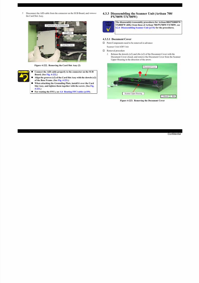
8/22/2019 TX 700 800
http://slidepdf.com/reader/full/tx-700-800 187/234
DISASSEMBLY/ASSEMBLY Disassembly/reassembly procedures specific to Artisan 700/PX700W/TX700W 187 Confidential
Figure 4-222. Removing the Card Slot Assy (2)
Figure 4-223. Removing the Document Cover
Connect the AID cable properly to the connector on the SUB
Board. (See Fig. 4-222.)
Align the grooves (x2) of the Card Slot Assy with the dowels (x2)
of the Base Frame. (See Fig. 4-221.)
When attaching the Grounding Plate, install it over the CardSlot Assy, and tighten them together with the screw. (See Fig.
4-221.)
For routing the FFCs, see 4.4 Routing FFC/cables (p189).
Dowel Rib
Scanner Upper Housing
Document Cover
EPSON Artisan 800/EPSON Stylus Photo PX800FW/TX800FW/Artisan 700/EPSON Stylus Photo PX700W/TX700W Revision A
4.3.3.2 Scanner Upper Housing (Artisan 700/PX700W/TX700W)
Parts/Components need to be removed in advance:
Scanner Unit/ADF Unit/Document Cover
Removal procedure
1. Remove the screws (x7) that secure the Scanner Upper Housing.
2. Release the hooks (x3) that secure the Scanner Upper Housing.
3. Release the ribs (x4) on the Scanner Upper Housing, and remove the Scanner
Upper Housing in the direction of the arrow.
It is recommended to remove the Scanner Upper Housing in a
clean room or on a clean bench to keep away from dust and dirt.
Be careful not to damage the document glass on the ScannerUpper Housing.
Bottom side
Scanner Upper Housing
Rib

8/22/2019 TX 700 800
http://slidepdf.com/reader/full/tx-700-800 188/234
DISASSEMBLY/ASSEMBLY Disassembly/reassembly procedures specific to Artisan 700/PX700W/TX700W 188Confidential
Figure 4-224. Removing the Scanner Upper Housing (1)
Figure 4-225. Removing the Scanner Upper Housing (2)
C.B.P. 3x10 (5±1kgfcm)
C.B.P. 3x8 (5±1kgfcm)Hook
Scanner Upper Housing
When installing the Scanner Upper Housing, see “4.2.4.1 Scanner
Upper Housing (Artisan 800/PX800FW/TX800FW) (p156)”.
EPSON Artisan 800/EPSON Stylus Photo PX800FW/TX800FW/Artisan 700/EPSON Stylus Photo PX700W/TX700W Revision A
4.4 Routing FFC/cables
ADF/SCANNER (ARTISAN 800/PX800FW/TX800FW)
Note * : See Fig. 4-228 for the connector positions on the Main Board (Artisan 800/PX800FW/TX800FW).
ADF/SCANNER (ARTISAN 700/PX700W/TX700W)
Note * : See Fig. 4-230 for the connector positions on the Main Board (Artisan 700/
PX700W/TX700W).
No. FFC/cable name CN No.* Remarks
1 ADF Motor Cable CN25Artisan 800/PX800FW/TX800FW
only
2 ADF Sensor Cable CN51Artisan 800/PX800FW/TX800FW
only
3 Scanner Cover Open Sensor FFC CN10 Ferrite Core x1
4 Scanner Carriage FFC CN41 Ferrite Core x1
5 Scanner CR Encoder FFC CN49 ---
6 Grounding Wire (x2) --- ---
No. FFC/cable name CN No.* Remarks
1 Scanner Cover Open Sensor FFC CN10 Ferrite Core x1
2 Scanner Carriage FFC CN41 Ferrite Core x1
3 Scanner CR Encoder FFC CN49 ---
4 Grounding Wire (x1) --- ---
Grounding Wire

8/22/2019 TX 700 800
http://slidepdf.com/reader/full/tx-700-800 189/234
DISASSEMBLY/ASSEMBLY Routing FFC/cables 189Confidential
Figure 4-226. ADF/Scanner (Artisan 800/PX800FW/TX800FW)
Figure 4-227. ADF/Scanner (Artisan 700/PX700W/TX700W)
Grounding Wire fromthe Scanner Unit
Grounding Wire fromthe ADF Unit
Ferrite Core B:
Put the Scanner Cover Open Sensor FFCthrough this and secure it together withthe FFC on the Main Board Unit with thedouble-sided tape.
Scanner CR Encoder FFC
ADF Motor Cable
Scanner Carriage FFC
Scanner Cover OpenSensor FFC
ADF Sensor Cable
Double-sided tape
Ferrite Core A: Put the Scanner Carriage FFCthrough this and attach it tothe Upper Housing.
Scanner CR Encoder FFC
Scanner Carriage FFC
Scanner Cover OpenSensor FFC
Double-sided tape
Ferrite Core B: Put the Scanner Cover Open SensorFFC through this and secure it togetherwith the FFC on the Main Board Unitwith the double-sided tape.
Ferrite Core A: Put the Scanner Carriage FFC
through this and attach it tothe Upper Housing.

8/22/2019 TX 700 800
http://slidepdf.com/reader/full/tx-700-800 190/234
EPSON Artisan 800/EPSON Stylus Photo PX800FW/TX800FW/Artisan 700/EPSON Stylus Photo PX700W/TX700W Revision A
MAIN BOARD (TOP SIDE) (ARTISAN 700/PX700W/TX700W)
Following describes routing the cables and FFCs that connect to the Main Board.
Start Cable Route CN No.
1
PE Sensor Cable
(Ferrite Core x2)a → groove A → F → G → b CN9
PF Encoder FFC Double-sided tape (x4) CN8
2PF Motor Cable
(Ferrite Core x1)E → c → C → B CN22
3CR Motor Cable
(Ferrite Core x1)H → d → C → B CN21
4 Decompression Pump Motor Cable H → C → B CN24
5
Duplex Unit Sensor Cable
D → A
CN13
CDR Tray Sensor Cable CN14
Photo Tray Sensor Cable D → A → F → G CN12
2
4
6
d
c
A
BC
E
D
H
A H
a d
1 6
Groove BPower Supply Unit Cable
PF Motor Cable
CR Motor Cable
Decompression PumpMotor Cable
Hook
Double-sided tape
Ferrite Core position
Routing hole for FFC/cable

8/22/2019 TX 700 800
http://slidepdf.com/reader/full/tx-700-800 191/234
DISASSEMBLY/ASSEMBLY Routing FFC/cables 191Confidential
Figure 4-230. Connector positions on the Main Board
(Artisan 700/PX700W/TX700W)
Figure 4-231. Main Board (Artisan 700/PX700W/TX700W)
6 Power Supply Unit Cable
Groove B (Insert it between Base
Frame and Decompression Pump
Unit)
CN501
CN501
CN22
CN21
CN24
CN49
CN14
CN8
CN41 CN10
CN12
CN9
CN6 CN4 CN3 CN2
CN1
CN5
CN19
CN31
CN7
CN32
CN13
G
1
3
45
b
a
Groove A
F
Duplex UnitSensor Cable
CDR TraySensor Cable
PF Encoder FFC
PE Sensor Cable
Photo Tray
Sensor Cable
EPSON Artisan 800/EPSON Stylus Photo PX800FW/TX800FW/Artisan 700/EPSON Stylus Photo PX700W/TX700W Revision A
CARD SLOT ASSY
Note * : See Fig. 4-228 for the connector positions on the Main Board.
No. FFC/cable name CN No.* Remarks
1 I/F FFC (Infra-red) CN32Mounted only in Japanese
models.
2 SUB FFC CN7 ---
3 STG FFC CN31 Ferrite Core x2
Bottom of theCard Slot Assy
Acetate tapeFerrite Core
Ferrite Core Holder A
SUB FFC: Route this between Ferrite Core and Base Frame, and
secure it to the Main Board Unit with double-sided tape
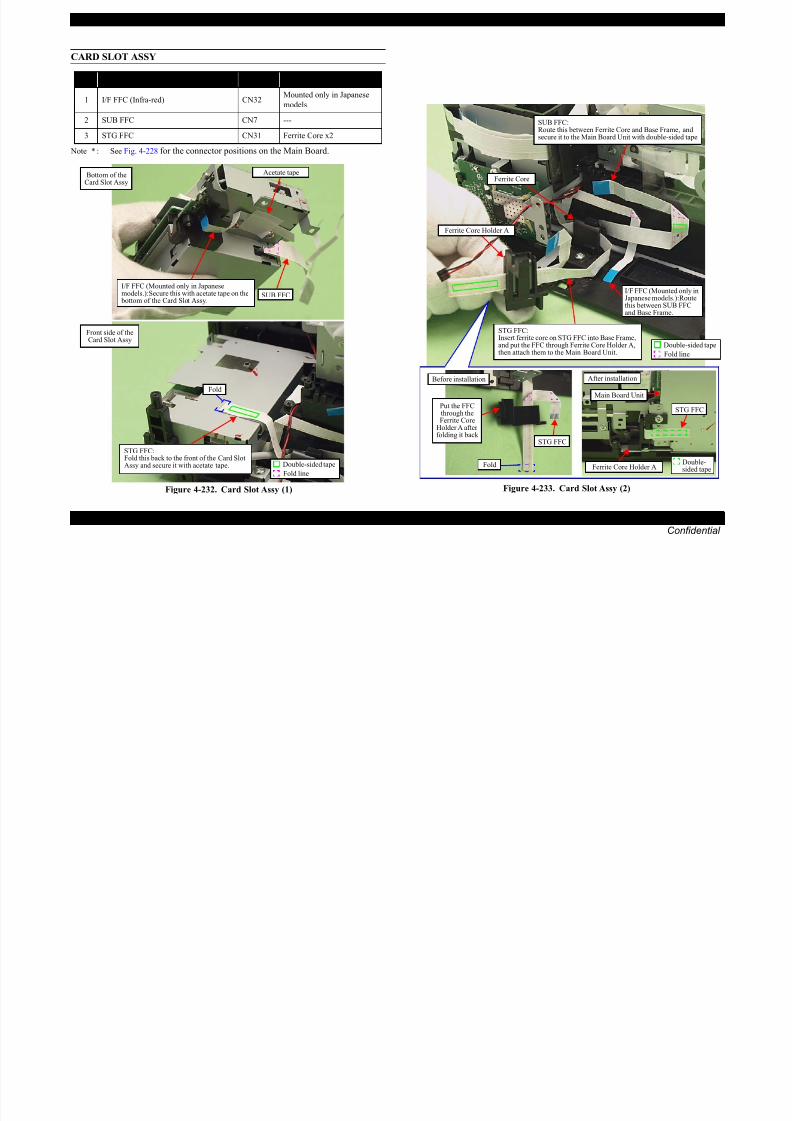
8/22/2019 TX 700 800
http://slidepdf.com/reader/full/tx-700-800 192/234
DISASSEMBLY/ASSEMBLY Routing FFC/cables 192Confidential
Figure 4-232. Card Slot Assy (1) Figure 4-233. Card Slot Assy (2)
STG FFC: Fold this back to the front of the Card SlotAssy and secure it with acetate tape.
Front side of theCard Slot Assy
Double-sided tape
Fold line
Fold
SUB FFC
I/F FFC (Mounted only in Japanesemodels.):Secure this with acetate tape on the bottom of the Card Slot Assy.
STG FFC
Double-sided tape
Main Board Unit
Ferrite Core Holder A
After installation
Fold
STG FFC
Put the FFCthrough theFerrite Core
Holder A afterfolding it back
Before installation
Double-sided tape
Fold line
I/F FFC (Mounted only inJapanese models.):Routethis between SUB FFCand Base Frame.
STG FFC: Insert ferrite core on STG FFC into Base Frame,and put the FFC through Ferrite Core Holder A,then attach them to the Main Board Unit.
EPSON Artisan 800/EPSON Stylus Photo PX800FW/TX800FW/Artisan 700/EPSON Stylus Photo PX700W/TX700W Revision A
MAIN BOARD (REAR SIDE OF THE CARTRIDGE BOX) (ARTISAN 800/PX800FW/TX800FW)
Note * : See Fig. 4-228 for the connector positions on the Main Board.
MAIN BOARD (BEHIND CARTRIDGE BOX) (ARTISAN 700/PX700W/TX700W)
Note * : See Fig. 4-230 for the connector positions on the Main Board.
No. FFC/cable name CN No.* Remarks
1 CR Encoder FFC CN6 Ferrite Core x2
2 Head FFC (x4) CN1,2,3,4 Ferrite Core x1
3 CSIC FFC CN5 ---
Ferrite core: Put Head FFC (x4) and CR Encoder FFC throughthis, and place it on the rear side of Cartridge Boxand secure it with double-sided tape.
No. FFC/cable name CN No.* Remarks
1 Panel FFC CN33 Ferrite core (x1)
2 CR Encoder FFC CN6 ---
3 Head FFC (x4) CN1,2,3,4 ---4 CSIC FFC CN5 ---
Panel FFC
CR Encoder FFCPut Panel FFC onlythrough ferrite core.

8/22/2019 TX 700 800
http://slidepdf.com/reader/full/tx-700-800 193/234
DISASSEMBLY/ASSEMBLY Routing FFC/cables 193Confidential
Figure 4-234. Rear side of the Cartridge Box(Artisan 800/PX800FW/TX800FW) Figure 4-235. Routing to the FFC Holder(Artisan 700/PX700W/TX700W)
CSIC FFC
Head FFC (x4): Route them through the ribs (x4)and ferrite core, and secure themon the rear side of Cartridge Boxwith double-sided tape.
CR Encoder FFC: Route this through the ribs(x4) and ferrite core. Fold line
RibDouble-sided tape
Head FFC (x4)CSIC FFC
Fold line
RibDouble-sided tape
Spacer: Attach it to Panel FFC with double-sidedtape, and secure it with the hooks (x3).
CR Encoder FFC & Head FFC (x4): Route them through the ribs (x4),
and secure them with double-sidedtape (x2) behind the Cartridge Box.
Panel FFC: Route it through the ribs(x4), and ferrite core.
EPSON Artisan 800/EPSON Stylus Photo PX800FW/TX800FW/Artisan 700/EPSON Stylus Photo PX700W/TX700W Revision A
ROUTING THROUGH THE FFC HOLDER
See Fig. 4-228 for the connector positions on the Main Board.
ROUTING AROUND THE PRINTER MECHANISM
Note * : See Fig. 4-228 for the connector positions on the Main Board.
No. FFC/cable name CN No.* Remarks
1 CR Encoder FFC CN6 ---
2 Head FFC (x4) CN1,2,3,4 ---
FFC Holder
No. FFC/cable name CN No.* Remarks
1 Plunger cable CN19 ---
Do not tuck
Acetate tape
Route this not to let it get
caught between Cartridge SlotAssy and Cartridge Box.
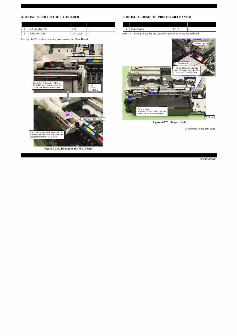
8/22/2019 TX 700 800
http://slidepdf.com/reader/full/tx-700-800 194/234
DISASSEMBLY/ASSEMBLY Routing FFC/cables 194Confidential
Figure 4-236. Routing to the FFC Holder
Figure 4-237. Plunger Cable
(Continued to the next page.)
RibHoleFold line
Insert the CR Encoder FFC andHead FFC (x4) together to the ribon the FFC Holder and the hole.
Ink Supply Tube Assy
Cover Ink Supply Tube Assy with CREncoder FFC and Head FFC (x4), andsecure them to the FFC Holder.
Hook
Plunger cable: Route this to the hooks (x10) andsecure it with acetate tape (x1).
EPSON Artisan 800/EPSON Stylus Photo PX800FW/TX800FW/Artisan 700/EPSON Stylus Photo PX700W/TX700W Revision A
Note * : See Fig. 4-228 for the connector positions on the Main Board.
Note " * " : See Fig. 4-228 for the connector positions on the Main Board.
No. FFC/cable name CN No.* Remarks
1 PF Motor Cable CN22 Ferrite Core x1
2 Power Supply Unit cable CN501 ---
Views without the CDR
Power Supply Unit cable: Route this through the groove on Base Frame
PF Motor cable: Place the relay connector to the hole onBase Frame, and route the cable throughthe hooks (x3) and the groove (x1).
Relay Connector
Do not let thisget caught
Rightside
No. FFC/cable name CN No.* Remarks
1 PE Sensor Cable CN9 Ferrite Core x1
Transmission Holder Assy
To the dowel of Base Frame
PE Sensor cable: Route this through the grooves (x3)of Transmission Holder Assy.
To PE Sensor

8/22/2019 TX 700 800
http://slidepdf.com/reader/full/tx-700-800 195/234
DISASSEMBLY/ASSEMBLY Routing FFC/cables 195Confidential
Figure 4-238. PF Motor Cable, Power Supply Unit Cable
Figure 4-239. PE Sensor Cable
Power Unit cable: Route this through the hooks (x5)and secure it with acetate tape.
Hook securing PF Motor cable
Hook securing Power Supply Unit cable
Groove
PF Motor cable: Route through the hooks (x5)and secure with the acetate tape.
Acetate tape
Views without the CDRRoute this through the groove on Base Frame. get caught.
To Transmission Holder Assy
Groove
Dowel
To Main Board
Ferrite core
PE Sensor cable: Route this through the dowels, andattach ferrite core into Base Frame.
C H A P T E R
5ADJUSTMENT

8/22/2019 TX 700 800
http://slidepdf.com/reader/full/tx-700-800 196/234
Confidential
5ADJUSTMENT

8/22/2019 TX 700 800
http://slidepdf.com/reader/full/tx-700-800 197/234

8/22/2019 TX 700 800
http://slidepdf.com/reader/full/tx-700-800 198/234

8/22/2019 TX 700 800
http://slidepdf.com/reader/full/tx-700-800 199/234
EPSON Artisan 800/EPSON Stylus Photo PX800FW/TX800FW/Artisan 700/EPSON Stylus Photo PX700W/TX700W Revision A
Table 5-3. Additional Functions
Adjustment Item Purpose Method Outline Tool
A d d i t i o n
a l F u n c t i o n s
Final check pattern
A4 size Use this to check if the all adjustments
have been properly made.
Select the target menu from the Adjustment Program and execute
it.
• Adjustment
ProgramUS Letter size
EEPROM dumpUse this to readout the EEPROM data for
analysis.
Read out all the data stored on the EEPROM and store it as a file. • Adjustment
Program
Printer information
check
Manual CL counter Use this to readout information on the
printer operations.
Select the desired menu in the Adjustment Program and execute it. • Adjustment
ProgramFirst TI recieved time
The latest Fatal error code
ROM Version

8/22/2019 TX 700 800
http://slidepdf.com/reader/full/tx-700-800 200/234
ADJUSTMENT Adjustment Items and Overview 200Confidential
EPSON Artisan 800/EPSON Stylus Photo PX800FW/TX800FW/Artisan 700/EPSON Stylus Photo PX700W/TX700W Revision A
5.1.2 Required Adjustments
The table below lists the required adjustments depending upon the parts being repaired
or replaced. Find the part(s) you removed or replaced, and check which adjustment(s)
must be carried out.
Note : <Meaning of the marks in the table>
“O” indicates that the adjustment must be carried out. “O*” indicates that the
adjustment is recommended. “---” indicates that the adjustment is not required.
If you have removed or replaced multiple parts, make sure to check the requiredadjustments for the all parts. And when multiple adjustments must be carried out, be
sure to carry out them in the order given in the “Priority” row.
When the EEPROM data copy is impossible with the main
board that needs to be replaced, the Waste Ink Tray Assy and
the Lower Paper Guide Waste Ink Pad Assy must be replaced
after replacing the main board with a new one.
After all required adjustments are completed, use the “Final
check pattern print” function to print all adjustment patterns
for final check. If you find a problem with the printout patterns,
carry out the adjustment again.
When using a new main board for replacing the Printer
Mechanism, the Initial setting must have been made to the main
board.
Table 5-4. Required Adjustment List
Priority 1 2 3 4 5 6 7 8 9 10 11 12 13 14 15 16 17 18 19 20 21 22 23
s t m e n t
n s i o n a d j u s t m
e n t
s i o n a d j u s t m
e n t
d a t a c o p y
e t t i n g
I n p u t
n t e n a n c e c o u
n t e r
s r e a d / w r i t e
h a r g e
I n p u t
A d j u s t m e n t
o n a d j u s t m e n
t
s t m e n t
a d j u s t m e n t
p e c t i o n
u s t m e n t
a t i o n o f f s e t
o t e c t i o n c o n
t r o l
o t e c t i o n c o n t r o l
s t m e n t
u s t m e n t
u s t m e n t
A d j u s t m e n t
Adjustment Item

8/22/2019 TX 700 800
http://slidepdf.com/reader/full/tx-700-800 201/234
ADJUSTMENT Adjustment Items and Overview 201Confidential
P G A d j u s
C R t i m i n g b e l t t e n
P F t i m i n g b e l t t e n s
E E P R O M d
I n i t i a l s e
U S B I D
C o n s u m a b l e s m a i n
M A C a d d r e s s
I n k C h
H e a d I D
T O P M a r g i n A
F i r s t d o t p o s i t i o
P W a
d j u s
H e a d a n g u l a r
A I D i n s p
B i - D a d j u
P F d e t e r i o r a
C R m o t o r h e a t p r o
P F m o t o r h e a t p r o
P F a d j u s
B R S A d j u
P F P A d j u
T o u c h P a n e l A
Main board
Remove --- --- --- --- --- --- --- --- --- --- --- --- --- --- --- --- --- --- --- --- --- --- O
Replace
(Read
OK)
--- --- --- O --- --- --- --- --- --- --- --- --- --- --- --- --- --- --- --- --- --- O
Replace
(Read
NG)
--- --- --- --- O O (Replace
the pad)O --- O O O O O --- O
O
Input
max.
value
(10000)
O O O O O O
Panel Unit(EPSON Artisan 800/
EPSON Stylus Photo
PX800FW/TX800FW
Only)
Remove --- --- --- --- --- --- --- --- --- --- --- --- --- --- --- --- --- --- --- --- --- --- O
Replace --- --- --- --- --- --- --- --- --- --- --- --- --- --- --- --- --- --- --- --- --- --- O
Part Name
EPSON Artisan 800/EPSON Stylus Photo PX800FW/TX800FW/Artisan 700/EPSON Stylus Photo PX700W/TX700W Revision A
PrintheadRemove O --- --- --- --- --- --- --- --- --- O O O O --- O --- --- --- O O O O
Replace O --- --- --- --- --- --- --- O O O O O O O O --- --- --- O O O O
Ink Supply IC
Horder Assy
Remove --- --- --- --- --- --- --- --- --- --- --- --- --- --- --- --- --- --- --- --- --- --- O
Replace --- --- --- --- --- --- --- --- O --- --- --- --- --- --- --- --- --- --- --- --- --- O
Card Slot AssyRemove --- --- --- --- --- --- --- --- --- --- --- --- --- --- --- --- --- --- --- --- --- --- O
Replace --- --- --- --- --- --- --- --- --- --- --- --- --- --- O --- --- --- --- --- --- --- O
Power Supply Remove --- --- --- --- --- --- --- --- --- --- --- --- --- --- --- --- --- --- --- --- --- --- O
Table 5-4. Required Adjustment List
Priority 1 2 3 4 5 6 7 8 9 10 11 12 13 14 15 16 17 18 19 20 21 22 23
P G A d j u s t m e n t
C R t i m i n g b e l t t e n s i o n a d j u s t m e n t
P F t i m i n g b e l t t e n s i o n a d j u s t m e n t
E E P R O M d a t a c o p y
I n i t i a l s e t t i n g
U S B I D I n p u t
C o n s u m a b l e s
m a i n t e n a n c e c o u n t e r
M A C a d
d r e s s r e a d / w r i t e
I n
k C h a r g e
H e a
d I D I n p u t
T O P M a r g i n A d j u s t m e n t
F i r s t d o t p o s i t i o n a d j u s t m e n t
P W a
d j u s t m e n t
H e a d a n g
u l a r a d j u s t m e n t
A I D
i n s p e c t i o n
B i - D
a d j u s t m e n t
P F d e t e
r i o r a t i o n o f f s e t
C R m o t o r h e
a t p r o t e c t i o n c o n t r o l
P F m o t o r h e a t p r o t e c t i o n c o n t r o l
P F a d j u s t m e n t
B R S
A d j u s t m e n t
P F P
A d j u s t m e n t
T o u c h P a n e l A d j u s t m e n tAdjustment Item
Part Name

8/22/2019 TX 700 800
http://slidepdf.com/reader/full/tx-700-800 202/234
ADJUSTMENT Adjustment Items and Overview 202Confidential
Unit Replace --- --- --- --- --- --- --- --- --- --- --- --- --- --- --- --- --- O O --- --- --- O
CR Motor Remove --- O --- --- --- --- --- --- --- --- --- O O --- --- O --- --- --- --- --- --- O
Replace --- O --- --- --- --- --- --- --- --- --- O O --- --- O --- O --- --- --- --- O
PF Motor Remove --- --- O --- --- --- --- --- --- --- --- --- --- --- --- --- --- --- --- --- O O O
Replace --- --- O --- --- --- --- --- --- --- O O --- --- --- --- --- --- O --- O O O
CR UnitRemove O O --- --- --- --- --- --- --- --- O O O O --- O --- --- --- --- O O O
Replace O O --- --- --- --- --- --- --- --- O O O O --- O --- O --- --- O O O
EJ Frame AssyRemove --- --- --- --- --- --- --- --- --- --- --- --- --- --- --- O* O --- O O O O O
Replace --- --- --- --- --- --- --- --- --- --- --- --- --- --- --- O* O --- O O O O O
Main FrameRemove --- --- --- --- --- --- --- --- --- --- O O O O O O O O O O O O O
Replace --- --- --- --- --- --- --- --- --- --- O O O O O O O O O O O O O
Ink System
Remove --- --- --- --- --- --- --- --- --- --- --- --- --- --- --- --- --- --- --- --- --- --- O
Replace --- --- --- --- --- --- --- --- --- --- --- --- --- --- O --- --- --- --- --- --- --- O
Upper Paper
Guide
Remove --- --- --- --- --- --- --- --- --- --- O --- --- --- --- --- --- --- --- O O O O
Replace --- --- --- --- --- --- --- --- --- --- O --- --- --- --- ---
O
Reset
to 0
--- --- O O O O
EPSON Artisan 800/EPSON Stylus Photo PX800FW/TX800FW/Artisan 700/EPSON Stylus Photo PX700W/TX700W Revision A
Paper Guide
Front Assy
Remove --- --- O --- --- --- --- --- --- --- O* O* O O --- O --- --- --- O O O O
Replace --- --- O --- --- --- --- --- --- --- O* O* O O --- O --- --- --- O O O O
Waste Ink Tray
Assy
Remove --- --- --- --- --- --- --- --- --- --- --- --- --- --- --- --- --- --- --- --- --- --- O
Replace --- --- --- --- --- --- O --- --- --- --- --- --- --- --- --- --- --- --- --- --- --- O
Lower Paper
Guide Waste
Ink Pad Assy
Remove --- --- --- --- --- --- --- --- --- --- --- --- --- --- --- --- --- --- --- --- --- --- O
Replace --- --- --- --- --- --- O --- --- --- --- --- --- --- --- --- --- --- --- --- --- --- O
Printer
Table 5-4. Required Adjustment List
Priority 1 2 3 4 5 6 7 8 9 10 11 12 13 14 15 16 17 18 19 20 21 22 23
P G A d j u s t m e n t
C R t i m i n g b e
l t t e n s i o n a d j u s t m e n t
P F t i m i n g b e l t t e n s i o n a d j u s t m e n t
E E P R O M d a t a c o p y
I n i t i a l s e t t i n g
U S B I D I n p u t
C o n s u m a b l e s
m a i n t e n a n c e c o u n t e r
M A C a d
d r e s s r e a d / w r i t e
I n
k C h a r g e
H e a
d I D I n p u t
T O P M a r g i n A d j u s t m e n t
F i r s t d o t p o s i t i o n a d j u s t m e n t
P W a
d j u s t m e n t
H e a d a n g u l a r a d j u s t m e n t
A I D
i n s p e c t i o n
B i - D
a d j u s t m e n t
P F d e t e
r i o r a t i o n o f f s e t
C R m o t o r h e
a t p r o t e c t i o n c o n t r o l
P F m o t o r h e a t p r o t e c t i o n c o n t r o l
P F a d j u s t m e n t
B R S
A d j u s t m e n t
P F P
A d j u s t m e n t
T o u c h P a n e l A d j u s t m e n tAdjustment Item
Part Name

8/22/2019 TX 700 800
http://slidepdf.com/reader/full/tx-700-800 203/234
ADJUSTMENT Adjustment Items and Overview 203Confidential
Printer
MechanismReplace --- --- --- --- --- --- --- --- --- --- O O O O O O O O O O O O O
EPSON Artisan 800/EPSON Stylus Photo PX800FW/TX800FW/Artisan 700/EPSON Stylus Photo PX700W/TX700W Revision A
5.2 Adjustment by Using Adjustment Program(TBD)
This section explains how to judge print samples by using the adjustment program.
Follow the instructions of the adjustment program for details of the adjustment
methods.
5.2.1 Top Margin AdjustmentPatterns are printed as shown below.
5.2.2 Bi-D Adjustment
The pattern shown below is printed for each of the PG settings and four print modes.
Figure 5-2. Bi-D Adjustment Pattern
How to Judge
Find the pattern with no gaps or overleaps of the left and right pattern, and enter the
value of that pattern.
Additional information
If an appropriate pattern is not printed, enter the nearest value and then print the
patterns again.
-9
-8
-7
-6
-5
-4
-3
-2
-1
0
1
2
3
4
5
6
7
8
9
5mm
Top margin printout
Bottom margin
2 3 4 5 6 7-1 0 1

8/22/2019 TX 700 800
http://slidepdf.com/reader/full/tx-700-800 204/234
ADJUSTMENT Adjustment by Using Adjustment Program (TBD) 204Confidential
Figure 5-1. Top Margin Adjustment Pattern
How to Judge
Measure the distance from the paper edge to the printed line. Enter the value for the
line that is exactly 5 mm away from the edge.
-9
-8
-7
-6
-5
-4
-3
-2
-1
0
1
2
3
4
5
6
7
8
9
5mm
Example for judgement
OK NGNG
GapOverlap
EPSON Artisan 800/EPSON Stylus Photo PX800FW/TX800FW/Artisan 700/EPSON Stylus Photo PX700W/TX700W Revision A
5.2.3 PW Adjustment/First Dot Position Adjustment
Patterns are printed as shown below.
PW Adjustment
How to Judge
Enter the value of the line located 5mm away from each edge.
Example: In the left figure, enter “0” (top), “5” (bottom), “-3” (left) and “0” (right).
First Dot Position Adjustment
How to Judge
Enter the value of the point of intersection of the PW Adjustment pattern line and First
Dot Position Adjustment pattern line on the left.
Measure the distance from the left edge of the paper to the printed line. Enter the value
for the line that is exactly 5 mm away from the edge.
Example: In the left figure, enter “2” since the lines intersect at 2.
-8
-7
-6-5
-4
-3
-2
-1
0
1
2
3
4
5
6
7
8
9
-5 -4 -3 -2 -1 0 1 2 3 4 5 6 7 8 9 10 11 12 13 14 15
-8
-7
-6-5
-4
-3
-2
-1
0
1
2
3
4
5
6
7
8
9
5mm
Intersection point of A and B

8/22/2019 TX 700 800
http://slidepdf.com/reader/full/tx-700-800 205/234
ADJUSTMENT Adjustment by Using Adjustment Program (TBD) 205Confidential
Figure 5-3. PW Adjustment Pattern/First Dot Position Adjustment Pattern
9
10
11
12
13
14
15
16
17
18
19
-5-4-3-2-10123456789101112131415
9
10
11
12
13
14
1516
17
18
19
A: PW Adjustment pattern line
B: First Dot Position Adjustment pattern line
EPSON Artisan 800/EPSON Stylus Photo PX800FW/TX800FW/Artisan 700/EPSON Stylus Photo PX700W/TX700W Revision A
5.2.4 Head Angular Adjustment
Two patterns are printed as shown below.
Band pattern
The following pattern is printed. The lines below “1 to 80” are printed while the
carriage moves from the home to the other side, and lines below “80 to 1” are printed
while the carriage returns to the home.
Figure 5-4. Head Angular Adjustment Printout Pattern (1)
Microweave Pattern
Figure 5-5. Head angular adjustment Pattern Printing (2)
How to Judge
Examine the printout patterns (+2 to -2) and select the value for the group of which the
gaps between the 2 color bars are the smallest.
Additional information
If no appropriate pattern is found, reassemble/replace the Printhead.
When “+2” or “-2” is the group of which the gaps between the 2 color bars are thesmallest, reassemble/replace the Printhead.
-3
-2
-1
0
Example for judgement
NG +2 +1 0 -1 -2 NG

8/22/2019 TX 700 800
http://slidepdf.com/reader/full/tx-700-800 206/234
ADJUSTMENT Adjustment by Using Adjustment Program (TBD) 206 Confidential
g g j ( )
How to Judge
Examine the printout patterns and enter the value (-3 to 3) for the most straight lines.
Additional informationWhen “3” or “-3” is the most straight lines, it indicates that the Printhead is not
installed correctly. Reassemble the Printhead and carry out this adjustment again.
Example for judgement
NG OK
NGOK
Gap
EPSON Artisan 800/EPSON Stylus Photo PX800FW/TX800FW/Artisan 700/EPSON Stylus Photo PX700W/TX700W Revision A
5.2.5 PF Adjustment
PF-Standard Area
Patterns are printed as shown below.
PF-Bottom Edge Area
Patterns are printed as shown below.
Figure 5-7. PF Adjustment (Bottom Edge Area) Pattern
How to Judge
Input the value shown above the patterns which has no gap between the upper pattern
and the lower pattern, and also the both upper and lower patterns do not overlap each
other.
Example: In the above figure, patterns below “4” has no gap and overlap, so input “4”.
Additional information
In case that all patterns have gap or overlap, select the value for the pattern which has
4
2
0
-2
-4
5
3
1
-1
-3
2 3 4 5 6 7 81Upper block
Lower block

8/22/2019 TX 700 800
http://slidepdf.com/reader/full/tx-700-800 207/234
ADJUSTMENT Adjustment by Using Adjustment Program (TBD) 207 Confidential
Figure 5-6. PF Adjustment (Standard Area) Pattern
How to Judge
Enter the value for the group that has no gap or overlap between the upper and the
lower patterns.
p g p p p
the least gap or overlap, and print the pattern again.
Example for judgement
-5
OK NGNG
Example for judgement
OK NGNG
GapOverlap
EPSON Artisan 800/EPSON Stylus Photo PX800FW/TX800FW/Artisan 700/EPSON Stylus Photo PX700W/TX700W Revision A
5.2.6 MAC Address Setting
Overview
EPSON Artisan 800/EPSON Stylus Photo PX800FW/TX800FW have a network
function and stores there MAC address (Media Access Control Address) in the
EEPROM on the Network Board. The Network Board supplied as an ASP does not
come with the MAC address written on it, therefore, you are required to set the MAC
address to the new Network Board after replacement. The following explains the
procedure.
Setting flowchart
To avoid a conflict of MAC address on a network, make sure to
correctly follow the MAC address setting flowchart given on
the right.
The MAC Address is written correctly, The IP Address will be
initialized also.
The user should be notified of the change of MAC address
because of the following reasons. • If the user has set the printer’s MAC address on a router, the
repaired printer with a new MAC address cannot be
connected to the network.
You are required to enter the last six digits of the MAC address
(xx:yy:zz) on the Adjustment Program.
MAC address example: 00:00:48:xx:yy:zz
(“xx, yy, zz” represents a value unique to each printer)
Yes
No
Replace the Network Board with a new one.
Replace the Network Board with anew one.
END
Is the MAC address onthe label readable?
No
Attach a new MAC address label on the Upper M/B Shield Plate.
START
Enter the MAC address written onthe label using the Adjustment
Program.

8/22/2019 TX 700 800
http://slidepdf.com/reader/full/tx-700-800 208/234
ADJUSTMENT Adjustment by Using Adjustment Program (TBD) 208Confidential
Preparation
When replacing the Network Board, make sure to note down the MAC address written
on a label on the Upper M/B Shield Plate. If the address is not readable due to
contamination or any other cause, attach a new MAC address label (part code:
1489231) and note down the new address. See “ 4.2.2.2 Main Board / Grounding Plate
M/B (p111) ” for description about the label position.
Figure 5-8. MAC Address Setting Flowchart
• The default printer name on a network consists of “EPSON”
and the last six digits of the MAC address. Therefore, the
printer name becomes different from the previous one. Enter the new MAC address using the
Adjustment Program.
END
EPSON Artisan 800/EPSON Stylus Photo PX800FW/TX800FW/Artisan 700/EPSON Stylus Photo PX700W/TX700W Revision A
Setting procedure
1. Connect the printer and a computer using a LAN cable.
2. Start the Adjustment Program.
3. Select the “Initial Setting” from the menu. The initial setting screen appears.4. Enter the last six digits of MAC address into the MAC address entry field, and
click the MAC Address input button.
(Enter the address again into the second entry field to confirm it.)
Figure 5-10. MAC Address Setting Screen
The MAC address required on the Adjustment Program is written
on the MAC address label on the Upper M/B Shield Plate.
Make sure to correctly enter the address.
Figure 5-9. MAC Address Label
Label, MAC address

8/22/2019 TX 700 800
http://slidepdf.com/reader/full/tx-700-800 209/234
ADJUSTMENT Adjustment by Using Adjustment Program (TBD) 209
Confidential
5. Select the network status sheet print menu on the printer’s control panel, and print
the sheet. Check the MAC address printed on the sheet to see if it is correct. refer
to Figure 1-11 "Sample of Network Status Sheet".
EPSON Artisan 800/EPSON Stylus Photo PX800FW/TX800FW/Artisan 700/EPSON Stylus Photo PX700W/TX700W Revision A
5.2.7 AID inspection
Overview
The printer has an AID mechanism which automatically carries out nozzle check and
runs cleaning according to the number of detected clogged nozzles (AID detection
cleaning). This AID inspection check is performed using the all nozzles and inspects
the AID function if it works properly or not.
Preparation
Before starting the AID inspection check, make sure to carry out the following
adjustments and check.
Head angular adjustment
PG adjustment
Visual check of nozzle check pattern to see if dots are missing
When you find missing dots any broken lines or missing segmentson the nozzle check pattern by the visual check,
run a manual cleaning repeatedly until the check pattern is printed
without any such symptom.
8/22/2019 TX 700 800
http://slidepdf.com/reader/full/tx-700-800 210/234
ADJUSTMENT Adjustment by Using Adjustment Program (TBD) 210
Confidential
Procedure
1. Start the Adjustment Program and select the “AID inspection” from the menu.
2. Click the Perform button to run the AID inspection.
3. Check the inspection result displayed on the Adjustment Program screen.
4. When the result shows NG, check the following cables to see if they are wrongly
connected or broken.
AID cable
FFC that runs between the Main Board and the AID Board
5. Run the “AID inspection” again. If the result still shows NG, replace the AID
Board.
EPSON Artisan 800/EPSON Stylus Photo PX800FW/TX800FW/Artisan 700/EPSON Stylus Photo PX700W/TX700W Revision A
5.2.8 Banding Reduction System (BRS) Adjustment /Paper Feed Amount Profile (PFP) Correction
Overview
This section explains how to carry out BRS/PFP adjustments.
Tools and paper required to perform the adjustment
Specified Scanner to perform the adjustment
The following are the scanners that can be used for scanning the pattern in BRS/PFP
adjustment. When starting up the adjustment program, select the scanner to use.
To calculate the correction value by scanning the printed pattern
for BRS/PFP adjustment, be sure to prepare a specified scanner
beforehand. Before scanning, confirm that the document table isfree from any dirt or stain.
Table 5-5. Tools and Paper for BRS/PFP Adjustment
Tools/Paper Product Code
Common PFP Base scale 1453980
BRS Matte Paper-Heavyweight (A4) ---
PFP Premium Glossy Photo Paper (4 x 6) ---
Install the driver of the scanner to the PC in advance.
As the profile required for the adjustment is not prepared for
scanners other than the ones specified below, BRS/PFP
Adjustment can not be carried out by the other scanners.
Table 5-6. Specified Scanner for BRS/PFP Adjustment
Model Name Sensor type Remarks
Perfection 4990 Photo CCD
Perfection V700 Photo/V750 Pro CCD
EPSON Stylus Photo RX585/RX595/RX610 CIS Use the internal scanner.
EPSON Artisan 800/EPSON Stylus Photo
PX800FW/TX800FW CIS Use the internal scanner.
EPSON Artisan 700/EPSON Stylus Photo
PX700W/TX700WCIS Use the internal scanner.

8/22/2019 TX 700 800
http://slidepdf.com/reader/full/tx-700-800 211/234
ADJUSTMENT Adjustment by Using Adjustment Program (TBD) 211
Confidential
Figure 5-11. System Configuration
Depending on the sensor type of the scanner to use for the
adjustment, drying time required after the BRS adjustment pattern
has been printed differs. For PFP adjustment pattern/PFP check
pattern, drying time is not required.
For “CCD” sensor: Printed pattern can be scanned straight away. (Drying time of
about 2 minutes is recommended.)
For “CIS” sensor:
Printed pattern needs to be dried more than 5 minutes.
Calculatecorrection
value
Test Pattern Scanner PC Printer
EPSON Artisan 800/EPSON Stylus Photo PX800FW/TX800FW/Artisan 700/EPSON Stylus Photo PX700W/TX700W Revision A
Adjustment Flow
Carry out the adjustment following the adjustment flow below.
START
Error?
*
Judge it is mechanism’sfailure. Remove it to
NG
NG
NG
OK
Printing the BRSAdjustment Pattern
Scanning the BRSAdjustment Pattern
Printing the PFPAdjustment Pattern
Judging the Pattern
Scanning the BRSAdjustment Pattern
NG
Printing the PFP CheckPattern
OK
End
When an error is displayed in the Adjustment program, check the
points below, then carry out the adjustment again. If an error
occurs even after checking the points below, change the scanner
with a different one and carry out the adjustment again.
1. Check that the printer that printed the pattern and the printer
to register the adjustment value is the same.
2. Check that the printed pattern is placed on the document table
of the scanner correctly.
3. Check that there is no gap between the PFP Base Scale and thepattern printed sheet.
4. Check that the scanner glass surface and the PFP Base Scale is
free from any dirt or dust.
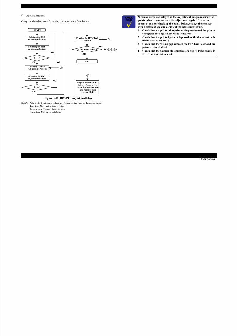
8/22/2019 TX 700 800
http://slidepdf.com/reader/full/tx-700-800 212/234
ADJUSTMENT Adjustment by Using Adjustment Program (TBD) 212
Confidential
Figure 5-12. BRS/PFP Adjustment Flow
Note*: When a PFP pattern is judged as NG, repeat the steps as described below.
First time NG: retry from step
Second time NG:retry from step
Third time NG: perform step
locate the defective partand replace, then
reassemble it.OK
Error?
EPSON Artisan 800/EPSON Stylus Photo PX800FW/TX800FW/Artisan 700/EPSON Stylus Photo PX700W/TX700W Revision A
5.2.8.1 BRS (Banding Reduction System) Adjustment
Printing the BRS Adjustment Pattern
1. Load A4 size Matte Paper-Heavyweight on the paper support.
2. Select [BRS Adjustment] in the adjustment program.
3. Click the [Print] button on the “1. Print Test Pattern” column to print the
adjustment pattern.
4. Let the printed pattern dry for more than 5 minutes if using CIS sensor type
scanner.
Scanning the BRS Adjustment Pattern
5. Set the printed pattern and the PFP Base Scale on the document table and click the
[Scan] button on the “3. Scan Test Pattern” column.
6. According to the scanned result, BRS calibration values are automatically
calculated and are written to the serial flash ROM. If an error occurs, check that
the document table glass and the scale is clean, and the scale/adjustment pattern is
not tilted, then repeat from step 5.
Printer IdentificationCode
Be careful of the following when setting the PFP Base Scale, and theadjustment pattern on the scanner.
Place the scale on the document glass aligning the scale corner
with the scanner origin position.
Place the pattern-printed sheet along the scale as shown in the
figure below. Make sure to place it parallel to the scale, with no
gaps.
Scanner Origin
Position
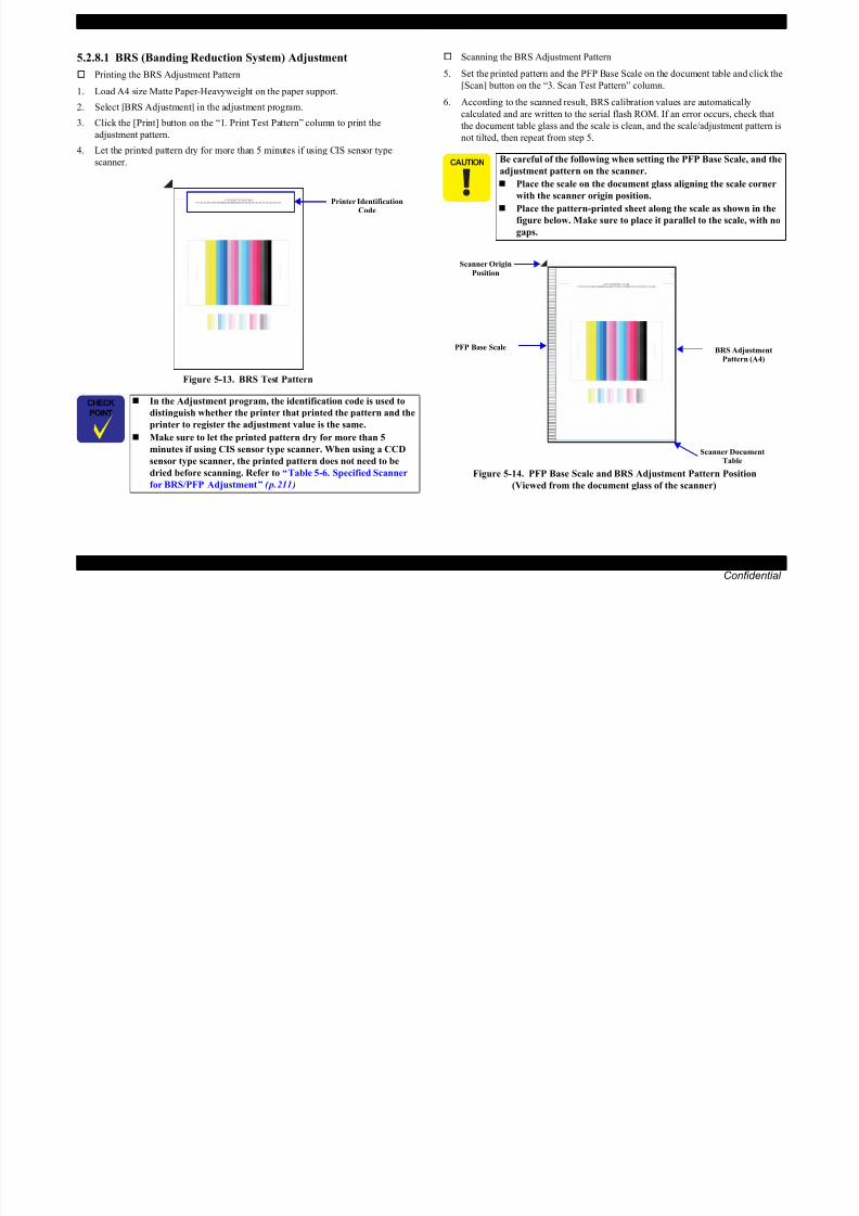
8/22/2019 TX 700 800
http://slidepdf.com/reader/full/tx-700-800 213/234
ADJUSTMENT Adjustment by Using Adjustment Program (TBD) 213
Confidential
Figure 5-13. BRS Test Pattern
Figure 5-14. PFP Base Scale and BRS Adjustment Pattern Position
(Viewed from the document glass of the scanner)
In the Adjustment program, the identification code is used to
distinguish whether the printer that printed the pattern and the
printer to register the adjustment value is the same.
Make sure to let the printed pattern dry for more than 5
minutes if using CIS sensor type scanner. When using a CCD
sensor type scanner, the printed pattern does not need to bedried before scanning. Refer to “ Table 5-6. Specified Scanner
for BRS/PFP Adjustment ” ( p. 211 )
BRS Adjustment
Pattern (A4)
Scanner DocumentTable
PFP Base Scale
EPSON Artisan 800/EPSON Stylus Photo PX800FW/TX800FW/Artisan 700/EPSON Stylus Photo PX700W/TX700W Revision A
5.2.8.2 PFP Adjustment
Printing the PFP Adjustment Pattern
1. Load 4 x 6 Premium Glossy Photo Paper on the paper support.
2. Select [PFP Adjustment] in the adjustment program.
3. Click the [Print] button on the “1. Print Test Pattern” column to print the
adjustment pattern.
Scanning the PFP Adjustment Pattern
4. Set the PFP Base Scale and the PFP test pattern on the document table and click
the [Scan] button on the “3. Scan Test Pattern” column.
5. According to the scanned result, PFP calibration values are automatically
calculated and are written to the serial flash ROM. If an error occurs, check that
the document table glass and the scale is clean, and the scale/adjustment pattern is
not tilted, then repeat from step 4.
P i Id ifi i
Be careful of the following when setting the PFP Base Scale and theadjustment pattern on the scanner.
Place the scale on the document glass aligning the scale corner
with the scanner origin position.
Place the pattern-printed sheet along the scale as shown in the
figure below. Make sure to place it parallel to the scale, with no
gaps.
Scanner OriginPosition

8/22/2019 TX 700 800
http://slidepdf.com/reader/full/tx-700-800 214/234
ADJUSTMENT Adjustment by Using Adjustment Program (TBD) 214
Confidential
Figure 5-15. PFP Test Pattern
Figure 5-16. PFP Base Scale and PFP Adjustment Pattern Position
(When viewed from the document glass of the scanner)
In the Adjustment program, the identification code is used to
distinguish whether the printer that printed the pattern and the
printer to register the adjustment value is the same.
Printer IdentificationCode
PFP Adjustment
Pattern(4 x 6 size)
Scanner DocumentTable
PFP Base Scale
EPSON Artisan 800/EPSON Stylus Photo PX800FW/TX800FW/Artisan 700/EPSON Stylus Photo PX700W/TX700W Revision A
Printing the PFP Check Pattern
6. Set 4 x 6 Premium Glossy Photo Paper on the paper support and click the [Print]
Button on the “4. Print Check Pattern” column.
Figure 5-17. PFP Check Pattern
Judging the Check Pattern
7. Referring to Figure 5-18 check that there is no white or overlapped bands in all the
check patterns. If any bands are found, carry out the steps below.
1. Re-print the check pattern to see if the bands appear again.
2. When bands appear in Step 1, try the PFP adjustment again from the
beginning.
3. When bands appear even after the re- adjustment in step 2, determine that it is
the mechanism failure and carry out check/reassemble of the parts that was
removed/replaced.Normal Area CheckPattern
Bottom Edge Area
Check Pattern
OK no bands
Normal Area Check
PatternBottom Edge Area
Check Pattern
NGhit b d

8/22/2019 TX 700 800
http://slidepdf.com/reader/full/tx-700-800 215/234
ADJUSTMENT Adjustment by Using Adjustment Program (TBD) 215
Confidential
Figure 5-18. PFP Check Pattern Judging Standard
white band
NGoverlapped band
EPSON Artisan 800/EPSON Stylus Photo PX800FW/TX800FW/Artisan 700/EPSON Stylus Photo PX700W/TX700W Revision A
5.3 Adjustment without Using AdjustmentProgram
This section explains the adjustment procedure without using the adjustment program.
5.3.1 PG Adjustment (TBD)
Described below is the platen gap (PG) adjustment.
Purpose:
Adjust the distance between the head surface and the Paper Guide Front Assy
(platen) properly and adjust the parallelism on the 0th column side and on the 80th
columns side to ensure reliable print quality.
Once the Carriage Assy and/or Adjustment Bushes have been removed or
whenever necessary for any other reason, make this adjustment to correct the
deviation of the platen gap.
Tools
Thickness gauge: 1.15 mm (x2)
1.3 mm (x2)
Phillips screwdriver
Standard value
Specified PG value: 1.2 ± 0.1 mm
Table 5-7. PG Positions
PositionPG Size
(mm)
Application for Printing
(selected from PG flag list for
normal/head rubbing))
Sequence Application
PG-Applied while capping, wiping
operations during standby after
The thickness gauge to be used must be free from dust and dirt
and from deformation. Be sure to clean it before use.
Take care that the Printhead is not soiled or scratched.
Move the carriage right and left by pulling the belt without
holding the carriage.
Carry out this adjustment with installing the Printhead, the Ink
Supply Tube Assy and the Cartridge Box Unit. (Install the CR
Scale after this adjustment) See “ 4.2.3 Disassembling the
Printer Mechanism (p118) ” .
EPSON Artisan 800/EPSON Stylus Photo PX800FW/
TX800FW/Artisan 700/EPSON Stylus Photo PX700W/TX700W
have five PG pre-settings using the APG mechanism. Use the
minimum PG setting (PG –: 1.2mm) to carry out this

8/22/2019 TX 700 800
http://slidepdf.com/reader/full/tx-700-800 216/234
ADJUSTMENT Adjustment without Using Adjustment Program 216
Confidential
PG
<APG Home>1.2 EPSON special paper
operations, during standby after
power-on, performing AID
adjustment.
PG typ.
<Mechanicaldefault>
1.7
Plain paper
Select when PG- is too narrow Applied while capping
PG+ 2.35
Envelopes
Select when PG typ. is too
narrow
Applied while capping
PG++ 2.95 CD/DVDApplied while capping
Applied while EJ release operation
adjustment.
See Figure. 5-19.
EPSON Artisan 800/EPSON Stylus Photo PX800FW/TX800FW/Artisan 700/EPSON Stylus Photo PX700W/TX700W Revision A
Adjustment procedure
1. Check that the carriage is in the PG-position. ( Fig. 5-19 )
2. Move the carriage to the center of the platen, and place a 1.15 mm thickness gauge
aligning its left edge with the first rib from the left end of the Front Paper Guide to the
seventh rib. Then place another 1.15 mm thickness gauge aligning its right edge with
the first rib from the right end of the Front Paper Guide to the fifth rib. ( Fig. 5-20 )
Left side
Right side
Gauge (1.15 or 1.3mm) placement
Right side
Gauge (1.15 or 1.3mm) placement
Left side

8/22/2019 TX 700 800
http://slidepdf.com/reader/full/tx-700-800 217/234
ADJUSTMENT Adjustment without Using Adjustment Program 217
Confidential
Figure 5-19. PG position when adjusting
Figure 5-20. Setting the thickness gauge
EPSON Artisan 800/EPSON Stylus Photo PX800FW/TX800FW/Artisan 700/EPSON Stylus Photo PX700W/TX700W Revision A
3. Pull the Timing Belt to move the carriage to the left end.
4. If the carriage comes in contact with the gauge, adjust the left parallelism bush to
raise the carriage until the Printhead does not touch the gauge.
5. Pull the Timing Belt to move the carriage to the right end.
6. If the carriage comes in contact with the gauge, adjust the right parallelism bush to
raise the carriage until the Printhead does not touch the gauge
Figure 5-22. PG adjustment (Left side)
When carrying out the next steps, take care of the following point.
Adjust the left/right sides of the Bush so as to let the sides of the
nozzle surface of the Printhead touch the gauge horizontally.
Figure 5-21. Caution about the PG adjustment
Basically move the same amount of scale for the front side as
that for the main shaft.
OK NGCarriage
Printhead P r int head
Car r iag e
Thickness GaugeThickness Gauge
Front Paper GuideFront Paper GuideFront
A
A
B
B
C
C
D
D
A
CD
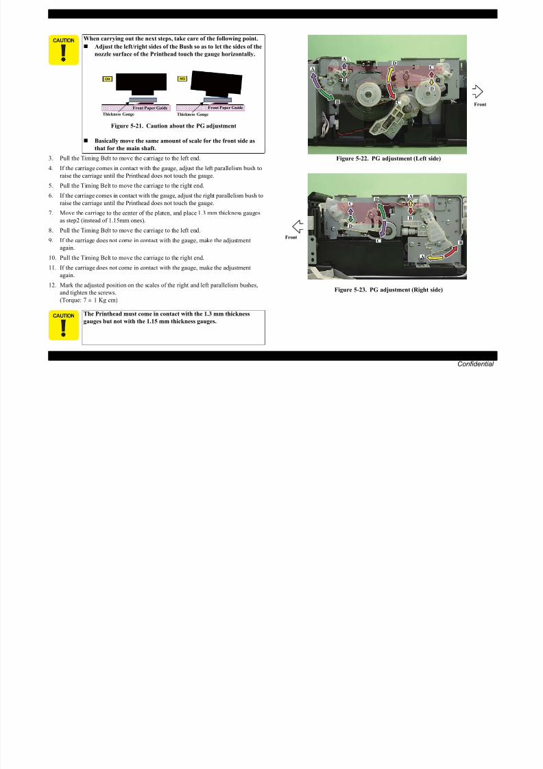
8/22/2019 TX 700 800
http://slidepdf.com/reader/full/tx-700-800 218/234
ADJUSTMENT Adjustment without Using Adjustment Program 218
Confidential
raise the carriage until the Printhead does not touch the gauge.
7. Move the carriage to the center of the platen, and place 1.3 mm thickness gauges
as step2 (instead of 1.15mm ones).
8. Pull the Timing Belt to move the carriage to the left end.
9. If the carriage does not come in contact with the gauge, make the adjustment
again.
10. Pull the Timing Belt to move the carriage to the right end.
11. If the carriage does not come in contact with the gauge, make the adjustment
again.
12. Mark the adjusted position on the scales of the right and left parallelism bushes,
and tighten the screws. (Torque: 7 ± 1 Kg cm)
Figure 5-23. PG adjustment (Right side)
The Printhead must come in contact with the 1.3 mm thickness
gauges but not with the 1.15 mm thickness gauges.
Front
A
B
B
C
C
D
EPSON Artisan 800/EPSON Stylus Photo PX800FW/TX800FW/Artisan 700/EPSON Stylus Photo PX700W/TX700W Revision A
5.3.2 CR Timing Belt Tension Adjustment
This section describes CR Timing Belt tension adjustment.
Purpose
This adjustment is made when the CR Timing Belt is removed, re-installed, or
loosened. Confirm that the belt tension is proper when the CR Timing Belt is
installed.
Things to be used
Tension gauge
Plastic Tweezers
Standard value
T.B.D
Adjustment procedure
1. Set the following parameters to the tension gauge:
• Weight: 1.0
• Width: 4.0
• Span: 310
2. Bring the microphone closer to the center of the Timing Belt.
3. Press the “MEASURE” button on the Tension gauge and flip the Timing Belt with plastic tweezers.
4. Repeat the steps three times and confirm that the measured values are within the
standard. If not, replace the Mechanism Unit.
Within 5mm

8/22/2019 TX 700 800
http://slidepdf.com/reader/full/tx-700-800 219/234
ADJUSTMENT Adjustment without Using Adjustment Program 219
Confidential
Figure 5-24. Preparation
Bring the microphone within 5mm from the Timing Belt but do not
let it touch the belt.
Flip the belt as weak as the tension gauge can measure it.
Be careful not to damage the Timing belt when flipping it with
the plastic tweezers.
Be careful not to let the microphone touch the Timing Belt when
flipping the belt.
EPSON Artisan 800/EPSON Stylus Photo PX800FW/TX800FW/Artisan 700/EPSON Stylus Photo PX700W/TX700W Revision A
5.3.3 PF Timing Belt Tension Adjustment
This section describes PF Timing Belt tension adjustment.
Purpose
This adjustment is made when the PF Timing Belt is removed, re-installed, or
loosened. Confirm that the belt tension is proper when the PF Timing Belt is
installed.
Things to be used
Tension gauge
Plastic Tweezers
Standard value
T.B.D
Adjustment procedure
1. Move the carriage to the home position.
2. Set the following parameters to the tension gauge:
• Weight: 0.9
• Width: 3.0
• Span: 73
4. Press the “MEASURE” button on the Tension gauge and flip the Timing Belt with plastic tweezers.
5. Repeat the steps three times and confirm that the measured values are within the
standard. If not, replace the Mechanism Unit.
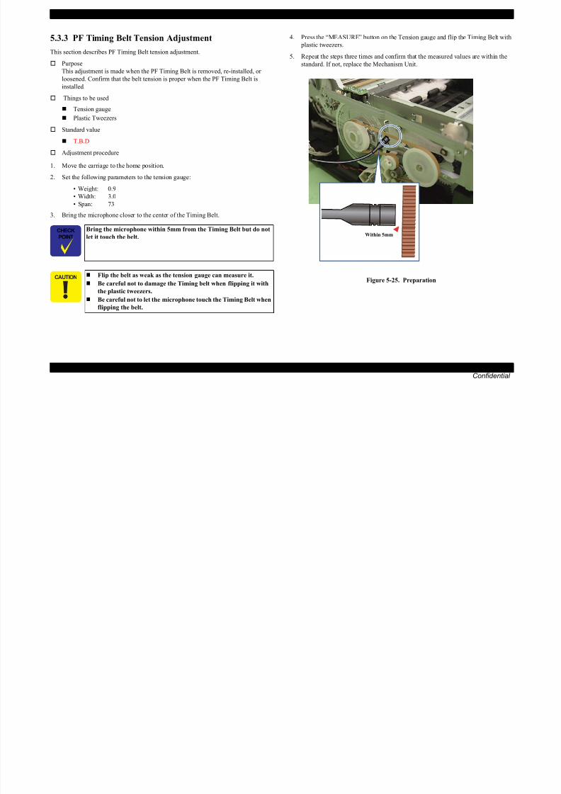
8/22/2019 TX 700 800
http://slidepdf.com/reader/full/tx-700-800 220/234
ADJUSTMENT Adjustment without Using Adjustment Program 220
Confidential
3. Bring the microphone closer to the center of the Timing Belt.
Figure 5-25. Preparation
Bring the microphone within 5mm from the Timing Belt but do not
let it touch the belt.
Flip the belt as weak as the tension gauge can measure it.
Be careful not to damage the Timing belt when flipping it with
the plastic tweezers.
Be careful not to let the microphone touch the Timing Belt when
flipping the belt.
Within 5mm
EPSON Artisan 800/EPSON Stylus Photo PX800FW/TX800FW/Artisan 700/EPSON Stylus Photo PX700W/TX700W Revision A
5.3.4 Touch Panel Adjustment (EPSON Artisan 800/EPSON Stylus Photo PX800FW/TX800FW only)(TBD)
This section describes Touch Panel adjustment.
Purpose
This adjustment is made to adjust the relative positions between the Touch Panel
screen and its detection coordinates.
Things to be used
Touch pen (without a sharp end such as a plastic stick)
Adjustment procedure
1. Turn the power on while pressing the panel within the frame on the left side and
“CD/DVD Tray” button at the same time for three seconds to enter the special
inspection mode.
7. Press “+” that displays on the center of the panel with the touch pen.
8. After “Complete!” is displayed on the screen, press “CD/DVD Tray” button and
return to the menu.
Power Left side of the touch panel
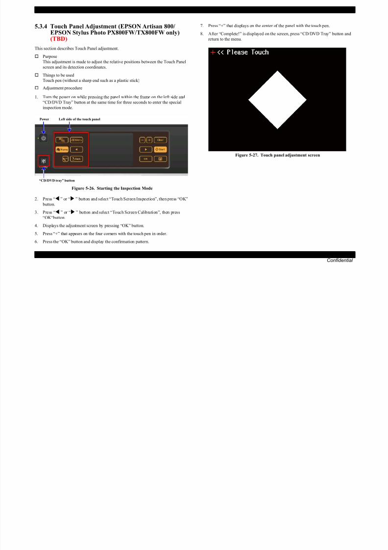
8/22/2019 TX 700 800
http://slidepdf.com/reader/full/tx-700-800 221/234
ADJUSTMENT Adjustment without Using Adjustment Program 221
Confidential
Figure 5-26. Starting the Inspection Mode
2. Press “ ” or “ ” button and select “Touch Screen Inspection”, then press “OK”
button.
3. Press “ ” or “ ” button and select “Touch Screen Calibration”, then press“OK“button.
4. Displays the adjustment screen by pressing “OK” button.
5. Press “+” that appears on the four corners with the touch pen in order.
6. Press the “OK” button and display the confirmation pattern.
Figure 5-27. Touch panel adjustment screen
“CD/DVD tray” button
C H A P T E R
6MAINTENANCE

8/22/2019 TX 700 800
http://slidepdf.com/reader/full/tx-700-800 222/234
Confidential

8/22/2019 TX 700 800
http://slidepdf.com/reader/full/tx-700-800 223/234
EPSON Artisan 800/EPSON Stylus Photo PX800FW/TX800FW/Artisan 700/EPSON Stylus Photo PX700W/TX700W Revision A
6.1.2.2 Service CallInk is consumed also for cleaning and flushing operations. When the ink is used for clean-
ing and flushing operations, the ink is drained to the Waste Ink Pads (Ink Waste Tray Assy)
via the Pump. The ink flushed outside of the boundary of paper when carrying out the bor-
derless printing is conducted through the Front Paper Guide Waste Ink Pad, and drained to
the Lower Paper Guide Waste Ink Pad Assy. The amount of the waste ink is stored as the waste ink counter into the EEPROM. When the
waste ink counter has reached the limit of the absorbing capability of the Waste Ink Pads,
the maintenance request error is displayed. This printer takes the ink evaporation amount
into consideration, therefore the counter limit differs depending on how often printing is
made.
When the maintenance request error appears, replace the Waste ink pads (Ink Waste Tray
Assy) with a new one and reset the waste ink counter using the Adjustment program. If the
waste ink counter is close to its limit, recommend that the Waste ink pads (Ink Waste Tray
Assy) will be replaced with new one. This is because the “Maintenance request error” will
may occur after returning the repaired product to the customer
6.1.3 Lubrication
The type and amount of the grease used to lubricate the printer parts are determined
based on the results of the internal evaluations. Be sure to apply the specified type and
amount of the grease to the specified parts during servicing mentioned below.
When a part that need lubrication is replaced
As the need arises during disassembly/reassembly of the printer
For display of Maintenance request error, see the following.
Chapter 3 TROUBLESHOOTING (p.50)
Never use oil or grease other than those specified in thismanual. Use of different types of oil or grease may damage the
component and adversely affect the printer operation.
Observe the specified amount. Never apply excess.
Type Name EPSON CODE Supplier
Grease G-71 1304682 EPSON
Grease G-74 1409257 EPSON

8/22/2019 TX 700 800
http://slidepdf.com/reader/full/tx-700-800 224/234
MAINTENANCE Overview 224
Confidential
may occur after returning the repaired product to the customer.
EPSON Artisan 800/EPSON Stylus Photo PX800FW/TX800FW/Artisan 700/EPSON Stylus Photo PX700W/TX700W Revision A
Refer to the following figures for the lubrication points.
Figure 6-2. Lubrication of the Left PG Cam and Right PG Cam
<Lubrication Points>
1. Two contact points between
the Carriage Unit and the CR
shaft.
2. Two contact points between
the Carriage Unit and the CR
guide plate.
3. Two lubrication holes on top ofthe Carriage Unit.
<Type>
G-71
<Application Amount>
1. 100 ± 20 mg
2. 170 ± 20 mg
3. 190 ± 20 mg
<Application Timing>
After installing the Carriage Unit
and the CR Shaft
<Remarks>
Apply with injector
Apply the grease through the holes. (x2)
CR shaft
Carriage Unit
Application PointCR guide plate
<Lubrication Points>
1. Contact points between the PGCam L and Left Parallelism
Bushing
2. Contact points between the PGCam R and Right Parallelism
Bushing
<Type>
G-71
<Application Amount>
1. φ 1 x sliding surface
2. φ 1 x sliding surface
<Application Timing>
After installing the PG Cam L and
the PG Cam R
<Remarks>Apply with injector
<Lubrication Points>
PG Cam L
Left Parallelism Bushing
Right Parallelism BushingPG Cam R
Application Point

8/22/2019 TX 700 800
http://slidepdf.com/reader/full/tx-700-800 225/234
MAINTENANCE Overview 225
Confidential
Figure 6-1. Lubrication of the CR Shaft and CR guide plate
Figure 6-3. Lubrication of the Left Front PG Cam and Right Front PG Cam
pp y j
1. After lubrication, move the
Carriage Unit from side to side
while rotating the CR shaft to
spread the grease evenly.
<Lubrication Points>
1. Sliding surface of the Left
Front PG Cam
2. Sliding surface of the RightFront PG Cam
<Type>
G-71
<Application Amount>
1. φ 1 x sliding surface
2. φ 1 x sliding surface
<Application Timing>Before installing the Left FrontPG Cam and Right Front PG Cam
<Remarks>
Apply with injector
Left Front PG Cam
Right Front PG Cam
Application Point
EPSON Artisan 800/EPSON Stylus Photo PX800FW/TX800FW/Artisan 700/EPSON Stylus Photo PX700W/TX700W Revision A
Figure 6-4. Lubrication of the Driven Pulley Assy Figure 6-6. Lubrication of the Paper Guide Front Assy
<Lubrication Points>
1. Four contact points between
the Driven Pulley Holder and
the Main Frame
2. The center of the Driven Pulley
(bushing)
<Type>
G-71
<Application Amount>
1. φ 1 x sufficient quantity
2. φ 1 x 1 mm
<Application Timing>
Before installing the Driven
Pulley Assy
<Remarks>
Apply with injector
<Lubrication Points>
The centers of the Driven Pulleys
Driven Pulley Holder
Driven Pulley
Application Point
<Lubrication Points>
Seven contact points between the
bushings of the Paper Guide Front
Assy and EJ Roller Shaft/PF
Roller Shaft.
<Type>
G-71
<Application Amount>φ 1 x sufficient quantity
<Application Timing>
Before installing the Paper Guide
Front Assy
<Remarks>
Apply with brush
<Lubrication Points>
1 Two points at the slits of the
Application Point

8/22/2019 TX 700 800
http://slidepdf.com/reader/full/tx-700-800 226/234
MAINTENANCE Overview 226
Confidential
Figure 6-5. Lubrication of the Driven Pulley Timing Assy
Figure 6-7. Lubrication of the Sub Cassette Slider
The centers of the Driven Pulleys
(bushings) (x2)
<Type>
G-71
<Application Amount>
φ 1 x 1 mm
<Application Timing>
Before installing the Driven
Pulley Timing Assy
<Remarks>Apply with injector
Driven Pulleys
Application Point
1. Two points at the slits of the
Sub Cassette Slider
2. Two points at the bearings of
the Sub Cassette Slider
<Type>
G-74
<Application Amount>
Sufficient quantity
<Application Timing>
Before installing the Cassette
Assy
<Remarks>
Apply with brush
Sub Cassette Slider
Application Point
EPSON Artisan 800/EPSON Stylus Photo PX800FW/TX800FW/Artisan 700/EPSON Stylus Photo PX700W/TX700W Revision A
Figure 6-9. Lubrication of the EJ Release Frame Assy L
<Lubrication Points>
1. Two contact points between
the EJ Frame Assy and the
Paper Guide Front Assy
2. Contact point between the left
side of EJ Frame Assy L and
the EJ Release Frame Assy L
3. Spur Gear 8.8 (L/R) (x2)
4. Toothed areas of EJ ReleaseRack (L/R) (x2)
<Type>
G-71
<Application Amount>
1. φ 2 x sufficient quantity
2. Sufficient quantity
3. φ 1 x 1 circle
4. φ 1 x toothed areas
<Application Timing>
(1), (2) Before installing the EJ
Frame Assy
(3), (4) Before installing the EJ
R l F A L/R
11
Bottom of the EJ Frame Assy EJ Frame Assy
2
Left of the EJ Frame Assy
EJ Frame Assy
3
4
Left side Spur Gear 8.8
<Lubrication Points>
Contact point between the EJ
Release Frame Assy L and the EJ
Release Slider Frame
<Type>
G-71
<Application Amount>
Sufficient quantity
<Application Timing>
Before installing the EJ Release
Frame Assy L
<Remarks>
Apply with brush
<Lubrication Points>
1. On the shaft of Spur Gear 15.2
2. On the toothed area of Spur
Gear 26.4
EJ Release Frame Assy L
EJ Release Slider Frame
Application Point
Spur Gear 15.2

8/22/2019 TX 700 800
http://slidepdf.com/reader/full/tx-700-800 227/234
MAINTENANCE Overview 227
Confidential
Figure 6-8. Lubrication of the EJ Release Assy L/R and EJ Release RacksFigure 6-10. Lubrication of the Spur Gear 15.2 and Spur Gear 26.4
Release Frame Assy L/R
<Remarks>
Apply with injector EJ Release Rack
3
4
Right side
EJ Release Rack Application Point
Spur Gear 8.8
<Type>
G-71
<Application Amount>
1. φ 1 x 1 circle
2. φ 1 x half circle
<Application Timing>
Before installing the CDR Tray
<Remarks>
Apply with injector
Application Point
CDR Tray
Spur Gear 26.4
Application Point
EPSON Artisan 800/EPSON Stylus Photo PX800FW/TX800FW/Artisan 700/EPSON Stylus Photo PX700W/TX700W Revision A
<Lubrication Points>
1. Ten contact points between the
Intermediate Roller shaft and the
Lower ASF Paper Guide Assy
2. On the shaft of Spur Gear 26
<Type>
G-71
<Application Amount>1. φ 1 x 1 circle
2. φ 1 x 1 circle
<Application Timing>
Before installing the Lower ASF
Paper Guide Assy
<Remarks>
Apply with injector
Intermediate Roller shaft
Lower ASF Paper Guide Assy
Application Point
Lower ASF Paper Guide Assy
Spur Gear 26
<Lubrication Points>
1. Five points on the shafts of the
Main Frame and APG Holder
Assy
2. On the toothed areas of the
Spur Gear A, B, C and
Combination Gear A, B
<Type>
G-71
<Application Amount>
1. φ 1 x 1 circle
2. φ 1 x half circle
<Application Timing>
Before installing each gear
<Remarks>
Apply with injector
Spur Gear C
Spur Gear B
Spur Gear A
Combination Gear A
Main Frame
APG HolderAssy
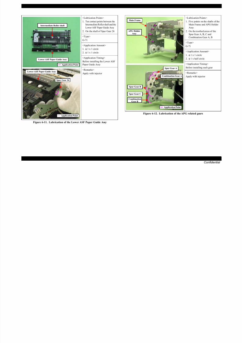
8/22/2019 TX 700 800
http://slidepdf.com/reader/full/tx-700-800 228/234
MAINTENANCE Overview 228
Confidential
Figure 6-11. Lubrication of the Lower ASF Paper Guide Assy
Figure 6-12. Lubrication of the APG related gearsApplication Point
Spur Gear C
CombinationGear B
Application Point
EPSON Artisan 800/EPSON Stylus Photo PX800FW/TX800FW/Artisan 700/EPSON Stylus Photo PX700W/TX700W Revision A
Figure 6-13. Lubrication of the Transmission Holder Assy (1)
Figure 6-15. Lubrication of the Spur Gear 17.6
<Lubrication Points>
1. Four contact points between
the Transmission Holder Assy
and the Transmission Gears
2. Contact point between the Spur
Gear 13.6 and the
Transmission Holder Assy
<Type>
G-71
<Application Amount>
1. φ 1 x 1 circle
2. φ 1 x 1 circle
<Application Timing>
Before installing each gear
<Remarks>
Apply with injector
<Lubrication Points>
Spur Gear13.6
Transmission Gears
Transmission Holder Assy
Application Point
<Lubrication Points>
Four contact points between the
Spur Gear 17.6 and the EJ Release
Trigger
<Type>
G-74
<Application Amount>
Ribs of the Spur Gear 17.6 x 4 points
<Application Timing>
Before installing the Transmission
Arm
<Remarks>
Apply with injector
<Lubrication Points>
Five contact points between the
Tensioner and the Tension Holder
reinforcing plate
EJ Release Trigger
Spur Gear 17.6
Application Point
Tensioner
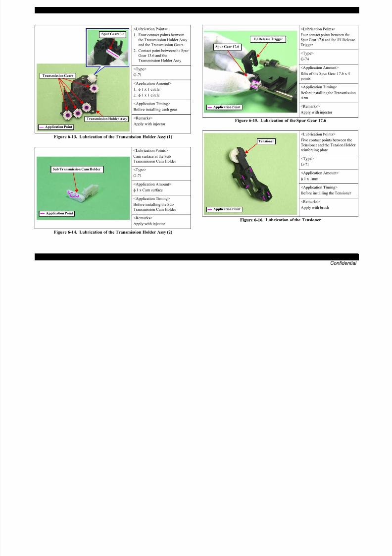
8/22/2019 TX 700 800
http://slidepdf.com/reader/full/tx-700-800 229/234
MAINTENANCE Overview 229
Confidential
Figure 6-14. Lubrication of the Transmission Holder Assy (2)
Figure 6-16. Lubrication of the Tensioner
Cam surface at the Sub
Transmission Cam Holder
<Type>
G-71
<Application Amount>
φ 1 x Cam surface
<Application Timing>
Before installing the Sub
Transmission Cam Holder
<Remarks>
Apply with injector
Sub Transmission Cam Holder
Application Point
<Type>
G-71
<Application Amount>
φ 1 x 1mm
<Application Timing>
Before installing the Tensioner
<Remarks>
Apply with brushApplication Point
EPSON Artisan 800/EPSON Stylus Photo PX800FW/TX800FW/Artisan 700/EPSON Stylus Photo PX700W/TX700W Revision A
Figure 6-17. Lubrication of the Pick Up Roller transmission shaft
Figure 6-19. Lubrication of the LD Roller shaft
<Lubrication Points>
1. Two toothed areas of the Pick
Up Roller transmission shaft
2. Two contact points between
the Pick Up Roller and Pick Up
Frame
3. Three contact points between
the Pick Up Roller
transmission shaft and Pick Up
Frame
<Type>
G-74
<Application Amount>
Sufficient quantity
<Application Timing>
Before installing the Pick UpRoller
<Remarks>
Apply with injector
Pick Up Rollertransmission shaft
Pick Up Roller Application Point
<Lubrication Points>
Two Contact points between the
LD Roller shaft and the Base
Frame
<Type>
G-71
<Application Amount>
φ 1 x 1 circle
<Application Timing>
Before installing the LD Roller
shaft
<Remarks>
Apply with injector
<Lubrication Points>
Two contact points between the
Intermediate Roller shaft and the
Base Frame
<Type>
LD Roller shaft
Application Point
Intermediate Roller shaft

8/22/2019 TX 700 800
http://slidepdf.com/reader/full/tx-700-800 230/234
MAINTENANCE Overview 230
Confidential
Figure 6-18. Lubrication of the Spur Gear 36
Figure 6-20. Lubrication of the Intermediate Roller Shaft
<Lubrication Points>
1. On half the toothed area of theSpur Gear 36
2. On the shaft of the Base Frame
<Type>
G-71
<Application Amount>
Sufficient quantity
<Application Timing>Before installing the CDR Guide
<Remarks>
Apply with injector
Spur Gear 36
Application Point Base Frame
<Type>
G-71
<Application Amount>φ 1 x 1 circle
<Application Timing>
Before installing the Intermediate
Roller shaft
<Remarks>
Apply with injector
Intermediate Roller shaft
Application Point
EPSON Artisan 800/EPSON Stylus Photo PX800FW/TX800FW/Artisan 700/EPSON Stylus Photo PX700W/TX700W Revision A
Figure 6-21. Lubrication of the Frame Base
Figure 6-23. Lubrication of the Panel Unit (Artisan 700/PX700W/TX700W)
<Lubrication Points>
Contact points between the Frame
Base and the Combination Gear
A, B and Spur Gear A
<Type>
G-71
<Application Amount>
φ 1 x 1 circle
<Application Timing>
Before installing the LD Roller
Shaft and the Intermediate Roller
Shaft
<Remarks>
Apply with injector
<Lubrication Points>
On the CDR Guide
<Type>
G-74
Application Point
Spur GearA’s shaft
Combination
Gear A’s shaft
CombinationGear B’s shaft
CDR Guide
<Lubrication Points>
On the shaft of the Panel Unit
(3mm away from the left end)
<Type>
G-71
<Application Amount>
φ 1 x 10mm
<Application Timing>
Before installing the Panel Unit
<Remarks>
Apply with injector Application Point
Panel Unit
3mm

8/22/2019 TX 700 800
http://slidepdf.com/reader/full/tx-700-800 231/234
MAINTENANCE Overview 231
Confidential
Figure 6-22. Lubrication of the CDR Guide
G 74
<Application Amount>
Sufficient quantity all along
<Application Timing>
Before installing the CDR Guide
<Remarks>
Apply with injector Application Point
C H A P T E R
7APPENDIX

8/22/2019 TX 700 800
http://slidepdf.com/reader/full/tx-700-800 232/234
Confidential
EPSON Artisan 800/EPSON Stylus Photo PX800FW/TX800FW/Artisan 700/EPSON Stylus Photo PX700W/TX700W Revision A
7.1 Connector SummaryThis section shows the connections between the main components of the printer.
CA29 MAIN
CA29 PSB
Printhead
PW Sensor CR Encoder
B
M
Y
Carriage Assy
AC inCN2
CN501CN1
CN2
CN3
CN4
CN6
CN5
CN1
CN1CSIC
CR Contact ModuleLM
C
LC
CN1
CN36
CA29 IF-B LINE Port CN20
CN21 EXT Port
Photo Tray Sensor CN12
CA29 PNL
CN33CN1
CN3 Touch panel
CN2 3.5 inch LCD Module
CN5 SUB-C Board
CIS ModuleCN41
Scanner Encoder
Scanner Motor
CN49
Scanner Unit
CN25
CN51
DOC Sensor
ADF Motor
ADF Unit
Scanner Open Sensor CN10
PE Sensor
Operation Panel Unit
CN4
EPSON Artisan800/ EPSON Stylus Photo PX800FW/ EPSON Stylus Photo TX800FW
EPSON Artisan800/ EPSON Stylus Photo PX800FW/
EPSON Stylus Photo TX800FW
Only
Only
EPSON Artisan800/ EPSON Stylus Photo PX800FW/ EPSON Stylus Photo TX800FW
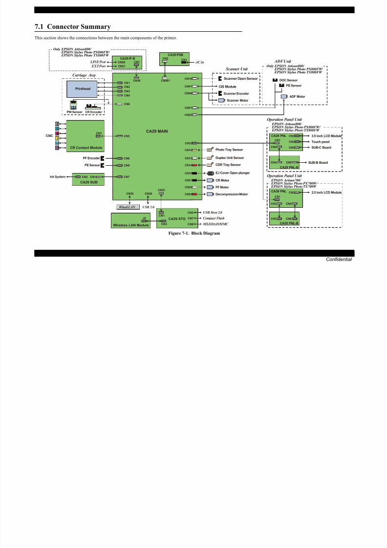
8/22/2019 TX 700 800
http://slidepdf.com/reader/full/tx-700-800 233/234
APPENDIX Connector Summary 233
Confidential
Figure 7-1. Block Diagram
PF Encoder
CN7CN1CN2
CA29 SUB
Ink System
CN8
PE Sensor CN9
CN30
EJ Cover Open plunger
PF Motor CN22
CN19
CR Motor CN21
Decompression Motor CN24
Duplex Unit Sensor CN13
CDR Tray Sensor CN14
Wired LAN
CN31
USB 2.0
CN1
CA29 STG CN7 Compact Flash
CN8 MS/SD/xD/MMC
CN2 USB Host 2.0
CN3Wireless LAN Module
J2
CA29 PNL-B
SUB-B Board
CN35CA30 PNL
CN1
CN2 2.5 inch LCD Module
CA30 PNL-B
CN5 CN6
CN3 CN4
CN4 CN5
Operation Panel Unit EPSON Artisan700/ EPSON Stylus Photo PX700W/ EPSON Stylus Photo TX700W
EPSON Artisan 800/EPSON Stylus Photo PX800FW/TX800FW/Artisan 700/EPSON Stylus Photo PX700W/TX700W Revision A
7.2 Exploded Diagram / Parts ListThis manual does not provide exploded diagrams or parts list.
For the information, see SPI (Service Parts Information).

8/22/2019 TX 700 800
http://slidepdf.com/reader/full/tx-700-800 234/234
APPENDIX Exploded Diagram / Parts List 234
Confidential