tx8005 air xd group i hazardous locations
TRANSCRIPT

Use
r M
an
ua
l TX8005 Air XD Group I Hazardous Locations
Real-Time Dust Monitor
P5628.1601 Rev B Leading Safety Technology


Air XD User Manual
www.trolex.com P5628.1601 Rev B 2
TX8005 AIR XD Grp I Hazardous Locations
Contents General Description ................................................................................................................................................................................................ 4
1.1 Main features .................................................................................................................................................................................................................. 5 1.2 Performance Data .......................................................................................................................................................................................................... 5 1.3 Intended Use ................................................................................................................................................................................................................... 6 1.4 Limits of Use .................................................................................................................................................................................................................... 6
Product Safety ........................................................................................................................................................................................................... 7 Danger from Process .............................................................................................................................................................................................. 8 Safety Procedures ................................................................................................................................................................................................... 8
4.1 Laser Safety Precautions .............................................................................................................................................................................................. 9 System Components .............................................................................................................................................................................................. 10
5.1 TX8005 Group I Air XD Particulate Monitor ........................................................................................................................................................... 11 5.2 Particulate Flow Path ................................................................................................................................................................................................... 12 5.3 TX8805 Air XD USB Drive ......................................................................................................................................................................................... 13 5.4 Peripherals and Accessories ..................................................................................................................................................................................... 14
Certification and Conformity ................................................................................................................................................................................. 16 6.1 Underground Mines .................................................................................................................................................................................................... 16 6.2 Conditions of use: ......................................................................................................................................................................................................... 17
Technical information ............................................................................................................................................................................................. 18 7.1 Product Options ........................................................................................................................................................................................................... 18 7.2 Product Specification .................................................................................................................................................................................................. 18 7.3 Product Dimensions ................................................................................................................................................................................................... 20
Hardware Installation ............................................................................................................................................................................................. 21 8.1 Safety Precautions ....................................................................................................................................................................................................... 21 8.2 Mounting Details .......................................................................................................................................................................................................... 21 8.3 Main Parts ..................................................................................................................................................................................................................... 22 8.4 Electrical Connections ............................................................................................................................................................................................... 23 8.5 I/O Terminals ................................................................................................................................................................................................................ 24 8.6 Power Connections .................................................................................................................................................................................................... 24 8.7 RS485 – Output Signals ............................................................................................................................................................................................ 25 8.8 RS485 – Line Terminations ...................................................................................................................................................................................... 25
Commissioning ....................................................................................................................................................................................................... 26 9.1 First Power On ............................................................................................................................................................................................................. 26 9.2 Application Software .................................................................................................................................................................................................. 26
Controls and Indicators ........................................................................................................................................................................................ 27 10.1 Navigation ...................................................................................................................................................................................................................... 27 10.2 Main Function Keys .................................................................................................................................................................................................... 28 10.3 Short-cut Functions ..................................................................................................................................................................................................... 30
General Operation .................................................................................................................................................................................................. 31 11.1 User Interface Display ................................................................................................................................................................................................. 31 11.2 PM Value Display Map ............................................................................................................................................................................................... 32 11.3 Settings Structure ....................................................................................................................................................................................................... 33 11.4 PM Settings ................................................................................................................................................................................................................... 34 11.5 Setting custom PM values ......................................................................................................................................................................................... 34 11.6 PM Density .................................................................................................................................................................................................................... 35 11.7 Averaging Settings ..................................................................................................................................................................................................... 35 11.8 Alarm Settings .............................................................................................................................................................................................................. 36 11.9 Channel Select .............................................................................................................................................................................................................. 37 11.10 Threshold Channel ...................................................................................................................................................................................................... 37 11.11 Set Alarm Threshold ................................................................................................................................................................................................... 38 11.12 Alarm Latching ............................................................................................................................................................................................................. 38 11.13 Alarm Enable/Disable ................................................................................................................................................................................................. 39 11.14 4-20mA Outputs .......................................................................................................................................................................................................... 39 11.15 Select PM Channel ..................................................................................................................................................................................................... 40 11.16 Map 4-20mA to Data Channel ................................................................................................................................................................................. 40 11.17 Set Max PM Value ....................................................................................................................................................................................................... 40 11.18 Enable/Disable .............................................................................................................................................................................................................. 41 11.19 Status .............................................................................................................................................................................................................................. 41 11.20 Communications .......................................................................................................................................................................................................... 42 11.21 Ethernet Communications ......................................................................................................................................................................................... 42 11.22 Network Status ............................................................................................................................................................................................................ 42 11.23 IP Settings ..................................................................................................................................................................................................................... 42 11.24 Ethernet Operating Mode ......................................................................................................................................................................................... 43

www.trolex.com 3 P5628.1601 Rev B
11.25 Ethernet Connection Status...................................................................................................................................................................................... 43 11.26 RS485 MODBUS Communications ......................................................................................................................................................................... 44 11.27 Set Baud Rate .............................................................................................................................................................................................................. 44 11.28 Set Device Address .................................................................................................................................................................................................... 44 11.29 Display ........................................................................................................................................................................................................................... 45 11.30 Adjusting Display Contrast ....................................................................................................................................................................................... 45 11.31 Set Display Backlight.................................................................................................................................................................................................. 45 11.32 Set Display Colour ...................................................................................................................................................................................................... 46 11.33 Set Display Sleep ........................................................................................................................................................................................................ 46 11.34 Date & Time ................................................................................................................................................................................................................... 47 11.35 Set Date .......................................................................................................................................................................................................................... 47 11.36 Set Time ......................................................................................................................................................................................................................... 47 11.37 System ........................................................................................................................................................................................................................... 48 11.38 System Information ..................................................................................................................................................................................................... 48 11.39 Restart Controller ........................................................................................................................................................................................................ 48 11.40 Data Download ............................................................................................................................................................................................................ 49 11.41 Memory Module .......................................................................................................................................................................................................... 50 11.42 Firmware Update .......................................................................................................................................................................................................... 51
Instrument Configuration ...................................................................................................................................................................................... 52 12.1 Default Settings ........................................................................................................................................................................................................... 52 12.2 On-Site Configuration ................................................................................................................................................................................................ 52 12.3 MODBUS Addresses .................................................................................................................................................................................................. 53 12.4 Coil Register ................................................................................................................................................................................................................. 55 12.5 Holding Register .......................................................................................................................................................................................................... 56 12.6 Instrument Self-Test ....................................................................................................................................................................................................57
Maintenance ........................................................................................................................................................................................................... 58 13.1 Visual Checks .............................................................................................................................................................................................................. 58 13.2 Cleaning Labels ........................................................................................................................................................................................................... 58 13.3 Particulate Entry/Exit apertures ............................................................................................................................................................................... 58
Troubleshooting ..................................................................................................................................................................................................... 59 14.1 High Temperature operating .................................................................................................................................................................................... 59 14.2 Low Temperature Start-up ........................................................................................................................................................................................ 59 14.3 Fault Codes .................................................................................................................................................................................................................. 60
Glossary and Definitions ....................................................................................................................................................................................... 61 Disposal .................................................................................................................................................................................................................... 61
16.1 Waste of Electrical and Electronic Equipment (WEEE) Directive (2012/19/EU) .............................................................................................. 61 Technical Support ................................................................................................................................................................................................... 61 Disclaimers .............................................................................................................................................................................................................. 62 Revisions ................................................................................................................................................................................................................. 62 Feedback ................................................................................................................................................................................................................. 63 Trademarks ............................................................................................................................................................................................................. 63

Air XD User Manual
www.trolex.com P5628.1601 Rev B 4
1. General Description The Trolex Group I Air XD particulate monitor is designed to provide detailed, accurate, real-time data
on airborne particulates so that users can take appropriate actions to stay safe and ensure personnel
are fully protected from particulate-related health hazards. The Air XD allows users to simultaneously
monitor multiple Particulate Matter (PM) sizes (PM1.0, PM2.5, PM4.25, PM10 as well as custom) and can
report on Total Suspended Particulates (TSP). Precise data is collected for measurable particulates,
enabling detailed size profiling and analysis using the application software.
The Air XD uses an innovative Optical Particle Counter (OPC) that combines adaptive particle flowrate
with advanced sensing technology to ensure a high level of measurement accuracy. The size of each
particle is instantaneously measured and classified at up to 10,000 samples a second to allow detailed
real-time reporting in high dust environments.
As the Air XD records live data on all particulates between 0.35μm and 40μm, users can easily access
and view detailed information about a wide range of PM sizes. Measurement information can be viewed
via the instrument display or as a live or historical readings using the application software.
TX8005 Group I Air XD

www.trolex.com 5 P5628.1601 Rev B
Main features
• Real-time continuous measurement of atmospheric dust concentration • High-reliability, low-maintenance for high-dust environments • High capacity Optical Particulate Counter (OPC) • Industry Standard sizing PM1.0, PM2.5, PM4.25 and PM10 • Low-end resolution, measuring down to 0.35μm with 99.9% capture • Ability to display Total Suspended Particles (TSP) measurement reading • Quantification of particle size categories to customer requirements (Custom sizing) • Operational stability in varying environmental and atmospheric conditions • On-device display readout • Choice of display modes, ‘Live’ readout or configurable ‘Averages’ • Two configurable relay output contacts for remote alarms and control functions • Two 4-20mA analogue output signals of measured averages • Remote RS485 MODBUS RTU Serial I/O interface • Ethernet MODBUS TCP/IP output • High visibility alarm warning indicators • Plug and play installation
Performance Data
Using current advancements in light scattering techniques combined with patented data processing
algorithms, the Air XD is able to achieve levels of accuracy (+/-5%) normally only found in high-end
laboratory instruments.

Air XD User Manual
www.trolex.com P5628.1601 Rev B 6
Intended Use
The Air XD is a particulate monitor designed for use in range of hazardous applications and
environments. The instrument is suitable for monitoring in either indoor or outdoor ambient air conditions
and can cope with both high and low particulate concentration levels (up to 1500 mg/m3). The instrument
is designed to be low maintenance and does not use pumps or filters. The sensing element has an
adaptive flowrate to increase accuracy in environments with varying airflow.
Limits of Use
To ensure the optimum performance and safe operation, the Air XD must be operated as per the limits
detailed in the technical data section of this user manual. Operation outside these limits may result in
damage to the equipment or failure to achieve the performance specification.
Continual operation of the Air XD at extremes of the specified temperature limits may reduce the
operating lifetime of the product.
Trolex will not be liable for any injury or damage caused by incorrect installation, setup, operation or
maintenance resulting in a failure to follow the procedures and safety instructions provided in this user
manual.

www.trolex.com 7 P5628.1601 Rev B
2. Product Safety The following symbols are used in this manual or on the instrument to indicate procedures that, if not
followed correctly, may result in personal injury or damage to equipment.
WARNING!
Alerts the user to a potentially hazardous procedure or practice
which, if not followed correctly can result in serious personal injury
or injury of others.
CAUTION!
Alerts the user to a procedure or practice which, if not followed
correctly, can result in damage to the system or ancillary equipment.
In addition, the following symbols are used on the instrument:
WARNING! – ELECTRIC SHOCK RISK
WARNING! – LASER RADIATION
The use of controls, adjustments or procedures other than those
specified in this user manual may result in exposure to hazardous
optical radiation.

Air XD User Manual
www.trolex.com P5628.1601 Rev B 8
3. Danger from Process It is possible that the Air XD could be installed in environments that contain process particulates which
can be hazardous to health. These may take one or more of the following forms:
• Particulate that is inflammable or explosive
• Particulate which is toxic or some way hazardous to health
Unless process conditions are known to be entirely safe, suitable precautions such as the use of
breathing apparatus or environmental purging/detoxifying should be employed before entry is made
into the installation or maintenance environment.
4. Safety Procedures Always observe the safety precautions detailed in this user manual. Personnel installing, operating or
maintaining the equipment are responsible for their personal safety and correct handling of the
equipment in accordance with all safety instructions detailed.
Follow all warnings and instructions marked on the instrument. Warning labels are situated on the
instrument, indicating a hazard at or near the location of the warning label.
Retain these instructions in a safe and known place for future use.
The Air XD has been designed to be as simple to install and commission as possible. Nevertheless,
installation in working environments can be challenging and correct set up is critical to the function of
the instrument. It is important that you carefully read the entire User Manual before using and installing
the Air XD for the first time and keep it in a safe place for future reference.
Refer to the following standards for additional guidance:
• IEC/EN 60079-14
• IEC/EN 60079-25
Peripheral components such as the power supply and communications module/peripheral or interface
must be installed according to the manufacturer’s instructions and the installation location’s prevailing
statutory regulations.
The installation of the instrument must only be carried out by competent personnel. Each installation
needs to be considered with reference to the local safety regulations and authorities.
Refer to the Certification and Conformity section of this User Manual and to the relevant certificates for
any installation parameters and special conditions of safe use.
Observe the national safety regulations issued, for example, by the employers’ liability insurance
association, social security institutions, occupational safety and health authorities or other safety
organisations.

www.trolex.com 9 P5628.1601 Rev B
Laser Safety Precautions
The Air XD is rated via the Class 1 Laser safety guideline under all conditions of normal use. Class 1 laser products may contain laser systems of a higher class but there are adequate engineering control measures to ensure that access to the beam is not permitted during normal use. WARNING - Class 3B laser radiation when the laser housing is open,
do not open the laser housing. Eye damage may result from the direct viewing of the laser beam.
The Air XD complies with:
- IEC 60825-1 2014
- 21 CFR-1040.10 and 1040.11
Sensor Housing
WARNING: There are no user serviceable parts inside the Air XD sensor housing.
Servicing should only be carried out by Trolex or an approved service technician.

Air XD User Manual
www.trolex.com P5628.1601 Rev B 10
5. System Components The Air XD is typically installed as a stand-alone instrument for Group I underground mines and industrial applications. The instrument is supplied with peripherals fitted to allow for the plug and play
installation to IS power supplies, interface barriers and data outputs. The Air XD instrument and Air X software are specifically designed to work in conjunction with each other using proprietary protocols and design features. The system has also been designed to support 3rd party power supplies and communication protocols where required.
Example installation configuration
Note: M20 gland entries are provided for custom installation requirements. Gland entries may be
blanked, and installations may vary from diagram shown.
Ethernet or RS485
Comms
Windows PC
or Server
Air XD USB Drive
Interface Port
Air XD Group I
Comms Barrier
2 x Relay Output 2 x 4 to 20mA
IS Power Supply
Hazardous Environment
Non-Hazardous Environment

www.trolex.com 11 P5628.1601 Rev B
TX8005 Group I Air XD Particulate Monitor
The Air XD Particulate Monitor uses an Optical Particle Counter (OPC) that is located inside a robust stainless-steel housing. This provides isolation and ingress protection between the particle flow path and the main control circuits. Control circuits are housed in a lockable, IP66 rated coated steel
enclosure. Information and settings can be accessed using the keypad and display located on the front of the instrument. The Air XD can be configured to report on PM size concentrations or TSP based on user requirement, with the option of two configurable setpoint relay outputs. Detailed information can be transmitted via an RS485 or Ethernet connection to a computer running the accompanying application software or downloaded directly from the internal memory module using the certified Air XD USB storage drive. The figure below shows the location of the navigation buttons, display screen and status LEDs. Power and network connections enter the main housing via cable entry glands located on the bottom of the instrument. The Air XD can be wall or stand mounted via mounting brackets.
Particle Inlet
LCD Display
Status LEDs Door Lock
Navigation Buttons
Mounting
Brackets
M20 Cable
Entry Glands
Particle Outlet TX8805 Air XD USB
Drive interface

Air XD User Manual
www.trolex.com P5628.1601 Rev B 12
Particulate Flow Path
The Air XD has been designed with the ability to restrict ingress through the particulate flow path during
routine maintenance and cleaning periods. A rotational top cap is used to open or close the particle flow
path to provide increased ingress protection during cleaning.
It is recommended that the top cap is set to the closed position during instrument maintenance and
cleaning to ensure the dust sensor is not exposed to unnecessary ingress. When the top cap is rotated
into the closed position, the Air XD conforms to IPX6.
The Air XD can detect whether the flow path is open or closed and will record top cap positions to aid
with instrument maintenance schedules.
Open Flow Path Closed Flow Path
Rotate Dust Cap to Open and
Close particulate flow path Top Cap Open Top Cap Closed

www.trolex.com 13 P5628.1601 Rev B
TX8805 Air XD USB Drive
The Air XD USB Drive is designed to allow for the local download of recorded data within the hazardous environment from the Air XD. 8GB of memory is housed within a fully sealed enclosure which is encapsulated to meet IP66 requirements.
Once the download of data is complete from remote or isolated Air XD devices, the USB Drive can be locally connected to a surface PC for transfer and interrogation of the data using the Air XD application software. The USB Drive is externally connected to the Air XD instrument without the need to open the enclosure door via an IP66 M20 Panel Mounted USB bayonet connector located on the underside of the device. The Air XD USB Drive is not designed to be permanently connected to the Air XD and must be removed after data download/upload is complete. To ensure that IP integrity is maintained, IP protection caps must be replaced onto each USB connector shell after use. Note: The Instrument USB port operates at 4V, do not connect any other USB device to the Air XD when
located in a hazardous environment. USB drives with no power source (e.g. standard USB stick) may be
connected to the USB connector in the safe area for test purposes etc. Not all USB drives will operate
or be compatible with the Air XD instrument due to operational voltage differences.
Lanyard/Mounting
Ring
Captive USB
Cable
USB Bayonet
connector
Encapsulated
housing
Air XD User Manual
www.trolex.com P5628.1601 Rev B 14
Peripherals and Accessories
Power supply The Air XD must only be connected to an approved Intrinsically Safe (IS) 12 V DC power supply
approved for use in hazardous locations.
Ethernet Barrier Use of an approved Intrinsically Safe (IS) isolating Ethernet barrier is required to connect an Air XD device operating in the hazardous environment to a mine Ethernet network. Suitable hardware can be provided on request.
RS485 Barrier Use of an Intrinsically Safe (IS) RS485 barrier is required to connect an Air XD device operating in the hazardous environment to a mine network. Converters are also available to allow integration with Ethernet communications. Suitable hardware can be provided on request.
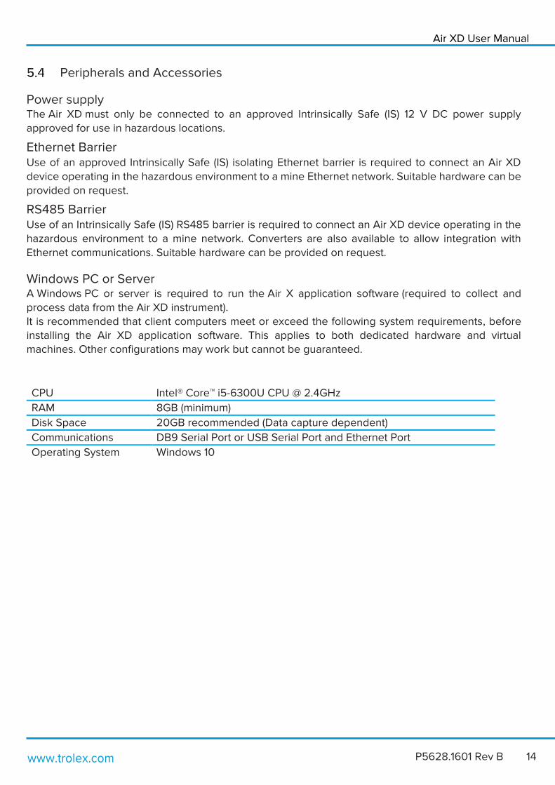
Windows PC or Server A Windows PC or server is required to run the Air X application software (required to collect and
process data from the Air XD instrument). It is recommended that client computers meet or exceed the following system requirements, before installing the Air XD application software. This applies to both dedicated hardware and virtual machines. Other configurations may work but cannot be guaranteed.
• CPU • Intel® Core™ i5-6300U CPU @ 2.4GHz
• RAM • 8GB (minimum)
• Disk Space • 20GB recommended (Data capture dependent)
• Communications • DB9 Serial Port or USB Serial Port and Ethernet Port
• Operating System • Windows 10

www.trolex.com 15 P5628.1601 Rev B
Air X Application Software
Data transmitted to a PC or server is collected, stored and processed using the Air X application software. The instrument communicates with the Air X software using MODBUS RTU (RS485). The Air X application software can be used to monitor in real-time or review historical data. It allows user to monitor instrument information, graph live data sets and monitor alarms. Note: Operating instructions for the application software are provided in a separate user manual.

Air XD User Manual
www.trolex.com P5628.1601 Rev B 16
6. Certification and Conformity
IECEx (International) certification for use in underground mines in Australia (including Queensland) and New Zealand.
Standards: IEC 60079-0:2017 Edition 7.0 IEC 60079-11:2011 Edition 6.0 IEC 60079-28:2015 Edition 2.0
ATEX certification for use in underground mines in European Union. Complies with the following EU Directives: ATEX Directive 2014/34/EU - EN IEC 60079-0:2018 - EN 60079-11:2012 - EN 60079-28:2015 EMC Directive 2014/30/EU - EN 61326-1:2013 - EN 61000-6-2:2019 - EN 61000-6-3:2007+A1:2011 RoHS Directive 2011/65/EU
Underground Mines
Equipment / Product Code
Ex Certificate Number Ex Certification Code
Air XD TX8005.06(.XX…)
IECEx ExTC 19.0014X
Ex ia op is I Ma -20 °C μ Ta μ +50 °C
Air XD USB Drive TX8805.06(.XX…)
Ex ia I Ma -20 °C μ Ta μ +50 °C
Equipment / Product Code
Ex Certificate Number Ex Certification Code
Air XD TX8005.19(.XX…)
IECEx ExTC 19.0014X TÜV 19 ATEX 8468 X
I M1 Ex ia op is I Ma
-20 °C μ Ta μ +50 °C
Air XD USB Drive TX8805.19(.XX…)
I M1 Ex ia I Ma
-20 °C μ Ta μ +50 °C
www.trolex.com 17 P5628.1601 Rev B
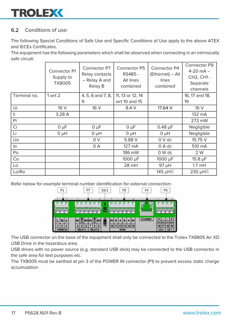
Conditions of use:
The following Special Conditions of Safe Use and Specific Conditions of Use apply to the above ATEX
and IECEx Certificates.
The equipment has the following parameters which shall be observed when connecting in an intrinsically
safe circuit:
Connector P1
Supply to
TX8005
Connector P7
Relay contacts
– Relay A and
Relay B
Connector P5
RS485 -
All lines
combined
Connector P4
(Ethernet) – All
lines
combined
Connector P9
4-20 mA –
CH2, CH1 -
Separate
channels
Terminal no. 1 wrt 2 4, 5, 6 and 7, 8,
9
11, 13 or 12, 14
wrt 10 and 15
16, 17 and 18,
19
Ui 16 V 16 V 8.4 V 17.64 V 16 V
Ii 3.28 A
132 mA
Pi
273 mW
Ci 0 µF 0 µF 0 µF 0.48 µF Negligible
Li 0 µH 0 µH 0 µH 0 µH Negligible
Uo
0 V 5.88 V 0 V dc 15.75 V
Io
0 A 127 mA 0 A dc 510 mA
Po
186 mW 0 W dc 2 W
Co
1000 µF 1000 µF 15.8 µF
Lo
28 mH 97 µH 1.7 mH
Lo/Ro
145 µH/μ 230 µH/μ
Refer below for example terminal number identification for external connection:
The USB connector on the base of the equipment shall only be connected to the Trolex TX8805 Air XD
USB Drive in the hazardous area.
USB drives with no power source (e.g. standard USB stick) may be connected to the USB connector in
the safe area for test purposes etc.
The TX8005 must be earthed at pin 3 of the POWER IN connector (P1) to prevent excess static charge
accumulation.

Air XD User Manual
www.trolex.com P5628.1601 Rev B 18
7. Technical information
Product Options
Product Specification
Particulate Sensing Parameters
PM size range PM1.0, PM2.5, PM4.25, PM10 and TSP TSP range Up to 40µm displayed in mg/m³ or µg/m³ Extended range TSP indicative up to 150µm displayed in mg/m³ or µg/m³ PM measurement range 0.35 - 40µm over 24 bins PM measurement capability* Up to 1500 mg/m³ PM continuous operating range** Up to 25 mg/m³ PM density 0.8 g/ml – 8.0 g/ml (default: 1.65 g/ml) PM measurement units mg/m³ or µg/m³ Averaging period 1s - 24hrs Averaging channels Two configurable (default: 15min and 8hr) Sampling interval 1s Particle count Up to 10,000 (particles/second) Flow rate Dynamic (1.2 L/min nominal)
Total flow rate 5.5 L/min (typical)
Accuracy +/- 5%
*The instrument can define particulate measurement peak trends up to the quantity specified. **During sustained high dust loading periods, the instrument will report on PM data up to the quantity specified. Note: Sustained exposure to PM quantities above 25 mg/m3 will be logged, however, may affect the operating life of the particulate sensor (OPC).
Air XD
Product options:
TX8005
Certification Power Supply Communications Particulate Monitoring
IECEx Group I (Aus) 06
19
9 V to 36 V dc 01 Ethernet
RS485
01
02
Full (all PM sizes)
TSP Only
01
02 ATEX/IECEx Group I 19

www.trolex.com 19 P5628.1601 Rev B
Technical Specification
Ambient temperature limits -10°C to +45°C Humidity 0-95% RH (non-condensing) Protection classification Main Enclosure, Dust and Waterproof: IP66
Particulate Flow Path, Cap Open: IP22 Particulate Flow Path, Cap Closed: IPX6
Housing material Polymer coated stainless steel Net weight 8.2 kg Cable entries 5 x M20 with removable blanks
1 x M20 breather gland (where specified) 1 x M20 USB connector (where specified)
Nominal power supply 12V, 500mA Minimum supply input 9.8V Max peak supply current 660mA nominal Power consumption 6W Inrush current 350mA Peak Relay outputs Two configurable (alarm outputs)
Dry contact Maximum rating 16V dc 300mA (internal overcurrent and overvoltage protection fitted)
4-20mA outputs Two configurable (real-time or average readings) R1 and R2 with adjustable set points Max attached load: 280μ
Communications RS485 data output with MODBUS RTU protocol, or
Ethernet (MODBUS TCP/IP optional)
Data download External USB interface
Instrument Data storage 8GB >10 years (logging interval dependent, default 10s) User interface 128 x 64 dot matrix display with RGB backlight
Navigation keypad (membrane) Visual alarms Display RGB backlight
Indicators 1 x Green high brightness LED – Sensor heartbeat 1 x Blue high brightness LED – Communications

Air XD User Manual
www.trolex.com P5628.1601 Rev B 20
Product Dimensions
Note: Recommended 100mm inlet clearance distance
305mm
30
5m
m
38
7m
m
156mm
Pa
ne
l Ke
y

www.trolex.com 21 P5628.1601 Rev B
8. Hardware Installation
Safety Precautions
Refer to Section 4 of this user manual before undertaking the installation of the Air XD instrument. The
installation location of the Air XD instrument is the prerogative of the installer and care should be taken
to ensure an appropriate position has been selected. Consider the location of a suitable power supply
and external fuses, access to a communications network and the protection of cabling from damage.
1. Secure the Air XD to a suitable mounting surface using the integrated mounting brackets.
2. Ensure that the Air XD is mounted in an upright position.
3. Unlock and open the enclosure door to access the internals of the enclosure.
4. Ensure power is isolated before making electrical connections to the instrument.
5. Power supply v must match the instrument IS Entity Parameters (refer to section 6.1.2).
6. Ensure external switches or fuses are installed where applicable
7. Run the required cables through the cable glands provided in the bottom of the enclosure.
8. Wire the cables into the relevant terminals on the internal plate (refer to section 8.4).
9. Tighten the cable gland against the cable to ensure an IP seal.
10. Close and lock the door after use to maintain IP rating of the enclosure.
11. Ensure that the particulate entry and exit ports are not restricted or covered.
Note: When the door is open, the instrument is susceptible to ingress so care must be taken to ensure
the location is clean during installation.
Mounting Details
Note: Ensure the Air XD housing is mounted
vertically during installation. 4 x M10
Fixing
255mm
36
2m
m

Air XD User Manual
www.trolex.com P5628.1601 Rev B 22
Main Parts
1. Ingress cap 10. Input/Output terminals 2. Inlet flow On/Off label 11. Input/Output labels 3. Display 12. Particulate inlet aperture 4. Status L.E.D’s 13. Enclosure door 5. Door lock 14. Main enclosure 6. Navigation keypad 15. Rating Plate 7. Mounting brackets 16. Particulate outlet grille 8. PCB mounting plate 17. M20 cable glands 9. Particulate sensor housing 18. USB interface
1. 2.
3. 4. 5. 6.
7.
8.
9.
10. 11.
12.
13. 14.
15.
16.
17.
18.

www.trolex.com 23 P5628.1601 Rev B
Electrical Connections
The figure and tables below detail the connections available internally in the Air XD instrument. The
connections can be accessed by opening the front housing of the instrument using the supplied key.
The connections are clearly labelled on the internal metal plate. Wires are inserted into the connector
terminals by first using a small flat-head screwdriver or dedicated tool inserted into the small recess
above the appropriate terminal. Pushing the screwdriver down into the mechanism opens the connector
terminal allowing the wire to be inserted into the opening. Before placing the wire into the connector,
ensure that the wire has been stripped back sufficiently and crimp attached, where required, to enable
a good electrical connection. Once the wire has been sufficiently pushed into the terminal, remove the
screwdriver to allow the mechanism to clamp the bare wire or crimped end. Give a gentle tug on the
wire to make sure it has been clamped sufficiently by the connector. Ensure mains cables are fixed in
place using the mounting points provided. Details of the connections are given in Tables 1 and 2 below.
Power In Relay Connections RS485 Communication
1 Supply voltage 4 Relay A: Normally Closed 10 RS485 0V 2 0V return 5 Relay A: Common 11 RS485 B 3 Earth 6 Relay A: Normally Open 12 RS485 A 7 Relay B: Normally Closed 13 RS485 B
8 Relay B: Common 14 RS485 A 9 Relay B: Normally Open 15 RS485 0V
Table 1: Power, Relay and RS485 terminal connections
DC Power Input

Air XD User Manual
www.trolex.com P5628.1601 Rev B 24
The pin connections listed in Table 2 for the Ethernet connector are not labelled in the figure but relate
to the internal connections of the RJ45 connector with Pin 1 on the left up to Pin 8 on the right. The
switches shown either side of the RS485 terminals in the figure allow setting of half duplex or full duplex
mode.
Ethernet 4 to 20mA – Ch2 and Ch1
Pin 1: TX+ 16 + out Pin 2: TX- 17 0V return Pin 3: RX+ 18 0V return Pin 4: No connection 19 + out Pin 5: No connection Pin 6: RX- Pin 7: No connection Pin 8: No connection
Table 2: Ethernet and 4 to 20mA connections
I/O Terminals
Power, RS485, 4-20mA and relay connection terminal data is highlighted below.
Actuation type Operating tool Solid/Stranded conductor 0.08 - 2.5mm² / 28 - 12 AWG Conductor with Ferrule 0.25 - 1.5mm² Strip length 5 - 6mm / 0.2 - 0.24 inch
Power Connections
For instruments connected to a DC power supply, it is the responsibility of the installer to ensure that
the instrument is installed with a DC supply, meeting re-enforced insulation requirements of EN61010-1
or equivalent.

www.trolex.com 25 P5628.1601 Rev B
RS485 – Output Signals
The Air XD provides in and out RS485 terminals to allow daisy chaining of multiple MODBUS devices.
For example: Pin 11 is common with Pin 13.
RS485 – Line Terminations
Some network installations may require a line termination resistor to be connected across RS485 lines
A and B. A 12OR resistor is available with SW4 set to off as standard, highlighted below.
Air XD User Manual
www.trolex.com P5628.1601 Rev B 26
9. Commissioning Once installed and powered for first time use, the Air XD requires some initial parameter set-up via the
on-screen user interface. On connection to the communications network, the instrument will be
selectable within the Air XD application software and will begin to push data to the PC application.
First Power On
Prior to commissioning and first use, the instrument should be inspected for any visible damages and
integrity of the enclosure.
1. Ensure that the electrical connections are correctly installed, as describe in section 8.4, and the Air
XD is connected to a communications network if required.
2. Ensure that the door is closed and secured.
3. Apply power to the Air XD.
4. A splash screen will be displayed for several seconds whilst the instrument configures.
5. Once configuration is complete, the Air XD will automatically display Live data for all PM sizes.
Application Software
The Air X application software is available for download and installation from Trolex LTD or via an
authorised distribution partner and is specifically designed for the capture of data sets collected by the
Air XD instrument. Installation and commissioning of the Air X application software is covered in the
separate Air X user manual and installation guide.
Note: The Air X application software is not required for general Air XD operation.

www.trolex.com 27 P5628.1601 Rev B
10. Controls and Indicators Navigation
The Air XD information software is navigated using the on-device keypad and display. The keypad
consists of four directional keys and a central enter key to allow the scrolling, selection and input of data
into the instrument.
Throughout the text in this document the navigation keys will be represented as follows:
Up – Up navigation key
Down – Down navigation key
Left – Left navigation key
Right – Right navigation key
Enter – Enter key
Directional Keypad User Interface
Air XD User Manual
www.trolex.com P5628.1601 Rev B 28
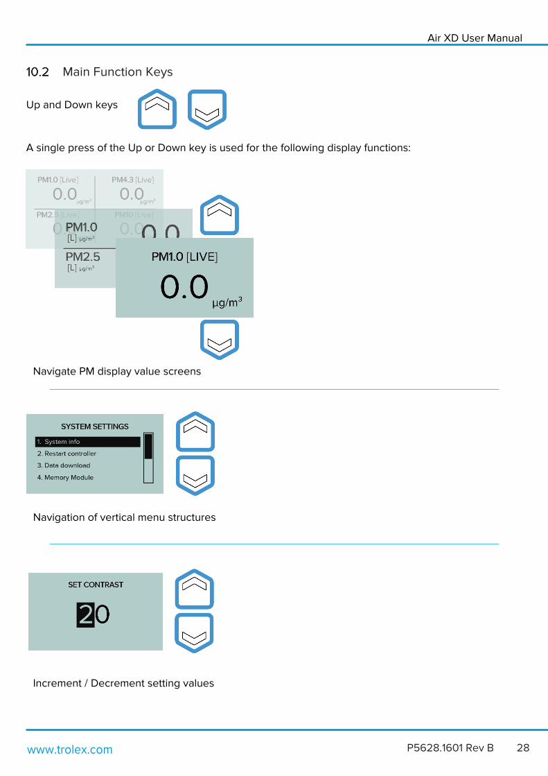
Main Function Keys
Up and Down keys
A single press of the Up or Down key is used for the following display functions:
Navigation of vertical menu structures
Navigate PM display value screens
Increment / Decrement setting values
www.trolex.com 29 P5628.1601 Rev B
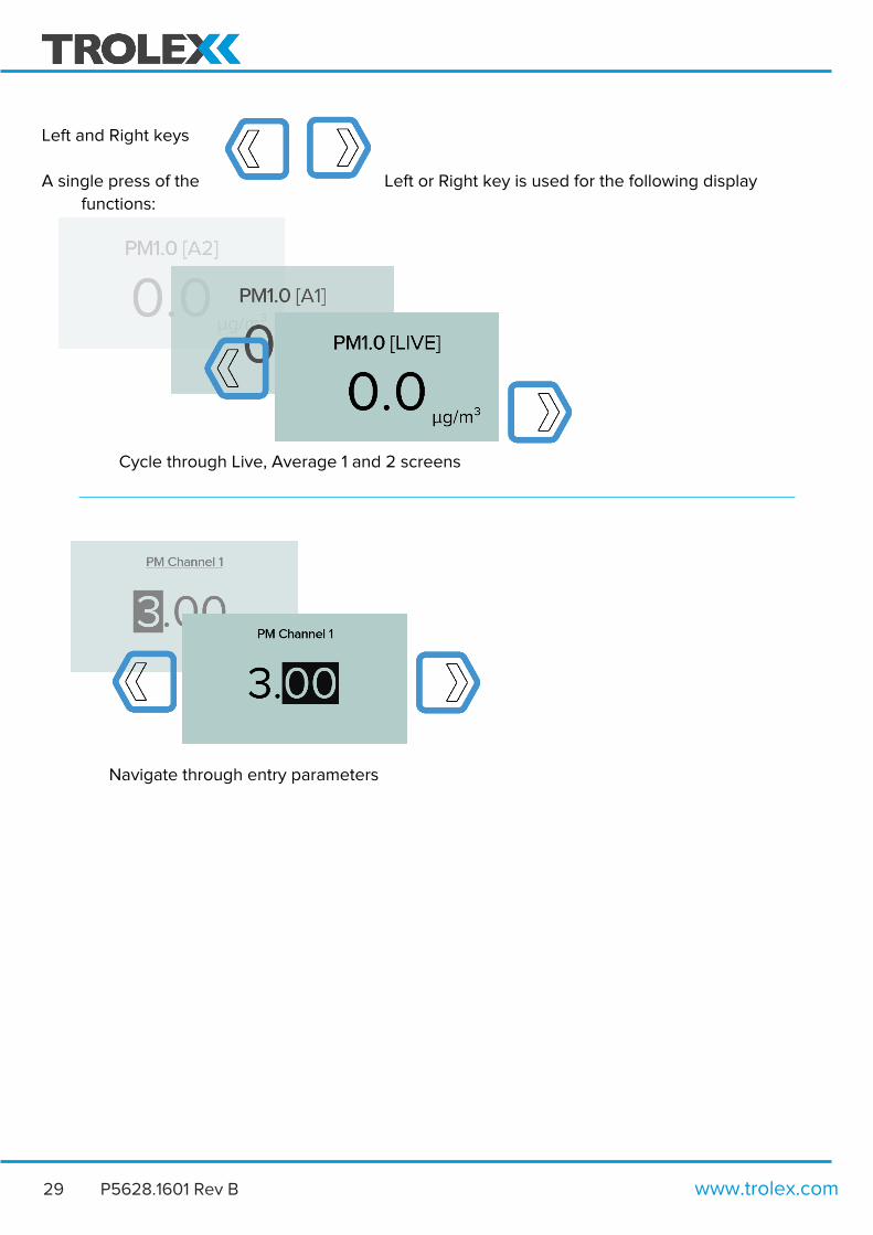
Left and Right keys
A single press of the Left or Right key is used for the following display
functions:
Navigate through entry parameters
Cycle through Live, Average 1 and 2 screens
Air XD User Manual
www.trolex.com P5628.1601 Rev B 30
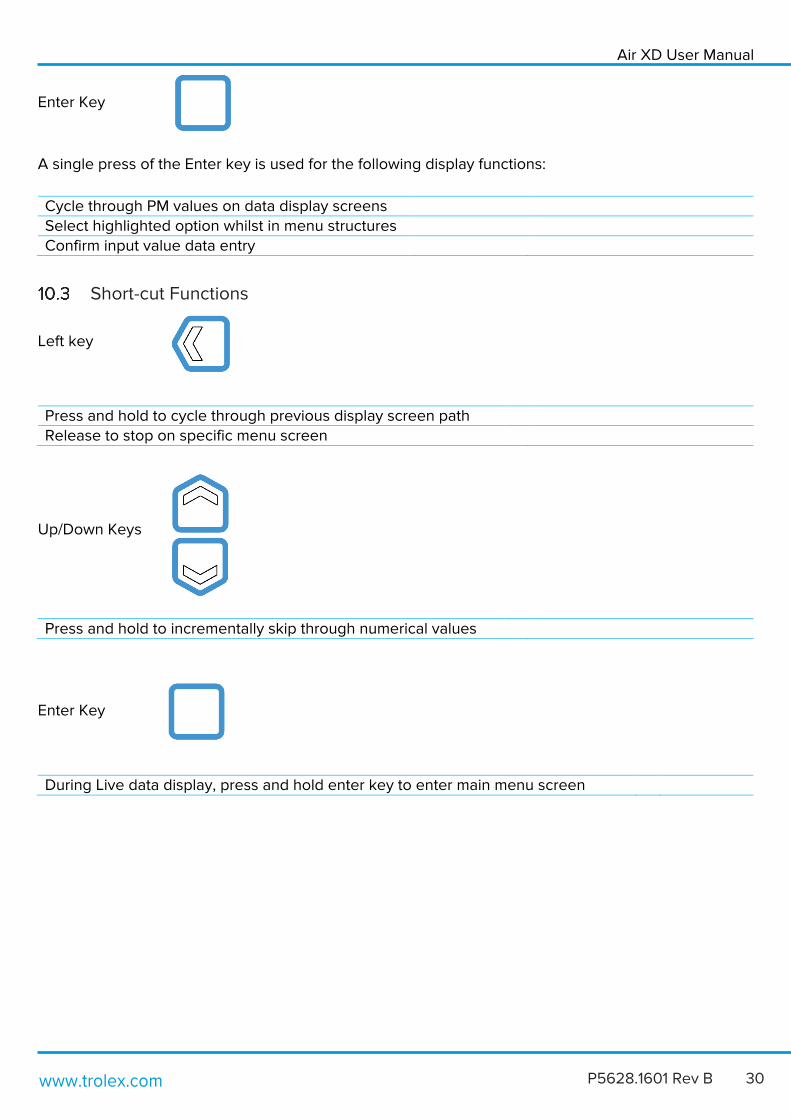
Enter Key
A single press of the Enter key is used for the following display functions:
Cycle through PM values on data display screens Select highlighted option whilst in menu structures Confirm input value data entry
Short-cut Functions
Left key
Press and hold to cycle through previous display screen path Release to stop on specific menu screen
Up/Down Keys
Enter Key
During Live data display, press and hold enter key to enter main menu screen
Press and hold to incrementally skip through numerical values

www.trolex.com 31 P5628.1601 Rev B
11. General Operation User Interface Display
On initial power up of the Air XD, particulate sampling will automatically start, and the graphical display
will show the following screens. Once the instrument has been configured, with custom values assigned
where required, user inputs will be saved in the instrument memory and on consecutive power cycles
the Air XD instrument will always display the following start up screens.
Air XD Power On > Title Card > Live Data Screen (Default to all PM value display)
Users can change the particulate sampling display information or enter the instrument settings menu by
following the steps outlined in section 11.2 PM value display map and 11.3 settings structure.
Title Screen
All PM Values [LIVE]
(Default landing screen)

Air XD User Manual
www.trolex.com P5628.1601 Rev B 32
PM Value Display Map The following map details the navigation through the Air XD PM value display screens. Users can select
between the number of PM data channels displayed on screen, 1, 2, 4 or all, alongside the required data
channel average (Live, Average 1 or Average 2).
Title Screen
All Channel Values
(Default landing screen)
Dual Channel Values
Single Channel Values
List Channel Values
Press ENTER to scroll
Press ENTER to scroll

www.trolex.com 33 P5628.1601 Rev B
Settings Structure The following settings can be configured within the Air XD settings menu by selecting the required field when highlighted within the black selection bar.
Each settings menu allows users to access the following information or selection options.
• PM Settings Configure and select custom PM values/ranges and map against instrument channels.
• Averaging Configure and select averaging periods for PM Values.
• Alarms Configure and select on-device alarm functionality.
• Communications Configure and select instrument communications protocols.
• Display Configure the on-device display and graphical interface.
• Date & Time Configure the instrument date and time settings.
• System Review, configure and update the instrument system settings.
Press ENTER to select from list
Settings Menu

Air XD User Manual
www.trolex.com P5628.1601 Rev B 34
PM Settings Configure and map PM sizes against selected channels (Ch1 to Ch4). PM values can be set to range from
1.00µm to 10.0µm. Users can choose to display either mg/m3 or 𝜇g/m3 for all available channels.
Note: The instrument logs data in 𝜇g/m3.
Setting custom PM values The following map details the navigation through the Air XD user interface screens to set and configure custom PM values against channels 1 to 4, including TSP. Settings > PM Settings > Select Channel for configuration
Settings
> PM Settings > Edit PM Value > Set PM Value
PM Channel Settings
Set PM Value
Press ENTER to set
Press to cycle through values
Press ENTER to set

www.trolex.com 35 P5628.1601 Rev B
PM Density
Allows the user to set a custom PM Density value for known particulates in the installation environment.
Note: The Air XD uses a PM density value to calculate the mass of known particulates in the installation
environment (1.65 g/ml as default).
Averaging Settings
Allows the user to set 2 separate averaging periods or time bases for all PM channels, including TSP.
Allowed range from 1min – 24hrs.
Settings > Averaging Time
>
Edit Averaging
Time
Settings > PM Density > Set PM Density
Air XD User Manual
www.trolex.com P5628.1601 Rev B 36
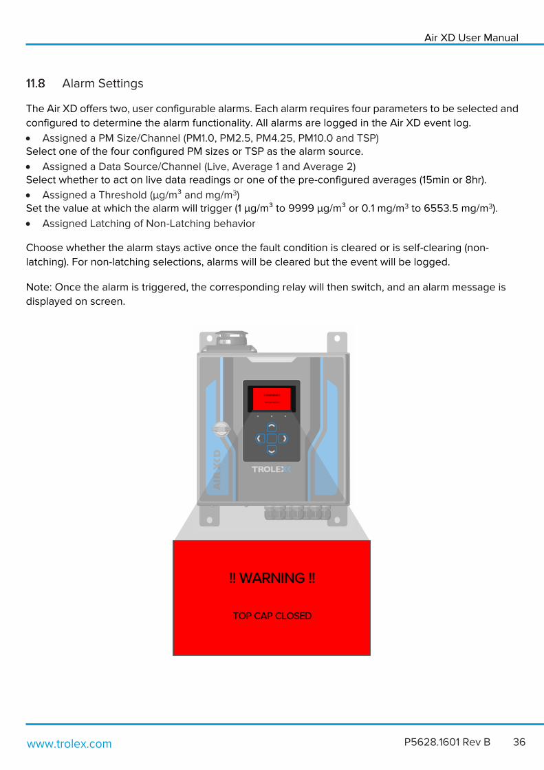
Alarm Settings
The Air XD offers two, user configurable alarms. Each alarm requires four parameters to be selected and
configured to determine the alarm functionality. All alarms are logged in the Air XD event log.
• Assigned a PM Size/Channel (PM1.0, PM2.5, PM4.25, PM10.0 and TSP) Select one of the four configured PM sizes or TSP as the alarm source.
• Assigned a Data Source/Channel (Live, Average 1 and Average 2) Select whether to act on live data readings or one of the pre-configured averages (15min or 8hr).
• Assigned a Threshold (µg/m³ and mg/m3) Set the value at which the alarm will trigger (1 µg/m³ to 9999 µg/m³ or 0.1 mg/m3 to 6553.5 mg/m3).
• Assigned Latching of Non-Latching behavior
Choose whether the alarm stays active once the fault condition is cleared or is self-clearing (non-
latching). For non-latching selections, alarms will be cleared but the event will be logged.
Note: Once the alarm is triggered, the corresponding relay will then switch, and an alarm message is
displayed on screen.

www.trolex.com 37 P5628.1601 Rev B
Channel Select
The Air XD has two alarm channels that can be assigned one of four particulate sizes or TSP (total suspended
particulate). Note: The current applied value is highlighted by the ‘selection tick’.
Threshold Channel
Select and assign an alarm to a specified data source. Note: The current applied value is highlighted by the
‘selection tick’.
Settings > Alarm Settings 1 > Alarm Settings 2 > Channel Select
Settings > Alarm Settings 1 > Alarm Settings 2 > Threshold Select

Air XD User Manual
www.trolex.com P5628.1601 Rev B 38
Set Alarm Threshold
Set the threshold value for when the alarm is activated. Threshold values can be configured between
1µg/m³ to 9999 µg/m³ or 0.1 mg/m3 to 6553.5 mg/m3.
Alarm Latching
Configure the latching behaviour for selected alarm. Note: The current applied value is highlighted by
the ‘selection tick’.
Alarm Settings 1 > Alarm Settings 2 > Alarm Threshold > Set Alarm Threshold
Alarm Settings 1 > Alarm Settings 2 > Set Alarm Latching

www.trolex.com 39 P5628.1601 Rev B
Alarm Enable/Disable
Enable or Disable audio visual alarms for selected alarm. Note: The current applied value is highlighted
by the ‘selection tick’.
.
4-20mA Outputs
The Air XD offers two 4-20mA outputs. Each 4-20mA output requires two parameters to be selected
and configured to determine the functionality of each analogue output.
• Assigned a PM Size/Channel (PM1.0, PM2.5, PM4.25, PM10.0 and TSP) Select one of the four configured PM sizes or TSP as the alarm source.
• Assigned a data channel (Live, Average 1 or Average 2) Select one of the three data sets to assign the selected 4-20mA output to.
• Assigned the full-scale range of the channel For example: a full-scale range of 2000µg/m³ will output 20mA for a value greater or equal to 2000
µg/m³ and for a value of 0 µg/m³ the channel will always output 4mA.
A full-scale range of 6553.5 mg/m³ will output 20mA for a value greater or equal to 6553.5 mg/m³ and
for a value of 0 mg/m³ the channel will always output 4mA.
• Enable/Disable the channel A disabled channel with output 0mA.
During instrument start up and initialisation, each 4-20mA output will perform a calibration routine which
involves sweeping the output from 0-20mA before returning to 4mA. After this has been completed, the
output will return to configured functionality.
Alarm Settings 1 > Alarm Settings 2 > Set Alarm EN/DIS

Air XD User Manual
www.trolex.com P5628.1601 Rev B 40
Select PM Channel
The Air XD has two 4-20mA outputs that can be assigned one of four particulate sizes or TSP (Total Suspended
Particulate). Note: The current applied value is highlighted by the ‘selection tick’.
Map 4-20mA to Data Channel
Map the selected 4-20mA output to the required data channel (Live, Average 1 or Average 2).
Set Max PM Value
Set the 4-20mA scaling range for each 4-20mA output. (0-9999 µg/m3 or 0.1 mg/m3 to 6553.5 mg/m3).
Settings > 4-20mA Outputs > 4-20mA Channel > Map 4-20mA
4-20mA Outputs > 4-20mA Channel > 4-20mA Max PM > Set Max PM
Settings > 4-20mA Outputs > 4-20mA Channel > Map 4-20mA

www.trolex.com 41 P5628.1601 Rev B
Enable/Disable
Enable or Disable 4-20mA outputs. Note: The current applied value is highlighted by the ‘selection tick’.
Status
Check the overview status of the 4-20mA channels.
4-20mA Outputs > 4-20mA Channel > Set En/Dis >
4-20mA Outputs > 4-20mA Status >

Air XD User Manual
www.trolex.com P5628.1601 Rev B 42
Communications
The Air XD offers two selectable communications protocols, RS485 MODBUS and Ethernet MODBUS
TCP/IP, that can be used to configure and network the instrument. Each communication protocol
requires the network and connection parameters to be correctly configured on the instrument and
network where applicable.
Ethernet Communications
The Air XD supports communications over Ethernet MODBUS TCP/IP and can be configured per the
system menus below. Ethernet communications require the following parameters to be selected and
configured to establish the successful communication with the designated server. Ethernet
communication requires a DNS Server as standard and if selecting ‘dynamic’ (DHCP) IP address, will
require a DHCP Server. Firewall settings must allow outgoing traffic on selected port numbers.
Note: The MODBUS TCP/IP communicates over ‘Port 502’.
Network Status
Check the overview status of the connected network.
IP Settings
The Air XD IP settings can be configured based on application requirements. From the IP settings menu
users can select and configure the following.
Settings > Communications > Ethernet
Ethernet > Network Status > Status
Ethernet > IP Settings > Settings
www.trolex.com 43 P5628.1601 Rev B
• Assignment Type Select a ‘static’ or ‘dynamic’ (DHCP) IP address.
• Static IP Address Enter and set static IP address.
• Subnet Mask Address Enter and set subnet mask address.
• Gateway Address Enter and set gateway address.
• Primary DNS Enter and set primary DNS address.
• Secondary DNS Enter and set secondary DNS address.
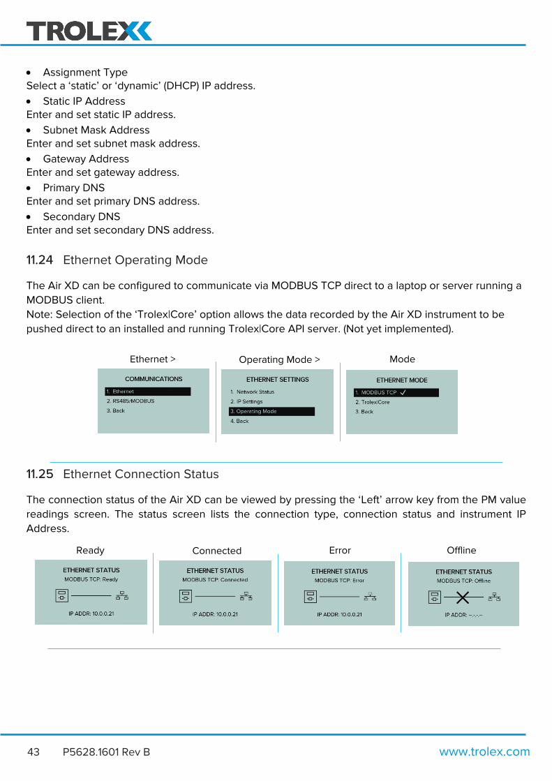
Ethernet Operating Mode
The Air XD can be configured to communicate via MODBUS TCP direct to a laptop or server running a
MODBUS client.
Note: Selection of the ‘Trolex|Core’ option allows the data recorded by the Air XD instrument to be
pushed direct to an installed and running Trolex|Core API server. (Not yet implemented).
Ethernet Connection Status
The connection status of the Air XD can be viewed by pressing the ‘Left’ arrow key from the PM value
readings screen. The status screen lists the connection type, connection status and instrument IP
Address.
Ethernet > Operating Mode > Mode
Ready Connected Error Offline

Air XD User Manual
www.trolex.com P5628.1601 Rev B 44
RS485 MODBUS Communications
The Air XD has configurable MODBUS baud rates and a user configurable address. It is possible to
configure the MODBUS device address and baud rate through the on-device display menu.
Settings > Communications > RS485/MODBUS
Set Baud Rate
The Air XD instrument baud rate can be selected and assigned from a pre-configured list of options.
Note: The current applied value is highlighted by the ‘selection tick’.
• 4800
• 9600
• 14400
• 19200
• 38400
• 57600
• 115200 (Default)
Set Device Address
The Air XD instrument address is user selectable and can be configured between 001-255.
Communications > RS485 MODBUS > MODBUS Address
>
Set Device Address
Settings > RS485 MODBUS > Set Baud Rate Communications >

www.trolex.com 45 P5628.1601 Rev B
Display
The Air XD has a 128 x 64 dot matrix display with backlight. Users can select and configure display
contrast, backlight colour and brightness. It is also possible to set power saving mode with display sleep
functionality.
Adjusting Display Contrast
The Air XD display can be adjusted to align the contrast ratios with the installation environment.
Set Display Backlight
The Air XD display can be adjusted to align the backlight brightness with the installation environment.
Settings > Display > Adjust Contrast > Set Contrast
Settings > Display > Adjust Backlight > Set Backlight

Air XD User Manual
www.trolex.com P5628.1601 Rev B 46
Set Display Colour
The Air XD display can be adjusted to configure the on-screen colour profile.
Set Display Sleep
The Air XD display can be set to enter sleep mode to allow for power saving where required.
The Air XD display can also be configured to sleep after a chosen time period.
Settings > Display > Set Colour >
Settings > Display > Display Sleep > Enable/Disable
Display > Display Sleep > Enter Sleep Time > Set Sleep Time
www.trolex.com 47 P5628.1601 Rev B
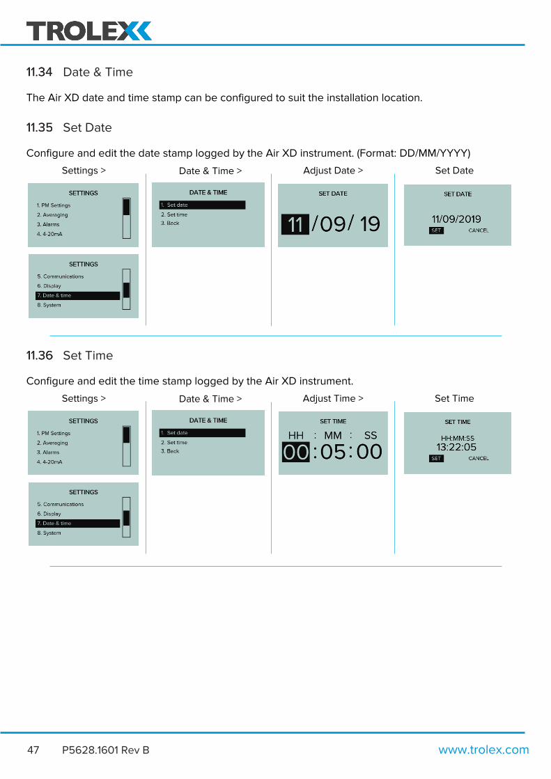
Date & Time
The Air XD date and time stamp can be configured to suit the installation location.
Set Date
Configure and edit the date stamp logged by the Air XD instrument. (Format: DD/MM/YYYY)
Set Time
Configure and edit the time stamp logged by the Air XD instrument.
Settings > Date & Time > Adjust Date > Set Date
Settings > Date & Time > Adjust Time > Set Time

Air XD User Manual
www.trolex.com P5628.1601 Rev B 48
System
The Air XD system menu allows users to access system performance, serial information, update firmware
and restart the instrument.
System Information
The system information menu allows users to view the functional status of the Air XD instrument.
Restart Controller
The Air XD instrument can be forced to restart and reboot through the ‘Restart Controller’ menu.
Settings > System Settings > System Info
Settings > Restart Controller > Confirm Reboot > Rebooting
www.trolex.com 49 P5628.1601 Rev B
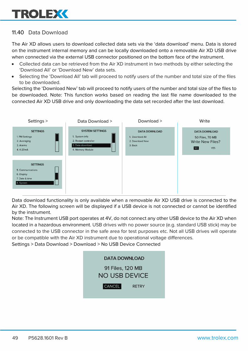
Data Download
The Air XD allows users to download collected data sets via the ‘data download’ menu. Data is stored
on the instrument internal memory and can be locally downloaded onto a removable Air XD USB drive
when connected via the external USB connector positioned on the bottom face of the instrument.
• Collected data can be retrieved from the Air XD instrument in two methods by either selecting the ‘Download All’ or ‘Download New’ data sets.
• Selecting the ‘Download All’ tab will proceed to notify users of the number and total size of the files to be downloaded.
Selecting the ‘Download New’ tab will proceed to notify users of the number and total size of the files to
be downloaded. Note: This function works based on reading the last file name downloaded to the
connected Air XD USB drive and only downloading the data set recorded after the last download.
Data download functionality is only available when a removable Air XD USB drive is connected to the Air XD. The following screen will be displayed if a USB device is not connected or cannot be identified by the instrument. Note: The Instrument USB port operates at 4V, do not connect any other USB device to the Air XD when
located in a hazardous environment. USB drives with no power source (e.g. standard USB stick) may be
connected to the USB connector in the safe area for test purposes etc. Not all USB drives will operate
or be compatible with the Air XD instrument due to operational voltage differences.
Settings > Data Download > Download > No USB Device Connected
Settings > Data Download > Download > Write

Air XD User Manual
www.trolex.com P5628.1601 Rev B 50
Memory Module
The Air XD contains an internal Memory Module that is used to locally store collected data sets on the
instrument. The module can be configured from the settings menu to allow local data collection to take
place or to stop the Air XD from writing to the internal memory.
For the majority of applications, the internal Memory Module will be used and configured to allow the
Air XD instrument to locally store data as well as push data to the Air X software via selected
communications channels.
For applications that may require power saving functionality, the internal memory module can be de-
selected. Note: The current selection is highlighted by the ‘selection tick’.
The internal Memory Module contains 8GB of storage capacity, which depending on the frequency of
data collected and written may require clearing. To clear the data set stored on the instrument, follow
the on-screen functions detailed below.
Settings > Memory Module > Fit/No Fit > Select Fit/No Fit
Settings > Memory Module > Wipe Data > Delete All

www.trolex.com 51 P5628.1601 Rev B
Firmware Update
On notification of firmware update and release, the Air XD and internal Memory Module can be update
via the firmware update menu below. The instrument requires the update to take place via the
connection of the external Air XD USB drive loaded with the latest firmware.
Settings > Firmware Update > Select Device > Confirm Update
Air XD User Manual
www.trolex.com P5628.1601 Rev B 52
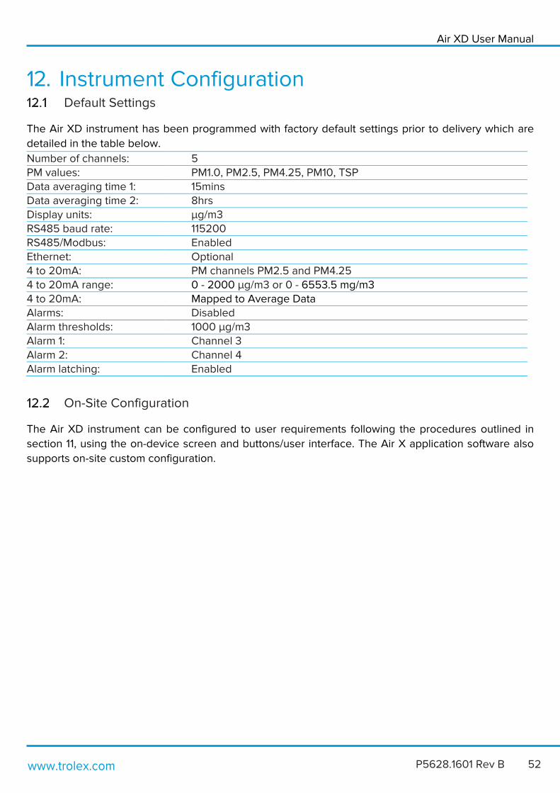
12. Instrument Configuration Default Settings
The Air XD instrument has been programmed with factory default settings prior to delivery which are
detailed in the table below.
Number of channels: 5 PM values: PM1.0, PM2.5, PM4.25, PM10, TSP Data averaging time 1: 15mins Data averaging time 2: 8hrs Display units: µg/m3 RS485 baud rate: 115200 RS485/Modbus: Enabled Ethernet: Optional 4 to 20mA: PM channels PM2.5 and PM4.25 4 to 20mA range: 0 - 2000 µg/m3 or 0 - 6553.5 mg/m3 4 to 20mA: Mapped to Average Data Alarms: Disabled Alarm thresholds: 1000 µg/m3 Alarm 1: Channel 3 Alarm 2: Channel 4 Alarm latching: Enabled
On-Site Configuration
The Air XD instrument can be configured to user requirements following the procedures outlined in
section 11, using the on-device screen and buttons/user interface. The Air X application software also
supports on-site custom configuration.

www.trolex.com 53 P5628.1601 Rev B
MODBUS Addresses
The Air XD contains the following three MODBUS registers:
Input Register (Function code 4)
This is a read-only register containing factory programmed instrument parameters, including serial
numbers, firmware versions and live data sets.
Register Description Data Type Units 0 Product TX number Uint16_t 1 Firmware Version (Major) Uint16_t 2 Firmware Version (Minor) Uint16_t 3 Firmware Version (Patch) Uint16_t 4 Serial Number (Characters 1 & 2) Char Ascii format 5 Serial Number (Characters 3 & 4) Char 6 Serial Number (Characters 5 & 6) Char 7 Serial Number (Characters 7 & 18) Char 8 Serial Number (Characters 9 & 10) Char 9 Bin 0 – 0.46𝜇m Uint16_t Counts
10 Bin 1 – 0.66𝜇m Uint16_t Counts
11 Bin 2 – 0.89𝜇m Uint16_t Counts
12 Bin 3 – 1.17𝜇m Uint16_t Counts
13 Bin 4 – 1.47𝜇m Uint16_t Counts
14 Bin 5 – 1.80𝜇m Uint16_t Counts
15 Bin 6 – 2.5𝜇m Uint16_t Counts
16 Bin 7 – 3.5𝜇m Uint16_t Counts
17 Bin 8 – 4.51𝜇m Uint16_t Counts
18 Bin 9 – 5.76𝜇m Uint16_t Counts
19 Bin 10 – 7.25𝜇m Uint16_t Counts
20 Bin 11 – 9𝜇m Uint16_t Counts
21 Bin 12 – 11𝜇m Uint16_t Counts
22 Bin 13 – 13𝜇m Uint16_t Counts
23 Bin 14 – 15.01𝜇m Uint16_t Counts
24 Bin 15 – 17.01𝜇m Uint16_t Counts
25 Bin 16 – 19.02𝜇m Uint16_t Counts
26 Bin 17 – 21.02𝜇m Uint16_t Counts
27 Bin 18 – 23.51𝜇m Uint16_t Counts
28 Bin 19 – 26.51𝜇m Uint16_t Counts
29 Bin 20 – 29.51𝜇m Uint16_t Counts
30 Bin 21 – 32.51𝜇m Uint16_t Counts
31 Bin 22 – 35.51𝜇m Uint16_t Counts
32 Bin 23 – 38.51𝜇m / 140𝜇m extended mode Uint16_t Counts
33 Sampling Period Uint16_t 0.01s/bit 34 Sample Flow Rate Uint16_t 0.01ml/s/bit 35 Sensor Temperature Uint16_t 0.01°C/bit 36 Sensor Humidity Uint16_t 0.01%/bit 37 PM A Size (Lower 16 bits) Float32_t µg/m^3 38 PM A Size (Upper 16 bits) Float32_t µg/m^3 39 PM B Size (Lower 16 bits) Float32_t µg/m^3

Air XD User Manual
www.trolex.com P5628.1601 Rev B 54
40 PM B Size (Upper 16 bits) Float32_t µg/m^3 41 PM C Size (Lower 16 bits) Float32_t µg/m^3 42 PM C Size (Upper 16 bits) Float32_t µg/m^3 43 PM D Size (Lower 16 bits) Float32_t µg/m^3 44 PM D Size (Upper 16 bits) Float32_t µg/m^3 45 Total Suspended Particulates (TSP) (Lower 16 bits) Float32_t µg/m^3 46 Total Suspended Particulates (TSP) (Upper 16 bits) Float32_t µg/m^3 47 PM A Average 1 (Lower 16 bits) 48 PM A Average 1 (Upper 16 bits) 49 PM B Average 1 (Lower 16 bits) 50 PM B Average 1 (Upper 16 bits) Float32_t µg/m^3 51 PM C Average 1 (Lower 16 bits) Float32_t µg/m^3 52 PM C Average 1 (Upper 16 bits) Float32_t µg/m^3 53 PM D Average 1 (Lower 16 bits) Float32_t µg/m^3 54 PM D Average 1 (Upper 16 bits) Float32_t µg/m^3 55 Total Suspended Particulates Average 1
(TSP) (Lower 16 bits) Float32_t µg/m^3
56 Total Suspended Particulates Average 1 (TSP) (Upper 16 bits)
Float32_t µg/m^3
57 PM A Average 2 (Lower 16 bits) Float32_t µg/m^3 58 PM A Average 2 (Upper 16 bits) Float32_t µg/m^3 59 PM B Average 2 (Lower 16 bits) Float32_t µg/m^3 60 PM B Average 2 (Upper 16 bits) Float32_t µg/m^3 61 PM C Average 2 (Lower 16 bits) Float32_t µg/m^3 62 PM C Average 2 (Upper 16 bits) Float32_t µg/m^3 63 PM D Average 2 (Lower 16 bits) Float32_t µg/m^3 64 PM D Average 2 (Upper 16 bits) Float32_t µg/m^3 65 Total Suspended Particulates Average 2
(TSP) (Lower 16 bits) Float32_t µg/m^3
66 Total Suspended Particulates Average 2 (TSP) (Upper 16 bits)
Float32_t µg/m^3
67 Air XD Supply Voltage Uint16_t mv/bit 68 Laser Current / mA Uint16_t mA/bit 69 Fan Current / mA Uint16_t mA/bit 70 Status Register Uint16_t

www.trolex.com 55 P5628.1601 Rev B
Coil Register
(Function code 1 read – Function code 5 write)
This is a read/write register containing the instrument binary settings, including alarm status, PM units
and 4-20mA output enable/disable status. Writing to this register will result in the setting being changed
permanently.
Note: However, if an alarm is activated, writing to the alarm status coil will dismiss the active alarm until
the alarm threshold parameters have been re-exceeded.
Register Description Data Type Units 0 Channel 1 alarm status Bool 1 Channel 2 alarm status Bool 2 Channel 1 alarm latch Bool (1=latch, 0 auto
reset) 3 Channel 2 alarm latch Bool (1=latch, 0 auto
reset) 4 Channel 1 alarm mute Bool 5 Channel 2 alarm mute Bool 6 PM Units Bool (0 =µg/m³,
1=mg/m³) 7 TSP Extended Range Bool (0=false, 1=true) 8 Memory Module Fitted Bool (0=Not fitted, 1=
1 fitted) 9 4-20mA Channel 1
Enable/Disable Bool 0 – Disabled
1 – Enabled 10 4-20mA Channel 2
Enable/Disable Bool 0 – Disabled
1 – Enabled
Air XD User Manual
www.trolex.com P5628.1601 Rev B 56
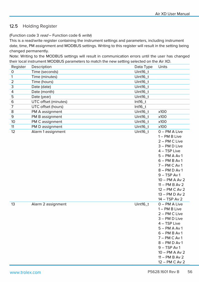
Holding Register
(Function code 3 read – Function code 6 write)
This is a read/write register containing the instrument settings and parameters, including instrument
date, time, PM assignment and MODBUS settings. Writing to this register will result in the setting being
changed permanently.
Note: Writing to the MODBUS settings will result in communication errors until the user has changed
their local instrument MODBUS parameters to match the new setting selected on the Air XD.
Register Description Data Type Units 0 Time (seconds) Uint16_t 1 Time (minutes) Uint16_t 2 Time (hours) Uint16_t 3 Date (date) Uint16_t 4 Date (month) Uint16_t 5 Date (year) Uint16_t 6 UTC offset (minutes) Int16_t 7 UTC offset (hours) Int16_t 8 PM A assignment Uint16_t x100 9 PM B assignment Uint16_t x100 10 PM C assignment Uint16_t x100 11 PM D assignment Uint16_t x100 12 Alarm 1 assignment Uint16_t 0 – PM A Live
1 – PM B Live 2 – PM C Live 3 – PM D Live 4 – TSP Live 5 – PM A Av 1 6 – PM B Av 1 7 – PM C Av 1 8 – PM D Av 1 9 – TSP Av 1 10 – PM A Av 2 11 – PM B Av 2 12 – PM C Av 2 13 – PM D Av 2 14 – TSP Av 2
13 Alarm 2 assignment Uint16_t 0 – PM A Live 1 – PM B Live 2 – PM C Live 3 – PM D Live 4 – TSP Live 5 – PM A Av 1 6 – PM B Av 1 7 – PM C Av 1 8 – PM D Av 1 9 – TSP Av 1 10 – PM A Av 2 11 – PM B Av 2 12 – PM C Av 2

www.trolex.com 57 P5628.1601 Rev B
13 – PM D Av 2 14 – TSP Av 2
14 Alarm 1 threshold Uint16_t (As µg/m³) 15 Alarm 2 threshold Uint16_t (As µg/m³) 16 4-20mA Ch 1 assignment Uint16_t (0 = PM A
3 = PM D) 17 4-20mA Ch 2 assignment Uint16_t (0 = PM A
3 = PM D) 18 4-20mA Ch 1 scaling Uint16_t 19 4-20mA Ch 2 scaling Uint16_t 20 Average Ch 1 time Uint16_t (As minutes) 21 Average Ch 2 time Uint16_t (As minutes) 22 MODBUS baud rate Uint16_t 0 = 4800
1 = 9600 2 = 14400 3 = 19200 4 = 38400 5 = 57600 6 = 115200
23 MODBUS Address Uint8_t
Instrument Self-Test
On initial power on, the Air XD is programmed to perform a set of initialisation tests which are listed
and described below. Throughout general function, the Air XD will periodically perform these tests to
ensure correct operation.
• OPC sensor comms check Ensures communications and correct functionality of the OPC sensor.
• OPC temp sensor test Ensures the OPC sensor is operating within the specified safe temperature limits.
• 4-20mA self-test During instrument start up and initialisation, each 4-20mA output will perform a calibration routine which
involves sweeping the output from 0-20mA before returning to 4mA. After this has been completed, the
output will return to configured functionality.
• Data logging comms test Ensures communications and correct functionality of the Air XD memory module.
• EEPROM memory test Ensures communications and functionality of the EEPROM is correct and that custom defined user
settings are not lost.

Air XD User Manual
www.trolex.com P5628.1601 Rev B 58
13. Maintenance The maintenance of the Air XD must only be carried out by competent personnel. Maintenance shall be
considered with reference to the local safety regulations and authorities.
Visual Checks
Periodic visual checks should be carried out to assess if there are any issues arising with the Air XD
instrument. Check for:
1. External damage to the instrument. Plastic parts should not be cracked or broken which could affect
the IP rating of the instrument.
2. Internal or external damage to wiring that is connected to the Air XD instrument.
3. Labels on the instrument are still in place and are not peeling or discolouring. Ensure all labels are
clean by following 13.2 below.
Cleaning Labels
It is recommended to periodically clean the instrument with a damp cloth, to ensure the instrument
display and keypad is clean and legible.
Particulate Entry/Exit apertures
The Air XD has been designed to allow for infrequent pressure washing during maintenance schedules.
Note: Ensure inlet cap is closed before pressure washing the Air XD instrument.
It is important that an appropriate distance is kept between a pressure washer and all Air XD surfaces
when cleaning to avoid any damage to the surface being cleaned. Care should also be taken to ensure
that the underside of the instrument is not subject to the direct water jet to ensure that water does not
enter the particulate flow path.
The particulate exit aperture is protected by a stainless-steel grille to minimise the ingress of flora and
fauna into the Air XD instrument. It is recommended that the grille it is checked and cleaned during
maintenance periods to ensure that it has not become clogged with ingress that may obscure the
particulate sensing airflow.

www.trolex.com 59 P5628.1601 Rev B
14. Troubleshooting The following sections detail and contain information to assist with the troubleshooting of instrument
functionality if required. If an issue is non-resolvable based on the information below, please contact the
Trolex product support team.
High Temperature operating
The Air XD operates a protective thermal cut-out sequence when the temperature inside the instrument
exceeds the maximum operating temperature specification, detailed in section 7. This protective
measure is in place to maintain the lifespan and operating functionality of the optical sensor assembly
when the Air XD is installed in environments with high ambient temperatures.
Note: The operating lifespan and performance of the optical sensor assembly may be reduced when the
Air XD is operational at maximum temperature limits for extended periods of time.
Low Temperature Start-up
If the internal temperature of the instrument is suspected to be below -10oC, for example if it has been
left powered off for a period of time in a very cold environment, damage to the optical assembly may
occur when power is applied. Allow the instrument to reach safe operating temperature before applying
power.

Air XD User Manual
www.trolex.com P5628.1601 Rev B 60
Fault Codes
The following codes relate to on-screen warnings that the Air XD will display when a fault is
encountered during normal operations.
Code Fault Name Fault Description Fault Check 0x0009 Failed to Load Settings Failed to load and apply user
configured settings. As standard the Air XD default settings will be applied.
Re-apply custom settings and check if unit saves and restores files. Contact Trolex or approved distributor if this fails.
0x0301 No Sensor Comms Communications with the particulate sensor assembly has been lost.
Check ‘D’ type connector to sensor housing and power cycle unit.
0x0304 Fan Current Too High Particulate sampling fan may have malfunctioned.
Check instrument is operating within rated temperature range.
0x0305 No Fan Current Particulate sampling fan may have malfunctioned.
Check instrument is operating within rated temperature range.
0x0306 Sensor Laser Current High
Particulate sensor may have failed or operating at excessive temperatures.
Check instrument is operating within rated temperature range.
0x0307 Sensor Laser Current Low
Particulate sensor may have failed.
Contact Trolex or approved distributor.
0x0308 Sensor Temp Too High Instrument is operating above specified temperature limits. Unit has gone into safe mode.
Reduce operating temperature below 50°C
0x0402 Lost Memory Module Comms
Communications to memory module has failed. Data logging functionality is lost.
Power cycle to reset instrument processor and retry. Contact Trolex or approved distributor if this fails.

www.trolex.com 61 P5628.1601 Rev B
15. Glossary and Definitions
Flow rate The volume of fluid which passes per unit time
IP Ingress Protection
𝝁g/m3 Microgram per meter cubed. The concentration of an air pollutant given in micrograms (one-millionth of a gram) per cubic meter of air
mg/m3 Milligram per meter cubed. The concentration of an air pollutant given in milligrams (one-thousandth of a gram) per cubic meter of air
OPC Optical particulate counter
PPM Parts per million
Particulate Matter (PM) General term for a mixture of solids and liquid droplets suspended in the air from typical processes including combustion, industrial activities or natural sources.
PMx PMx is particulate matter X micrometer or less in diameter.
TSP Total Suspended Particulate matter in the air measuring up to 40 micrometers for standard TSP range and up to 150 micrometers for extended TSP range.
16. Disposal Waste of Electrical and Electronic Equipment (WEEE) Directive (2012/19/EU)
This symbol, if marked on the product or its packaging, indicates that
this product must not be disposed of with general household waste.
In the European Union and many other countries, separate collection
systems have been set up to handle the recycling of electrical and
electronic waste.
At the end of the product’s life, do not dispose of any electronic sensor, component or instrument in the
domestic waste. Contact Trolex or the distributor for disposal instructions.
17. Technical Support Our UK technical services team are available to provide expert ongoing technical assistance and
technical support packages tailored to your specific requirements.
Please contact our technical services team:
Tel: +44 (0)161 483 1435
Email: [email protected]

Air XD User Manual
www.trolex.com P5628.1601 Rev B 62
18. Disclaimers The information provided in this document contains general descriptions and technical characteristics
of the performance of the product. It is not intended as a substitute for and is not to be used for
determining suitability or reliability of this product for specific user applications. It is the duty of any
user or installer to perform the appropriate and complete risk assessment, evaluation and testing of
the products with respect to the specific application or use. Trolex shall not be responsible or liable for
misuse of the information contained herein. When instruments are used for applications with technical
safety requirements, the relevant instructions must be followed.
All pertinent state, regional, and local safety regulations must be observed when installing and using
this instrument. For reasons of safety and to help ensure compliance with documented system data,
only Trolex or its affiliates should perform repairs to components.
Trolex Ltd. reserves the right to revise and update this documentation from time to time without
obligation to provide notification of such revision or change. Revised documentation may be
obtainable from Trolex.
Trolex Ltd. reserves the right, without notice, to make changes in equipment design or performance as
progress in engineering, manufacturing or technology may warrant.
19. Revisions
Description ECR Date Initials Initial Draft Release - 12/11/2019 KH Revision A Release - 26/11/2019 KH Revision B Release – Certification Updates 5003 24/01/2020 KH

www.trolex.com 63 P5628.1601 Rev B
20. Feedback If you have any suggestions for improvements or amendments, or find errors in this publication, please
notify us at [email protected].
21. Trademarks © 2019 Trolex® Limited.
No part of this document may be reproduced in any form or by any means, electronic or mechanical,
including photocopying, without express written permission of Trolex.
Trolex is a registered trademark of Trolex Limited. The use of all trademarks in this document is
acknowledged.
Trolex Ltd, Newby Road, Hazel Grove, Stockport, Cheshire, SK7 5DY, UK
+44 (0) 161 483 1435 [email protected]

Air XD User Manual
www.trolex.com P5628.1601 Rev B 64
Trolex Ltd. Newby Road, Hazel Grove, Stockport, Cheshire SK7 5DY, UK
t: +44 (0)161 483 1435 e: [email protected] www.trolex.com