type 24a07 37-4709d en - climate.emerson.com · r fig. 4. schéma de câblage pour un thermosta t...
TRANSCRIPT
Type 24A07 “Slimline” level-Temp
SilenT operATor (normally open)
inSTAllATion inSTrucTionS
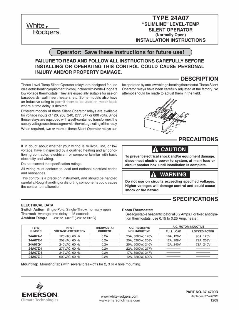
DeScripTionThese Level-Temp Silent Operator relays are designed for use on electric heating equipment in conjunction with White-Rodgers low voltage thermostats. They are especially suitable for use on baseboards, wall insert heaters, etc. Some models also have an inductive rating to permit them to be used on motor loads where a time delay is desired.Different models of these Silent Operator relays are available for voltage inputs of 120, 208, 240, 277, 347 or 600 volts. Since these relays are equipped with a self-contained transformer, the supply voltage used must agree with the voltage rating of the relay.When required, two or more of these Silent Operator relays can
operator: Save these instructions for future use!
FAilure To reAD AnD FolloW All inSTrucTionS cAreFully BeFore inSTAllinG or operATinG THiS conTrol coulD cAuSe perSonAl inJury AnD/or properTy DAmAGe.
be operated by one low voltage heating thermostat. These Silent Operator relays have been carefully adjusted at the factory. No attempt should be made to adjust them in the field.
If in doubt about whether your wiring is millivolt, line, or low voltage, have it inspected by a qualified heating and air condi-tioning contractor, electrician, or someone familiar with basic electricity and wiring.Do not exceed the specification ratings.All wiring must conform to local and national electrical codes and ordinances.This control is a precision instrument, and should be handled carefully. Rough handling or distorting components could cause the control to malfunction.
WARNING!Do not use on circuits exceeding specified voltages. Higher voltages will damage control and could cause shock or fire hazard.
CAUTION!To prevent electrical shock and/or equipment damage, disconnect electric power to system, at main fuse or circuit breaker box, until installation is complete.
SpeciFicATionSelecTricAl DATASwitch Action: Single-Pole, Single-Throw, normally openThermal: Average time delay – 45 secondsAmbient Temp.: -20° to 140°F (-24° to 60°C)
room Thermostat:Set adjustable heat anticipator at 0.2 Amps. For fixed anticipa-tion thermostats, use 0.15 to 0.25 Amp. heater.
TypenumBer
inpuTvolTAGe /Frequency
THermoSTATcurrenT
A.c. reSiSTivenon-inDucTive
A.c. moTor inDucTive
Full loAD locKeD roTor
24A07A-1 120VAC, 60 Hz 0.2A 25A, 3000W, 120V 16A, 120V 96A, 120V24A07e-1 208VAC, 60 Hz 0.2A 25A, 5200W, 208V 12A, 208V 72A, 208V24A07G-1 240VAC, 60 Hz 0.2A 25A, 6000W, 240V 12A, 240V 72A, 240V24A07Z-1 277VAC, 60 Hz 0.2A 22A, 6000W, 277V ________ ________
24A07Z-8 347VAC, 60 Hz 0.2A 17A, 5900W, 347V ________ ________
24A07Z-9 600VAC, 60 Hz 0.2A 12A, 7200W, 600V ________ ________
precAuTionS
mounting: Mounting tabs with several break-offs for 2, 3 or 4 hole mounting.
www.white-rodgers.comwww.emersonclimate.com
pArT no. 37-4709DReplaces 37-4709C
1209
2
WirinG All wiring should be done in accordance with local and national electrical codes and ordinances.
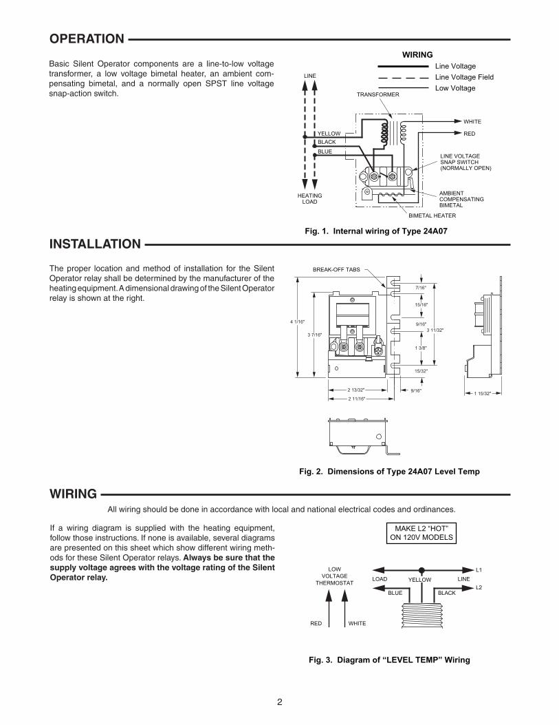
If a wiring diagram is supplied with the heating equipment, follow those instructions. If none is available, several diagrams are presented on this sheet which show different wiring meth-ods for these Silent Operator relays. Always be sure that the supply voltage agrees with the voltage rating of the Silent operator relay.
The proper location and method of installation for the Silent Operator relay shall be determined by the manufacturer of the heating equipment. A dimensional drawing of the Silent Operator relay is shown at the right.
Basic Silent Operator components are a line-to-low voltage transformer, a low voltage bimetal heater, an ambient com-pensating bimetal, and a normally open SPST line voltage snap-action switch.
inSTAllATion
operATion
Fig. 1. Internal wiring of Type 24A07
WHITE
WIRINGLine VoltageLine Voltage FieldLow Voltage
TRANSFORMER
YELLOWBLACK
BLUE
HEATINGLOAD
BIMETAL HEATER
AMBIENTCOMPENSATINGBIMETAL
LINE VOLTAGESNAP SWITCH(NORMALLY OPEN)
RED
LINE
7/16"
15/16"
1 3/8"
15/32"
9/16"
2 11/16"
2 13/32" 9/16"
3 11/32"
4 1/16"
1 15/32"
3 7/16"
Fig. 2. Dimensions of Type 24A07 Level Temp
BREAK-OFF TABS
Fig. 3. Diagram of “LEVEL TEMP” Wiring
RED WHITE
LOWVOLTAGE
THERMOSTAT
BLACKBLUE
ENILDAOL YELLOW
L1
L2
MAKE L2 “HOT”ON 120V MODELS
3
WirinG conT.
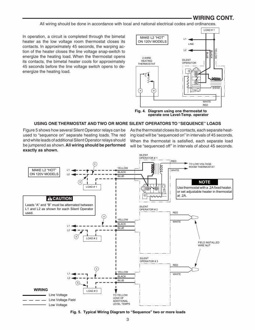
In operation, a circuit is completed through the bimetal heater as the low voltage room thermostat closes its contacts. In approximately 45 seconds, the warping ac-tion of the heater closes the line voltage snap-switch to energize the heating load. When the thermostat opens its contacts, the bimetal heater cools for approximately 45 seconds before the line voltage switch opens to de-energize the heating load.
All wiring should be done in accordance with local and national electrical codes and ordinances.
uSinG one THermoSTAT AnD TWo or more SilenT operATorS To “Sequence” loADS
Figure 5 shows how several Silent Operator relays can be used to “sequence on” separate heating loads. The red and white leads of additional Silent Operator relays should be jumpered as shown. All wiring should be performed exactly as shown.
As the thermostat closes its contacts, each separate heat-ing load will be “sequenced on” in intervals of 45 seconds.When the thermostat is satisfied, each separate load will be “sequenced off” in intervals of about 45 seconds.
WR
Fig. 4. Diagram using one thermostat tooperate one Level-Temp. operator
WHITERED
SILENTOPERATOR
L1
L2
LINE
LOAD # 1
YE
LLOW
BLA
CK
BLU
E
2-WIREHEATING
THERMOSTAT
MAKE L2 “HOT”ON 120V MODELS
Fig. 5. Typical Wiring Diagram to “Sequence” two or more loads
A
B
A
B
A
B
WIRINGLine VoltageLine Voltage FieldLow Voltage
L1
L2
LOAD # 1
BLACKBLUE
YELLOW
BLACKBLUE
YELLOW
BLACKBLUE
YELLOW
SILENTOPERATOR # 1
RED
WHITE
RED
WHITE
RED
WHITE
TO LOW VOLTAGEROOM THERMOSTAT
NOTEUse thermostat with a .2A fixed heater,or set adjustable heater in thermostatat .2A.
LOAD # 2
SILENTOPERATOR # 2
L1
L2
FIELD INSTALLEDWIRE NUT
LOAD # 3
SILENTOPERATOR # 3
L1
L2
TO YELLOWLEAD OFADDITIONALLEVEL TEMPS
Leads “A” and “B” must be alternated betweenL1 and L2 as shown for each Silent Operatorused.
CAUTION
MAKE L2 “HOT”ON 120V MODELS

White-Rodgers is a business of Emerson Electric Co.
The Emerson logo is a trademark and service mark of Emerson Electric Co.
www.white-rodgers.comwww.emersonclimate.com

White-Rodgers est une affaire d’Emerson Electric Co.
Le logo d’Emerson est une marque de commerce et une marquede service d’Emerson Electric Co.
www.white-rodgers.comwww.emersonclimate.com
3
câblage (suite)
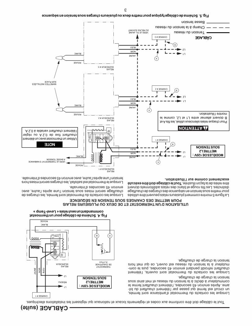
Lorsque les contacts du thermostat d’ambiance sont fermés, un circuit est fermé qui passe par l’élément chauffant du bil-ame. Après environ 45 secondes, l’élément chauffant ferme le commutateur à déclic à la tension du réseau et met ainsi sous tension la charge de chauffage. Lorsque les contacts du thermostat sont ouverts, l’élément chauffant refroidit pendant environ 45 secondes, puis le com-mutateur à la tension du réseau est ouvert, ce qui met hors tension la charge de chauffage.
Tout le câblage doit être conforme aux codes et règlements locaux et nationaux qui régissent les installations électriques.
Utilisation d’Un thermostat et de deUx oU plUsieUrs relais poUr mettre des charges soUs tension en séqUence
La figure 5 montre comment plusieurs relais peuvent être utilisés pour mettre sous tension en séquence des charges de chauffage distinctes. Les fils rouge et blanc des relais additionnels doivent être reliés de la façon illustrée. tout le câblage doit être exécuté exactement comme sur l’illustration.
Lorsque les contacts du thermostat sont fermés, les charges de chauffage seront mises sous tension l’une après l’autre, avec environ 45 secondes d’intervalle. Lorsque le thermostat est satisfait, les charges seront mises hors tension l’une après l’autre, avec environ 45 secondes d’intervalle.
W R
Fig. 4. Schéma de câblage pour un thermostatcommandant un seul relais «Level-Temp»
RELAISSILENCIEUX
CHARGE # 1
MODÈLES DE 120V:METTRE L2
SOUS TENSION
JAU
NE
NO
IR
BLE
U
L1
L2
RÉSEAU
THERMOSTATDE CHAUFFAGE
À 2 FILS
BLANC
ROUGE
Fig. 5. Schéma de câblage typique pour mettre deux ou plusieurs charges sous tension en séquence
A
B
A
B
A
B
CHARGE # 1
NOIR
BLEU
JAUNE
NOIR
BLEU
JAUNE
NOIR
BLEU
JAUNE
RELAISSILENCIEUX # 1
ROUGE
BLANC
ROUGE
BLANC
ROUGE
BLANC
NOTEUtiliser un thermostat avec un élémentchauffant fixe de 0,2A ou réglerl’élément chauffant variable à 0,2A.
CHARGE # 2
RELAISSILENCIEUX # 2
L1
L2
CHARGE # 3
RELAISSILENCIEUX # 3
L1
L2
Pour chaque relais silencieux utilisé, les fils A etB doivent alterner entre L1 et L2, comme lemontre l’illustration.
ATTENTION
MODÈLES DE 120V:METTRE L2
SOUS TENSION
L1
L2
VERS LE FIL JAUNEDU RELAIS SUIVANT
MARETTES INSTALLÉESSUR PLACE
VERS LE THERMOSTAT D’AMBIANCEÀ BASSE TENSION
CÂBLAGETension du réseauChamp à la tension du réseauBasse tension
2
7/16"
15/16"
1 3/8"
15/32"
9/16"
2 11/16"
2 13/32" 9/16"
3 11/32"
4 1/16"
1 15/32"
3 7/16"
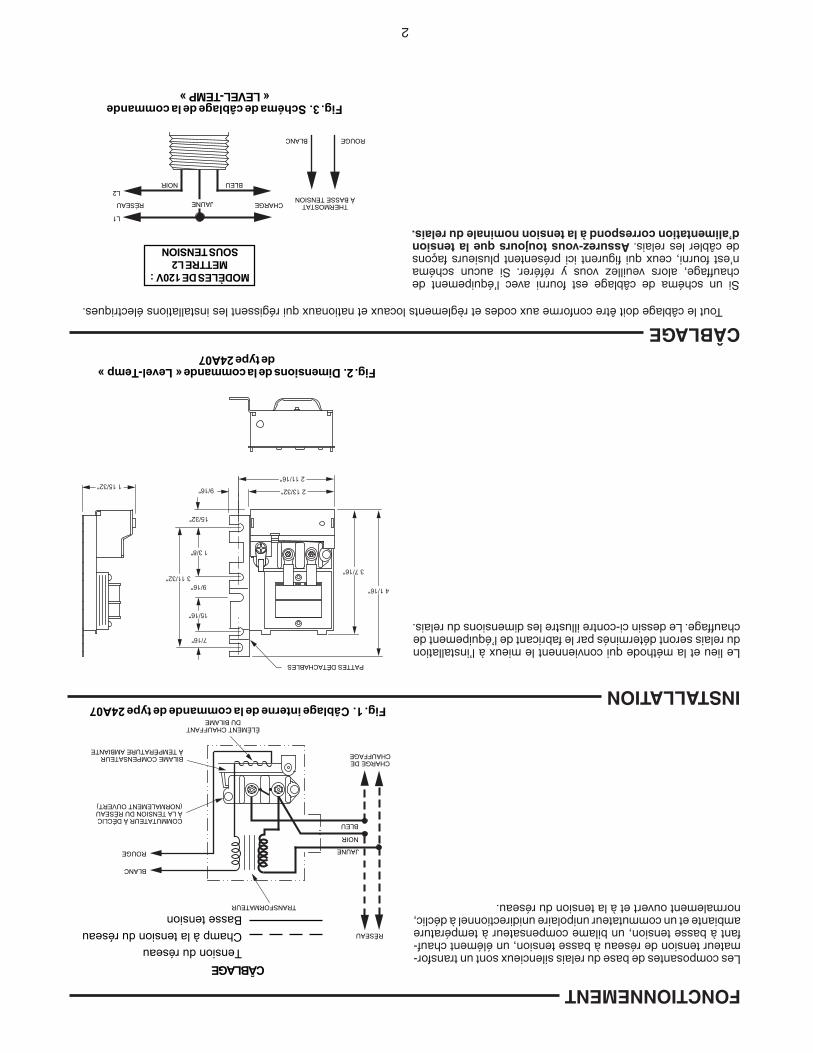
Fig. 2. Dimensions de la commande «Level-Temp»de type 24A07
PATTES DÉTACHABLES
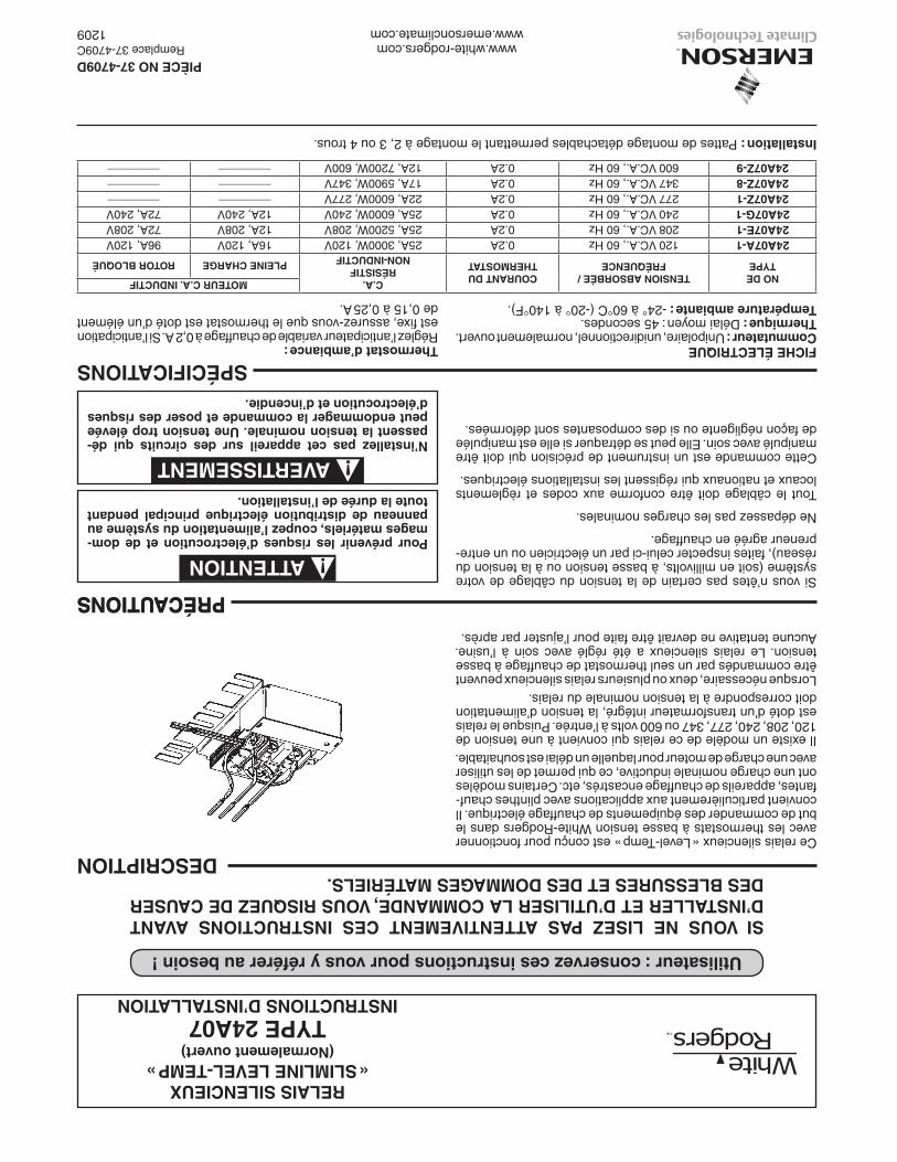
câblage Tout le câblage doit être conforme aux codes et règlements locaux et nationaux qui régissent les installations électriques.
Si un schéma de câblage est fourni avec l’équipement de chauffage, alors veuillez vous y référer. Si aucun schéma n’est fourni, ceux qui figurent ici présentent plusieurs façons de câbler les relais. assurez-vous toujours que la tension d’alimentation correspond à la tension nominale du relais.
Le lieu et la méthode qui conviennent le mieux à l’installation du relais seront déterminés par le fabricant de l’équipement de chauffage. Le dessin ci-contre illustre les dimensions du relais.
Les composantes de base du relais silencieux sont un transfor-mateur tension de réseau à basse tension, un élément chauf-fant à basse tension, un bilame compensateur à température ambiante et un commutateur unipolaire unidirectionnel à déclic, normalement ouvert et à la tension du réseau.
installation
fonctionnement
Fig. 1. Câblage interne de la commande de type 24A07
BLANC
CÂBLAGETension du réseauChamp à la tension du réseauBasse tension
TRANSFORMATEUR
JAUNE
NOIR
BLEU
CHARGE DECHAUFFAGE
COMMUTATEUR À DÉCLICÀ LA TENSION DU RÉSEAU(NORMALEMENT OUVERT)
ROUGE
RÉSEAU
BILAME COMPENSATEURÀ TEMPÉRATURE AMBIANTE
ÉLÉMENT CHAUFFANTDU BILAME
Fig. 3. Schéma de câblage de la commande«LEVEL-TEMP»
ROUGE
BLEU
JAUNE
L1
L2
MODÈLES DE 120V:METTRE L2
SOUS TENSION
RÉSEAU CHARGE THERMOSTATÀ BASSE TENSION
BLANC
NOIR
Utilisateur : conservez ces instructions pour vous y référer au besoin !
si voUs ne lisez pas attentivement ces instrUctions avant d’installer et d’Utiliser la commande, voUs risqUez de caUser des blessUres et des dommages matériels.
spécifications
descriptionCe relais silencieux « Level-Temp » est conçu pour fonctionner avec les thermostats à basse tension White-Rodgers dans le but de commander des équipements de chauffage électrique. Il convient particulièrement aux applications avec plinthes chauf-fantes, appareils de chauffage encastrés, etc. Certains modèles ont une charge nominale inductive, ce qui permet de les utiliser avec une charge de moteur pour laquelle un délai est souhaitable. Il existe un modèle de ce relais qui convient à une tension de 120, 208, 240, 277, 347 ou 600 volts à l’entrée. Puisque le relais est doté d’un transformateur intégré, la tension d’alimentation doit correspondre à la tension nominale du relais. Lorsque nécessaire, deux ou plusieurs relais silencieux peuvent être commandés par un seul thermostat de chauffage à basse tension. Le relais silencieux a été réglé avec soin à l’usine. Aucune tentative ne devrait être faite pour l’ajuster par après.
AVERTISSEMENT !n’installez pas cet appareil sur des circuits qui dé-passent la tension nominale. Une tension trop élevée peut endomma ger la commande et poser des risques d’électro cution et d’incendie.
ATTENTION !pour prévenir les risques d’électrocution et de dom-mages matériels, coupez l’alimentation du système au panneau de distribution électrique principal pendant toute la durée de l’installation.
precaUtions précaUtionsSi vous n’êtes pas certain de la tension du câblage de votre système (soit en millivolts, à basse tension ou à la tension du réseau), faites inspecter celui-ci par un électricien ou un entre-preneur agréé en chauffage.
Ne dépassez pas les charges nominales.
Tout le câblage doit être conforme aux codes et règlements locaux et nationaux qui régissent les installations électriques.
Cette commande est un instrument de précision qui doit être manipulé avec soin. Elle peut se détraquer si elle est manipulée de façon négligente ou si des composantes sont déformées.
fiche électriqUe commutateur : Unipolaire, unidirectionnel, normalement ouvert. thermique : Délai moyen : 45 secondes. température ambiante : -24° à 60°C (-20° à 140°F).
thermostat d’ambiance : Réglez l’anticipateur variable de chauffage à 0,2 A. Si l’anticipation est fixe, assurez-vous que le thermostat est doté d’un élément de 0,15 à 0,25 A.
relais silencieUx « slimline level-temp »
(normalement ouvert)
type 24a07instrUctions d’installation
installation : Pattes de montage détachables permettant le montage à 2, 3 ou 4 trous.
www.white-rodgers.comwww.emersonclimate.com
piÈce no 37-4709dRemplace 37-4709C
1209
no detype
tension absorbée /fréqUence
coUrant dUthermostat
c.a. résistif
non-indUctif
moteUr c.a. indUctif
pleine chargerotor bloqUé
24a07a-1120 VC.A., 60 Hz0.2A25A, 3000W, 120V16A, 120V96A, 120V24a07e-1208 VC.A., 60 Hz0.2A25A, 5200W, 208V12A, 208V72A, 208V24a07g-1240 VC.A., 60 Hz0.2A25A, 6000W, 240V12A, 240V72A, 240V24a07z-1277 VC.A., 60 Hz0.2A22A, 6000W, 277V________________
24a07z-8347 VC.A., 60 Hz0.2A17A, 5900W, 347V________________
24a07z-9600 VC.A., 60 Hz0.2A12A, 7200W, 600V________________