type 3271 pneumatic actuators 1000, 1400-120, 2800 and 2x ... · 2 t 8310-2/7 en principle of...
TRANSCRIPT
Data Sheet T 8310-2/7 EN
Edition April 2018Associated Information Sheet T 8300Information Sheet for control valves T 8000-1Data Sheet for actuators ≤750 cm² T 8310-1
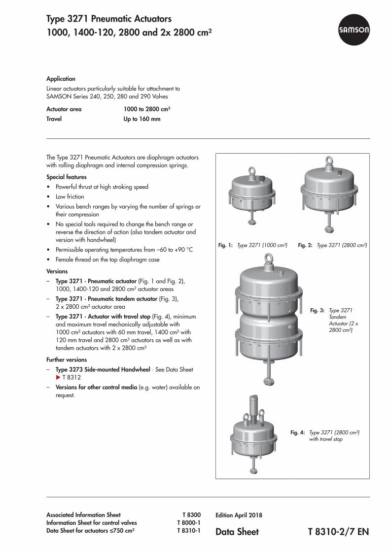
The Type 3271 Pneumatic Actuators are diaphragm actuators with rolling diaphragm and internal compression springs.
Special features • Powerful thrust at high stroking speed • Low friction • Various bench ranges by varying the number of springs or
their compression • No special tools required to change the bench range or
reverse the direction of action (also tandem actuator and version with handwheel)
• Permissible operating temperatures from –60 to +90 °C • Female thread on the top diaphragm case
Versions – Type 3271 · Pneumatic actuator (Fig. 1 and Fig. 2),
1000, 1400‑120 and 2800 cm² actuator areas – Type 3271 · Pneumatic tandem actuator (Fig. 3),
2 x 2800 cm² actuator area – Type 3271 · Actuator with travel stop (Fig. 4), minimum
and maximum travel mechanically adjustable with 1000 cm² actuators with 60 mm travel, 1400 cm² with 120 mm travel and 2800 cm² actuators as well as with tandem actuators with 2 x 2800 cm²
Further versions – Type 3273 Side-mounted Handwheel · See Data Sheet u T 8312
– Versions for other control media (e.g. water) available on request.
Fig. 1: Type 3271 (1000 cm²) Fig. 2: Type 3271 (2800 cm²)
Fig. 3: Type 3271 Tandem Actuator (2 x 2800 cm²)
Fig. 4: Type 3271 (2800 cm²) with travel stop
Type 3271 Pneumatic Actuators 1000, 1400-120, 2800 and 2x 2800 cm²
ApplicationLinear actuators particularly suitable for attachment to SAMSON Series 240, 250, 280 and 290 Valves
Actuator area 1000 to 2800 cm²Travel Up to 160 mm

2 T 8310-2/7 EN
Principle of operationThe signal pressure pst creates the force F = pst · A at the dia‑phragm surface A which is opposed by the springs (10) in the actuator. The bench range is determined by the number of springs used and their compression, taking into account the rated travel. The travel H is proportional to the signal pressure pst. The direction of action of the actuator stem (7) depends on how the springs are installed in the actuator.The stem connector (26) connects the actuator stem (7) with the plug stem of the valve.The adjustable mechanical travel stop (Fig. 9) is suitable for actuators with 1000, 1400‑120 and 2800 cm² actuator areas as well as tandem actuators. Using the travel stop, the actua‑tor travel can be limited by up to 50 % in both directions (ac‑tuator stem extends or retracts) and permanently adjusted.The tandem actuator (Fig. 7) contains two coupled dia‑phragms; they produce a positioning force that is twice as high as the force of a single actuator.
Direction of actionActuators are available with the following directions of action: – Actuator stem extends (FA): the springs cause the actuator
stem to move to the lower end position when the dia‑phragm is relieved of pressure or when the supply air fails.
– Actuator stem retracts (FE): the springs cause the actuator stem to retract when the diaphragm is relieved of pressure or when the supply air fails.
Throttling or on/off serviceThe Type 3271 Pneumatic Actuators are designed for a maxi‑mum supply pressure of 6 bar when used for throttling ser‑vice.In on/off service and special actuators for throttling service, the supply pressure must be limited.For the direction of action "actuator stem retracts (FE)", the permissible supply pressure must not exceed the upper bench range value by more than 3 bar:
Signal pressure range Fail-safe action Max. supply
pressure
0.2 to 1.0 barActuator stem
retracts
4 bar
0.4 to 2.0 bar 5 bar
0.6 to 3.0 bar 6 bar
With the direction of action "actuator stem extends" and trav‑el stop, the supply pressure must not exceed the upper bench range value by more than 1.5 bar.
16
10
8
7
S
2
4
Fig. 5: Type 3271 with 1000 cm² actuator area
S
1
16
26
7
10
4
8
16
2
S
Fig. 6: Type 3271, 1400-120 cm² with female thread on the top diaphragm case

T 8310-2/7 EN 3
Legend for Fig. 5 to Fig. 7
1 Top diaphragm case2 Bottom diaphragm case4 Diaphragm7 Actuator stem8 Ring nut10 Springs16 Vent plug80 Diaphragm case (tandem actuator)81 Actuator stemS Signal pressure connection
10
S
S
16
4
16
1
16
S
2
168
26
S
7
80
81
Fig. 7: Tandem actuator with 2 x 2800 cm² actuator area with female thread on the top diaphragm case

4 T 8310-2/7 EN
Table 1: Technical data
Table 1.1: Type 3271 Pneumatic Actuator
Version cm² 1000 1400-120 2800 2 x 2800
Max. supply pressure 6 bar 1)
Permissible ambient temperaturesDiaphragm material NBR: –35 to +90 °C 2) 3)
Diaphragm material PVMQ: –60 to +90 °C 3)
Compliance
Materials
Actuator stem 1.4548.4 1.4404 1.4548.4
Actuator stem sealingNBR NBR
EPDM PVMQ
Housing and associated ambient temperature
1.0982 S460 MCSheet steel, painted
≥–60 °C
EN‑JS1030 (GGG‑40) 4)
Spheroidal graphite ironMax. 100 °C
1.5638/A352 LC3Painted cast steel
≥–60 °C
1) Observe supply air restrictions.2) In on/off service, lowest temperature restricted to –20 °C3) Install vent plug (u AB 07) for temperatures below –20 °C.4) Not with diaphragm material PVMQ
Table 1.2: Versions
Implementation 1000 cm² 1400-120 cm² 2800 cm² 2 x 2800 cm²
Mechanical travel stops on both sides • • • •
Additional handwheel, 50 kN • – – –
Additional handwheel, 80 kN • • 1) • 1)
(max. 3 bar) –
Additional handwheel, 150 kN – • • •
Throttling or on/off service • • • •
1) Max. 60 mm
T 8310-2/7 EN 5
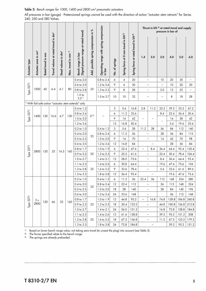
Table 2: Bench ranges for 1000, 1400 and 2800 cm² pneumatic actuatorsAll pressures in bar (gauge) · Pretensioned springs cannot be used with the direction of action “actuator stem retracts” for Series 240, 250 and 280 Valves.
Actu
ator
type
Actu
ator
are
a in
cm²
Rate
d tra
vel i
n m
m
Trav
el v
olum
e at
rate
d tra
vel i
n dm
³
Dead
vol
ume
in d
m³
Max
. tra
vel i
n m
m 1)
Benc
h ra
nge
in b
ar(S
igna
l pre
ssur
e ra
nge
at ra
ted
trave
l)
Add.
pos
sible
sprin
g co
mpr
essio
n in
%
Ope
ratin
g ra
nge
with
sprin
g co
mpr
essio
n in
bar
No.
of s
prin
gs
Sprin
g fo
rce
at 0
mm
trav
el in
kN
2)
Sprin
g fo
rce
at ra
ted
trave
l in
kN 2
)
Thrust in kN 2) at rated travel and supply pressure in bar of
1.4 2.0 3.0 4.0 5.0 6.0
Type
327
1
1000 60 6.4 6.1 80
0.4 to 2.0
25
0.8 to 2.4 6 4 20 – 10 20 30 –
0.6 to 3.0 1.2 to 3.6 9 6 30 – – 10 20 30
0.8 to 2.8 1.3 to 3.3 9 8 28 – 2.0 12 22 –
1.0 to 3.2 *) 1.5 to 3.7 10 10 32 – – 8 18 28
*) With fail‑safe action "actuator stem extends" only
Type
327
1
1400 120 16.6 4.7 130
0.4 to 1.2
0 3) –
3 5.6 16.8 2.8 11.2 25.2 39.2 53.2 67.2
0.8 to 2.4 6 11.2 33.6
– –
8.4 22.4 36.4 50.4
1.0 to 3.0 9 14 42–
14 28 42
1.2 to 3.6 12 16.8 50.4 5.6 19.6 33.6
Type
327
1
2800 120 33 16.5 160
0.2 to 1.0
25
0.4 to 1.2 3 5.6 28 11.2 28 56 84 112 140
0.4 to 2.0 0.8 to 2.4 6 11.2 56 – 28 56 84 112
0.5 to 2.5 1.0 to 3.0 9 14 70 – 14 42 70 98
0.6 to 3.0 1.2 to 3.6 12 16.8 84 – 28 56 84
0.8 to 1.7
25
1.0 to 1.9 6 22.4 47.6 – 8.4 36.4 64.4 92.4 120.4
0.9 to 2.2 1.2 to 2.5 9 25.2 61.6 – 22.4 50.4 78.4 106.4
1.0 to 2.7 1.4 to 3.1 12 28.0 75.6 – 8.4 36.4 64.4 92.4
1.1 to 2.3
25
1.4 to 2.6 6 30.8 64.4 – 19.6 47.6 75.6 104
1.2 to 2.8 1.6 to 3.2 9 33.6 78.4 – 5.6 33.6 61.6 89.6
1.3 to 3.3 1.8 to 3.8 12 36.4 92.4 – 19.6 47.6 75.6
Type
327
1
2 x 2800 120 66 33 160
0.2 to 1.0
25
0.4 to 1.2 6 11.2 56 22.4 56 112 168 224 280
0.4 to 2.0 0.8 to 2.4 12 22.4 112 – 56 112 168 224
0.5 to 2.5 1.0 to 3.0 18 28 140 – 28 84 140 196
0.6 to 3.0 1.2 to 3.6 24 33.6 168 – 56 112 168
0.8 to 1.7
25
1.0 to 1.9 12 44.8 95.2 – 16.8 74.8 128.8 184.8 240.8
0.9 to 2.2 1.2 to 2.5 18 50.4 123.2 – 44.8 100.8 156.8 212.8
1.0 to 2.7 1.4 to 3.1 24 56.0 151.2 – 16.8 72.8 128.8 184.8
1.1 to 2.3
25
1.4 to 2.6 12 61.6 128.8 – 39.2 95.2 151.2 208
1.2 to 2.8 1.6 to 3.2 18 67.2 156.8 – 11.2 67.2 123.2 179.2
1.3 to 3.3 1.8 to 3.8 24 72.8 184.8 – 39.2 95.2 151.2
1) Based on lower bench range value, not taking zero travel (to unseat the plug) into account (see Table 3).2) The forces specified relate to the bench range.3) The springs are already preloaded.

6 T 8310-2/7 EN
Table 3: Dimensions and weights for versions without handwheel
Actuator Type 3271
Refer to Fig. 1 · Fig. 8 Fig. 10 Fig. 2 · Fig. 10 Fig. 3 · Fig. 11
Actuator area cm² 1000 1400-120 2800 2 x 2800
Height
H 313 470 585 1085
H4ratedFA 165 285 315
H4maxFA 169 288 325
H4maxFE 185 315 355
H6 54 85 85
H7 1) 90 128 128
Travel limitation H8 220 500 500
DiameterØD 462 534 770
ØD2 22 40 40
Ød (thread) M60x1.5 M100x2 M100x2
Pneumatic connection (optional)
a G ¾/¾ NPT G 1/1 NPT G 1/1 NPT
a2 – –
Weight [kg]
Without handwheel 80 175 450 950
1) Height of eyebolt according to DIN 580. Height of the swivel lifting hook may differ.

T 8310-2/7 EN 7
H4
a
HH7
H6
ØD2Ød
ØD
a
a
a
HH8
H6 H4
ØD
ØD2
Ød
Fig. 8: Type 3271, 1000 cm² Fig. 9: Type 3271, 1000 cm² with mechanical travel stop
H7
ØD Ød
H4H6
a
a
ØD2
a
a
H
H7a
H6
H4H
a
a
a
ØDØd
ØD2
Fig. 10: Type 3271, 1400-120 cm² Fig. 11: Type 3271 as tandem actuator

Specifications subject to change without notice
SAMSON AG · MESS- UND REGELTECHNIK Weismüllerstraße 3 · 60314 Frankfurt am Main, Germany Phone: +49 69 4009-0 · Fax: +49 69 4009-1507 [email protected] · www.samson.de T 8310-2/7 EN 20
18‑0
4‑25
· En
glish
Ordering text
Actuator Type 3271 Actuator area … cm² Travel … mm
Optional Travel limitationTandem actuator
Signal pressure range ... barDirection of action Actuator stem extends (FA)
Actuator stem retracts (FE)Signal pressure connection
G .../... NPT
Rolling diaphragm NBR/PVQM/EPDM (1000 cm² only)
AccessoriesThe pneumatic actuators with 1000, 1400‑120, 2800 und 2 x 2800 cm² actuator area have a female thread on the top diaphragm case to allow an eyebolt or swivel lifting hook to be screwed into it. The eyebolt can be used to vertically lift the actuator and is included in the scope of delivery. The swivel lifting hook is designed for setting a control valve assembly upright or for lifting the actuator without valve. The swivel lift‑ing hook can be ordered (accessories).
Item no.
Actuator area Ring bolt(DIN 580) Swivel lifting hook
1000 cm² 8325‑0135 8442‑1018
1400‑120 cm²2800 cm²
2x 2800 cm²8325‑1101 8442‑1019
List of documentation
Device type Actuator area in cm² Data sheet Mounting and operating instructions
Types 3271 and 3277 Pneumatic Actuators
120
u T 8310‑1/4/5/6
u EB 8310‑1
240 · 350 · 700 u EB 8310‑6
175v2 · 350v2 · 750v2 u EB 8310‑5
355v2 u EB 8310‑4
Type 3271 Pneumatic Actuator
1000Included in this data sheet
u EB 8310‑2
1400‑120 · 2800 · 2 x 2800 u EB 8310‑7
1400‑60 u T 8310‑3 u EB 8310‑3
1400‑250 u T 8310‑8 u EB 8310‑8