type b service referewnce manual
TRANSCRIPT
Type B Service
Reference Manual

Document Title: Type B Service Reference ManualDocument Code: 113A-bis
Edition Date: January, 2000
Further copies of this document can be ordered by sending a message to SITA address PARJFXS or by written request to:
SITA Mail and Documentation Services18 rue Paul-Lafargue92904 Paris-La D�fense 10France
© SITA, 1999
The information contained in this document is the property of SITA. No part of this document may be reproduced, stored in a retrieval system, or transmitted in any form, or by any means; electronic, mechanical, photocopying, recording, or otherwise, without the prior written permission of SITA. Legal action will be taken against any infringement.
The information contained in this document is subject to change without notice and does not carry any contractual obligation for SITA. SITA reserves the right to make changes to any products or services described in this document at any time without notice. SITA shall not be held responsible for the direct or indirect consequences of the use of the information contained in this document.
No reproduction permitted.
All rights reserved.

113A-0100-bis
Preface
This edition of the Type B Service Reference Manual supersedes the SITAMAIL Type B Reference Manual issued in May 1995.
This manual is intended for new member companies to SITA, and all SITA and member company personnel involved in transmitting and receiving Type B messages, either wholly or partly over the SITA Network.
The manual establishes the telecommunication standards for Type B message handling used on the SITA Network. These standards will assist new members in making their physical connection(s) to the SITA Network and are essential to operations staff in obtaining maximum efficiency and security when using the SITA Network.
It is recommended that SITA member companies operating their own facilities use these rules as a guide for standardization.
About This Book
The manual is divided as follows:
¥ Chapters 1-5 describe the standards that are applicable to all Type B messages, independent of the type of connection used.
¥ Chapters 6-20 give information specific to each type of connection used for Type B.
¥ Appendix A defines the standard translation between the character sets used for Type B messages.
¥ Glossary - defines the terminology used in the manual.
i
Preface
Summary of Changes to this Edition
In addition to updates to reflect the evolution of the Type B Network topology since the last edition, the following major updates have been made:
¥ The document title has been changed from SITAMAIL Type B Reference Manual to Type B Service Reference Manual.
¥ Addition of chapters on three new connection types:- MATIP-Type B- MQ-Type B- Web-Type B
¥ Removal of connection types that are no longer used for new connections.
ii 113A-0100-bis

113A-0100-bis
Contents
1 General Information
What is Type B? . . . . . . . . . . . . . . . . . . . . . . . . 1-1Overview of Type B Features . . . . . . . . . . . . . . . . . 1-2
Authorisation to use the SITA Network . . . . . . . . . . . . . . 1-5The Type B Service . . . . . . . . . . . . . . . . . . . . . . . 1-5
MHS (Message Handling System) . . . . . . . . . . . . . . . 1-6Availability of Service . . . . . . . . . . . . . . . . . . . . 1-6Time System . . . . . . . . . . . . . . . . . . . . . . . . 1-7
Character Codes used by Service . . . . . . . . . . . . . . . . . 1-7Acceptable Messages . . . . . . . . . . . . . . . . . . . . . . 1-7
Message Length . . . . . . . . . . . . . . . . . . . . . . 1-7Confidentiality . . . . . . . . . . . . . . . . . . . . . . . . 1-8
Secrecy Undertaking . . . . . . . . . . . . . . . . . . . . 1-8Entry to Centres and Stations . . . . . . . . . . . . . . . . . 1-8Traffic Information . . . . . . . . . . . . . . . . . . . . . 1-8
Prohibited Transmission . . . . . . . . . . . . . . . . . . . . 1-8
2 Message Formats
Representation of Non-printing Characters . . . . . . . . . . . 2-2ASCII/Baudot/ASCII Translation . . . . . . . . . . . . . . . 2-3
Component Sections . . . . . . . . . . . . . . . . . . . . . . 2-3Heading Section . . . . . . . . . . . . . . . . . . . . . . . . 2-3Address Section . . . . . . . . . . . . . . . . . . . . . . . . 2-4
Diversion Line (optional) . . . . . . . . . . . . . . . . . . 2-4Short Address Line (optional) . . . . . . . . . . . . . . . . 2-8Normal Address Line (mandatory) . . . . . . . . . . . . . . 2-9
Origin Section . . . . . . . . . . . . . . . . . . . . . . . . . 2-12Originator Indicator (mandatory) . . . . . . . . . . . . . . . 2-12
iii

Contents
Double Signature (if required) . . . . . . . . . . . . . . . . 2-13Message Identity (optional) . . . . . . . . . . . . . . . . . 2-14
Text Section . . . . . . . . . . . . . . . . . . . . . . . . . 2-15Start-of-Text Signal (mandatory) . . . . . . . . . . . . . . . 2-15Text . . . . . . . . . . . . . . . . . . . . . . . . . . . 2-16Indicators used in the Text . . . . . . . . . . . . . . . . . 2-18End-of-Text Signal . . . . . . . . . . . . . . . . . . . . . 2-21
Ending Section . . . . . . . . . . . . . . . . . . . . . . . . 2-21Cancelling a Partly-transmitted Message . . . . . . . . . . . . . 2-21
3 Transmission and Protection
Message Acceptance . . . . . . . . . . . . . . . . . . . . . . . 3-1Cancelled Messages . . . . . . . . . . . . . . . . . . . . . . . 3-2Format Error . . . . . . . . . . . . . . . . . . . . . . . . . . 3-2
Check on Address Section . . . . . . . . . . . . . . . . . . . 3-3Check on Origin Section . . . . . . . . . . . . . . . . . . . 3-4Missing End-of-Text/End-of-Message Signal . . . . . . . . . . 3-4Miscellaneous . . . . . . . . . . . . . . . . . . . . . . . . 3-5Multiple Errors . . . . . . . . . . . . . . . . . . . . . . . 3-6
Invalid Origin or Destination . . . . . . . . . . . . . . . . . . . 3-6Unauthorised Input . . . . . . . . . . . . . . . . . . . . . 3-7Unknown Destination Address . . . . . . . . . . . . . . . . 3-7Routing Errors . . . . . . . . . . . . . . . . . . . . . . . . 3-9
Messages Accepted by the Service . . . . . . . . . . . . . . . . 3-10Sequence Indicator of Message Parts . . . . . . . . . . . . . . . 3-10Routing . . . . . . . . . . . . . . . . . . . . . . . . . . . 3-12
The Role of the SITA MHS . . . . . . . . . . . . . . . . . 3-13Order of Transmission . . . . . . . . . . . . . . . . . . . . . 3-13Traffic Protection and Continuity Control . . . . . . . . . . . . 3-14
Serial Numbering . . . . . . . . . . . . . . . . . . . . . 3-14Periodic Continuity Check . . . . . . . . . . . . . . . . . 3-15Continuity Check generated by SITA MHS . . . . . . . . . . 3-16
Additional Rules for Delivery of SS and QS Messages . . . . . . . 3-17
4 Machine-readable Messages
Service Messages to a SITA MHS . . . . . . . . . . . . . . . . . 4-1
iv 113A-0100-bis
Contents
Unacceptable Messages . . . . . . . . . . . . . . . . . . . 4-2BACKLOG . . . . . . . . . . . . . . . . . . . . . . . . . 4-2CONT OFF . . . . . . . . . . . . . . . . . . . . . . . . . 4-3CONT ON . . . . . . . . . . . . . . . . . . . . . . . . . 4-4GA . . . . . . . . . . . . . . . . . . . . . . . . . . . . 4-5RPT ALL . . . . . . . . . . . . . . . . . . . . . . . . . 4-6RPT BTN (serial number) . . . . . . . . . . . . . . . . . . 4-7RPT BTN (time of delivery) . . . . . . . . . . . . . . . . . 4-9RPT ONE . . . . . . . . . . . . . . . . . . . . . . . . . 4-10STAT . . . . . . . . . . . . . . . . . . . . . . . . . . . 4-11STOP . . . . . . . . . . . . . . . . . . . . . . . . . . . 4-12
Messages to SITA Services . . . . . . . . . . . . . . . . . . . 4-13FAX . . . . . . . . . . . . . . . . . . . . . . . . . . . . 4-13GPS DIRECTORY REQUEST . . . . . . . . . . . . . . . . . 4-14ROUT (address) . . . . . . . . . . . . . . . . . . . . . . 4-15RTB . . . . . . . . . . . . . . . . . . . . . . . . . . . . 4-18RTX (telex number) . . . . . . . . . . . . . . . . . . . . . 4-18RTX (city) . . . . . . . . . . . . . . . . . . . . . . . . . 4-19RTX HELP . . . . . . . . . . . . . . . . . . . . . . . . . 4-20
5 Gateways
AFTN (Aeronautical Fixed Telecommunications Network) . . . . . 5-1Message Transfer from SITA Network to AFTN . . . . . . . . . 5-1Message Transfer from AFTN to SITA Network . . . . . . . . . 5-5AFTN to AFTN over the SITA Network . . . . . . . . . . . . 5-7
X.400 . . . . . . . . . . . . . . . . . . . . . . . . . . . . . 5-8Sending Type B Messages to X.400 Destinations . . . . . . . . . 5-8Document Transfer from Type B to X.400 . . . . . . . . . . . 5-11Receiving X.400 Messages . . . . . . . . . . . . . . . . . . 5-12Messages Received from X.400 Systems . . . . . . . . . . . . 5-12Rejected Messages . . . . . . . . . . . . . . . . . . . . . 5-13Interconnected X.400 Services . . . . . . . . . . . . . . . . 5-16
6 Bridges
BFAX Service . . . . . . . . . . . . . . . . . . . . . . . . . 6-1Messages Intended for Delivery to Fax Machines . . . . . . . . 6-2Delivery to Fax Destination . . . . . . . . . . . . . . . . . 6-4
113A-0100-bis v
Contents
Delivery Notification . . . . . . . . . . . . . . . . . . . . . 6-5PTN (Public Telegraph Network) . . . . . . . . . . . . . . . . . 6-8
Messages for Transfer to the PTN . . . . . . . . . . . . . . . 6-8Handling at the Transfer Station . . . . . . . . . . . . . . . . 6-9Telegrams for Transfer to the SITA Network . . . . . . . . . . 6-12Handling at the Transfer Station . . . . . . . . . . . . . . . 6-12
RTX (Relay To Public Telex) . . . . . . . . . . . . . . . . . . 6-14Type B Messages for RTX . . . . . . . . . . . . . . . . . . 6-14RTX Service Centres . . . . . . . . . . . . . . . . . . . . 6-16Delivery to Telex Machines . . . . . . . . . . . . . . . . . 6-18RTX Help . . . . . . . . . . . . . . . . . . . . . . . . . 6-18
7 Servers
RTB (Relay Through Broadcast) . . . . . . . . . . . . . . . . . . 7-1RTB Broadcast Lists . . . . . . . . . . . . . . . . . . . . . 7-1RTB Commands . . . . . . . . . . . . . . . . . . . . . . . 7-2RTB Message Format . . . . . . . . . . . . . . . . . . . . . 7-5
8 Overview of Connection Types
Hand-Delivery . . . . . . . . . . . . . . . . . . . . . . . . . 8-2
9 AX.25
General Description . . . . . . . . . . . . . . . . . . . . . . . 9-1Services . . . . . . . . . . . . . . . . . . . . . . . . . . . . 9-1Protocols . . . . . . . . . . . . . . . . . . . . . . . . . . . . 9-1Message Format . . . . . . . . . . . . . . . . . . . . . . . . 9-2Message Protection . . . . . . . . . . . . . . . . . . . . . . . 9-2Statistics and Performance Report . . . . . . . . . . . . . . . . . 9-2User Options . . . . . . . . . . . . . . . . . . . . . . . . . . 9-3
10 MSL - Full-duplex
General Description . . . . . . . . . . . . . . . . . . . . . . 10-1
vi 113A-0100-bis

Contents
Services . . . . . . . . . . . . . . . . . . . . . . . . . . . . 10-1Protocols . . . . . . . . . . . . . . . . . . . . . . . . . . . 10-1Message Format . . . . . . . . . . . . . . . . . . . . . . . . 10-2
Heading . . . . . . . . . . . . . . . . . . . . . . . . . . 10-2Ending . . . . . . . . . . . . . . . . . . . . . . . . . . 10-2
Message Protection . . . . . . . . . . . . . . . . . . . . . . . 10-3Statistics and Performance Report . . . . . . . . . . . . . . . . 10-3User Options . . . . . . . . . . . . . . . . . . . . . . . . . 10-3
11 MSL - Half-duplex
General Description . . . . . . . . . . . . . . . . . . . . . . 11-1Services . . . . . . . . . . . . . . . . . . . . . . . . . . . . 11-1Protocols . . . . . . . . . . . . . . . . . . . . . . . . . . . 11-1Message Format . . . . . . . . . . . . . . . . . . . . . . . . 11-2
Heading . . . . . . . . . . . . . . . . . . . . . . . . . . 11-2Ending . . . . . . . . . . . . . . . . . . . . . . . . . . 11-2
Message Protection . . . . . . . . . . . . . . . . . . . . . . . 11-3Statistics and Performance Report . . . . . . . . . . . . . . . . 11-3User Options . . . . . . . . . . . . . . . . . . . . . . . . . 11-3
12 P1X24
General Description . . . . . . . . . . . . . . . . . . . . . . 12-1Services . . . . . . . . . . . . . . . . . . . . . . . . . . . . 12-1Protocol . . . . . . . . . . . . . . . . . . . . . . . . . . . 12-1Message Format . . . . . . . . . . . . . . . . . . . . . . . . 12-2
Heading . . . . . . . . . . . . . . . . . . . . . . . . . . 12-2Ending . . . . . . . . . . . . . . . . . . . . . . . . . . 12-2
Message Protection . . . . . . . . . . . . . . . . . . . . . . . 12-2Statistics and Performance Report . . . . . . . . . . . . . . . . 12-2User Options . . . . . . . . . . . . . . . . . . . . . . . . . 12-3
13 SITATEX Synchronous
General Description . . . . . . . . . . . . . . . . . . . . . . 13-1Services . . . . . . . . . . . . . . . . . . . . . . . . . . . . 13-1
113A-0100-bis vii
Contents
Protocol . . . . . . . . . . . . . . . . . . . . . . . . . . . 13-1Message Format . . . . . . . . . . . . . . . . . . . . . . . 13-2Message Protection . . . . . . . . . . . . . . . . . . . . . . 13-2Statistics and Performance Report . . . . . . . . . . . . . . . . 13-2User Options . . . . . . . . . . . . . . . . . . . . . . . . . 13-2
14 SITATEX ÒDialÓ (X.28 and PSTN)
SITATEX for X.28 Dial Service . . . . . . . . . . . . . . . . . 14-1General Description . . . . . . . . . . . . . . . . . . . . 14-1Services . . . . . . . . . . . . . . . . . . . . . . . . . . 14-1Protocol . . . . . . . . . . . . . . . . . . . . . . . . . 14-2Message Format . . . . . . . . . . . . . . . . . . . . . . 14-2Message Protection . . . . . . . . . . . . . . . . . . . . . 14-2Statistics and Performance Report . . . . . . . . . . . . . . 14-2User Options . . . . . . . . . . . . . . . . . . . . . . . 14-2X.28 Node Directory . . . . . . . . . . . . . . . . . . . . 14-3
PSTN SITATEX Dial Service . . . . . . . . . . . . . . . . . . 14-3General Description . . . . . . . . . . . . . . . . . . . . 14-3Services . . . . . . . . . . . . . . . . . . . . . . . . . . 14-4Protocol . . . . . . . . . . . . . . . . . . . . . . . . . 14-4Message Format . . . . . . . . . . . . . . . . . . . . . . 14-4Message Protection . . . . . . . . . . . . . . . . . . . . . 14-4Statistics and Performance Report . . . . . . . . . . . . . . 14-4User Options . . . . . . . . . . . . . . . . . . . . . . . 14-5GPS Directory . . . . . . . . . . . . . . . . . . . . . . . 14-5
15 Telex
General Description . . . . . . . . . . . . . . . . . . . . . . 15-1Services . . . . . . . . . . . . . . . . . . . . . . . . . . . 15-1Protocol . . . . . . . . . . . . . . . . . . . . . . . . . . . 15-2Message Format . . . . . . . . . . . . . . . . . . . . . . . 15-2
Heading . . . . . . . . . . . . . . . . . . . . . . . . . 15-2Standard Heading . . . . . . . . . . . . . . . . . . . . . 15-2Simplified Heading . . . . . . . . . . . . . . . . . . . . 15-4Ending . . . . . . . . . . . . . . . . . . . . . . . . . . 15-4
Message Protection . . . . . . . . . . . . . . . . . . . . . . 15-4Statistics and Performance Report . . . . . . . . . . . . . . . . 15-4
viii 113A-0100-bis
Contents
User Options . . . . . . . . . . . . . . . . . . . . . . . . . 15-5
16 Asynchronous
General Description . . . . . . . . . . . . . . . . . . . . . . 16-1Services . . . . . . . . . . . . . . . . . . . . . . . . . . . . 16-1Protocol . . . . . . . . . . . . . . . . . . . . . . . . . . . 16-2Message Format . . . . . . . . . . . . . . . . . . . . . . . . 16-2
Heading . . . . . . . . . . . . . . . . . . . . . . . . . . 16-2Ending . . . . . . . . . . . . . . . . . . . . . . . . . . 16-4
Message Protection . . . . . . . . . . . . . . . . . . . . . . . 16-4Statistics and Performance Report . . . . . . . . . . . . . . . . 16-5User Options . . . . . . . . . . . . . . . . . . . . . . . . . 16-5
17 X.25
General Description . . . . . . . . . . . . . . . . . . . . . . 17-1Services . . . . . . . . . . . . . . . . . . . . . . . . . . . . 17-1Protocol . . . . . . . . . . . . . . . . . . . . . . . . . . . 17-2Message Format . . . . . . . . . . . . . . . . . . . . . . . . 17-2Message Protection . . . . . . . . . . . . . . . . . . . . . . . 17-2Statistics and Performance Report . . . . . . . . . . . . . . . . 17-2User Options . . . . . . . . . . . . . . . . . . . . . . . . . 17-3
18 MATIP-Type B (MATIP access to Type B)
General Description . . . . . . . . . . . . . . . . . . . . . . 18-1Services . . . . . . . . . . . . . . . . . . . . . . . . . . . . 18-2Protocol . . . . . . . . . . . . . . . . . . . . . . . . . . . 18-2Message Format . . . . . . . . . . . . . . . . . . . . . . . . 18-3Message Protection . . . . . . . . . . . . . . . . . . . . . . . 18-3Statistics and Performance Report . . . . . . . . . . . . . . . . 18-3User Options . . . . . . . . . . . . . . . . . . . . . . . . . 18-3
113A-0100-bis ix
Contents
19 MQ-Type B (MQ access to Type B)
General Description . . . . . . . . . . . . . . . . . . . . . . 19-1Services . . . . . . . . . . . . . . . . . . . . . . . . . . . 19-2Protocol . . . . . . . . . . . . . . . . . . . . . . . . . . . 19-3Message Format . . . . . . . . . . . . . . . . . . . . . . . 19-3Message Protection . . . . . . . . . . . . . . . . . . . . . . 19-3Statistics and Performance Report . . . . . . . . . . . . . . . . 19-3User Options . . . . . . . . . . . . . . . . . . . . . . . . . 19-4
20 Web-Type B
General Description . . . . . . . . . . . . . . . . . . . . . . 20-1Services . . . . . . . . . . . . . . . . . . . . . . . . . . . 20-2Protocol . . . . . . . . . . . . . . . . . . . . . . . . . . . 20-2Message Format . . . . . . . . . . . . . . . . . . . . . . . 20-2Message Protection . . . . . . . . . . . . . . . . . . . . . . 20-3Statistics and Performance Report . . . . . . . . . . . . . . . . 20-3User Options . . . . . . . . . . . . . . . . . . . . . . . . . 20-3
A ASCII/Baudot/ASCII Translation Table
Character Code Translation Table . . . . . . . . . . . . . . . . A-1
Glossary
Index
x 113A-0100-bis

Chapter
1
113A-0100-bis
General Information
This chapter gives a general explanation of Type B message handling. It includes an overview of the networking facilities available for the transmission of messages and the responsibilities of the individuals and organisations involved in handling messages.
What is Type B?
Type B is a store-and-forward communications system that supports worldwide operational applications, database services, and interpersonal communications. As with all store-and-forward services, Type B communications are often one-way. Delivery is carried out according to a four-level system of priority codes which range from immediate to deferred delivery.
Type B provides a multi-address delivery system with guaranteed end-to-end message security. The addressing system is based on the ATA/IATA 7-character address code and messages contain up to 32 destination addresses at the same time. There is also a facility for defining group addresses. This means that one address is used as the network destination and messages sent to that address are then automatically distributed to other terminals defined as part of that ÒgroupÓ.
1-1
Chapter 1 General Information
Overview of Type B Features
SITA offers an enhanced Type B messaging service with a rich set of features, including:
¥ Access to the air transport industry from a single connection ¥ Connection far beyond the Type B community: SMTP, X.400, Internet,
Fax, and Telex ¥ Assured message delivery using serial numbering or end-to-end
protocols over the SITA global network ¥ Local access in over 225 countries, with support staff deployed on a truly
global basis ¥ Levels of performance, speed, and reliability needed for mission-critical
and time-critical messaging ¥ Flexible addressing and routing options: multiple deliveries for a single
message, multiple destinations for a single address and group coding for multiple addresses
¥ Format and address validation to prevent delivery of erroneous messages ¥ Delivery according to a sender-assigned priority ¥ Message assurance without a surcharge for message security ¥ Central storage of messages for seven days after delivery, with retrieval
on request
WorldÕs leading air transport messaging service
The SITA Type B messaging service is the world leader in air transport messaging. It serves over 700 of the worldÕs largest air transport and travel related companies, and regularly handles over 10 million messages a day with an unmatched track record in performance and reliability.
Mission-critical applications as diverse as booking seats, tracking cargo, issuing flight plans and providing aerospace parts and repairs are run over the Type B service using messages formatted according to the International Air Transport (IATA) Type B messaging standard.
1-2 113A-0100-bis

What is Type B?
Airline community-speciÞc messaging requirements
The Type B messaging service was developed specifically to meet the air transport communityÕs need for fast, reliable and secure operational messaging. The aviation community has relied on Type B for many years for international electronic message exchange, covering the full spectrum of its business operations.
The Type B messaging service is used by airlines and many related businesses, including Customer Reservation Systems (CRS), cargo carriers, ground handlers, airport authorities and aerospace companies.
Maximum reach with a minimum investment
To ensure that customers continue to benefit from their investment in Type B in todayÕs evolving messaging environment, SITA offers sophisticated and seamless access between the Type B messaging domain and other messaging environments. With one connection to the Type B messaging service over the SITA global network, you can communicate with:
¥ Any other Type B messaging service user ¥ Users of the worldÕs most popular e-mail systems connected via SMTP or
X.400 to Global Messaging Services ¥ MQ-enabled applications ¥ SITAÕs Information Services ¥ SITAÕs Cargo Community System ¥ Open Trading Services including ASC X12-SPEC2000 conversion service ¥ Other public and private networks including AFTN, ARINC, AT&T,
Connect (BT/MCI), GE Information Services, Global One and IBM ¥ Internet e-mail users ¥ Fax and telex users worldwide
Flexible access options
Any computer (mainframe, mini or PC) running third party or customer-developed Type B message handling software can link to the Type B messaging service for store-and-forward messaging using P1024, P1124, AX.25, X.25, Frame Relay access and LAN Access, Intranet Connect, Aeronet connections.
113A-0100-bis 1-3
Chapter 1 General Information
SITAÕs Type B desktop e-mail software, also link to the service and have the option of store-and-forward messaging using P1024C, X.25 and X.28 fixed connections, or store-and-retrieve messaging over X.28 dial-up connections.
SITATEX IP will be available mid-2000, supporting all IP-based network applications.
Web-Type B allows access to the Type B service from a universal web browser.
By using the dial-up telex protocol, you can also link telex machines to the Type B messaging service.
Global availability and support
With over 5,800 professional staff, and a global network that spans 225 countries and territories, SITA provides a true end-to-end service in more countries than any other operator. Native language, round-the-clock, desk help support is offered in over 150 countries worldwide.
SITA Network users can send Type B messages from a full range of terminal types:
¥ Teleprinter ¥ Telex ¥ Intelligent Workstation (ASCII type terminal) ¥ PC/NC ¥ Mini ¥ Mainframe
and through various types of connections:
¥ MATIP access over TCP/IP ¥ MQ access over TCP/IP ¥ Web access over TCP/IP ¥ X.25 ¥ AX.25 ¥ P1X24 (P1024 or P1124) ¥ Asynchronous (single- or multi-circuit) ¥ MSL (full- or half-duplex) ¥ Telex
1-4 113A-0100-bis
Authorisation to use the SITA Network
¥ SITATEX "Dial" (X.28 or PSTN) ¥ SITATEX Synchronous ¥ Dialup and fixed web browser access
Users of MATIP, MQ and web access can use any of SITA IP network services including LAN Access, Intranet Connect, AeroNet or Frame Relay Access for access to Type B messaging service.
The Type B Messaging service characteristics can be summarised as follows:
¥ Network transit time in the order of seconds ¥ Total protection; the data is stored and is retrievable, and totally protected
end-to-end ¥ Multi-addresses per message (IATA format) ¥ Four levels of priority ¥ Access authority and configuration is mandatory ¥ Integrates a full portfolio of messaging services
Authorisation to use the SITA Network
The SITA Network is a private network open to all SITA customers. Only registered customers can hand in messages for transmission over the SITA Network.
The rules for acceptable messages are defined in the section Messages Used by the service. Messages which do not conform to these rules will not be accepted for transmission over the SITA Network.
The Type B Service
All Type B services follow the same rules in accordance with IATA recommendations.
Type B services are available worldwide using SITA's global communications network which covers more than 225 countries and territories. There are a number of High Level Centres (HLC) in the SITA Network which are responsible for Type B message acceptance, storage, and routing. These functions are performed automatically by 2 messaging centres.
113A-0100-bis 1-5

Chapter 1 General Information
MHS (Message Handling System)
The main types of MHS used by SITA are:
¥ Megaswitch, or MSW, is a high capacity, high performance store-and-forward message storage and switching system. The high volume Type B hosts are connected to Megaswitch.
¥ MSS (Message Storage-and-handling System). An MSS is a dedicated medium speed Type B store-and-forward system which handles medium volume Type B hosts and manages all SITATEX connections.
¥ HLS (High Level System) handles the low speed connections such as telex and point-to-point, and services such as transfer to AFTN.
Additionally, messaging gateways are connected to this environment for conversion and communication between SITA X.400 and SMTP messaging services and Type B.
All SITA MHS sites are manned full-time by trained SITA personnel who operate and manage the network.
Local help desk support is supplied by SITA personnel in over 150 countries to assist customers 24/7. Staff members skilled in the operation of SITA services, and with knowledge of local communications systems and equipment, are available to assist and support all Type B service customers.
Type B messages can be relayed from the SITA Network to other public or private networks by means of gateways. SITA provides gateways to other private and public networks such as the Aeronautical Fixed Telecommunications Network (AFTN), X.400 Administrations, ARINC, and Public Telex.
Availability of Service
The SITA Network operates 24 hours per day, 7 days per week.
1-6 113A-0100-bis
Character Codes used by Service
Time System
The time system used on the SITA Network is UTC (Universal Time Co-ordinated). You may be more familiar with this system under the name GMT (Greenwich Mean Time).
Character Codes used by Service
The SITA Network allows the use of the following character codes:
¥ Baudot. The CCITT International Alphabet No.2 ¥ Padded Baudot. Based on the CCITT International Alphabet No. 2,
modified by SITA for use on synchronous lines ¥ 7-bit ASCII. The ATA/IATA 7-bit code (based on the CCITT Alphabet
No. 5)
See Chapter 2 for more information.
Acceptable Messages
International or Governmental regulations, or separate contracts, or a combination of all three, may restrict the acceptance of certain messages.
Message Length
Type B messages have an average length of 300 characters. SITA recommends a maximum length of 3500 characters. Messages of up to 3840 characters are accepted by the service but remain the responsibility of the originator. The Megaswitch can handle messages of up to 64K. However, the receiver might not be able to handle this size of message. For technical reasons, messages of more than 3500 characters may be split into separate messages for transmission over the SITA Network.
There is no restriction on the input of messages of more than 3500 characters. However, because of the variations in Type B applications, SITA cannot guarantee the delivery format of such messages.
113A-0100-bis 1-7

Chapter 1 General Information
ConÞdentiality
The following rules are established to protect the confidentiality of messages transmitted over the SITA Network.
Secrecy Undertaking
A secrecy undertaking is signed by all personnel employed in messaging centres and stations handling messages from SITA Network customers.
Entry to Centres and Stations
Only SITA Operations personnel and authorised SITA or SITA member company personnel have the right to enter a centre or station.
Authorisation for other personnel can be given only by the official in charge of the centre or station, or by their authorised representative.
TrafÞc Information
Information to SITA Network users concerning traffic can only be provided by authorised personnel.
Prohibited Transmission
The deliberate transmission of unnecessary or anonymous signals or correspondence from a centre or station is forbidden.
1-8 113A-0100-bis

Chapter
2
113A-0100-bis
Message Formats
This chapter defines the general format for Type B messages transmitted over the SITA Network.
The SITA Network accepts the following standard character sets:
¥ Baudot (the CCITT International Telegraph Alphabet No.2). This character set uses a 5-bit code per character and is used on terminals that transmit over a telegraphic line.
¥ Padded Baudot. This character set is based on the CCITT International Alphabet No.2 modified by SITA to allow Baudot to be used on a synchronous, medium speed line. Padded Baudot is used for ACSs.
Each Padded Baudot character has the following structure:- Bits 1 - 5 = Baudot character code- Bit 6 = 0 Letter Mode, 1 Figure Mode- Bit 7 = 1- Bit 8 = Parity bit
¥ 7-bit ASCII (the ATA/IATA 7-bit code per character based on CCITT Alphabet No.5). This character set uses a 7-bit code per character and can be used both for ACSs and terminals.
Where the format of message elements differs depending on the character set used, this is shown.
2-1

Chapter 2 Message Formats
Important: General warning regarding the meaning of Mandatory, Optional, and If Required in this document:
Mandatory means the presence of this element must be filled by sender and handled by receiver.
Optional means the sender can decide to set this element or not, but in any case, the receiver must be in a position to handle the element if it is set by the sender.
If required means the same thing as optional in this document.
Representation of Non-printing Characters
This manual follows the convention for representing non-printing characters.
Baudot and Padded Baudot - non-printing characters are represented as follows:
ASCII - non-printing characters are represented by their name, for example STX, ETX.
Name Symbol
Lettershift ↓
Figureshift ↑
Carriage Return ⟨
Space →
Linefeed ≡
2-2 113A-0100-bis

Component Sections
ASCII/Baudot/ASCII Translation
When a translation is required from one character set to the other, this is done automatically. Where the translation is from Baudot to ASCII, it is done on the basis of 1 padded Baudot character to 1 ASCII character.
In the case of ASCII to Baudot translation some data may be lost because of the ASCII characters for which there is no Baudot equivalent.
Note: Appendix A contains a table giving details of the character translation.
Component Sections
The component sections of a message in SITA format and the order in which they must appear are as follows:
¥ Heading ¥ Address ¥ Diversion Line ¥ Short Address Line ¥ Normal Address Line ¥ Origin
- Originator Indicator- Double Signature- Message Identity
¥ Text- Start-of-Text signal- Text- End-of-Text signal
¥ Ending Section
Heading Section
The heading is connection type specific. Refer to the relevant chapter in this manual for details.
113A-0100-bis 2-3

Chapter 2 Message Formats
Address Section
The address section provides the information necessary to deliver a message to its destination. The address section is composed of the following elements in the order shown:
¥ diversion line (optional) ¥ short address line, also known as the supplementary address line
(optional) ¥ normal address line (mandatory)
Most Type B messages contain only the normal address line.
Important: If the address section contains more than one element, there is a start-of-address signal in front of each element.
Diversion Line (optional)
The diversion line is used only when the message has to be transmitted on an alternative route because the standard route is unavailable. The diversion line must be inserted immediately after the message header (before either the short address line, if used, or the normal address line).
The diversion line is composed of the following elements in the order shown:
¥ start-of-address signal ¥ diversion indicator ¥ routing indicator ¥ end-of-address signal ¥ spacing signal
Start-of-Address Signal
The start-of-address signal differs depending on whether the connection uses the Baudot, Padded Baudot, or ASCII character code.
Baudot - the start-of-address signal consists of:
2-4 113A-0100-bis
Address Section
¥ CARRET ¥ LINEFEED ¥ LETTERS
Padded Baudot - the start-of-address signal consists of:
¥ CARRET (Figure Mode) ¥ LINEFEED (Figure Mode)
ASCII - the start-of-address signal consists of:
¥ CR ¥ LF ¥ SOH
Note: SITA will only accept variations in CR LF combinations for the alignment function when these are required to conform to local rules and where there is a bilateral agreement.
Diversion Indicator
The diversion indicator consists of the letters QSP followed by one space.
Routing Indicator
The routing indicator has 2 different uses:
¥ To inform an alternative SITA centre that the message is on an alternative route and confirm that the message has not been misrouted.
¥ To inform an alternative destination station that the message has been diverted.
The format of the routing indicator differs depending on its use.
Information for SITA Centre - When the information in the routing indicator is intended for a SITA centre, the routing indicator is a 7-character group composed of the following elements in the order shown:
¥ the 3-character location identifier of the destination station (city/airport code)
¥ the letter X
113A-0100-bis 2-5
Chapter 2 Message Formats
¥ the 3-character location identifier of the SITA centre that is rerouting the message (city/airport code)
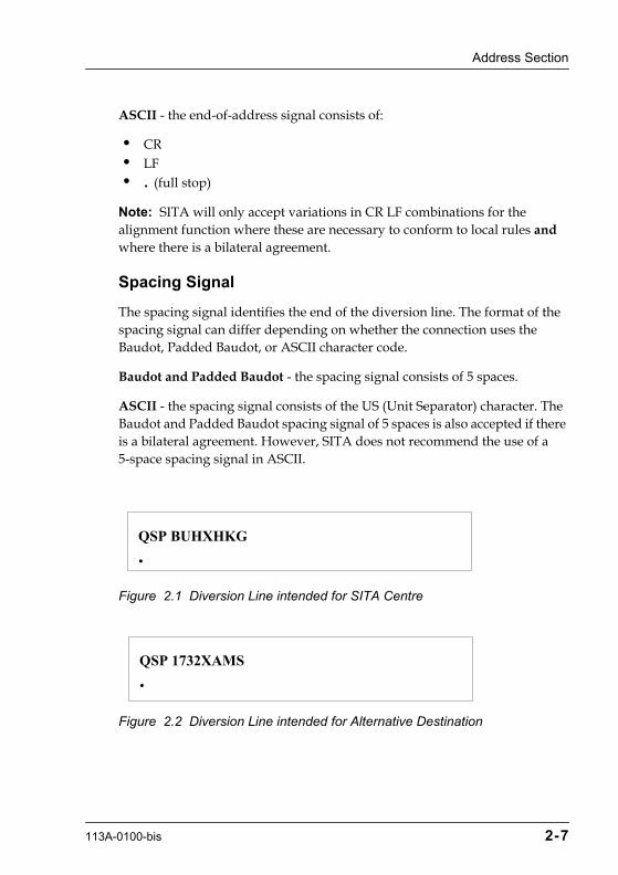
For example, if the SITA centre in Hong Kong was rerouting messages to Bucharest through the SITA centre in Vienna then the diversion line would be QSP BUHXHKG. See Figure 2.1.
Information for Alternative Destination - When the routing indicator is used because of a deviation in the SITA switching system local delivery, the routing indicator is an 8-character group composed of the following elements in the order shown:
¥ the 4-digit destination number of the original destination station ¥ the letter X ¥ the 3-character location identifier (city/airport code) of the local SITA
switching system that is rerouting the message
For example, if the destination station AMSTOBA is isolated and BA requests the local switching system (AMS) to reroute messages for that address to AMSRRSR then the routing indicator would be QSP 1732XAMS (1732 is the destination number for AMSTOBA). See Figure 2.2.
Note: There must be prior agreement between the isolated station and the chosen alternative station before messages can be rerouted.
End-of-Address Signal
The end-of-address signal differs depending on whether the connection uses the Baudot, Padded Baudot, or ASCII character code.
Baudot - the end-of-address signal consists of:
¥ CARRET ¥ LINEFEED ¥ . (full stop. Typed as FIGS M)
Padded Baudot - the end-of-address signal consists of:
¥ CARRET (Letter Mode) ¥ LINEFEED (Letter Mode) ¥ . (full stop. Typed as M in Figure Mode)
2-6 113A-0100-bis
Address Section
ASCII - the end-of-address signal consists of:
¥ CR ¥ LF ¥ . (full stop)
Note: SITA will only accept variations in CR LF combinations for the alignment function where these are necessary to conform to local rules and where there is a bilateral agreement.
Spacing Signal
The spacing signal identifies the end of the diversion line. The format of the spacing signal can differ depending on whether the connection uses the Baudot, Padded Baudot, or ASCII character code.
Baudot and Padded Baudot - the spacing signal consists of 5 spaces.
ASCII - the spacing signal consists of the US (Unit Separator) character. The Baudot and Padded Baudot spacing signal of 5 spaces is also accepted if there is a bilateral agreement. However, SITA does not recommend the use of a 5-space spacing signal in ASCII.
Figure 2.1 Diversion Line intended for SITA Centre
Figure 2.2 Diversion Line intended for Alternative Destination
QSP BUHXHKG
.
QSP 1732XAMS
.
113A-0100-bis 2-7

Chapter 2 Message Formats
Short Address Line (optional)
The short address line, also known as the supplementary address line (SAL), is used in order to avoid multiple delivery of messages when a deviation from SITA standard routing is required. When a message contains a short address line, the normal address is ignored for transmission purposes.
A message can contain multiple short address lines, however, only the first short address line is used for routing purposes.
The short address line is inserted before the normal address line.
The format of the short address line is identical to the format of the normal address line. See the section Normal Address Line (mandatory) on page 2-9. However, in a short address line there must be a spacing signal after the end-of-address signal. In Baudot and Padded Baudot, the spacing signal must consist of five (5) spaces, see Figure 2.3. In ASCII, the spacing signal is the US (unit separator) character, see Figure 2.4, although five spaces are also accepted if there is a bilateral agreement.
Figure 2.3 Short Address Line with Spacing Signal in Baudot or Padded Baudot
Figure 2.4 Short Address Line with Spacing Signal in ASCII
When a message contains a short address line, there is no restriction on the number of addressee indicators that you can have in the normal address line.
BUHRRBA BUHXHKG PARWDZZ.->->->->->
SOH BUHRRBA BUHXHKG PARWDZZ.US
2-8 113A-0100-bis

Address Section
Normal Address Line (mandatory)
The normal address line is composed of the following elements in the order shown:
¥ start-of-address signal (mandatory) ¥ priority code (optional) ¥ addressee indicator (mandatory) ¥ end-of-address signal (mandatory)
Start-of-Address Signal
The start-of-address signal differs depending on whether the connection uses the Baudot, Padded Baudot, or ASCII character code.
Baudot - the start-of-address signal consists of:
¥ CARRET ¥ LINEFEED ¥ LETTERS
Padded Baudot - the start-of-address signal consists of:
¥ CARRET (Figure Mode) ¥ LINEFEED (Figure Mode)
ASCII - the start-of-address signal consists of:
¥ CR ¥ LF ¥ SOH
Note: SITA will only accept variations in CR LF combinations for the alignment function when these are required to conform to local rules and where there is a bilateral agreement.
Priority Code
The priority code specifies which priority level applies to the message. There are four priority levels for Type B messages. Table 2.1 shows these priority levels and their associated codes.
113A-0100-bis 2-9

Chapter 2 Message Formats
Table 2.1 Priority Levels and Codes
The priority code must be followed by one space.
Note: Messages with a priority code which starts with any other letter than Q (with the exception of SS) are treated as having no priority code.
There are special requirements for confirming the delivery of Level 1 messages. See the section Additional Rules for Delivery of SS and QS Messages on page 3-17.
Addressee Indicator
The addressee indicator gives the destination to which the message must be delivered. The normal address line can contain a maximum of 32 addressee indicators in 4 address lines. This means that each address line can contain a maximum of 8 addressee indicators.
The addressee indicators must be separated by one space. The address lines must be separated by an alignment function consisting of one CR and one LF.
Level Code Usage
1 SS and QS
QC
highest priority, life and death emergency situations
highest priority, reserved for SITA troubleshooting, network emergency situations
2 QU and QX operationally urgent messages
3 QK or messages with either no priority code or any other Q priority code except those defined at levels 1, 2 and 4
normal messages
4 QD deferred, delivered after all other messages cleared
2-10 113A-0100-bis
Address Section
Note: SITA will only accept variations in CR LF combinations for the alignment function when these are required to conform to local rules and where there is a bilateral agreement.
Each addressee indicator consists of a 7-character group composed of the following elements in the order shown:
¥ the 3-character location identifier (city/airport code) ¥ the 2-character office function designator (department code) ¥ the 2-character SITA Network user designator (as defined by IATA)
Note: It is not necessary to include a space after the last indicator of an address line. However, an address line ending with a space is accepted.
Copy Indicator - If required, the originator can insert the copy indicator CPYXXXX in an address line. This indicates that the message is being sent to the addressees placed after the CPYXXXX indicator for information only.
CPYXXXX is not allowed as the first address.
CPYXXXX is counted as one addressee indicator. SITA accepts multiple copy indicators in the address line, however, some systems do not.
End-of-Address Signal
The end-of-address signal differs depending on whether the connection uses the Baudot, Padded Baudot, or ASCII character code.
Baudot - the end-of-address signal consists of:
¥ CARRET ¥ LINEFEED ¥ . (full stop. Typed as FIGS M)
Padded Baudot - the end-of-address signal consists of:
¥ CARRET (Letter Mode) ¥ LINEFEED (Letter Mode) ¥ . (full stop. Typed as M in Figure Mode)
ASCII - the end-of-address signal consists of:
113A-0100-bis 2-11
Chapter 2 Message Formats
¥ CR ¥ LF ¥ . (full stop)
Note: SITA will only accept variations in CR LF combinations for the alignment function where these are required to conform to local rules and where there is a bilateral agreement.
Figure 2.5 Address Section with Short Address Line and Normal Address Line
Origin Section
The origin section identifies the source of the message. It is composed of the following elements in the order shown:
¥ the originator indicator (mandatory) ¥ the double signature (if required) ¥ the message identity (optional)
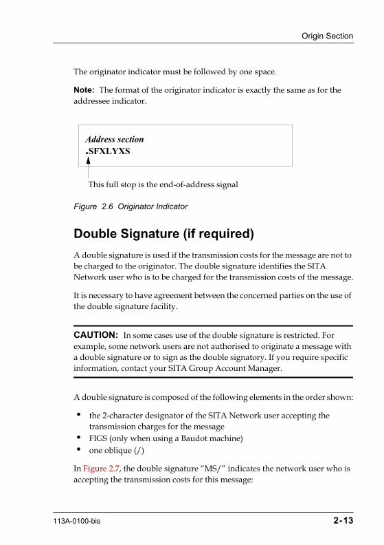
Originator Indicator (mandatory)
The originator indicator is also known as the signature. It must start immediately after the end-of-address signal. This means that the originator indicator is always preceded by a full stop (the end-of-address signal).
The originator indicator consists of a 7-character group composed of the following elements in the order shown:
¥ the 3-character location identifier (city/airport code) ¥ the 2-character office function designator (department code) ¥ the 2-character SITA Network user designator (as defined by IATA)
BUHRRBA.QD ZRHRRBA LONRRBA PARWDZZ.
2-12 113A-0100-bis
Origin Section
The originator indicator must be followed by one space.
Note: The format of the originator indicator is exactly the same as for the addressee indicator.
Figure 2.6 Originator Indicator
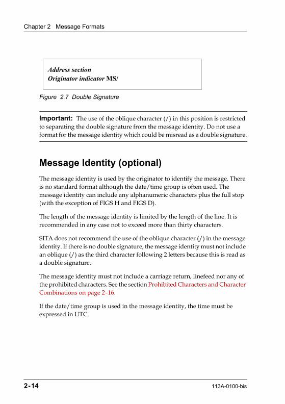
Double Signature (if required)
A double signature is used if the transmission costs for the message are not to be charged to the originator. The double signature identifies the SITA Network user who is to be charged for the transmission costs of the message.
It is necessary to have agreement between the concerned parties on the use of the double signature facility.
CAUTION: In some cases use of the double signature is restricted. For example, some network users are not authorised to originate a message with a double signature or to sign as the double signatory. If you require specific information, contact your SITA Group Account Manager.
A double signature is composed of the following elements in the order shown:
¥ the 2-character designator of the SITA Network user accepting the transmission charges for the message
¥ FIGS (only when using a Baudot machine) ¥ one oblique (/)
In Figure 2.7, the double signature ÒMS/Ó indicates the network user who is accepting the transmission costs for this message:
Address section.SFXLYXS
This full stop is the end-of-address signal
113A-0100-bis 2-13
Chapter 2 Message Formats
Figure 2.7 Double Signature
Important: The use of the oblique character (/) in this position is restricted to separating the double signature from the message identity. Do not use a format for the message identity which could be misread as a double signature.
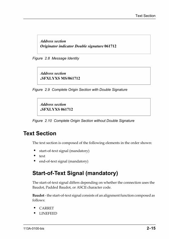
Message Identity (optional)
The message identity is used by the originator to identify the message. There is no standard format although the date/time group is often used. The message identity can include any alphanumeric characters plus the full stop (with the exception of FIGS H and FIGS D).
The length of the message identity is limited by the length of the line. It is recommended in any case not to exceed more than thirty characters.
SITA does not recommend the use of the oblique character (/) in the message identity. If there is no double signature, the message identity must not include an oblique (/) as the third character following 2 letters because this is read as a double signature.
The message identity must not include a carriage return, linefeed nor any of the prohibited characters. See the section Prohibited Characters and Character Combinations on page 2-16.
If the date/time group is used in the message identity, the time must be expressed in UTC.
Address sectionOriginator indicator MS/
2-14 113A-0100-bis
Text Section
Figure 2.8 Message Identity
Figure 2.9 Complete Origin Section with Double Signature
Figure 2.10 Complete Origin Section without Double Signature
Text Section
The text section is composed of the following elements in the order shown:
¥ start-of-text signal (mandatory) ¥ text ¥ end-of-text signal (mandatory)
Start-of-Text Signal (mandatory)
The start-of-text signal differs depending on whether the connection uses the Baudot, Padded Baudot, or ASCII character code.
Baudot - the start-of-text signal consists of an alignment function composed as follows:
¥ CARRET ¥ LINEFEED
Address sectionOriginator indicator Double signature 061712
Address section.SFXLYXS MS/061712
Address section.SFXLYXS 061712
113A-0100-bis 2-15
Chapter 2 Message Formats
Padded Baudot - the start-of-text signal consists of an alignment function composed as follows:
¥ CARRET (Letter or Figure Mode) ¥ LINEFEED (Letter or Figure Mode)
ASCII - the start-of-text signal consists of an alignment function followed by the STX character as follows:
¥ CR ¥ LF ¥ STX
Note: SITA will only accept variations in CR LF combinations for the alignment function when these are required to conform to local rules and where there is a bilateral agreement.
Text
The text of a message can be drafted in any agreed language, whether coded or not. The text must comply with the rules for acceptable messages. See the section Messages Used by Service in Chapter 1.
The text should be as brief as possible and must not contain any of the prohibited characters or character combinations. See Prohibited Characters and Character Combinations.
SITA recommends that each text line should contain a maximum of 69 characters (printed characters and spaces) and must end with an alignment function. The alignment function can be any combination of CR and LF. This line format is understood by all receiving systems. SITA places no restriction on line length.
Prohibited Characters and Character Combinations
The characters and combinations of characters specified in the following sections must never be used within the text of a Type B message.
Baudot and Padded Baudot
¥ ZCZC - start-of-message signal on some communications systems.
2-16 113A-0100-bis

Text Section
¥ NNNN - end-of-message signal on some communications systems. ¥ FIGS V - if preceded by a carriage return and a linefeed as this is the
end-of-text signal on some communications systems. ¥ FIGS H - end-of-transmission signal on some communications systems. ¥ FIGS D - ÒWHO ARE YOUÓ. ¥ LINEFEED QTA - if preceded by a carriage return and followed by the
end-of-text signal. This is recognised as the cancellation sequence by a computer system. Only use this sequence in the text if you want to cancel the message.
ASCII
The following ASCII control characters:
¥ SOH - start of heading ¥ STX - start of text ¥ EOT - end of transmission ¥ ENQ - enquiry ¥ ACK - acknowledge ¥ NAK - negative acknowledge ¥ ETB - end of transmitted block ¥ DLE - data link escape ¥ ETX - end of text ¥ SYNC - synchronous ¥ DC1 - XON (11 Hex) ¥ DC3 - XOFF (13 Hex)
Any characters or sequences that would translate into the following prohibited Baudot characters.
¥ ZCZC - start-of-message signal on some communications systems. ¥ NNNN - end-of-message signal on some communications systems. ¥ = - end-of-text signal on some communications systems. ¥ LF QTA - if preceded by a carriage return and followed by the end-of-text
signal. This is recognised as the message cancellation sequence by a computer system. Only use this sequence in the text if you want to cancel the message.
113A-0100-bis 2-17

Chapter 2 Message Formats
Indicators used in the Text
When the originator includes additional indicators in the text, such as:
¥ PDM (possible duplicate message) ¥ COR (correction message) ¥ information itself (text) ¥ COL (collation/confirmation of specific parts of the message) ¥ DUPE TO FOLLOW ¥ Sequence Indicator of Parts
These indicators must be placed in the order shown.
PDM (Possible Duplicate Message)
When it is necessary to repeat a message that has previously been transmitted, the repetition must contain the PDM indicator on a separate first text line. See Figure 2.11.
Figure 2.11 PDM Indicator
When a message is resent by a computer, the PDM indicator is added automatically.
COR (Correction Message)
When a message has been transmitted with an error in the text, this can be corrected in either of the following ways:
¥ correctly repeating the complete message ¥ sending a new message which contains information about the necessary
correction
KHIRRAF.ROMRRAF 031115PDMtext as required
2-18 113A-0100-bis

Text Section
In both cases, the COR indicator is included on a separate text line of the correction message.
COL (Collation)
The correctness of significant text parts may be confirmed by repeating them as the last element of the message text. The repetition is preceded by the COL indicator.
DUPE TO FOLLOW
This indicator is used when a message has been received corrupted but contains enough information to be transmitted onwards. The DUPE TO FOLLOW indicator notifies the addressees that the full message will be retransmitted as soon as possible.
Sequence Indicator of Parts
When a message is split by the originator before transmission, the sequence indicator of parts tells the addressees the order in which the part-messages should be read. The sequence indicator included by the originator must always appear at the end of the text section and separated from the text by one blank line. See Figure 2.12.
113A-0100-bis 2-19

Chapter 2 Message Formats
Figure 2.12 Sequence Indicator added by Originator
Adding the sequence indicator at the end of the text section avoids confusion if the message is also split during transmission by a SITA switching system. See the section Sequence Indicator of Message Parts on page 3-10.
Users of SITATEX
SITATEX includes the facility to split a message automatically before transmission. In this case, the Sequence Indicator of Parts is inserted at the beginning of the text section as described in the section Sequence Indicator of Message Parts on page 3-10.
In SITATEX 4 the part information at the beginning of the text section allows automatic re-assembly of the complete message. However, for the part information to be used in this way, the date/time group must be exactly the same in each part message. Part messages that have been split automatically by SITATEX always have the same date/time group.
KHIRRAF.ROMRRAF 031115
first part of text
PART 1 CONTINUED
KHIRRAF.ROMRRAF 031116
last part of text
PART 2 END
2-20 113A-0100-bis

Ending Section
End-of-Text Signal
The end-of-text signal differs depending on whether the connection uses the Baudot, Padded Baudot, or ASCII character code.
Baudot - the end-of-text signal consists of:
¥ CARRET ¥ LINEFEED ¥ = (Typed as FIGS V)
Padded Baudot - the end-of-text signal consists of:
¥ CARRET (Letter Mode) ¥ LINEFEED (Letter Mode) ¥ = (Typed as V in Figure Mode)
ASCII - the end-of-text signal consists of:
¥ CR ¥ LF ¥ ETX
Note: SITA will only accept variations in CR LF combinations for the alignment function where these are required to conform to local rules and where there is a bilateral agreement.
Ending Section
The ending section is connection type specific. Refer to the relevant chapter in this manual for details.
Cancelling a Partly-transmitted Message
When a partly-transmitted message is found to contain an error in the Address or Origin section, the part already transmitted must be cancelled by transmitting the following sequence:
¥ carriage return
113A-0100-bis 2-21

Chapter 2 Message Formats
¥ the sequence LINEFEED QTA repeated three times ¥ end-of-text signal and, if used, the ending
The repetition of the LINEFEED QTA sequence is used so the operator can see immediately that the message has been cancelled, for example with TTY or SITATEX. See Figure 2.13
Figure 2.13 Cancellation Sequence for Typical TTY Connection
On circuits between 2 computer systems only one QTA is required. A computer system detects the cancellation on the following sequence:
¥ LF ¥ QTA ¥ end-of-text signal
Figure 2.14 Cancellation Sequence on Circuit between Two Computer Systems
QN NCEFWXS.PARNMXS 031115ATTENTION ALL XQTA
QTAQTA
QN NCEFWXS.PARNMXS 031115ATTENTION ALL XQTA=
2-22 113A-0100-bis

Cancelling a Partly-transmitted Message
QSP ABJXPAR
.QN ABJRMRK
.
QN ABJRMRK PARTORK
. NYCRMUA RK /031545
PDMCORText.........................................Text.........................................COLDUPE TO FOLLOWPART N CONTINUED / END
connection type specific Heading
Diversion Line (if required)
Supplemental address (if required)
Start of address signal
Priority code (if any)
Addressee indicator (s)- Maximum 8 per address line- Maximum 4 address lines- Maximum 32 addressee indicators
End of address signal
Originator indicator
Double signature (if required)
Message identity
Start of text signal
Each indicator on a separateline and in this order ifmore than one used
Information itself
Each indicator on a separateline and in this order ifboth are used
End of text signal(FIGS V may appear as anothersign on page copy)
connection type specific Ending
{
{
113A-0100-bis 2-23

Chapter
3
113A-0100-bis
Transmission and Protection
This chapter describes the standards and procedures for ensuring that a Type B message is transmitted efficiently and securely over the SITA Network.
Message Acceptance
When a message is sent from a Type B terminal, it is first transmitted to its host SITA MHS. On arrival at the MHS, a message is checked for valid format, addresses, and origins. Any message that does not pass these checks is automatically returned to the service address, the terminal defined as accepting service messages for the originator. The service address can be the originator, a dedicated SITA intercept position, or any other position that has been specified in the circuit configuration.
Important: In some cases the text of the rejection message differs depending on the type of MHS that is responsible for handling the message. Therefore, the error messages listed here may not be comprehensive or an exact representation of the error messages that appear in the Type B message.
A validated message is handled in accordance with the following categories:
¥ Cancelled ¥ Format Error ¥ Invalid Origin or Destination ¥ Acceptable
3-1
Chapter 3 Transmission and Protection
Cancelled Messages
Messages that contain the QTA cancellation sequence are discarded. The cancellation sequence is composed as follows:
¥ carriage return ¥ the sequence LINEFEED QTA repeated three times ¥ end-of-text signal and, if used, the ending
The repetition of the LINEFEED QTA sequence is used so that the operator can see immediately that the message has been cancelled, for example with TTY or SITATEX.
On circuits between two computer systems, only one QTA is required. A computer system detects the cancellation on the following sequence:
¥ LF ¥ QTA ¥ end-of-text signal
If the message contains an input serial number, this is taken into account by the SITA MHS, therefore the next input message from the same origin must have the next serial number. See the section Serial Numbering on page 3-14.
Format Error
A format error is any deviation from the required SITA format, including the absence of mandatory elements. Messages that contain format errors are indicated by rejection messages. A rejection message is transmitted to the originator of a message that has been rejected if they are configured to receive such messages, otherwise the rejection is sent to the intercept position.
The rejection message has the following format:
PLS RPT YR cnnn DUE TOReason for Rejection
where ÒcÓ is the circuit number and ÒnnnÓ is the serial number, if any. See Figure 3.1.
3-2 113A-0100-bis

Format Error
Figure 3.1 Format Error Rejection Message
Check on Address Section
The message is rejected if the address line contains any of the following errors:
¥ invalid number of addresses ¥ incorrect start-of-address signal ¥ incorrect end-of-address signal ¥ other format error
Invalid Number of Addresses
If the message contains more than 8 addresses per address line or more than 69 characters per address line, the reason for rejection is given as one of the following:
¥ EXSV ADS ¥ INCOR ADS LINE
Incorrect Start-of-Address Signal
If the start-of-address signal is incorrectly received, the reason for rejection is given as one of the following:
¥ INCOR SOA ¥ INCOR ADS LINE
QU ADSXXYY.PARXMXS DDHHMM
PLS RPT YR 2123 DUE TOreason for rejectioncomplete incorrect message
113A-0100-bis 3-3

Chapter 3 Transmission and Protection
Incorrect End-of-Address Signal
If the end-of-address signal is incorrectly received or there are more than 32 addressee indicators, the reason for rejection is given as one of the following:
¥ INCOR EOA ¥ INCOR ADS LINE
Other Format Error
If there is any other error in the format of the address line, the reason for rejection is given as one of the following:
¥ GARBLED ADDRESS ¥ INCOR ADS LINE
Check on Origin Section
If there is an error in the format of the origin section, the reason for rejection is given as one of the following:
¥ NON IDEN ORIGIN ¥ INCOR SIG LINE
Missing End-of-Text/End-of-Message Signal
If the end-of-text or end-of message signal is missing and enough characters have been received for the message to be relayed to its destination as DUPE TO FOLLOW, the reason for rejection is given as one of the following:
¥ NO EOM RLA ¥ W/O EOM RLA
If the end-of text or end-of-message signal is missing and not enough characters have been received to relay the message to its destination, the reason for rejection is given as one of the following:
¥ NO EOM NOT RLA ¥ W/O EOM NOT RLA
3-4 113A-0100-bis
Format Error
Miscellaneous
There are a number of other format errors that result in a message being rejected. These miscellaneous errors are as follows:
¥ message interrupted during reception ¥ data characters between messages ¥ excessive number of identical characters ¥ too many characters in message ¥ multiple errors
Message Interrupted During Reception
If the message is interrupted during reception and enough characters are received to relay the message to its destination as DUPE TO FOLLOW, the reason for rejection is given as one of the following:
¥ LINE IDLE RLA ¥ LINE OPEN RLA ¥ NO EOM RLA CCT ERR
If the message is interrupted during reception and not enough characters are received to relay the message to its destination, the reason for rejection is given as one of the following:
¥ LINE IDLE NOT RLA ¥ LINE OPEN NOT RLA ¥ NO EOM NOT RLA CCT ERR
Data Characters between Messages
If data characters are received that cannot be considered as part of a message, for example there is no start-of-message or start-of-address signal, the reason for rejection is as follows:
¥ SPURIOUS
113A-0100-bis 3-5
Chapter 3 Transmission and Protection
Excessive Number of Identical Characters
If the message contains more than 120 consecutive identical characters the reason for rejection is as follows:
¥ STUCK TAPE
Note: Some systems detect STUCK TAPE on fewer characters, for example 80 consecutive identical characters.
Too Many Characters
If the message contains more than 3840 characters, the reason for rejection is given as one of the following:
¥ OVER LENGTH ¥ TOO LONG
Multiple Errors
If the message contains more than one format error the reason for rejection is as follows:
¥ MULTI ERRORS
Invalid Origin or Destination
Once the message format has been validated, the origin and destination addresses are checked against the system tables. A message can be rejected for the following reasons:
¥ unauthorised input ¥ unknown destination address ¥ routing error
3-6 113A-0100-bis
Invalid Origin or Destination
Unauthorised Input
In general, all SITA members are authorised to input messages to the network. Non-members are authorised under specific agreements which may limit their authorisation. In addition, there is an optional restriction to limit use of an input circuit to a particular originator indicator (signature). Details of authorisation are held in local system tables for each MHS.
If the originator indicator is not recognised as an authorised SITA Network user, the message is rejected. The reason for rejection is given as one of the following:
¥ INPUT NOT AUTHORISED ¥ NSMA IN ADS LINE ¥ UNAUTHOR SIGN
For more information on authorisation to use the SITA Network, contact Marketing/Customer Support.
Unknown Destination Address
If an addressee indicator is not valid according to the system tables, the message is rejected for that address. An address is considered unknown for the following reasons:
¥ code unknown ¥ no delivery point ¥ out of use
Code Unknown
If any of the codes used in the address are not defined in the ATA/IATA Airline Coding Directory, the message is relayed to valid destinations with a short address line. An error message is returned to the originator with the following information:
¥ address UNKNOWN / OTHER DELIVERED AS FOLLOW:priority code and addresses delivered to
113A-0100-bis 3-7

Chapter 3 Transmission and Protection
Figure 3.2 Unknown Address Message
No Delivery Point
If the city code is valid but there is no delivery point defined for the address, the message is relayed to valid destinations with a short address line. An error message is returned to the originator with the following information:
¥ NO DISPOSAL FOR address OTHER DELIVERED AS FOLLOWpriority code and addresses delivered to
Figure 3.3 No Disposal Message
Out of Use
A mnemonic address can be configured temporarily in the routing database as being out of use. If a message contains such an address, it is returned to the originator with the following information:
QU FRAQZXS.PARNGXS 111321XARXXXX UNKNOWN / OTHER DELIVERED AS FOLLOW:
QU PARQSXS PARVRXS.
QU PARQZXS.PARNGXS 111321NO DISPOSAL FOR PARXXXX OTHER DELIVERED AS FOLLOW
QU PARQSXS PARVRXS.
3-8 113A-0100-bis

Invalid Origin or Destination
¥ NO ACTION ADSaddress configured as no actionoriginal message
Figure 3.4 No Action Address Message
Routing Errors
A message received for which the receiving system has no routing responsibility is handled as follows:
1. For a single-address delivery message, the message must be accepted and relayed to its destination unless there are any local procedures in force that prevent delivery to the specified destination address. A copy of the message is sent to the information position in the MHS for information.
If local procedures prevent delivery, the message is returned in the form of a service message with one of the following error messages:
¥ MSR
¥ PLS RPT YR cnnn DUE TO MSR SINGLE ADS
2. For a multiple-address message, when none of the addresses are within the routing responsibility of the receiving system, the message is sent to the intercept position, which then manually returns the message to the station from which it was received. The message is returned in the form of a service message with one of the following error messages:
¥ MSR
¥ PLS RPT YR cnnn DUE TO MSR MULTI ADS
QU CCDDAA.PARXMXS DDHHMMPLS RPT YR CNNNN DUE TO NO ACTION ADSDDDEEFFfollowed by the original message
113A-0100-bis 3-9

Chapter 3 Transmission and Protection
Important: The start-of-message signal (ZCZC) must never be returned with the misrouted message. The message is returned from the start-of-address signal to the end-of-message signal.
3. The system receiving a misrouting service message must reroute the message correctly via the circuits prescribed in the applicable routing instructions. The indicator PDM must be added to the rerouted message as the first text line. See PDM (Possible Duplicate Message) in Chapter 2.
A routing error detected by the transmitting station while the message is in the course of transmission must be corrected by stopping transmission, cancelling the transmitted part, and transmitting the message over the correct circuit.
Messages Accepted by the Service
To be acceptable, a message must have passed the following checks:
1. Message format
2. Validity of origin and destination addresses
If the format, origin, and addresses are all valid, the message is transmitted to its destination.
Messages containing more than 3500 characters may be split for transmission over the SITA Network. See Sequence Indicator of Message Parts.
Sequence Indicator of Message Parts
For technical reasons, a message that contains more than 3500 characters may have to be split into smaller parts. The text is split into as many part-messages as required for transmission as separate messages.
Each of the part-messages must contain the same addressee indicators and the same originator indicator, and will be labelled accordingly.
3-10 113A-0100-bis

Sequence Indicator of Message Parts
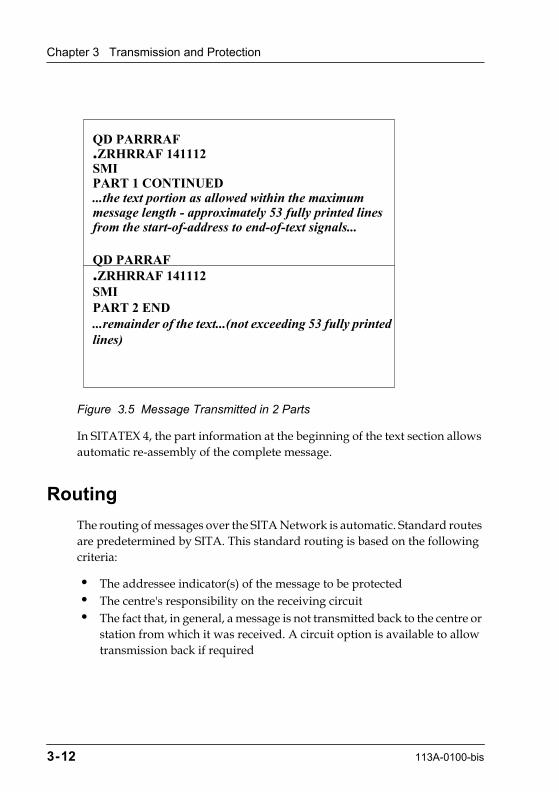
The sequence of the part-messages is shown at the beginning of the text section by a sequence indicator. For example, if the original message required transmission in three parts, the sequence indicators for the three separate messages would be as follows:
¥ PART 1 CONTINUED
for the first part-message
¥ PART 2 CONTINUED
for the second part-message
¥ PART 3 END
for the last part-message
If the message contains a Standard Message Indicator (SMI), for example PDM, the sequence indicator is included on the line following the SMI.
Note: A sequence indicator of message parts added by the originator must appear at the end of the text section to avoid possible confusion with a sequence indicator added during transmission by a SITA message handling system. See Sequence Indicator of Parts in Chapter 2.
Figure 3.5 gives an example of a message with a total length exceeding 3500 characters that has been split into two parts for transmission, where the original message contained an SMI.
113A-0100-bis 3-11
Chapter 3 Transmission and Protection
Figure 3.5 Message Transmitted in 2 Parts
In SITATEX 4, the part information at the beginning of the text section allows automatic re-assembly of the complete message.
Routing
The routing of messages over the SITA Network is automatic. Standard routes are predetermined by SITA. This standard routing is based on the following criteria:
¥ The addressee indicator(s) of the message to be protected ¥ The centre's responsibility on the receiving circuit ¥ The fact that, in general, a message is not transmitted back to the centre or
station from which it was received. A circuit option is available to allow transmission back if required
QD PARRRAF.ZRHRRAF 141112SMIPART 1 CONTINUED...the text portion as allowed within the maximum message length - approximately 53 fully printed lines from the start-of-address to end-of-text signals...
QD PARRAF.ZRHRRAF 141112SMIPART 2 END...remainder of the text...(not exceeding 53 fully printed lines)
3-12 113A-0100-bis

Order of Transmission
The Role of the SITA MHS
Each SITA MHS is responsible for accepting, checking, storing, and routing messages received from the equipment and services which come under its control. For example, one type of MHS is responsible for the Teleprinters, Telexes, and PCs that make up the Low Level Network. A different type of MHS is responsible for the concentration of ACS traffic by means of a medium speed network and also acts as the SITATEX server.
There are a number of options for defining how a Type B message is handled when it arrives at its host MHS. These options are defined at the level of the circuit or station.
Once a message has been accepted, the MHS envelopes the message for routing within the SITA Network.
On reception, a message is stored for transmission according to its priority code. After it is transmitted, the message is stored again by the MHS, this time for retrieval. A message can be retrieved for up to 7 complete days after the transmission date. For example, if a message is transmitted at midday on Monday, it is retrievable up to midday on the following Monday. After seven days, the stored message is deleted.
Order of Transmission
The order of transmission of messages on a given circuit is determined by their priority codes as follows:
1. Level 1 - Messages with priority codes SS, QS, or QC. These are handled before all other messages.
2. Level 2 - Messages with priority codes QU or QX. These are handled before messages of levels 3 and 4.
3. Level 3 - Messages with a QK code, a Q code other than QS, QC, QU, QX, and QD, or no priority code. These are handled before messages of level 4.
Note: Messages with a priority code which starts with any other letter than Q (with the exception of SS) are treated as having no priority code.
113A-0100-bis 3-13
Chapter 3 Transmission and Protection
4. Level 4 - Messages with priority code QD. These are deferred until no messages of levels 1, 2, or 3 are waiting for transmission. However, level 4 messages are delivered not later than the morning following the day they were handed in for transmission.
Note: In general, within a given level, the order of transmission is determined by the order of receipt, that is first in first out (FIFO). However, due to network structure and technical constraints, it is possible for messages of the same priority to arrive in a different order.
TrafÞc Protection and Continuity Control
Protection of messages is assumed by the protocol used. Type B is always protected, the type of protection depends on the protocol.
Type B messages are fully protected inside the SITA Network. In addition, input and output are protected by various methods, for example serial numbering (freewheeling circuits) and an end-to-end protocol called BATAP (Type B Application to Application Protocol).
Serial Numbering
Serial numbering is used on point-to-point (TTY, MSL, and LSC) circuits. Each message must be identifiable by its serial number within the sequence of messages transmitted. This means that once a serial number has been assigned to a message which is either partly or completely transmitted, that serial number is not re-assigned.
Where practical, the serial number is included in the heading or communications control information of each individual message.
The serial number is composed of 3 digits from 001 to 000 (1000). If the serial number reaches 000 then the numbering recycles to 001 for the next message.
From SITA to Network User
At 00.00 hours UTC the serial number is set to 001 and the SITA MHS generates a midnight continuity check.
3-14 113A-0100-bis

Traffic Protection and Continuity Control
The SITA MHS will also generate a continuity check when no message is received for 30 minutes, if this option has been selected by the user. See the section Continuity Check generated by SITA MHS on page 3-16.
If a message is received with a serial number out of sequence or without a serial number, the MHS takes the following action:
1. Handles the message normally
2. Sends a serial number error message to the originator and to the information position in the operations room
The text of the serial number error message has the following format:
EXP expected serial number, preceded by circuit number if requiredRCV serial number received, preceded by circuit number if required or NO SRL NR if the serial number was missing
Figure 3.6 gives an example of a serial number error message. The last 3 digits are the serial number. The first digit is the circuit number; this is always 0 for single circuit connections.
Figure 3.6 Serial Number Error Message
Periodic Continuity Check
A SITA MHS will generate a periodic continuity check only if the option has been implemented. The default option is no continuity check.
A continuity check can be initiated and inhibited either by the user or the SITA MHS.
QU AMSTOLH.AMSXMXS 100900EXP 0008RCV 0003=
113A-0100-bis 3-15
Chapter 3 Transmission and Protection
Continuity Check generated by SITA MHS
If the continuity check option has been implemented, the SITA MHS checks the serial numbers last transmitted and last received on all circuits at thirty minute intervals, at H+00 and H+30.
If, on a given circuit, between the preceding check and the one being made, the serial numbers have advanced on reception as well as on transmission, the MHS takes no further action.
If, on a given circuit, between the preceding check and the one being made, the serial numbers have not advanced on reception or on transmission or on both, the MHS sends a status message to the user.
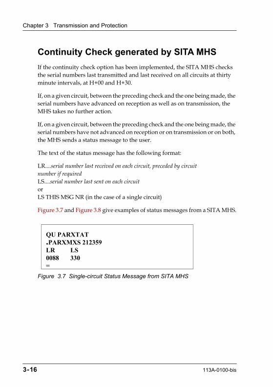
The text of the status message has the following format:
LR....serial number last received on each circuit, preceded by circuitnumber if requiredLS....serial number last sent on each circuitorLS THIS MSG NR (in the case of a single circuit)
Figure 3.7 and Figure 3.8 give examples of status messages from a SITA MHS.
Figure 3.7 Single-circuit Status Message from SITA MHS
QU PARXTAT.PARXMXS 212359LR LS0088 330=
3-16 113A-0100-bis

Additional Rules for Delivery of SS and QS Messages
Figure 3.8 Multi-circuit Status Message from SITA MHS
Additional Rules for Delivery of SS and QS Mes-sages
The following additional rules apply to delivery of SS and QS messages:
1. For each individual SS or QS message delivered, confirmation and exact time of receipt must be obtained from the addressee.
2. If confirmation and exact time of receipt are not received within ten minutes, the station of delivery must inform, by telephone, the person(s) named as being responsible for reception of SS and QS messages.
3. The local SITA Network user representative is responsible for supplying the station with any relevant information, for establishing a list of the persons responsible for receipt of SS and QS messages, and for keeping the list up-to-date.
QU PARTOLH.PARXMXS 212359LR LS1806 9212730 789=
113A-0100-bis 3-17
Chapter
4
113A-010-bis
Machine-readable Messages
This chapter explains the machine-readable messages that can be sent by a user to SITA. Machine-readable messages contain commands that are carried out automatically by a computer system. The messages are divided into two categories as follows:
¥ messages to a SITA MHS that contain message handling commands ¥ messages to a SITA service that contain commands specific to that service
Within each category, the information is arranged in alphabetical order of the message text. The following information is given for each message:
¥ purpose ¥ example ¥ response ¥ restrictions (if any)
Service Messages to a SITA MHS
This type of machine-readable message must be addressed to the SITA MHS which must act on the command contained in the message. The addressee indicator must be composed of the following elements in the order shown:
¥ The 3-character location identifier of the MHS. For example, PAR.
¥ The office function designator XM. ¥ The airline/organisation designator XS.
Note: XMXS is used only for machine-readable messages.
The address section can include additional addresses.
4-1
Chapter 4 Machine-readable Messages
The command to the MHS must appear within 200 characters of the start-of-address signal. See the section Unrecognisable Command on page 4-2.
Additional information, for example for tracking purposes, can be added by the user starting on the line following the command. This is not read as part of the command.
Unacceptable Messages
A machine-readable service message can be rejected for the following reasons:
¥ unauthorised user ¥ unrecognisable command
Unauthorised User
If the network user is not authorised to use service messages, the message is rejected as illegal. The reason for rejection is given as one of the following:
¥ ILLEGAL ¥ YR cnnn RETURNED DUE TO ILLEGAL SVC MESSAGE
Where 'c' is the circuit number and 'nnn' is the serial number, if any.
Unrecognisable Command
If the machine-readable message is unrecognisable or the parameters provided in the request fields are incorrect or missing, the message is returned to the originator. The reason for rejection is given as one of the following:
¥ ILLEGAL ¥ PLS RPT YR cnnn DUE TO INCORRECT SVC MESSAGE
Where 'c' is the circuit number and 'nnn' is the serial number, if any.
BACKLOG
This message is sent to the local SITA MHS by the network user to request information on the number of messages waiting to be delivered to them.
4-2 113A-010-bis

Service Messages to a SITA MHS
Figure 4.1 BACKLOG Service Message
This example requests information on the number of messages waiting to be delivered to the destination PARNMXS.
Response
The MHS replies by sending a Backlog Report that shows the number of messages of each priority level waiting to be delivered.
Figure 4.2 BACKLOG Report
Restrictions
BACKLOG is not available to Telex or MSL users.
CONT OFF
This message is used to suspend the continuity check carried out by the local SITA MHS for the circuit on which the message is received.See also CONT ON.
QU LONXMXS.PARNMXS 171418BACKLOG=
QU PARNMXS.LONXMXS 171417BACKLOGQC 0000QU 0000QN 0004QD 0006
113A-010-bis 4-3
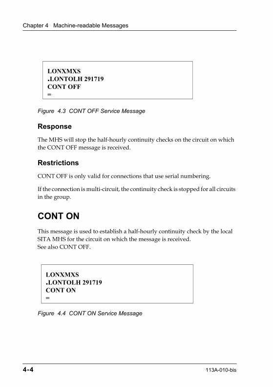
Chapter 4 Machine-readable Messages
Figure 4.3 CONT OFF Service Message
Response
The MHS will stop the half-hourly continuity checks on the circuit on which the CONT OFF message is received.
Restrictions
CONT OFF is only valid for connections that use serial numbering.
If the connection is multi-circuit, the continuity check is stopped for all circuits in the group.
CONT ON
This message is used to establish a half-hourly continuity check by the local SITA MHS for the circuit on which the message is received. See also CONT OFF.
Figure 4.4 CONT ON Service Message
LONXMXS.LONTOLH 291719CONT OFF=
LONXMXS.LONTOLH 291719CONT ON=
4-4 113A-010-bis

Service Messages to a SITA MHS
Response
The MHS will start half-hourly continuity checks on the circuit on which the CONT ON message is received.
Restrictions
CONT ON is only valid for connections that use serial numbering.
If the connection is multi-circuit, the continuity check is implemented for all circuits in the group.
GA
This message is used to notify a computer centre that transmission can resume on a circuit that has been temporarily out of service. See also STOP, as GA is normally used after a circuit has been deactivated using STOP.
The format of the text section is as follows:
GA circuit number (if required)
Figure 4.5 gives an example of a GA service message for a single-circuit or for all circuits of a multi-circuit connection and Figure 4.6 gives an example of a GA service message for a specific circuit of a multi-circuit connection, in this case circuit number 3.
Figure 4.5 GA Service Message for a Single-Circuit or for All Circuits
QU PARXMXS.ISTXTXS 131123GA=
113A-010-bis 4-5
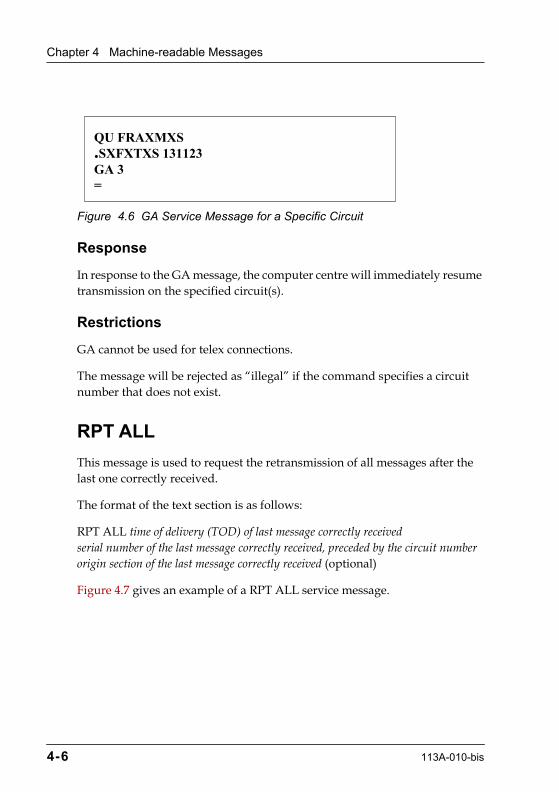
Chapter 4 Machine-readable Messages
Figure 4.6 GA Service Message for a Specific Circuit
Response
In response to the GA message, the computer centre will immediately resume transmission on the specified circuit(s).
Restrictions
GA cannot be used for telex connections.
The message will be rejected as ÒillegalÓ if the command specifies a circuit number that does not exist.
RPT ALL
This message is used to request the retransmission of all messages after the last one correctly received.
The format of the text section is as follows:
RPT ALL time of delivery (TOD) of last message correctly receivedserial number of the last message correctly received, preceded by the circuit numberorigin section of the last message correctly received (optional)
Figure 4.7 gives an example of a RPT ALL service message.
QU FRAXMXS.SXFXTXS 131123GA 3=
4-6 113A-010-bis

Service Messages to a SITA MHS
Figure 4.7 RPT ALL Service Message with TOD
This example requests the retransmission of all messages after the message with time of delivery 261930 (7.30 p.m. on the 26th) and serial number 652. The connection is single-circuit, therefore the circuit number is 0.
Response
If the RPT ALL is for the same day, the SITA MHS will retransmit all messages originally transmitted between the message specified and the last message sent at the time the RPT ALL message was received.
If the RPT ALL is for a previous day, the MHS will retransmit all messages originally transmitted between the message specified and midnight of the specified day.
Restrictions
RPT ALL is not valid for Telex, ACS, or Synchronous SITATEX correspondents.
A maximum of 50 messages will be retransmitted.
A single RPT ALL can only repeat messages for the same day, the TOD range must not cross midnight.
A single RPT ALL cannot cover a series of messages within which the serial number was reset to zero. Two RPT ALL messages would have to be used.
RPT BTN (serial number)
This message is used to request a retransmission of all messages between two messages correctly received.
AMSXMXS.AMSTOIB 271245RPT ALL 2619300652=
113A-010-bis 4-7

Chapter 4 Machine-readable Messages
The format of the text section is as follows:
RPT BTN time of delivery (TOD) of last correctly received messageserial numbers of the two messages correctly received, preceded by the circuit numberorigin sections of the two messages correctly received (optional)
Figure 4.8 gives an example of a RPT BTN service message.
Figure 4.8 RPT BTN Service Message using Serial Numbers
This example requests retransmission of the messages with serial numbers between 028 and 040 that were received on circuit number 1 of a multi-circuit connection. The time of delivery of the last correctly received message is 270930 (9.30 a.m. on the 27th).
Note: The serial numbers specified are exclusive. This example will result in the retransmission of the messages numbered from 29 to 39.
Response
The SITA MHS will retransmit all messages with a serial number between the two message serial numbers specified.
Restrictions
RPT BTN using serial numbers is not valid for Telex, ACS, or Synchronous SITATEX correspondents.
RPT BTN can only be used if the number of messages to be retransmitted does not exceed 50.
A single RPT BTN (serial numbers) can only repeat messages for the same day.
FRAXMXS.FRAXQSR 271230RPT BTN 2709301028 040=
4-8 113A-010-bis
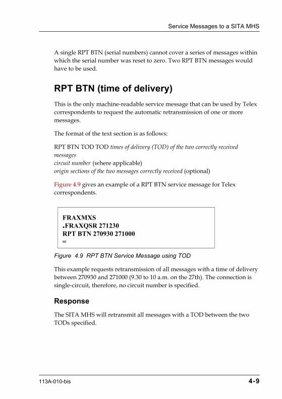
Service Messages to a SITA MHS
A single RPT BTN (serial numbers) cannot cover a series of messages within which the serial number was reset to zero. Two RPT BTN messages would have to be used.
RPT BTN (time of delivery)
This is the only machine-readable service message that can be used by Telex correspondents to request the automatic retransmission of one or more messages.
The format of the text section is as follows:
RPT BTN TOD TOD times of delivery (TOD) of the two correctly receivedmessagescircuit number (where applicable)origin sections of the two messages correctly received (optional)
Figure 4.9 gives an example of a RPT BTN service message for Telex correspondents.
Figure 4.9 RPT BTN Service Message using TOD
This example requests retransmission of all messages with a time of delivery between 270930 and 271000 (9.30 to 10 a.m. on the 27th). The connection is single-circuit, therefore, no circuit number is specified.
Response
The SITA MHS will retransmit all messages with a TOD between the two TODs specified.
FRAXMXS.FRAXQSR 271230RPT BTN 270930 271000=
113A-010-bis 4-9
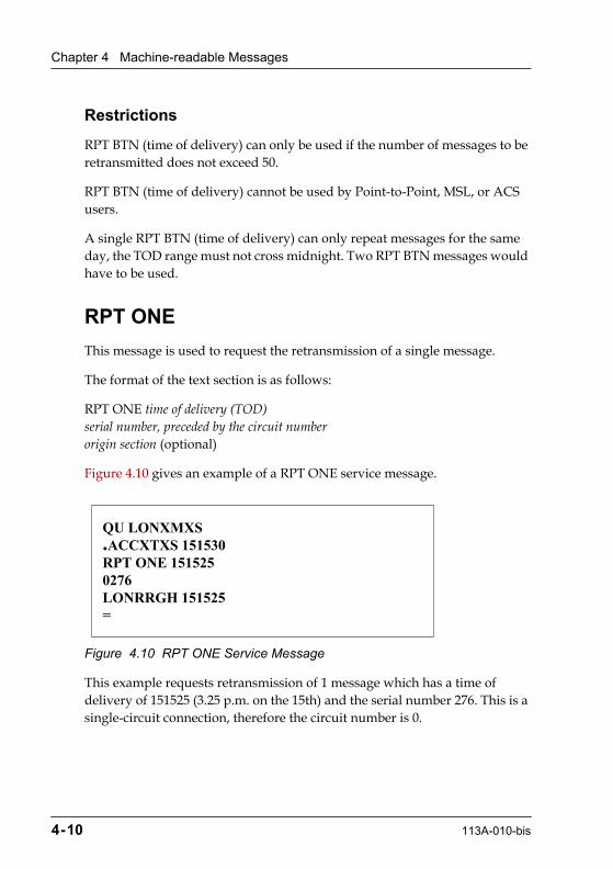
Chapter 4 Machine-readable Messages
Restrictions
RPT BTN (time of delivery) can only be used if the number of messages to be retransmitted does not exceed 50.
RPT BTN (time of delivery) cannot be used by Point-to-Point, MSL, or ACS users.
A single RPT BTN (time of delivery) can only repeat messages for the same day, the TOD range must not cross midnight. Two RPT BTN messages would have to be used.
RPT ONE
This message is used to request the retransmission of a single message.
The format of the text section is as follows:
RPT ONE time of delivery (TOD)serial number, preceded by the circuit numberorigin section (optional)
Figure 4.10 gives an example of a RPT ONE service message.
Figure 4.10 RPT ONE Service Message
This example requests retransmission of 1 message which has a time of delivery of 151525 (3.25 p.m. on the 15th) and the serial number 276. This is a single-circuit connection, therefore the circuit number is 0.
QU LONXMXS.ACCXTXS 151530RPT ONE 1515250276LONRRGH 151525=
4-10 113A-010-bis
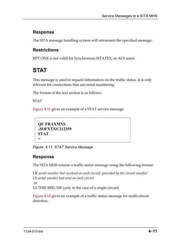
Service Messages to a SITA MHS
Response
The SITA message handling system will retransmit the specified message.
Restrictions
RPT ONE is not valid for Synchronous SITATEX, or ACS users.
STAT
This message is used to request information on the traffic status. It is only relevant for connections that use serial numbering.
The format of the text section is as follows:
STAT
Figure 4.11 gives an example of a STAT service message.
Figure 4.11 STAT Service Message
Response
The SITA MHS returns a traffic status message using the following format:
LR serial number last received on each circuit, preceded by the circuit numberLS serial number last sent on each circuit orLS THIS MSG NR (only in the case of a single-circuit)
Figure 4.12 gives an example of a traffic status message for multi-circuit direction.
QU FRAXMXS.SOFXTXS 212359STAT=
113A-010-bis 4-11

Chapter 4 Machine-readable Messages
Figure 4.12 Traffic Status Message for Multi-circuit Direction
This example shows that for circuit 1, the last message received was number 806 and the last message sent was number 921. For circuit 2, the last message received was number 730 and the last message sent was number 789.
For a single-circuit direction, the circuit number is always 0.
Restrictions
STAT is not valid for Telex, Synchronous SITATEX, or ACS users.
STOP
Used to request a computer to suspend transmission on all circuits or on a specified circuit. See also GA, which is used to restart transmission.
The format of the text section is as follows:
STOP circuit number (if required)
Figure 4.13 gives an example of a STOP message for a specified circuit, in this case circuit number 3.
Figure 4.13 STOP Service Message for a Specified Circuit
QU PARTOLH.PARXMXS 212359 LR LS1806 9212730 789=
QU PARXMXS.ISTXTXS 131117STOP 3=
4-12 113A-010-bis
Messages to SITA Services
Response
The SITA MHS will stop transmission on the specified circuit.
Restrictions
STOP is not applicable to Telex users.
Messages to SITA Services
This type of machine-readable message contains commands relating to a particular SITA service. In general, one address is defined for each service. The exception is RTX, which currently uses a specific SITA centre in each country where the service is available.
For all SITA services, you can include additional Type B addresses in the address line of the message. The message is sent to the service for processing and is also sent to the additional Type B destinations as a normal Type B message.
The command to the service must appear within 200 characters of the start-of-address signal. Otherwise, depending on the service, the message is either rejected or discarded.
Each of these services is explained in more detail later in this manual.
FAX
This message is used to send a message to up to sixteen fax machine destinations. Figure 4.14 gives an example of a FAX message.
113A-010-bis 4-13

Chapter 4 Machine-readable Messages
Figure 4.14 FAX Message
Response
The FAX service delivers the fax and returns a delivery notification to the originator.
Restrictions
The message must be addressed to HDQFAXS, the FAX server.
FAX is a one-way service. Type B messages can be sent to fax machines but not received from them.
GPS DIRECTORY REQUEST
This message is used to request an up-to-date list of the telephone numbers for SITATEX Gateway Processor Systems (GPS).
Figure 4.15 gives an example of a GPS Directory Request message.
Figure 4.15 GPS Directory Request
QN HDQFAXS.PARRBXSFAX 02306123456 3392966400 3155414181
HEADER: TO WHOM IT MAY CONCERNtext of the message
QU PARNJXS.XXXYYZZGPS DIRECTORY REQUEST
4-14 113A-010-bis

Messages to SITA Services
Response
The GPS directory service returns a SITATEX message containing the telephone numbers of all SITATEX Gateway Processor Systems and the associated SITA Help Desks.
Restrictions
The message must be addressed to PARNJXS, the GPS directory service.
ROUT (address)
This command is used to request details of the routing for a specified Type B address. Figure 4.16 gives an example of a ROUT message.
Figure 4.16 ROUT Message
Note: An extended version of the ROUT command is available to SITA Operations staff.
Response
An acknowledgement message is returned giving the routing information for the specified address. Figure 4.17 shows an example acknowledgement.
QN HDQXMXS.PARXXZZ 123456ROUT PARYYZZ
113A-010-bis 4-15

Chapter 4 Machine-readable Messages
Figure 4.17 Acknowledgement of ROUT Message
The information in the acknowledgement message is given under the following column headings:
Note: When the ROUT command is sent from a SITA address, the acknowledgement contains additional information on the internal SITA Network connections.
If the city code is unknown, the reply is as follows:
CTR The SITA MHS to which the circuit shown under SVC ADD isconnected.
ODN The circuit Output Destination Number or Port Identifier (PID).
SVC ADD The circuit name/service address on which the routing addressshown under R/I is delivered.
TYPE The type of connection/service, for example: STX for aSITATEX connection or TLX for a Telex connection.
R/I The routing address for which the information was requested.
QN PARXS7X.HDQXMXS 123457ACK ROUT PARXS7XPARIS FRANCE
CTR ODN SVC ADD TYPE R/I----- ----- -------- ----- --------H-ATL 011123 CAIXXXS P1124 PARXS7XH-ATL 002211 QXBBAXS STX PARXX7XH-CAI 0330 FTYXTXS ACS/ PARXS7XH-CAI 1234 QXBAJXS TBC/T PARXS7X
4-16 113A-010-bis
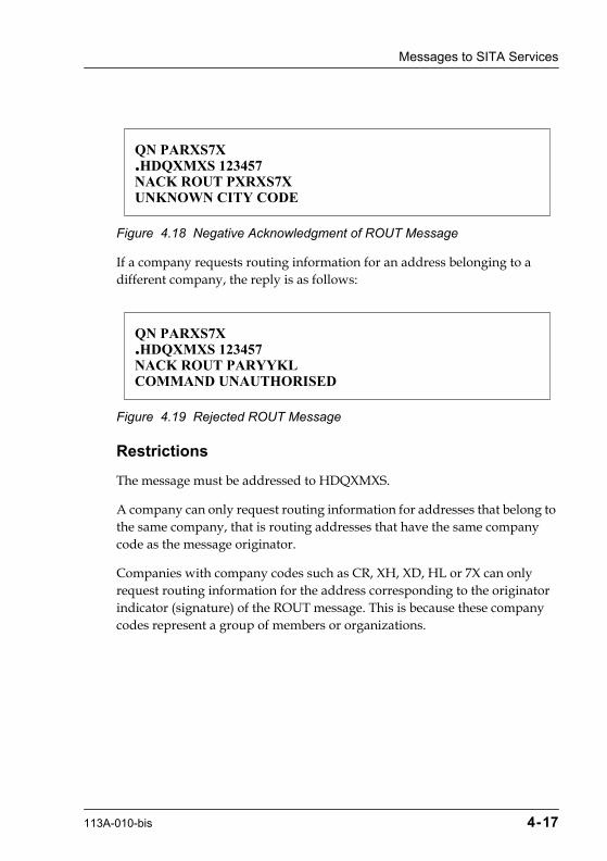
Messages to SITA Services
Figure 4.18 Negative Acknowledgment of ROUT Message
If a company requests routing information for an address belonging to a different company, the reply is as follows:
Figure 4.19 Rejected ROUT Message
Restrictions
The message must be addressed to HDQXMXS.
A company can only request routing information for addresses that belong to the same company, that is routing addresses that have the same company code as the message originator.
Companies with company codes such as CR, XH, XD, HL or 7X can only request routing information for the address corresponding to the originator indicator (signature) of the ROUT message. This is because these company codes represent a group of members or organizations.
QN PARXS7X.HDQXMXS 123457NACK ROUT PXRXS7XUNKNOWN CITY CODE
QN PARXS7X.HDQXMXS 123457NACK ROUT PARYYKLCOMMAND UNAUTHORISED
113A-010-bis 4-17

Chapter 4 Machine-readable Messages
RTB
This message is used to send commands to the RTB server, which controls the SITA broadcast service. There are a number of RTB commands that allow the user to set up and maintain lists of addresses and to broadcast a message over the SITA Network, the AFTN, and to fax and telex destinations. Figure 4.20 gives an example of an RTB message.
Figure 4.20 RTB Message
Response
The RTB server will process the command and return confirmation to the originator address (signature).
Restrictions
The originator indicator must be identified as an authorised RTB user. This can be either a registered RTB user or a user with the same company code as a registered user.
The message must be addressed to HDQXMXS, the RTB server.
RTX (telex number)
This message is used to send a message to a commercial Telex destination by means of the SITA RTX service. Figure 4.21 gives an example of an RTX message for telex numbers.
QN HDQXMXS.PARNMXSRTB XMIT LIST1
text of the message
4-18 113A-010-bis

Messages to SITA Services
Figure 4.21 RTX Message
Response
RTX delivers a Telex to the specified telex destination.
Restrictions
A message can be sent to only one Telex number at a time.
An RTX message must be addressed to only one RTX service centre for action.
The length of the dialling code must be in the range configured for the RTX server being addressed, otherwise the message is rejected as Òinvalid dial codeÓ.
A Telex user is not allowed to transmit RTX messages.
RTX (city)
This message is used to request either one or all RTX Service Centre addresses from the Main Control System (MCS) in Atlanta. The variable city allows you to request the RTX Service Centre address for a specific 3-character location code. Figure 4.22 gives an example of an RTX message requesting a service centre address.
QN PARXMXS.PARRBXSRTX 12345678
text of the message
113A-010-bis 4-19
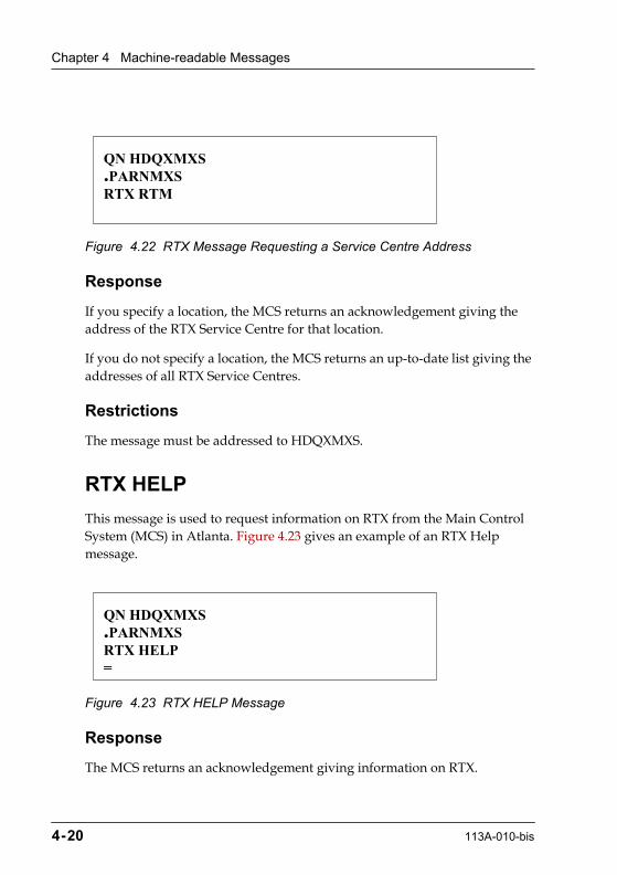
Chapter 4 Machine-readable Messages
Figure 4.22 RTX Message Requesting a Service Centre Address
Response
If you specify a location, the MCS returns an acknowledgement giving the address of the RTX Service Centre for that location.
If you do not specify a location, the MCS returns an up-to-date list giving the addresses of all RTX Service Centres.
Restrictions
The message must be addressed to HDQXMXS.
RTX HELP
This message is used to request information on RTX from the Main Control System (MCS) in Atlanta. Figure 4.23 gives an example of an RTX Help message.
Figure 4.23 RTX HELP Message
Response
The MCS returns an acknowledgement giving information on RTX.
QN HDQXMXS.PARNMXSRTX RTM
QN HDQXMXS.PARNMXSRTX HELP=
4-20 113A-010-bis
Messages to SITA Services
Restrictions
The message must be addressed to HDQXMXS.
113A-010-bis 4-21

Chapter
5
113A-0100-bis
Gateways
Gateways are a combination of hardware and software that fit two kinds of networks together. This chapter explains how messages are transferred to and from the following telecommunications systems:
¥ Aeronautical Fixed Telecommunications Network (AFTN) ¥ SMTP and X.400 service (GMS X.400)
AFTN (Aeronautical Fixed Telecommunications Network)
The methods of transferring messages between the SITA Network and the AFTN allow a great deal of flexibility. Although the two networks use different coding systems for addresses, all the codes are translatable in both directions.
Where the local AFTN station does not accept the procedures laid down in the following sections, local arrangements must be made to handle the traffic exchanged between the AFTN and the SITA Network.
The AFTN is a low speed network so the volume of traffic is always limited. The SITA Network user must make an individual arrangement with the AFTN concerning this aspect.
Message Transfer from SITA Network to AFTN
An AFTN circuit is identified as an option at circuit level. There are two ways of sending messages from the SITA Network to the AFTN, as follows:
5-1

Chapter 5 Gateways
¥ Message composed in AFTN format and addressed to SITA location YFXS. This method is recommended for messages to AFTN services which will be handled by a computer.
¥ Message composed in SITA format and SITA address translated in order to build an AFTN address.
Message Composed in AFTN Format
When it is known that a message will be transferred to the AFTN, the message is composed as follows:
¥ header in SITA Type B format ¥ complete message in AFTN format
For details about the AFTN message format, refer to Aeronautical Telecommunications, Annex 10 to the Convention of Civil Aviation, Volume II, Fourth Edition, April 1985.
The address in the SITA header must be composed as follows:
¥ the 3-character location code ¥ the office function designator YF ¥ the airline/organisation designator XS
The combination YFXS identifies the message as an AFTN message with a SITA header. The receiving SITA system strips the SITA header from the message and transfers the resulting message to the AFTN. Figure 5.1 shows an example of a message using a YFXS address.
Figure 5.1 Message for Transfer to AFTN using YFXS
ZCZC 003 251059QN VIEYFXS.PARNMXS
GG LOWMYFYX240900 LFPSSITNtext as requiredNNNN
5-2 113A-0100-bis

AFTN (Aeronautical Fixed Telecommunications Network)
Message Composed in SITA Format
All SITA Type B addresses can be translated into AFTN format (location identifier, office function designator, and airline/organisation designator). The message is composed as a normal Type B message as defined in Chapter 2.
Translation of Address - The codes that make up the SITA 7-character Type B address are translated into the AFTN 8-character format as shown in Table 5.1.
Table 5.1 Translation of Address Codes, SITA to AFTN
Details are given in the following documents:
¥ SITA Designators Manual (Desman) for translation of airline/organisation code
¥ IATA Airline Coding Directory for 3-character location codes ¥ ICAO Location Indicators for 4-characters location codes
The 2-character office code used by SITA is translated by keeping the first character. For example, FW becomes F.
Translation of Priority Code - The SITA priority codes are translated as shown in Table 5.2.
CodeNumber of Characters
SITA AFTN
Location 3 4
Office 2 1
Company 2 3
113A-0100-bis 5-3

Chapter 5 Gateways
Table 5.2 Translation of Priority Codes, SITA to AFTN
When the message is received at the SITA switching system that serves the AFTN destination, an AFTN header is added by translating the SITA header. The original message is not changed in any way. The resulting message that is transferred to the AFTN is composed as follows:
CAUTION: If the AFTN destination is a computer system that handles machine-readable messages, the presence of a SITA header between the AFTN header and the text can cause problems. In this case, it is better to use the method described in the section Message Composed in AFTN Format on page 5-2.
SITA Code AFTN Code
SS SS
QS SS
QC DD
QU DD
QX FF
QN GG
QD KK
Other KK
TRANSLATED AFTN HEADER
ORIGINAL SITA MESSAGE
5-4 113A-0100-bis
AFTN (Aeronautical Fixed Telecommunications Network)
Message Transfer from AFTN to SITA Network
A message originating at an AFTN station must enter the SITA Network by way of a circuit that has been configured to accept input in AFTN format.
SITA routes the message only to those addresses contained in the first address line. It is recommended that the AFTN message includes a short address line (SAL) containing the addresses that are the responsibility of SITA.
The SITA switching system checks that:
¥ the format of the AFTN address line is correct ¥ the address is present in the system translation table ¥ the message serial number is in sequence
Serial numbering is always used on an input circuit from the AFTN as this is a point-to-point line.
The message handling system then builds a SITA header for the message as follows:
1. Translates the AFTN address line into SITA format. Only the first AFTN address line is translated.
2. Adds the name of the input circuit as the originator indicator.
3. Adds a message identity composed as follows:
a. the date/time group
b. one space
c. the letters AFTN
The SITA header is added to the message and it is transmitted over the SITA Network as a Type B message.
Translation of Address - The codes that make up the AFTN 8-character address are translated into the SITA 7-character Type B address as shown in Table 5.3.
113A-0100-bis 5-5

Chapter 5 Gateways
Table 5.3 Translation of Address Codes, AFTN to SITA
Details are given in the following documents:
¥ SITA Designators Manual (Desman) for translation of airline/organisation code
¥ IATA Airline Coding Directory for 3-character location codes ¥ ICAO Location Indicators for 4-characters location codes ¥ HLS Table Loader, Annex 4, for translation of office code
Translation of Priority Code - The AFTN priority codes are translated as shown in Table 5.4.
Table 5.4 Translation of Priority Codes, AFTN to SITA
CodeNumber of Characters
AFTN SITA
Location 4 3
Office 1 2
Company 3 2
AFTN Code SITA Code
SS SS
DD QU
FF QX
GG QN
KK QD
5-6 113A-0100-bis
AFTN (Aeronautical Fixed Telecommunications Network)
AFTN to AFTN over the SITA Network
There are two situations when two AFTN stations might use the SITA Network for communication:
¥ the SITA Network provides the best route between the two stations ¥ the AFTN link is out of order and the messages have to be rerouted
Best Route over the SITA Network
When the SITA Network is used as the best route between the two AFTN stations, a SITA header is added to the message on input. See the section Message Transfer from AFTN to SITA Network on page 5-5.
When the message arrives at the local SITA switching system for output on an AFTN circuit, the message header is checked for the sequence AFTN in the message identity. The AFTN sequence identifies the message as being in AFTN format with a SITA header. The SITA header is stripped and the message is delivered without further changes.
Reroute over the SITA Network
When AFTN messages have to be rerouted over the SITA Network, the originating AFTN station adds a diversion line to the message. This diversion line consists of the letters VVV.
SITA has a prerouting table for messages originating from AFTN stations. This table gives the rerouting address to be used for each AFTN station. When an AFTN message containing a VVV diversion line is received, the message handling system adds a SITA header composed as follows:
¥ alternative destination address given in prerouting table ¥ the name of the input circuit as the originator indicator ¥ date/time group ¥ one space ¥ the letters AFTN
The procedure for delivery to the alternative AFTN station is the same as described in the section Best Route over the SITA Network on page 5-7.
113A-0100-bis 5-7

Chapter 5 Gateways
X.400
GMS (Global Messaging Services) provides Type B users with the ability to send messages transparently to X.400 systems.
GMS gateway facilities include address mapping between Type B and X.400. This means that Type B users do not have to make any changes to their messaging systems or applications.
Sending Type B Messages to X.400 Destinations
There are two methods for addressing an X.400 destination:
¥ Address Mapping ¥ In-text Addressing
These two methods can be mixed in the same Type B message.
Address Mapping
The X.400 recipient can be addressed using a standard Type B address. The GMS gateway service converts the Type B address to an X.400 address that is preregistered on the service. This method is recommended when application messages are involved, for example machine-generated and machine-processed messages.
Address Mapping has to be requested by X.400 users when they first connect to the GMS gateway. The gateway is then completely transparent to Type B users. There are already a large number of people using this facility to send Type B messages to X.400 users without being aware of it.
In-text Addressing
The X.400 address is specified in the text of the Type B message. This method is suitable for Type B users sending messages to a wide range of X.400 addresses.
In-text X.400 addresses are not counted in the maximum of 32 addresses to which a Type B message can be addressed.
5-8 113A-0100-bis
X.400
The Type B message is sent to the GMS X.400 gateway. GMS X.400 gateway processes the in-text address(es) to create the X.400 address(es). Preregistration of addresses on the service is not required.
Note: In SITATEX 4, the Extended Addressing facility automatically creates the in-text addressing line in the correct position and format.
Type B Address for the GMS X.400 Service
The default Type B gateway address for sending Type B message to the GMS X.400, FDS, Telex, and SMTP services is:
QXTGWXS
Specific addresses are created for each GMS customer, for example:
QXTGWZZ (for customer ZZ)orQXTXZ7X (for customer XZ)
SITA recommends the use of the QXTGWZZ format.
These customer addresses can be used for sending messages to the GMS X.400, FDS, Telex, and SMTP services, however, their main use is as the originator indicator (signature) in Type B messages sent out by the GMS X.400 service and will also include supplementary sender/recipient information.
In-text X.400 Address Format
The format used to specify the X.400 address is:
TO attrib1=value1/attrib2=value2/attrib n=value n
113A-0100-bis 5-9

Chapter 5 Gateways
Figure 5.2 GMS Gateway Services - X.400 In-text Addressing
The parameters A=SITAMAIL/C=WW are the default values for the GMS X.400 service and can be omitted.
In addition to ÒTOÓ, the tag ÒCCÓ is used for copy recipients.
Group Aliasing
Group Aliasing allows the use of simplified in-text addresses. A Group Alias is a convenient way of representing a number of X.400 address attributes that are the same for a group of users, for example a department or location. See Figure 5.3.
Figure 5.3 Group Alias
A Type B user can use the Group Alias instead of all the X.400 address parameters.
QN QXTGWZZ.PARXXXS 123456
TO S=JONES/O=ACCOUNTS/P=COMPANYZZ/A=SITAMAIL/C=WW
SUBJECT: NEXT WORKING GROUP MEETING
THIS IS AN EXAMPLE OF A TYPE B USER (PARXXXS) SENDING AMESSAGE TO AN X.400 USER, MR JONES, AT COMPANY ZZ USINGIN-TEXT ADDRESSING.
SITAMAIL Group Alias Name:APARTS
X.400 address parameters:O=ENGINES DIVISION/P=AEROPARTS/A=SITAMAIL/C=WW
5-10 113A-0100-bis

X.400
Qualifying parameters, for example Surname, are used to ensure that the message is sent to the correct recipient. It is mandatory to specify at least one attribute, even if the Group Alias fully identifies an O/R (Originator/Recipient) name. See Figure 5.4.
Figure 5.4 Conversion of Group Alias to Full X.400 Address
X.400 address parameters that form part of a Group Alias can be overwritten by specifying a different value in the in-text address. See Figure 5.5.
Figure 5.5 Overwriting Group Alias X.400 Address Parameters
Document Transfer from Type B to X.400
SITATEX users can exchange binary files with X.400 users through the GMS X.400 service. The SITATEX document must be addressed to the appropriate Type B address. For SITATEX V3, if Address Mapping is not used, the X.400 recipient address(es) must be indicated in the ÒUsers CommentsÓ field of the SITATEX window. For SITATEX 4, the automatic addressing facilities can be used.
X.400 address entered by Type B sender:TO S=JONES/APARTS
X.400 address created by SITAMAIL:S=JONES/O=ENGINES DIVISION/P=AEROPARTS/A=SITAMAIL/C=WW
X.400 address entered by Type B sender:TO S=SMITH/O=SALES/APARTS
Group Alias ÔAPARTSÕ X.400 address parameters:O=ENGINES DIVISION/P=AEROPARTS/A=SITAMAIL/C=WW
X.400 address created by SITAMAIL:S=SMITH/O=SALES/P=AEROPARTS/A=SITAMAIL/C=WW
113A-0100-bis 5-11

Chapter 5 Gateways
Receiving X.400 Messages
All Type B users are already able to receive X.400 messages from any X.400 system that is connected directly or indirectly (through another service provider, for example MCI) to the GMS X.400 service.
If you want to give your Type B address to an X.400 user so that they can send you a message, then the address format that you should give them is:
c=ww/a=SITAMAIL/o=typeb/s=cccooaa
where cccooaa is your normal Type B address.
Messages Received from X.400 Systems
When Address Mapping is used, the message is delivered as a normal Type B message.
When Address Mapping is not used, the addresses of the X.400 originator and other non-Type B recipients are included at the end of the message under the heading SUPPLEMENTARY SENDER/RECIPIENTS INFORMATION. See Figure 5.6.
Figure 5.6 Type B Message Received from an X.400 System
QN LONRBXS.QXTGWZZ 123456
SUBJECT: NEXT MEETING WITH SITA
This message has been sent from an X.400 system.TheGMS X.400 service has processed it for delivery to a TYPE Brecipient (LONRBXS). The GMS X.400 service has allocated aTYPE B originator code of QXTGWXS. X.400 address detailsof the sender and other X.400 recipients are given at theend of the message.
5-12 113A-0100-bis

X.400
If the message has been split during transmission, the X.400 addresses are given at the end of the last part message.
You can use the X.400 address(es) to reply using In-text Addressing. See the section In-text Addressing on page 5-8.
The GMS X.400 service modifies any strings of Type B control characters in an X.400 message, by replacing one character in the string with a question mark (?).
Rejected Messages
There are two basic reasons why the GMS X.400 service will reject a message:
¥ X.400 Address Expected in Message Text - The message is addressed to a QXT gateway address but the message does not contain an X.400 In-text Address.
¥ Non-Delivery - There is at least one X.400 In-text address but GMS X.400 is unable to deliver the message.
X.400 Address Expected in Message Text
If the message does not contain an X.400 address, the GMS X.400 service will return the message with the response:
ERROR: NO ADDRESS FOUND FOR X.400 SERVER QXTXXXX
Figure 5.7 gives an example of the rejection message.
113A-0100-bis 5-13

Chapter 5 Gateways
Figure 5.7 No Address Found for X.400 Server
The message is delivered to any Type B copy addresses, in this example LONRBXS.
Non-delivery
If a message has at least one X.400 address in the text, but cannot be delivered by the GMS X.400 gateway, a non-delivery notification is sent back to the originator. The rejection message format is shown in Figure 5.8.
Figure 5.8 GMS X.400 Non-delivery Notification
Reasons for Non-delivery
The possible reasons for non-delivery are:
QN PARRBXS.QXTYAXS 123456ERROR: NO ADDRESS FOUND FOR X.400 SERVER - QXTZZ7X
023 123455QN QXTBI7X CPYXXXX LONRBXS.PARRBXS 123455Attention Mr. Jones/ salestext of message
QN PARRBXS.QXTGWXS 123456Non-Delivery Report
YR PARRBXS 123455NOT DELIVERED TO INTENDED RECIPIENT(S):S=DUPOND/G=PIERRE/O=AEROSPACE/P=AERO1/A=SITA/C=WWCAUSE: reason for non-delivery
5-14 113A-0100-bis

X.400
Reason Explanation and Action
Ambiguous O/R NameThe X400 address provided is insufficient to identify the required recipient.Check the address.
Content Too Long
Certain X.400 systems have a transfer size limitation in terms of the number of characters accepted in one message. Reduce the number of characters in the message and resend it. The normal limitation is 2 Mb.Shorten the message.
Invalid ParametersThere are incorrect or unsupported parameters in the X.400 address.Check the address.
Loop Detected
GMS X.400 or another X.400 system has detected the message looping between X.400 systems. The looping is caused by incorrect internal routing.Notify the support group immediately.
Maximum Time Expired
The called X.400 system does not answer. This message is generated after a (configurable) number of retries.Notify the support group immediately.
MTA Congestion
A destination or remote X.400 system is temporarily busy and is unable to accept the message.Try again. If the problem persists, notify the support group.
UA UnavailableThe X.400 message cannot be delivered because the local User Agent workstation is unavailable.Try again.
Unknown Group Alias
The X.400 address has been written incorrectly or uses an abbreviated address (Group Alias) that is not recognised by the GMS gateway.Check the address.
113A-0100-bis 5-15
Chapter 5 Gateways
Interconnected X.400 Services
The Type B service is able to send messages and binary files to users on other X.400 ADMD services using the GMS Gateway. Please refer to the GMS Gateway and GMS X.400 Service Descriptions for further details.
Unrecognised O/R Name
The GMS gateway is unable to route and deliver the message because either the message is incorrectly addressed or the routing is not defined in the GMS X.400 service or a subsequent X.400 system.Check the address.
Type B Error or Rejection Messages
Standard Type B responses such as ÒNO DISPOSALÓ and ÒUNKNOWN ADDRESSÓ are generated by SITA switching systems and received by the message originator. See the section Message Acceptance on page 3-1.
Reason Explanation and Action
5-16 113A-0100-bis
Chapter
6
113A-0100-bis
Bridges
A bridge is a device that connects two local area networks (LANs) or two segments of the same LAN. Bridges are protocol independent; they forward packets without analysing and rerouting messages.
This chapter explains how messages are transferred to and from the following telecommunications systems using bridges: ¥ Facsimile Service (BFAX) ¥ Public Telegraph Network (PTN) ¥ SITA Broadcast Service (RTB) ¥ Telex Network (RTX)
BFAX Service
The BFAX service is a bridge system between the Type B network and Facsimile networks (private and public). The BFAX service consists of a number of servers that allow a SITA Type B network user to access any Group III Fax machine using the telephone line.
Fax messages are transmitted on the SITA Network and then delivered to the recipient fax number. The BFAX service manages the delivery to the fax number including retries for busy or poor line conditions.
Important: The BFAX service is a unidirectional service that only allows messages to be sent to fax machines. Messages sent using the BFAX service must contain the originatorÕs own fax number in order to allow the fax destination to reply if necessary.
The BFAX service is not available to Telex users.
6-1
Chapter 6 Bridges
Once the BFAX server has processed the message, it notifies the originator, see Delivery Notification on page 6-5. If the BFAX server is unable to process the message, the originator receives notification that the message has been rejected, see Rejected Messages on page 6-7.
Messages Intended for Delivery to Fax Machines
Messages for delivery to fax numbers are composed as Type B messages (see Chapter 2), however, they must also include the following elements that are specific to the BFAX service.
¥ BFAX server address ¥ Origin section with restricted format ¥ Fax numbers ¥ Fax cover page (optional) ¥ Message text
Fax Server Address
The message must be addressed to HDQFAXS. The address section can also include up to 31 other Type B addressee indicators. The message can be sent to fax numbers and Type B destinations at the same time.
Restricted Origin Section
The origin section must include a message identity consisting of the date/time group.
Fax Numbers
SITATEX users can simply select FAX attribute, and specify a fax destination in the Extension box during address section composition. The server address HDQFAXS is automatically added to the address section. The FAX command line, first and last names (optional) are added in the text.
6-2 113A-0100-bis
BFAX Service
A maximum of 16 fax machines can be addressed in one message. The destination fax numbers are given in one or more FAX command lines. The FAX command line(s) should be the first element of the text section; however, if the PDM indicator is required, it must appear before the FAX command line(s).
The FAX command line consists of the following elements in the order shown:
¥ The keyword FAX ¥ At least one space ¥ A list of up to 8 CCITT-compliant fax destinations separated by at least
one space
Each destination is composed of CCITT country code, area code, and telephone subscriber number of the fax machine.
All three components are necessary even if the destination fax machine is in the same country or city as the originator.
The prefix or special characters (including embedding space) is not allowed. For example: FAX 17708505390
An example of incorrect addressing would be 011-1-770-850-5390, or +00442085727984
The complete number must be 7 digits or longer.
If more than one fax number is included, each number must be separated by a space. If there are more fax numbers than can fit on one line, additional FAX command lines can be included up to the maximum of 16 fax numbers.
Any duplicate fax numbers will be ignored and the message will be faxed only once. Any fax numbers beyond the first 16 numbers will be ignored. Fax numbers must be CCITT-compliant (that is, 7 up to 20 digits long).
A fax broadcast feature is already available on BFAX when used in conjunction with RTB where users can maintain their own broadcast database through RTB commands.
113A-0100-bis 6-3

Chapter 6 Bridges
Fax Cover Page
To add a cover page to the fax message, type one or several Header lines after the FAX command line. A Header line consists of the keyword HEADER: or HEADER followed by the text to be included on the front page.
Important: The keyword HEADER must be immediately followed by a colon or a space.
Both the FAX and HEADER lines do not need to be at the start of or close to the text as long as they are preceded by lines beginning with recognised keywords such as ATTN, TO, FROM, FM, COPY, CC, BCC, SUBJECT, etc..
There is no limit to the number of Header lines that can be included. Long messages are split into 3800-character parts (configurable length by SITATEX software) before submission to the Type B network. The BFAX service will reassemble them before sending to fax machines.
An option is available to change the cover page for Host users. This allows the SITA logo to be replaced by a customerÕs logo.
Message Text
Type the text after the FAX and HEADER lines and transmit the message as a normal Type B message.
Delivery to Fax Destination
When the message is received at HDQFAXS, the BFAX server, all parts, if any, are collected and reassembled before conversion into fax format. As many pages as necessary are generated with a page break every 62 lines. The Type B message address section and origin section are included as part of the first page, so if a particular presentation is required this must be taken into account when composing the original message.
If a cover page has been specified, it is added. The Header lines appear on the cover page and are deleted from the first message page.
6-4 113A-0100-bis

BFAX Service
The BFAX service will manage the delivery to the fax numbers, including retries for busy and poor line conditions. The rate for retries is currently 8 calls every 2 minutes.
Delivery NotiÞcation
Once the message has been processed, the BFAX service returns a positive, negative, or combined delivery notification to the originator. There are 4 types of notification issuance as follows:
1. Default Notification - either positive or negative result
2. Positive Notification - issuance upon positive delivery only
3. Negative Notification - issuance upon negative delivery only
4. No Notification at all
The following status messages are used in the delivery notification.
DELIVERED The message has been successfully delivered. This is the normal acknowledgement received from a fax machine.
NOT DELIVERED: NO ANSWER
Communication cannot be established with the destination fax machine for one of the following reasons:
¥ the fax number is always busy, does not answer, or is in error ¥ there are errors on the line ¥ the fax machine is disconnected from the phone line ¥ the fax machine is malfunctioning, out of paper, etc.
NOT DELIVERED: HUMAN RESPONSE, PLEASE CHECK
Please check the fax number. When dialling this number, the normal answer for a fax machine is not received. This may be caused by:
¥ noise on the line ¥ a voice number instead of fax has been specified ¥ the number has been disconnected, changed or is out of service
113A-0100-bis 6-5
Chapter 6 Bridges
¥ it could be a shared voice/fax number where the fax function takes control too late due to various reasons such as too long greeting message, fax machine setup to wait for too many rings, etc. BFAX is set to wait for fax response tone (CED signal) within 40 seconds from dialling.
The originator is encouraged to dial the number manually to check its validity.
NOT DELIVERED: BAD PHONE NUMBER
The FAX server cannot interpret the phone number or the phone number is invalid. Please check the phone number. This may be because:
¥ The fax number is shorter than 7 or longer than 20 digits long ¥ There is/are non-numeric character(s) in it such as alphabet, dash, plus,
left/right parenthesis, etc.
NOT DELIVERED: COUNTRY NOT CONFIGURED
Delivery to this country is not available using the BFAX service. This may be due to:
¥ An invalid or unknown CCITT country code. Most of the time, it is due to dialling prefix specified in front, no country/area codes specified (only telephone subscriber), etc. . For examples, 00442085727984, 017708505390.
NOT DELIVERED: AREA NOT CONFIGURED
Delivery to this area is not available using the BFAX service.This may be due to:
¥ an invalid or unassigned area code
NOT DELIVERED: COUNTRY NO AUTOMATIC ACCESS
The number provided cannot be dialled automatically.
NOT DELIVERED: PLEASE CONTACT BFAX USER SUPPORT
There is an error in the message or database file. This may be due to:
¥ an unauthorised user
NOT DELIVERED: DISABLED PHONE NR IN RED LIST
All servers are barred from further dialling this residential voice number. It has been put in the red list in response to its ownerÕs complaints. The sender is obliged to immediately stop addressing the number.
6-6 113A-0100-bis
BFAX Service
NOT DELIVERED: POSSIBLE PARTIAL DELIVERIES
A number of transmission errors have been detected which may have caused partial reception at the destination.
NOT DELIVERED: BAD SITAFAX ADDRESS
The SITAFAX destination is no longer recognised.
SEE OTHER NOTIFICATIONS
This status message may appear in the delivery notification of a message that was addressed to several fax numbers when delivery to all destinations involves multiple BFAX servers and could not be synchronised. It means that a separate notification will be issued by each server.
This report indicates the number is being taken care of by a different server. Each server is assigned its own geographical area of responsibility.
Rejected Messages
If the message cannot be processed by the BFAX service, the server returns a notification message which includes the main rules of fax message composition and the reason for the rejection.
The reasons for rejection of a message by the BFAX service server are as follows:
INVALID MESSAGE
The message format is incorrect.
DATE TIME GROUP NOT FOUND OR INVALID
Date/time group is missing or incorrect.
MISSING/BAD POSITION OF -FAX -SMI
The keyword FAX in the command line is missing or BFAX finds a line with unrecognised keyword before a FAX command line.
NO FAX DESTINATION
The FAX command line does not contain a fax number or BFAX address.
TOO MANY DESTINATIONS (MAX = 16)
The message contains more than 16 fax/BFAX destinations.
113A-0100-bis 6-7

Chapter 6 Bridges
USER ADDRESS INHIBITED
PLEASE CONTACT YOUR SITA ACCOUNT MANAGER
The Type B station that sent the message does not subscribe to the BFAX service.
ALL FAX DESTINATION ARE IN RED LIST
All specified fax destination(s) were barred from further dialling and there is no surviving destination to serve.
DOUBLE SIGNATURE NOT ALLOWED
The message is signed with an unauthorised double signature airline code.
PTN (Public Telegraph Network)
For some destinations, normal routing requires a message to be transmitted partly by over the PTN. In other cases, there may be particular reasons for the originator to request transmission over the PTN.
Transfer of a Type B message to and from the PTN is part of the SITA hand-delivery service. See the section Hand-Delivery on page 8-2.
Messages for Transfer to the PTN
Messages for transfer to the Public Telegraph Service must be composed as Type B messages as defined in Chapter 2 of this manual.
Normal Routing Requires Relay over the PTN
A message destined for a location where there is no alternative to delivery via the PTN can be addressed directly to its final destination using the Type B address. The message is automatically routed to the appropriate SITA station for transfer to the PTN.
The PTN telegraphic service indicator should be given on the first line of the text section (before the message identifier and/or the reference group, if any).
6-8 113A-0100-bis
PTN (Public Telegraph Network)
Routing over the PTN Requested by Originator
Messages for a location where there is an alternative to delivery via the PTN must be addressed to a predetermined SITA station for transfer to the PTN.
Forwarding details must be given as the first line of the text section (before the message identifier and/or the reference group, if any). The forwarding details must be composed as follows:
¥ the telegraphic service indicator (URGENT, LT, or none) ¥ the registered or full telegraphic address
If required, an additional instruction to the transfer station can be inserted before the forwarding details as follows:
¥ RTP indicating: Relay via Public Telegraph Network ¥ RTC indicating: Relay via Private Cable Company Network
Handling at the Transfer Station
Messages received over the SITA Network must be recomposed to comply with the local PTT regulations.
Messages received in several parts must be recomposed as one single telegram. The sequence indicators and remarks that may have been repeated in subsequent parts are not transferred.
The Telegraphic Service Indicator
The telegraphic service indicator, if any, is typed as given in the message. If the message does not contain a telegraphic service indicator, one is allocated as shown in Table 5.5.
113A-0100-bis 6-9

Chapter 6 Bridges
Table 6.1 Translation of Priority Codes, SITA to PTN
Note: QD is only translated as LT (Letter Telegram) where permissible according to the International Telegraph Regulations.
The Registered or Full Telegraphic Address
For messages addressed to their final destination, the telegraphic address is translated from the addressee indicator according to instructions already given to the transfer station.
For messages addressed to the transfer station, the telegraphic address is taken from the forwarding details given at the beginning of the text section of the message.
Note: If a message is addressed to several departments of the same airline/organisation at the same destination, the station transfers only one message. The various 2-letter office function designators, separated from each other by an oblique (/), are typed as one word at the beginning of the text.
Any other addressee indicators that appear in the address section are not transferred to the PTN.
NotiÞcation of other Addresses Served
The following amendments must be made to any list of addressee indicators included by the originator at the end of the text section:
1. CPYXXXX must be shortened to CPY.
SITA Code PTN Priority Level PTN Indicator
SS, QC, QS, QU, QX Urgent URGENT
QN, QK, no code Ordinary no indicator
QD Letter Telegram (deferred)
LT
6-10 113A-0100-bis
PTN (Public Telegraph Network)
2. For online messages, the addressee indicators must consist only of the 3-letter location identifier and the 2-letter office function designator.
The Signature
The signature of the telegram consists of the origin section of the message. The following rules must be observed:
1. In messages received with a double signature, the double signature is not transmitted onward. It is recorded by the transfer station for invoicing purposes.
2. In messages with a reference group at the beginning of the text, only the originator indicator is used as the signature of the telegram. The message identity is omitted.
3. In messages without a reference group at the beginning of the text, the whole origin section is used as the signature. The origin section is typed as one word in the telegram.
Parts of Messages not Transferred to the PTN
The following parts of messages are not transferred:
1. Error correction in the text.
2. The indicators PDM and COR. The text is compared with the original, if it has previously been received.
If the text is identical, no action is taken.
If the text has been modified, the PTT (or the organisation concerned) is requested to inform the addressee of the modification.
3. Collation and obvious repetition or confirmation of text sections.
4. The sequence indicators and remarks repeated when a message was received in several parts.
5. Messages with the mention DUPE TO FOLLOW. These are stored until the good copy is received for transfer.
113A-0100-bis 6-11
Chapter 6 Bridges
Telegrams for Transfer to the SITA Network
Telegrams for transfer to the SITA Network must be composed in accordance with the International Telegraph Regulations and local PTT rules.
The contents of such telegrams must also conform to SITA regulations regarding the authorisation and acceptance of messages. See Authorisation to use the SITA Network and Messages Used by the Service in Chapter 1.
The Registered Telegraphic Address
Telegrams must be addressed to the predetermined transfer station using the registered telegraphic address TELESITAIR.
The Telegram Text
The text of the telegram must include all the routing details necessary for transmitting the message over the SITA Network.
The priority code and the addressee indicators to be protected over the SITA Network must be given, in that order, at the beginning of the text. If a short address line is included it must be typed before the normal addressee indicators and separated from them by one oblique character (/).
The addressee indicators must be composed in accordance with SITA standards. See Address Section in Chapter 2.
The Signature
The signature of the telegram must consist of the originator indicator to be used on the SITA Network. The originator indicator must be typed as one word at the end of the text. If a message identity is to be included, this is typed as part of the signature immediately following the originator indicator.
Handling at the Transfer Station
If the transfer station considers that the telegram infringes the SITA regulations defined in Chapter 1, Messages used by the Service, it must take the following action:
6-12 113A-0100-bis

PTN (Public Telegraph Network)
¥ If the telegram is originated by an authorised SITA Network user, forward the telegram by commercial means at the originator's expense.
¥ If the telegram originator is not an authorised SITA Network user, refuse to accept the telegram and request the PTT or organisation concerned to advise the originator accordingly.
Telegrams received over the PTN must be recomposed in accordance with SITA regulations before being transferred to the SITA Network.
The Address Section
The address section must consist of the addressee indicators given at the beginning of the text of the telegram. The address section is preceded by the priority code supplied either by the originator or by the transfer station.
If the originator does not include a priority code, the transfer station assigns a priority code as shown in Table 6.2.
Table 6.2 Translation of Priority Codes, PTN to SITA
The group CPY, if used in the telegram, must be translated into CPYXXXX in the message.
The Origin Section
The origin section consists of the originator indicator and the date/time group giving the date and time of transfer into the SITA Network. The date/time group is followed by an oblique (/) and then the message identity, as given in the telegram.
When no originator indicator or message identity is given in the telegram, the origin section must be composed as follows:
PTN Indicator SITA Priority Level SITA Code
URGENT Urgent QU
no indicator Ordinary no code
LT Deferred QD
113A-0100-bis 6-13
Chapter 6 Bridges
1. The 3-letter location identifier of the place of origin of the telegram.
2. The 2-letter office function designator ÒXYÓ.
3. The 2-character alphanumeric airline/organisation designator of the originating SITA Network user.
4. The date/time group giving the time of transfer to the SITA Network. This is followed by an oblique (/) and the date/time group in local time, if any, copied from the telegram.
The Text Section
The text section is composed of the complete text of the telegram, except for the parts which have been used for the composition of the address and origin sections of the message.
RTX (Relay To Public Telex)
The SITA RTX service allows messages to be sent from a Type B station to destinations which can only be served or accessed by commercial telex (PTT). Access to the RTX service is by means of SITA special addresses.
Important: The RTX service is not available to telex users.
RTX is an output service which allows messages to be transmitted to telex destinations. RTX cannot receive a telex for onward transmission to a Type B station.
Type B Messages for RTX
Messages for transmission to telex destinations by RTX are composed as Type B messages as defined in Chapter 2. However, they must include the following elements which are specific to the RTX service:
¥ RTX address ¥ RTX command line
6-14 113A-0100-bis
RTX (Relay To Public Telex)
RTX Address
An RTX message is a machinable message. The destination address must be composed of the 3-character city destination code plus the letters XMXS.
RTX currently provides only local delivery so the RTX message must be addressed to the relevant SITA centre in the destination country. For example a message intended for delivery to a telex destination in France must be addressed to PARXMXS. See RTX Service Centres on page 6-16.
Only one XMXS destination can be included in each message. However, other Type B addresses can be included. The message is delivered to these other addresses as a standard Type B message.
Note: Currently, ACK/NACK of delivery is only implemented for one specific signature.
Telex Number
The destination telex number is specified in an RTX command line which must be the first line of the text section. The RTX command line must be composed of the following elements in the order shown:
¥ the letters RTX ¥ one space ¥ the destination telex dial-code number
The end of the telex dial-code number can be marked either by a space or a carriage return. The number must conform to the rules of the local PTT administration.
Only one telex number can be included in the command line of each message.
Figure 6.1 shows an example of a message to the RTX service.
113A-0100-bis 6-15
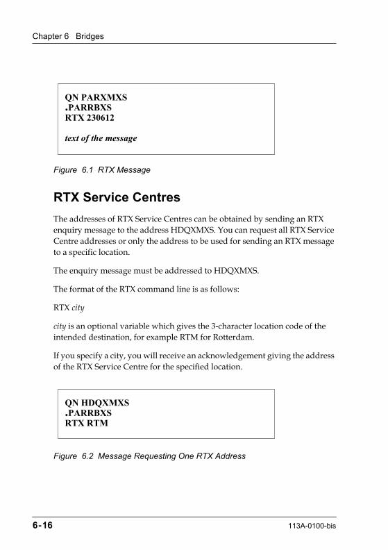
Chapter 6 Bridges
Figure 6.1 RTX Message
RTX Service Centres
The addresses of RTX Service Centres can be obtained by sending an RTX enquiry message to the address HDQXMXS. You can request all RTX Service Centre addresses or only the address to be used for sending an RTX message to a specific location.
The enquiry message must be addressed to HDQXMXS.
The format of the RTX command line is as follows:
RTX city
city is an optional variable which gives the 3-character location code of the intended destination, for example RTM for Rotterdam.
If you specify a city, you will receive an acknowledgement giving the address of the RTX Service Centre for the specified location.
Figure 6.2 Message Requesting One RTX Address
QN PARXMXS.PARRBXSRTX 230612
text of the message
QN HDQXMXS.PARRBXSRTX RTM
6-16 113A-0100-bis

RTX (Relay To Public Telex)
Figure 6.3 Acknowledgement of Message Requesting One RTX Address
If you do not specify a city, you will receive an acknowledgement giving the addresses of all RTX Service Centres listed by country and city.
Figure 6.4 Message Requesting All RTX Addresses
QU PARRBXS.HDQXMXSACK RTX RTMROTTERDAM NETHERLANDS
List of RTM RTX deliveries listed by countryCOUNTRY CITY RTX ADDRESSNETHERLANDSAMSTERDAMAMSXMXS
QN HDQXMXS.PARRBXSRTX
113A-0100-bis 6-17

Chapter 6 Bridges
Figure 6.5 Acknowledgement of Message Requesting All RTX Addresses
Delivery to Telex Machines
Messages received at the XMXS address are delivered, in their original format, to the telex number given in the RTX command line.
RTX Help
You can request help by sending an RTX message to the address HDQXMXS. The format of the RTX command line is as follows:
RTX HELP
QU PARRBXS.HDQXMXSACK RTX
Part 1 of 2
List of all RTX deliveries listed by country
COUNTRY CITY RTX ADDR------------ --------- --------ARGENTINA BUENOS ARIES BUEXMXSAUSTRALIA SYDNEY SYDXMXSAUSTRIA VIENNA VIEXMXSBAHRAIN BAHRAIN BAHXMXSBELGIUM BRUSSELS BRUXMXS...U. S. A. NEW YORK NYCXMXS
6-18 113A-0100-bis

RTX (Relay To Public Telex)
Figure 6.6 RTX HELP
You will receive an acknowledgement giving information on the RTX service.
QN HDQXMXS.PARRBXSRTX HELP
113A-0100-bis 6-19

Chapter
7
113A-0100-bis
Servers
This chapter explains how messages are transferred to and from the SITA Broadcast Service (RTB) using the RTB server.
RTB (Relay Through Broadcast)
RTB allows authorised users to broadcast Type B messages over the SITA and AFTN Networks at the same time by means of broadcast lists. Access to this service is based on the sending of commands to an RTB server. For more information refer to the RTB User Guide (Document Code: 213A).
The registration of RTB users is handled by HDQOAXS (Order Entry and Configuration).
RTB Broadcast Lists
There are 2 categories of broadcast list:
¥ Lists owned by a single registered RTB user. A user list can only be modified by the owner but can be used by all Type B users who have the same 2-letter company code as the owner.
¥ Lists owned by a given 2-letter company code. A company list can only be modified by the registered company supervisor but can be used by all Type B users who have the same 2-letter company code as the registered supervisor.
There is no limit to the number of lists that a user can create. There is no limit to the number of addresses that each list can contain, however, SITA recommends a maximum of 1500 addresses per list. The same list can contain SITA addresses, AFTN addresses, fax numbers and telex numbers. A list name can contain a maximum of 8 alphanumeric characters.
7-1

Chapter 7 Servers
Registered RTB users can create, delete, display, and modify their address lists. Each user can update their own lists at any time. Company lists can only be updated from a company supervisory station that is defined at the time of registration.
RTB Commands
All access to the RTB server is by means of machinable messages. The messages contain the instructions to the server. The RTB commands are as follows:
¥ HELP
Returns a message giving help to the user on the use of the RTB service.
This command is available to non-registered users.
¥ ADD broadcast-list optionaddress 1...address nEND
Adds the specified addresses to the named broadcast list. If the list does not exist, it is created. The available options are /M (multi-address messages, this is the default) and /S (single-address messages).
The END indicator is optional and only needs to be used if text is likely to be added after the list of addresses.
¥ CLEAR broadcast-list
Deletes all addresses from the named broadcast list. The list is also deleted.
¥ COPY broadcast-list1 broadcast-list2
Creates the new list broadcast-list2 and copies all addresses from broadcast-list1 to broadcast-list2.
7-2 113A-0100-bis

RTB (Relay Through Broadcast)
¥ DEL broadcast-list address 1... address nEND
Deletes the given addresses from the named broadcast list. If all addresses are deleted then the list is also deleted.
The END indicator is optional and only needs to be used if text is likely to be added after the list of addresses.
¥ DISP
Returns a message that displays the names of all broadcast lists available to the user.
¥ DISP broadcast-list
Returns a message that displays all addresses contained in the named broadcast list.
¥ EXAM
Returns a message that lists all registered RTB users with the same company code as the originator of the EXAM message.
This command is available to non-registered users.
¥ EXAM user-address
An extension of the EXAM command that returns a message listing all broadcast lists belonging to the specified user-address.
This command is available to non-registered users.
113A-0100-bis 7-3
Chapter 7 Servers
¥ EXAM user-address broadcast-list
An extension of the EXAM command that returns a message listing all the addresses in the named broadcast-list belonging to the specified user-address.
This command is available to non-registered users.
¥ MERGE broadcast-list1 broadcast-list2 TO broadcast-list3
Creates the new list broadcast-list3 and copies all addresses from broadcast-list1 and broadcast-list2 to broadcast-list3.
¥ SEARCH [user-address] search-address
Searches broadcast lists for the search-address. To search all lists owned by a specific user, include the user-address.
This command is available to non-registered users.
¥ STAT identifier
Checks the availability of the RTB service. The optional variable identifier allows the user to specify an ID of up to 8 alphanumeric characters. The ID can be used to match the command message to the acknowledgement for tracking purposes.
This command is available to non-registered users.
¥ XMIT broadcast-list [owner-address] message text
Sends the message text to all addresses contained in the named broadcast list.
The owner-address must be included if the originator of the command does not own the broadcast-list.
This command is available to non-registered users.
7-4 113A-0100-bis
RTB (Relay Through Broadcast)
¥ XMITnn broadcast-list [owner-address]
Sends the message text to all addresses contained in the named broadcast list but cancels the message if it is not transmitted within the limit nn.
nn defines the permissible transmission delay in hours from 01 to 12. The starting time for calculating the delay is taken from the date/time group of the XMIT message.
The owner-address must be included if the originator of the command does not own the broadcast-list.
This command is available to non-registered users.
RTB Message Format
Messages to the RTB server are machinable service messages. They must include the following elements which are specific to the RTB service:
¥ RTB server address ¥ RTB command line
RTB Server Address
The message must be addressed to HDQXMXS, the RTB server. Other addresses can be included.
RTB Command Line
The instruction for the server is specified in an RTB command line which must be the first line of the text section. The RTB command line must be composed of the following elements in the order shown:
¥ the letters RTB ¥ one space ¥ the RTB command
Only one command can be included in each machinable message.
Figure 7.1 shows an example of a message to the RTB server.
113A-0100-bis 7-5
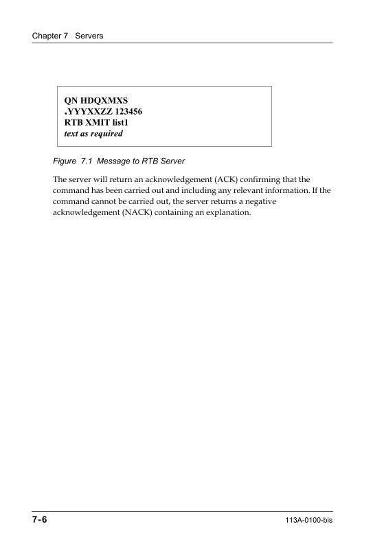
Chapter 7 Servers
Figure 7.1 Message to RTB Server
The server will return an acknowledgement (ACK) confirming that the command has been carried out and including any relevant information. If the command cannot be carried out, the server returns a negative acknowledgement (NACK) containing an explanation.
QN HDQXMXS.YYYXXZZ 123456RTB XMIT list1text as required
7-6 113A-0100-bis

Chapter
8
113A-0100-bis
Overview of Connection Types
The following chapters describe the connection types available at the time of publication. SITA will receive customer requirements for other connection types and will try to provide these connections wherever feasible.
The currently available connection types for Type B messaging services are: ¥ AX.25 ¥ MSL - Full-duplex ¥ MSL - Half-duplex ¥ P1X24 - P1024 or P1124 ¥ SITATEX Synchronous ¥ SITATEX ÒDialÓ - X.28 and PSTN ¥ Telex ¥ Asynchronous ¥ X.25 ¥ MATIP ¥ MQ ¥ WebAccess
Note: If required, a P1020 connection can also be made available.
For each connection type, the information is given under the following standard headings:
¥ General Description, including the speed and code ¥ Services available ¥ Protocols used ¥ Message Format, specifically for Heading and Ending ¥ Message protection methods ¥ Availability of statistics and automatic performance report
8-1

Chapter 8 Overview of Connection Types
¥ User options, message handling options implemented at circuit level in the local SITA switching system
Hand-Delivery
SITA also provides hand-delivery of messages where necessary.
The definition of hand-delivery includes the following:
¥ UserÕs Messenger ¥ Telegram via PTN (see Chapter 5) ¥ Mail ¥ Fax (excluding the BFAX Service) ¥ Telephone
The following additional rules apply to collection of messages by the userÕs messenger:
1. A record must be made of messages to be collected.
2. This record must be signed by the recipient when messages are handed over.
8-2 113A-0100-bis
Chapter
9
113A-0100-bis
AX.25
General Description
AX.25 is a medium speed connection used for connecting airline reservation or switching systems. The connection is bit-oriented and uses synchronous link control.
Speed - Up to 64 Kb
Codes - Padded Baudot, ASCII
Services
The connection is used to provide an ACS customer service. The ACS service can have access to the following SITA services:
¥ Gateways to AFTN ¥ Facsimile Service (BFAX) ¥ Data Processing ¥ Global Broadcast (RTB) ¥ Gateway to Public Telex (RTX) ¥ Gateway to X.400 Service (GMS X.400) and SMTP ¥ MQ-enabled Application
Protocols
The AX.25 protocol is a subset of X.25 that ensures the exchange of conventional (Type B), conversational, and other traffic types.
9-1
Chapter 9 AX.25
AX.25 is a 2-tier procedure. It uses the P3000/LAP-B protocol at the level of the Data Link Layer and X.25 at the levels of the Network and Transport Layers.
For full details of the AX.25 protocol, refer to Chapter X of the ATA/IATA Interline Communications Manual and the SITA AX.25 on DIS Operational Handbook.
Message Format
Messages must be composed in accordance with the standard format defined in Chapter 2. No Heading or Ending is required.
Message Protection
Message protection is assumed by the BATAP protocol. See the SITA document SIHN HLS/MSS - User System Application to Application Type B Protection (Ref. 100/LP-SN-030).
There is no serial number check on this type of connection.
Statistics and Performance Report
The following statistics are recorded:
¥ Number of messages received and transmitted ¥ Number of characters received and transmitted ¥ Number of data and service blocks received and transmitted
An automatic performance report is generated giving the following details:
¥ System outage ¥ Link outage ¥ Traffic handled
9-2 113A-0100-bis
User Options
User Options
The following options are available at circuit level:
¥ Output Address Stripping done prior to output ¥ Short Address Line added prior to output
When this option is used, Output Address Stripping cannot be used for the same circuit.
¥ Multiple delivery - if several addresses contained in the message are destined for the same subscriber, this message will be sent as many times as these addresses occur
¥ All service messages are sent to the intercept position of the operator room and not back to the subscriber
¥ Spacing signal in US characters
113A-0100-bis 9-3
Chapter
10
113A-0100-bis
MSL - Full-duplex
General Description
MSL (Multi-Station Line) - full-duplex is a low speed multidrop configuration where several stations are connected to the same line.
Speed - The speed ranges from 50 to 600 Baud depending on the SITA equipment to which the connection is made
Code - Baudot
Services
This connection is used to provide a TTY customer service. The TTY service can have access to the following SITA services:
¥ Gateways to AFTN ¥ Facsimile Service (BFAX) ¥ Data Processing ¥ Global Broadcast (RTB) ¥ Gateway to Public Telex (RTX) ¥ Gateway to X.400 Service (GMS X.400) and SMTP ¥ MQ-enabled Applications
Protocols
The connection supports the 81D1 and S626 protocols. Refer to the following documentation for details of these protocols:
¥ Bell System 81D1
10-1
Chapter 10 MSL - Full-duplex
¥ C.W. S626 Description. Automatic Teleprinter Selective Calling System for use with computer switching centres - January 1978
¥ SITA document MSL on Concentrator (Ref. 100/LP-SN-013)
Message Format
Messages must be composed in accordance with the standard format defined in Chapter 2. The specific formats for the Heading and Ending are described in the following sections.
Heading
The heading is mandatory both for messages transmitted from the MSL station to the SITA Network and from the SITA Network to the MSL station. The heading has the following format:
¥ The characters ZCZC ¥ The CDC(s) of the station(s) addressed. Each CDC must be followed by
one lettershift ¥ One space ¥ The message Serial Number (SNR) ¥ One space ¥ An optional Message Identity consisting of the Date/Time Group (TOD)
Note: The sequence CDC LTRS SNR can be repeated if the same message is being sent from the SITA Network to several stations on the same MSL.
Ending
In the absence of a bilateral agreement, this section is mandatory.
For messages from the MSL station to the SITA Network, the ending section consists of the following elements in the order shown:
¥ figureshift ¥ the letter H in figure position (this will normally be the symbol #) ¥ lettershift
10-2 113A-0100-bis

Message Protection
For messages from the SITA Network to the MSL station, the ending section consists of the following elements in the order shown:
¥ carriage return ¥ the page feed sequence of 4 to 7 linefeeds ¥ 4 letters N in an uninterrupted sequence, preceded by lettershift when
necessary ¥ a minimum of 5 or 6 lettershifts unless otherwise determined by a
bilateral agreement
Message Protection
Transmission protection is assumed by the Polling/Calling techniques of the protocol itself.
A check can be performed on the serial number if it is present.
The HLS generates a midnight continuity check and resets both transmitted and received serial numbers. The midnight check message contains both the last sent (LS) and last received (LR) serial numbers.
Statistics and Performance Report
The following statistics are recorded:
¥ Number of messages transmitted and received on the MSL trunk ¥ Number of characters transmitted and received on the MSL trunk ¥ Number of messages transmitted and received by each MSL station ¥ Number of characters transmitted and received by each MSL station
No automatic performance report is generated for this type of connection.
User Options
The following options are available at circuit level:
¥ Output Address Stripping done prior to output
113A-0100-bis 10-3
Chapter 10 MSL - Full-duplex
¥ Short Address Line added prior to outputWhen this option is used, Output Address Stripping cannot be used for the same circuit.
¥ No Time of Delivery added for output ¥ Multiple delivery - if several addresses contained in the message are
destined for the same subscriber, this message will be sent as many times as these addresses occur
¥ All service messages are sent to the intercept position of the operator room and not back to the subscriber
10-4 113A-0100-bis

Chapter
11
113A-0100-bis
MSL - Half-duplex
General Description
MSL (Multi-Station Line) - half-duplex is a low speed multidrop configuration where several stations are connected to the same line.
Speed - The speed ranges from 50 to 600 Baud depending on the SITA equipment to which the connection is made
Code - Baudot
Services
This connection is used to provide TTY or SITATEX customer services. These customer services can have access to the following SITA services:
¥ Gateways to AFTN ¥ Facsimile Service (BFAX) ¥ Data Processing ¥ Global Broadcast (RTB) ¥ Gateway to Public Telex (RTX) ¥ Gateway to X.400 Service (GMS X.400) and SMTP ¥ MQ-enabled Applications
Protocols
The connection supports the 83B1, 83B3, and S619 protocols. Refer to the following documentation for more information:
11-1
Chapter 11 MSL - Half-duplex
¥ Bell System Data Communications Technical Reference. 83B3 teletypewriter Selective Call System. System Operator and Interface Specification - September 1967
¥ C.W. S619 Half-Duplex System Facilities Specification - Issue 6 October 1969 ¥ SITA document MSL on Concentrator (Ref. 100/LP-SN-013)
Message Format
Messages must be composed in accordance with the standard format defined in Chapter 2. The specific formats for the Heading and Ending are described in the following sections.
Heading
A heading is not required for a message transmitted from the subscriber to SITA. On a message transmitted from SITA to the subscriber, the heading has the following format:
¥ The characters ZCZC ¥ The CDC(s) of the station(s) addressed. Each CDC must be followed by
one lettershift ¥ One space ¥ The message Serial Number (SNR) ¥ One space ¥ An optional Message Identity consisting of the Date/Time Group (TOD)
Note: The sequence CDC LTRS SNR can be repeated if the same message is being sent to several stations on the same MSL.
Ending
In the absence of a bilateral agreement, this section is mandatory.
For messages both from and to the subscriber using the 83B3 protocol, the ending section consists of the following elements in the order shown:
¥ figureshift ¥ the letter H in figure position (this will normally be the symbol #)
11-2 113A-0100-bis
Message Protection
¥ lettershift
For messages both from and to the subscriber using the S619 protocol, the ending consists of 4 letters N, that is NNNN.
Message Protection
Transmission protection is assumed by the Polling/Calling techniques of the protocol itself.
A check can be performed on the serial number if it is present.
Statistics and Performance Report
The following statistics are recorded:
¥ Number of messages transmitted and received on the MSL trunk ¥ Number of characters transmitted and received on the MSL trunk ¥ Number of messages transmitted and received by each MSL station ¥ Number of characters transmitted and received by each MSL station
No automatic performance report is generated for this type of connection.
User Options
The following options are available at circuit level:
¥ Output Address Stripping done prior to output ¥ Short Address Line added prior to output
When this option is used, Output Address Stripping cannot be used for the same circuit.
¥ No Time of Delivery added for output ¥ No trailer. A trailer consists of 5 lettershift characters ¥ Multiple delivery - if several addresses contained in the message are
destined for the same user, this message will be sent as many times as these addresses occur
¥ All service messages are sent to the intercept position of the operator room and not back to the subscriber
113A-0100-bis 11-3
Chapter
12
113A-0100-bis
P1X24
General Description
P1X24 can be either P1024 or P1124. P1X24 is used for connecting airline reservation or switching systems. It is a medium speed bit-oriented connection that uses synchronous link control.
Speed - up to 64 Kb according to the SITA equipment to which the connection is made
Codes - Padded Baudot, ASCII
Services
P1X24 is used to provide an ACS customer service. The ACS customer service can have access to the following SITA services:
¥ Gateways to AFTN ¥ Facsimile Service (BFAX) ¥ Data Processing ¥ Global Broadcast (RTB) ¥ Gateway to Public Telex (RTX) ¥ Gateway to X.400 Service (GMS X.400) and SMTP ¥ MQ-enabled Applications
Protocol
The connection uses the P1024 protocol which is a communications control procedure defined by ATA/IATA. P1024 has two main functions: synchronous link control, and message control. Refer to the ATA/IATA Interline Communications Manual for details.
12-1

Chapter 12 P1X24
Message Format
Messages must be composed in accordance with the standard format defined in Chapter 2. The specific requirements for the Heading and Ending are described in the following sections.
Heading
No heading is required in either Padded Baudot or ASCII code.
Ending
No ending is required in Padded Baudot.
When using ASCII code, the ETX character is always followed by an EOT character in messages transmitted from the SITA Network to the user. The EOT character is optional in messages transmitted from the user to the SITA Network.
Message Protection
Message protection is provided by a CML (Clear Message Label) Link Control Block. The CML is used even for a single block.
There is no serial number check on this type of connection.
Statistics and Performance Report
The following statistics are recorded:
¥ Number of messages transmitted and received ¥ Number of characters transmitted and received ¥ Number of data and service blocks transmitted and received
An automatic performance report is generated containing the following information:
¥ System outage
12-2 113A-0100-bis
User Options
¥ Link outage ¥ Traffic handled
User Options
The following options are available at circuit level:
¥ Output Address Stripping done prior to output ¥ Short Address Line added prior to output
When this option is used, Output Address Stripping cannot be used. ¥ Multiple delivery - if several addresses contained in the message are
destined for the same subscriber, this message will be sent as many times as these addresses occur
¥ All service messages are sent to the intercept position of the operator room and not back to the subscriber
¥ Spacing signal in US characters
113A-0100-bis 12-3

Chapter
13
113A-0100-bis
SITATEX Synchronous
General Description
This connection can be to a stand-alone, a PC cluster station, a LAN gateway, or a SITATEX mail-enabled application.
Speed - 2400 to 19200 bps
Code - ASCII
Services
The connection is used to provide a SITATEX customer service. The SITATEX service can have access to the following SITA services:
¥ Gateways to AFTN ¥ Facsimile Service (BFAX) ¥ Data Processing ¥ Global Broadcast (RTB) ¥ Gateway to Public Telex (RTX) ¥ Gateway to X.400 Service (GMS X.400) and SMTP ¥ MQ-enabled Applications
Protocol
The connection uses the P1024C protocol. Refer to the SITA document P1024C Communication Control Specification (Ref. 100/LP-SD-001) for details.
13-1

Chapter 13 SITATEX Synchronous
Message Format
Messages must be composed in accordance with the standard format defined in Chapter 2. Messages do not require either a Heading or an Ending section.
Message Protection
Message protection is assumed by the BATAP protocol. The BATAP used for SITATEX is not exactly the same as used on other types of connections. See the SITATEX 3 Technical Manual (Ref. PZ/PC-TN002).
Statistics and Performance Report
Statistics are recorded on the number of messages transmitted and received.
An automatic performance report showing the volume of traffic exchange is sent to operations staff.
User Options
The following options are available at circuit level: ¥ Output Address Stripping done prior to output ¥ Short Address Line added prior to output
When this option is used, Output Address Stripping cannot be used for the same circuit.
¥ No Time of Delivery added on output
13-2 113A-0100-bis
Chapter
14
113A-0100-bis
SITATEX ÒDialÓ (X.28 and PSTN)
SITA currently provides two modes of dial access for the SITATEX service:
¥ X.28 ¥ PSTN (Public Switched Telephone Network)
However, the SITATEX Dial for X.28 service is progressively replacing the PSTN dial service.
SITATEX for X.28 Dial Service
General Description
This connection provides all SITATEX message and file transfer capabilities. The link is established by dialling one of the SITA X.28 PADs which are available throughout the world. This allows mobile users to connect to the SITA Network by means of a simple telephone call.
The SITATEX Dial software includes a file that lists the telephone numbers for all of the Dial Access systems.
Speed - 1200 to 9600 bps
Code - ASCII
Services
The SITATEX dial service can have access to the following SITA services:
¥ Gateways to AFTN ¥ Facsimile Service (BFAX)
14-1
Chapter 14 SITATEX ÒDialÓ (X.28 and PSTN)
¥ Data Processing ¥ Global Broadcast (RTB) ¥ Gateway to Public Telex (RTX) ¥ Gateway to X.400 Service (GMS X.400) and SMTP ¥ MQ-enabled Applications
Protocol
This connection type uses the international X.28 standard. A session is established between a SITATEX station and an X.28 PAD.
Message Format
Messages must be composed in accordance with the standard format defined in Chapter 2. Heading and Ending sections are not required.
Message Protection
Message protection is provided by the BATAP protocol. The BATAP used for SITATEX is not exactly the same as used on other types of connections. See the SITATEX 3 Technical Manual (Ref. PZ/PC-TN002).
Statistics and Performance Report
The following statistics are available at circuit level:
¥ Number of messages transmitted and received ¥ Number of characters transmitted and received
No automatic performance report is generated for this type of connection.
User Options
The following options are available at circuit level:
¥ Output Address stripping ¥ Short Address Line
14-2 113A-0100-bis
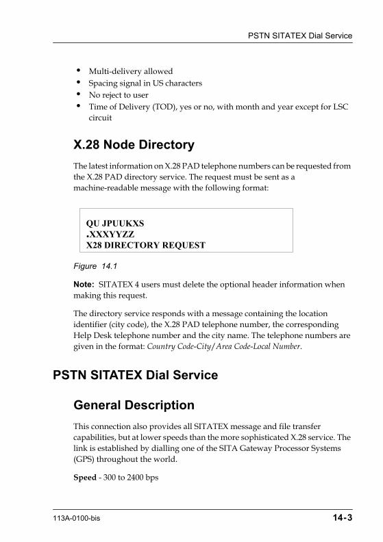
PSTN SITATEX Dial Service
¥ Multi-delivery allowed ¥ Spacing signal in US characters ¥ No reject to user ¥ Time of Delivery (TOD), yes or no, with month and year except for LSC
circuit
X.28 Node Directory
The latest information on X.28 PAD telephone numbers can be requested from the X.28 PAD directory service. The request must be sent as a machine-readable message with the following format:
Figure 14.1
Note: SITATEX 4 users must delete the optional header information when making this request.
The directory service responds with a message containing the location identifier (city code), the X.28 PAD telephone number, the corresponding Help Desk telephone number and the city name. The telephone numbers are given in the format: Country Code-City/Area Code-Local Number.
PSTN SITATEX Dial Service
General Description
This connection also provides all SITATEX message and file transfer capabilities, but at lower speeds than the more sophisticated X.28 service. The link is established by dialling one of the SITA Gateway Processor Systems (GPS) throughout the world.
Speed - 300 to 2400 bps
QU JPUUKXS.XXXYYZZX28 DIRECTORY REQUEST
113A-0100-bis 14-3
Chapter 14 SITATEX ÒDialÓ (X.28 and PSTN)
Code - ASCII
Services
The PSTN SITATEX dial service can have access to the following SITA services:
¥ Gateways to AFTN ¥ Facsimile Service (BFAX) ¥ Data Processing ¥ Global Broadcast (RTB) ¥ Gateway to Public Telex (RTX)
Protocol
This connection type uses an asynchronous proprietary protocol for establishing a session between PSTN stations and the GPS. Refer to Appendix D, SITATEX PSTN, of the SITATEX 3 Technical Manual (Ref. PZ/PC-TN002) for details.
Message Format
Messages must be composed in accordance with the standard format defined in Chapter 2. Heading and Ending sections are not required.
Message Protection
Message protection is assumed by the BATAP protocol. The BATAP used for SITATEX is not exactly the same as used on other types of connections. See the SITATEX 3 Technical Manual (Ref. PZ/PC-TN002).
There is no serial number checking on this type of connection.
Statistics and Performance Report
The following options are available at circuit level:
14-4 113A-0100-bis
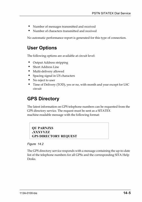
PSTN SITATEX Dial Service
¥ Number of messages transmitted and received ¥ Number of characters transmitted and received
No automatic performance report is generated for this type of connection.
User Options
The following options are available at circuit level:
¥ Output Address stripping ¥ Short Address Line ¥ Multi-delivery allowed ¥ Spacing signal in US characters ¥ No reject to user ¥ Time of Delivery (TOD), yes or no, with month and year except for LSC
circuit
GPS Directory
The latest information on GPS telephone numbers can be requested from the GPS directory service. The request must be sent as a SITATEX machine-readable message with the following format:
Figure 14.2
The GPS directory service responds with a message containing the up-to-date list of the telephone numbers for all GPSs and the corresponding SITA Help Desks.
QU PARNJXS.XXXYYZZGPS DIRECTORY REQUEST
113A-0100-bis 14-5

Chapter
15
113A-0100-bis
Telex
General Description
A Telex connection provides access to public telex networks around the world. It simplifies the exchange of messages between the airlines and their many industry correspondents who may or may not be SITA Network users.
The connection to a concentrator is always made by means of a TANU (Telex Answering and Numbering Unit).
Frequently used correspondent telex numbers can be mapped to SITA codes in the MHS tables. This allows SITA Network users to continue to use familiar SITA 7-character addresses while sending to off-network destinations.
Speed - 50 Bd
Code - Baudot
Services
This connection is used to provide a Teletype (TTY) customer service. The TTY service can have access to the following SITA services:
¥ Gateways to AFTN ¥ Facsimile Service (BFAX) ¥ Data Processing ¥ Global Broadcast (RTB) ¥ Gateway to X.400 Service (GMS X.400) and SMTP ¥ MQ-enabled Applications
Note: The RTX service is not available to Telex users.
15-1
Chapter 15 Telex
Protocol
The connection uses the ATA/IATA Telex and Interface Exchange protocols. Refer to the ATA/IATA Interline Communications Manual for details.
Message Format
Messages must be composed in accordance with the standard format defined in Chapter 2. The specific formats for the message Heading and Ending are described in the following sections.
Heading
The heading contains the elements needed for communications control on a given circuit and must not exceed one line containing a maximum of 69 characters.
The standard heading may be simplified, depending on the mode of operation of a circuit, and subject to a bilateral agreement.
Standard Heading
The standard heading must be composed of the following elements in the order shown:
¥ start-of-message signal ¥ circuit identification ¥ message serial number (optional for subscriber) ¥ supplemental information ¥ spacing signal
Start-of-Message Signal (mandatory)
The start-of-message signal identifies the beginning of a message. The signal consists of one of the following:
¥ the characters ZCZC followed by one space ¥ CR LF
15-2 113A-0100-bis

Message Format
Circuit IdentiÞcation (optional)
This identifies the circuit on which the message is transmitted. The circuit identification consists of one of the following:
¥ Three letters of which the first one identifies the transmitting end, the second one the receiving end, and the third one the number of the channel
¥ One figure preceded by a figureshift. The figure identifies the number of the channel when more than one channel is operated between the same centres
Do not leave a space between the circuit identification and the message serial number which follows it.
Message Serial Number (optional)
This element is optional for the subscriber as any continuity check is done on the trunk Telex and not on the individual user's connection. The message serial number identifies each individual message within a sequence of messages transmitted. The serial number consists of three figures in the range 001 to 000 (representing 1000).
If the preceding signal was in lower case (Letters), the message serial number must be preceded by one figureshift.
Supplemental Information (optional)
This allows the inclusion of additional information relating to the message header which is not provided in any of the other heading elements. The supplemental information is preceded by one space.
If this section is used to provide time of delivery information (TOD), this is composed of the following elements in the order shown:
¥ Day: 2-figure group ¥ Time in UTC: 4-figure group
Spacing Signal
The spacing signal signifies the end of the heading. It consists of 5 spaces.
113A-0100-bis 15-3
Chapter 15 Telex
SimpliÞed Heading
The simplified heading is composed of the following elements in the order shown:
¥ CR ¥ LF
Ending
In the absence of a bilateral agreement, this section is mandatory.
The ending section consists of the following elements in the order shown:
¥ one carriage return ¥ the page feed sequence composed of 4 to 7 linefeeds ¥ 4 letters N in an uninterrupted sequence, preceded by one lettershift
when necessary ¥ a minimum of 5 or 6 lettershifts unless otherwise determined by a
bilateral agreement
Message Protection
Message protection is assured by 2 Telex answerbacks exchanged once at connection time and again before disconnecting.
If required, a continuity check can be done on the trunk telex. There is no option to have a continuity check done on the user's connection.
Statistics and Performance Report
At HLS level statistics are recorded on the number of messages transmitted and received on each telex trunk.
No automatic performance report is generated for this type of connection.
15-4 113A-0100-bis

User Options
User Options
The following options are available at circuit level:
¥ Output Address Stripping done prior to output ¥ Short Address Line added prior to output
When this option is used, Output Address Stripping cannot be used for the same circuit.
¥ No Time of Delivery added on output
113A-0100-bis 15-5

Chapter
16
113A-0100-bis
Asynchronous
General Description
The asynchronous connection type is a Point-to-Point Telegraphic connection in which a link connects only 2 centres (a station to a SITA centre), as opposed to the multidrop line configuration in which several stations are connected to the same link.
Speed - 50 to 9600 Bd
Codes - Baudot, ASCII
Services
The connection type is used to provide an asynchronous customer service, for example connection of a TTY or PC. This customer service can have access to the following SITA services:
¥ Gateways to AFTN ¥ Facsimile Service (BFAX) ¥ Data Processing ¥ Global Broadcast (RTB) ¥ Gateway to Public Telex (RTX) ¥ Gateway to X.400 Service (GMS X.400) and SMTP ¥ MQ-enabled Applications
Note: The version of SITATEX used for this type of connection does not include the document transfer facility.
16-1
Chapter 16 Asynchronous
Protocol
The connection uses the ATA/IATA TTY protocol. Refer to the ATA/IATA Interline Communications Manual for details.
Message Format
Messages must be composed in accordance with the standard format defined in Chapter 2. The specific formats for the Heading and Ending are described in the following sections.
Note: The SITATEX application handles the heading and ending automatically.
Heading
The heading contains the elements needed for communications control on the circuit being used for transmission. The heading must consist of only one line containing a maximum of 69 characters.
The composition of the heading may be simplified, depending on the mode of operation of a circuit, and subject to a bilateral agreement.
The complete heading, if used, must be composed of the following elements in the order shown:
¥ start-of-message signal ¥ circuit identification ¥ message serial number ¥ supplemental information ¥ spacing signal
Start-of-Message Signal
The start-of-message signal identifies the beginning of a message.
In Baudot code, the signal consists of the characters ZCZC followed by one space.
16-2 113A-0100-bis

Message Format
In ASCII code, the signal consists of the characters ZCZC followed by the SOH character.
Circuit IdentiÞcation
This identifies the circuit on which the message is transmitted. The circuit identification consists of one of the following:
¥ Three letters of which the first one identifies the transmitting end, the second one the receiving end, and the third one the number of the channel
¥ One figure (preceded by a figureshift, if required). The figure identifies the number of the channel when more than one channel is operated between the same centres
Do not leave a space between the circuit identification and the message serial number which follows it.
Message Serial Number
The message serial number identifies each message within a sequence of messages. The serial number consists of three figures in the range 001 to 000 (representing 1000).
In Baudot code, if the circuit identification was in lower case (Letters), the message serial number must be preceded by one figureshift.
Supplemental Information
This allows the inclusion of information relating to the message heading which is not provided in any of the other elements. The supplemental information is preceded by one space.
If this section is used to provide time of delivery information (TOD), this is composed of the following elements in the order shown:
¥ Day: 2-figure group ¥ Time in UTC: 4-figure group
Spacing Signal
The spacing signal signifies the end of the heading.
113A-0100-bis 16-3
Chapter 16 Asynchronous
In both Baudot code and ASCII code, the spacing signal consists of a minimum of 5 spaces.
Ending
In the absence of a bilateral agreement, this section is mandatory.
In Baudot code the ending section consists of the following elements in the order shown:
¥ one carriage return ¥ the page feed sequence composed of 4 to 7 linefeeds ¥ 4 letters N in an uninterrupted sequence, preceded by one lettershift
when necessary ¥ a minimum of 5 or 6 lettershifts unless otherwise determined by a
bilateral agreement
In ASCII code the ending is composed of the following elements in the order shown:
¥ CR ¥ LF ¥ LF ¥ LF ¥ EOT
Note: There must be 3 line feeds (LF) between the carriage return (CR) and end-of-text (EOT) characters.
Message Protection
Message protection is assumed by the protocol and by serial number comparison. A midnight continuity check is carried out.
There is no end-to-end mechanism on this type of connection. The connection operates in pure freewheeling mode.
There is no session mechanism for SITATEX on this type of connection.
16-4 113A-0100-bis
Statistics and Performance Report
Statistics and Performance Report
The following statistics are recorded:
¥ Number of messages transmitted and received ¥ Number of characters transmitted and received
User Options
The following options are available at circuit level:
¥ Output Address Stripping done prior to output ¥ Short Address Line added prior to output
When this option is used, Output Address Stripping cannot be used for the same circuit.
¥ No Time of Delivery added to output ¥ Multiple delivery - if several addresses contained in the message are
destined for the same subscriber, this message will be sent as many times as these addresses occur
¥ All service messages are sent to the intercept position of the operator room and not back to the originator
¥ Input Message Acknowledgement (IMA) used
113A-0100-bis 16-5

Chapter
17
113A-0100-bis
X.25
General Description
Host systems can now access the SITA Network by means of an X.25 SVC (Switched Virtual Circuit). The standard features of the CCITT X.25 recommendation 1988 (blue book) are supported.
The Type B over X.25 SVC connects by mean of an HPAD (Host Packet assembler/Disassembler) housed in the MHS FEP (Front End Processor). The HPAD function allows the MHS access through X.25.
Note: Type B traffic management over X.25 SVC requires the implementation of the Specification of SITA Network Access for exchange of Mixed Type A/Type B Transparent traffic over X.25 SVCs and of BATAP. If requested, the specifications can be provided by SITA.
Speed - Up to 64 Kb
Codes - ASCII, Padded Baudot
Services
The full range of services is available as follows:
¥ Gateways to AFTN ¥ Facsimile Service (BFAX) ¥ Data Processing ¥ Global Broadcast (RTB) ¥ Gateway to Public Telex (RTX) ¥ Gateway to X.400 Service (GMS X.400) and SMTP ¥ MQ-enabled Applications
17-1
Chapter 17 X.25
Protocol
The standard features of the CCITT X.25 recommendation 1988 (blue book) are supported. In addition, the following optional facilities are offered:
¥ non-standard default packet size (up to 1024) ¥ non-standard default window size ¥ default throughput class assignment ¥ flow control parameters negotiation ¥ throughput class negotiation ¥ call redirection ¥ hunt group
The protocol conversion between X.25 and the Type B protocol is entirely handled by the HPAD function of the MHS-FEP.
Message Format
Messages must be composed in accordance with the standard format defined in Chapter 2. The Type B message plus the BATAP trailer set up by the host application is encapsulated into X.25 packets.
Message Protection
The BATAP protocol must be implemented by the X.25 host for end-to-end protection. See the SITA document SIHN HLS/MSS - User System Application to Application Type B Protection, (ref. 100/LP-SN-030).
Statistics and Performance Report
The following statistics are recorded:
¥ Number of messages received and transmitted ¥ Number of characters received and transmitted ¥ Number of data and service blocks received and transmitted
An automatic performance report is generated giving the following details:
17-2 113A-0100-bis
User Options
¥ System outage ¥ Link outage ¥ Traffic handled
User Options
The following options are available at circuit level:
¥ Call directionThe user can choose the SVC establishment direction. The SVC is either established by the MHS-HPAD at initialisation time and maintained as long as the MHS is available or established by the user host. The two options are not mutually exclusive and in the event of collision, the call from the host is maintained.
¥ Text codeThe user must specify at the time of subscription whether the text code used is ASCII or Padded Baudot.
113A-0100-bis 17-3

Chapter
18
113A-0100-bis
MATIP-Type B (MATIP access to Type B)
General Description
MATIP-Type B (MATIP access to Type B) is being introduced primarily to meet the expressed requirements of the Type B customers for Type B over TCP/IP. It is developed by a working group initiated and led by SITA with the participation of several Airlines and CRS, and with 3rd Party Vendor Support for MATIP including CISCO, IBM, Unisys.
MATIP-Type B (MATIP access to Type B) enables customer hosts running several air transport business applications to access Type B service for business messaging communications using SITA IP-based network services including Intranet Connect, AeroNet, LAN Access, Frame Relay Access.
For this purpose, a standard protocol MATIP (Mapping of Airline Traffic over IP) is developed to support the Air Transport Industry in the migration from proprietary protocols to TCP/IP. MATIP is ratified by IETF (Internet Engineering Task Force) as RFC2351. MATIP provides a common Interface for Type A and Type B with no impact on existing applications.
Once customer applications are linked with BATAP/MATIP, a unique IP connection to the SITA Network for access to Type B service is established that ensures Type B message communications between different applications and with different Type B users and business partners.
BATAP is to ensure reliable delivery of Type B messages between two applications.
MATIP is an end-to-end protocol for the transport of Type B (and Type A) traffic over TCP. It ensures session establishment and closure, and data transfer on top of TCP/IP.
18-1

Chapter 18 MATIP-Type B (MATIP access to Type B)
SITA implementation specifications are posted at the SITA web site www.sita.com (search for MATIP), assistance and consultancy can be provided on request.
The customer will continue to benefit from reliability, security, high availability and performance of the Type B service necessary for its operational and mission critical message exchanges.
This chapter provides reference material for MATIP; for detailed, up-to-date specifications, please refer to Type B ACS Traffic Over TCP/IP, FSD - MZ/OR/B98060004.
Speed - Depends on local ACS access network connectivity
Code - ASCII
Services
The full range of services is available as follows:
¥ Gateways to AFTN ¥ Facsimile Service (BFAX) ¥ Data Processing ¥ Global Broadcast (RTB) ¥ Gateway to Public Telex (RTX) ¥ Gateway to X.400 Service (GMS X.400) and SMTP ¥ MQ-enabled Applications
Protocol
The standard features of a TCP/IP network are implemented.
¥ DNS for service name resolution ¥ Firewalls for service protection
18-2 113A-0100-bis

Message Format
Message Format
Messages must be composed in accordance with the standard format defined in Chapter 2. The Type B message plus the BATAP trailer set up by the host application is encapsulated in TCP segments.
Message Protection
BATAP (Type B Application to Application Protocol) must be implemented by the MATIP host for end-to-end protection.
See the SITA document SIHN HLS/MSS - User System Application to Application Type B Protocol, (ref. 100/LP-SN-030).
Statistics and Performance Report
The following statistics are recorded:
¥ Number of messages received and transmitted ¥ Number of characters received and transmitted ¥ Number of data and service blocks received and transmitted
An automatic performance report is generated giving the following details:
¥ System outage ¥ Link outage ¥ Traffic handled
User Options
The user can choose to act as:
¥ a CLIENT ¥ a CLIENT and SERVER
As the client, the ACS is responsible for establishing the connection to the service.
113A-0100-bis 18-3

Chapter 18 MATIP-Type B (MATIP access to Type B)
As both client and server, both the ACS and the SITA Switching System may establish the connection.
18-4 113A-0100-bis

Chapter
19
113A-0100-bis
MQ-Type B (MQ access to Type B)
General Description
The MQ-Type B service enables customer applications to use MQSeries off-the-shelf package to access Type B and related messaging services over TCP/IP for exchange of business messages as diverse as seat availability, flight plans, spare parts, cargo and several other messages.
Type B messaging is predominantly used for operational messaging in the air transport industry to exchange messages with structured data content between applications. The MQ-Type B service couples large availability of MQSeries with the strength of the SITA Type B service to provide the capability to a wide range of applications within different systems to access Type B and associated services for inter-application communication within and between various air transport companies.
MQSeries is a message-oriented off-the-shelf software package that enables reliable application-to-application message exchanges across heterogeneous systems using IP-based network services. MQSeries is available on several platforms including:
¥ IBM MVS, TPF, OS/400, AIX ¥ Microsoft Windows 3.1, 95&98, NT ¥ Unisys 2200/A and U series ¥ Sun, SunOS, Solaris ¥ Compaq OpenVMS, UNIX ¥ Hewlett-Packard HP-UX ¥ UNIX
19-1
Chapter 19 MQ-Type B (MQ access to Type B)
Once customer applications are linked with MQSeries, a unique IP connection to the SITA Network for access to MQ-Type B service is established that ensures Type B message communications between different applications and with different business partners, as well as the use of other complementary services.
An MQ-Type B service enables any customer sending messages from its host to use MQSeries over a wide range of SITA IP-based network services including Intranet Connect, AeroNet, LAN Access or Frame Relay Access to send and receive Type B messages.
The customer will continue to benefit from reliability, security, high availability and performance of Type B service necessary for its operational and business sensitive message exchanges. On the customer MQ interface to MQ-Type B, standard MQ communications and reliability features are used.
Customers can use an MQ-Type B service from wherever they have a dedicated IP connection to the SITA Network (Intranet Connect, LANAS, AeroNet, FR).
Connections via MQSeries may be made from an MQSeries Client or MQSeries Queue Manager to the SITA MQSeries Queue Manager using TCP/IP. Using the features of MQSeries the customer has complete freedom in naming those MQSeries elements under his control.
This access method also allows access to the SITA Type B messaging domain from any platform and using any programming language supported by MQSeries.
Services
In addition to the Type B messaging service, the MQ-Type B may be used to access the following services among others:
¥ Gateways to other e-mail networks such as SMTP and X400 ¥ Facsimile Services such as BFAX and FDS ¥ Data Processing ¥ Global Broadcast (RTB) ¥ Gateway to Public Telex (RTX)
19-2 113A-0100-bis

Protocol
Protocol
The standard features of a TCP/IP network are implemented such as DNS name service, firewalls and proxies for protection.
Message Format
Although MQSeries has no format requirements for the messages contained within its envelope, this service assumes all messages are legal Type B messages composed in accordance with the standard format defined in Chapter 2.
MQSeries then encapsulates this Type B message within a MQSeries envelope and using the MQSeries high level channel protocol moves the messages over a TCP/IP network.
Message Protection
MQSeries guarantees once and only once delivery. Using Persistent messages, the MQ-Type B service sends all messages as Persistent and requires the customer to do so as well.
Statistics and Performance Report
The following statistics are recorded:
¥ Number of messages received and transmitted ¥ Number of characters received and transmitted
An automatic performance report is generated giving the following:
¥ System outage ¥ Link outage ¥ Traffic handled
113A-0100-bis 19-3
Chapter 19 MQ-Type B (MQ access to Type B)
User Options
Users may chose to connect to SITA using an MQSeries Client or Queue Manager. In addition, message splitting and reassemble or rejection if too big are also available options.
MQ Manager Customer Connection to MQSeries
Each Customer remote queue MQ Manager requires one normal local queue, one local transmission queue, one remote queue definition containing the name of the local transmission queue, and two channels. The channels may have any name but must be the same on both ends. One channel should be a SDR/RCVR channel with a transmission queue name of the local transmission queue.
Note: The mq_GetQueueName is on the SITA queue manager. The mq_PutQueueName is on the customer queue manager.
On incoming messages, the customer always comes in through the proxy on port 1414. MQ Client Customer Connection to MQSeries.
For customers connecting by MQSeries clients there must be two local queues and one SVRCONN channel. There may be a different SVRCONN for each client or one or more clients may use the same SVRCONN channel. No transmission queues are required.
Note: Both mq_GetQueueName and mq_PutQueueName are on the SITA queue manager.
Because there is only a single channel, incoming and outgoing messages both go through port 1414 through the proxy.
19-4 113A-0100-bis

Chapter
20
113A-0100-bis
Web-Type B
General Description
Web-Type B is a web based electronic mailbox service associated to the Type B messaging domain. It enables customers to use a web browser (such as Netscape Navigator or Microsoft Explorer) to access the Type B mailbox and exchange messages with Type B users, Internet mail users or for sending messages to fax and telex worldwide.
Web-Type B may be deployed as a stand-alone or through a large or small LAN environment.
Customer mailboxes are accessible by connecting to: http://typebmail.sita.com using a web browser from a PC or NC.
Web-Type B service is available only over the SITA IP Network, and cannot be accessed over the Internet. Customers can use Web-Type B from wherever they have a dedicated connection to the SITA Network (Intranet Connect, LAN-AS, AeroNet, FR). For Dial access Aeronet dial is available, and PPP dial will be available early in the year 2000
Web-Type B user requires a Type B address on the service, and may also request to have that address configured on SITA Type B gateway in order to exchange messages with Internet or X.400 E-mail users.
Additionally, a simple web interface is designed to enable applications to interface the service for communications with various applications and Type B users.
User Id and password protect access to the mailbox. Every single message send by the customer is uniquely acknowledged and traceable by the service.
The service provides all common e-mail functionalities including:
20-1

Chapter 20 Web-Type B
¥ view message list (sent and received messages) ¥ compose message, includes simplified entry for Internet addresses and
fax numbers ¥ view message, view next/previous message ¥ forward message (quote), reply to message sender or to all ¥ delete message, delete all messages, sent messages, read messages ¥ password change with automatic administration confirmation message ¥ print, copy/paste, and other features through local browser
Services
In addition to Type B messaging service, the Web-Type B may be used to access the following services among others:
¥ Gateways to other e-mail networks such as SMTP and X400 ¥ Facsimile Service (BFAX) ¥ Data Processing ¥ Global Broadcast (RTB) ¥ Gateway to Public Telex (RTX) ¥ MQ enabled applications
Protocol
The standard features of a TCP/IP network are implemented such as DNS name service, firewalls and proxies for protection. Standard HTTP is used between the web browser and the server.
Message Format
Type B messages are presented in a GUI (graphic user interface) format. The fields of the Type B message (e.g. recipient, subject line, message body, etc.) have their own GUI input widgets that are found in a typical GUI mail tool.
20-2 113A-0100-bis

Message Protection
The Web-Type B server uses HTML and Javascript to present the message on the user interface. The message is then converted to standard Type B message format for Type B communications.
Message Protection
User access to the service is verified using a password-based encryption mechanism.
Every message send by the user is uniquely acknowledged and traceable by the service.
All messages received for a user are kept on the SITA message store until explicitly deleted.
Statistics and Performance Report
The following statistics are recorded:
¥ Number of messages received and transmitted ¥ Number of characters received and transmitted
An automatic performance report is generated giving the following:
¥ System outage ¥ Link outage ¥ Traffic handled
User Options
The same web interface is currently provided to all customers, so there are no user options required.
113A-0100-bis 20-3

Appendix
A
113A-0100-bis
ASCII/Baudot/ASCII Translation Table
Character Code Translation Table
The table starts with the ASCII character and shows how the character is translated into Baudot and then how the Baudot character is translated into ASCII.
Decimal, octal, and hexadecimal values are shown for the ASCII characters. The octal value given in the Baudot column corresponds to the Padded Baudot character as follows:
¥ bit 7 always = 1 ¥ bit 6 = 0 for letter mode, 1 for figure mode
In addition to the conventional notation for ASCII and Baudot characters, the table uses the following notation:
¥ delete - the character is not translated, it is deleted from the message ¥ let - lettershift ¥ fig - figureshift
ASCII BAUDOT ASCII
dec oct hex oct dec oct hex
NUL 00 000 00 delete
SOH 01 001 01 delete
STX 02 002 02 delete
ETX 03 003 03 delete
A-1
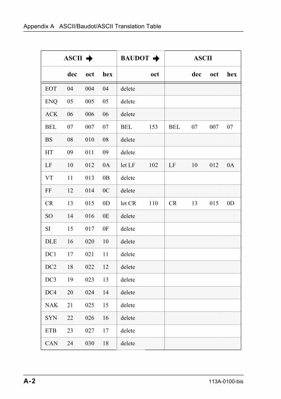
Appendix A ASCII/Baudot/ASCII Translation Table
EOT 04 004 04 delete
ENQ 05 005 05 delete
ACK 06 006 06 delete
BEL 07 007 07 BEL 153 BEL 07 007 07
BS 08 010 08 delete
HT 09 011 09 delete
LF 10 012 0A let LF 102 LF 10 012 0A
VT 11 013 0B delete
FF 12 014 0C delete
CR 13 015 0D let CR 110 CR 13 015 0D
SO 14 016 0E delete
SI 15 017 0F delete
DLE 16 020 10 delete
DC1 17 021 11 delete
DC2 18 022 12 delete
DC3 19 023 13 delete
DC4 20 024 14 delete
NAK 21 025 15 delete
SYN 22 026 16 delete
ETB 23 027 17 delete
CAN 24 030 18 delete
ASCII BAUDOT ASCII
dec oct hex oct dec oct hex
A-2 113A-0100-bis
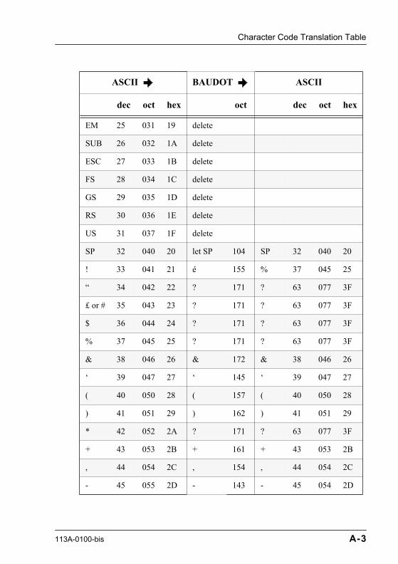
Character Code Translation Table
EM 25 031 19 delete
SUB 26 032 1A delete
ESC 27 033 1B delete
FS 28 034 1C delete
GS 29 035 1D delete
RS 30 036 1E delete
US 31 037 1F delete
SP 32 040 20 let SP 104 SP 32 040 20
! 33 041 21 � 155 % 37 045 25
Ò 34 042 22 ? 171 ? 63 077 3F
£ or # 35 043 23 ? 171 ? 63 077 3F
$ 36 044 24 ? 171 ? 63 077 3F
% 37 045 25 ? 171 ? 63 077 3F
& 38 046 26 & 172 & 38 046 26
Ô 39 047 27 Ô 145 Ô 39 047 27
( 40 050 28 ( 157 ( 40 050 28
) 41 051 29 ) 162 ) 41 051 29
* 42 052 2A ? 171 ? 63 077 3F
+ 43 053 2B + 161 + 43 053 2B
, 44 054 2C , 154 , 44 054 2C
- 45 055 2D - 143 - 45 054 2D
ASCII BAUDOT ASCII
dec oct hex oct dec oct hex
113A-0100-bis A-3

Appendix A ASCII/Baudot/ASCII Translation Table
. 46 056 2E . 174 . 46 056 2E
/ 47 057 2F / 175 / 47 057 2F
0 48 060 30 0 166 0 48 060 30
1 49 061 31 1 167 1 49 061 31
2 50 062 32 2 163 2 50 062 32
3 51 063 33 3 141 3 51 063 33
4 52 064 34 4 152 4 52 064 34
5 53 065 35 5 160 5 53 065 35
6 54 066 36 6 165 6 54 066 36
7 55 067 37 7 147 7 55 067 37
8 56 070 38 8 146 8 56 070 38
9 57 071 39 9 170 9 57 071 39
: 58 072 3A : 156 : 58 072 3A
; 59 073 3B = 176 = 61 075 3D
< 60 074 3C ? 171 ? 63 077 3F
= 61 075 3D = 176 = 61 075 3D
> 62 076 3E ? 171 ? 63 077 3F
? 63 077 3F ? 171 ? 63 077 3F
@ 64 100 40 ? 171 ? 63 077 3F
A 65 101 41 A 103 A 65 101 40
B 66 102 42 B 131 B 66 102 42
ASCII BAUDOT ASCII
dec oct hex oct dec oct hex
A-4 113A-0100-bis

Character Code Translation Table
C 67 103 43 C 116 C 67 103 43
D 68 104 44 D 111 D 68 104 44
E 69 105 45 E 101 E 69 105 45
F 70 106 46 F 115 F 70 106 46
G 71 107 47 G 132 G 71 107 47
H 72 110 48 H 124 H 72 110 48
I 73 111 49 I 106 I 73 111 49
J 74 112 4A J 113 J 74 112 4A
K 75 113 4B K 117 K 75 113 4B
L 76 114 4C L 122 L 76 114 4C
M 77 115 4D M 134 M 77 115 4D
N 78 116 4E N 114 N 78 116 4E
O 79 117 4F O 130 O 79 117 4F
P 80 120 50 P 126 P 80 120 50
Q 81 121 51 Q 127 Q 81 121 51
R 82 122 52 R 112 R 82 122 52
S 83 123 53 S 105 S 83 123 53
T 84 124 54 T 120 T 84 124 54
U 85 125 55 U 107 U 85 125 55
V 86 126 56 V 136 V 86 126 56
W 87 127 57 W 123 W 87 127 57
ASCII BAUDOT ASCII
dec oct hex oct dec oct hex
113A-0100-bis A-5

Appendix A ASCII/Baudot/ASCII Translation Table
X 88 130 58 X 135 X 88 130 58
Y 89 131 59 Y 125 Y 89 131 59
Z 90 132 5A Z 121 Z 90 132 5A
[ 91 133 5B ? 171 ? 63 077 3F
\ 92 134 5C ? 171 ? 63 077 3F
] 93 135 5D ? 171 ? 63 077 3F
^ 94 136 5E ? 171 ? 63 077 3F
_ 95 137 5F ? 171 ? 63 077 3F
Ô 96 140 60 ? 171 ? 63 077 3F
a 97 141 61 A 103 A 65 101 41
b 98 142 62 B 131 B 66 102 42
c 99 143 63 C 116 C 67 103 43
d 100 144 64 D 111 D 68 104 44
e 101 145 65 E 101 E 69 105 45
f 102 146 66 F 115 F 70 106 46
g 103 147 67 G 132 G 71 107 47
h 104 150 68 H 124 H 72 110 48
i 105 151 69 I 106 I 73 111 49
j 106 152 6A J 113 J 74 112 4A
k 107 153 6B K 117 K 75 113 4B
l 108 154 6C L 122 L 76 114 4C
ASCII BAUDOT ASCII
dec oct hex oct dec oct hex
A-6 113A-0100-bis

Character Code Translation Table
m 109 155 6D M 134 M 77 115 4D
n 110 156 6E N 114 N 78 116 4E
o 111 157 6F O 130 O 79 117 4F
p 112 160 70 P 126 P 80 120 50
q 113 161 71 Q 127 Q 81 121 51
r 114 162 72 R 112 R 82 122 52
s 115 163 73 S 105 S 83 123 53
t 116 164 74 T 120 T 84 124 54
u 117 165 75 U 107 U 85 125 55
v 118 166 76 V 136 V 86 126 56
w 119 167 77 W 123 W 87 127 57
x 120 170 78 X 135 X 88 130 58
y 121 171 79 Y 125 Y 89 131 59
z 122 172 7A Z 121 Z 90 132 5A
{ 123 173 7B ? 171 ? 63 077 3F
| 124 174 7C ? 171 ? 63 077 3F
} 125 175 7D ? 171 ? 63 077 3F
~ 126 176 7E ? 171 ? 63 077 3F
DEL 127 177 7F delete
NUL 100 delete
LS 137 delete
ASCII BAUDOT ASCII
dec oct hex oct dec oct hex
113A-0100-bis A-7
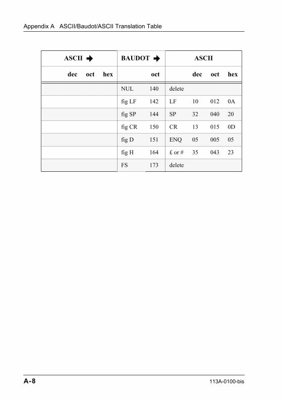
Appendix A ASCII/Baudot/ASCII Translation Table
NUL 140 delete
fig LF 142 LF 10 012 0A
fig SP 144 SP 32 040 20
fig CR 150 CR 13 015 0D
fig D 151 ENQ 05 005 05
fig H 164 £ or # 35 043 23
FS 173 delete
ASCII BAUDOT ASCII
dec oct hex oct dec oct hex
A-8 113A-0100-bis
113A-0100-bis
Glossary
This glossary defines the terminology used in this manual. If you do not find the term you are looking for, see the SITA Glossary of Acronyms and Technical Terms, Document Code: 100B.
Address Stripping
Removal, from the address line used for routing, of all addressee indicators, except those for which the receiving system is responsible.
Addressee
The person, office, or system for which the contents of a message are intended.
Addressee Indicator
A group of characters that identifies the delivery station of a message.
AFTN
Aeronautical Fixed Telecommunications NetworkAn integrated worldwide system of aeronautical fixed circuits provided as part of the aeronautical service for the exchange of messages between stations in the network.
Alternative Centre
A centre which relays messages between two communication centres not able to communicate via the predetermined route.
Alternative Routing
Routing of messages via circuits other than those prescribed by the predetermined routing (see Alternative Centre).
Glossary-1
Glossary
ARQ
Automatic Return QueryA system used to control and correct errors in a transmission link.
ASCII
American Standard Code for Information InterchangeIn this code, each character is represented by a unique combination of 7 bits.
ATA
Air Transport Association of AmericaA gathering of US domestic airlines that monitors, by mutual agreement, the common interest of air transportation.
AX.25
Implementation of the X.25 protocol defined by IATA and implemented on the DTN, based on PVCs.
BATAP
Type B Application to Application ProtocolA protocol implemented between customer terminals and the SITA network to ensure end-to-end message protection.
Baud Rate
The number of changes in modulation bits that can be transmitted in 1 second, by definition, the reciprocal of the time of the shortest signal element in the character.
Baudot
A code used for transmission of data in which 5 bits represent one character. Baudot is sometimes referred to as a 5-bit code, 5-channel code, 5-unit code, or teletype code although it is no longer limited to teletype use.
BCS
Type B Concentrator System
Glossary-2 113A-0100-bis

Glossary
Bridge
A communications product that interconnects two computer networks or systems which have the same or similar characteristics.
CCITT
Comit� Consultatif International T�l�graphique et T�l�phonique.Also known as the International Telegraph and Telephone Consultative Committee. One of the main committees of the ITU.
CDC: Call Directing Code
Code used in a Multi-Station Line (MSL) system to identify the receiver part of a station. The code is used to call the station (to invite it to receive).
Channel
In SITA terminology, a channel is one of the physical communication paths used to transmit information on a link.
Continuity Check
A check made on a circuit or circuits in a connection to verify that a path (for transmission of data, speech, and so on) exists.
Data Block (Transmission)
A group of characters to be transmitted over a data link as a unit, provided with an envelope used for protection and control.
Double Signature
The 2-character alphanumeric airline/organisation designator that identifies the airline/organisation accepting the SITA charge for the transmission costs of the message.
Full-duplex (FDX)
Data transmission over a circuit in both directions at the same time.
GatewayA communications product that provides a connection between two different network protocols. It acts as a translator to change one network protocol into the attached network protocol.
113A-0100-bis Glossary-3

Glossary
Half-duplex (HDX)
Data transmission over a circuit capable of transmitting in either direction, one direction at a time.
Handling
Relating to data switching systems, the word ÒhandlingÓ designates the complete processing of a set of data from its input into a system (network or switching centre) through to its output.
HLS
High Level SystemPerforms Type B message handling, control, mass storage and associated tasks, Type B message switching, and interfaces with the local low level network.
IATA
International Air Transport AssociationA gathering of international air carriers formed to protect the common interest of international air transportation in the fields of air fares, technology, currency exchange, and ÒinterlinedÓ agreements.
ICAO
International Civil Aviation OrganisationResponsible for the setting up and application of rules for air traffic control, and operates the AFTN.
Interface
A means permitting the interconnection of equipment or systems with different functions or modes of operation.
Interline MessageA message originated by one airline and addressed to one or more other airlines.
Glossary-4 113A-0100-bis
Glossary
ITU
International Telecommunications UnionIts main purpose is to establish legal and technical rules for the interconnection of member countries and telegraph networks, and to agree on common tariffs for international telegrams.
Leased Circuit
A service whereby a circuit (or circuits) of the public network is made available for exclusive use to a user or group of users (ITU).
Link
Data link - one or more telecommunications circuits between two points for the purpose of data interchange (IATA).
Transmission link - a means of transmission with specified characteristics between two points. The type of transmission path or the capacity is normally indicated; for example radio link, coaxial link.
Message Handling System (MHS)
The SITA systems that handle the Type B message acceptance, storage, and routing.
MSL
Multi Station Line (Party Line)A low speed multi-drop line configuration. Several stations are connected to the same line.
OFTS
Overseas Fixed Telecommunications ServiceThe British Airways network which was developed from the former BOAC network. The OFTS is organised like a club and most of the member airlines are from British Commonwealth countries.Members provide services to other members on a reciprocal basis.
113A-0100-bis Glossary-5

Glossary
P.1020
SITA protocol comprising a processor-to-processor asynchronous link control procedure providing the logic for control and assurance of the full-duplex low-speed teletype circuits connecting two processors.
P1024
SITA protocol comprising a communications control procedure providing synchronous link control and message control.
PAD
Packet Assembler/DisassemblerA functional unit that permits DTEs (Data Terminal Equipment) not equipped for packet switching to access a packet-switched network.
PDN
Public Data NetworkA shared resource data network that offers data communications services to public subscribers.
Priority Code
A 2-letter combination preceding the first address of an address section that determines the order of transmission.
Protocol
A mutually agreed upon formal set of conventions governing the format and control of information exchange between two systems.
PSTN
Public Switched Telephone Network
PTN
See Public Telegraph Network
Glossary-6 113A-0100-bis

Glossary
PTT
An abbreviated term that represents the Post, Telephone, and Telegraph administrations of the world (it does not apply to Canada and the United States).
Public Telegraph Network (PTN)
A network set up to perform a telegraph service for the public. It belongs to a telecommunications operating body (administration or private) and may be used to provide general telegraph service, telex service or leased circuits service (ITU).
Service Message
Message exchanged between centres and/or stations concerning the operation of the network.
SMI
Standard Message IdentifierIn machine-readable messages SMI is a 3-character mnemonic abbreviation identifying the message type. The SMI is always the first element of the text section and can be processed by computer whilst retaining a mnemonic value for human operators.
SNA
System Network ArchitectureAn IBM hierarchical network architecture which allows point-to-point synchronous dialogue between the host and each terminal.
SNADS
SNA Distribution ServicesAn IBM distributed services architecture based on SNA for telecommunication services. It consists of a set of software tools added to SNA at the application level. SNADS allows end-users (terminals, PC, distributed processing computer) to speak together in asynchronous mode.
113A-0100-bis Glossary-7
Glossary
Supplemental Address
An address line preceding the normal address line of a message and containing only those addressee indicators to be actioned. Also known as Short Address Line.
TANU
Telex Answering Numbering Unit
TBC
Type B Concentrator
TDM
Time Division Multiplexer
Telecommunications System
An entity of telecommunications facilities under the control of one organisation.
Transfer CentreThe centre where messages are transferred between the SITA Network and another telecommunications system.
TTY
TeletypeTTY is used to designate a teleprinter communication terminal used for telegraphic traffic. Teletype is in fact a trademark of the TELETYPE CORPORATION.
Unixmail
Developed and marketed by UNIPLEX, Unixmail is an office automation system designed to run in the UNIX environment.
UTC
Universal Time Co-ordinatedIn French the term is TUC (Temps Universel Compens�). This is the time system used on the SITA Network and is the same as GMT.
Glossary-8 113A-0100-bis

Glossary
X.25
The CCITT recommendation for the first 3 layers of the ISO OSI model. X.25 provides an interface between a network DTE (Data Terminal Equipment) and a network DCE (Data Circuit-terminating Equipment) for terminals operating in the packet mode and connected to public data networks by a dedicated circuit.
X.28
A CCITT recommendation that defines the DCE/DTE interface between start-stop mode terminal equipment accessing the PAD facility and a PDN in the same country. X.28 is used for SITATEX Dial access.
X.400
The set of CCITT recommendations that define a universal standard for a Message Handling System (MHS), permitting the store and exchange of messages between users (persons or computer applications) on a store and forward operation mode.
113A-0100-bis Glossary-9

113A-0100-bis
Index
Aacceptable character codes 1-7acceptable messages 3-10address line
normal 2-9short 2-8
address mapping, Type B/X.400 5-8address out of use 3-8address section 2-4
acceptance check 3-3format error 3-4transfer from PTN 6-13
addressee indicator 2-10AFTN 5-1AFTN to AFTN 5-7AFTN transfer
message in AFTN format 5-2message in SITA format 5-3
ambiguous O/R name 5-15ASCII
general description 2-1ASCII/Baudot translation
general description 2-3asynchronous
code 16-1ending 16-4heading 16-2message protection 16-4protocol 16-2services 16-1speed 16-1statistics and performance report 16-5user options 16-5
authorisation to use the SITA network 1-5AX.25
code 9-1
ending 9-2heading 9-2message protection 9-2protocol 9-1services 9-1speed 9-1statistics and performance report 9-2user options 9-3
BBACKLOG 4-2Baudot
general description 2-1padded, general description 2-1
Baudot/ASCII translationgeneral description 2-3
BFAX address 6-2
Ccancelled messages 3-2cancelling a partly-transmitted
message 2-21check on
address section 3-3origin section 3-4
codeasynchronous 16-1AX.25 9-1MSL - full-duplex 10-1MSL - half-duplex 11-1P1X24 12-1PSTN 14-4synchronous 13-1telex 15-1X.25 17-1
Index-1
Index
X.28 14-1code unknown 3-7COL (Collation) 2-19component sections of Type B message 2-3,
3-17connection types, overview 8-1CONT OFF 4-3CONT ON 4-4content too long 5-15continuity check
by MHS 3-16periodic 3-15
continuity control 3-14copy indicator 2-11COR (Correction Message) 2-18
Ddata characters between messages 3-5delivery notification, FAX service 6-5delivery of SS and QS messages
extra rules 3-17delivery to
fax destination 6-4telex machines 6-18
destination address 2-10unknown 3-7
destination, invalid 3-6directory
GPS 14-5X.28 nodes 14-3
diversion indicator 2-5diversion line 2-4document transfer, Type B to X.400 5-11double signature 2-13DUPE TO FOLLOW 2-19
Eending
asynchronous 16-4AX.25 9-2MSL - full-duplex 10-2MSL - half-duplex 11-2P1X24 12-2PSTN 14-4synchronous 13-2
telex 15-4ending section 2-21end-of-address signal 2-6, 2-11
incorrect 3-4end-of-message signal
missing 3-4end-of-text signal 2-21
missing 3-4error messages
ambiguous O/R/name 5-15content too long 5-15exsv ads 3-3garbled address 3-4incor ads line 3-4incor EOA 3-4incor sig line 3-4incor SOA 3-3input not authorised 3-7invalid parameters 5-15line idle not rla 3-5line idle rla 3-5line open not rla 3-5line open rla 3-5loop detected 5-15maximum time expired 5-15msr 3-9MTA congestion 5-15multi errors 3-6no action ads 3-9no address found for X.400 server
QXTXXXX 5-13no disposal 3-8no EOM not rla 3-4no EOM not rla cct err 3-5no EOM rla 3-4no EOM rla cct err 3-5non iden origin 3-4not delivered to intended
recipient(s) 5-14nsma in ads line 3-7over length 3-6spurious 3-5stuck tape 3-6too long 3-6UA unavailable 5-15unauthor sign 3-7
Index-2 113A-0100-bis

Index
unknown 3-7unrecognised O/R name 5-16w/o EOM not rla 3-4w/o EOM rla 3-4
excessive number of identical characters 3-6exsv ads 3-3
FFAX 4-13FAX command line 6-3fax front page 6-4fax numbers, FAX service 6-2FAX service 6-2format error 3-2full telegraphic address, transfer to
PTN 6-10
GGA 4-5garbled address 3-4gateways 5-1, 7-1GMS X.400 service
rejected messages, Type B/X.400 5-13Type B address 5-9
GPS directory 14-5GPS DIRECTORY REQUEST 4-14group aliasing, Type B/X.400 5-10
Hhand-delivery 8-2header line, FAX service 6-4heading
asynchronous 16-2AX.25 9-2MSL - full-duplex 10-2MSL - half-duplex 11-2P1X24 12-2PSTN 14-4synchronous 13-2telex 15-2
heading section 2-3
Iincor ads line 3-4
incor EOA 3-4incor sig line 3-4incor SOA 3-3incorrect
end-of-address signal 3-4start-of-address signal 3-3
indicators used in the text 2-18input not authorised 3-7in-text addressing, Type B/X.400 5-8invalid
number of addresses 3-3origin or destination 3-6
invalid parameters 5-15
Lline idle not rla 3-5line idle rla 3-5line open not rla 3-5line open rla 3-5loop detected 5-15
Mmachine-readable service messages 4-1maximum time expired 5-15message
acceptance 3-1cancelled 3-2component sections 2-3, 3-17delivery to fax machines 6-2format for RTB 7-5format for RTX 6-14interrupted during reception 3-5
message composed inAFTN format 5-2SITA format 5-3
message handling systemgeneral description 1-6role 3-13
message identity 2-14message protection
asynchronous 16-4AX.25 9-2MSL - full-duplex 10-3MSL - half-duplex 11-3P1X24 12-2
113A-0100-bis Index-3
Index
PSTN 14-4synchronous 13-2telex 15-4X.25 17-2X.28 14-2
message transferAFTN to SITA 5-5SITA to AFTN 5-1to PTN 6-8
messages from X.400 systems 5-12messages to SITA MHS 4-1messages to SITA services 4-13MHS
continuity check by 3-16general description 1-6role 3-13
missingend-of-message signal 3-4end-of-text signal 3-4
MSL - full-duplexcode 10-1ending 10-2heading 10-2message protection 10-3protocol 10-1services 10-1speed 10-1statistics and performance report 10-3user options 10-3
MSL - half-duplexcode 11-1ending 11-2heading 11-2message protection 11-3protocol 11-1services 11-1speed 11-1statistics and performance report 11-3user options 11-3
msr 3-9MTA congestion 5-15multi errors 3-6multiple format errors 3-6
Nno action ads 3-9no address found for X.400 server
QXTXXXX 5-13no delivery point 3-8no disposal 3-8no EOM not rla 3-4no EOM not rla cct err 3-5no EOM rla 3-4no EOM rla cct err 3-5non iden origin 3-4non-delivery to X.400 destinations,
reasons 5-14non-printing characters, representation
of 2-2normal address line 2-9normal routing requires relay over the
PTN 6-8not delivered to intended recipient(s) 5-14nsma in ads line 3-7
Oorder of transmission 3-13origin section 2-12
acceptance check 3-4transfer from PTN 6-13
origin, invalid 3-6originator indicator 2-12over length 3-6
PP1X24
code 12-1ending 12-2heading 12-2message protection 12-2protocol 12-1services 12-1speed 12-1statistics and performance report 12-2user options 12-3
Padded Baudot, general description 2-1parts of messages not transferred to
PTN 6-11
Index-4 113A-0100-bis

Index
PDM (Possible Duplicate Message) 2-18periodic continuity check 3-15priority code 2-9prohibited
characters and character combinations 2-16
protocolasynchronous 16-2AX.25 9-1MSL - full-duplex 10-1MSL - half-duplex 11-1P1X24 12-1PSTN 14-4synchronous 13-1telex 15-2X.25 17-2X.28 14-2
PSTNcode 14-4ending 14-4GPS directory 14-5heading 14-4message protection 14-4protocol 14-4services 14-4speed 14-3statistics and performance report 14-4user options 14-5
PTN, transfer to 6-8Public Telegraph Network, transfer to 6-8
Rregistered telegraphic address
transfer to PTN 6-10transfer to SITA 6-12
rejected messagesFAX service 6-7Type B to X.400 5-13
relay through broadcasting service 7-1relay to public telex 6-14representation of non-printing
characters 2-2role of the SITA MHS 3-13ROUT (address) 4-15routing 3-12
errors 3-9routing indicator 2-5routing over PTN requested by
originator 6-9RPT ALL 4-6RPT BTN (serial number) 4-7RPT BTN (time of delivery) 4-9RPT ONE 4-10RTB 4-18
broadcast lists 7-1command line 7-5commands 7-2message format 7-5server address 7-5
RTB service 7-1RTX
address 6-15delivery to telex machines 6-18help 6-18service centres 6-16telex number 6-15
RTX (city) 4-19RTX (telex number) 4-18RTX HELP 4-20RTX service 6-14
SSAL 2-8sequence indicator of parts
added by originator 2-19automatic 3-10
serial numbering 3-14service centres, RTX 6-16service messages to MHS 4-1services
asynchronous 16-1AX.25 9-1MSL - full-duplex 10-1MSL - half-duplex 11-1P1X24 12-1PSTN 14-4synchronous 13-1telex 15-1X.25 17-1X.28 14-1
113A-0100-bis Index-5
Index
short address line 2-8signature 2-12
transfer to PTN 6-11transfer to SITA 6-12
SITATEXPSTN dial 14-3X.28 dial service 14-1
SITATEX ÒDialÓ 14-1spacing signal 2-7speed
asynchronous 16-1AX.25 9-1MSL - full-duplex 10-1MSL - half-duplex 11-1P1X24 12-1PSTN 14-3synchronous 13-1telex 15-1X.25 17-1X.28 14-1
spurious 3-5start-of-address signal 2-4
incorrect 3-3start-of-text signal 2-15STAT 4-11statistics and performance report
asynchronous 16-5AX.25 9-2MSL - half-duplex 11-3MSSL - full-duplex 10-3P1X24 12-2PSTN 14-4synchronous 13-2telex 15-4X.25 17-2X.28 14-2
STOP 4-12stuck tape 3-6supplementary address line 2-8synchronous
code 13-1ending 13-2heading 13-2message protection 13-2protocol 13-1services 13-1
speed 13-1statistics and performance report 13-2user options 13-2
Ttelegram text, transfer to SITA 6-12telegrams for transfer to the SITA
network 6-12telegraphic service indicator, transfer to
PTN 6-9telex
code 15-1ending 15-4heading 15-2message protection 15-4protocol 15-2services 15-1speed 15-1statistics and performance report 15-4user options 15-5
telex number, RTX 6-15text 2-16text section 2-15
transfer from PTN 6-14too long 3-6too many characters 3-6traffic protection 3-14traffic status message 4-11transfer
message to PTN 6-9transfer of telegram to SITA network 6-12transmission and protection 3-1transmission, order of 3-13Type B
general description 1-1network 1-5
Type B to X.400 5-8Type B to X.400, document transfer 5-11
UUA unavailable 5-15unaauthor sign 3-7unauthorised input 3-7unknown 3-7unknown address 3-7
Index-6 113A-0100-bis

Index
unknown destination address 3-7unrecognised O/R name 5-16user options
asynchronous 16-5AX.25 9-3MSL - full-duplex 10-3MSL - half-duplex 11-3P1X24 12-3PSTN 14-5synchronous 13-2telex 15-5X.25 17-3X.28 14-2
Ww//o EOM rla 3-4w/o EOM not rla 3-4
XX.25
code 17-1message protection 17-2protocol 17-2services 17-1speed 17-1statistics and performance report 17-2user options 17-3
X.28code 14-1message protection 14-2node directory 14-3protocol 14-2services 14-1speed 14-1statistics and performance report 14-2user options 14-2
X.28 node directory 14-3X.400 address format, in-text
addressing 5-9
113A-0100-bis Index-7