tyscor vs 2 central combination suction unit - Öncü dental · tyscor vs 2 central combination...
TRANSCRIPT
Tyscor VS 2 central combination suction unit
Installation and Operating Instructions
7186100001L02
1406
V00
2
EN

7186100001L02 1406V002 1
Mounting6 Prerequisites � � � � � � � � � � � � � � � � � � � � 14
6�1 Area of installation � � � � � � � � � � � � � � 146�2 Set-up alternatives � � � � � � � � � � � � � 146�3 Plumbing materials � � � � � � � � � � � � � 146�4 Hose materials � � � � � � � � � � � � � � � � 146�5 Notes on electrical connections � � � � 146�6 Notes on connection lines � � � � � � � � 15
7 Systemcomponents � � � � � � � � � � � � � � 157�1 Rinsing unit � � � � � � � � � � � � � � � � � � � 157�2 Exhaust air filter � � � � � � � � � � � � � � � � 157�3 Noise reducer � � � � � � � � � � � � � � � � � 157�4 Surge tank � � � � � � � � � � � � � � � � � � � 157�5 Flow accelerator � � � � � � � � � � � � � � � 16
8 Installation � � � � � � � � � � � � � � � � � � � � � � 178�1 Setting up hoses and pipes � � � � � � � 178�2 Fitting the rinsing unit � � � � � � � � � � � 188�3 Electrical connection � � � � � � � � � � � � 188�4 PCB electrical connections � � � � � � � 19
9 Operation � � � � � � � � � � � � � � � � � � � � � � � 209�1 Monitoring the appliance with Tys-
cor Pulse � � � � � � � � � � � � � � � � � � � � � 20
Usage10 LEDs� � � � � � � � � � � � � � � � � � � � � � � � � � � 22
10�1 Ready � � � � � � � � � � � � � � � � � � � � � � � 2210�2 Hose manifold start signal � � � � � � � � 2210�3 Fault � � � � � � � � � � � � � � � � � � � � � � � � 22
11 MonitoringtheappliancewithTys-corPulse � � � � � � � � � � � � � � � � � � � � � � � 2211�1 Monitor the function � � � � � � � � � � � � 2211�2 Querying the messages � � � � � � � � � � 2211�3 Carry out the task � � � � � � � � � � � � � � 2311�4 Creating a report � � � � � � � � � � � � � � � 23
EN
Contents
Importantinformation1 Documentation � � � � � � � � � � � � � � � � � � � 3
1�1 Warnings and symbols � � � � � � � � � � � 31�2 Notes on copyright � � � � � � � � � � � � � � 3
2 Safety � � � � � � � � � � � � � � � � � � � � � � � � � � � 42�1 Correct use � � � � � � � � � � � � � � � � � � � � 42�2 Incorrect use � � � � � � � � � � � � � � � � � � � 42�3 General safety notes � � � � � � � � � � � � � 42�4 Safe connection of appliance � � � � � � � 42�5 Qualified personnel � � � � � � � � � � � � � � 42�6 Protection against electrical current � � 52�7 Only use original parts � � � � � � � � � � � � 52�8 Transport � � � � � � � � � � � � � � � � � � � � � � 52�9 Disposal � � � � � � � � � � � � � � � � � � � � � � 5
Productdescription3 Overview � � � � � � � � � � � � � � � � � � � � � � � � 6
3�1 Delivery Contents � � � � � � � � � � � � � � � 73�2 Special accessories � � � � � � � � � � � � � � 73�3 Disposable materials � � � � � � � � � � � � � 73�4 Working parts and spare parts � � � � � � 7
4 Technicaldata � � � � � � � � � � � � � � � � � � � � 84�1 Model identification plate � � � � � � � � � 104�2 Note on Conformity � � � � � � � � � � � � � 10
5 Function � � � � � � � � � � � � � � � � � � � � � � � � 115�1 Separation system � � � � � � � � � � � � � � 115�2 Radial compressor � � � � � � � � � � � � � 125�3 LEDs and settings � � � � � � � � � � � � � � 125�4 Tyscor Pulse (optional) � � � � � � � � � � � 12
2 7186100001L02 1406V002
Contents
12 Disinfectionandcleaning � � � � � � � � � � 2312�1 For reasons of hygiene and perfect
function, after every patient treat-ment � � � � � � � � � � � � � � � � � � � � � � � � 23
12�2 Daily after completing treatment� � � � 2412�3 Once or twice a week before the
midday break � � � � � � � � � � � � � � � � � 24
13 Maintenance � � � � � � � � � � � � � � � � � � � � 25
Trouble-shooting14 TipsforOperatorsandTechnicians � � 26
14�1 General errors � � � � � � � � � � � � � � � � � 2614�2 Error messages in Tyscor Pulse � � � � 27
15 Transportingtheunit � � � � � � � � � � � � � � 28
Annex16 InformationonEMCaccordingto
EN 60601-1-2 � � � � � � � � � � � � � � � � � � � � 2916�1 General notes � � � � � � � � � � � � � � � � � 2916�2 Abbreviations � � � � � � � � � � � � � � � � � 2916�3 Guidelines and manufacturer's in-
formation � � � � � � � � � � � � � � � � � � � � � 2916�4 Table of calculation � � � � � � � � � � � � � 33
EN
7186100001L02 1406V002 3
The signal word differentiates between different levels of danger:
– DANGERHigh risk of danger of serious injury or death
– WARNINGPossible risk of danger of serious injury or death
– CAUTIONRisk of danger of minor injuries
– NOTICERisk of serious damage
FurthersymbolsThese symbols are used within the documenta-tion and on the unit itself:
Notes, e�g� special instructions con-cerning economical use of the unit�
Heed accompanying electronic docu-ments�
Monitor ambient conditions
Date of manufacture
Switch off the appliance (i� e� unplug and disconnect from mains)�
Wear protective gloves
1.2 NotesoncopyrightAll circuits, processes, names, software and ap-pliances quoted are protected under industrial property rights� Any reprinting of the technical documentation, in whole or in part, is subject to prior approval of Dürr Dental being given in writing�
1 DocumentationThese Installation and Operating Instructions form an integral part of the unit� They conform to the relevant version of the equipment and the status of technology valid at the time of first op-eration�
Dürr Dental cannot guarantee smooth operation and safe function of the unit and will not accept any liability where the instructions and notes contained in these installation and operating instruc-tions are not strictly observed�
This translation has been carried out in all good faith� The original German version is decisive� Dürr Dental accepts no liability for incorrect translation�
1.1 Warningsandsymbols
WarningsThe warnings in this document are there to point out possible injury to persons or damage to machinery� The following warning symbols are used:
General warning symbol
Warning - dangerous electrical voltage
Warning - the unit starts up automatical-ly
Biohazard warning
The warnings are structured as follows:
SIGNALWORDDescriptionoftypeandsourceofdangerPossible consequences of ignoring the safety warning here• Measures to be taken to avoid any
possible danger�
Importantinformation
EN
4 7186100001L02 1406V002
Important information
2.4 SafeconnectionofapplianceDanger can arise when connecting units with each other or to parts of the system (e�g� through discharge current)� • Only connect units when there can be no
question of danger to operator or to patient� • Only connect units when there can be no en-
vironmental impairment through such inter-connection�
• When it is not clear from the unit data sheets that such connection will cause no danger, then a qualified expert should be consulted to ensure no danger (e�g� one of the product manufacturers)�
During development and construction of the unit care has been taken to incorporate all require-ments of medical products as far as was possi-ble� As a result this appliance is suitable for in-stallation within medical supply equipment�• Observe the requirements under directive
93/42 EWG as well as all relevant standards when fitting into medical facilities�
A master copy of the system manu-facturer‘s declaration according to Article 12 of Directive 93/42/EWG can be found in our download sec-tion under www�duerr�de (Document No� 9000-461-264)�
2.5 Qualifiedpersonnel
InstructionsforusePersons who operate the appliance must, on the basis of their training and knowledge, en-sure safe and correct handling of the appliance� • Ensure personnel are trained in the correct us-
age of the appliance�
Installationandrepair• Installation, resetting, alterations, extensions
and repairs must be carried out by Dürr Den-tal or by qualified personnel specifically ap-proved and authorized by Dürr Dental�
2 SafetyDürr Dental has designed and constructed this appliance so that when used correctly there is no danger to people or property� Nevertheless, there are residual risks� Please follow the in-structions below carefully�
2.1 CorrectuseThe unit is designed to provide vacuum pres-sure in order to aspirate saliva, rinsing water and other fluids which are present during dental treatment and to transport these into the waste water system�This unit is also technically suitable for the aspi-ration nitrous oxide (laughing gas)� When de-signing a system that will also aspirate nitrous oxide ensure that the other components in the system are also suitable for this purpose� Those responsible for setting up the system must as-sess this and to approve and release the system for the aspiration of nitrous oxide�
Operating in combination with nitrous oxide is only permitted when the ex-haust air is transported to the outside of the building�
2.2 IncorrectuseAny use of this appliance above and beyond that specifically described in these instructions will be deemed to be as not according to the in-tended use� The manufacturer cannot be held li-able for any damage resulting from incorrect us-age� The user bears all risks�• Do not use this appliance to aspirate inflam-
mable or explosive gas mixtures�• The unit must not be used as a vacuum
cleaner�
2.3 Generalsafetynotes• Before using the appliance observe any and
all guidelines, laws, regulations and other re-strictions which may apply to the appliance�
• Before each use check the function and con-dition of the appliance�
• Do not convert or change the appliance in any way�
• Observe the Installation and Operating In-structions precisely�
• Keep the Installation and Operating Instruc-tions in an accessible place so that the opera-tor has instant access to them�
EN
7186100001L02 1406V002 5
Important information
2.9 Disposal
The unit may still be contaminated� In-form the waste management company so that they can take all necessary safe-ty steps�
• Non-contaminated parts (e�g� electronics, plastic and metal parts etc�) should be dis-posed of according to all valid waste disposal regulations�
• If you have any questions concerning the cor-rect disposal of parts please contact your dental trade supplier�
2.6 Protectionagainstelectricalcurrent
• When working on and with the appliance al-ways observe the local electrical safety proce-dures�
• Never come into contact with patients and open plug-in connections on the appliance at the same time�
• Damaged supply lines and connections must be replaced immediately�
Observeguidelinesforelectro-magneticcompatibilityformedicaldevices• Heed special precautionary measures with re-
gard to electromagnetic comparability (EMC) for medical products, see "16 Information on EMC according to EN 60601-1-2"�
2.7 Onlyuseoriginalparts• Only use accessories and special accessories
stipulated or approved by Dürr Dental� • Only use original working parts and spare
parts�
Dürr Dental accepts no liability for dam-age or injury caused by the use of ac-cessories, special accessories or parts other than original working parts and spare parts which were not specifically approved by the manufacturer�
2.8 Transport
WARNINGInfectionfromcontaminatedunit• Disinfect the unit before transport�• Close all media connections�
The original packaging offers the optimum pro-tection for the appliance during transport�If required, the original packaging for the unit can be ordered at Dürr Dental�
Dürr Dental cannot accept any liability for damage caused during transport by the use of unsuitable packaging, this is also valid during the warranty term�
• Only transport the appliance in its original packaging whenever possible�
• Keep the packing materials out of the reach of children�
EN
6 7186100001L02 1406V002
3 Overview
1
2
3
4
5
6
7
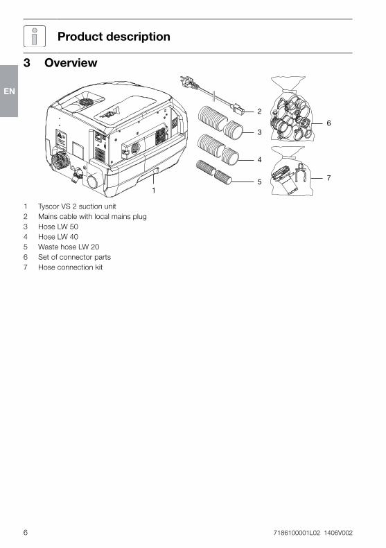
1 Tyscor VS 2 suction unit2 Mains cable with local mains plug3 Hose LW 50 4 Hose LW 405 Waste hose LW 206 Set of connector parts7 Hose connection kit
Productdescription
EN
7186100001L02 1406V002 7
Product description
3.1 DeliveryContentsThe following articles are included in the scope of delivery (possible variations due to country-specific conditions and/or import regulations):
TyscorVS2.................7186-01/... – Suction unit with 230 V, 1~, 50/60 Hz – Set of connector parts – Hose connection kit – Waste hose LW 20 – Hose LW 50 (0�6 m) – Hose LW 40 (1�5 m) – OroCup – Tyscor Pulse software (CD) – Quick start instructions
3.2 SpecialaccessoriesThe following items can be optionally used with the appliance: Surge tank � � � � � � � � � � � � � � � � � � 7130-991-00Wall mounting � � � � � � � � � � � � � � � � 7130-190-00Exhaust air filter � � � � � � � � � � � � � � 0705-991-53Exhaust air noise reducer � � � � � � � 0730-991-00Rinsing unit � � � � � � � � � � � � � � � � � � 7100-260-00Flow accelerator � � � � � � � � � � � � � � 7560-992-00Screed frame for flow accelerator � 7560-993-00
3.3 DisposablematerialsThe following materials are used when operating the appliance and must be ordered separately:Orotol plus 4 x 2�5-liter bottles/cartons � � � � CDS110P6150MD 555 special suction unit cleaner 4 x 2�5-liter bottles/cartons � � � � CCS555C6150
3.4 Workingpartsandspareparts
Information on spare parts can be found on the website portal for authorised specialist dealers under: www�duerrdental�net�
EN
8 7186100001L02 1406V002
Product description
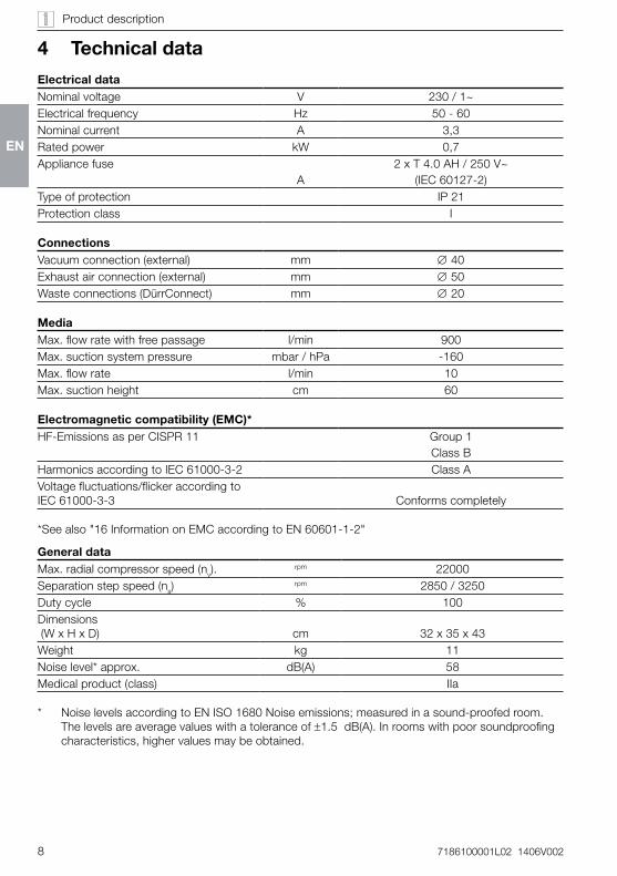
4 Technicaldata
ElectricaldataNominal voltage V 230 / 1~Electrical frequency Hz 50 - 60Nominal current A 3,3Rated power kW 0,7Appliance fuse
A2 x T 4�0 AH / 250 V~
(IEC 60127-2)Type of protection IP 21Protection class I
ConnectionsVacuum connection (external) mm ∅ 40Exhaust air connection (external) mm ∅ 50Waste connections (DürrConnect) mm ∅ 20
MediaMax� flow rate with free passage l/min 900Max� suction system pressure mbar / hPa -160Max� flow rate l/min 10Max� suction height cm 60
Electromagneticcompatibility(EMC)*HF-Emissions as per CISPR 11 Group 1
Class BHarmonics according to IEC 61000-3-2 Class AVoltage fluctuations/flicker according to IEC 61000-3-3 Conforms completely
*See also "16 Information on EMC according to EN 60601-1-2"
GeneraldataMax� radial compressor speed (nv)�
rpm 22000Separation step speed (ns)
rpm 2850 / 3250Duty cycle % 100Dimensions (W x H x D) cm 32 x 35 x 43Weight kg 11Noise level* approx� dB(A) 58Medical product (class) IIa
* Noise levels according to EN ISO 1680 Noise emissions; measured in a sound-proofed room� The levels are average values with a tolerance of ±1�5 dB(A)� In rooms with poor soundproofing characteristics, higher values may be obtained�
EN
7186100001L02 1406V002 9
Product description
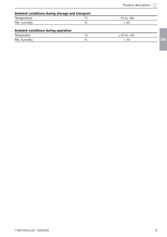
AmbientconditionsduringstorageandtransportTemperature °C -10 to +60Rel� humidity % < 95
AmbientconditionsduringoperationTemperatur °C +10 to +40Rel� humidity % < 70 EN
10 7186100001L02 1406V002
Product description
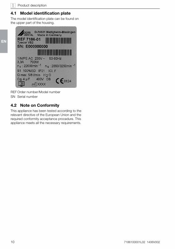
4.1 ModelidentificationplateThe model identification plate can be found on the upper part of the housing�
REF Order number/Model numberSN Serial number
4.2 NoteonConformityThis appliance has been tested according to the relevant directive of the European Union and the required conformity acceptance procedure� This appliance meets all the necessary requirements�
EN
7186100001L02 1406V002 11
Product description
5 Function
11
1
2
3
4
56
78
10
12
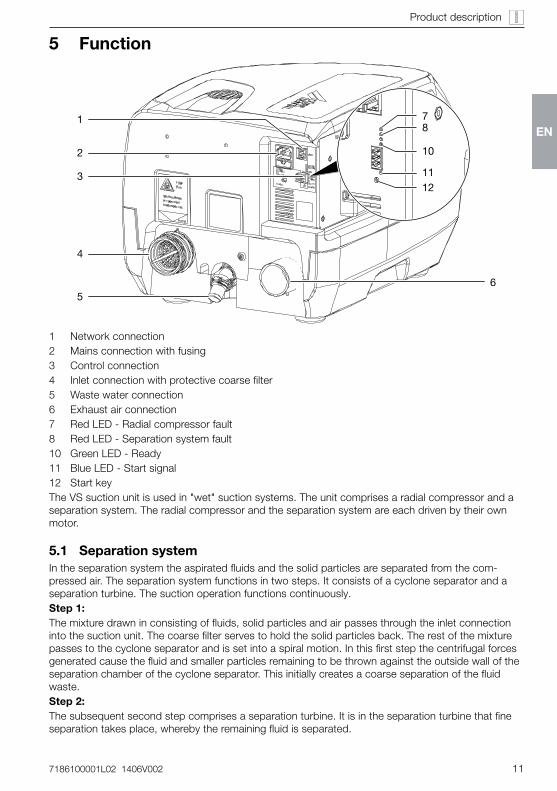
1 Network connection2 Mains connection with fusing3 Control connection4 Inlet connection with protective coarse filter5 Waste water connection6 Exhaust air connection7 Red LED - Radial compressor fault8 Red LED - Separation system fault10 Green LED - Ready11 Blue LED - Start signal12 Start keyThe VS suction unit is used in "wet" suction systems� The unit comprises a radial compressor and a separation system� The radial compressor and the separation system are each driven by their own motor�
5.1 SeparationsystemIn the separation system the aspirated fluids and the solid particles are separated from the com-pressed air� The separation system functions in two steps� It consists of a cyclone separator and a separation turbine� The suction operation functions continuously�Step1:The mixture drawn in consisting of fluids, solid particles and air passes through the inlet connection into the suction unit� The coarse filter serves to hold the solid particles back� The rest of the mixture passes to the cyclone separator and is set into a spiral motion� In this first step the centrifugal forces generated cause the fluid and smaller particles remaining to be thrown against the outside wall of the separation chamber of the cyclone separator� This initially creates a coarse separation of the fluid waste�Step2:The subsequent second step comprises a separation turbine� It is in the separation turbine that fine separation takes place, whereby the remaining fluid is separated�
EN
12 7186100001L02 1406V002
Product description
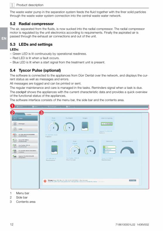
The waste water pump in the separation system feeds the fluid together with the finer solid particles through the waste water system connection into the central waste water network�
5.2 RadialcompressorThe air, separated from the fluids, is now sucked into the radial compressor� The radial compressor motor is regulated by the unit electronics according to requirements� Finally the aspirated air is passed through the exhaust air connections and out of the unit�
5.3 LEDsandsettingsLEDs: – Green LED is lit continuously by operational readiness� – Red LED is lit when a fault occurs� – Blue LED is lit when a start signal from the treatment unit is present�
5.4 TyscorPulse(optional)The software is connected to the appliances from Dürr Dental over the network, and displays the cur-rent status as well as messages and errors�All messages are logged and can be printed or sent�The regular maintenance and care is managed in the tasks� Reminders signal when a task is due� The cockpit shows the appliances with the current characteristic data and provides a quick overview of the functional status of the appliances�The software interface consists of the menu bar, the side bar and the contents area�
1
2 3
1 Menu bar2 Side bar3 Contents area
EN
7186100001L02 1406V002 13
Product description
The contents area depends on the tab selected on the side bar� The current messages are always displayed in the lower part of the contents area�
The views and rights depend on the selected access level (operator, administrator or service technician)�
While the software is running (even if the software window is closed), the access level is visible in the task bar� The symbol shows the current status of the appliances� If a new message appears, a speech bubble tip also appears�
EN
14 7186100001L02 1406V002
6.3 PlumbingmaterialsOnlyusevacuum-sealedHT-wastepipesmanufacturedfromthefollowingplumbingmaterials: – Polypropylene (PP, Polypropen), – chlorinated polyvinyl chloride (PVC-C), – unplasticised polyvinyl chloride (PVC-U), – polyethylene (PEh)�
Thefollowinghosematerialsmaynotbeused: – acrylonitrile-butadiene-styrene copolymer (ABS),
– Styrene copolymer blends (e�g� SAN + PVC)�
6.4 HosematerialsForwasteconnectionsandsuctionlinesonlyusethefollowinghosetypes: – flexible spiral hoses of PVC with integrated spiral or equivalent hoses
– hoses of a material which is resistant to the dental disinfectants and chemicals
Hoses of plastic undergo an ageing process� Therefore, they should be in-spected regularly and replaced as nec-essary�
Thefollowinghosematerialsmaynotbeused:
– rubber hoses – completely PVC hoses – hoses which are not sufficiently flexible
6.5 Notesonelectricalconnections
• Ensure that electrical connections to the mains power supply are carried out according to current valid national and local regulations and standards governing the installation of low voltage units in medical facilities�
• Heed the current consumption of the appli-ances to be connected�
6 PrerequisitesThe unit can be installed on the same level as the surgery room or in a floor below�
Further information can be found in our suction planning information leaflet� Or-der number 9000-617-03/��
6.1 AreaofinstallationThe room chosen for set up must satisfy the fol-lowing criteria: – Closed, dry, well-ventilated room – No purpose-built room (e� g� boiler room or wet room)
– Corresponding ambient conditions� "4 Technical data"
– Do not set up within the vicinity of the patientsTake environmental and ambient condi-tions into account� Do not operate the unit in damp or wet conditions�
– When installing in a cabinet then inlet and outlet ventilation slots must be present, free cross section of at least 120 cm2�
– Where there is the possibility of the recom-mended room air temperature being exceed-ed then additional ventilation (fan) must be provided� The air flow performance must be at least 2 m3/min�
– Do not cover cooling slots or openings and ensure adequate distance for sufficient cool-ing�
– Mains cable plug connections freely acces-sible so they can be quickly disconnected if there is any danger�
6.2 Set-upalternativesWhen setting up the unit the following alterna-tives are available: – Wall installation using the Dürr Dental wall mounting
– In a ventilated cabinet – In the Dürr Dental noise reducing housing
Mounting
EN
7186100001L02 1406V002 15
Mounting
7 SystemcomponentsThe following list contains system components required or recommended for various proce-dures or for installation�
7.1 RinsingunitIt is recommended that the suction system is equipped with a rinsing unit, e�g� fitted in the treatment unit� The rinsing unit provides a small amount of water during aspiration� The aspirat-ed fluids (blood, saliva, rinsing water etc�) is thereby diluted and can be transported more ef-fectively�For further information refer to the rinsing unit installation and operating instructions
7.2 ExhaustairfilterWe strongly recommend the installation of an exhaust air filter in the exhaust air system for hy-gienic reasons�If the suction unit is installed in the surgery and the exhaust air is not directed to the outside, it is essential to install an exhaust air filter�Depending on the version and condition of the exhaust air filter, it must be replaced after 1-2 years at the latest�
The integrated separation unit within the suction unit does not hold bacteria back, which is why it is strongly recom-mended to install a suitable filter into the exhaust air system�
7.3 NoisereducerWhere the noise level from the exhaust air vent or the flow noise generated is too high, then a noise reducer can be installed in the exhaust air connections�
7.4 SurgetankThe combination of a suction unit together with an amalgam separator requires the installation of a surge tank� The surge tank reduces pres-sure peaks caused by the suction unit's waste water pump and acts as a buffer against tempo-rary rises in the volume of water�The surge tank can also be used to supply the waste water directly into the building waste wa-ter system� In this case the suction unit waste water is diverted to the building drainage system under zero pressure�
6.6 Notesonconnectionlines
MainslineOnly use the mains connected cable provided for connecting the appliance�
controlline
Typeoflayout Lineproperties(mini-mumrequirements)
fixed – Shielded light plastic-sheathed cable (e�g� (N)YM (St)-J)
flexible – PVC data cable with sheathing as used for data and IT (e�g� LiYCY)
or – Light-PVC-control line with sheathed cable
EN
16 7186100001L02 1406V002
Mounting
7.5 FlowacceleratorIn order that the suction system is kept free of deposits, then a flow accelerator in combination with the spittoon valve can be fitted� When us-ing a bowl rinse system then water can collect before the flow accelerator� The next time suc-tion takes place using the large cannula this fluid which has been collected is flushed with great force and high speed through the suction sys-tem� This ensures automatic cleaning of the suction connections�
EN
7186100001L02 1406V002 17
Mounting
8 Installation
The actual connection can vary according to the set up method chosen� The connection shown is only an example�
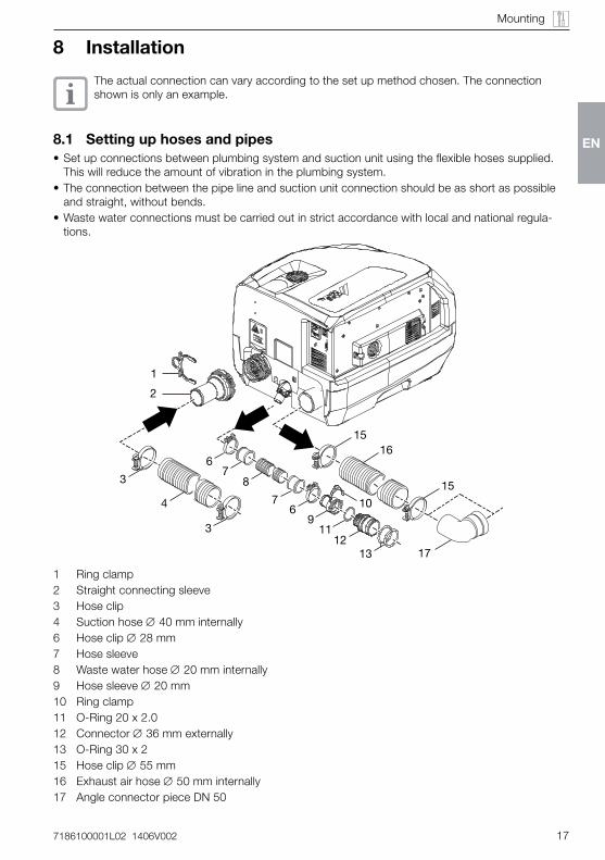
8.1 Settinguphosesandpipes• Set up connections between plumbing system and suction unit using the flexible hoses supplied�
This will reduce the amount of vibration in the plumbing system�• The connection between the pipe line and suction unit connection should be as short as possible
and straight, without bends�• Waste water connections must be carried out in strict accordance with local and national regula-
tions�
67
8
4
3
2
1312
11
76
910
1
3
15
15
16
17
1 Ring clamp2 Straight connecting sleeve3 Hose clip4 Suction hose ∅ 40 mm internally6 Hose clip ∅ 28 mm7 Hose sleeve8 Waste water hose ∅ 20 mm internally9 Hose sleeve ∅ 20 mm10 Ring clamp11 O-Ring 20 x 2�012 Connector ∅ 36 mm externally13 O-Ring 30 x 215 Hose clip ∅ 55 mm16 Exhaust air hose ∅ 50 mm internally17 Angle connector piece DN 50
EN
18 7186100001L02 1406V002
Mounting
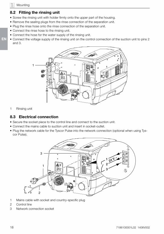
8.2 Fittingtherinsingunit• Screw the rinsing unit with holder firmly onto the upper part of the housing�• Remove the sealing plugs from the rinse connection of the separation unit�• Plug the rinse hose onto the rinse connection of the separation unit�• Connect the rinse hose to the rinsing unit�• Connect the hose for the water supply of the rinsing unit�• Connect the voltage supply of the rinsing unit on the control connection of the suction unit to pins 2
and 3�
1
2
3
1 Rinsing unit
8.3 Electricalconnection• Secure the socket piece to the control line and connect to the suction unit�• Connect the mains cable to suction unit and insert in socket-outlet�• Plug the network cable for the Tyscor Pulse into the network connection (optional when using Tys-
cor Pulse)�
1
3
24 V ~1
2
31
2
3
1 Mains cable with socket and country-specific plug2 Control line3 Network connection socket
EN
7186100001L02 1406V002 19
Mounting
8.4 PCBelectricalconnections
PENL
X5
X15
X11 X9
X7
X6
X10
E1 +
H12
H14
X12
X13
X1
X2
S
X3
H1
H2H3H4H5
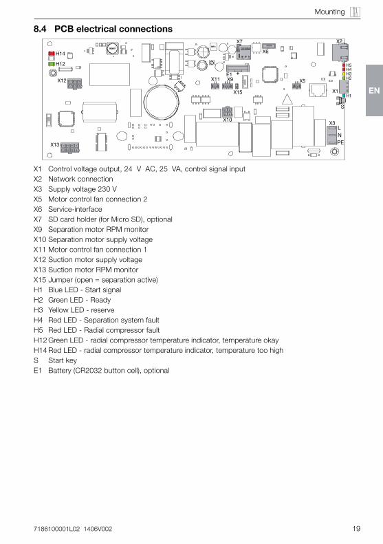
X1 Control voltage output, 24 V AC, 25 VA, control signal inputX2 Network connectionX3 Supply voltage 230 VX5 Motor control fan connection 2X6 Service-interfaceX7 SD card holder (for Micro SD), optionalX9 Separation motor RPM monitorX10 Separation motor supply voltageX11 Motor control fan connection 1X12 Suction motor supply voltageX13 Suction motor RPM monitorX15 Jumper (open = separation active)H1 Blue LED - Start signalH2 Green LED - ReadyH3 Yellow LED - reserveH4 Red LED - Separation system faultH5 Red LED - Radial compressor faultH12 Green LED - radial compressor temperature indicator, temperature okayH14 Red LED - radial compressor temperature indicator, temperature too highS Start keyE1 Battery (CR2032 button cell), optional
EN
20 7186100001L02 1406V002
Mounting
Prerequisite:
9 The appliance is switched on and connected with the network
9 Administrator or service technician access level selected in the software
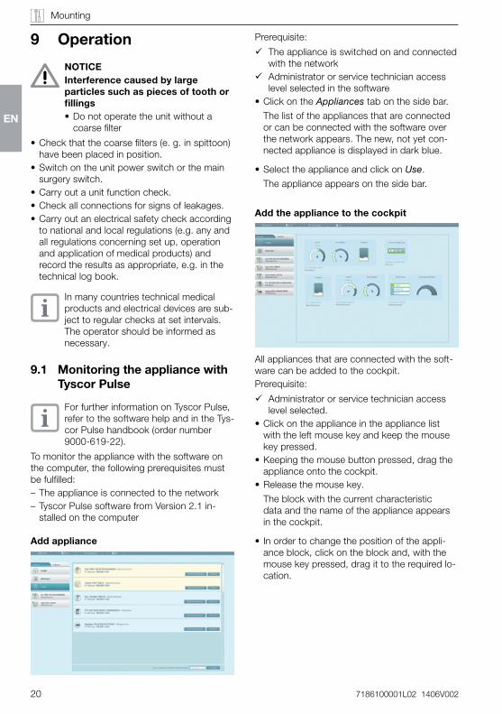
• Click on the Appliances tab on the side bar�
The list of the appliances that are connected or can be connected with the software over the network appears� The new, not yet con-nected appliance is displayed in dark blue�
• Select the appliance and click on Use�
The appliance appears on the side bar�
Addtheappliancetothecockpit
All appliances that are connected with the soft-ware can be added to the cockpit� Prerequisite:
9 Administrator or service technician access level selected�
• Click on the appliance in the appliance list with the left mouse key and keep the mouse key pressed�
• Keeping the mouse button pressed, drag the appliance onto the cockpit�
• Release the mouse key�
The block with the current characteristic data and the name of the appliance appears in the cockpit�
• In order to change the position of the appli-ance block, click on the block and, with the mouse key pressed, drag it to the required lo-cation�
9 Operation
NOTICEInterferencecausedbylargeparticlessuchaspiecesoftoothorfillings• Do not operate the unit without a
coarse filter
• Check that the coarse filters (e� g� in spittoon) have been placed in position�
• Switch on the unit power switch or the main surgery switch�
• Carry out a unit function check�• Check all connections for signs of leakages�• Carry out an electrical safety check according
to national and local regulations (e�g� any and all regulations concerning set up, operation and application of medical products) and record the results as appropriate, e�g� in the technical log book�
In many countries technical medical products and electrical devices are sub-ject to regular checks at set intervals� The operator should be informed as necessary�
9.1 MonitoringtheappliancewithTyscorPulse
For further information on Tyscor Pulse, refer to the software help and in the Tys-cor Pulse handbook (order number 9000-619-22)�
To monitor the appliance with the software on the computer, the following prerequisites must be fulfilled: – The appliance is connected to the network – Tyscor Pulse software from Version 2�1 in-stalled on the computer
Addappliance
EN
7186100001L02 1406V002 21
Mounting
Transferthemaintenancescheduleintothesoftware
It is recommended to transfer the tasks from the maintenance schedule (see "13 Maintenance") into the maintenance schedule of the software� • Select the Tasks view in the software�• Add task�Result:The task appears on the side bar and in the maintenance schedule�
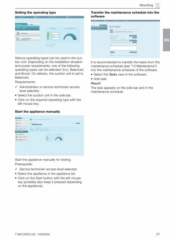
Settingtheoperatingtype
Various operating types can be used in the suc-tion unit� Depending on the installation situation and power requirements, one of the following operating types can be selected: Eco, Balanced and Boost� On delivery, the suction unit is set to Balanced�Requirements:
9 Administrator or service technician access level selected�
• Select the suction unit in the side bar�• Click on the required operating type with the
left mouse key�
Starttheappliancemanually
Start the appliance manually for testing�Prerequisite:
9 Service technician access level selected�• Select the appliance in the appliance list�• Click on the Start button with the left mouse
key (possibly also keep it pressed depending on the appliance)�
EN
22 7186100001L02 1406V002
11 MonitoringtheappliancewithTyscorPulse
For further information on Tyscor Pulse, refer to the software help and in the Tys-cor Pulse handbook (order number 9000-619-22)�
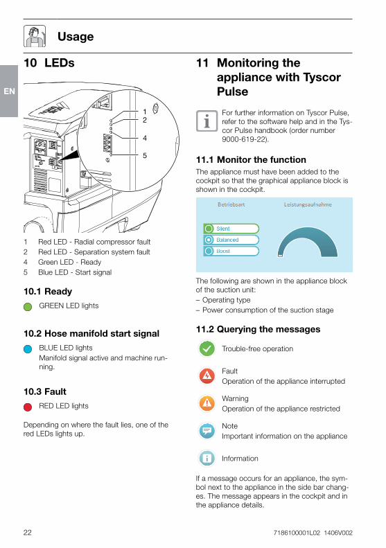
11.1MonitorthefunctionThe appliance must have been added to the cockpit so that the graphical appliance block is shown in the cockpit�
The following are shown in the appliance block of the suction unit: – Operating type – Power consumption of the suction stage
11.2Queryingthemessages
Trouble-free operation
FaultOperation of the appliance interrupted
WarningOperation of the appliance restricted
NoteImportant information on the appliance
Information
If a message occurs for an appliance, the sym-bol next to the appliance in the side bar chang-es� The message appears in the cockpit and in the appliance details�
10 LEDs
12
4
5
1 Red LED - Radial compressor fault2 Red LED - Separation system fault4 Green LED - Ready5 Blue LED - Start signal
10.1ReadyGREEN LED lights
10.2HosemanifoldstartsignalBLUE LED lightsManifold signal active and machine run-ning�
10.3FaultRED LED lights
Depending on where the fault lies, one of the red LEDs lights up�
Usage
EN
7186100001L02 1406V002 23
Usage
12 Disinfectionandcleaning
NOTICEUnitinterferenceordamagebyus-ingincorrectagentsThis will lead to loss of any claims under the guarantee�• Do not use any foaming agent, e�g�
household cleaning agent or instru-ment disinfection agent�
• Do not use abrasive cleaners�• Do not use agents containing chlo-
rine�• Do not use any sort of solvent such
as acetone�
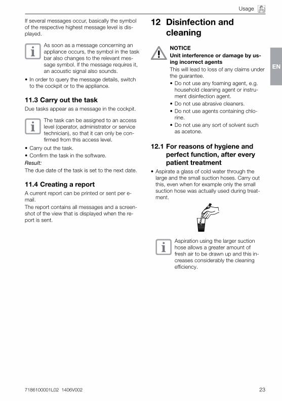
12.1Forreasonsofhygieneandperfectfunction,aftereverypatienttreatment
• Aspirate a glass of cold water through the large and the small suction hoses� Carry out this, even when for example only the small suction hose was actually used during treat-ment�
Aspiration using the larger suction hose allows a greater amount of fresh air to be drawn up and this in-creases considerably the cleaning efficiency�
If several messages occur, basically the symbol of the respective highest message level is dis-played�
As soon as a message concerning an appliance occurs, the symbol in the task bar also changes to the relevant mes-sage symbol� If the message requires it, an acoustic signal also sounds�
• In order to query the message details, switch to the cockpit or to the appliance�
11.3CarryoutthetaskDue tasks appear as a message in the cockpit�
The task can be assigned to an access level (operator, administrator or service technician), so that it can only be con-firmed from this access level�
• Carry out the task�• Confirm the task in the software�Result:The due date of the task is set to the next date�
11.4CreatingareportA current report can be printed or sent per e-mail�The report contains all messages and a screen-shot of the view that is displayed when the re-port is sent�
EN
24 7186100001L02 1406V002
Usage
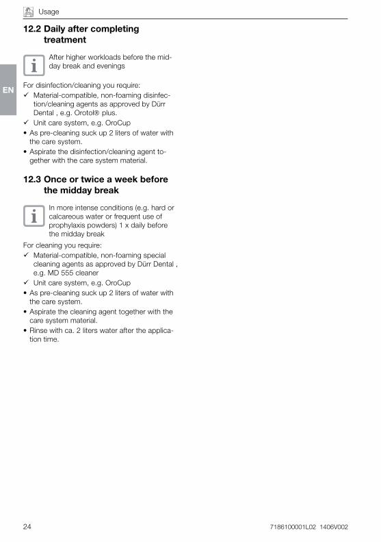
12.2Dailyaftercompletingtreatment
After higher workloads before the mid-day break and evenings
For disinfection/cleaning you require: 9 Material-compatible, non-foaming disinfec-
tion/cleaning agents as approved by Dürr Dental , e�g� Orotol plus�
9 Unit care system, e�g� OroCup• As pre-cleaning suck up 2 liters of water with
the care system�• Aspirate the disinfection/cleaning agent to-
gether with the care system material�
12.3Onceortwiceaweekbeforethemiddaybreak
In more intense conditions (e�g� hard or calcareous water or frequent use of prophylaxis powders) 1 x daily before the midday break
For cleaning you require: 9 Material-compatible, non-foaming special
cleaning agents as approved by Dürr Dental , e�g� MD 555 cleaner
9 Unit care system, e�g� OroCup• As pre-cleaning suck up 2 liters of water with
the care system�• Aspirate the cleaning agent together with the
care system material�• Rinse with ca� 2 liters water after the applica-
tion time�
EN
7186100001L02 1406V002 25
Usage
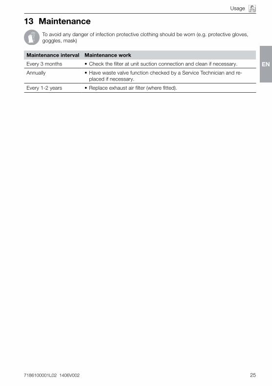
13 MaintenanceTo avoid any danger of infection protective clothing should be worn (e�g� protective gloves, goggles, mask)
Maintenanceinterval Maintenancework
Every 3 months • Check the filter at unit suction connection and clean if necessary�
Annually • Have waste valve function checked by a Service Technician and re-placed if necessary�
Every 1-2 years • Replace exhaust air filter (where fitted)�
EN
26 7186100001L02 1406V002
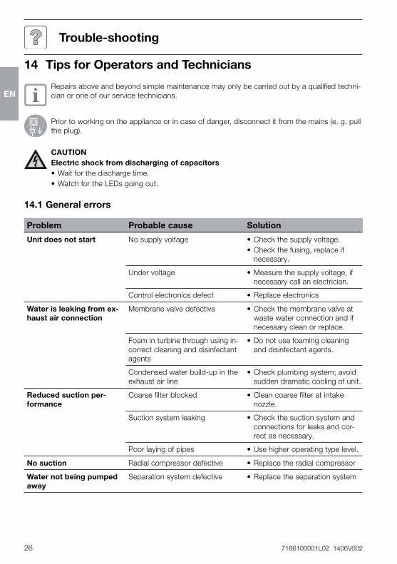
14 TipsforOperatorsandTechnicians
Repairs above and beyond simple maintenance may only be carried out by a qualified techni-cian or one of our service technicians�
Prior to working on the appliance or in case of danger, disconnect it from the mains (e� g� pull the plug)�
CAUTIONElectricshockfromdischargingofcapacitors• Wait for the discharge time�• Watch for the LEDs going out�
14.1Generalerrors
Problem Probablecause Solution
Unitdoesnotstart No supply voltage • Check the supply voltage�• Check the fusing, replace if
necessary�
Under voltage • Measure the supply voltage, if necessary call an electrician�
Control electronics defect • Replace electronics
Waterisleakingfromex-haustairconnection
Membrane valve defective • Check the membrane valve at waste water connection and if necessary clean or replace�
Foam in turbine through using in-correct cleaning and disinfectant agents
• Do not use foaming cleaning and disinfectant agents�
Condensed water build-up in the exhaust air line
• Check plumbing system; avoid sudden dramatic cooling of unit�
Reducedsuctionper-formance
Coarse filter blocked • Clean coarse filter at intake nozzle�
Suction system leaking • Check the suction system and connections for leaks and cor-rect as necessary�
Poor laying of pipes • Use higher operating type level�
Nosuction Radial compressor defective • Replace the radial compressor
Waternotbeingpumpedaway
Separation system defective • Replace the separation system
Trouble-shooting
EN
7186100001L02 1406V002 27
Trouble-shooting
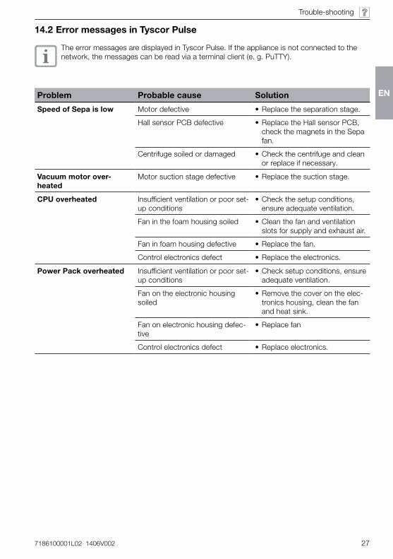
14.2ErrormessagesinTyscorPulse
The error messages are displayed in Tyscor Pulse� If the appliance is not connected to the network, the messages can be read via a terminal client (e� g� PuTTY)�
Problem Probablecause Solution
SpeedofSepaislow Motor defective • Replace the separation stage�
Hall sensor PCB defective • Replace the Hall sensor PCB, check the magnets in the Sepa fan�
Centrifuge soiled or damaged • Check the centrifuge and clean or replace if necessary�
Vacuummotorover-heated
Motor suction stage defective • Replace the suction stage�
CPUoverheated Insufficient ventilation or poor set-up conditions
• Check the setup conditions, ensure adequate ventilation�
Fan in the foam housing soiled • Clean the fan and ventilation slots for supply and exhaust air�
Fan in foam housing defective • Replace the fan�
Control electronics defect • Replace the electronics�
PowerPackoverheated Insufficient ventilation or poor set-up conditions
• Check setup conditions, ensure adequate ventilation�
Fan on the electronic housing soiled
• Remove the cover on the elec-tronics housing, clean the fan and heat sink�
Fan on electronic housing defec-tive
• Replace fan
Control electronics defect • Replace electronics�
EN
28 7186100001L02 1406V002
Trouble-shooting
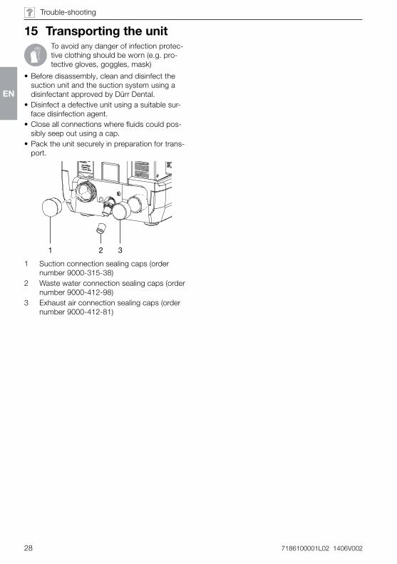
15 TransportingtheunitTo avoid any danger of infection protec-tive clothing should be worn (e�g� pro-tective gloves, goggles, mask)
• Before disassembly, clean and disinfect the suction unit and the suction system using a disinfectant approved by Dürr Dental�
• Disinfect a defective unit using a suitable sur-face disinfection agent�
• Close all connections where fluids could pos-sibly seep out using a cap�
• Pack the unit securely in preparation for trans-port�
21 3
1 Suction connection sealing caps (order number 9000-315-38)
2 Waste water connection sealing caps (order number 9000-412-98)
3 Exhaust air connection sealing caps (order number 9000-412-81)
EN
7186100001L02 1406V002 29
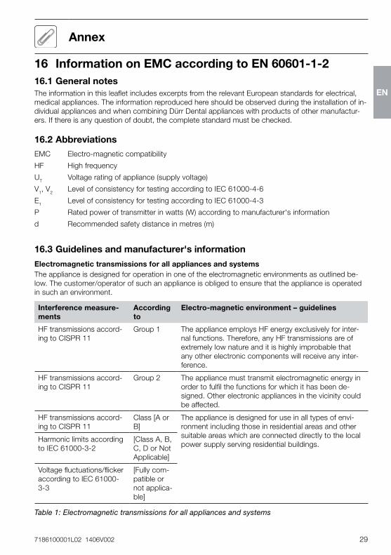
16 InformationonEMCaccordingtoEN 60601-1-216.1GeneralnotesThe information in this leaflet includes excerpts from the relevant European standards for electrical, medical appliances� The information reproduced here should be observed during the installation of in-dividual appliances and when combining Dürr Dental appliances with products of other manufactur-ers� If there is any question of doubt, the complete standard must be checked�
16.2AbbreviationsEMC Electro-magnetic compatibility
HF High frequency
UT Voltage rating of appliance (supply voltage)
V1, V2 Level of consistency for testing according to IEC 61000-4-6
E1 Level of consistency for testing according to IEC 61000-4-3
P Rated power of transmitter in watts (W) according to manufacturer's information
d Recommended safety distance in metres (m)
16.3Guidelinesandmanufacturer'sinformation
ElectromagnetictransmissionsforallappliancesandsystemsThe appliance is designed for operation in one of the electromagnetic environments as outlined be-low� The customer/operator of such an appliance is obliged to ensure that the appliance is operated in such an environment�
Interferencemeasure-ments
Accordingto
Electro-magneticenvironment–guidelines
HF transmissions accord-ing to CISPR 11
Group 1 The appliance employs HF energy exclusively for inter-nal functions� Therefore, any HF transmissions are of extremely low nature and it is highly improbable that any other electronic components will receive any inter-ference�
HF transmissions accord-ing to CISPR 11
Group 2 The appliance must transmit electromagnetic energy in order to fulfil the functions for which it has been de-signed� Other electronic appliances in the vicinity could be affected�
HF transmissions accord-ing to CISPR 11
Class [A or B]
The appliance is designed for use in all types of envi-ronment including those in residential areas and other suitable areas which are connected directly to the local power supply serving residential buildings�
Harmonic limits according to IEC 61000-3-2
[Class A, B, C, D or Not Applicable]
Voltage fluctuations/flicker according to IEC 61000-3-3
[Fully com-patible or not applica-ble]
Table 1: Electromagnetic transmissions for all appliances and systems
Annex
EN
30 7186100001L02 1406V002
Annex
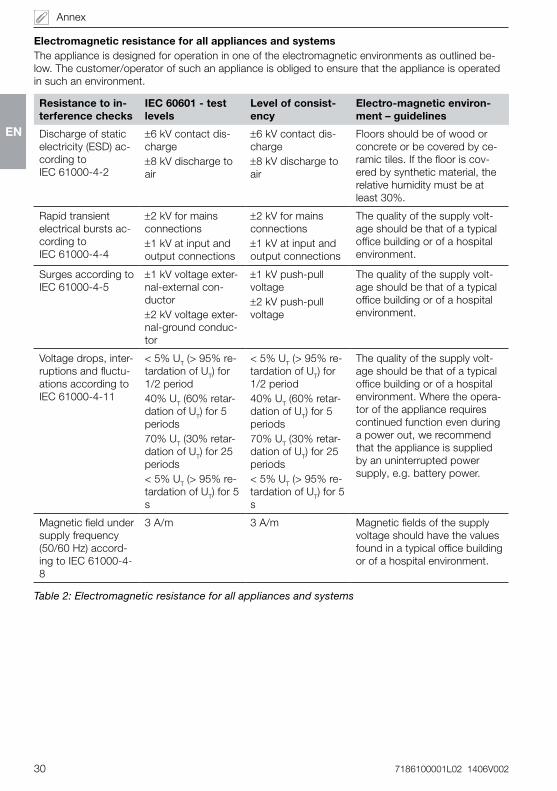
ElectromagneticresistanceforallappliancesandsystemsThe appliance is designed for operation in one of the electromagnetic environments as outlined be-low� The customer/operator of such an appliance is obliged to ensure that the appliance is operated in such an environment�
Resistancetoin-terferencechecks
IEC60601-testlevels
Levelofconsist-ency
Electro-magneticenviron-ment–guidelines
Discharge of static electricity (ESD) ac-cording to IEC 61000-4-2
±6 kV contact dis-charge±8 kV discharge to air
±6 kV contact dis-charge±8 kV discharge to air
Floors should be of wood or concrete or be covered by ce-ramic tiles� If the floor is cov-ered by synthetic material, the relative humidity must be at least 30%�
Rapid transient electrical bursts ac-cording to IEC 61000-4-4
±2 kV for mains connections±1 kV at input and output connections
±2 kV for mains connections±1 kV at input and output connections
The quality of the supply volt-age should be that of a typical office building or of a hospital environment�
Surges according to IEC 61000-4-5
±1 kV voltage exter-nal-external con-ductor±2 kV voltage exter-nal-ground conduc-tor
±1 kV push-pull voltage±2 kV push-pull voltage
The quality of the supply volt-age should be that of a typical office building or of a hospital environment�
Voltage drops, inter-ruptions and fluctu-ations according to IEC 61000-4-11
< 5% UT (> 95% re-tardation of UT) for 1/2 period40% UT (60% retar-dation of UT) for 5 periods70% UT (30% retar-dation of UT) for 25 periods< 5% UT (> 95% re-tardation of UT) for 5 s
< 5% UT (> 95% re-tardation of UT) for 1/2 period40% UT (60% retar-dation of UT) for 5 periods70% UT (30% retar-dation of UT) for 25 periods< 5% UT (> 95% re-tardation of UT) for 5 s
The quality of the supply volt-age should be that of a typical office building or of a hospital environment� Where the opera-tor of the appliance requires continued function even during a power out, we recommend that the appliance is supplied by an uninterrupted power supply, e�g� battery power�
Magnetic field under supply frequency (50/60 Hz) accord-ing to IEC 61000-4-8
3 A/m 3 A/m Magnetic fields of the supply voltage should have the values found in a typical office building or of a hospital environment�
Table 2: Electromagnetic resistance for all appliances and systems
EN
7186100001L02 1406V002 31
Annex
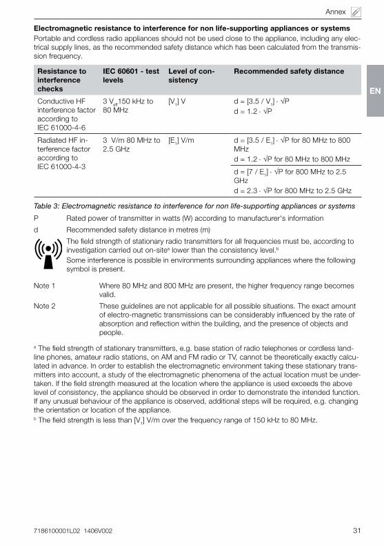
Electromagneticresistancetointerferencefornonlife-supportingappliancesorsystemsPortable and cordless radio appliances should not be used close to the appliance, including any elec-trical supply lines, as the recommended safety distance which has been calculated from the transmis-sion frequency�
Resistancetointerferencechecks
IEC60601-testlevels
Levelofcon-sistency
Recommendedsafetydistance
Conductive HF interference factor according to IEC 61000-4-6
3 Veff150 kHz to 80 MHz
[V1] V d = [3�5 / V1] ⋅ √Pd = 1�2 ⋅ √P
Radiated HF in-terference factor according to IEC 61000-4-3
3 V/m 80 MHz to 2�5 GHz
[E1] V/m d = [3�5 / E1] ⋅ √P for 80 MHz to 800 MHzd = 1�2 ⋅ √P for 80 MHz to 800 MHz
d = [7 / E1] ⋅ √P for 800 MHz to 2�5 GHzd = 2�3 ⋅ √P for 800 MHz to 2�5 GHz
Table 3: Electromagnetic resistance to interference for non life-supporting appliances or systems
P Rated power of transmitter in watts (W) according to manufacturer's information
d Recommended safety distance in metres (m)
The field strength of stationary radio transmitters for all frequencies must be, according to investigation carried out on-sitea lower than the consistency level�b
Some interference is possible in environments surrounding appliances where the following symbol is present�
Note 1 Where 80 MHz and 800 MHz are present, the higher frequency range becomes valid�
Note 2 These guidelines are not applicable for all possible situations� The exact amount of electro-magnetic transmissions can be considerably influenced by the rate of absorption and reflection within the building, and the presence of objects and people�
a The field strength of stationary transmitters, e�g� base station of radio telephones or cordless land-line phones, amateur radio stations, on AM and FM radio or TV, cannot be theoretically exactly calcu-lated in advance� In order to establish the electromagnetic environment taking these stationary trans-mitters into account, a study of the electromagnetic phenomena of the actual location must be under-taken� If the field strength measured at the location where the appliance is used exceeds the above level of consistency, the appliance should be observed in order to demonstrate the intended function� If any unusual behaviour of the appliance is observed, additional steps will be required, e�g� changing the orientation or location of the appliance�b The field strength is less than [V1] V/m over the frequency range of 150 kHz to 80 MHz�
EN
32 7186100001L02 1406V002
Annex
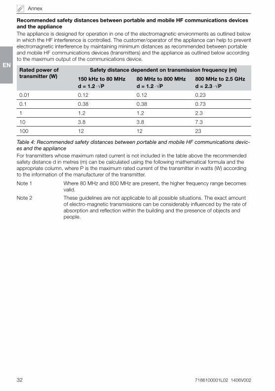
RecommendedsafetydistancesbetweenportableandmobileHFcommunicationsdevicesandtheapplianceThe appliance is designed for operation in one of the electromagnetic environments as outlined below in which the HF interference is controlled� The customer/operator of the appliance can help to prevent electromagnetic interference by maintaining minimum distances as recommended between portable and mobile HF communications devices (transmitters) and the appliance as outlined below according to the maximum output of the communications device�
Ratedpoweroftransmitter(W)
Safetydistancedependentontransmissionfrequency(m)
150 kHzto80 MHzd=1.2⋅√P
80 MHzto800 MHzd=1.2⋅√P
800 MHzto2.5 GHzd=2.3⋅√P
0�01 0�12 0�12 0�23
0�1 0�38 0�38 0�73
1 1�2 1�2 2�3
10 3�8 3�8 7�3
100 12 12 23
Table 4: Recommended safety distances between portable and mobile HF communications devic-es and the applianceFor transmitters whose maximum rated current is not included in the table above the recommended safety distance d in metres (m) can be calculated using the following mathematical formula and the appropriate column, where P is the maximum rated current of the transmitter in watts (W) according to the information of the manufacturer of the transmitter�
Note 1 Where 80 MHz and 800 MHz are present, the higher frequency range becomes valid�
Note 2 These guidelines are not applicable to all possible situations� The exact amount of electro-magnetic transmissions can be considerably influenced by the rate of absorption and reflection within the building and the presence of objects and people�
EN
7186100001L02 1406V002 33
Annex
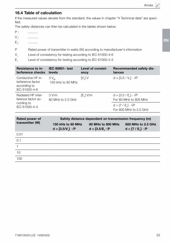
16.4TableofcalculationIf the measured values deviate from the standard, the values in chapter "4 Technical data" are speci-fied�The safety distances can then be calculated in the tables shown below�
P : ����������
V1: ����������
E1: ����������
P Rated power of transmitter in watts (W) according to manufacturer's information
V1 Level of consistency for testing according to IEC 61000-4-6
E1 Level of consistency for testing according to IEC 61000-4-3
Resistancetoin-terferencechecks
IEC60601-testlevels
Levelofconsist-ency
Recommendedsafetydis-tances
Conductive HF in-terference factor according to IEC 61000-4-6
3 Veff
150 kHz to 80 MHz[V1] V d = [3�5 / V1] ⋅ √P
Radiated HF inter-ference factor ac-cording to IEC 61000-4-3
3 V/m80 MHz to 2�5 GHz
[E1] V/m d = [3�5 / E1] ⋅ √P For 80 MHz to 800 MHz
d = [7 / E1] ⋅ √P For 800 MHz to 2�5 GHz
Ratedpoweroftransmitter(W)
Safetydistancedependentontransmissionfrequency(m)
150 kHzto80 MHzd=[3.5/V1]⋅√P
80 MHzto800 MHzd=[3.5/E1⋅√P
800 MHzto2.5 GHzd=[7/E1]⋅√P
0�01
0�1
1
10
100
EN


Dürr Dental aGHöpfigheimer Strasse 17 74321 Bietigheim-BissingenGermanyFon: +49 7142 [email protected]