u eeeiiiiiiii soil-structure interaction and … · r technical report k".w list of soils,...
TRANSCRIPT

'W AD-Al03 384 ARMY ENGINEER WATERWAYS EXPERIMENT STATION VICKSBURG MS F/G 13/13LIST OF SOILS, SOIL-STRUCTURE INTERACTION AND OTHER RELATED COM--ETC(U)MAY 81 N RADHAKRISHNAN, P K SENTERUNCLASSIFIED WES-TR-K-81-1 NL
U EEEIIIIIIIIEIIEEEIIIEEEI
mmmhhmmhhl -

r
TECHNICAL REPORT K".W
LIST OF SOILS, SOIL-STRUCTURE INTERACTION__ AND OTHER RELATED COMPUTER PROGRAMS
, -AVAILABLE FOR LMVD ENGINEERSCompiled byk N. Radhakrishnan and Paul K. Sonter
Automatic Data Processing CenterU. S. Army Engineer Waterways Expesment StationP. 0. Box 631, Victsburg, Miss. 39180DI
may 1981 AUG 26 18I Final Report5 I Aw fl d F o Pub c R Q ~'u. Wh " tltM U ft "- A
I7
Flowered hr U. S. Army Engineer Division, Lower Misslsippi ValleyP.O. Box 80, Vicksburg, Miss. 39180
81 8 26 018

Destroy this report when no longer needed. Do not returnit to the originator.
The findings in this report are not to be construed as an officialDepartment of the Army position unless so designated.
by other authorized documents.
The contents of this report are not to be used foradvertising, publication, or promotional purposes.Citation of trade names does not constitute anofficial endorsement or approval of the use of
such commercial products.
LI A-

UnclassifiedSECURITY CLASSIFICATION OF THIeS PAGE f1Ther Data fft,IrRADINTRCTON
OTE PAE CUE R PROGAMS AVAILARL FORETNFR
U.. -R P R ArMBE ng n e Di i i n Lo e Mi s s p May , "8AG71. 0.t Box, 80 fikbug Miss 39180 CCSINNO .RCIIN' GNME
JIT FsaRUTRE; TEACIN ia. ElA realICAIN ONRDN
1.1416. GIT IINESE MENT B.f
tON RAC OReRANort)E~
I K SUPEMNAY OE
CmEputerK programs
Auoma-ticDtarocss ienter
othe Srlte compuer prison ogasaalbefrniersoth Lwer MississippiMy0IValley Diviion Program for usPntefloigsbetAESrlitd
taton seNT tlement Y and conso~lidartfom toln e Offite data SEITrumenAS.(ftin andrt
/ 52D T ON N V O IS O S L T UnclassifiedZEURT CLS1 I&CION IA O NI DOS AG WNGRDeIGa
SCHEDUL
16. 0.............T.T.M.N..(of.this.Report

SECURITY CLASSIFICATION OF THIS PAGE(WhaDaEi
SECURITY CLASSIFICATION OF THIS PAGEII%.n Dae Entored)

PREFACE
This report presents a list of computer programs compiled at the
U. S. Army Engineer Waterways Experiment Station (WES) as part of the
normal operation of the joint WES and U. S. Army Engineer Division,
Lower Mississippi Valley (LMVD), Computer Center for fiscal years 1980
and 1981.
The list was compiled and this report prepared by Dr. N. Radha-
krishnan and Mr. Paul K. Senter, Automatic Data Processing (ADP) Center,
based on input received from the LMVD Districts and from the WES labora-
tories. Gratitude is expressed to these offices for their cooperation
in the effort. LMVD technical contact for this work was Mr. Tony Young,
Geology, Soils and Materials Branch. Mr. Donald L. Neumann was Chief
of the ADP Center during the performance of the work.
Director of WES during the period of the work was COL N. P.
Conover, CE. Technical Director was Mr. F. R. Brown.
d
I T
1,i
.*
Pf

---- BMW
CONTENTS
Page
PREFACE. .. ............................. 1
PART 1: INTRODUCTION .. ............... ....... 3
History of Program List. ................. 3Subject Groupings. ................. ... 3Abstracts. ............... ......... 4Abbreviations. ................ ...... 4Additional Informat ion .. .................. 4
PART II: LIST OF AVAILABLE PROGRAMS .. ............... 64
1. T-Walls .. ................. ..... 72. Slope Stability .. ............... ... 83. Piles, Sheet Piles & Cells .. ........... 154. Seepage. .. ..................... 265. Stress Computation, Settlement, & Consolidation .- 286. Piezometer Data. .. ................ 317. Instrumentation & Laboratory Data. .. ....... 348. Plotting Programs. .. ............... 449. Finite Element Method/Finite Difference. .. .... 47
10. Earthquakes & Dynamics .. ............. 5211. Others .. ...................... 54
PART III: ABSTRACTS .. ....................... 55
1. T-Walls. .. ..................... 562. Slope Stability. .. ................. 583. Piles, Sheet Piles & Cells .. ........... 734. Seepage ............... ........ .... 1045. Stress Computation, Settlement, & Consolidation .10
6. Piezometer Data .. .................. 1147. Instrumentation & Laboratory Data .. ........ 1258. Plotting Programs .. ................ 1289. Finite Element Method/Finite Difference .. ..... 131
10. Earthquakes & Dynamics. .............. 145
2
.. chi&.

LIST OF SOILS, SOIL-STRUCTURE INTERACTION,
AND OTHER RELATED COMPUTER PROGRAMS
AVAILABLE FOR LMVD ENGINEERS
PART I: INTRODUCTION
History of Program List
1. In June 1975, the Automatic Data Processing (ADP) Center ofthe U. S. Army Engineer Waterways Experiment Station (WES) published for
the U. S. Army Engineer Division, Lower Mississippi Valley (LMVD), a
list of soils, structures, soil-structure interaction, and other related
computer programs available for LMVD engineers. In February 1978, a
more comprehensive list of available structures programs was published
as WES Technical Report K-78-1, "List of Computer Programs for Computer-
Aided Structural Engineering." During the 5 years since the original
list of soils programs was introduced, a number of other useful programs
have become available. This is especially true in the case of programs
with computer graphics capabilities, which have become more prevalent
in the Corps. It has also become evident that some of the programs
need to be deleted from the original list.
2. This new list is the product of omitting the structures pro-
grams and updating and rearranging the original list. As an additional
feature, abstracts of some of the listed programs are included in Part
III of this report.
Subject Groupings
3. The programs have been grouped under the following subject
groupings in Part II of this report:
1. T-Walls2. Slope Stability3. Piles, Sheet Piles & Cells4. Seepage5. Stress Computation, Settlement, & Consolidation
3
*...-

6. Piezometer Data7. Instrumentation & Laboratory Data8. Plotting Programs9. Finite Element Method/Finite Difference
10. Earthquakes & Dynamics11. Others
Abstracts
4. The computer program abstracts that are included in Part III
are arranged by the same subject groupings.
Abbreviations
5. Abbreviations of computer systems or equipment used in this
report are defined as follows:
BCS - Boeing Computer Services Corporation Control Datacomputers
CARDIN - Subsystem on Honeywell that allows submission ofjobs from time-sharing for batch processing
H-635 - The WES Honeywell G635 computer
OPM - Office of Personnel Management Honeywell 6000series computer located at Macon, Ga.
TEK 4051 - Tektronix computer screen, desktop graphicscompatibility system
TEK 4081 - Tektronix computer graphics system
TEK 4662 - Tektronix interactive digital plotter
TEK 4907 - Tektronix file management system to allow off-linedigitizing using Tektronix 4014 graphics terminalwith option 5
TSS - Time-sharing system
Additional Information
6. Programs that are part of the Conversationally Oriented Real-
Time Program-Generating System (CORPS) library, the WES computer program
library (WESLIB), the Engineering Computer Program Library (ECPL), or a
4

District library are so noted in the list. Documentation of the programs
in the ECPL can be obtained from the Technical Information Center at WES
(phone: 601-634-2581 or FTS 542-2581).
7. Program information is also available from the individuals
listed in the "Author/Contact" column of the list. General information
on all the programs can also be obtained from the Computer-Aided Design
Group, ADP Center, WES (phone: 601-634-2568 or FTS 542-2568).
5
711

PART II: LIST OF AVAILABLE PROGRAMS

II44 S.W4~~ 0UE- 4) 0 w :1 w14 a uv 0 W9)0 a 1 V C .. v UV c 0
O ~ ~ ~ ~ ~ e 0.4 CL.6OJl-- N
0. 4 L4 . 2 1
0o 90E- r. > 0 i0 1wv a , W ) A
w 2k 0 (NF. 0 4) 41 0 0960
u w c .M to 43 w w a, s- -4 w.1 >
0 Oo c 01 0 0 ,
r. 0 0-w0 lo 0 4 0
u 0 4
0.
C,)
c9 a
4% *~ ~~44. ,-- -
rA- .~ 4-. .4~~*,.*A

00 9.1 fo w 4)
'o CL cO w CL L, 'a
c , -4).C.4. o. 0.4 0 4)-44C 0 4. C.0 4.w a )
04) M w--4 - 0 4). 0. r
w c4) r..4. C.- Q .wto C .40444 ). ) 0 CC v04 a.-4) 04..,4 ) ....) 44
z 4) 0.) O- 0 IV9x0
0. -~ 44. C. ,)V 24 4)0. -- v.0 a r4 m 40 -0
r- = 4a.0 - t.0 0).0 I to .000 0 4))-. 4
D3 44 ) - 4 ) 4)0 . 41
44 4. 4 U 4 0 go c
U,0
.0IL.
m 00
42
tt
10-

I 404..04. cc w4~ .3
.41. 44 U0 1C x S I"~ c 0.0Z 1 C c a
4.4 AD 4M 0 a "4 I- C..:C040 0 a 444 " r. 4- 4
0a4 0 0 " 0.rX 4.1-
0.4 4u 4 .4 4 ,-.C 40.4. CL~ CL44 .4 4go
z 0 00.0 Ci 40 * 40
04~~v tio44.00 4. 0. 004 04k. k41. 4a 0 4v.4 v. 004 04 -4
IL.4 10 0 XC 44 c.44 0.4
04 44 044044 14 * 1. .O044a40 0 .4U 000 9) "a 00 01 -
4.4404 4 41-0 .0 4) 0044 >4u(IL.04
0)4 s 1404 1-.4
C--
44
00.
C4 % 4 b.
3 00
aP. 00- 4:.01- 0I
VA .4 cO.
I 0

w a. 0so W.4 440 W. 0*09 w4s6A- O.40 0 1U.. ..: Jw
wUU .4 *~ 50 4 4oW X b. ' a"r.2. Is o M.4 a u u 6 0-0 w41 ac
,4 i P - "04 a I.4 'o -4. 00 .4
44gU =4U 4 m 40 4 c 0 * .9 4j .& toQ ~4 4 04rp4.06 a 4 .0 a 0. w44; u I.V - . -Iw r. 444 0 is a*A 0 v.00 04Do4 Q ~ 04 164 4 006. 40X
0-' Is~ aw &j 4140 -04 z. 0 40. 4m V4 4 ( j 4J 4464 64.640 *A c A
I cc 0 ,4 4o 4 U f)4I. .4 do-4 0 4Z) C Qto 60.14 "U4 u) 0 .0 A o M Q.04 4D
00 4.-44 -4 06.0 44 toGJ a,4.0
o .4 Z 0'. .1 ; !6 .440 .4l0 0 4 6ac44 4)6*.4 r044 .4 4 4!.0v
a 0100 10$
.6 f
14 .. .. .
II
F0 6 64..
.44
41 4 0
444o4w444
am 0 q1
.34 . .04

00 b" C 9 6.~
0 00 0 IV S 0. 0 .I
~~so 0.
U'0. 2004 a I S40.. .~
0 c 0,00 , . 1. .. g0Ocz.., 11 .- - C P
4) ACO -
.0 40 0 aC
ex 54b,6
0. 0a~i C~ CfL~
01 60000 a
0 0
141
.0

P. 41 440a 0u 0UC
4. CS-44. 0.~ S .S-4 OC4 0.
4. w..*I..S.-401
4.1 w 0 Q.4 e.44
0 44 0 . .4
.o c. S0 0 ~ IrvC
z 4
a U) I-. go 0 - s .
Q..
w Id % aU0 OC.' 0wacw-400
.0 a 0 d tA a
tn.
to0c) to
Z.
E.
cc.
52A Id 1
12

0 0~ C~ u04 to . 0 go0 14 .0
to -4 0..4 * 14 0 00.'I4 0~24 1 U0 J4 0U0 0 uo >i r.4 .
14 c40... 4 .44144 to4.4 .040 4I44 s114. "0 "4 >.4414.u I4 144WU i 4 40 a .0 a 1 U0 414 I' .
4.1 v00 0.1 IV i 0-01 0 44 0 4.1 .0S. 14 " 0 4.4 to co 0.m C.L to
C%.41 .. U144004. to 0U %..
N01 X 10 0 0 1.4004'~ '4.410 41 4o to .. 1 4 "40 4
C 41 0-U a ow ':3 >404 SW -0 W 0 41 410 0 41 CL v 410. 0 (JO go
-0 0 f o W 4 1 4 ) " 1 1 'a W4 4 4 . 1
.201 14U IJ 04.J.I"4U 4 :6 2 0 401% t 14 w 0ca C-4 0 1t 0. 41 W '.1 1 41AW
4 w 0.0 1- 'o 0
- v 40 1. 4I 04104 6 IVJ 000 0 go sU .0 0 w w 0 410a4L 1 414tova 41 A I DN v .0,4 014 40 .0'o1.4
1 -0 45J20414J0 CL w0.204.w
090001441.4
.... .. ...I. ...
.00go0ai km I
r4 en
401 .0 .0
00
13

4.4 ~ 0 14, 0 14.
.0 1 4 .. 4 ~ *
04.4u cc C.
414141C0 r 1 4
0 a1J4 i . .0~~-~w 411.41" 0 4CA0. * -
041 0e 0 z1- 0r
11.4 1.4 40o 0. .041.0 -
4.1 c.J -4 40~ 1.. t0o4 .0
.00001 'f 0
0~~~- v44 .44C.0 .
-' c10.
41a4 44. P. 0 0
M -r
CA . . .
00, U)
0 .4
14.

0V-41 4
41 ,4 0..41 00 0
0. 41 od4 1 . 4
.4 0 L. m00 0. 01.4'1- go 041 41W 4.. 0V1~uwuu'.A41.. 6. &' .10.1" 1 4.. v
.0A di C D01. 0. v. 4 0-C x do0 1,11 m. 414
0 041~41,i" 0 1040.~. . X0 01 0 1 1 4 4
0 41 0 0a 0 0- 4401 00 c0 -4 41-C4-40 4 1 0
a1 40 c 1 -4go 41to > CL1co41-0 1. 0t 41 F 0 1 .
CL10 ~ 441 a4 1. 04 U41- 4o 41DCL1 04 IC 40 's l 0 -4 411.
15.
414
WtI
0 cn
411 - CO Z
4.1 0. -1 'CO .4 'O .~ -. Cl 0C ZC
lo ow041 04a,
41 Z 00-41 (n1
-4 ~ 00 4 .~01541

0 1 604.000 0Z 0
00 4.
000
4.Z w 0 0 0 0 4
0~~~ ~ 004.44-
0 c r .- 4u
w 40 1,* 4uWU00 z
~'40 Ou 0
W 00 0.
44J.4 ~ 0
F40
,4 0
p. -
CL 10c 4 0V
04
00-4 4
a.04.,
61

00
X:0 0 r -0 -1 14 30 0 w4443. 10.J.U 0 u 0 04. 3 w.1-44
.04 4.
.0 0 > ~ 4v w a 4. 4 to o
4.4 0. 0 ~ U. 4 43.6 43 z40 o0 0 cc .
60..4j --I. U1 O~ 0w 644 u 4. .
z : 13 uc W Ic! 0 14434.4 x0
4.40 . 4 4.44 w 4.4 aw 4 4 344 34 4 w. 4
cc a 0 " a, 4. .0 T.4440444C0 3g. 4 0 .. j.. 4 44 3 44 644 3 10 c w400 0.
0 A (0 V 4444440443 a4.- .4 1 44u)30 3.0 44 4 4o343ed,0u.4>43
04 -4 .
.4 0 4 PC004, r -43
C., c O""o u. o4 Io
-4 D4
4)
o IQ 0 )
4; eJ c4 ft
3 x 0l 0
h0 .
tt
to0
14 (JO x14a 064 m
a w0
17 -

.4 0~4 0 3 ~03~0 0 4 * )
o 0 0)30 .03 0 0 a 3tA0 4) .000. ICU c 4 44 1 )4
0303 0 " " 0 1..0 00 00 c0 0 3 b. w
Z 14 0 - 4 3 40j. 0,4 "34')03ww 03 tIs 0. o to " . 0 w 04 8 4 4.430. 4
-' 0 -a 400V 0 010 .0 0
to) WN 4") 14 4w0 0 4) q 44'0
r 400 1-4 149:o4 .t,4 oca 4>% 4 w $1.4 40
o~c wo w0 4)0 04. Q0,0.0ad0. 3330000 .0 .40 0
" w30 W~3 0 3 4 44 w - 4 00403403 .40 c A34. C3 03 '4V c30 .W Aj -4-4-4 0 w W 2? cc0 u
00.3 ~ 44 00) 030o 4.0-a 0
0. V.0 r 1-0 4 .
.4 ed0004
"0403.
04)
o a00 t6 10 co
-4 s0. 0..4 r40.0
r~I4) m4.44~.a 0).
0.
U
0 0 418
00 0 0 0IL

L gc~~. 41a u
o w~*.o~ -". C acU~6 O.m. U 'a r
-- 0.,
5k *0. v 0
a.- 4.U a
66~~ .0 CC~
0 ~ 0 a00'
0 .1 c 0 S
z U0 00 0 0c
Is. 0 0
0, 0- U "
do a" m
0I. 0 '
-a
U'- b3 U-
in enCIN19
........... g...........*h x-

.0 .c4 go '4... 44 0 44
CL 4) 46 w )44c %04 - C4D 44o0. 0. 44 cu4 0. 44a4.
44 r~ 0 0 C44 444.
0 0.844 0 10 04 4.41. .0 4. . .4.4
444.044 V.. 4d
0,40to 441 0 0
0 04'0 4440 444. .4 0 0
'044 44Ov 4440 > 0 a 44 0 . 440
u 00 w u" " ua- 04.44 44N C44 c44 -40 44c09
4.4. >U44. m,"0 " 0) u s 4
'a 'Cod. 44 44 4 0 0 $1 04'4 4CL4...444~4404.. -4 CS -4 0 44.
4..0 ~ ~ ~ . ..44. ..4 ~ .. ..44
A.444% 4 0 4044~
4404 .4 04 .~
0~ U-4 444%m 4
.0-
OD 08
-4 %3l
.0 0
441>
4-4 0UC
t .8:C tn 0
420M 4 *.

cc 0 a044 0 c'. V4 to.. -
'aa~ .4 00. Q6 >,(
4Jo " *4 O
c~~ 44 c. Q n
A -
4)r 'oU o .0(c0 , ,
t o~ 4)o o
'a: 4 a w a-s
o L,
0 wo. o I, a '
S o u
" z
m:.094,.
-a.
c646en cn cn c
.'o
21o
'S 0C-

0 .0 4)1
0 0 0 > 0 w v
41 0. 400 " 4W000C 0 0 . w.C v s t 41 1 0 .. cc 4- .w1w m41 0 0140 1 w u11 -
w c 41.04 w 41 o .C) 41 **0
w1 0 "'4w " 4 0 -4 01. wI. o 41. w-'.o ' -U1 4 4414 w1 .I 41 0 40
-4 0 1 4) r- ow 0 414 w of
ca .4 c co ., . 04-
00. 0.M a 41 r1 '-5 40 w ow4)w4. E441 4U.4 "4.o4"
umJ4 o44. w~ > z~ >14 (d w10
Q0
'AE-0
w a
to 8.
o to
Z4 z
-ar~ o 941
.
-to 4141 41
410 ca ZI..
0:0
8 -Z
22

w4 cf 44
0 0 'o
44 Cad.CL' .- 4'4-4 4
104 4 w-. I. - . .'..
0 v
4, 0 >4-a 0. tow a40C a c
0.444 0. 0 .a
. .. .. .. a4 a ... .. 0.. ..
to44- C.a o 0 4~4
10rncn .
.C
ac
04 Z 0ad "* (* u- g b
*443a In
003
'4 23

- ..o.0 I
4 4
.0 41 41 r 1.4. >4 4 0 43 0 .0
.0 41.0. 4 1 4
.0. 0 11 a1 o41 w 3. 0. .0 0 a 0 4-
C o vo 014 044~ w0
u.,4 01V4 44 0 0 4 4
A 411. Q. 41 4'-4.- 0 10 _
o ~ t 41 o44 9i-0'0 0 0 I4 0
0- 1 1 04.4
1044. adU
z
.C4414-2
-4 20
4j33
aa
o 0
N
0. (5024
02 41diald6&i

41
-4 0 Q 0.0 0
>4 a a 0 4w4@00to0 .0 L BC4) 4)4
>. a. 4 ) " .. 4444
A44 m "4 r4 .4@~0 4.14,4 A 4 1.
0 0 4144
-4-6 44404 c@44:6 .@ 0 40
40 00 toW IN0
-1 04' a 444.4>40 4 ) 403 >0>
04 '4. 44@4 40
,4 hi0.444.4 4
-44 ~
-4 04
4Q 00
@25

441 C 4410 01 W1 0 ea3 .
4.4. C GC "C. 41 2 1 GoO .
00 441 ~. ch"0 -. 0 1 0
U0..~l -. 1404 a-4 411 .. O 4114410 ~~~ vv. 41 14~ .~1
104a4P,4:2 -14 0 a CLV41004 0.4 41u4 0 a "ago C 4.4 0 14a.3 4 'v4 0O.Q
N14 . 1 0 Z;~O W-441C3 L z1 04)1
IO 014 CL 4 0~ 0141 0 C C .acIL0T1k toC 0- 0. IT 4 0,'0.a.4,0 0414 0' 4.
a444 0 -a c04 4 0
Q14 Q40 0v ell16 UU)v" .41 I 044 4 . O *4'
AU04 fnCO w~ 0.4 0 0 00 u 1
cc 411. 4140Q 41 bo1 u- 0.4I C 14S.-- U-41 C4 a qu 4144 4.41U -0 1 4 14
A0 3.4 a
Go
I--K- 1 0 E4
ag'
F4I uOlI
V4 4) a, m-A
1426

6 u
M Id6
0 0 .6 1 :3
D3 0 r. 0 atto C0 0
'4 ~ ~ ~ " IVII. 6Ua1 r.~6 >
.CG6161 o *
In AS :'
H )c 101 1O
II ~ 0~c0~61t4
Rp0
27b.-4 6

'.4 CL1
S t - u I41 4, r1:6 'a Le 4 v11 0
w1 0 . 4) " 10-4. 4110 0 41 = r0.41-C- m 00 11 40 ,4
C-40 0 a14 w 1 w 1 01
41*0 cc4.4"
to1. a1.4. 0 toI41 P.1 to *04
0~~~~ a.- w4V4 0 80 - 4 0
V. 41t1.4 44 co4.I 0 1. 1 4
01 ~ 1 0 0 40444" 400, 141L~ 410-.41 4, 041.1 04. 0
0. c.4 0.0.-4 0
w o
vU .U 31 . o v 0.40
04 0 )-0 0 9c w1
0-4.
0.4
I- p
41 4o 2
?: ". 41f-4 0 0 0"
0 0 ad Q P.
28

C) 14 3 3.14 .4 w4 w a1 4
a .0 01 w4 1I. 1 0 0 ' 0 *w 140,
-0 ". : 4- 1.0 0a4. 141 0 .0 Go441 1401
0 a c U 0 14 w '14&j0.'1 4'.a4 IL 0 0 -
.04.. A."
~&14.0 to.~~VJ. 4)44
I-~~- u..- 0014 000- 141 le4.014 z11 0 L.. .. 0 1 'Ia. 04
0 0. 4).044 4.4 1
do a 4' *.4 040 a 0 .4 b4 , 3
a I 0 14. 14. S.0 4 30. 0.4 0 to 40.~ J4 00u4so14..4, 00
0
iUS14. 0 4 00-
01
-4-
144 44*1 fn CO
100
4~CA CA4''CI- 4 .9 n~ILI
o) o
0A w- 1003 '4 14
too og,
14 ~ 4. 29

_ _ _- 4. C.7
0 FA CLJ.0I
> 0 0~0
u 0g0~G'- 0 .80
14. *U 14 0
z 00 .-IV80
14.6
0 C8G 0.. -4 .
00
-40 o
co
00
4 .
0 -
4. 0
U))
0
6116

10 0 1,0410 41,1'
.4 4 f 4 0 0i 414'1 9: .00 ck 4141.
410 C:4 4
1 W.41 -40 4 ,44
'U4S44044 4 l404w u1 44.0 .4 w 04
o~t 04) 4414 0" 144 41
'U41 en4 V N1 N )
444S 40. 0410 'VI CL14to.441 4414 w 10 WEV
& to 04' S11 . 401140 c *'14 4114 0to 41161
mi w4 14 0. 0.444e
4.C 0 V444 C1 00 x 4w '4w S4 4
go z z
cn
444 e4 ~ C4C4r4C00 000.
C., al. 0 01c
20 cn X m b 9 g0
4 a 0 10 z %0z I . . .. Z I
0q q.0 0 ~ 04to W1 cnk V)44
0-44 dO~C3
ca-
ad log 2451 0 1496 m1 M 4 N- I
W1 Q1 ILI b 4
0 09 0 a 0. 06 0 3
4 .. ~50 5 50 ESn31
00low

1...4 C 10 4 'v.. .0
.00 V0 04.. 00 4 4")411. 4'4 N0 a1 >~ 0
0. a 41 0 .4 CL 41 14 a~ .w. 0 v w c :-,
V11 0 o M. l04
~10,014 0- a v4 04 40 4
N411a.41 34g0 k.. 0 Iz c1 .
0I14. v-4 4 1.. II, 1 .'
0~~~~ 411.344 -4
- ' C Lc 1. -C s o4 t o4 " 4 1 . U ~ 1 4 I-
.4431 41 . 4 I L 00
0 41 41 1 104 J- C
0 1 Z ,
I-j
0 0. 0cu4
(U 006..
N" CA ?
0 a
C.)4
0453.a C- 0 0 n .
1 . 43 C)~ S. c 0 9 4
44 -4 C-4 C4C4 "
141 4141-: -4.. 4 4.-
0..0 0 0 04
.. .. . . . . . . . .
0... 0-
0 C,
r4 1. N 9
0. "~-U =b 00 Mb
32

04
E-44
z .
,-. , 4). ° , .4°5, °,.,
-4
ad , u, 4) .0 , 11
.) . 4 wc
33

4J A4 0 41
-0 4j 41 to
41 . .60 -0.. 01'1S46 4'44' 4'4 w0 a4 u1
41 4 a 4r 0 0t.~go 040 *44 4) 0.. > 1
*~W 4. ~ 6. 4 0414 0460. .41-Q q C 0~ .34 61410-0- u .
41 4' .4 41.- 4 .- v1 ~ S 4 4414J ~ 41 0411 4101460-
0 0 . 4 01 U 4'6.4Z. 0.- 0U..114 4
0.4~ ~~~~~~ .40i4 41 4 O 4' 4I. 0
c a 044 . & j 0U4 0U 10
0410.. . 1.. .... 4.. .. . 4
O-C0 ' ~ 0 . ~ I U -44 ..
.40..In UN4 001.4 U4 4en4en on en
94. a1 1410WI: U)
.0 in
41
4' 40
~41..to
34

sd c .4
v 0&410 0. 0 is i. 01 1
440 004 1~4
a1. 41 60 *
~~~~~4 U. .0094 .4
41Z4 0 14 . l4IJ41 o-
41 2 a - . - N I1. Cci L,~ v~ -1 LU 0 A4Oi 0 v. h. 00-4
: ~ ~ .040.0X v00 ".4
:v. 0 0 0 t
IL 6 C40
1-m
'41
o go
.4 g-35

-4) -4
06. 4.0 60 4).
-1 41- 0 -
4. 41 u0) 4
60. 04
0 "4..4-4w4 A34 44
... .. .. .. 0 .. 0 4
44.0. -4 44
0 ca
.. -W I
60
o Igo
m~ 0 0
000
63

00 I.L CU4 U 1
UE UM.0 U00 444.A0
0C C4 C' u ,3 -m -
10 0 .4E w 0. C O&'
02~ ~ .8
U03 0 M~ 4. "w 0. Cc "o.4Iad9 o 0 - ~ EC C V,.. e CEv
U " 0vr -CAr
go-
U -42.
0 ft
U~~0 go134 C
'. C4 8.033.
0 4
to w0 .
tFCL
0837

>44 0 4 04
44 0 0
440 01 44 44 v 0
*~ .. IL44 4
0j 444 4 44 %.40 0~5.4D 4
00 0
4, 0 0 - c0 - 4 - 0 m wZ 4 '44 144U- L, Z.4
w4 14 0. 0
..4 '4 44 '0.54 44'44 0 4.4
0 4 44 4404z4u4T
.. 1 .44
45. 4' 0.4 4'4 .
~Cn. . . .. . . . . . . . . . . . . . . .
4 5." .4 538
I s&

cc C f0 " %, 410.
r1 j.. . U 610 a? VI41 (A 04
1 4 w.U.4,
41 0. 0
00 r. 0 U2 014-ou. 4.1. 41 w 1..u0 0 04 %4 I "
o 41m C1~ C 0 01, 1 44* '0 .4.00 -C4w0 0
U0. f 4. I ~ 4 u1 k1 a410UL U -A0 w'4 0 a . u4 0
a4 l11u Go > 414 'A 9CCJ'A 01(4 IV 0 .2 0 41 0 0.
0 40 0 2 , 0 41 C1
ww 14 4141w4 0!20 0 00
U Z
40
41 0 ,
0 ca.0 V,9 1 W l
bd W0 1 I0z 41 0 1
41A A;0 .038" ~ .81 0-
41 8 ti1. 0 =
a ~~ 0 .- 4.
96~ ILI- -4 z z4 -4 -
0 wgo g§ m -
-4-J 2
A.4 "0-4,
43

V ).0
.4. 0 a~ 1 0U
-0 14 W U 0V4CL4~ U..0U.4U
10 4 s4 .~ 00 Vc
IJ~ w &0. 0 414
oc P.a a U.t I. -8 r.A4 1. aU. C.44, 1%9 Gi
CL a 0
.. .. .. .. .. .. .... .. 0 .
.4 .424.
10'
op.
I.8
ap
00c
4'*
0 E
440

.4 a - 0 q 0a0
4'' * .O
-A d 14 .4 . z d.d.411 .4U 9)( Q ~4 - -
UI,00 0 0161 I.0.F141
14. 04. aj wo 144
i~C mu a 414 1
44 b.0 04.. 0 .46 00 a1
10. a~'.
444. IL 4~1 a 4 uu14 ; 1a
"04 u '4 44 L.~1 bOC.4
.0 10:
141
V 4 10 a
14 onCm ;L s, lL &d
a VI
10 04
1.1 FA Vge a
14P 0'C0.(0((
1441

0) c0)) 4U. 14 4) Z 0 00 a-0c C o 410, 0) A EJ 4 0fC
0 .4~ 00 4Jrowl0~ 4, "44 00 is 1
4,00)4 U 0U~~ 0 00 0 0
IL)40 0) 0 04f )
,, 0C &4' "4 0 w 11 4
0 "q0 W44 j 1C.J 4, 006 U CL 0)0
in w 0 40) . 4 -0 4,114, i- 1 1 u 0 4
. Mt 0 w0 go0) 0)4 00)4,4L. 0 A0) 1
U1 c
C.3.
10
4,0
* 0
4, 0);0 w
to I
Ar 00
0) 0.
'-4 U-4
.Q~PQ
-42

" 0 .
di.44 .4 .4 0
04 a4 "4 u I. a
w44- is U 4 14 u goa4 04004 d4jU 44
-. 40 t
0 14~4 4444 OU01.0 O44 .00
A0
I. .
446
10
44 0
443

a 04 I.'I o C 0 Cl 0 4o. Ue '~.4 W.w ;
x c Ww u 004. 04.C 4 00
0I 0 0 0 0u A w 0 0 It 40 0 0
0 ""o0 . -4 U3 ..A 1. "M0, 'CLM 44Id 0 M1.. aO4.-4w~
044 a.5 ' 0 to C 1 0u Lw -4 4 40 w.CO . 4. 0 . 0 0 . 1.
-T 0 g .- 4 1.4 0 C41. wJ,0 0) mCL-44 O W -4 '. 0. to.- '1u0 0 0.U
044 r > 0 0 a w 45z.400c C .kI. 00 W m mI.. .4 4j Cl >4Uf Q C 0 '
0.I.. 046 ..100 C 4. 0 cc 0)
14 0 '4) W r4
S. 04 40,.0 , ' 10 c4o4 0 "M 6 v0
44.0 0 41 0 . 0 0. 0 0 ac . 0r 9 4 0 C.O.c C. L 14 > 1 .04 0 ap o u 1. M . 1 4
li ) 2 U-c-4 0
44) 04
to4 .) 0 to0.0 0 1t t"
ta
4Z
00
00
0 0 '..... .. .
0 4 C-4 ul
A. CL. *. . 10-~*-

o0 0~ 0 ccW0-' C: W1
144 00 0 .0.4
P.0411. 0 . 0 40 0. p.00 0004 IS1.4.411 004US :3 J. H
U ~ C 4 41 0 r00 41~Vp.. 44.4.u) U.4 w4 u to0 1 Q1 .0 0 ~0 0 04. 041
0~ "... W1 60 :N .- 41.
191 0 6 &z cC 401 -p.01 1. ol.5 1P.04141
00 W 00 4 4WV00 t
0 1 -09 C0 9
A. r.U 10 0 CL0- u 4)
tV " 4 1 b 0c 4
'. 0L 004 4Vo) 0 4 or4c
00 0 27 4
la p
14
U) Q (a c
4
C-4
.4
0 4, v4
410
A,,
45

0d to0 4w4 Go1. 0
CL,44 40 ' 40 ~ .
I.) C: c4'. '0 . U00 0 o 0
0. 4 410 - Ol 4 0
NO~~~~~~ , w1.. .. U44~U5414 0. U O.I.0 1
C1 4 14 4410,(D4 4..0 0.0l4'U.-4 1.10.4 40410u4 I' 41o .00 0 c rU41c 4
4.1oUto 0444.1 10 01 4144. - 4 .1. A
04u CO 4 0 .- ~,4 U54.00m 0 .. ' w~4 4,1 1 0
0 0 4 0-0.0-4c ; c
In 0
4Z
061. W. .004
00
4.4 LnC4 ren.c
9w4
8 OU
all 4- ItN0~I
44

Il 41 4
w4 to c 0 0
a 0 44 04 go
o~4 0. . l0es..440 0 440 10 01 044441. [email protected] 0.- 44 9 4 40
444f4O0 0 r. . 00 1.0 0 0.00cc.0. ~ 0 44 0 3 0444 40 w
cc: 1 ~ L0. 0 0w-. w 0.0w
Iv, la4.4 0w ..4 51 tc o .4 0 .41
*. 044044 0 004.00 c. ..0 8 . - 0 4 40 1.0o.
0 0 041. 0 CL4..1.14 00. w
4.4..4 .0 400 ~ 40 0 c 0.4.4 0 0 4. >044L.. 0.O4 U N. w~ o . 'o4w 0 r. 0 s
400 V, 0 o A. j go4- 4)0 c to , " .0U1. u4440. 4v.I. v 40 0 00 u .4..
9:40- .0 n ~ 4 w4 0 4 -i ".- 0 ) .4) 4 4wi 4(40. 0 444c444 0z4 I.0 4 0 0
0.00 4 ... -4 4444 . -044 440bwI4.4. 1-44 cc ", s.0.wI.0 C: S. 44
05 ~ ~ 4 0. v.I- 44 444. 0414-
100 9
0u0
4. c" 4
4go:
01.C '
447
hi7-P

0S -141 . 4 4 1 a 4wI.0..4 I 11S44 Q.f. 041 m r
in.0.14 C.CL w - C44 1 CL "S.. O.4 4 a
C41 .44 4)0u 0 c 1 8
0I. 41.44 4.1 0 U: u 4 4. ~ 0 4 4
4100~.4 0. 4 41 4"1 Do.... go "4. ",4~ 19 :8CCZ,
S. C14L V CS c 014 a.1,
CL 1 4 4 4 .1 1 .0 r4 - 0 41 U 1 1
0 01 4 U-4... an .0.- 011 1141
-4 0 14 >l40 go.0 41 4111I. C 444.4 -. 1 U 4 C .44 I' ~04
to 44 .. 4 S,4.4 IL 415 *4S1 to~ w
0.4 4.440 -a .0.1 41 0
.~.44M U44- .4.S.-4114C40 0 -I w 0 41144
I 100
4 0.('0 c rc
toC )4 o a
.44 41 09 0 .. 4> z
L43~
ooo
v-1 l'4
u 01 )co 0 F. IE4
95.
0 6 .;" .
04 1 1
0 >: ow 0 41041 c. c-4- -4 - .W4
ca 1. 0.V,~~ 14
'.4.4 * SC 0 .4-54to
.M C~* .C1448

o . I. a w"c 0 ~ C: 0) u o
v wao~ r 60- .0o4)0 v3
w " ~ 4)a u))4 0 w " 04))5 0.- a)4 :1 a -0t W.. 4, L o00a
at. aa 0 Uto w40w c o0o 0 a00. A w " w0 wv
u.4 4 '.04)-4 40 v .4 v
.c0b.) :- ".0 tn w . 0 . CL w..0ca a0 IDO.S
.. ,aa1 0 11S..0 ). at) '-
4) r.. ). * ) 4 0t) v0 - 4.5)
450O40 S))444. 0 00.t v.CL M .. 4J00 "..O. 4) 0-S
4.5 a 0 O4 0uw to .40.4 0f~.) .9) WO 'A
0 0 'o r o .4 0 4
_ 00w
0 .4
CC
tDo
5.0'0- ,cn ca0
8 V,-
.. .. .. 0. ..
.4C -zI
4)49

w44 8 8s0-0 1o. 0.
00 80 $
.C0000.r044'.4 0
0 0 0 0 00 .a 00. 04) c > " . 0' -4 w .-
a 4 .0 0 . go c04) C0W4-a44-400 o kgo4 -C b4 04)
A). -V QU 0S ~ 00 1.4co0. >00m
4) 14U . 4). 4404wU 5....00. xg:4) ww n u 13ac
0.C4) z )).4. 105 0.Uv .co-40 a .V)0 C).4
T00 t4)as4. a u0 0 a. ~
4.4 4) 04 6 4
4-.
4
4) 0
-4
0).04
00
41 0)1
4
o 3 l 0 S 42
u.co o 0
500

.16141O.. ap aeo a 0 a 45 0 4o4, oo .u
oo oo oC wo ,6. . I U . .
to I a ii c wwa~uaz c~, 000uIb 0
la
,-1 -
.. ... .. .. . . .. . . .. . .
1. -4 C
51 S o:
u. " r
c*400
c oCL0t96a.
ac z. Z 4
41
-4In
ca
-44
01.1
.. . . . . .
a'51

40
-0 4u -44
0.-.. . 0 a 0
U000 WO.Id u 4
o04 04 0a. 04-96 .00 40 wi
Cd u. 0.'A 0I
IL I
.0 0 I o0w n1
4u o
0 t
-4-4~4 .4.0. 4.41
04. w43.00 0) 4 .004 444v04D *I0
04 PS 0 4 * .44 0
4-C:a o
523
52 -

0
00 0
0 sI
>4 0 I.
I.3 4 j wU:30 $0r.. to. r-
w4,i 0 0 0
1 0 4
oo E.*
0.
ca. 0 M 0 u o 0 0A4. 0I 0 .w4.4)0 0. w 4
0 .4 W-4 'A W0. . 0- 0 00.
C., '-4W 4
Go1. 4,,
4, e4
0 4.*D P4,
Cf 0 04,
08 U.4~ ~53,

'0
Ut) 4 c
0) 0 0 440
01 -44, 0.0 Q 0 a
0 '. 1-4 w 0
E-4 .
4-4
,
0040~
0 410 4 0-44.4l0h0.-
0'cd. 0 E
In ' 0 44.4 4~
0 4

PART III: ABSTRACTS
55

1. T-Walls
56

ELECTRONIC COMPUTER PROGRAM ABSTRACT
TITLE OF PROGRAM PROGRAM NO.TWDA - T-Wall Design Analysis (CORPS No. X0053) 713-F3-RO-027
PREPARING AGENCYU. S. Army Engineer Waterways Experiment Station, ADP Center, CADG
AUTHOR(S) William A. Price, Robert L. DATE PROGRAM COMPLETED1 STATUS OF PROGRAMW i l a A P r c , R b t L .P H A S E IS T A G EHall, Reed L. Mosher, H. Jones & PeAea TAGEM. Genrap I.ue... 0ertonl
A. PURPOSE OF PROGRAMAnalysis or design of an inverted-T wall subjected to retaining wall and/orfloodwall loadings. Design comparisons for finding the most economical combi-nation of base embedment, key length, base width, and base slope are based onconstruction cost of excavation, concrete, and backfill. Performs stabilityanalysis or design and structural analysis or design. Conforms to EngineerManual 1110-2-2501, EM 1110-2-2505, and other Corps of Engineers standards.
B. PROGRAM SPECIFICATIONS
The program is written in FORTRAN IV. The graphics display option uses theGraphics Compatibility System (GCS).
C. METHODS
Active earth pressures may be calculated by Coulomb's equations or by the in-cremental wedge method. The program is highly interactive, following acomputer-aided design methodology. The analysis procedure considers overturn-ing, sliding, and bearing pressure, relative to the soil immediately adjacentto the wall. Earthquake effects are included. Stress design includes determi-nation of reinforcement.
D. EQUIPMENT DETAILS
Time-sharing mainframe computer (overlaid for 49k words of main memory).
Time-sharing terminal - Tektronix 4014 needed for graphic display option. Restof program may be run on any interactive terminal.
Remote high-speed job entry terminal (COPE, etc.)
E. INPUT-OUTPUT
Input is by time-sharing keyboard, either directly or via data files. Inter-mediate data are stored in disc files. Output is to the time-sharing terminaland/or to a high-speed computer terminal.
F. ADDITIONAL REMARKS This program was written under the auspices of the OCE Com-puter-Aided Structural Engineering (CASE) Project Task Group on T-Walls and theLMVD Computer-Aided Structural Design (CASD) Committee. Call W. A. Price, FTS:542-3645, for more information. Available publications include the Basic User'sGuide, the User's Reference Manual, and the Program Validation Manual. Theyare available from the ECPL of the WES Technical Information Center. Documen-tation of the program specifications is available from LMVD.
WES oRm. 2205 REPLACES INGFO 283 WHICH IS OSSOLETE.
57
~~~~~~~. .. . . . . . . . . . . .".. .' ".'-,,. ..

2. Sl.ope Stability
58

EL FCTnQNiC COMPUTER PROGRAM ABSTRACTTITLE OF PROGRAM PROGRAM NO.MASTER STABILITY ANALYSIS 741-X6-A2-520PREPARING AGENCY
USAE, New Orleans District, P. 0. Box 60267, New Orleans, LA 70160DATE PROGRAM COMPLETED STATUS OF PROGRAMAUTHORIL.H. Nanson, converted to I PHASE ISTAGE
Boeing Computer Servicesby K. Oct 1978 Tod 2 Aug 1978BroussardIA. PURPOSE OF PROGRAM
The program performs the stability analysis used to help determine thecritical profile of any natural or man-made earth slope embankment for whichshear failure could occur along a surface approximated by a series of planes.It uses the wedge method of stability analysis to design either a minimumsection, berm, or revetment foundation thru an iterative procedure.
B. PROGRAM SPECIFICATIONS The program is written in the CYBER 175 FORTRAN Extendedlanguage. The program is limited to a maximum of 16 profiles with 47 coordin-ates each. Cohesion at the center and bottom of each stratum and the unitweight for each stratum can vary horizontally and linearly between two boringlocations. The assumed failure surface is a combination of active and passivewedges with the central sliding block chosen to conform to stratification whichdoes not have to be horizontal. The program is designed so the user may checkany stratum nr any elpyation within that 'tratmC. METHODS The program uses an iterative procedure to help determine the criticalprofile. The program uses the Method of Wedges in which soil mass is dividedinto three segments: an active wedge, a central block, and a passive wedge.The assumed failure plane for the active and passive wedges are inclined450-0/2 and 450+0/2, respectively, with the vertical boundaries assumed at thecentral block. The forces on each segment are considered separately. Thefactor of safety is computed with respect to the shear strength of the soilsand is the summation of horizontal resisting forces (RA+RB+RP) divided by thesummation of the horizontal drivino forces (DA+DB-DP),D. EQUIPMENT DETAILS
The program requires a computer system similar to the Boeing Computer Services'CYBER 175 system and is executed from a low speed remote data terminal.
E. INPUT-OUTPUTInput is: Code for type of analysis: regular stability,stability with berm, revetment analysis (I set strengths) or (2 set strengths);boring locations, safety factor, coordinates of start of slope cut, startingslope; soil properties: friction angle, unit weight, cohesion at center andbottom of each stratum; Cartesian coordinates of defining stratum profilepoints; active and passive wedge info and options for strata checked. Outputconsists of the complete driving and resistance forces and safety factor forwedgp locations _heckedF. ADDITIONAL REMARKS
NOD Engineering ID No. - 7K70003
WES "m, 2205 REPLACES ENS FOR. m 2-03 -. C. . O.. OLE It
59

ELECTRONIC COMPUTER PROGRAM ABSTRACT t
TITLE OF PROGRAM
100P 3 - Slip Circle Slope Stability With Sidors h ide forc.-PREPARING AGENCY
Waterways Experimpnr Strirln ADP CenterIAUTHOR(S)udn DATE AROGRM COMPLETED ) PAESTATUS OF PROGRAMsAE^
St. Paul DistrictA. PURPOSE OF PROGRAM
Performs Slip Circle Slope Stability calculations with side forces.
B.- PROGRAM SPECIFICATIONS
Timesharing Program.
C. METHODS
Performs slip circle slope stability calculations on embankment or natural slopesin accordance with EM 1110-2-1902, draft Feb. 1968. The program calculates thefactor of safety against sliding for a series of trial arcs tangent to ahorizontal plane, and locates the circle with the minimum factor of safety.
D. EQUIPMENT DETAILS
Low speed terminal, Central Processor
E. INPUT - OUTPUT
Input may be entered interactively from terminal or read from a previously
prepared data file.
Output may come directly back to terminal or be stored in a file to be
listed later.
F. ADDITIONAL REMARKS
Program is available through the CORPS on WES G-635, CSC H6000 at Macon, GA.,
Boeing Computer Services CYBER 175, HIS Datanetwork.
ING FORM 2883I AUG "
60
2.11

CATEGORY B
ELECTRONIC COMPUTER PROGRAM AIRTACTT SYLK OF PROGRAM
Slope Stability Analysis by the Method of Wedges (10006) 741-F3-A2160PUEPARING AGECY
U. S. Army Engineer District, New Orleans&UTN1ORU61 " " FT[I ,CrA PITI" STATUI OF PROGRAMAuthor: L. H. Manson Written - 1974 PHAss SyA,,
Adapted for CORPS - WES ADPC Adapted - 1974 COMPLETE
A. PURPOSE or PRUMJU"
Determines the factor of safety of any embankment or slope.
FORTRAN - Time-sharing program.
C. KEY noes
Program uses the method of Wedges in which the soil mass is divided into threesegments: an active wedge, a central block, and a passive wedge. Verticalboundaries are assumed between the central block and the active and passivewedges, and the forces on each segment are considered separately. The computedfactor of safety with respect to the shear strength of the soils is shown inthis general form: F.S.=RA+RB+RP/DA-DP, such that the summation of theresisting forces divided by the summation of the driving equals the Factor ofSafety.
0. KimSSNN DETAILS
Low speed terminal, central processor.
01. INPUT- UTFUT
Input may be entered from a free-field prepared data file or interactively atexecute time.
Output will come directly back tc the terminal or directed to an output file.
P. AGGRmINAL AISUARN
Program is available through the CORPS on WES G-635, CSC H6000 at Macon, GA,and Boeing Computer Services.
?I AUG A 2383 PutvSUS mo igGOS Amu 000OLETC.
61

ELECTRONIC COMPUTER PROGRAM ABSTRACT
TITLE OF PROGRAM PROGRAM NO. FSLOPE STABILITY ANALYSIS WITH PLOT 741-X6-A2-17APREPARING
AGENCY1
U. S. Army Engineer, New Orleans District. P. 0. Box 60267. New Orleans. LA 7016AUTHORIS) L. H. Manson modified by JDATE PROGRAM COMPLETED STATUS OF PROGRAMJ. Montegut & P. 0a lan ; converted PHASE STAGEto BoeinCsoomuter Services by September 1978 Mod 2 Aug 1978K. Bro ssaru
A. PURPOSE OF PROGRAM
The program determines the factor of safety using stability analysis by themethod of wedges on any embankment or slope. In addition, the program outputsthe data required to generate a Calcomp 925/1036 drum plot of the stabilityanalysis plate from program 741-X6-A2-17B.
U. PROGRAM SPECIFICATIONS
The program is written in the CYBER 175 FORTRAN Extended language.
c. METHODS The Program uses the method of wedges in which the soil mass is
divided into three segments: An active wedge, a central block, and a passivewedge. Vertical boundaries are assumed between the "central block" & theactive & passiv. wedges, and the forces on each segment are considered sepa-rately. The computed factor of safety with respect ot the shear strength ofthe soils is shown in this general form: F.S. = RA+RB+RP/DA-DP, such that thesummation of the resisting forces divided by the summation of the driving equalsthe factor of safety.
0. EQUIPMENT DETAILS
The program requires a computer system similar to the Boeing Computer Services'CYBER 175 timesharing system and is executed from a low speed remote data ter-minal.
E. INPUT-OUTPUT
INPUT: Data File is broken down into 7 types: TYPE 1-Job Number, Date. TYPE 2-JobName, Etc. TYPE 3-Total Number of Strata and Boring Locations. TYPE 4-Fric-tion Angle, Effective unit weight of the Soil, Average Cohesion and UnitCohesion. TYPE 5-Coordinates for the Profiles. TYPE 6-Number of the Stratumbeing Analyzed, Elevation, and Active Wedge Range. TYPE 7-Location of PassiveWedges.
F. ADDITIONAL REMARKS
NOD Engineering ID Number: 8K70001
WES , 2205 .PC.. ENO FO .2.3 WHICH ISOBS.
62

ELECTRONIC COMPUTER PROGRAM ABSTRACTTITLE OF PROGRAM PROGRAM NO.SLOPE STABILITY ANALYSIS WITH PLOT ROUTINES 741-F3-A2-17APREPARING AGENCY
USAE, New Orleans District, P. 0. Box 60267, New Orleans, LA 70160AUTHORS) L.H. Hanson; modified by DATE PROGRAM COMPLETED STATUS OF PROGRAM
J. Montegut & P. Oakland; converted PHASE STAGEto Boeing Computer Service September 1978 Mod 2 Aug 1978A. PURPOSE OF PROGRAM
The program determines the factor of safety using stability analysis by themethod of wedges on any embankment or slope. In addition, the program outputsthe data required to generate a Calcomp 925/1036 drum plot of the stabilityanalysis plate from program 741-X6-A2-17B.
8. PROGRAM SPECIFICATIONS
The program is written in the CYBER 175 FORTRAN Extended language.
C. METHODSThe Program uses the method of wedges in which the soil mass is divided intothree segments: An active wedge, a central block, and a passive wedge. Ver-tical boundaries are assumed between the "central block" & the active & passivewedges, and the forces on each segment are considered separately. The computedfactor of safety with respect to the shear strength of the soils is shown inthis general form: F.S. = RA+RB+RP/DA-DP, such that the summation of theresisting forces divided by the summation of the driving equals the factor ofsafe ty.
D. EQUIPMENT DETAILS
The program requires a computer system similar to the Boeing Computer Services'CYBER 175 timesharing system and is executed from a low speed remote dataterni nalI.
E. INPUT-OUTPUT
INPUT: Data File is broken down into 7 TYPES. TYPE I-Job Number, Date, Etc.,TYPE 2-Job Name, Etc., TYPE 3-Total Number of Strata and Boring Locations.TYPE 4-Friction Angle, Effective unit weight of the Soil, Average Cohesion andUnit Cohesion. TYPE 5-Coordinates for the Profiles. TYPE 6-Number of theStratum being Analyzed, Elevation, and Active Wedge Range. TYPE 7-Location ofPassive Wedges.
F. ADDITIONAL REMARKS
WEs .... 2205WES 25o REPLACES ENG FORM 213 w4ICM I O .OLTE
63
MIN, " -" ,.,,.
II _r,, -rI--'

liii i
ELECTRONIC COMPUTER PROGRAM ABSTRACTTITLE OF PROGRAM PROGRAM NO.SLOPE STABILITY ANALYSIS PLOT 741 -F3-A2-l 8PREPARING AGENCY
USAE, New Orleans District. P. 0. Box 60267. New Orleans LA 70160AUTHOR(S) L. H. Manson; converted to IDATE PROGRAM COMPLETED STATUS OF PROGRAM
WES G-635 by, J. A. Montegut, III PHASE STAGE
Feb 1977 Mod 1 Feb 77A. PURPOSE OF PROGRAM
The Program plots a final plate which contains a levee or embankment crosssection, the soil stratification, the active and passive wedges analyzed, andsoil properties of each stratum. A tabular listing of the wedges that areanalyzed and their corresponding driving forces, resisting forces, summationsof forces and factors of safety, a title block, definitions of the symbols thatare used, and variable general notes are also plotted.
S. PROGRAM SPECIFICATIONS
The program is written in the Honeywell Series 600/600) FORTRAN.
C. METHODS
The program reads the information necessary for plotting from a Disc filecreated by Program Number 741-F3-A2-17A. It then plots the section in theformat specified in part E.
D. EQUIPMENT DETAILS
One remote job entry terminal which can access a Honeywell Information SystemG-635 Computer System with Disc a tape capabilities, and a Calcomp Drum PlotterModel 925/1036.
.IN-OUTPUTflNT:_ y means of a disc file which contains vertical and horizontal scale& page sizing factors, project identification information, soil characteristicof each stratum (friction angle, effective unit weight, average & unit cohesions& a soil type symbol), coordinate of each profile, & active & passive wedgelocations with their respective driving and resisting forces and factors ofsafety.
PRINTED OUTPUT: Wedge Coordinate Listing. PLOTTED OUTPUT: Magnetic Tape whiccontains the border, title block and title, stratified section, horizontal andvertical staffs, active and passive wedges, resisting and driving forces, sum-mation of forces, factors of safety, friction angles, effective unit weights ofthe soils, average & unit cohesions, soil types and descriptive notes.
F. ADDITIONAL REMARKS
Engineering Division ID: No. 6K71007
WES O 2205 REPLACES ENG FORM 25.3 -H'CH tS OBSOLE TE
64

ELECTRONIC COMPUTER PROGRAM ABSTRACT
TRAIS F GRA IGENCT NOTITLE OP~ ~PCRA10014 - Slope Stability Using GeneralizedFailures Surfaep 41-F5-F020
USAE Waterways Experiment Station ADP CenterUTHORIV WCTATUSW OP0 PROGRAM
Douglas Spaulding AsaSt. Paul District 1 Sep 1972 OPA. PURPOSE or PROGRAM
Performs slope stability calculations on embankments or partial slopes inaccordance with EM 1110-2-1902, April 1970.
a. PRmaGR SPSCIPICATIOKS
Timesharing Program.
C. 0ET ROOS
Performs slope stability calculations om embankment or natural slopes inaccordance with EM 1110-2-1902, April 1970. Calculates factors of safety forfailure surfaces defined by (1) a series of up to 50 straight line segments or(2) an upslope wedge, network block and downslope wedge. Will minimize factorfor failure surfaces described by method 2.
D. EQUIPMENT OETAJL§
Low speed terminal, Central processor.
E. IMPuT.OUTPUT
Input may be entered interactively from terminal or read from a previously
prepared data file.
Output may come directly back to terminal or be stored in a file to be
listed later.
F. A0OffTOHAL REMARKS
Program is available through the CORPS on WES G-635, CSC H6000 at Macon, GA.,or Boeing Computer Services, CDC equipment.
S MIM P1VIOU 0S RE 6 SLE E.
65
-'. :-w'

CATEGORY B
ELECTRONIC COMPUTER PROGRAM ABSTRACT
" L9 OF PR035POGRA n OAnalysis of Slope Stability (The Circular Arc Method) 741-F3-R0003PRIPAN AGUNC Automatic Data Processing Center, U. S. Army Engineer
Waterways Experiment ta if Viksbr Miss, 39180STATUS OF PROrRAM
Jamles B. Cheek, Jr. May 1974 . [,O~
-A. MPags OF PeOSAI
The program is intended to have general application in providing the safetyanalysis of any natural or man-made earth slope for which the circular-arcmethod is valid.
•. P0OI3*0 lPCIPIFiCATIOS
Program is written in FORTRAN IV.
C. mUrmOS
The program performs the embankment stability computations using thecircular-arc method of analysis for finite slices described in EM 1110-2-1902dated 27 December 1960. Further details on the method of solution arepresented in WES MP K-73-2 dated March 1973.
D. -,OUIPUERRNT SET SLO
Program is for GE 635 computer W/disc drives and time-sharing system,accessed via teletype terminal.
U. IUPUT* OUTIT
SEE REVERSE
P. A oDOAL 0M9ARKS
IAGt 2883 PUWIOUS SOIS6
66
----------------- L*'-. .

E. Input-Output
Input data consist of the XY coordinates of the soil and seepage lineprofile; cohesion and friction angle for each soil from the QR, and Sstrength tests, high and low elevations (for the drawdown computations);arc center and radius data define each arc for which safety analyses areto be made. Input data are stored on disc under a new file supplied bythe user. The data file is initially built by the user supplying therequired data during execution of program; subsequent runs may usepreviously defined data. Output consists of tabulation safety factorsfor normal and earthquake loading. Output is printed at the terminal.
67
CATEGORY B
ILICTRMC COMPUTER PROGRAM AISTRACT
1ffL2 OF POSDAN jFNOA O
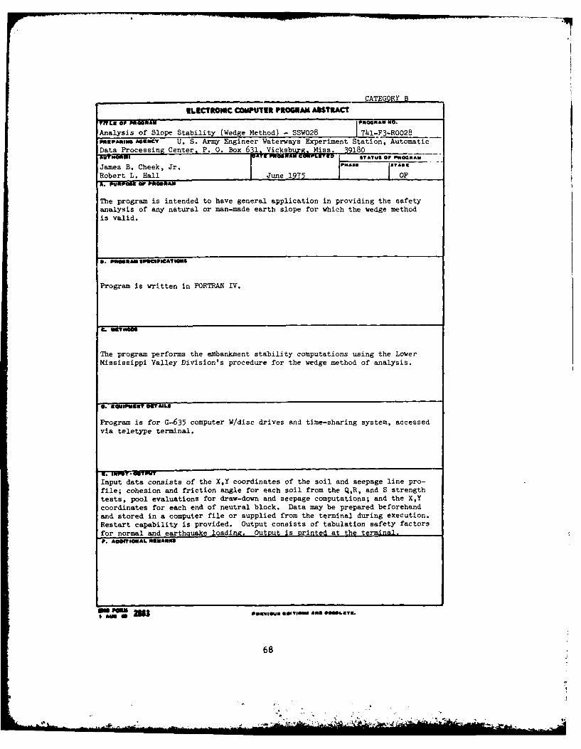
Analysis of Slope Stability (Wedge Method) - SSW028 7411" o028fSpaou. A9CTv U. S. Army Engineer Waterways Experiment Station, Automatic
Data Processing Center, P. 0. Box 631, Vicksbu~. Miss. 39180~UTOI STO5 ~ EATUS OF R0 t_
James B. Cheek, Jr. PHA9S2 1TA0IRobert L. Hall | June 1975 IOPA. ,uaur oF PUOSAM
The program is intended to have general application in providing the safetyanalysis of any natural or man-made earth slope for which the wedge methodis valid.
3. PuinmAN IP8CsPOCAtIgsS
Program is written in FORTRAN IV.
C. vUaMs
The program performs the embankment stability computations using the LowerMississippi Valley Division's procedure for the wedge method of analysis.
S. U IPm £T8.L8
Program is for G-635 computer W/disc drives and time-sharing system, accessedvia teletype terminal.
U. INPDT* .TIUTInput data consists of the X,Y coordinates of the soil and seepage line pro-
file; cohesion and friction angle for each soil from the Q,R, and S strength
tests, pool evaluations for draw-down and seepage computations; and the X,Y
coordinates for each end of neutral block. Data may be prepared beforehandand stored in a computer file or supplied from the terminal during execution.
Restart capability is provided. Output consists of tabulation safety factors
for normal and earthquake loading. Output is Printed at the terminal,. #0W AUL NUUAR09
I'~ moo 3
68
* I flA.,,

CATEGORY B
ILICTROI r COMPUTER PROGRAM ABITACT
IL or PUONAN Analysis of Slope Stability, Wedge Method P idA NO.
with Excess Pore Water Pressures (SSWO39) 74-F3-R0039PREPARING AGENCY U.S. Army Engineer Waterways Experiment Station, Automati -
Data Processing Center, P. O. Box 631,Vicksburg, Miss. 39180.AUT NONE) DATE STTNAU SOmPLET STAIUS OP PROGRAM
James B. Cheek, Jr. March 197h OFA. PRs o- - M- A
The program is intended to have general application in providing the safetyanalysis of any natural or man-made earth aope for which the wedge methodwith excess pore water pressure is valid.
U. PROGRAM SPUCiPCATHM
Program is written in FORTRAN IV.
. mo."
The program performs the embankment stability computations using the LowerMississippi Valley Division's procedure for the wedge method of analysis.
Further details on the method of solution are presented in WES K-74-2 datedMarch 1974.
0. "ouopauS DET AILS
Program is for G-635 computer W/disc drives and time-sharing system, accessed
via teletype terminal.
i. NPIDT OUTPUT
Input data consists of the X,Y coordinates of the soil profiles point; cohe-
sion and friction angle for each soil from the Q,R, and S strength tests;
pore pressure at interior points; and the X,Y coordinates of each end of neu-
tral block. Data may be prepared beforehand and stored in a computer file
or supplied from the terminal during execution. Restart capability is pro-
vided. Output consists of tabulation safety factors for normal and earth-
quake loading. Output is printed at the terminal.P. AlOENA~Lb RSEMARKS
Au at 6 ONSVIOUS Swewa Ann 0900uSSm
69

ELECTRONIC COMPUTER PROGRAM ABSTRACT
TITLE OF PROGRAM STABILITY ANALYSIS CONSIDERING UPLIFT BY THE PROGRAM NO.WEDGE METHOD (CORPS VERSION) 741-F3-A2-530PREPARING AGENCYUSAE, New Orleans District, P. 0. Box 60267, New Orleans, LA 70160AUTHOR4S) DATE PROGRAM COMPLETEDI STATUS OF PROGRAM
L. H. Manson, Jr. PHASE ISTAGEModified for CORPS by 0. J. Beer Jan 72 Mod 2 Dec 75
A. PUJRPOSE OF PROGRAM The program is intended to have general application inproviding the safety analysis of any natural or man-made earth slope embankmentfor which shear failure may occur along a surface approximated by a series ofplanes. The program is directly applicable to all cases for which the wedgemethod of stability analysis is valid.
B. PROGRAM SPECIFICATIONS The program is written in Series 600 Timesharing Fortrar
for an HIS G-635 T/S System. It follows the format required by the Conversa-tionally Oriented Real-Time Program-Generating System on the WES G-635. Theprogram is limited to a maximum of 25 profiles with 41 coordinates each. Upliftfor any strata may be calculated from one of five piezometric head profiles.Cohesion and unit weights can vary horizontally in each stratum from a maximumof 5 vertical locations. The assumed failure surface is a combination of activeand passive wedoes with central sliding block chosen to conform to (Over)c. METHODS Program used the Method of Wedges in which soil mass is divided intothree segments: an active wedge, a central block, and a passive wedge. Theassumed failure plane for the active and passive wedges are inclined 450-0/2and 450+0/2, respectively, with the vertical. Vertical boundaries are assumedbetween the central block and the active and passive wedges, and the forces oneach segment are considered separately. The factor of safety is computed withrespect to the shear strength of the soils. In general form, FS=summation ofhorizontal resisting forces divided by the summation of the horizontal drivingforces. FS=(RA+RB+RP)/(DA+DB-DP)0. EOUIPMENT DETAILS
The program is written for the WES HIS G-635 timesharing system and isexecuted from a remote teletype terminal.
E. INPUT-OUTPUTThe input data requirements were established with the convenienceof the user as a primary 'consideration; consequently, making the program easyto use, and requiring a minimum of data-preparation effort. Input data are asfollows: Two title lines, locations where unit weights and cohesion may varyhorizontally, coordinates which define the profile for each soil stratum, thefriction angle, unit weight and cohesion values for each soil stratum. Coordi-nates which define phreatic surface and piezometric head profiles if (Over)
F. ADDITIONAL REMARKS Program is not documented, but interim input write-upinformation, and program listings are available.Ref: 1. Department of the Army EM 1110-2-1902 Stability of Earth and Rock
Fill Dams. 1 April 1970.2. Department of the Navy NAVFAC DM-7 Soil Mechanics, Foundations,
and Earth Structures. March 1971NOD Eng Div ID # 5K71019; WES "CORPS" System Call Name: 10005
WES '"", 2205 A ACIt$ ONM 20 1 wCH 1 0 CfT7.
70

B. PROGRAM SPECIFICATIONS (Cont)
stratification which does not have to be horizontal. The program is designedso the user may check any stratum or any elevation within that stratum.
E. INPUT-OUTPUT (Cont)
uplift is required. Output contains the coordinates for the three segments,and the complete driving, resistance and uplift data for each.
71

CATEGORY B
ELIECTRONIC COMPUTER PROGRAM ABSTRACT
khlVL9 OF PROGRAM PROGRAI ISO.Slope Stability Analysis, Modified Swedish Method - 10009 7hl-F3-R0l0
PREPAING AGuENC U. S. Army Engineer Waterways Experiment Station, Geo -chnical
Laboratory, P. 0. Box 631, Vicksburg, MS 39160IUT OPOONAN CMPT ED STATUS Or PHOGRAI
Y. S. Jeng 19T5 Complete
1. PURPOS oP ROGRAM
This program performs embankment slope stability analysis in accordance withCorps' Manual, E4 1110-2-1902, Stability of Earth and Rock-fill Dams, 1 April1970.
S. PWOSAM SP90POCATON'
Program is written in FORTRAN.
C. INITHODS
The modified Swedish Method considering the direction of interslice forcesis used. Bilinear shear strength envelopes are constructed from the inputsof Q, R, and S strength.
a. S PmENT OT AILS
Standard equipment for the GE-600 time-sharing system is used.
U. INPUT OTPUT"Input is given in free field from a pre-generated data file with line numbersbetween 10 and 999 inclusive. The dimensional units must be in feet-kip unit.Subroutine SREAD, a special system routine developed by WES, is used to readthe continued input lines.Output may be either printed during execution or stored on a disk file whichis either pre-saved or created during execution.
P. roOSIONAL REMARKS
1. This program is included in CORPS system.
2. This program is the same as the SAVA104 stored in USERID K6APD. A similarprogram is available for batch (Program No. 741-O9-RO10).
72
* .
3. Piles, Sheet Piles &Cells
73

ELECTRONIC COMPUTER PROGRAM ABSTRACTTITLE OF PROGRAM PROGRAM NO.Three-Dimensional Pile Foundation Analysis 713-F3-A2-210PREPARING AGENCYUSAE, New Orleans District, P. 0. Box 60267, New Orleans, LA 70160AUTHORS) DATE PROGRAM COMPLETED STATUS OF PROGRAM
(Operational) PHASE STAGEH.C. Edgecombe, Jr. March 75 Mod 7 Jan 70
A. PURPOSE OF PROGRAM
The purpose of the program is to provide a three-dimensional analysis of apile foundation with battered piles.
0. PROGRAM SPECIFICATIONS
The program is written in FORTRAN IV time-sharing language for processing onthe WES G-635 time-sharing system. Source file name is A2BOO/K293D2, objectfile is executed in batch mode from a file in the CARDIN time-sharing sub-systemand from the use of the appropriate control cards in remote batch.
C. METHODS
The general method of analysis is an expansion to three dimensions (by SAUL) ofthe Hrennikoff direct stiffness methods for a two-dimensionaT analysis.
D. EQUIPMENT DETAILS
WES G-635 Computer System with disc files and time-sharing terminal and/orremote job entry terminal.
E. INPUT-OUTPUT
Technical engineering data is entered in data file "D29010". Output consistsof the forces and moments (3 dimensions) on each pile row in the foundation.Summary output is at the terminal, detailed output is on output file "P29010",and may be continued on file "Q29010" for large foundations.
F. ADDITIONAL REMARKS
Original program logic was adapted from the basic program authored by Mr. Muddin the St. Louis District Office.
Engineering ID Number 5K29009
WES UL50 2205 REP.ENG FORM 2 WHICH 1 OBSOLETE.
74

TEGORY B
ELECTRONIC COMPUTER PROGRAM ABSTRACT
TITLEOPPROGRAM Anchored Bulkhead Design by Numerical Method PROGRA6 NO.
- ANCWAL (XO027) 1713-F3-F3010PREPARIMGAGENCY U. S. Army Engineer Waterways Experiment Station, Automatic Data
Processin2 Center, P. 0. Box 631 Vicksburg, MS 39 0AUTHOR(S) DATE PROGRAM COMPLETED STATUS OF PROGRAM
Author: Mark Grazioli Written: 1965 "ASE
STAGE
Adanted for "CORPS" - WES ADPC Adapted: 1978 CompleteA. PURPOSE Of PROGRAM
Design of Anchored Bulkhead Walls by soil analysis methods.
8. PROGRAM SPECIFICATIONS
Timesharing FORTRAN )gram.
C. METHODS
The design of the walls is done by four soil analysis methods: equivalent beam;free earth support, elastic line (a fixed earth method); and equal moment.Calculates lateral loads resulting from active and passive earth pressures(including wall friction) by Coulomb theory.
V. EQUIPMENT DETAILS
Low speed terminal, central processor.
E. INPUT - OUTPUT
Input may be entered interactively from terminal or read from a previouslyprepared data file.
Output may come directly back to terminal or be stored in a file to be listedlater.
F. ADDITIONAL REMARKS
Program is available through the CORPS on WES G-635, CSC H6000 at Macon, GA, andBoeing Computer Services.
3MG FORM 2883I AUGa
75
'. ~,-, .
• ._ .: L , . I. ,..... .. .._ , ,-

CATEGORY B
ELECTRONIC COMPUTER PRtOGRAM ABSTRACT
*lYLR or PROSPIAN PROG AN 000.
BENTI - Group Pile Analysis (10002) . 713-F3-R014P0PARIIO AGINCT U. S. Army Engineer Waterways Experiment Station, Automatic DataProcessinx Center, P. O. Box 631. Vicksb-re.S 39180
AUT000051Dr. L. C. Reese and OA. ,AUS OS PNTAnDr. Frazier Parker JPA26 eVANS
Adapted for CORPS - WES ADPC Adapted 1975 COMPLETE _
T e ' UAm
Solves two-dimensional problems involving pile-supported foundations subjectedto inclined and eccentric loadings.
S. POMU SPIRCgPgAT10"
FORTRAN, Time-sharing program.
C. US M000
Consists of an iterative solution for the three equilibrium equations developedusing methods to handle the nonlinear behavior of individual piles. Thepurpose of the iterative procedure is to find the deflected position of thestructure so that equilibrium and comparability are satisfied.
0. CQUIPSINIT US AI6S
Low speed terminal, central irocessor.
I. I*PT * MTwT
Input may be entered from a prepared line-numbered data file or interactivelyat execute time. Output will be directed to an output file.
P. AONTIOUA16 UAS
Program is available through the CORPS on WES G-635, CSC 116000 at Macon, GA,and Boeing Computer Services.
am rose 2183 Vanve. uM',VON. AN. o..oLSTS.
76
.............................. .. ............... .-

ELECTRONIC COMPUTER PROGRAM ABSTRACTTITLE OF PROGRAMCANPLOT-CANTILEVER RETAINING WALL PILE ANALYSI PROGRAM NO.
Q&S CASES) Considering Uplift (Inter. Graphics Version) 741-F3-A2-020PREPARING AGENCY
USAE. New Orleans District. P. 0. Box 60267. New Orleans. LA 70160AUTHORIS) Mod. for graphics by B. 1DATE PROGRAM COMPLETED STATUS OF PROGRAM
Matherne, CANWALL ver. L. Manson PHASE STAGE
Orig., M. Lamarca & Dennis Beer June 1978 ORIGIN April 78A. PURPOSE OF PROGRAM The program computes lateral earth forces and overturningmoments for each foot of depth along a cantilever retaining wall and balanceseach to satisfy stability requirements of the method of planes thereby deter-mining the depth of penetration. It then uses the applied lateral earthforces, wave force, etc., on the pile to calculate the transverse shear force,bending moment, and deflection (from the undeformed position) at pertinent pilepositions. The program can also plot the net pressure, deflection, or bendingmoment diagrams superimposed on the strata lines by means of either anintprartivp graphir, tarminal nr a ralrnmp drjm plnttarS. PROGRAM SPECIFICATIONS
The program is written in Series HIS G-600 FORTRAN IV and uses the GraphicsCompatibility System (GCS). The program will analyze either the (S) Case orthe (Q) Case and is limited to a static water condition, impervious sheet pile,and no water seepage pattern but can consider uplift. It can analyze amaximum of 12 strata with 24 points on each stratum profile and a pile that isno longer than 150 feet.
C. METHODS
Conventional method of planes with some minor modifications is used to evaluatethe pile's stability. The shear force and bending moment at selected crosssections is determined by strength of material principals and statics. De-flections along perpendiculars from the unloaded configuration are determinedby the Moment-Area Method. Net pressure, shear force, and bending momentdiagram are plotted during the design phase.
D. EQUIPMENT DETAILS
The program requires an interactive graphics terminal similar to a Tektronix4014-1; a Honeywell Information System G-635 computer with disc capability,timesharing, and GCS; and a Calcomp 925/1036 Drum Plotter.
E. INPUT-OUTPUT Input consists of names for requested files and other teletypeprompts; job identification; head and tailwater and upper and lower tip rangeelevations; safety factor; number of strata; dynamic wave force and elevation;soil properties which includes friction angle, cohesions, and effective unitweight; coordinates to define each stratum profile; indicator to denoteexistence of tension crack; and pile properties which consists of Young'smodulus, deflection reference, moment of inertia, section modulus and pile name(0V R)
F. ADDITIONAL REMARKS
Engineering Division ID No. - 5K71053
WES ,FORo 2205 REPL.CES E.G FORM 283.WHICH IS o....
77
"- -. III

E. INPUT - OUTPUT (Cont)
Output consists of the active and passive pressures and cohesions, netpressure, water pressure, the depth of penetration and a printout and/orplot of the net pressures, transverse shear force, and bending moment atevery foot along the pile and a printout of the deflections.
78 'A
ail

ELECTRONIC COMPUTER PROGRAM ABSTRACTTITLE OF PROGRAM CANPLOT-CANTILEVER RETAINING WALL PILE ANALY- PROGRAM NO
SIS (Q&S Cases) Considering Uplift (Inter. Graphics Version) 741-X6-A2-020PREPARING AGENCYUSAE. New Orleans District" P. 0. Box 60267. New Orleans, LA 70160AUTHOR(S) Converted to BCS and modi- DATE PROGRAM COMPLETED STATUS OF PROGRAM
L vorap b Bo Mathere, PHASE STAGEWRNALt r Piansnorig. DyM. LaMarca & Dennis Beer October 1978 Mod 1 Sep 1978A. PURPOSE OF PROGRAM The program computes lateral earth forces and overturningmoments for each foot of depth along a cantilever retaining wall and balanceseach to satisfy stability requirements of the method of planes thereby deter-mining the depth of penetration. It then uses the applied lateral earth forceswave force, etc., on the pile to calculate the transverse shear force, bendingmoment, and deflection (from the undeformed position) at pertinent pile posi-tions. The program can also plot the net pressure, deflection, or bendingmoment diagrams superimposed on the strata lines by means of either an inter-active qraohics terminal or a CalcomD drum plotter.B. PROGRAM SPECIFICATIONSThe program is written in the CYBER 175 FORTRAN Extended language and usesthe Graphics Compatibility System (GCS developed at West Point). The programwill analyze either the (S) Case or the (Q) Case and is limited to a staticwater condition, impervious sheet pile, and no water seepage pattern but canconsider uplift. It can analyze a maximum of 12 strata with 24 points on eachstratum profile and a pile that is no longer than 150 feet.
C. METHODS
Conventional method of planes with some minor modifications is used to evaluatethe pile's stability. The shear force and bending moment at selected crosssections is determined by strength of material principals and statics. De-flections along perpendiculars from the unloaded configuration are determinedby the Moment-Area Method. Net pressure, shear force, and bending momentdiagram are plotted during the design phase.
D. EQUIPMENT DETAILS
The program requires an interactive graphics terminal similar to a Tektronix4014-1; a CYBER 175 computer, similar to those operated by Boeing ComputerServices, with disc capability, timesharing, and GCS; and a Calcomp 925/1036Drum Plotter.
E. INPUT-OUTPUT Input consists of names for requested files and other teletypeprompts; job identification; head and tailwater and upper and lower tip rangeelevations; safety factor, number of strata; dynamic wave force and elevation,soil coordinates to define each stratum profile; indicator to denote existenceof tension crack; and pile properties which consists of Young's modulus,deflection reference, moment of inertia, section modulus, and pile name.
(OVER)F. ADDITIONAL REMARKS
Engineering Division ID No. - 7K70005
WES ...... 2205 REPLACESt.NG FORM. *MICH. IS O .SOLE.
79
4.

E. INPUT - OUTPUT (Cont)
Output consists of the active and passive pressures and cohesion, netpressure, water pressure, the depth of penetration and a printout and/orplot of the net pressures, transverse shear force, and bending moment atevery foot along the pile and a printout of the deflections.
80
- ..

ELECTRONIC COMPUTER PROGRAM ABSTRACTTITLE OF PROGRAM .PROGRAM NO.
CANTILEVER RETAINING WALL STABILITY (Q&S Cases) "CORPS" VER. 741-F3-A2-370PREPARING AGENCYUSAE, New Orleans District, P.O. Box 60267_ New Orleans LA 70160AUTHOR(S) DATE PROGRAM COMPLETED' STATUS OF PROGRAM
PHASE STAGE
Michael G. LaMarca January 1976 Mod 3A. PURPOSE OF PROGRAM
The program determines the penetration of a cantilever retaining wall subjectedto lateral forces that impart overturning moments. It also computes lateralearth forces and overturning moments for each foot of depth and balanceseach to satisfy stability requirements of the method of planes. The programalso includes the anchored bulkhead or tieback analysis.
9. PROGRAM SPECIFICATIONS The program is written in Series 600 Timesharing FORTRANfor a HIS G-635. The program will analyze either the (S) Case, cohesion = 0,or (Q) Case, cohesion 1 0. It is limited to the following: static watercondition, sheet pile impervious, no water seepage pattern developed. Theprogram is designed to analyze a maximum of 12 strata with 24 points on eachstratum profile. The program follows the format required by the Conversation-ally Oriented Real-Time Program-Generating System (CORPS) on the WES G-635.C. METHODS
Conventional method of planes with some minor modifications is used to evaluatethe stability of the cantilever retaining wall. Stability requires that fora given factor of safety the horizontal earth and water forces are in balance(EF=O) and the overturning moments of these forces about the bottom of the wallare in balance (EM=O).
0. EOUIPMENT DETAILS
The program is written for the WES G-635 HIS timesharing system and isexecuted from a low speed remote teletype terminal.
E. INPUT-OUTPUTInput is punched on a paper tape and fed into a pre-assigned data file. Inputconsists of six basic types. Type 1 specifies whether or not tension cracksare to be computed. Type 2 consists of title and job identification. Type 3contains head and tail water, upper and lower tip range, factor of safety,total number of strata, and elevation of bottom profile at the pile. Type 4contains the dynamic wave force and elevation. Type 5 contains the soilproperties for each stratum, one line of data for each stratum. (OVER)F. ADDITIONAL REMARKS
Engineering Division ID No. - 5K71003; WES "CORPS" Library Name: 10007
WES . 2205 REPLACES ENG FORM 2093 W-CH IS 06SOLE
81
S. " ., *. A ' i " .

E. INPUT - OUTPUT (Cont)
Type 6 contains the coordinates for each profile. Output is by means of theteletype paper carriage and consists of active and passive pressures andcohesions developed, net pressure, water pressure on the protected and flood-side of the pile, and the design elevation which satisfied stability ofEF=O and EM=O.
82
.A." = ' ... ... ..- - ---;[I

ELECTRONIC COMPUTER PROGRAM ABSTRACT
TITLE OF PROGRAM CANTILEVER RETAINING WALL STABILIBY BY THE PROGRAM NO.METHOD OF PLANES (S) CASE, C=ZERO 741-GI-A2120PREPARING AGENCYUSAE, New Orleans District, P. 0. Box 60267, New Orleans, LA 70160AUTHORiS) DATE PROGRAM COMPLETED STATUS OF PROGRAM
PHASE STAGE
L. H. Manson December 1967A. PURPOSE OF PROGRAMThe program determines the penetration required to satisfy the stability requirements, the summation of unbalanced forces and moments at the required penetra-tion and the lateral water and earth pressures acting on the sheet pile.
S, PROGRAM SPECIFICATIONS
C. METHODS
Conventional techniques, with some minor modifications, were used to evaluatethe stability of the cantilever sheet pile retaining wall. The modificationswere applied in the method of evaluating the effects of lateral earth pressuresin which the ground configuration departed from the conventional horizontalcondition.
D. EQUIPMENT DETAILS
The computer hardware necessary to implement the Cantilever Retaining Wallprogram is basically the General Electric Model 225 computer, AAU version,with 8K CPU, card reader, high speed printer, and console typewriter.
E. INPUT-OUTPUT
INPUT: a. elevations of headwater on floodside and tail-ater on protected sideof the wall; b. range of sheet pile tip elevations to be investigated; c.ground elevation at the pile, & d. assigned factor of safety with respect to(S) shear strength of soil (C=0).OUTPUT: project name, stability location, factor of safety used, and date ofanalysis.
F. ADDITIONAL REMARKS
WES o.2205 REPLACES ENG FORM 2683 WHICH OBSOLETE.
83
° p -t . . . . ... . . .

CATEGORY B
ELECTRONIC COMPUTER PROGRAABSTRACT
ITLEOFPROGR M Cantilever Retaining Wall Design and Analysio nR
CANWCAL (X0026) 741-F3-A2999
PEPaRyze AENCY U. S. Army Engineer Waterways Experiment Station, Automatic DataProcessing Centerm P. 0s Box 631b Vi Wge, an iRt
AUTHOa($) OATE PROGRAM COMPLETED PHsSTATUS OF PROGRAM
Author: Leonard H. anson Written: 1977 PHSSTAGE
Adated for "ORPS" - WES ADPC essodr 1978 Complete IE. PURPOSE OF PROGRAM
Determines the penetration of a Cantilever Retaining Wall subjected to lateralforces.
B. PROGRAM SPECIFICATIONS
Timesharing FORTRAN Program.
C. METHODS
Determines the penetration of the Cantilever Retaining Wall by method of planes.Analyzes the wall as a cantilever beam fixed at the theoretical depth of pene-tration, and determines shears, bending moments, and deflections per foot of
wall.
D. EQUIPMENT DETAILS
Low speed terminal, central processor.
E. INPUT -OUTPUT
Input may be entered only from a predefined data file named D71004.
Output is stored in three predefined files to be listed later. The names ofthe files must be P71004, Q71004, R71004.
F. ADDITIONAL REMARKS
Program is available through the CORPS on WES G-635, CSC H6000 at Macon, GA,and Boeing Computer Services.
ENG FORM 2183
1 AUG 0
84

CATEGORY 8
ELECTRONIC COMPUTER PROGRAM ABSTRACT
TITLE OF PROGRAM Analysis of Circular Cofferdam or Mooring PROGRAM NO.Cell Founded on Rock - CELLRK (X0028) 1713-F3-H3190
PREPARING AGENCY U. S. Army Engineer Waterways Experiment Station, Automatic DataProcessing Center, P. 0. Box 631, VicksburR. MS 39180
AUThOR(S) Author: walter (reen |DATE PROGRAM COMPLETED STATUS OF PROGRAMRandall Warren I Written: 1974 PHASE STAG E
Adapted for "CORPS" - WES ADPC Adapted: 1978 Complete
A. PURPOSE OF PROGRAM
Analysis of a circular cofferdam cell or circular mooring cell of a givenequivalent width under specified loading conditions.
5. PROGRAM SPECIFICATIONS
Timesharing FORTRAN Program.
C. METHODS
Computes the following safety factors for circular sheet pile: Sliding;slipping between pile and cell fill; vertical and horizontal shears; and inter-lock tension. Follows method of analysis outlined in "USS Steel Piling DesignMethod."
0. EQUIPMENT DETAILS
Low speed terminal, central processor.
E. INPUT- OUTPUT
Input may be entered interactively from terminal or read from a previouslyprepared data file.
Output may come directly back to terminal or be stored in a file to be listedlater.
F. ADDITIONAL REMARKS
Program is available through the CORPS on WES G-635, CSC H6000 at Macon, GA,and Boeing Computer Services.
ENO FORN 2813t AUG 60
85

CATEGORY B
ELECTROIC COMPUTER PROGRAM ABSTRACT
TITLE OF PRPGRAM OPGOGRA NO.
Cellular Sheet Pile Structure - ELLSL (X029) 71u-Fn-FgseoPREPARINGAGENCY U. S. Army Engineer Waterways Experiment Station, Automatic Data
Processing CenterA P. 0. Box 631 Vicsburg, MS 39180AUTNOi S) DATE PROGRAM COMPLETED • STATUS OF PROGRAM
Author: Elex Alter IWritten - 1 966 IPH ASE .. ITGAdapted for "CORPS" - WES ADPC Adapted - 1978 1 Compl1ete
A. PURPOSE OF PROGRAM
Design of a sheet pile or a parallel wall by the Cumming's Method.
5. PROGRAM SPECIFICATIONS
Timesharing FORTRAN Program.
C. METHODS
The program uses an input equivalent width of cell or computes an initialequivalent width. All overturning moments computed are added accumulatively.The equivalent width of the cell with a tilting factor of safety greater than1.5 is determined, or it determines a factor with a given equivalent width.
0. EQUIPMENT DETAILS
Low speed terminal, central processor.
. INPUT - OUTPUT
Input may be entered interactively from terminal or read from a previouslyprepared data file.
Output may come directly back to terminal or be stored in a file to be listedlater.
P. ADDITIONAL REMARKS
Program is available through the CORPS on WES G-635, CSC H6000 at Macon, GA,and Boeing Computer Services.
ING F~OM 2883
86
- S ,Sq~ , j ~ -

CATEGORY B
ILIECTRONIC COMPUTER PROGRAM ASTIRACT
TITLe o PRWOGRAN .GA g
CO62 - Laterally Loaded Pile Analysis (10001) 3 018PUSPAfING AS6 T U. S. Army Engineer Waterways Experiment Station, Automatic DataProcessing Center. P. 0. Box 631. V b1
AUSI a %W6A [TO STATUS Or P"OG MANDr. L. C. Reese ,. S.auo - -"Dr. N. RadhakrishnanAdapted for CORPS - WES ADPC Aiapted 1975 COMPLETE 1*'A. PURIPOSIK i IO~
Analyzes laterally loaded piles in nonlinear soil media. Solves for deflectionshear, moment, and reactions in a single pile under a variety of boundaryconditions specified at the top of the pile.
a. PIRGAINa Speorl"CT WIl
FORTRAN, Time-sharing program.
C. 19v No"
In the analysis used in COM62, compatibility is achieved between the inelasticsoil and the elastic pile (which is elastically restrained by the superstructure) by repeated application of the elastic theory. The iterativeanalysis consists of a conventional beam on elastic foundation analysis coupledwith the proper prediction of force-deformation characteristics of the soil.
0. *OUMBINE AILS
Low speed terminal, central processor.
f. INPUT - OUTPUT
Input may be entered from a prepared line-numbered data file or interactivelyat execute time. Output will be directed to an output file.
P. A@OfNAL 141aPau
Program is available through the CORPS on WES G-635. CSC H6000 at Macon, GA,and Boeing Computer Services.
p 2883 PAgivuG ESHI*O W..U, O.LC3.
87

CATEGORY B
ELECTRONIC COMPUTER PROGRAM ABSTRACTTwL9 Or PROGRAM PRtOGRAM NO.
Anialyses of Pile-Soil Interaction (DUKFOR) 741-F3-R0008,.SPARnMO AOENcv U. S. Army Engineer Waterways Experiment Station, GeotechnicalLaboratory, P. 0. Box 631, Vicsu I ls5 "
ATE UTQUNAU CaULETRO STATUS OF PROGRAM
B. PSOMNAM SPWCIFICATIGOS
Written in standard FORTRAN.
C. EST MOS
One-dimensional finite difference analysis. Incorporates compatible dynamicequilibrium and static incremental equilibrium solutions to simulate impactpile driving and/or pile load test behavior.
0. RSImPMAu OS AILS
G-635 computer.
R. INPUT-OUTPUT
See program documentation described below.
A" USARUScunttion contained in WES Contract Report S-7S-5, "The Mechanics of Pile-
Soil Interaction in Cohesionless Soils," by D. M. Holloway, Dec 1975, and WVESContract Report S-76-14, "User's Manual for DUKFOR, A Computer Program forAnalyses of Pile-Soil Interaction," by D. M. Holloway, Sept 1976.
a" 28FORMgu 6$Y#
0 AMC88

ELECTRONIC COMPUTER PROGRAM ABSTRACTTITLE OF PROGRAM PROGRAM NO.
NRFNNTKnFF PH F ANAI YSIS WITH SUMMATION OF RESU1 TS 713-F3-A2-150PREPARING AGENCYUSAE. New Orleans District. P. 0. Box 60267, New Orleans LA 70160AUTHORIS) R. Villarubia, G. M. Finley DATE PROGRAM COMPLETEDI STATUS OF PROGRAM
C. W. Ruckstuhl, Jr., and D. J. PHASE STAGEElguezabal I May 74 Mod 8 1968A. PURPOSE OF PROGRAM
Compute actual axial and transverse loads, and allowable transverse loads,on each pile row for each set of applied forces and moments on a given pilearrangement of a battered pile foundation by the Hrennikoff Method.
8. PROGRAM SPECIFICATIONS
Program is written in ASA FORTRAN with free-field input format.
C. METHODS The methoo useo or computation o actual pile ioaas is explainep in"Analysis of Pile Foundations with Batter Piles", by A. Hrennikoff, ASCE Trans-actions, Vol. 115, 1950, pp. 351-382. The basis for the computation of theallowable transverse loads is the theory that the sum of the ratios of actualaxial stress to allowable axial stress and maximum actual flexural stress toallowable flexural stress must not exceed unity. For hinged end piles, thecoefficient for maximum moment is assumed to be 0.50 which is alightly greaterthan the coefficient indicated in "Generalized Solution for Laterally LoadedPiles", by H. Matlock and L. C. Reese, ASCE Journal of Soil Mechanics (Over)0. EQUIPMENT DETAILS
Program is written for use on a G-635 computer with GCOS operating system andFORTRAN time-sharing sub-system. Two disc files may be used for input andthree scratch disc files are used. Program is accessed on the WES time-sharingsystem via remote terminal.
E. INPUT-OUTPUT Input consists of control variables, soil and pile properties,
pile arrangement information and applied forces and moments for each load con-dition. Input can be via terminal keyboard as the program requests input inconversational mode; from input data file D29004 saved prior to running thisprogram; from a binary output data file created and saved by program number713-F5-A2-110 plus terminal keyboard input or from a binary output from713-F5-A2-110 plus input saved on data file 029004. User has the option (OVER
F. ADDITIONAL REMARKS
Program Is limited to two dimensional applied loading and assumes all pilesin the same row carry equal loads. The computation of allowable transverseloads is limited to hinged end piles.
Program is operational and has been tested within above limitations. Programis not documented, but listing and input information are available.
WES ° 2205 R(EPLACE tEN 0rA 2o06 WHICH 1, OBSOLETE.
89
bem

C. METHODS (Cont)
Vol. 86, No. SM5, Proc. Paper 2626, Oct. 1960, PP 63-91. Program has also beenmodified to accept values for a stratified soil. The program has not yet beenexpanded to compute allowable transverse loads for piles that are consideredto have their heads fixed in the pile cap.
E. INPUT-OUTPUT (Cont)
of obtaining a printout of all computed pile loads for each load condition; aprintout of only the results for each pile row for the respective criticalload condition, or a printout of the maximum allowable pile spacing for eachpile row based on the respective critical load conditions.
90
- - m e s a

CATEGORY B
ELECTRONIC COMPUTER PROGRAM ABSTRACT
TITLE OF PROGRAM PROGRAM NO.LNIVDPILE - Rigid Cap 2- and 3-D Pile Analysis 713-F3-R0026PREPARING AGENCY U. S. Army Engineer Waterways Experiment Station, Automatic Data
Processinp Center, P. 0. Box 631. Vicksbur2. MS 39180AUTHOR(S) DATE PROGRAM COMPLETED STATUS OF PROGRAM
PHASE STAGEDeborah Kaufman December 1976 INIT OP
A. PURPOSE OF PROGRAM
This program is a general method of analysis by direct stiffness of two- andthree-dimensional pile foundations. The pile foundation consists of a groupof piling placed into the soil topped with a rigid cap. Loads to the cap aretransmitted by the piling to the soil. Determinations of deflections andindividual pile loads are computed as required by the designer. Adequaterepresentation of the soil-pile interaction is necessary.
5. PROGRAM SPECIFICATIONS
G-63S FORTRAN
24K Core
C. METHODS
The base is assumed rigid. Piles in a three-dimensional analysis are repre-sented by a 6x6 stiffness matrix as proposed by Hrennikoff. In a two-dimensionalanalysis the piles are represented by a 3x3 stiffness matrix. The subgrademodulus may be constant or linearly varying. The solution.is by a directstiffness method.
D. EQUIPMENT DETAILS
Interactive T/S Terminal
Honeywell G-635
E. INPUT -OUTPUT
Input generally consists of pile geometric, material and fixity properties andthe applied loads. Data may be input interactively or saved in a file prior tothe run. (Detailed guide available from WES ADP Center).
Outputs structure, and pile deflections, pile forces along pile axis and alongstructure axis. Output may be directed to the terminal or saved in a file.Pile forces along the structure axis may be saved in a file.
F. ADDITIONAL REMARKS
ENG FAMU0 2883
91
4I

CATEGORY B
IELECTRONIC COMPUTR PROGRAM ABSTRACT
rNTLE OF PROGRAM PROGAAM NO.
MAKE - Generate P-Y Curves (10004) 0713-3-R0016PREPARmNG SMIC U. S. Army Engineer Waterways Experiment Station, Automatic Data
Processing Center, P. 0. Box 631, Vicksbur, MS 39180
~~~UT~~K IOE AEP A OPEE STATUS OP PROGRIAMDr. Frazier Parker IPHASE
Adapted for CORPS - WES ADPC Adapted 1975 COMPLETEA. PURIIPOGE OP PgRRAN
Generates soil resistance (p) versus pile movement (y) curves for soilssurrounding a laterally loaded pile based on certain laboratory soil test
results.
1. PPR SERA SPSCIPICATIOM
FORTRAN, Time-sharing program.
C. luff HOoG
Uses different criteria for clays and sands. MAKE can handle any number ofstratums of clay or sand and can also account for various pile diameters.
S. IIPUEUIST AILS
Low speed terminal, central processor.
a.' 111iFT-*OUTF IT
Input may be entered from a prcpared line-numbered data file or interactively
at execute time. Output may be directed to an output file or come directlyback to the terminal.
V. AO tIooAL RtmARKS
Program is available through the CORPS on WES G-635, SC H6000 at Macon, GA,ant Boeing Computer Services.
a" a, 2333 PREVIoI, EOVV,@,, ARE 2883O. rI AUG "4
92

Ar D-A103 3A4 ARS ENGINEER WATERWAYS EXPERIMENT STATION VICKSBURG MS F/G 13/13LIST OF SOILS, SOIL-STRUCTURE INTERACTION AND OTHER RELATED COM-ETC(U)
MAY Al N RADHAKRISINAN, P K SENTER
UNCLASSIFIED WES-TA K-8- AlEE2 EEEEE2EEilhEmhEmhhEEEmhEmhhohmhhhEE
END omomoo

CATEGORY B
ULECTSOIC COWUTERt PROGRAM AISTUACT
Le F 00W A 30PILE- Indeterminate Pile Analysis by RGA
Matrix Method (X0014) .. 3-A3840
.S. Army Engineer District. St, LoursLUTIOD M51 5-7NNgaiI~rI[ SU OW PfqOiImh
Thomas Mudd C.*i.ETED
Joseph Hartman August 1975.,RIpFO V PMEM
This program is a general method ot analysis by direct stiffness of three-dimensional pile foundations. The pile foundation consists of a group ofpiling placed into the soil topped with a rigid cap. Loads to the cap aretransmitted by the piling to the soil. Determinations of deflections andindividual pile loads are computed as required by the designer. Adequaterepresentation of the soil-pile interaction is necessary.
j7. psMMsU #pgCIpWATW"
Batch FORTRAN and Timesharing.
C. =1TUS
The base is assumed rigid. Piles are represented by a 6X6 stiffness matrixas proposed by Hrennikoff. The solution is by a direct stiffness method.
o. , Klrr "T45"
Five temporary disk files, each 1OL in size.Low speed terminal, central processor.
M. *UFT-OTU-T
Input can be on cards, in a timesharing file, or input interactively.
Output can be written to a timesharing file or printed on the terminal.
P. £UNWIlaAL .lnuama
Hrennikoff, A., "Analysis of Pile Foundations with Batter Piles," Transactions,ASCE, Vol. 115, 1950, pp. 351-382.
Saul, William E., "Static and Dynamic Analysis of Pile Foundations," Journalof the Structural Division, ASCE, Vol. 94, No. STS, Proceedings Paper 5936,May 1968, pp. 1077-1100.
Program is available through CORPS on WES G-635, CSC H6000 in Macon, GA, andocng C~omputer Service.
2833 .. sw0 og amyloows ram. Omin.at.
OLL 93 r

ELECTRONIC COMPUTER PROGRAM ABSTRACTTITLE OF PROGRAM PROGRAM NO.
PILE CAPACITY COMPUTATIONS 741-F3-A2-l 10PREPARING AGENCYUSAE, New Orleans District, P. 0. Box 60267, New Orleans, LA 70160AUTHOR(S) DATE PROGRAM COMPLETED STATUS OF PROGRAM
PHASE STAGEDennis J. Beer December 1974 ORIGIN
A. PURPOSE OF PROGRAM
The program computes the pile bearing capacity which results from the pile endbearing, if applicable, and from the pile skin resistance from cohesion oradhesion and from friction. The pile capacity is computed for a pile in eithercompression or tension when the pile tip is either at the top, middle, orbottom of each stratum or at the top or bottom of each stratum and any otherelevations selected by the user.
B. PROGRAM SPECIFICATIONS
The program is written in Series 600 Timesharing FORTRAN. The program islimited to fifteen strata and to either timber pile, square or octagonalconcrete pile, or steel "H" pile. The bearing capacity is determined for upto thirty different locations of the pile tip.
C. METHODS
The program stores all input properties in arrays and using a bookkeepingprocess, it determines the output parameters as if the pile is being drivento pertinent elevations.
D. EQUIPMENT DETAILS
The program is written for the WES G-635 HIS Timesharing system and isexecuted from a low speed remote terminal.
E. INPUT-OUTPUT
Input data consists of the following for each soil stratum: the frictionangle for soil to soil or soil to pile, the weight density, the coefficientsof lateral earth pressure and Terzaghi's bearing capacity factors, theelevation of each stratum break at the pile and the cohesion at the top andbottom of each stratum. Also pile type and dimensions are given.
(OVER)
F. ADDITIONAL REMARKS
Engineering Division ID No. - 5K71039
WES I JUo 2205 REPLACES EN FORM .-. C. a .. SOLEE.
94

E. INPUT - OUTPUT (Cont)
Output is a listing of the input data and of the skin cohesion or adhesionresistance and frictional resistance, the end bearing, if applicable, andthe total pile capacity with end bearing and without end bearing for thepile Vose tip is either at the top or bottom of each stratum, or either themiddle of each stratum or other elevations selected by the user.
95

ELECTRONIC COMPUTER PROGRAM ABSTRACT
TITLE OF PROGRAM PROGRAM NO.PILE CAPACITY COMPUTATIONS 741-X6-A2-110PREPARING AGENCYUSAE, New Orleans District, P. 0. Box 60267, New Orleans, LA 70160AUTHOR(S) Dennis J. Beer; converted DATE PROGRAM COMPLETED STATUS OF PROGRAM
to Boeing Computer Services by PHASE STAGEK. Broussard September 1978 Mod 1 Aug 78
A. PURPOSE OF PROGRAMThe program computes the pile bearing capacity which results from the pileend bearing, if applicable, and from the pile skin resistance from cohesionor adhesion and from friction. The pile capacity is computed for a pilein either compression or tension when the pile tip is either at the top,middle or bottom of each stratum or at the top or bottom of each stratumand any other elevations selected by the user.
B. PROGRAM SPECIFICATIONS
The program is written in the CYBER 175 FORTRAN Extended language. The programis limited to fifteen strata and to either timber pile, square or octagonalconcrete pile, or steel "H" pile. The bearing capacity is determined for upto thirty different locations of the pile tip.
C. METHODS
The program stores all input properties in arrays and using a bookkeepingprocess, it determines the output parameters as if the pile is being drivento pertinent elevations.
D. EQUIPMENT DETAILS
The program requires a computer system similar to the Boeing Computer Services'CYBER 175 timesharing system and is executed from a low speed remote dataterminal.
E. INPUT-OUTPUT Input data consists of the following for each soil stratum: the
friction angle for soil to soil or soil to pile, the weight density, the coeffi-cients of lateral earth pressure and Terzaghi's bearing capacity factors, theelevation of each stratum break at the pile and the cohesion at the top andbottom of each stratum. Also pile type and dimensions are given.Output is a listing of the input data and of the skin cohesion or adhesionresistance and frictional resistance, the end bearing, if applicable, (OVER)
F. ADDITIONAL REMARKS
Engineering Division ID No. - 7K70007
WES ,Om", 2205 REPLACES G FORM 296. WHICH 1 OSOLETE
96

E. INPUT - OUTPUT (Cont)
and the total pile capacity with end bearing and without end bearing for thepile whose tip is either at the top or bottom of each stratum, or eitherthe middle of each stratum or other elevations selected by the user.
97
- 7~~'*~'

CATEGORY B
ELECTRONIC COMPUTER PROOBAM ABSTRtACTfJYLE OF PUGAZ .ee* p.
PX4C3 - Axially Loaded Pile Analysis (10003) 7-F3-RO0I5POARNAsusuCV U. S. Army Engineer Waterways Experiment Station, Automatic DataProcessing Center, P. 0. Box 631, VicksburgM 39180
RuT9OU' Dr. L. C. Reese, Dr. '. "_ DQATE INUPE STATUS 0V PU"UM-
Coyle and Dr. N. Radhakrishnan -PAG 1
Adapted for COPPS - WES ADPC Adapted 1975 COMPLETEW-ft*1a9 Wv FROAIN
Analyzes axially loaded piles in nonlinear soil media. Computes load-displace-ment relationships for axially loaded piles, where the pile has a constantoutside diameter.
9. pMoGNAN rnSPQCWAWm
FORTRAN, Time-sharing program.
C. *STO
Uses finite difference equations to achieve compatibility between pile dis-placement and load transfer along the pile and between soil resistance anddisplacement at the tip of the pile.
AL £equoU1 6VFA&
Low speed terminal, central processor.
Input may come from a prepared line-numbered data file or interactively atexecute time. Output may be directed to an output file or come directly backto the terminal.
Program is available through the CORPS on WES G-635, CSC H6000 at Macon, GA,and Boeing Computer Services.
?F"N 283...w ovoeAIo.iv.
98

CATEGORY B
ELECTRONIC COMPUTER PROGRAM ARSTRACTtwroPP''s au Design/Analysis of Sheet Pile Walls by RN "a.
Classical Method - SHTWAL (XO031) 1713-F3-RO039mPPAOINm3.Cv U. S. Army Engineer Waterways Experiment Station, Automatic DataProcessing Center, P. 0. Box 631, Vicksburg, .S 39180
AUTWO"10| IATO 'Hung M CPLTD ISATUS OF POORAma
Author: William P. Dawkins Written - 1979 P" BYaAdapted for CORPS - WES ADPC COMPLETE~~~~Adap~ted - 1979 C LLT
'X. OURFP O POmmWMF
Performs either a design or analysis of an anchored or cantilever sheet pileretaining wall.
U. pummIAm SPUlCIPSCAtl4
FORTRAN, Time-sharing program.
C. ?T HOe S
Uses classical soil mechanics procedures for determining the required depthof penetration of a new wall or assesses the factor of safety of an existingwall.
. EdfFUn? EMALS
Low speed terminal, central processor.
s. ,U'Hr. PUT
Input may be entered from a predefined data file or interactively at executetime.
Output will be directed to an output file and/or directly back to the terminal.
F. ADWM$" ""urnam
Program is available through the CORPS on WES G-635, CSC H6000 at Macon, GA,and Boeing Computer Services.
e uoe 233 .. uwlusuw',.w' a.. e..in ..
99
C,ilk
LOW"

CATEGORY B
ELECTROMS C WUTE3 PROGRAM AISTIACT
"TLE OF pokcam" SSIWALL - Analysis of Sheet Pile Wall by A6NNoSoil-Structure Interaction Method (X0033) 713-F3-ROO51.suew aftcv U. S. Army Engineer Waterways Experiment Station, AutomaticData Processing Center, P. 0. Box 631. Vicksburg. MS 39180
AUT MOUWU 1D ATE PNDNAN CgllO[TUD STATUS OF PUOGRAM
Dr. William P. Dawkins WAo.. i,, o -
Adapted for "CORPS" - WES ADPC Written - 1979 Complete, pumpm ao PoGRAM
This is a special purpose program which performs soil-structure interaction(SSI) analysis of either anchored or cantilever retaining walls. Simplifiedprocedures are incorporated in the program to automatically gererate the soilforce-displacement characteristics from conventional soil properties.
U9. PrUOSAM spmCPICATNU
FORTRAN IV, Timesharing program.
C. *9E NO"
A one-dimensional finite element model of the sheet pile wall is establishedby defining nodes at three inch intervals starting at the top of the wall;at soil layer boundaries; at water surface elevations; at anchor attachmentpoints; at points of application cf horizontal live loads; at points describ-ing an applied horizontal pressure distribution; and at the bottom of thewall.
D. US HI ? OT AILS
Low speed terminal, central processor
N SPUT.OUTPUT
Input may be entered from a predefined data file or interactively at executetime.
Output may be directed to an output file or come directly back to theterminal.
F. AOMT"IMALAISANKS
Program is available through the CORPS on WES G-635, CSC H6000 at Macon, GA,and Boeing Computer Services.
I AU~G to
100
* -~ a

CATEGORY B
ELECTRONIC COMPUTER PROGRAM ABSTRACT
TIELS OP l AM 5".OG.At.0.
Wave Equation Analyses of Pile Driving (TAMPOR) 741-F3-R0007
pmePNswo AsGECv U. S. Army Engineer Waterways Experiment Station, Geotechnical
Laboratory, P. 0. Box 631. Vicksburg. M. 39180
D. Michael Holloway June 1975 Init IVASP
A. PURPOSE OF PROGRAM
One-dimensional wave equation analysis for analyzing impact pile-driving
behavior.
-. PSOMNAM SPECIPICATIONS
Written in standard time-sharing FORTRAN.
C. IUTnOS
Program adapted from Texas A&M University programs and converted to a time-
sharing mode.
S. EQUPURNT DETAILS
G-635 computer with time-sharing capability.
SP OUTPUT
See documentation described below.
F. AOOITIOAL REMANKI
Documentation contained in WES TR S-75-5, "Wave Equation Analyses of Pile
Driving," by D. H. Holloway, June 1975.
POh2333 Pmu,,gg *,y,og.* Lag OSAGIETE.I AUQ 2S
101
rp
*

CATEGORY B
ELECTRONIC COMPUTIER PROGRAM ASTRACT
WESTrI -- Wave Equation Analysis of Pile Foundations 009
P"UAINsecy U. S. Army Engineer Waterways Experiment Station, GeotechnicalLaboratory, P. 0. Box 631, Vick.b MS3
AUTWMorm OATWI lU~aZ"Ili OIL9TjD STATUS o OGNlll&Mi
T. J. Hirsch; L. Carr; and L.L. '"AS STABSLoweryWES Contact: Hu h M. Taylor Jr Avril 1976 INIT. PUReOS or PH AnU
The program performs wave equation analysis of piles driven by a single blowof the hammer. Conventional pile and soil models were used. The program canbe used to predict impact stresses in piles during driving and to estimatethe static soil resistance on piles at the time of driving.
D. PROM SIPSIeFICATMI
C. RET""OS
E. A. L. Smith's original numerical procedure was used in the wave equationcomputations.
0. 19WIPUCHT OCTAIL
f. INFVT-OUTPUT
Input forms and guidance are available in Volume 11 of manuals. Output isprinted out in three basic sections. A summary of input data, time dependentsolution for forces, and displacements of selected pile elements, and asummary of maximum compressive and tensile forces, maximum observed dis-placements and the permanent set per blow of the hammer and miscellaneousinformation are contained in the manuals.
P. ADOEIGU A, UUA"MUManuals by the Federal Highway Administration that describe the program and
its use are: Vol. 1, Background, Report No. FHWA-IP-76.13.1; Vol. II, ComputerProgram and Sample Problems, Report No. FIIWA-IP-76-13.2; Vol. III, ProgramDocumentation, Report No. FHWA-IP-76-13.3; and Vol. IV, Narrative Presentation,Report No. FHWA-IP-76-13.4.
Doran* 2853 p,¥vsie SmfSNO An *aaemLa~
102

CATEGORY B
LIECTROtlIC COiPUTER PROGRAM ABSTRACT
TiTLE OF P0106MAN "mea' g
WESWEAP -- Wave Equation Analysis for Piles 741-13-R0010
PUEPAINWGAGEMCV U. S. Army Engineer Waterways Experiment Station, GeotechnicalLaboratory, P. 0. Box 631, Vicksburg MS 39180AuTWOwItt1 'T PROGRAM VOPLET O STATUS OP PROGRAM
G. G. Goble and Frank Rausche ...uy 176 '*
S
WES Contact: Hu h M. Taylor,. July 1976 INIT OPA. PURPOKE O
f PROWRAM
The program performs wave equation analysis of piles driven by a single blowof any type of impact hammer. Conventional pile and soil models were used inaddition to both a thermodynamic model for diesels and refined mechanicalhammer models. The program can be used to predict impact stresses in pilesduring driving and to estimate static soil resistance on piles at the time of
driving.
M. ProAMn SPUCIFICACOS
The program development was aimed at providing a simple input and both aflexible and extensive output that include automatic plotting capabilities.
The computer language is FORTRAN IV.
C. MET moos
The pile and driving systems are represented by a series of discrete masses
and springs. The soil is modeled by a spring and a dashpot attached to each
mass. The soil resistance so represented are linear elastic plastic. The
elastic resistances are linearly proportional to the element velocity for thevelocity. By using Newton's Second Law, accelerations and displacements are
calculated and the computation proceeds to the next time increment.
0. UQUIPORKMt? T AoLA
. IMPUT* OUTPUT
A short input and long or complete input forms are available. Common hammerproperty data are stored in a file. Input data is reprinted, options ofprinted and plotted parameters are available, and time plots are optional.
P. A004TIONAL RUMAIA
Manuals by the Federal Highway Administration that describe this program andits use are: Vol. 1, Background, Report No. FHWA-IP-76-14.1; Vol. II, UsersManual, Report No. FHWA-IP-76-14.2, Vol. I1, Program Documentation, ReportNo. FHWA-IP-76-14.3; and Vol. IV, Narrative Presentation, Report No. FHWA-IP-76-14.4.
103
St"

4.Seepage
104

CATEGORY B
ELECTROMtC COMPUTER PROGRAM ABSTRACT
TITLs OF PROmRAM -- •ROGN"Mo.Two-dimensional finite element method seepage program. I 704-F3-R0245
PBSPgA0-G Aaucv U. S. Army Engineer Waterways Experiment Station, Automatic DataProcessing Center, Vicksburg, Miss. 39180
liat NOUSIATI PROGRAMrCONPL[T90 STATUS OF PROGRAM
Fred T. Tracy May 1973 Exp OP
A. PUIRPU OF PWSRAM
This program solves plane and axisyuetric steady-state and transientseepage problems by the finite element method (FEM).
S. PuoGmAM SPUCIFCIATONS
FORTRAN, single precision.
C. ow moosRefer to Tracy, F. T., "A Plane and Axisymmetric Finite Element Program forSteady State and Transient Seepage Problems," Miscellaneous Paper K-73-4,May 1973, USAE Waterways Experiment Station, CE, Vicksburg, Miss.
0. IQUIPUINT WSTAILS
G-635; memory requirements vary according to program size; file codes1, 2, 3, 4, and 7 are used for temporary storage.
I. INPUT-OUTPVT
Input consists of the FEN grid information on cards. Output consists ofthe following printed information:
a. A printout of the input data.
b. Heads and flows at the nodes.
P. A0 ,weAL UMUURA8c. Discharge velocities at the centroids of the elements.
d. The position of the phreatic surface for unconfined flow problems.
ma patp~ fTOOAle0MR5
105
* j.~-i

CATEGORY H
IUIRCTRONIC COMPUTER PROGRAM AUSTRACT
TlLE OP PRUORANTjree-D.ensional Finite Element Program for P NRA NO.
Steady-State and Transient Seepage Problems. 704"F3-I218paaN AGENCY U. . Army nglneer Waterways Experiment Station, Automatic Data
Processing Center, P. 0. Box 631, Vicksburg, Mississippi 39180AUTMOESI FTar7 PHUNA SLSE STATUS OF PROGRAM
IP E IST6Fred T. Tracy May 1.973 Exp IOP
. PURPOSE U PROUnAM
This program solves three-dimensional steady-state and transient seepageproblems by the finite element method (FEM).
S. PRMoSAN SPUCIFOCA wIOS
FORTRAN, single precision.
C. UNH oosRefer to Tracy, F. T., "A Three-Dimensional Finite Element Program forSteady-State and Transient Seepage Problems", Miscellaneous Paper K-73-3,May 1973, USAE Waterways Experiment Station, CE, Vicksburg, Miss.
0. URQUfPOU DeAILSG-635; mswmry requirements vary according to problem size; file codes1, 2, 3, 4, and 7 are used for temporary storage.
U. INPUT-OUTPUTr
Input consists of the FEK grid information on cards. Output consists of thefollowing printed information:
a. A printout of the input data.
b. Heads and flows at the nodes.
F. AmT MIMAL RSMARKIc. Discharge velocities at the centroids of the elements.
d. The position of the phreatic surface for unconfined flow problems.
I AUG a f 0
106
"- "i-..-~l d .. -1 '

CATEGORY B
RgCACCOPTER PROGAMu3 ASMACT PP..A
ToDesign reifwl spc g for annfinite system of weie ells as15 suggested
by S Technialeeranu iti oS. 3-au l. .
I. STTU P RGNt
of t.hnel and the uni fllgowsan eemndb extralbdarodiin
roesin rl well ofiuaing ftra and errorit syutimo). lsa sgese
Lo WSe Termnial, etralu pocessor.Vo.1
prmeardg daT A file. am
OTput mayig prcedirecl ckt of terkinal borh be store inrasfile t belnliste wlter. euitfosa etrie yexenlbudaycniin
Proga is caible wthog the CORPS oniale aEs detemine byC euatiaonsA
Bow ein temial CYB tra 17oeso.
-. 1WV-41T
Inpu ma2 eetrditeatvl3rmtemnlo5edfrmapeiul
prepard dat 107e

5. Stress Computation, Settlement, & Consolidation
108

CATEGORY B
ELECTRONIC COMPUTER PROGRAM ASiTRACT
TffL. OF PROGAM PAONAM NO.
Analysis of One Dimensional Consolidation - FD31 (10011) 1741-F3-R0106PREPARING AEucy U. S. Army Engineer Waterways Experiment Station, AutomaticData Processing Center, P. 0. Box 631, Vicksburg, MS 39180
AUTHONW RAT[ WmNAU COUPL[TEO I STATUS OP PRORAM
Dr. Roy Olson, Univ. of Texas PHAS SAe
Modified by: Reed Mosher, WES 1980A. PIJ0POS OFIP PROoAm
FD31 is a computer program which computes the settlements and rates of settle-ment in a multi-layered conesive soil profile.
a. PROGNAM PUPCIFCAtHMIG
C. MET NOOG
The settlements and rates of settlement are computed by the use of finitedifference methods applied by Terzaghi's one-dimensional consolidationtheory.
0. EOutPUMeT OSrTAIr
Standard equipment: Honeywell 600, 6600-Series
ff. INPUT *UTpT
Input is read into program in free field from a data file interactivelyfrom the terminal.
Output is printed to the terminal and/or the outfile.
P. AGSOWONAL RKUARMS
This program is included in the CORPS system. Complete documentation isavailable from the Engineering Computer Programs Library (ECPL), WES.
I09 2M P08VIOU9 807Y0000 ANN SULEE.
109

CATEGORY B
ELICTRO4IC COMPUTUR PROGRAM ABSTRACTIffLt Of PROmAN Magnitude of Settlement of a Multi-Layered PRORAM NO.
Soil System (MAGS r) (10010) 74 i-F3-R015PREPA1NS 0 ANC U. S. Army Engineer Waterways Experiment Station, AutomaticData Processing Center, P. 0. Box 631. VicksurR, MS 39180
aU ! R. L. Schiffman, V. Partyha, oITE PUUAW COUPL[TEO STATUS OP PROGRAMand D. Jubenville, Univ. of Colo pw0 jPA8 1TO,Modified by: Reed Mosner, WES 1980
A. R.M b PivoCRoN
MAGSET is a computer program for calculating the magnitude of settlementof multi-layered soil profile containing granular and/or cohesive soil layers.
S. PUONAM SP6C1F9CAT6M8S
C. WTH00OS
The settlement calculations and rates of consolidation in cohesive layers arebased on Terzaghi's one-dimensional consolidation theory. The settlementcalculations in granular soil layers are based on empi-,ical correlations tostatic or dynamic penetration field tests. The methods of Meyerhof andD'Appolonia use data from the standard penetration test blowcount.Scamertmann's method uses data from the static cone penetrometer.
U. RUW,,uT ETAJ ALS
Standard equipments: Honeywell 600, 6600-Series
K. INPUT. STPUT
Input is read into program in free field from a data file interactively fromthe terminal.
Output is printed to the terminal and/or the outfile.
P. AO MAL MUMAM
This program is included in the CORPS system. Complete documentation isavailable from the Engineering Computer Programs Library (ECPL), WES.
IAuSUGa 3 PUETBU EIOU A0E 0609LETE.
110
-. ' .. •

CATEGORY B
ELICTROMIC COMPUTER PROGRAM AISTRACT
1f IE or PWMN 00060 AN 060.
Vertical Stress Induction (I0008) 741-F3-A25409PA0Mn MEncvU. S. Army Engineer District, New Orleans
JiM ? STAT O NME CPLEE@ SYATUS or PUOSfUM-
Adapted for CORPS - WES ADPC Adapted 1974 COMPLETE
A pupem op PAWAm
Determines the influence coefficients for selected positions in a sub-grademedium.
•. , mAU UI6PIrATM W
FORTRAN, Time-sharing program.
C. uamo
This program employs the superposition of subsections using the principles ofthe BOUSSINESQ Point Load Formula for long strip loading (2-dimensional) toobtain its results.
-&-a euNTr "TrAILS8
Low speed terminal, central processor.
-9. INPUT - OUTIPql
Input may be entered from a prepared data file or interactively at execute
Output may be directed to an output file or come directly back to the terminal.
P. £OPAYsinA. UAUPS
Program is available through the CORPS on WES G-635, CSC H6000 at Macon. GA,
and Boeing Computer Services.
oft"M mm,.,-.. .m ....- ,,,,
i1i11
N~~m.-_ i ,' ' ' "
" ~. - ) . -, ,/ ; ?- " ," .- -
, !

CATEGORY B
ELECTRONIC COMPUTER PROGRAMi ASSTRACT
TLMOP 0 000"vertical Stresses Beneath EmbankmentanONMFooting Loadings (10016) 71F3-F5010
PRE~PARING AGECY
U. S. Army Engineer District. St. Paul-AUMRMpla"i 5PT0 ST AT USOF PROGRAM
Dougl1asESpauldinj March 1968 ( PER
The program finds vertical stresses for applied structural loadings. Eitherthe Boussinesq or Westergaard method of solution may be used. Either solutionmethod assumes that the foundation material is homogeneous linearly elasticmaterial and that superposition is valid.
. PU~wMAN speCSPICAISS
Timesharing Program.
C. MT? MODS
Westergaard or Boussinesq solution method of calculating stress under arectangular loaded area. Embankments can be handled also.
S. £UIVIIIIIN 617-4*
LOW speed terminal, Central processor.
Input may be entered interactively from terminal or read from a previously
prepared data file.
output may come directly back to terminal or be stored in a file to be listed
later.
V. LOGYOS0 SEANKI
Program is available through the CORPS on WES G-635, CSC H6000 at rIacon, GA,and Boeing Computer Services.
112
in :' -w

ELECTRONIC COMPUTER PROGRAM ABSTRACT
TITLE OF PROGRAM PROGRAM NO
ICi STRESS INDUCTION AND SETTLEMENT ANALYSIS 741-X6-A2-400PREPARING AGENCY
USAE. New Orleans District P. 0. Box 60267, New Orleans, LA 70160AUTHOR(S)Jim Flock DATE PROGRAM COMPLETED STATUS OF PROGRAM
M. Pittman March 1979 PHASE STAGEI I ORIGIN
A. PURPOSE OF PROGRAM
To compute induced vertical stresses within a soil continuum due to a general-shaped imposed surface load, using either Westergaard or Boussinesq theoryfor both two- and three-dimensional analysis. To use the results for thecomputation of ultimate and time rate of consolidation.
S. PROGRAM SPECIFICATIONS
The program is written in FORTRAN for the CYBER 175 computer and employs theCALCOMP software for plot output.
C. METHODS
By using superposition and the general equation of stress-induction (derivedby authors) an array of coordinates within the soil continuum are assignedvalues of vertical stress, which together with soil properties of individualstrata yield ultimate settlement at specified horizontal positions along thesoil surface. The soil properties are also used to determine time rate ofsettlement. Both plots and listings are available for the resulting computa-tions.
D. EQUIPMENT DETAILS
1 CYBER 1751 timesharing terminal (CRT)
orI high-speed printer and off-line Calcomp plotter
E. INPUT-OUTPUTInput consists of a single input file of loading conditions, options and soilproperties.Output consists of plots of stress-bulbs, consolidation, vertical stressgraphs and a listing of consolidation vs time for specified positions.
F. ADDITIONAL REMARKS *
Engineering Division ID No. - 8K71001
WES, o 2205 REPLACES NG FORM 20. .... 5 SLElE.
113

6. Piezometer Data
114
t-,

ELECTRONIC COMPUTER PROGRAM ABSTRACTTITLE OF PROGRAM PROGRAM NO.
PIEZOMETER DATA EDIT PROGRAM 73Z-F3-AZ-20APREPARING AGENCYUSAE, New Orleans District. P. 0. Box 631, New Orleans, LA 70160AUTHORISI DATE PROGRAM COMPLETEDI STATUS OF PROGRAM
n 8 PHASE STAGE
Joe Soileau Jan 1978 ORIGIN
A. PURPOSE OF PROGRAM
This program is used to edit and sort input data cards prior to entry intothe master file.
U. PROGRAM SPECIFICATIONS
Program is written in FORTRAN & requires 16K memories.
C. METHODS
The program reads a card and performs various editing functions based onestablished criteria. If no error is found on a card the card record iswritten on a file to be used by the UPDATE PROGRAM-which immediately followsthis program in the job stack. If an error is detected, the record is printedwith an appropriate error message.
0. EQUIPMENT DETAILS
1. G-635 computer2. 2 Disc files (5 links each)3. Cope 1200 remote terminal
E. INPUT-OUTPUT
Input: Piezometer readings card records
Output: 1. valid input transactions file2. error file (prints)
F. ADDITIONAL REMARKS
Engineering ID No. - 6K23007A
WES 2205 REPLACES ENS (ORM Zee$ w"ICH s OSSOtETE
115
LL a .. a -

ELECTRONIC COMPUTER PROGRAM ABSTRACTTITLE OF PROGRAM PROGRAM NO.PIEZOMETER MASTER FILE UPDATE PROGRAM 732-F3-A2-20BPREPARING AGENCYUSAE, New Orleans District, P. 0. Box 60267, New Orleans, LA 70160AUTHOR(S) DATE PROGRAM COMPLETEO STATUS OF PROGRAM
PHASE STAGE
Joe Soileau Jan 1978 ORIGINA. PURPOSE OF PROGRAM
This program updates the PIEZOMETER MASTER FILE, using valid transactions fromthe edit program as input to update an existing file.
S. PROGRAM SPECIFICATIONS
The program is written in Fortran and requires 16K memory.
C. METHODS
The program updates an existing master file with valid update transactionsprovided by the edit program. The files are processed in sequence by adding,changing and deleting records by individual record transaction codes. Atransaction report is provided to give the user complete details of everytransaction which transpired-including invalid transactions.
D. EQUIPMENT DETAILS
1. G-635 Computer2. 2 7-track tapes (556 bpi)3. 1 disc file (25 links)4. Cope 1200 remote terminal
E. INPUT-OUTPUT
Input: 1. Old master file (7-track tape)2. Update transactions (disc file-25 links)
Output: 1. New piezometer master file (7-track tape)2. Transaction report
F. ADDITIONAL REMARKS
Engineering ID No. - 6K23007B
FOAM
WES ,u ,0 2205 REPLACES EKG FORM 2 .. ... .. .. .OL. ..
116
AIIIIIIIII/

ELECTRONIC COMPUTER PROGRAM ABSTRACT
TITLE OF PROGRAM PROGRAM NO.
PIEZOMETER DATA EXTRACT PROGRAM 732-F3-A2-20CPREPARING AGENCY
USAE, New Orleans District, P. 0. Box 60267, New Orleans LA 70160AUTHOR(S) DATE PROGRAM COMPLETED STATUS OF PROGRAM
PHASE STAGE
Joe Soileau Feb 1978 ORIGINA PURPOSE OF PROGRAM
This program extracts specified data from the PIEZOMETER MASTER FILE to be usedas input to the PIEZOMETER PLOT PROGRAM.
B. PROGRAM SPECIFICATIONS
The program is written in Fortran and requires 16K memory.
C. METHODS
The program reads parameter card(s) which specifies a specific site and up to10 specified piezometers at the site, along with a specified period of record.The selected installation records and piezometer reading records are writtenout to one file; the headwater and tailwater records are written out on asecond file along scaling information for each frame. This second file is thensorted for appropriate data sequence.
D. EQUIPMENT DETAILS
1. G-635 computer2. 1 7-track tape (556-bpi, piezometer master file)3. 2 disc files4. Cope 1200 remote terminal
E. INPUT-OUTPUT
Input: 1. Piezometer master file2. Extract parameter file
Output: 1. Installation & piezometer readings file2. Site headwater & tailwater file (with sealing info)
F. ADDITIONAL REMARKS
Engineering ID No. - 6K23007C
WES . 2205 REPLACES ENG FORM2883 W-CH IS
117

II
ELECTRONIC COMPUTER PROGRAM ABSTRACT
TITLE OF PROGRAM PROGRAM NO
PIEZOMETER PLOT PROGRAM 732-F3-A2-20DPREPARING AGENCY
USAE, New Orleans District P. 0. Box 60267, New Orleans LA 70160AUTHOR(S) TPROGRAM COMPLETED STATUS OF PROGRAM
PHASE [STAGE
J. A. Montegut III Feb 1978 ORIGIN
A. PURPOSE OF PROGRAM
This program plots the data outputed from the extract program (732-F3-A2-20C)
B. PROGRAM SPECIFICATIONS
lhe program is written in the Honeywell Series 600/6000 Fortran.
C. METHODS
The program reads the output from program 732-F3-A2-20C and plots the specifiedpiezometer readings vs time. Scaling information is also read from the"Extract" program. The program uses conventional Calcomp plotting techniques.
D. EQUIPMENT DETAILS
A remote job entry terminal which can access a Honeywell Information SystemG-635 computer system with disc and tape capabilities and a Calcomp drumplotter, Model #925/1036.
E. INPUT-OUTPUT
Input: 1. Installation & piezometer readings file.2. Site headwater & tailwater file (with scaling info)
Output: 1. A calcomp plot of piezometer readings vs time plottedto user specified scales and dimensions.
F. ADDITIONAL REMARKS
Engineering ID No. - 6K23007D
WES .. .. 2205 REPLACES ENG FOA 26.3 WHICH S OSSOCF
118

ELECTRONIC COMPUTER PROGRAM ABSTRACT
TITLE OF PROGRAM PROGRAM NO.PIEZOMETER AUDIT SUMMARY REPORT s732-F3-A2-20EPREPARING AGENCY
USAE, New Orleans District, P. 0. Box 60267, New Orleans, LA 70160AUTHORIS) DATE PROGRAM COMPLETED1 STATUS OF PROGRAM
PHASE ISTAGE
Joe Soileau Feb 1978 ORIGIN
A. PURPOSE OF PROGRAM
This program prepares a report summarizing the contents of the PIEZOMETER
MASTER FILE.
B. PROGRAM SPECIFICATIONS
The program is written in Fortran and requires 1OK memory.
C. METHODS
The program scans the PIEZOMETER MASTER FILE and produces a report for eachsite, delineating the piezometers at each site along with the "mean-max-min"period-of-record, and number of recordings for each piezometer at a site.Similar statistics are provided for headwater & tailwater at each site.
0. EQUIPMENT DETAILS
1. G-635 computers2. 1 7-track tape3. COPE 1200 remote terminal
E. INPUT-OUTPUT
Input: Piezometer Master FileOutput: Audit Summary Report
F. ADDITIONAL REMARKS
Engineering ID No. - 6K23007E
WES , 2oQ Z205 REPLACES ENG FOAM 246. WIC .IS OBSOLETE.
119
LI, . - .

ELECTRONIC COMPUTER PROGRAM ABSTRACT' "iOF PROGRAM 1PROGRAM NO.
riEZOMETER TABULAR LISTING 1732-F3-A2-20FPREPARING AGENCY
USAE2 New Orleans District, P. O. Box 60267, New Orleans LA 70160AUTHOR(Sl DATE PROGRAM COMPLETEDI STATUS OF PROGRAM
PHASE STAGE
Joe Soileau Nov 1978 ORIGINA. PURPOSE OF PROGRAM
This program is used to prepare a tabular listing of piezometer readings, alongwith headwater and tailwater readings, for any number of prescribed installatiorsites and for a prescribed period-of-record. This program will replace a greatdeal of drafting work in preparation of the tabulation sheets in variousreviews and publications.
6. PROGRAM SPECIFICATIONS
The program is written in 2 FORTRAN modules along with a GMAP SORT MACRO,requiring 32K memory.
C. METHODS
The first FORTRAN module extracts prescribed data from the piezometer masterfile, prepares the records in proper groups for sorting and writes the dataon a temporary file. The GMAP SORT MACRO then sorts the records as requiredfor the second FORTRAN module. Finally, the second FORTRAN module readsthe sorted file and prepares the Tabulation Report.
0. EQUIPMENT DETAILS
1. G-635 computer2. 1 7-track tape3. 2 disk files (I linked file, 1 random file, 50 links each)4. COPE 1200 remote terminal5. 1 timesharing terminal
E. INPUT-OUTPUT
Input: 1. Piezometer master file2. Extract parameter file
Output: Piezometer tabulation report
F. ADDITIONAL REMARKS
Engineering Division ID No. - 6K23007F
WES, 220 RELACES . N. FO-. 20. 3 W4C OBSOLETE.
120
XI,

ELECTRONIC COMPUTER PROGRAM ABSTRACT
TITLE OF PROGRAM PROGRAM NO.
PIEZOMETER INFORMATION SYSTEM PLOT (CRT Version) 732-F3-A2-20GPREPARING AGENCY
USAE. New Orleans District. P. 0. Box 60267, New Orleans. LA 70160AUTHORIS) J. A. Montegut III bATE PROGRAM COMPLETED STATUS OF PROGRAM
Revised for interactive graphics by PHASE STAGE
Kinney Beniot April 1978 ORIGIN Apr 78A. PURPOSE OF PROGRAM
The program generates a plot of piezometer, headwater, and tailwater elevationsversus dates the data was recorded on an interactive graphics display terminal.The plot should be used as a visual edit of this data extracted by 732-F3-A2-20Cbefore Calcomp drum plot is produced by 732-F3-A2-20D.
B. PROGRAM SPECIFICATIONS
The program is written in the Honeywell Series 600/6000 FORTRAN IV andrequires the Graphics Compatibility System interactive graphics routines forexecution. The program is part of the "Piezometer Information System".
C. METHODS
The program reads the output from program number 732-F3-A2-20C and plotsspecified piezometer, headwater, and tailwater readings for a specificinstallation versus time. Scaling information is also read from the732-F3-A2-20C extracted data which resides on the "Piezometer InformationSystem" data base.
D. EQUIPMENT DETAILS
The program needs an interactive graphics display terminal similar toTektronix 4014-1 data terminal and a timesharing system similar to the WESHIS G-635 computer system with disc capabilities.
E. INPUT-OUTPUT
Input: 1. Installation and Piezometer Reading File extracted by732- F3-A2-20C.
2. Site Headwater and TailwaterFile with scaling informationextracted by 732-F3-A2-20C.
Output: An interactive graphics display terminal plot of piezometer, headwaterand tailwater readings versus time.
F. ADDITIONAL REMARKS
Program request implied in Paragraph l.C, of the DF, LMNED-DD, dated28 September, subject: ADP Applications, written by Mr. Bob Grubb forMr. Ted Mehrtens.
Engineering ID No. - 5K23005
WES ... O. 2205 REPLACES ENG FO 2..3 WHICH 5 OSOLETE.
121
L . ...... ...

ELECTRONIC COMPUTER PROGRAM ABSTRACTTITLE OF PROGRAM 'PROGRAM NO.PIEZOMETER PROFILE PLOT EXTRACT 732-F3-A2-20HPREPARING AGENCY
USAE, New Orleans District, P. 0. Box 60267, New Orleans LA 70160AUTHOR(S) DATE PROGRAM COMPLETED STATUS OF PROGRAM
PHASE STAGE
Phil Winterfield May 1979 ORIGINA. PURPOSE OF PROGRAM
This program will extract data from the "Piezometer Information System"master data tape and write the extracted data onto disc in the format suitablefor use with the "Piezometer Profile Plot".
8. PROGRAM SPECIFICATIONS
A maximum of 20 piezometer readings for 10 days of record may be extracted.This program is written in FORTRAN IV and is part of the "PiezometerInformation System".
C. METHODS
The program reads from a sorted master tape and writes these records to a quickaccess disc file.
D. EQUIPMENT DETAILS
1 G-635 computer1 Remote Job Entry TerminalI 7-track Tape Drive
E. INPUT-OUTPUT
Input: 1 7-track tape from "Plezometer Information System" master tape.
Output: I Disc File
F. ADDITIONAL REMARKS
Reference is made to DF dated 16 January 1979 from C/F&M Branch to C/SurveyBranch concerning subject: Item E-4, Sand Drain Evaluation Section.
Engineering Division ID No. - 6K23007H
WES,°o 2205 REPLACES.... FOM.. WoHC 1.. OBSOLETE.
122

rI
ELECTRONIC COMPUTER PROGRAM ABSTRACTTITLE OF PROGRAM PROGRAM NO
PIEZONETER PROFILE PLOT 732-F3-A2-20IPREPARING AGENCYUSAE. New Orleans District P. 0. Box 60267, New Orleans LA 70160AUTHOR(S) DATE PROGRAM COMPLETED STATUS OF PROGRAM
PHASE STAGE
Phil Winterfield May 1979 ORIGINA. PURPOSE OF PROGRAM
This program is used to graphically display piezometer water surface profiles(elevation versus distance) for up to 10 individual dates of record.
S. PROGRAM SPECIFICATIONS
Up to 20 piezometer readings for 10 days of record may be shown in one graphicdisplay. All of the data from the extracted data file will be plotted on eachplot run. This program is written in FORTRAN IV and is part of the "PiezometerInformation System".
C. METHODS
The program uses the output generated by the "Piezometer Profile Extract"program to provide a CRT or Calcomp plot of the extracted data. The datais plotted onto a Cartesian coordinate system.
D. EQUIPMENT DETAILS
1 G-635 Computer1 Tektronix 4014 CRT1 Harris COPE (Remote Job Entry Terminal)1 Calcomp 925/1036 Drum Plotter
E. INPUT-OUTPUT
Input: 1 quick access disc file
Output: I CRT plot or Calcomp plot
F. ADDITIONAL REMARKS
Reference is made to OF dated 16 January 1979 from C/F&M Branch to C/SurveyBranch concerning subject: Item E-84, Sand Drain Evaluation Section.
Engineering Division ID No. - 6K230071
WES L Oo 2205 REPLACES EN . . R 20. . .C. IS .SSOLK T
123

ELECTRONIC COMPUTER PROGRAM ABSTRACTTITLE OF PROGRAM PROGRAM NO.
PIEZ CHANGE FOR T.O.R., WS, HW & TW 732-F3-A2-20JPREPARING AGENCY
USAE. New Orleans District. P. 0. Box 60267. New Orleans [A 70160AUTHOR(S) DATE PROGRAM COMPLETED STATUS OF PROGRAM
PHASE STAGE
Joseph V. Soileau Nov 1979 ORIGINA. PURPOSE OF PROGRAM
The purpose of program is to search the piezometer master tape to find aspecific piezometer and between specific dates have the ability to change (byadding numerically) either, or all, of the elevation records representing topof riser, water surface elevation in the riser, headwater and tailwaterelevations.
B. PROGRAM SPECIFICATIONS
The program is written in FORTRAN and requires 26K memory.
C. METHODS
The user completes input data containing the following:a. Station code f. Top of riser elevation adjustmentb. Piez code g. Riser surface elevation adjustmentc. B record h. Headwater elevation adjustmentd. Date (initial) i. Tailwater elevation adjustmente. Date (final)
D, EQUIPMENT DETAILS
Timesharing Terminal and COPE TerminalG-635 Computer
E. INPUT-OUTPUT
Input: Timesharing (CARD) or Cards
Output: 1. Printer2. 7-track tape
F. ADDITIONAL REMARKS
Engineering Division ID No. - 6K23007J (Source) - 8 Nov 796K23008J (BCD,NOGO)K23007J (JCL)
WESI ' Rs 2205 RELAIS N FORM 2803 WHICH IS 09301.5
124
, .. . ,, . .. _ • " r 'i ,,' ' :'; r,,' , . " ' ;, . .' -'- ',' "" , ' , ... .,,.=- ' 3.

7. Instrumentation & Laboratory Data
*1 125

ELECTRONIC COMPUTER PROGRAM ABSTRACTTITLE OF PROGRAM PROGRAM NO.Digit 8 741-Gl-A4040
PREPARING AGENCYAnalytical Section, F&M Branch, U. S. Army Engineers, Vicksburg District
AUTHORIS) DATE PROGRAM COMPLETED STATUS OF PROGRAM
G. Wardlaw PHASE STAGE
A. PURPOSE OF PROGRAM
This program is an interactive data reduction program used to reduce datafrom the Slope Indicator Mag Tape Reader, Vertical Slope Pipes.
8. PROGRAM SPECIFICATIONS
C. METHODS
D. EOUIPMENT DETAILS
Tektronix 4081
E. INPUT-OUTPUT
Input data transferred directly from Slope Indicator Mag Tape Reader.Output data presented as table of movement and plot of movement.
F. ADDITIONAL REMARKS
WES ,7o 2205 REPLACE$....... ORM....... .. . ... L.T...
126
-- AAA-- ? 4 'i'.,"-.,2. . - :i ' ; - -, ..

ELECTRONIC COMPUTER PROGRAM ABSTRACTTITLE OF PROGRAM PROGRAM NO.SLOPE INCLINOMETER DATA SYSTEM-EXTRACT 741-F3-A2-570
PREPARING AGENCYUSAE, New Orleans District, P. 0. Box 60267, New Orleans LA 70160AUTHORIS) DATE PROGRAM COMPLETED STATUS OF PROGRAM
PHASE STAGE
Philip Winterfield December 1979 ORIGA. PURPOSE OF PROGRAM
This program will perform extract requests from the systems master data tape,convert the data to depths in feet and deflections in inches and write thisinformation to a quick-access disc file in a format suitable for use withthe slope inclinometer plot program.
I. PROGRAM SPECIFICATIONS
The program will extract information for up to 10 days for 6 well sites. Thelanguages used is FORTRAN IV. The program is part of the "Slope InclinometerData System".
C. METHODS
An initial data reading for each well is used as a reference to all subsequentreadings. Computations are based on the difference between the initial andsubsequent deflection readings and on changes in elevation.
D. EQUIPMENT DETAILS
1 - G-635 Computer1 - 7-Track Tape DriveI - Disc Drive
E. INPUT-OUTPUT
Input: I 7-Track Tape DriveOutput: 1 Disc file
F. ADOITIONAL REMARKS
Engr. Div. ID # 6K74003C
Request for the "Slope Inclinometer Data System" is implied in the DF, LMNED-FD,dated 16 January 1979, subject: Item E-84, Sand Drain Evaluation Section.
WES , 2205 R.LACESEN FOM 29.....CH IS OSOL,.
127
ift 'a:. -

8. Plotting Programs
128
Aw**~*~

ELECTRONIC COMPUTER PROGRAM ABSTRACT
TITLE OF PROGRAM PROGRAM NO.IGENERAL TYPE BORING LOG PLOT, MOD. 7 741-F3-A2-230PREPARING AGENCYUSAE, New Orleans District, P. 0. Box 60267, New Orleans, LA 70160AUTHOR(S) DATE PROGRAM COMPLETED STATUS OF PROGRAML. H . Manson, Jr. P A F I T Gconverted to HIS G-635 by PHASE STAGE
M r 1 Abr IDA March 1976 Mod 7 Feb 1976A. PURPOSE OF PROGRAM
To plot a graphic representation of General Type soil and rock symbol andeither the water content, stratum change, D1n grain size, consistency, color,modification symbols, and penetration, or a Variable input description of thephysical properties of the soil or rock may be plotted.
B. PROGRAM SPECIFICATIONS
The program is written in the Honeywell Series 600/6000 FORTRAN and requiresthe Calcomp plot software for execution. The program was written to conformto all standards used in the Lower Mississippi Valley Division for plottingGeneral Type soil and rock borings. There is no limit to the depth or numberof borings per plate.
C. METHODS
A rock symbol can be plotted over a soil or another rock symbol to produceany combination of symbols. Additional soil or rock symbols can be added tothe program with slight modification.
D. EQUIPMENT DETAILS
One remote job entry terminal which can access a Honeywell Information SystemG-635 computer system with disc capabilities. The system must also be capableof transmitting card image plot records to a remote job entry teminal. ACalcomp Drum Plotter, Model 925/1036 is also required.
E. INPUT-OUTPUTInput is by cards which are punched directly from a Soil Laboratory Boring LogForm. This form is prepared when the log samples are analyzed and is retainedas a permanent record of the log. Additional input from six plate title cardsand from a general card defining the horizontal and vertical scale and thenumber of logs per plate is required if a final plate is desired. Output is bymeans of a printer which lists the data and by means of a magnetic tape whichcontains the log lot.P. ADDITIONAL REMARKS
Laboratory Boring Log Form, data write-up, output description, and operatingInstruction are available.
Engineering Division ID #6K71001
WES .,o2205 REPLACES ZH6 FORM 266 WHI~CH IS5SOEE
129WES , Z~o2205....... ............. ..

ELECTRONIC COMPUTER PROGRAM ABSTRACTTITLE OF PROGRAM PROGAM NO,
UNDISTURBED BORING LOG PLOT WITH GRID 741-F3A2-240PREPARING AGENCYUSAE, New Orleans District, P. 0. Box 60267, New Orleans, LA 70160AUTHOrIS L. H. Manson Jr. OATE PROGRAM COMPLETED, STATUS OF PROGRAM
converted to HIS G-635 by N. LaMarc PHASE STAGE
o March 1976 Mod 3 Feb 76A. PURPOSE OF PROGRAM
To plot a graphic representation of undisturbed type soil boring logs, and toplot the data grid, plasticity chart, shear strength data charts, and consoli-dation data grid which may consist of two, three or four cycle log grids. Thesoil symbols, stratum changes, penetration resistances, D1 0 sizes,consistences, and modification symbols can be plotted on the log.
S. PROGRAM SPECIFICATIONS
The program is written in the Honeywell Series 600/6000 FORTRAN and requiresthe Calcomp plot software for execution. The program has been written toconform to all standards used in the Lower Mississippi Valley Division forplotting Undisturbed Boring Logs. The program generates either a 32 or 40inch plate with either a 2, 3, or 4 cycle consolidation grid or no consolidatiorgrid at all. Shear strength may be plotted on variable scale.
C. METHODS
Subroutines were written for each soil symbol (unified Soil Classification)shown on Soil Boring Legend (File No. H-2-21800) used in LMVD. Additionalsoil symbols can be added to the program with slight modification.
D. EOUIPMENT DETAILS
One remote job entry terminal which can access a Honeywell Information SystemG-635 computer system with disc capabilities. The system must also be capableof transmitting card image plot recnrds to a remote job entry terminal. ACalcomp Drum Plotter, Model 925/1036 is also required.
E. INPUT-OUT PUT Input is by cards which are punched directly from Soil's
Laboratory Boring Log Form (LMN Form 721). The form is prepared when the logsamples are analyzed and is retained as a permanent record of the log. Outputis by printer and contains a listing of the data and by magnetic tape whichcontains the plate plot. The plotted plate consists of the boring log, thetest data values plotted on the appropriate grid, the border, title block,ve.tca~l affan'dah~erids, frpl te wter coen~s shear strengths,
F. ADDITIONAL REMARKS
Laboratory Boring Log Form (LMN 721), data write-up, and operating instructionsare available.
Engineering Division ID No. - 6K71003
WES *,S. 2205 REPLACE$ EWE FORm 263 WHICH It OBSOLETE.
130
A.A. A&

9. Finite Element Method/Finite Difference
131

CATEGORY B
ELECTRONIC COMPUTER PROGRAM AISTRACT
AThree-Dimensional Finite Element Data Edit Program 704-F3-R219PaC ,R N AGEOC U. S. Army Engineer Waterways Experiment Station, Automatic
Data Processine Center, P. 0. Box 631. Vicksburg. MS 39180AUTNOR UP AT WunA oLKTKO STATUS 0V PROCRA
Fred T. Tracy " AS S"AGSAlberta M. Wade August 1979 INIT
A. PURPO OK PROONAM
This program plots a three-dimensional (3-D) finite element (FE) grid usingas input the data cards for either the SAPS or 3-D Seepage FE analysisprograms. The FE grid can be plotted with either hidden lines deleted orall lines. The picture can also be rotated for obtaining different views.
U . PNORAM SSCIPCA?I
The program runs on the Honeywell G-635 computer and takes 79K memory withthe maximum number of nodes and elements both set at 1000. The graphicssoftware used is the Graphics Compatibility System (GCS) and thus the program
runs in the ASCII (as compared to BCD) mode. The dimensions can thereforebe reduced and the program will run with slight modification on theTektronix 4012, 4014, or 4016 terminal.
C. UT M"a
Hidden lines are determined using the Watkins hidden surface algorithm.These and other techniques (such as orthographic protection) are described
in the Instruction Report K-80-3 which documents this program.
0. QUoIPUCUOT o6TAILS
In the batch mode the program produces a magnetic tape to be used off-lineto produce a Calcomp drum plot. In the time sharing mode the program plotsthe FE grid on a Tektronix 4012, 4014, or 4016 interactive graphics terminal.
f. INPUT- OUTIUT
The grid is read from file code 02, and commands which describe how to plotthe grid are given in file code 01. The output file code for the drumplotter is 37. The printout is assigned to file code 07. File code 04 isused for temporary storage.
V. AvooITUALI NSMANS
All or part of the elements can be plotted. Window or close-up plots ofparticular regions can also be obtained. Node and element numbers can beplotted upon request.
132

CATEGORY B
IELIECTRONIC COMPUTER PROGRAM ASTRACT
POEPA"IIS ASIMCV U. S. Army Engineer Waterways Experiment Station, Geotechnical
Laboratory, P. 0. Box 631, Vicksburga MS 39180AUTNOXIII) GT A PLEYEO STATUS or PRoGrAM
D. M. Holloway Sep 1976 PHAM~nit
A. PuRPOeS or PROORAN
Calculates stresses and displacements for static soil-structure interaction
problems using an incremental/iterative displacement formulation.
9. PRMOGAM SOCCrICATIOWaS
Written in standard G-6000 FORTRAN.
C. MET HOOS
Provides solutions to either plane stral, r axisymmetric problems involvingconcentrated force, nodal displacement, a. . boundary pressure loading
conditions only.
U. sWPUBMOT OUT AILS
G-635 Computer.
19. INPUT* OUTPUT
See documentation described below.
P. AOETIONAL BREARKS
Documentation contained in WES Contract S-76-13, "User's Manual for
AXISYM: A Finite Element Program for Axisymmetric or Plane Strain Simulation
of Soil-Structure Interaction," by D. M. Holloway, Duke University, Sep 1976.
a" Po" 2883 P,,vowe t.m?.,es & a e.I AUG1
133
"6a

CATEGORY B
ELICTMOWC C UT3 PRSOM AISIUACTTOTLR ai OG mAN P@OMAN o.
BISAR 1713-F3-R0053POuPARNm A69"v U. S. Army Engineer Waterways Experiment Station, GeotechnicalLaboratory. P. 0. Box 631. Vicksburg. MLS 391B0
AUTHOMIT in CPI.ETrS status 09 PUTOGUM
Shell Oil Company August 1974
A. PUNPiOR PO m AM
This is a general-purpose program for computing stresses, strains and displace-ments in elastic multilayered systems subjected to one or more uniform loads,acting uniformly over circular surface area. These surface loads can becombinations of a vertical normal stress and a unidirectional tangentialstress.
9. PlMGMAf iP6dPI1CA? oMP
FOFTRAN IV
C. .ut eaS
Conventional engineering techniques are utilized. Standard programmingmethods in FORTRAN IV are used.
D. BOUIWPN DETAILS
Program is for Honeywell 6000 series computer but can operate on any compatiblesystem. No special computer equipment is required.
U. INl-IT*
UTMUT
Input consists of the data required to compute the stresses, strains, anddisplacements.
Output data is listed with identifying headings. Normal output shows allstresses, strains and displacements.
P. SUI AL UUSASES~
Complete documentation of this program is available from the EngineeringComputer Programs Library (ECPL), WES.
Distribution outside the Corps of Engineers mist be approved by the ShellOil Company.
sSPOM 2U3 POmuVOOUS ammYOuS ANS 0oOLYS.
134
_J

CATEGORY B
IELUCIUS1 COMPUTIN PROM AiSSRACT
"'-K S P0480 BMOL - Numerical Analysis of Beams and 3o .Beam-Columns (xo032) _ .13-F3-ROOS0mepmim "ah y U. S. Army Engineer Waterways Experiment Station, Automatic
Data Processing Center. P. -Box 6&j. Vhkbr." 39180.Iware, T. Allen Haliburton ' .mo ,?Tu, oP PRO.*
Oklahoma State University Written - 1971 111*0.Adapted for "CORPS" - WES ADPC Adapted - 1979 Complete I
A. PMbPlE U W PSSAN
This program solves a linearly elastic beam-column loaded and restrained invarious manners or solves a beam-column in nonlinear soil and/or other typeof non]inear load-deflection.
FORTRAN IV, Timesharing program.
C. SNSU
Finite difference method is used to model the linearly elastic beam-column.Linear or nonlinear restraints may be placed along the beam column.
Low speed terminal, central processor.
-0. BIMW -*"Prww-
Input may be entered from a predefined data file or interactively at executetime.
Output may be directed to an output file or come directly back to the terminal.
P. .WOUAL SmUA
Program is available through the CORPS on WES G-635, CSC H6000 at Macon, GA,and Boeing Computer Services.
I!~ ag a Mpaetweawm .eat.
135
~1 ." .t ". , - '

CATEGORY B
rILCTRtWIC COMPUTER PROGRAM AISTRACT
. L o -,PO WM" An Iterative Layered Elastic Computer 1PROGMANMMo
Program for Rational Pavement Design (CHEVIT) 713-F3-ROO31.
PUSPARSNG AOENCY U. S. Army Engineer Waterways Experiment Station, GeotechnicalLaboratory, P. 0. Box 631. Vicksburg. HS 3918.0
AUTHNO~M90 Of __._'I PR 11IM PI[ITo 1 ST AY us or PRC4"IAM
Yu T. Chou Feb 1976 Init OD7. PUMPW or pOSMAN
Rational design of pavements incorporating stress-dependent moduli of
pavement materials.
". PROGRAM SPECIFICATIOS
Written in standard G-6000 FORTRAN.
C. MGTMOM5
Expanded and modified version of a Chevron Oil Company program which is
based on Burmister's linear layered elastic solution. Incorporatesstress-dependent moduli of pavement materials through iterative proceduresand also accounts for linear problems.
D WSIPUENT o67AL8
G-635 Computer
-. INPUT -OTPWT
See documentation described below.
F. AOHYr0OWAL MsIANU
Documentation contained in WES Technical Report S-76-3, "An Iterative Layered
Elastic Computer Program for Rational Pavement Design," by Yu T. Chou, Feb1976.
Ins p 0 3 PREVUS NSTSONo AMU SSOaLSU.
136

CATEGORY S
ELICTROKIC COMPUTER PROGIAM ASTRACT
Wilson's Plane Stress Finite Element Code (FD(WTL) I 71.3-F3-R0O13eapmens aaesTv U.S. Army Engineer Waterways Experiment Station, Automatic DataProcessing Center, P. 0. Box 631. Vicksbur. h4iss. 39180
AMMOMMID [l.ATO PRAU compLufTwO STATUS OP 0GRAM
Prof. E. L. Wilson 1966 .. .. NodM-00 IN FNMW- L
To compute stresses and deformations in a linear elastic or bilinear elasticmedium. Can work plane stress or axisy=eetric problems. Can be made to workplane strain problem by modifying the input of the modulus and Poisson'sratio.
D. V""ftA sPMV0ATNi8
Coded in FORTRAN IV. Uses 2 scratch tapes during execution.
1. an ~?
Finite element method using constant strain triangles (CST). Quadrilateralelement can be input (program decomposes each quadrilateral to 4 CST's).
0. MM""SUY 56TA'
GE 600 and GE 400 series computers (Batch and Time-sharing).G-600 Time-sharing version also available on WESLIB.
L iPUT-G UTP/T
Input by cards. Output on printer and/or in punched cards.
V. ASWoMAL OBWARR
References:
Wilson, E. L., Short Course on Finite Elements - Class NotesUniversity of California 1965-1968.
I Avg 2N3 e.. .wee . .
137
ev a ooao-.

CATEGORY A
ELECROWC COMPUTER PROGRAM ABSTRACT
TI1E 001 0060 PRAM jPONa.
Stress-Deformation Analyses of Soils- I FESS1 713-F3-RO10APUEPAAINe AGENCv U. 5. Army Wngineer Waterways Experiment station, Automatic
Data Processing Center, Vicksburg, Miss. 39180AUTHMID ATE PUDEANCUULETEO STATUS OP PRmNAM
N. Radhakrishnan (based on a 1966 rAa,program by Prof. E. L. Wilson) 1966-1969 I
A. _PUSPCN1 OF pFC UORAM
Computation of stresses and deformations in soil masses in plane straingeometry. Program takes into account the nonlinear behavior of soil systems.Program can be used for any stress-analysis problem including footinganalysis, gravity turn-on stresses and deformations in earth dams andslopes, etc.
9. POINNIAM §PRCIflCATWNS
Program is coded in FORTRAN IV language. Uses 2 scratch tapes duringexecution.
C. NMT mos
Finite element method using constant strain triangles (CST). Quadrilateralscan be input (program decomposes each quadrilateral to 4 CST's). Nonlinearanalysis is done by an incremental-iterative procedure. program takes insoil triaxial compression stress-stran curves in a tabular form for thenonlinear analysis.
-5. E GUSPUETN EAIL
Can run on GE 400, GE 600, and CDC 660 computers. Can be easily modified torun on other computers (with storage greater than 32 K).
M. INPUT * OUTPUT
Input is in the form of cards and output is printed.
P. A@We AL EUARNSReferences:
1. Hadhakrishnan, N., "Solution of Soil Plane Strain Problems in oilMechanics Using the Method of Finite Elements", Ph.D. Thesis, Universityof Texas at Austin, May 1965.
2. Radhakrishnan, N., "WES 'hort Course on Finite Element Method - ClassNotes", 1970.
urnss ' "M
138
big&

CATEGORY B
RLICTROWC COMPUItR PROGRAM A5STEACT
Stress-Deformation Analyses of Soils - III FESS412 013-F3-ROlBp"gW --em £esuCy U. S. Army Engineer Waterways Experiment Station, Automatic-Data Processing Center, Vicksburg, Miss. 39180
AWrMW-- WR Tm Plq AW C PLUT99 STATUS OP PRODMAN
N. Radhakrishnan, (based on a 19MPHASEprogram by Prof. E. L. Wilson) 1971
-A. R p w Pp MAMComputation of stresses and deformations in soil masses in axisymmetricor plane strain geometry. Program takes into account the nonlinear behaviorof soil systems. program can be used for any stress-analysis problemincluding footing analysis, gravity turn-on stresses and deformations inearth dams and slopes, etc.
a. U -,AM OPWIP.,INSUprogram is coded in FORTRAN IV language. Uses 2 scratch tapes uring
execution.
C. WMTOSO
Finite element method using constant strain triangles (CST). Quadrilaterals
can be input (program decomposes each quadrilateral to 4 CST's). Nonlinearanalysis is done by an incremental-iterative procedure. Program takes in
nonlinear stress-strain data fitted in a hyperbolic form for both the shearmodulus and the Poisson's ratio.
. OSIPUNr OMWVAH
Can run on GE 400, GE 600, and CDC 660 computers. Can be easily modified torun on other computers (with storage greater than 32K).
U. *UilliCTP IVT
Input is in the form of cards and output is printed. Printer-plots ofstress, strain, and deformation levels can also be obtained in the GE 600version.
P. *UWSAL eUmAeum
See FlSS41 (713-3-MOA)
twou" 203 PINSWIOUS wgiAROSUEE
139
*h!

CATEGORY B
E1LECTRONIC COMUTERt PROGRAM ABSTRACT
Finite Element Method Post Processor (GPOSTPE1M) 704-F3-ROOOSPREPARING ssacv U. b. Army Engineer Waterways Experinenr Station, Autonati-c-Data Processing Center, P. 0. Box 631, Vicksburg, MS 39180AUTOM STATUS OF PROGRAM
Fred Tracy Oct 76 Init OPA.PR e OFP ROSRAMF
10
Program is a post processor which takes a data file generated from a FE(analysis program and graphically displays reaults as 1) numbers, 2) contours,3) vectors, 4) displaced grid, 5) orthographic view, or 6) perspective view.Provides rapid, easy determination of what a FD( analysis really means.
0. PrmAM SpecIFIAT"IS
Program is written in Honeywell 600/6000 time-sharing FORTRAN, and usesGraphics Compatibility System (GCS) for plotting.
C. M6TNOO5
Interactive choice of display types for a given set of output data.
Hard copies of desired plots can be made on off-line drum plotter.
S. admiaeUN? WM~Ai
Honeywell G-635 computer with time-sharing capability
Tektronix 4012 or 4014 graphics terminal
CalComp 925/1036 drum plotter
K. INPUT* OUTPUT
FEM output data:1) Grid size2) Node data3) Element data
Output: Graphical display of FDI output in one of six forms given in A above,along with grid outline for each plot.
OP. AOOWOMA16 0U0U98
Documentation contained In Miscellaneous Paper No.K-77-4, Aug 1977, availablefrom Engineering Computer Programs Library, USAE Waterways Experiment Station,P. 0. Box 631, Vicksburg, MS 39180.ITS 542-2581
0 235a Z3 9*UvwIas NOION@ 4149 O&OOCS.
140

CATEGORY BILICTROWIC COMPUTIR PROGRAM ABSTRACT
TITLE OF PROGRAM An Interactive Graphics Finite Elemen 6 O.-Method Grid Generator for 2-D Problems (GPREFEM) 704-F3-ROO06
PPAING Aincy u.S. Army Engineer Waterways Experiment Station, AutomaticData Processing Center, P. 0. Box 631, Vicksburg.P.MS 39180AUTKDATE P SNAN FUROMrTO 'T ATUl Or PROGNAM
Fred Tracy August 1977 Oit p
K.- PuMPO j PfttROAMThis program starts with an input data file that describes the geometry of theproblem and the density of nodes and elements and generates a finite elementmethod (FEM) grid. Boundary condition information, smoothing, bandwidthminimization, and triangle removal can be applied to the generated grid.
a. psofmAm NSPCIpvgeAySProgram written in Honeywell 600/6000 time-sharing FORTRAN.
C. MGNst eemSee Tracy, Fred T., "Graphical Pre- and Post-Processor for 2-DimensionalFinite Element Method Programs", SIGGRAPH-ACM, Volume II, Number 2, Sum er1977.
-. SOSIPWUr 04MILIHoneywell G-635 computer with time-sharing capability.Tektronix 4012 or 4014 graphics terminalCalComp 925/1036 drum plotter
X. IMNPUT-0 4IlYTThe input data file can be interactively edited, and the results then savedin a restart file.
The grid can also be interactively plotted and edited and then saved in anoutput file.
,. A@MSUMAL eAua K
Documentation contained in Miscellaneous Paper No. K-77-5. Aug 1977,available from Engineering Computer Programs Library, UVAE WaterwaysExperiment Station, P. 0. Box 631, Vicksburg, MS 39180.FTS 542-2581
am MRS PoAvwOGt 9OS AMR 600ESL?
141
..i i~l

CATEGORY B
H-51 I 713-F 3-R0052psiasum *uv U. S. Army Engineer Waterways Experiment station, "eotechnzcal-Laborattry, P. 0. Box 631, VicksburS 10
/E gau 1TKU 11 ATIs OP fII PUAUI
General Dynamics Company 19 December 1966 ORIGINAL
This program provides an analytical method for calculating the bending stressat a point in a given direction on a loaded concrete pavement. The load onthe pavement is considered to be uniformly distributed over the entire contactarea, such as the contact area cf an aircarft's tires on a runway.
FORTRAN IV
C. mI1t
Conventional engineering techniques are utilized. Standard programing methodsin FORTRAN IV are used.
S. aeWSa,€, 6?A,,.
Program is for Honeywell 6000 series computer but can operate on any compatiblesystem. No special computer equipment is required.
-9 INPUYT -OTPUT
Input consists of the data required to define the runway, the gear, and ifK vs h curve generation is desired, (o,G) input pairs.
Output data is listed with identifying headings. Normal output shows runwaycharacteristics, gear characteristics, and pavement stress. The wheel sub-totals as a function of gamma can be listed using a program option. When (o,G),input pairs are supplied, the data for K vs h curve generation is printed out.
Complete documentation of this program is available from the EngineeringComputer Programs Library (ECPL), WES.
142
. .. , .A..

CATEGORY B
ELECTRONIC COMPUTER PROGRAM ABSTRACT
TITLE OF PROGRAM PROGRAM MO.
ISBILD - Static Analysis of Embankments 1741-F3-R0071PREPARING A6EMCY U. S. Army Engineer Waterways Experiment Station, Automatic DataProcessing Center, P. 0. Box 631, Vicksburg MS 39180
AUTHOR(S) DATE PROGRAM COMPLETED STATUS OF PROGRAM
Y. Ozawa PHASE STAGEJ. M. Duncan November 1975 Coinplete rOP
A. PURPOSE OF PROGRAM
Analyze the state of static stresses and movements in embankments.
IL PROGRAM SPECIFICATIONS
Written in FORTRAN IV Timesharing Program.
C. METHODS
Uses the Finite Element Method of analysis to incrementally construct embank-ments. Preexisting parts and foundation may be included.
0. EQUIPMENT DETAILS
Remote job entry terminal and central processor.
E. INPUT - OUTPUT
Input is by cards from LIE terminal.
Output comes back to RJE terminal.
P. ADDITIONAL REMARKS
Program is available on WES G-635.
FORM 213fmI AUG"U
143

CATEGORY B
ELECTRONIC COMPUTER PROGRAM ABSTRACT
TITLE OF PROGRAM Interactive Graphic Pre-Processor for Progra PROGRAM Ho.ISBILD - GISB 741-F3-R0070
PREPARING AGECY U. S. Army Engineer Waterways Experiment Station, Automatic DataProcessing Center. P. 0. Box 631. Vicksbure MS VQRfl
AUTHOR(S) DATE PROGRAM COMPLETED STATUS OF PROGRAMJim Jones A PHASE STAGEWES I November 1977 Complete
A. PURPOSE OF PROGRAM
To interactively prepare data for the FEM embankment analysis program ISBILD.Display or generate input geometry and make modifications.
B. PROGRAM SPECIFICATIONS
Written in FORTRAN IV Timesharing Program.
C. METHODS
Interactive graphic procedure using GCS software.
D. EQUIPMENT DETAILS
Low speed terminal, Central processor.
E. INPUT - OUTPUT
Input may be entered interactively from terminal or read from a previouslyprepared data file.
Output may be displayed and saved for use in other programs.
F. ADDITIONAL REMARKS
Program is available on WES G-635.
ENG FORM 2883I AUG"~
144

10. Earthquakes & Dynamics
145

CATEGORY A
LIECTRONIC COMPUTER PROGRAM AISTRACT
TITLE OF UA Vertical Propagation of Shear Waves Through ftOiA NO.
a Horizontally Layered Soil/Rock System (SHAKE 2) 74l-3-R005PUrPam AG4Ecy U of California, Berkeley/U. S. Army Engineer Waterways Experi-
ment Station, Geotechnical Laboratory, P. 0. Box 631, Vicksburg, MS 39180
AuT"1 1O . Schnabel, P. B. £ttKPX '%AV'EM TED6_ SYus OP PROGRAM
2. Lysmer, J. 1 Jan 72 - origina ..... S. ..3. Frank McLean Modified 31 Dec 73 - MOD 5A. pupOse or PFRON"AM
The program computes the response in a layered soil/rock system subjected to
transient, vertically traveling shear waves.
3. PURORAN .PUCIPICATIONS
Program in FORTRAN IV.
Program requires 40K memory for execution on GE 635 system.
C. URT MODS
The method is based on Kanai's solution to the wave equation and the Fast
Fourier Transform algorithm. A varied set of operations of interest in
earthquake response analysis can be performed.
0. RQUIPUS? oSVAILS
Original CDC 6400, later adaptions to Univac 1108 and IBM 360/370.This version adapted to GE 635 -- card reader, printer, punch required.
*. SIMPUT.O U T
PU
Input - punched cardsOutput -- printed; punched cards
P. ASOETOOUM.AI N UUIAUPU
Program distributed by NISEE/Computer Applications.
This version obtained July 1974 and adapted to GE system.Source reference: EERC 72-12
College of Engineering, University of California, Berkeley, California.Complete documentation of this program is available from the Engineering
Computer Programs Library, Technical Information Center, WES, Vicksburg,
MS 39180
DoFOM 23830%P PROvO5TIONG Ant OSPULSYS.I AUG 2883 * ,e,, ,o*,, oo ,,
146
I -P

In accordance with letter from DAEN-RDC, DAEN-ASI dated22 July 1977, Subject: Facsimile Catalog Cards forLaboratory Technical Publications, a facsimile catalog
card in Lihrary of Congress MARC format is reproducedbelow.
hadhakri shnar. n.List of soils, so!! otructurm interaction, and other
related computer programs available for LMVD engineersfinal report / compiled by N. ieldhakrishnan and PaulK. Senter (Automatic ata Proce:sing Center). -- Vicksburg,Miss. : The Station ; Springfield, Va. : available fromNTIS, [1981].
l46 p. : ill. ; 27 cm. -- (Technical report / U.S.
Army Engineer Waterway:2 Experiment Station ; K-81-1).
Cover title,
"May 1981.""Prepared for U.S. Army Engineer Division, Lower
Mississippi Valley."
1. Computer programs. 2. Soil mechanics.
3. Soils. .. Structural engineering. I. Senter,
Paul K. II. United States. Army. Corps of Engineers.
Lower Mississippi Valley Division. !Il. U.S. Army
Engineer Waterways L-,xperiment Station. Automatic
Radhakrishnan, N.List of soils, soil structure interaction : ... 1981.
(Card 2)
Data Processing Center. IV. Title V. Series: Technical
report (U.S. Army Engineer Waterways Experiment Station)
K-81-1.TA7.W34 no.F-
8 1-1
... . . . .. 2 " '-- - & " .. *- . -- - .• .7 - _ L _ _

I
weI