u-gems manual version 3.0 june 2015...
TRANSCRIPT

Green Eyes LLC, Easton, MD 443 746 2175 [email protected] http://gescience.com
U-GEMS Manual
Version 3.0
June 2015
Manufactured by
Green Eyes,LLC

1
Contents Section 1 Description of the UMCES-Gust Erosion Microcosm System (U-GEMS) ........................ 2
1.1 System Overview ......................................................................................................................... 2
1.2 System Components .................................................................................................................... 2
1.3 System Schematic ........................................................................................................................ 7
Section 2 System Operating Procedures ................................................................................................ 8
2.1 System Set-Up .............................................................................................................................. 8
2.2 Software Set-Up ........................................................................................................................ 10
2.3 Core Prep ................................................................................................................................... 15
2.4 Running Erosion Experiment .................................................................................................. 17
Section 3 System Maintenance ............................................................................................................. 23
3.1 General ..................................................................................................................................... 23
3.2 Power/Control Box ................................................................................................................. 23
3.3 Motor ....................................................................................................................................... 23
3.4 Pump ....................................................................................................................................... 23
3.5 Turbidimeter ............................................................................................................................. 24
3.6 Erosion Head ............................................................................................................................. 24
Section 4 Calibrations and Settings ..................................................................................................... 26
4.1 Gust Calibrations ...................................................................................................................... 26
4.2 Maxon Motors ........................................................................................................................... 26
4.3 FMI Pump. ................................................................................................................................. 28
4.4 Turbidimeter. ............................................................................................................................ 29
Section 5. Drawings ............................................................................................................................ 30
Section 6. Parts List ............................................................................................................................ 35
Appendix A: Sample Erosion Experiment Log Sheet ........................................................................... 38
Appendix B: COM Port Assignment Test w/ W2W Terminal Emulator ............................................ 40
2
Section 1 Description of the UMCES-Gust Erosion Microcosm System (U-GEMS)
1.1 System Overview
U-GEMS is an adaptation of the Gust Microcosm using a combination of a spinning disk and a
central suction to generate a nearly uniform shear stress across sediments in a cylindrical
container. U-GEMS is designed to measure the erodibility of fine grained sediments in a 10 cm
(or 11.4 cm) core tube over a calibrated range of shear stresses from 0.01 – 0.45 Pa (higher
stresses are now achievable, but are outside of the calibrated range). The system provides all of
the automation and control, and data logging capabilities to conduct erodibility measurements
that can be analyzed to determine erodibility parameters of intact sediment cores. The system is
available in a dual core arrangement with two 10 cm cores run simultaneously, or as a single
core system. Alternate core sizes are possible within a range of 10cm +/- 2cm at customer’s
request (additional cost may apply). The components of the system have all been integrated so
that the user can input the desired shear stress (b in Pascals). The system will adjust the disk
spin rate and pumping rate to the proper setting and the data from the turbidimeter(s) and the
motor speed output will be recorded to a data file. Effluent water from the experiment is
collected and analyzed for Total Suspended Solids (TSS), and the used in the post experiment
data analysis.
1.2 System Components
1.2.1 Green Machine
The Green Machine(GM) is a Microchip PIC18 based processor board that is plugged
into a system board with various components including a digital to analog converter
(DAC) that sets the motor speed and pumping rate, and digital inputs to monitor motor
speed via an encoder mounted on the motor. Motor speed is maintained through a
feedback loop between the encoder counts and the DAC, and GM switches power to
various U-GEMS elements. Communication to the GM is through a serial interface with
the baud rate set to 57600 bps, DataBits = 8, StopBits=1, Parity=None.
1.2.2 ComScript
The ComScript software (by Green Eyes, LLC) is designed to interface and control
external devices connected either through a serial or TCP connection to a host computer.
ComScript is designed to run on the .net platform (version 3.5 or later) and the source
code is written in C# language. Although ComScript has numerous system control and
data collection applications, U-GEMS includes a complete ComScript profile designed to
control all components and record scientific and diagnostic data. The profile name for
this system is “Erosion2p1s”, which is the folder name that contains the profile.xml,
config.xml, and other files that are required to run U-GEMS. ComScript has the

3
following key features:
A program (profile) that controls system components and records data. The
profile uses a friendly xml scripting language to simplify programming.
A Data Interface window that allows users to change variables such as the
shear stress, and monitor variables such as motor RPM and step time while
the profile is running.
The Image Watcher window is used to view live plots of experiment data,
GNU plot (shareware) is used to make real time plots from the U-GEMS
profile data file that are displayed in the Image Watcher for convenient
monitoring of the experiment.
The supplied ComScript profile controls the experiment by sending commands to the GM
and logs data from the turbidimeter(s) and the motors to a text file. The user is free to
modify the ComScript profile.xml or config.xml file for their application, but caution is
urged to prevent unwanted errors. If changes must be made, such as to change the COM
port assignments, users are encouraged to contact SES or refer the ComScript help file
for support. Note: ComScript is a new version of the software that was previously
called Water2Web (W2W), also by Green Eyes, LLC. There remains some
references to W2W in this manual, which are still relevant for ComScript.
1.2.3 Motor(s)
The motor(s) used to drive the spinning disk on the erosion head is a Maxon Precision
Motors brushed DC motor, gearbox, tachometer combination. The motor mounts directly
on top of the erosion head and has a plate with magnet pairs connected to its output shaft.
The motor is connected to the Power/Control box with a plug at the end of the motor
cable. The motor is driven by a Maxon linear motor controller (LSC 30/2, p/n 250521)
that is located inside the Power/Control box (see drawings in section 1.3 and section 7).
The motor controller receives the enocder signal, and accepts the reference voltage from
the GM that sets the motor speed. The motor (p/n 268214), enncoder (p/n228452), and
gearbox (p/n166159) are the components for this motor assembly (p/n 333189).
Specifications can be found in the materials from Maxon supplied with your system (pdf
format). The dip switches on the motor controller (LSC 30/2) are set to encoder mode and
external speed reference of +/- 3.9 VDC (see Maxon LSC 30/2 controller manual for
more information, included separately).
1.2.4 Pump
A Fluid Metering Inc (FMI) Q type metering pump moves water from the replacement
water container through the erosion head, through the turbidimeter(s) and into the sample
collection bottle. The FMI pump has features that include positive displacement,
valveless, variable speed, and a rotating and reciprocating piston. The pump consist of a
4
motor (QV), ceramic pump head (Q1CKCW), and a stroke rate controller (V300). The
pumping rate is determined by; 1) angle of pump head, and 2) motor speed driving
pump head which is controlled by stroke rate controller. Flow rate for the U-GEMS
system is in the range of 20-230 [ ml. min-1]. To achieve this flow rate the pump head
angle is set to deliver maximum flow rate desired when the stroke rate controller is at
100% speed, typically a pump head angle setting of about 4 on the indicator. A
calibration was made of DAC set value on the GM, which sets the reference voltage to
the stroke rate controller, and pump flow rate (see fig 4.3.1). This calibration is
programmed into the ComScript profile, which automatically sets the proper pumping
rate based on shear stress and temperature. It is recommended users periodically verify
the pumping rate against the calibrations for given shear stress settings (see calibrations
section). The stroke rate controller has a selectable speed reference source; to run an
erosion experiment the 0-5 V setting should be used, whereas the manual setting can be
used to run the pump manually for priming and flushing. It is important that the stroke
rate controller is in the “Run” mode when starting an experiment. Refer to the FMI
manuals for more information. If disassembly of the pump head is required, it is highly
recommended that the user read and follow FMI instructions to avoid damage to pump
head seals.
1.2.5 Tubidimeter(s)
A Hach 2100N turbidimeter (nephelometer) is used to measure the turbidity of the water
as it is pumped out of the sediment core during the erosion experiment. The ComScript
profile will poll the turbidimeter through a serial connection (Null modem cable is
required!) at an approx 1 hz to record turbidity data (NTU). The turbidimeter has a flow
cell where water flows in from the top and is exits through the bottom and/or the top of
the cell that helps prevent air bubble accumulation. The flow cells and tubing connections
are supplied with U-GEMS. The turbidimeter communicates at a baud rate of 1200 bps
(yes really that slow!). Generally it is not necessary to calibrate the turbidimeters
because the NTU values will normally be directly calibrated to TSS and the absolute
accuracy of the NTU values will not affect results. However, there are calibrations
standards provided with the turbidimeter and a calibration procedure in the Hach manual
if performing an NTU re-calibration is required.
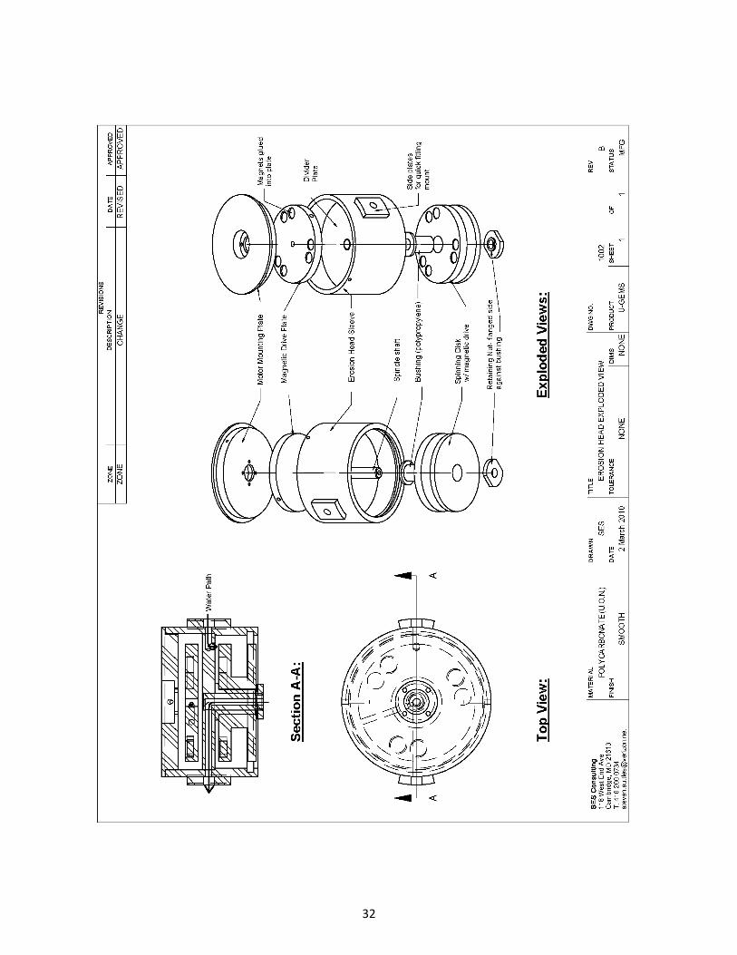
1.2.6 Erosion Heads
Erosion heads were designed and built at UMCES under the direction of Dr. Lawrence
Sanford. The erosion heads are primarily made of polycarbonate and use a magnetic drive
coupling to avoid any rotary seals (see drawing Section 7). The magnetic drive uses
0.500” x 0.200” Neodymium disc magnet pairs spaced at 120o. The rotating disk spins on
a delrin bushing that fits over a stationary central shaft with a bored hole in the middle to
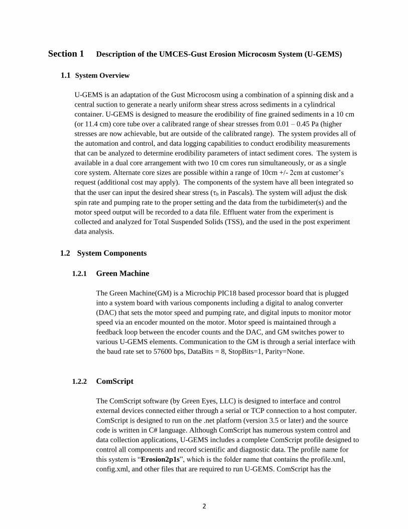
allow for the effluent water path. The water flows in on the side of the erosion head and
into a channel in the divider plate which enters the core tube on top of the spinning disk.
5
The water exits up through the central shaft and through another hole in the divider plate
and out of the opposite side of the erosion head. Quick connect fittings are used to allow
easy connection of the tubing to the erosion heads. The Maxon motor with the magnetic
drive plate is mounted to the top of the erosion head by way of a mounting plate attached
to the motor.
Figure 1.2.6.1- Photo of erosion head during experiment with flow pattern represented by
drawn lines and arrows.
1.2.7 Power/Control Box
The Power/Control box houses the GM/system board unit, the Maxon motor
controller(s), main 24 VDC power supply, DC/DC converter (12 VDC output), and
relay(s) to turn on/off motor controller(s) . There are connectors on the outside of this box
for A/C power in, a 4 amp fuse, RS232 serial connection to GM, RCA plug to pump
stroke rate controller, and 9 pin motor connector(s). When A/C power is supplied to the
box there is an electrical shock hazard. DO NOT TOUCH ANYTHING INSIDE THE
BOX when A/C power is connected. Use extreme caution!!
1.2.8 Accessories
A USB to serial converter is supplied with the system to allow multiple serial ports on a
computer with no on-board serial ports. Users will need to make sure the USB to serial

6
converter is configured correctly and that the COM port assignments match the
ComScript profile. Extruding pistons and extruding rod extensions are supplied to
extrude the core to the proper height below top of the core tube (10 cm). A clamp
mechanism is supplied to hold the erosion head securely to the core tube and a core
holder is supplied to hold and level the core(s) while running an experiment. Two cm
PVC disks with a central push pin are supplied to block out the sediment at the center of
the core where an artificially high pressure gradient exists from the proximity to the
effluent water intake at the bottom of the central shaft. Sample polycarbonate core test
chambers are supplied with the system.
7
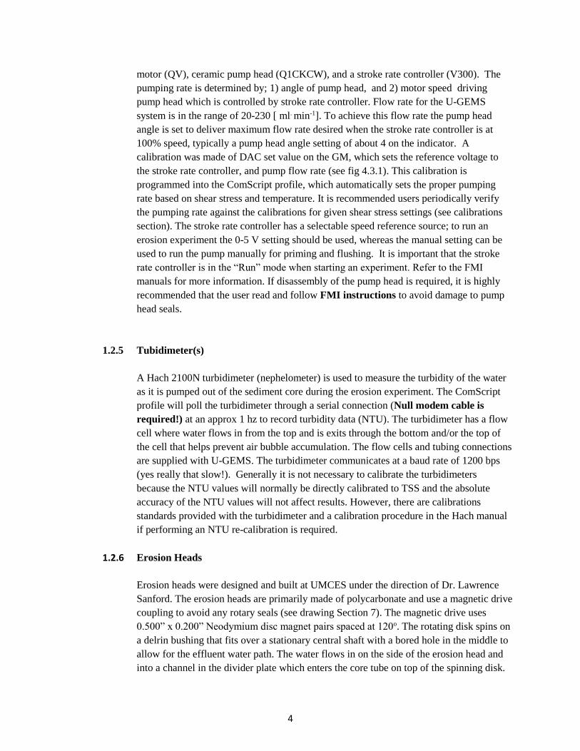
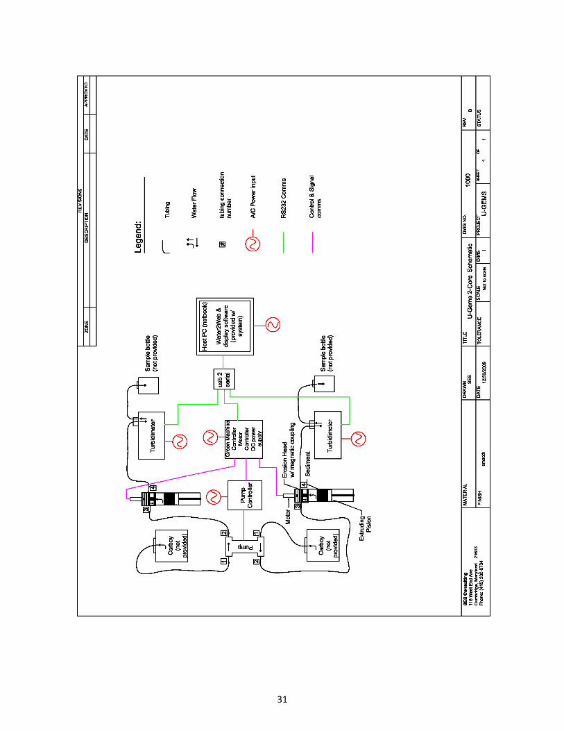
1.3 System Schematic
8
Section 2 System Operating Procedures
2.1 System Set-Up
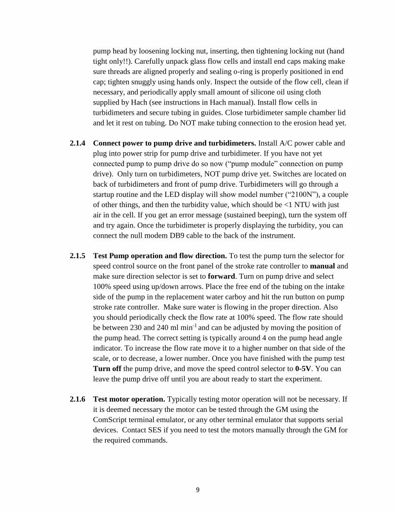
2.1.1 Unpack system components from the case to a suitable working surface. The
following components should be located on the bench top: turbidimeter(s), FMI
pump, FMI pump drive, Power/Control box (Green Machine, power supplies and
motor controllers), host computer (Lenovo x140e), USB to serial adapter. Note:
Arrange turbidimeter(s) and pump on bench top so that the tubing connections for
the water flow can be made with the length tubing supplied. Tubing length should
be minimized to reduce water flow path.
2.1.2 Connect power, signal, and communication cables. The motor, pump drive rca
cable, RS232 GM Comms cable (DB9 on 1 end and 9 pin Bulgin Buccaneer
connector on other), and A/C power supply cable connect to the outside of the
Power/Control box. Note: There is also a 4amp fuse in the fuse holder beside the
A/C power cable socket in the rear of the box. Connect opposite end of RS232
GM Comms cable to first COM port on USB to Serial converter. Connect
turbidimeter Null Modem cables (DB9) to second COM port on USB to Serial
converter, but Do Not connect to turbidimeter yet!! Connect RCA cable end with
RCA to double banana plug adapter to FMI pump drive 4-20mA input connector.
Note: User should verify that your COM port assignments are correct (see
Windows Device Manager). If they do not the ComScript profile that runs the
experiment might need to be modified. You can use ComScript terminal emulator
mode or other terminal programs (e.g. Procomm, Hyperterm, etc) to check COM
port assignments. See “Appendix B: COM Port Assignment Test w/ ComScript
Terminal Emulator” for a description of how to use ComScript terminal emulator
to check COM port assignments. See section 2.2.4 for making sure COM port
assignments are correctly set in the “profile.xml” file. Note: Cables have been
marked to help aid in proper hook-up.
2.1.3 Connect tubing and install flow cells. Remove tubing adapters from pump head
and disconnect adapters from storage tubing. Note: Trying to remove or install
tubing while adapters are connected to pump head could damage pump head, it is
therefore highly recommended that they be removed for connecting and
disconnecting from tubing. Install adapters onto tubing ends numbered 1 & 2. End
number 1 is intake side of pump and number 2 is outflow. Reinstall adapters onto
9
pump head by loosening locking nut, inserting, then tightening locking nut (hand
tight only!!). Carefully unpack glass flow cells and install end caps making make
sure threads are aligned properly and sealing o-ring is properly positioned in end
cap; tighten snuggly using hands only. Inspect the outside of the flow cell, clean if
necessary, and periodically apply small amount of silicone oil using cloth
supplied by Hach (see instructions in Hach manual). Install flow cells in
turbidimeters and secure tubing in guides. Close turbidimeter sample chamber lid
and let it rest on tubing. Do NOT make tubing connection to the erosion head yet.
2.1.4 Connect power to pump drive and turbidimeters. Install A/C power cable and
plug into power strip for pump drive and turbidimeter. If you have not yet
connected pump to pump drive do so now (“pump module” connection on pump
drive). Only turn on turbidimeters, NOT pump drive yet. Switches are located on
back of turbidimeters and front of pump drive. Turbidimeters will go through a
startup routine and the LED display will show model number (“2100N”), a couple
of other things, and then the turbidity value, which should be <1 NTU with just
air in the cell. If you get an error message (sustained beeping), turn the system off
and try again. Once the turbidimeter is properly displaying the turbidity, you can
connect the null modem DB9 cable to the back of the instrument.
2.1.5 Test Pump operation and flow direction. To test the pump turn the selector for
speed control source on the front panel of the stroke rate controller to manual and
make sure direction selector is set to forward. Turn on pump drive and select
100% speed using up/down arrows. Place the free end of the tubing on the intake
side of the pump in the replacement water carboy and hit the run button on pump
stroke rate controller. Make sure water is flowing in the proper direction. Also
you should periodically check the flow rate at 100% speed. The flow rate should
be between 230 and 240 ml min-1 and can be adjusted by moving the position of
the pump head. The correct setting is typically around 4 on the pump head angle
indicator. To increase the flow rate move it to a higher number on that side of the
scale, or to decrease, a lower number. Once you have finished with the pump test
Turn off the pump drive, and move the speed control selector to 0-5V. You can
leave the pump drive off until you are about ready to start the experiment.
2.1.6 Test motor operation. Typically testing motor operation will not be necessary. If
it is deemed necessary the motor can be tested through the GM using the
ComScript terminal emulator, or any other terminal emulator that supports serial
devices. Contact SES if you need to test the motors manually through the GM for
the required commands.
10
2.2 Software Set-Up
2.2.1 Software Overview. ComScript software, developed by Green Eyes, is supplied
to run U-GEMS experiments. ComScript is written in C# using the .net platform.
Latest version of ComScript software maybe downloaded at:
http://gescience.com/ComScript.html
A ComScript license is included with your UGEMS system. Your license key has
already been registered with Green Eyes, LLC. However, if ever necessary you
can receive a license key by starting the ComScript program
(ComScriptGUI.exe), generate a license key under the help tab in the Desktop
Utility, and provide to Green Eyes, LLC to receive activation key. The activation
key to specific to the computer. For the Lenovo x140e notebook computer
supplied with you system the activation key is;
EE6B-3262-CAC9-29BE
Version 3.5 or later of Microsoft .net platform must be installed on the host
computer to run ComScript. Most newer computers come with .net pre-installed,
but if required can be downloaded for free at from Microsoft website.
Presently ComScript is designed to run on PCs running Windows Operating
Systems. It has been primarily tested on PC running Windows XP, Windows7,
and most recently Windows8. ComScript includes both a terminal emulator and
an automatic mode that runs a “profile” script that is written in a user friendly xml
format. The xml command scripting language is a powerful tool to write
applications for controlling external devices and collecting and storing data. The
scripting language was used to write the “profile” and “config” xml files that run
the erosion experiments. The open source shareware program, “gnuplot”, is also
used to make the “on the fly plots” of turbidity during the experiments. Gnuplot
must also be installed on the host PC. Gnuplot can be downloaded at:
http://sourceforge.net/projects/gnuplot/files/
11
2.2.2 Software installation. It is important to preserve the directory structure otherwise
there will need to be some modifications to the programs for everything to
function properly. ComScript should be installed in the root of the hard drive, if at
all possible in “C:\ComScript\”. Contact SES or Green Eyes LLC to get
registration key for ComScript (if not already registered) so that you will be using
a licensed version (included with U-GEMS) otherwise trial version will expire in
30 days. To launch the ComScript application, start the application “ComScript
GUI.exe”. Make a shortcut and paste onto the desktop for convenience. The
“profiles” folder is located under “C:\ComScript\” and your project folder should
be located in the “profiles” folder (e.g. “C:\ComScript\profiles\Erosion2p1s”).
The gnuplot program executable should be located in the “C:\gnuplot\binary\”
folder otherwise the .plt files in the erosion profile folder will need to be
modified. The gnuplot program will be called directly from the erosion profile so
users only need to make sure everything is in the right place. There is a file called
“gnuplotkill.bat” that is called by the profile that needs to be in the erosion profile
folder. If you would like to modify the plots the .plt files can be edited. A profile
editor tool is built-in to the ComScript Desktop Utility, which has some useful
tools to help build and edit profile and config xml files. A shareware program
called “ConTEXT”, is also a useful text editor that recognizes xml tags and is
helpful for editing the profile or config file for your erosion applications.
ConTEXT can be downloaded at: http://www.contexteditor.org/downloads/ .
2.2.3 Preparing to run program. Start the ComScript application and select the your
“Erosion” profile from drop down box for your application; e.g. “Erosion”. Check
“Open Data Interface when profile begins” box (see fig 2.2.1).
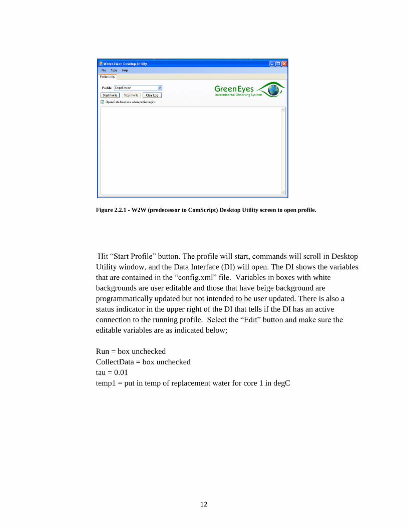
12
Figure 2.2.1 - W2W (predecessor to ComScript) Desktop Utility screen to open profile.
Hit “Start Profile” button. The profile will start, commands will scroll in Desktop
Utility window, and the Data Interface (DI) will open. The DI shows the variables
that are contained in the “config.xml” file. Variables in boxes with white
backgrounds are user editable and those that have beige background are
programmatically updated but not intended to be user updated. There is also a
status indicator in the upper right of the DI that tells if the DI has an active
connection to the running profile. Select the “Edit” button and make sure the
editable variables are as indicated below;
Run = box unchecked
CollectData = box unchecked
tau = 0.01
temp1 = put in temp of replacement water for core 1 in degC

13
Figure 2.2.2- Data Interface window with sample of properly initialized values to begin erosion
experiment.
Then hit “Update” to make changes take effect and then “Save” button
(important!). This will save your parameters to the config.xml file. Next stop the
profile, “Stop Profile” button in Desktop Utility and close the DI window.
ComScript has been initialized.
2.2.4 Make sure the COM ports are set correctly. Open “profile.xml” file from the
folder with your application; e.g. C:\ComScript\profiles\Erosion2p1s\profile.xml,
in ComScript profile editor, ConTEXT or other editor. Make sure the COM ports
are correctly assigned for the “GreenMachine”, “Turb1”, and “Turb2” (if dual
core system). If they are not change “port” setting of the “device” command to the
correct COM port assignment; e.g. “COM1”. If corrections are required be sure to
save those corrections before running the ComScript profile. See section 2.1.2 and
Appendix B for more information on testing COM port assignments.
2.2.5 Move/Rename/Delete old Datafile and log files. Data from the experiment will
be written to the file “Datafile.txt” in the folder with the “profile” you are
running. If the file exists the data will be appended to it, if it does not exist it will
be created. So prior to starting an experiment, users are advised to either

14
Move/Rename/Delete the existing “Datafile.txt” to start with a fresh file. Very
Important!!! Once experiment is complete, rename and archive “Datafile.txt” for
your experiment to avoid accidently deleting it when you start the next
experiment. There is also a file called “log.txt” this file is a record of all the
command processing of the ComScript profile, and is primarily a diagnostic tool.
Normally writing to log file will be turned off. However if the set command in
“startup” script in profile is set to “true” this file will be recorded and if left alone
this file will becoming very large, so we highly recommend it be either archived
or deleted after each experiment if it is recorded (not default).
2.2.6 Prepare the cores and start the experiment. See sections 2.3 & 2.4.
2.2.7 There is a ComScript profile command manual that is accessible from the help tab
of the Desktop Utility.

15
2.3 Core Prep
2.3.1 Core selection and extrusion. Try to select cores where the sediment surface is
as even as possible. Carefully extrude cores using the pistons provided. It is
helpful to apply silicone grease liberally to piston o-ring prior to pushing into the
bottom of the core. Extrude the sediment surface to an average distance of 10 cm
from the top of the core tube. Tighten nut on the piston such that the o-ring makes
a seal with core tube. Install ¾” threaded PVC rod extensions as needed, and
thread the bottom plate until flange just touches the bottom of core tube. Install
the diamond plate on ¾” threaded PVC rod that is protruding below bottom plate
(see fig 2.3.1).
2.3.2 Place core(s) in core holder. Install the core into the core holder, level and
secure the core using 4 positioning screws in each core holder position. Position
the center block out disk (provided) in the center of the sediment, push pin into
sediment, and make flush with the sediment surface. Needle nose pliers can be
used to install the center block out disk. The water level should be at or near top
of core tube. If the level is low carefully, add replacement water collected at
coring site, taking care not to disturb the sediment surface.
2.3.3 Install erosion head. Once the core is level and secure in core holder, install the
erosion head. Make sure the erosion head is assembled correctly, such that the
disk spins freely by hand (Important!!). Apply a small amount of silicone grease
around top of core tube and position erosion head over core such that the o-ring in
the erosion head contacts the top of the core evenly. Standing directly over the
core and using your legs to secure the core holder, alternating pushing down on
one side of the erosion head then the other with steady firm pressure. The erosion
head should move down the core, and some water will come out of the ports as it
moves into position. The divider plate in the middle of the erosion head should
just contact the top of the core tube. Use gentle pressure to seat the erosion head
to the core tube to avoid compromising the sealed perimeter of the divider plate to
the erosion head sleeve.
2.3.4 Install motor on erosion head. Now that the erosion head is in position, install
the motor with the magnetic drive plate and erosion head top attached to the
motor. Align one of the holes in the erosion head top plate and insert the nylon
screw and hand tighten. The second nylon screw may be installed, but if the hole
does not align properly it may be omitted.
16
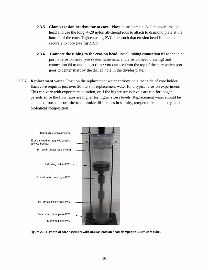
2.3.5 Clamp erosion head/motor to core. Place clear clamp disk plate over erosion
head and use the long ¼-20 nylon all-thread rods to attach to diamond plate at the
bottom of the core. Tighten using PVC nuts such that erosion head is clamped
securely to core (see fig 2.3.1).
2.3.6 Connect the tubing to the erosion head. Install tubing connection #3 to the inlet
port on erosion head (see system schematic and erosion head drawing) and
connection #4 to outlet port (hint: you can see from the top of the core which port
goes to center shaft by the drilled hole in the divider plate.)
2.3.7 Replacement water. Position the replacement water carboys on either side of core holder.
Each core requires just over 20 liters of replacement water for a typical erosion experiment.
This can vary with experiment duration, or if the higher stress levels are run for longer
periods since the flow rates are higher for higher stress levels. Replacement water should be
collected from the core site to minimize differences in salinity, temperature, chemistry, and
biological composition.
Figure 2.3.1- Photo of core assembly with UGEMS erosion head clamped to 10 cm core tube.
17
2.4 Running Erosion Experiment
2.4.1 System ready. Make sure power is supplied to the Power/Control box (A/C cord
plugged in, fuse good and installed). The turbidimeter(s) are on and displaying
the turbidity value. The pump drive is on, the pump module connected, and the
speed selector set to “0-5V”. The serial cable is plugged into the Power/Control
box, null modem cables to turbidimeter(s), and each into the USB to Serial
converter where port assignments have been verified.
2.4.2 Core Ready. The core is extruded, the center block out is installed, the erosion
head/ motor is installed and clamped to the core, the tubing connections are made
and the replacement water is in place. Water level in core is at or near top of core.
Intake tubing is in replacement water, and sample bottles are in place to collect
effluent water.
2.4.3 ComScript ready. Both ComScript and gnuplot are installed. The directory
structure matches ComScript profile and plt files. Start the ComScript application
(“ComScript GUI.exe”). Select the correct “profile” from the drop down menu for
your application, e.g. “Erosion2p1s”. Check “Open Data Interface when profile
begins” box (see fig 2.2.1).
2.4.4 Water temperature and sample. Record the water temperature and take a
sample of the replacement water for TSS analysis. Ready the sample bottles used
for water collection during the experiment.
2.4.5 Start Profile. Hit “Start Profile”. Make sure commands are scrolling in Desktop
Utility window and that DI opens and shows status as “Connected”.
2.4.6 Start experiment. In the DI window select “Edit”. Make sure tau = 0.01, and the
temp1 = measured water temp in degrees Celsius (oC). (Note: for 2 core system
there is both temp1 and temp2, and the program uses the average of the two to
determine settings to achive set shear stress ()). Check “Run” and “Data Collect”
boxes, then select “Update” button. TURN on PUMP now! You have now
initiated the experiment. The motors should start spinning slowly and the pump
should start turning slowly. Verify this is happening. Also note the time of the
start of the experiment. The data interface window will show the time stamp, the
total elapsed time for the experiment (etime) in seconds, and the total elapsed step
time (stime) in seconds. These times are helpful in determining step changes and
noting times of observed events. Optional: hit the save button to write the data
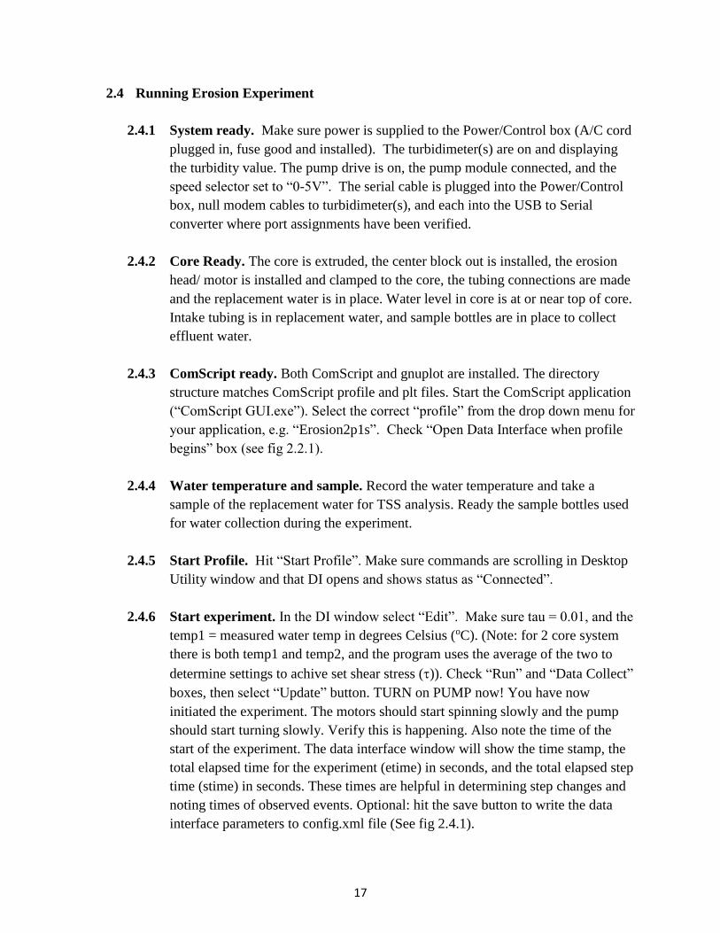
interface parameters to config.xml file (See fig 2.4.1).
18
Figure 2.4.1 – W2W (similar for ComScript) erosion profile Data Interface when ready to start
experiment. Select “Update” to initiate experiment.
2.4.7 Open Image Watcher. From the tools menu in the Desktop Utility select “Image
Watcher”. In the Image Watcher window select “Choose Image” and then select
image file “W2Wtest.png” from your profile directory (see fig 2.4.2). If you
started with a fresh “Datafile.txt” file the plot should show the plot of turbidity
and motor speed from the time the experiment was started by checking the “Run”
and “Data Collect” boxes, see fig 2.4.3 (note: If the data file still contained data
from a previous experiment then that data will also display on the plot). The x-
axis range on the plot is 1800 seconds so that it will scroll to a new plot every 30
minutes of elapsed time during the experiment. If it becomes necessary to restart
an experiment the elapsed time counter will be reset and will only reflect the time
since the experiment was restarted and the plot will overlap the previous data. In
this case be sure to use the time stamp (column 1) in the “Datafile.txt” to
determine elapsed and step time for post-processing. Arrange the windows on
your desktop so that you can see the data interface, image watcher, and
ComScript desktop utility.

19
Figure 2.4.2 - Opening Image Watcher and selecting image file.
Figure 2.4.3 - Image Watcher plot for single core system near start of experiment.
20
2.4.8 Mark time of water into sample bottle. Mark the time that the water starts to
flow into sample collection bottles. Use log sheets for each Core (see Appendix
A). This first step is called the flushing step. No erosion is expecting and there
should be a general clearing of the water. Check the Image Watcher to view the
time series of turbidity and keep an eye on the water level in the core tube. It
should be up to near the top of the core tube and should never be allowed to fall as
low as the bottom of the spinning disk. If the water level is low you can swap the
tubing connections #3 & #4 on the erosion head to allow it to fill and then switch
them back (important!) once the water level corrected.
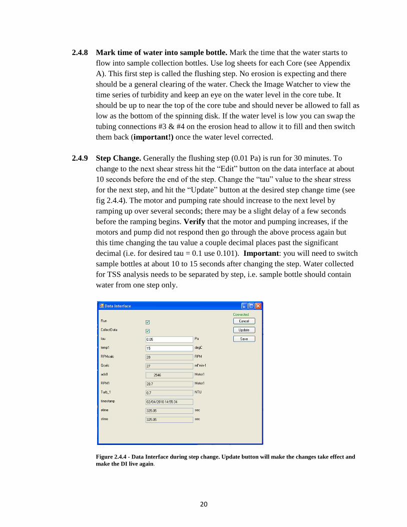
2.4.9 Step Change. Generally the flushing step (0.01 Pa) is run for 30 minutes. To
change to the next shear stress hit the “Edit” button on the data interface at about
10 seconds before the end of the step. Change the “tau” value to the shear stress
for the next step, and hit the “Update” button at the desired step change time (see
fig 2.4.4). The motor and pumping rate should increase to the next level by
ramping up over several seconds; there may be a slight delay of a few seconds
before the ramping begins. Verify that the motor and pumping increases, if the
motors and pump did not respond then go through the above process again but
this time changing the tau value a couple decimal places past the significant
decimal (i.e. for desired tau = 0.1 use 0.101). Important: you will need to switch
sample bottles at about 10 to 15 seconds after changing the step. Water collected
for TSS analysis needs to be separated by step, i.e. sample bottle should contain
water from one step only.
Figure 2.4.4 - Data Interface during step change. Update button will make the changes take effect and
make the DI live again.
21
2.4.10 Steps. Steps other than the flushing step are typically run for 20 minutes. A
typical step series would be 0.01 (flushing), 0.05, 0.10, 0.15, 0.20, 0.30, and
0.45 Pa. If desired additional step(s) up to 0.60 Pa can be run, but are outside of
the range of the Gust calibrations presently. Select the ”Edit” button about 10
seconds before the desired step change, edit tau, hit “Update” button at time of
desired step change to initiate step change. Make sure the motor and pump speeds
are increasing, and switch sample bottles. Optional: Hit “Save” button in the data
interface, so in the event of a ComScript or PC failure you will be able to make a
quick recovery and save your experiment.
2.4.11 Datafile. Data will be written to “Datafile.txt” when “Data Collect” box is
updated to “checked”. Check that the file size is increasing to verify data is being
written, but Do Not open the file with MSExcel or similar program while
experiment is running or a file lock-up and ComScript crash may result. The
format for the datafile.txt is;
"timestamp,etime,stime,RPM1,Turb_1,RPM2,Turb_2"
There is no header line written and the file is comma delimited.
2.4.12 Monitoring ComScript. Keep an eye on the Data Interface Window and to
verify that it is “connected” and the numbers are changing as expected (e.g.
etime). Although unlikely, should the profile stop, you will need to take the
following actions:
select the “save” button in the DI window
select the “Stop Profile” button in the Desktop Utility
close DI window
make sure “Open Data Interface when profile begins” box is
checked in Desktop Utility
select “Start Profile” in the Desktop Utility
In DI select “Edit” check “Run” and “CollectData” boxes and hit Update
button.
The program should start running again. Make sure tau is set to the correct value
and if Data Interface variables were not saved when it crashed tau mat need to be
reset. The etime and stime will be incorrect now since they will reflect the time
22
since the program was restarted. Reopen Image Watcher (see sec 2.4.7).
2.4.13 End of experiment. When the last step is completed, go to DI window and select
“Edit” change “Run” and “Data Collect” to boxes to “unchecked”, and select
“Update”. The system tau value will automatically change to 0.01 Pa and the
motor and pump should wind down. The motor will automatically turn off, but the
pump should be turned off manual at the V300 stroke rate controller. Experiment
is over!!! Once the system has shutdown in the DI window select “Save” to write
parameters to config file so that they will be set correctly for next experiment. In
Desktop Utility select “Stop Profile”, the DI window should now be
“disconnected” from the profile.
2.4.14 Archive datafile. Rename “datafile.txt” and move to location for archiving. Keep
data safe and backed up. If recorded either rename, and move “log.txt” file for
archiving or delete so the file will not grow too large.
2.4.15 Clean & Store. Disconnect tubing connections from the erosion heads. Run clean
water through the pumps to clean pump heads for 2 minutes, using manual pump
operation (see System Setup). Turn off all devices and disconnect A/C power.
Remove motors and erosion heads from cores. Remove the center block out disk
from sediment (may be covered over by sediment). Dump the sediment or dispose
of it as required. Clean the erosion head with clean water and take apart spinning
disk by removing polycarbonate nut. Be careful not to drop. Be sure to reinstall
the flanged delrin bushing and make sure the nut is oriented correctly when
reassembling so that the disk spins freely (see drawing section 7). Remove the
flow cells from turbidimeters (Note: sometimes the bottom end cap will catch on
the plastic holding arm in the sample chamber of the turbidimeter. If this happens
you can try wiggling it around to get it free or sometimes it will be necessary to
place a thin object straight down beside the flow cell on the front side of the flow
chamber to hold the plastic arm back so that the flow cell can get by). Flush the
tubing and flow cells with clean water (de-ionized if available). Allow to dry if
possible. Wrap the flow cells in Kimwipes and put them back in styrofoam
packaging for safe storage. Disassemble the system and put back in storage/travel
case.
23
Section 3 System Maintenance
3.1 General
Any non-electronic parts of the system that comes in contact with salt water or sediment
should be rinsed thoroughly after use with clean fresh water. Electronic parts should be
wiped done carefully and/or gently cleaned with compressed air. Most of the
components require little or no regular maintenance, just proper care.
3.2 Power/Control Box
The Green Machine and associated electronics should be stored away from extreme
temperatures and high humidity. There is no regularly scheduled maintenance necessary
of the components in the box other than making sure all components are well secured in
the box especially when transporting (see Power/Control box layout drawing in section
7). The large power supply should be blocked in with foam when transporting. If an
electrical component should fail, replacement of that component will likely be the best
course of action. If an electrical connection should come loose or if a connector break
then a simple repair or new connector would be required. There is a 4A fuse in the rear
of the box. A replacement fuse is provided with the box, but if additional fuses are
required they should be readily available (see parts list for info). When transporting the
P/C box it should be protected from rough handling and it may be necessary to block in
the larger power supply with foam blocks or padding to prevent it from bouncing on the
electrical panel.
3.3 Motor
Maxon Precision motors require very little maintenance. If the motor contacts salt water
during an experiment, the motor should be carefully wiped down with a damp (fresh
water) cloth and gently blown dry with air while disconnected from the P/C box. If any
major problem occurs with the motor, it should be sent to SES Consulting or Maxon for
repair. Wiring connections on end of motor (inside PVC housing) are extremely fragile
and if it becomes necessary to remove the PVC housing to expose the connections care
must be taken as to not damage the solder tabs on the motor. Wiring problems involving
the motor controller or the cord to the motor are fairly simple and can be repaired by
someone with knowledge of electronics and soldering. Motors should be stored in the
case provided and kept in a dry environment free of temperature extremes to provide
longest the possible service life.
3.4 Pump
Maintenance of the FMI pump is simple but very important. Always rinse the pump
heads thoroughly after use by pumping fresh water though the system. Never run
the pump heads dry. If only one pump head is being used, a short loop of tubing filled
with fresh water should be placed on the pump head not in use. When storing the pump,
it is recommended to keep the pump heads moist. Short loops of tubing filled with fresh
24
water can be placed on the pump heads during storage. If this is not done, the pump
heads may seize up. The best way to free a seized pump head is to rinse it with fresh
water. The easiest way to do this is to remove the pump head from the pump (illustrated
in pump manual) and soak the pump head in fresh water. If the seized pump head cannot
be removed from the pump it may be necessary to squirt fresh water into the isolation
gland (small ports on side of pump head) and anywhere else possible to rinse the seized
piston within the pump head. With a little luck this should free the pump head enough to
remove it from the pump and soak it. After reinstalling the pump head, the flow setting
of the pump should be double checked (see section 2.1.5.). Pump calibrations should be
checked periodically to insure proper settings are maintained. Normally, checking the
flow rate at the 100% setting on the stroke rate controller will suffice. If a problem is
suspected or verification is required it might be necessary to do a full calibration. One
way this can be done is by setting up the system in the lab using clean water w/o
sediment (using pistons as bottom and running through each step (shear stress) and
checking the flow rate). This can be done relatively quickly since each step only needs to
be long enough to test the pumping rate. You can use the equations in section 4 to
determine what the pumping rate (Q) should be for each step using shear stress (τb) and
temperature (T). If the pumping rate is off by more than 5% on average then this may
indicate the need for a new calibration or a problem with the pump or a pump head that
needs to be resolved. Contact SES for further assistance.
3.5 Turbidimeter
Any part of the turbidimeter sample chamber that comes in contact with salt water or
sediment should be gently rinsed with fresh water, taking care to not splash any of the
electrical parts of the unit. If this is necessary be sure unit is unplugged from A/C
power source. Particular care should be taken with the flow through cell to keep it free
of deposits, finger prints, and scratches. Periodically the flow cells should have silicone
oil applied with the cloth provided following the instructions in the Hach manual.
Calibration standards are provided with the turbidimeters if a NTU calibration is needed.
Typically, this is not required for the erosion system because a calibration to Total
Suspended Solids (TSS) is normally made from the filter data of the collected sample
water; however, consult the Hach manual for the calibration procedure if a NTU
calibration is deemed necessary. When not in use, the turbidimeter should be stored
away from temperature extremes and high humidity.
3.6 Erosion Head
The erosion head should be taken apart and rinsed thoroughly between erosion
experiments and before long term storage. The o-ring that provides the seal between the
erosion head and the core tube may need replacement periodically. This o-ring is a Dash
No. 242 (for 4” core tube size), standard buna o-ring, which is readily available from
industrial suppliers (e.g. McMaster-Carr). It is likely that the neodymium magnets on the
spinning disk/spool will start to show some rust. Small amounts of rust should not be a

25
problem, however if the rust gets heavy and there is the potential for the rust to flake off
during an experiment and get sucked in through the turbidimeter, it should be sanded
lightly and recoated with an epoxy or urethane coating, if necessary you can send them
back to SES to replace/ re-seal magnets. The glued on pieces on the sides of the erosion
heads (side plates), where the quick connect fittings screw in, should be inspected for
leaks periodically. If a leak is detected the piece should be re-glued/sealed. The divider
plate that separates the wet-side of the magnetic coupling from the dry could also
develop a leak, where water from the core tube would get above the plate on the motor
(dry) side. If water is getting on top of this plate this indicates a leak either around the
perimeter of the divider plate or around the spindle shaft for the spinning disk. If there is
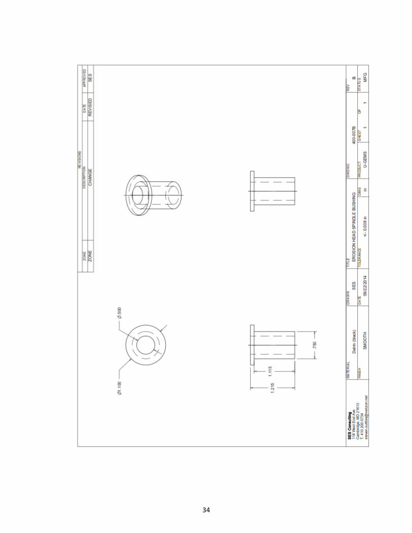
a leak re-seal the offending area. Except for the bushing (acetal/Delrin) the erosion head
is made of durable polycarbonate and should provide a long service life. Note: When re-
assembling erosion heads be sure bushing, nut, and spinning disk are installed correctly,
and disk spins freely (see Erosion Head drawing in section 7). The delrin bushing may
need replacement during the service life of the erosion head(s). If this becomes
necessary contact SES Consulting or have a bushing fabricated to replace (see drawing
in Section 5).
26
Section 4 Calibrations and Settings
4.1 Gust Calibrations. A key feature of this system is the combination of the rotating disk
and central suction that generates a quasi-uniform shear stress across the surface of the
sediment. These calibrations were made in Dr. Gust’s laboratory and he has patented this
concept (US patents 4,884,892 and 4,973,165). The calibrations were made using the standard
10cm core erosion head, with spinning disk 10 cm above the sediment surface.
To obtain the desired applied shear stresses, specific combinations of motor RPM and pumping
rate must be applied. These combinations are determined from calibration equations derived
from experimental testing in the laboratory of Dr. Gust in Germany. The calibration equations
are expressed in terms of the shear velocity at a water temperature of 15 ⁰C, where the shear
velocity is defined by 𝒖∗ = √𝝉𝒃 𝝆⁄ , τb is the bottom shear stress and ρ is the water density. The
most recent calibration equations for the 10 cm microcosm are:
𝒖∗𝟏𝟓 = 𝟎. 𝟎𝟑𝟏𝟖 ∙ 𝒏𝟎.𝟕𝟔𝟑
𝑸 = −𝟐𝟖. 𝟑𝟏 ∙ 𝒖∗𝟏𝟓𝟐 + 𝟏𝟕𝟎. 𝟐 ∙ 𝒖∗𝟏𝟓 − 𝟐𝟑. 𝟖𝟓
Where u*15 is in cm sec-1, n is the disk rotation rate in rotations per minute (RPM), and Q is the
pumping rate in ml min-1. To convert to shear velocity at temperature T to equivalent u*15, Dr.
Gust’s lab recommends
𝒖∗𝟏𝟓 = 𝒖∗𝑻 ∙ (𝟏 + 𝟎. 𝟎𝟎𝟔 ∙ (𝑻 − 𝟏𝟓))
and then the stress is 𝝉𝒃 = 𝒖∗𝑻𝟐 ∙ 𝝆. The maximum calibrated shear stress at present is 4.5 dynes
cm-2 (0.45 Pa), though we have pushed the system to 6.0 dynes cm-2 (0.60 Pa) by extrapolation.
These calibrations have been programmed into the W2W profile.xml program so that when the
user sets the shear stress (units of Pascals [Pa]) and temperature the required RPM and pumping
rate (Q) are calculated
4.2 Maxon Motors. The Maxon motor controller (LSC 30/2) has been set for the proper
operation in the erosion system and a speed calibration was performed so that the
relationship of the motor output speed and the encoder counts could be established.
These setting should not require change unless a new motor controller is installed and
needs to be configured or the settings have inadvertently changed on the existing units.
27
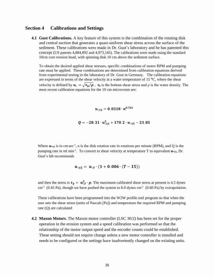
The motor calibration was performed using visual count of 10 revolutions of the
magnetic drive plate attached to the motor output shaft and recording the time. The
reading of the encoder counts of ChanA on a digital input on the Green Machine (GM)
was also recorded. This visual calibration was possible up to an output shaft RPM of just
under 100, above which visually counting RPM was not reliable. The results of the
calibration of the motor can be found in figure 4.1.1.
Figure 4.2.1- Maxon motor calibration for GMariotti_LSU single core system. Calibration date
was 7 June 2015.
The encoder is attached to the motor on the opposite end of where the gearhead is
attached. The encoder therefore spins at the motor base speed and not at the same speed
as the gearhead output shaft which the magnetic drive disk is mounted. Parameters of
how the encoder counts where collected and the motor configuration are shown below;
Enocder is 500 counts per turn with 2 channels (A & B). Each channels has
1,000 transitions (state changes) per turn.
Only Channel A was used.
Counts were collected nearly continuously using 4 millisecond duration.
Running sum of 20, 4 ms samples were used for reported encoder reading.
Gear reduction for output shaft of motor = 18:1
These calibration yield the following result which is confirmed by the visual calibration
result;
𝑹𝑷𝑴 (𝒐𝒖𝒕𝒑𝒖𝒕) = 𝟎. 𝟎𝟑𝟖𝟒 ∙ 𝑬𝑵𝑪
y = 0.0384xR² = 0.9998
0
50
100
150
200
250
300
350
400
450
500
0 5000 10000
Mo
tor
RP
M
Encoder (counts ChanA 4ms sum of 20)
Visual
Visual
Linear (Visual)
28
To configure the motor controller the dip switches need to be set for encoder operation
and for external speed control of +/- 3.9 Volts, and the potentiometers (P1 – P5) need to
be adjusted so that the motor does not spin at 0 reference voltage and that the maximum
desired motor speed is achieved at max reference voltage. See Maxon Motor Controller
(LSC 30/2) manual for more information and location of dip switches and
potentiometers. Please note this is not a routine requirement, but only when configuring
a new controller or when reconfiguration is required. The maximum motor output shaft
speed for this motor assembly (p/n# 333189) is 376 RPM ( ENC = 9800).
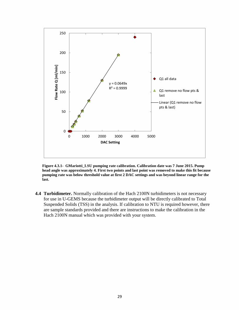
4.3 FMI Pump. The FMI pump (QV w/ Q1CKCW pump head) was calibrated so that the
maximum flow rate could be achieved and the relationship of DAC setting to pumping
rate could be found. This relationship was programmed into the ComScript profile.xml
file so that the GM would send the proper analog reference voltage to the V300 stroke
rate controller that controls the pumping rate. The calibration yielded the following
results;
𝑸 = 𝑫𝑨𝑪 ∙ 𝟎. 𝟎𝟔𝟓
First the pump heads were set to achieve maximum desired flow rate (Q= 240 ml . min-1)
when the stroke rate controller was set to 100%. This was achieved with pump head
angle at 4 on the angle indicator plate. Then a flow calibration was performed over a
complete range of DAC settings on the GM where the corresponding flow rate was
measured by collecting water over a 1 minute interval and measuring the volume.
The DAC setting has a range of 0 to 4095 which converts to an analog output voltage
range of 0-5 volts. This gives a DAC setting to voltage ratio of 4095:5.
The DAC set value is calculated in the ComScript profile.xml, based on the shear stress
setting and is sent to the GM which sends the appropriate reference voltage to the V300
Stroke Rate Controller, which controls the pumping rate.
29
Figure 4.3.1- GMariotti_LSU pumping rate calibration. Calibration date was 7 June 2015. Pump
head angle was approximately 4. First two points and last point was removed to make this fit because
pumping rate was below threshold value at first 2 DAC settings and was beyond linear range for the
last.
4.4 Turbidimeter. Normally calibration of the Hach 2100N turbidimeters is not necessary
for use in U-GEMS because the turbidimeter output will be directly calibrated to Total
Suspended Solids (TSS) in the analysis. If calibration to NTU is required however, there
are sample standards provided and there are instructions to make the calibration in the
Hach 2100N manual which was provided with your system.
y = 0.0649xR² = 0.9999
0
50
100
150
200
250
0 1000 2000 3000 4000 5000
Flo
w R
ate
Q [
ml/
min
]
DAC Setting
Q1 all data
Q1 remove no flow pts &last
Linear (Q1 remove no flowpts & last)

30
Section 5. Drawings
31
32
33
34

35
Section 6. Parts List
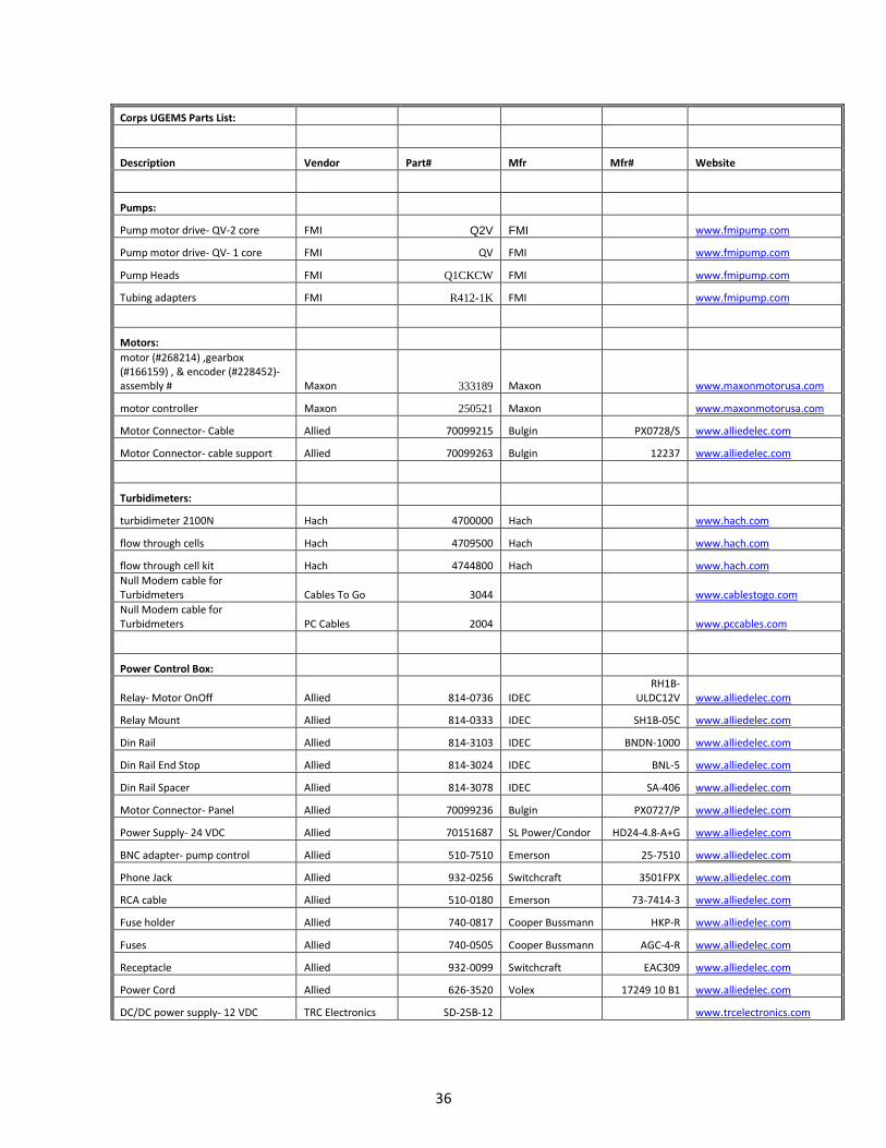
36
Corps UGEMS Parts List:
Description Vendor Part# Mfr Mfr# Website
Pumps:
Pump motor drive- QV-2 core FMI Q2V FMI www.fmipump.com
Pump motor drive- QV- 1 core FMI QV FMI www.fmipump.com
Pump Heads FMI Q1CKCW FMI www.fmipump.com
Tubing adapters FMI R412-1K FMI www.fmipump.com
Motors:
motor (#268214) ,gearbox (#166159) , & encoder (#228452)- assembly # Maxon 333189 Maxon www.maxonmotorusa.com
motor controller Maxon 250521 Maxon www.maxonmotorusa.com
Motor Connector- Cable Allied 70099215 Bulgin PX0728/S www.alliedelec.com
Motor Connector- cable support Allied 70099263 Bulgin 12237 www.alliedelec.com
Turbidimeters:
turbidimeter 2100N Hach 4700000 Hach www.hach.com
flow through cells Hach 4709500 Hach www.hach.com
flow through cell kit Hach 4744800 Hach www.hach.com
Null Modem cable for Turbidmeters Cables To Go 3044 www.cablestogo.com
Null Modem cable for Turbidmeters PC Cables 2004 www.pccables.com
Power Control Box:
Relay- Motor OnOff Allied 814-0736 IDEC RH1B-
ULDC12V www.alliedelec.com
Relay Mount Allied 814-0333 IDEC SH1B-05C www.alliedelec.com
Din Rail Allied 814-3103 IDEC BNDN-1000 www.alliedelec.com
Din Rail End Stop Allied 814-3024 IDEC BNL-5 www.alliedelec.com
Din Rail Spacer Allied 814-3078 IDEC SA-406 www.alliedelec.com
Motor Connector- Panel Allied 70099236 Bulgin PX0727/P www.alliedelec.com
Power Supply- 24 VDC Allied 70151687 SL Power/Condor HD24-4.8-A+G www.alliedelec.com
BNC adapter- pump control Allied 510-7510 Emerson 25-7510 www.alliedelec.com
Phone Jack Allied 932-0256 Switchcraft 3501FPX www.alliedelec.com
RCA cable Allied 510-0180 Emerson 73-7414-3 www.alliedelec.com
Fuse holder Allied 740-0817 Cooper Bussmann HKP-R www.alliedelec.com
Fuses Allied 740-0505 Cooper Bussmann AGC-4-R www.alliedelec.com
Receptacle Allied 932-0099 Switchcraft EAC309 www.alliedelec.com
Power Cord Allied 626-3520 Volex 17249 10 B1 www.alliedelec.com
DC/DC power supply- 12 VDC TRC Electronics SD-25B-12 www.trcelectronics.com

37
Enclosure-QR Latch OPQ CVR GRY 4x Hinge 14x12x6in AutomationDirect
HW-J141206CHQR Hubbell www.automationdirect.com
SUB-PANEL Aluminum FITS 14X12IN2 AutomationDirect HW-MP1412A Hubbell www.automationdirect.com
ErosionHead/Plumbing/etc:
Inline Tube connection- straight, insert-barb 3/16" I.D. tubing QuickCouplings PMC2203 CPC PMC2203 http://quickcouplings.net/
Quick Disconnect- 1/8" NPT fitting, 1/8" flow straight QuickCouplings PMC1002 CPC PMC1002 http://quickcouplings.net/
Inline Tube connection- straight, insert-barb 3/16" I.D. tubing US Plastics 64622 CPC www.usplastic.com
Quick Disconnect- 1/8" NPT fitting, 1/8" flow straight US Plastics 64601 CPC www.usplastic.com
Tygon tubing- 3/16" I.D. x 7/16" O.D. US Plastics 57108 Tygon www.usplastic.com
Tygon tubing- 1/8" I.D. x 1/4" O.D. US Plastics 57105 Tygon www.usplastic.com
3/4" -10 threaded PVC rod Piedmont Plastics www.piedmontplastics.com
1/4"- 20 nylon threaded rods McMaster-Carr 98743A230 www.mcmaster.com
3/8"- 16 treaded studs (pkg of 10) McMaster-Carr 92412A640 www.mcmaster.com
erosion head o-ring (Dash No. 242, buna std) McMaster-Carr 9452K192 www.mcmaster.com
Neodymium disc magnets .500 x .200 Magnet Source ND-140N-35 www.magnetsource.com
USB to Serial converter Moxa UPort 2210 MOXA UPort 2210 http://www.moxa.com/
Carry Case CarryCasesPlus iM3075-F Storm iM3075-F www.carrycasesplus.com

38
Appendix A:
Sample Erosion Experiment Log Sheet

39
Erosion log sheet
Experiment Name: Date:
Experiment Start Time ( ): Operator:
Step
, [Pa]
Bottle
No.
Step start
time
Bottle switch
time
Notes

40
Appendix B:
COM Port Assignment Test w/ ComScript Terminal Emulator

41
Procedure for testing COM Port Assignments using ComScriptTerminal Emulator:
1. Start ComScript and Open Terminal Emulator Program from Menu.
Figure B.1- Opening Terminal Emulator in W2W (predecessor to ComScript)Desktop Utility.
2. Configure Connection for Green Machine and Connect.
Figure B.2- GM connection. BaudRate = 57600, Parity = None, Stop Bits = One, Data Bits = 8, Mode = Text.
Select Serial Port that you think the GM is on.
42
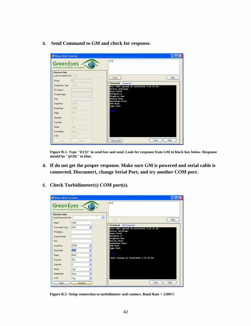
3. Send Command to GM and check for response.
Figure B.3- Type "I{13}" in send box and send. Look for response from GM in black box below. Response
should be "@OK" in blue.
4. If do not get the proper response. Make sure GM is powered and serial cable is
connected. Disconnect, change Serial Port, and try another COM port.
5. Check Turbidimeter(s) COM port(s).
Figure B.5- Setup connection to turbidimeter and connect. Baud Rate = 1200!!!

43
6. Test Turbidimeter connection. Make sure turbidimeter is on and displaying value
and null modem cable is connected. Connect to turbidimeter using ComScript
Terminal Emulator. In send box type “VAL{13}” and send. Should get response
from turbidimeter “VAL = #### NTU”. If you do not try a different serial port!
7. If serial port assignments are not in agreement with profile then “device”
commands in profile need to be changed to correct serial port assignment for
each device otherwise profile will fail.

44