u. s. army weapon systems human-computer interface style guide
TRANSCRIPT

U. S. Army Weapon SystemsHuman-Computer Interface Style Guide
Version 3
December 1999


U.S. Army Weapon SystemsHuman-Computer Interface (WSHCI)Style Guide
Larry W. AveryThomas F. SanquistPeter A. O’MaraAnthony P. ShepardDaniel T. Donohoo
Version 3December 1999
Prepared by
The Pacific Northwest National LaboratoryRichland, WA
Prepared for
Department of the ArmyOffice of the Director of Information Systems forCommand, Control, Communications, and Computers

DISCLAIMER
This report was prepared as an account of work sponsored by an agency ofthe United States Government. Neither the United States Government norany agency thereof, nor Battelle Memorial Institute, nor any of theiremployees, makes any warranty, express or implied, or assumes anylegal liability or responsibility for the accuracy, completeness, orusefulness of any information, apparatus, product, or processdisclosed, or represents that its use would not infringe privately ownedrights. Reference herein to any specific commercial product, process, orservice by trade name, trademark, manufacturer, or otherwise does notnecessarily constitute or imply its endorsement, recommendation, orfavoring by the United States Government or any agency thereof, orBattelle Memorial Institute. The views and opinions of authors expressedherein do not necessarily state or reflect those of the United StatesGovernment or any agency thereof.
PACIFIC NORTHWEST NATIONALLABORATORY
operated byBATTELLE
for theUNITED STATES DEPARTMENT OF ENERGY
under Contract DE-AC06-76RLO 1830

WSHCI Style Guide, Version 3, Foreword
12/31/99 iii
FOREWORD
A stated goal of the U.S. Army has been the standardization of the human computer interfaces(HCIs) of its systems. Some of the tools being used to accomplish this standardization areHCI design guidelines and style guides. Currently, the Army is employing a number of HCIdesign guidance documents. These include the Department of Defense (DoD) HCI StyleGuide, and the User Interface Specifications for the Defense Information Infrastructure (DII).While these style guides provide good guidance for the command, control, communications,computers, and intelligence (C4I) domain, they do not necessarily represent the more uniquerequirements of the Army’s real time and near-real time (RT/NRT) weapon systems. TheOffice of the Director of Information for Command, Control, Communications, andComputers (DISC4), in conjunction with the Weapon Systems Technical ArchitectureWorking Group (WSTAWG), recognized this need as part of their activities to revise theArmy Technical Architecture (ATA), now termed the Joint Technical Architecture - Army(JTA-A). To address this need, DISC4 tasked the Pacific Northwest National Laboratory(PNNL)1 to develop an Army weapon systems unique HCI style guide, which resulted in theWeapon Systems Human-Computer Interface (WSHCI) Style Guide Version 1. Based onfeedback from the user community, DISC4 further tasked PNNL to revise Version 1 andpublish Version 2. In 1999, DISC4 again tasked PNNL to revise the WSHCI and publishVersion 3. This document provides that revision.
The purpose of this document is to provide HCI design guidance for the RT/NRT domainacross the weapon system subdomains of ground vehicle systems, aviation systems, missilesystems, soldier systems, and munition systems. Each subdomain should customize andextend this guidance by developing their domain-specific style guides, which will be used toguide the development of future systems within their subdomains.
This document was developed through a comprehensive review of the open literature anddomain system documentation. In addition, iterative reviews and input from a speciallyorganized working group composed of representatives from each of the Army weapon systemsubdomains were used to tailor the contents to their requirements. This document is meant tobe a living document that will be updated at intervals based on new research and the emergingmaturity of the subdomain style guides.
1 Pacific Northwest National Laboratory is operated for the U.S. Department of Energy by
Battelle under Contract DE-AC06-76RLO 1830.

WSHCI Style Guide, Version 3, Foreword
iv 12/31/99
Copies of this document can be obtained from DISC4 at the following address:
Office of the Director of Information Systems for Command, Control,Communications, and ComputersAttn: SAIS-ADM (Mr. Don Routten)PentagonWashington, DC 20310(703) 614-0514
Copies can also be downloaded from the following Websites:
http://arch-disc4.army.mil/hci/html/hci.htm
http://www.pnl.gov/wshciweb
The authors would like to thank all the people who participated in the development of thisdocument. The WSHCI Style Guide was developed through the combined efforts of thefollowing organizations:
• DISC4
• PNNL
• WSTAWG
• The Weapon Systems HCI Style Guide Working Group
• Monterey Technologies, Incorporated.
The Working Group was particularly critical to the success of this effort through theirvaluable insights into the requirements of each subdomain as well as their extraordinaryefforts to review and comment on drafts of the document. The authors would also like tothank those many organizations and people who provided documents for inclusion in theliterature review.

WSHCI Style Guide, Version 3, Foreword
12/31/99 v
Points of contact for each of the Army weapon system subdomains are as follows:
Ground Vehicles PM Ground Systems IntegrationSFAE-GCSS-W-GSIWarren, MI 48397-5000810-574-6720 or DSN 786-6720
Soldier Systems PM SoldierSSCPM-LW10401 Totten RoadSuite 21Fort Belvoir, VA 22060703-704-3858 or DSN 654-3858
Aviation CMDR, USA AMCOMATTN: AMSAM-AR-ESCBldg 5681Redstone Arsenal, AL 35898-5000205-313-4858
Missile PEO-Missile DefenseSFAE-AMD-TSD-EAP.O. Box 1500Huntsville, AL 35807-3801205-955-1062
Munition DSADirector of Aircraft, Armament, andSmall ArmsAMSTA-LC-CSRock Island, IL 61299-6000301-782-0677
APEOGround Combat and SupportSystemsSFAE-GCSS-PMPicatinny Arsenal, NJ 07806-5000973-724-7115

WSHCI Style Guide, Version 3, Foreword
vi 12/31/99
This page intentionally left blank.

WSHCI Style Guide, Version 3, Contents
12/31/99 vii
CONTENTS
FOREWORD................................................................................................................................ iii
CONTENTS ................................................................................................................................ vii
1.0 INTRODUCTION............................................................................................................. 1-1
1.1 Background .............................................................................................................. 1-1
1.2 Objective .................................................................................................................. 1-3
1.3 Use of This Document.............................................................................................. 1-31.3.1 User-Centered Design ................................................................................. 1-31.3.2 Application to Weapon Systems Development .......................................... 1-51.3.3 Style Guides ................................................................................................ 1-51.3.4 Use of the WSHCI Style Guide .................................................................. 1-6
1.4 Organization............................................................................................................. 1-8
2.0 REAL TIME AND NEAR-REAL TIME SYSTEMS....................................................... 2-12.1 Definitions................................................................................................................ 2-1
2.2 Real Time And Near-Real Time System Characterization ...................................... 2-2
2.3 System Operational Environments........................................................................... 2-2
3.0 GENERAL GUIDELINES................................................................................................ 3-1
3.1 Appropriate Use of Computers ................................................................................ 3-1
3.2 RT/NRT Design Goals ............................................................................................. 3-1
3.3 Design for Crew Tasks............................................................................................. 3-33.3.1 Design for Simultaneous Complex Task Performance ............................... 3-33.3.2 Design for Shared and Redundant Functionality ........................................ 3-3
3.4 Design to Human Limitations .................................................................................. 3-3
3.5 Mission-Critical Functions....................................................................................... 3-33.5.1 Access to Mission-Critical Functions ......................................................... 3-33.5.2 Mission-Critical Function Execution.......................................................... 3-43.5.3 Redundant Methods for Execution of Mission-Critical Functions ............. 3-4
3.6 Retaining Control ..................................................................................................... 3-4
3.7 Controls and Displays .............................................................................................. 3-43.7.1 Control Input Data Feedback ...................................................................... 3-43.7.2 Control and Display Compatibility with Operator Skill Levels ................. 3-4
WSHCI Style Guide, Version 3, Contents
viii 12/31/99
3.7.3 Control and Display Relationships ..............................................................3-53.7.4 Multifunction Displays ................................................................................3-63.7.5 Design for Left and Right Dominance.........................................................3-8
3.8 Design For Multiple Crewstations ............................................................................3-8
3.9 System Setup Prior To Mission Start........................................................................3-8
3.10 Use Of Mnemonics ...................................................................................................3-9
3.11 Display Response Times...........................................................................................3-9
3.12 Messaging .................................................................................................................3-93.12.1 Message Queue............................................................................................3-93.12.2 Automatic Verification of Message Format and Content............................3-93.12.3 Message Received Alert ............................................................................3-103.12.4 Message Management ...............................................................................3-10
3.13 Decision Support System Design............................................................................3-10
3.14 Design For Emergency Shutdown And Recovery..................................................3-10
3.15 Error Tolerance .......................................................................................................3-103.15.1 Identification of Errors ..............................................................................3-113.15.2 Assisting Error Detection ..........................................................................3-113.15.3 Error Recovery...........................................................................................3-11
4.0 GENERAL GUIDELINES FOR INPUT DEVICES.........................................................4-1
4.1 General Design Considerations.................................................................................4-14.1.1 Input Device for Operation on the Move.....................................................4-14.1.2 Dual Input Device Capability ......................................................................4-34.1.3 Use of Joysticks in RT/NRT Systems .........................................................4-34.1.4 Control Sensitivity.......................................................................................4-34.1.5 Cursor Control .............................................................................................4-34.1.6 Direct Manipulation Keypads and Keyboards.............................................4-44.1.7 Appropriate Hand Access to Controls .........................................................4-4
4.2 Function Key Design ................................................................................................4-44.2.1 General.........................................................................................................4-54.2.2 Fixed Function Keys....................................................................................4-64.2.3 Multifunction (Programmable) Keys...........................................................4-74.2.4 Soft Keys .....................................................................................................4-7
5.0 GENERAL GUIDELINES FOR DISPLAYS ...................................................................5-1
5.1 General......................................................................................................................5-15.1.1 General Display Design for RT/NRT Systems............................................5-1

WSHCI Style Guide, Version 3, Contents
12/31/99 ix
5.1.2 Information Proximity Compatibility ......................................................... 5-15.1.3 Stimulus/Central Processing/Response Compatibility................................ 5-25.1.4 Cues for Detecting Changes in Vehicle Attitude ........................................ 5-25.1.5 Alerting Display.......................................................................................... 5-25.1.6 Selection of Alerting Methods .................................................................... 5-35.1.7 Character Size ............................................................................................. 5-35.1.8 Font Style for Legibility.............................................................................. 5-45.1.9 Integration of Display Design ..................................................................... 5-4
5.2 Display Lighting....................................................................................................... 5-45.2.1 Display Luminance and Contrast................................................................ 5-55.2.2 Display Brightness Adjustability ................................................................ 5-75.2.3 Brightness of Illuminated Indicators........................................................... 5-75.2.4 Luminance Compatibility with Ambient Illumination................................ 5-7
5.3 Impact of Vibration on Readability.......................................................................... 5-8
6.0 TOUCH SCREEN DESIGN ............................................................................................. 6-1
6.1 General Guidelines................................................................................................... 6-16.1.1 Touch Screen Use ....................................................................................... 6-16.1.2 Touch Screen Use Limitations.................................................................... 6-16.1.3 Operational Environment and Touch Screens ............................................ 6-26.1.4 Touch Screen Application Development .................................................... 6-26.1.5 Inadvertent Activation Protection ............................................................... 6-26.1.6 Touch Screen Control Object Interaction ................................................... 6-26.1.7 Hardwiring of Critical Safety Controls....................................................... 6-36.1.8 Touch Screens and Autocompletion Capability.......................................... 6-36.1.9 Touch Force Required for Piezoelectric and Resistance Touch Screens.... 6-36.1.10 Window Input Focus with Touch Screens .................................................. 6-4
6.2 Control Object Design.............................................................................................. 6-46.2.1 Control Object Size..................................................................................... 6-46.2.2 Control Object Separation........................................................................... 6-6
6.3 Touch Screen Keyboards ......................................................................................... 6-66.3.1 Numeric Data Entry Keyboard for Touch Screens ..................................... 6-66.3.2 Alphanumeric Data Entry Keyboard for Touch Screens ............................ 6-6
7.0 HELMET-MOUNTED DISPLAYS ................................................................................. 7-1
7.1 General ..................................................................................................................... 7-17.1.1 HMD Design for Situational Assessment ................................................... 7-17.1.2 Use of Opaque Monocular HMDs .............................................................. 7-17.1.3 Design of Attitude Information Display for HMDs.................................... 7-17.1.4 Multi-Image HMD Design.......................................................................... 7-2

WSHCI Style Guide, Version 3, Contents
x 12/31/99
7.1.5 Potential Interference Sources for HMD Tracking Systems .......................7-27.1.6 Image Processors for Infrared (IR)/Low Light Television (LLTV) Image
Fusion ..........................................................................................................7-37.1.7 HMD Movement..........................................................................................7-37.1.8 Potential Reduced Situational Awareness ...................................................7-37.1.9 Minimization of Occlusion of Environmental Sensing ...............................7-37.1.10 Minimization of Cognitive Load .................................................................7-47.1.11 Use of Cueing for Situational Awareness Enhancement.............................7-4
7.2 Binocular HMD Design ............................................................................................7-47.2.1 Use of Binocular HMD Design ...................................................................7-47.2.2 Partial Binocular-Overlap Imagery..............................................................7-47.2.3 Adjustability ................................................................................................7-57.2.4 Binocular HMD for Combined Day and Night Usage ................................7-67.2.5 Design for Maximum Binocular Visual Capabilities ..................................7-67.2.6 Display of Symbology to Both Eyes ...........................................................7-67.2.7 Bi-Ocular Versus Binocular HMD Use.......................................................7-6
7.3 Monocular HMD Design ..........................................................................................7-67.3.1 Use of Monocular HMDs ............................................................................7-67.3.2 Monocular HMD Use for Night Operations................................................7-6
7.4 HMD Optics Design .................................................................................................7-77.4.1 Optic Coatings .............................................................................................7-77.4.2 Adjustment of HMD Optics.........................................................................7-77.4.3 HMD Optics Transmissivity........................................................................7-7
7.5 Field of View ............................................................................................................7-77.5.1 Field of View Size .......................................................................................7-87.5.2 Devices to HMDs ........................................................................................7-87.5.3 Location of Display Symbology in the FOV...............................................7-87.5.4 Resolution....................................................................................................7-87.5.5 Image Brightness .........................................................................................7-97.5.6 Shades of Gray.............................................................................................7-9
7.6 Physical Design of HMDs ........................................................................................7-97.6.1 General.........................................................................................................7-97.6.2 Weight..........................................................................................................7-97.6.3 HMD Weight Distribution.........................................................................7-107.6.4 HMD Visor and Optical Configuration Design.........................................7-107.6.5 HMD Design for Safety.............................................................................7-117.6.6 Minimization of Soldier Distraction..........................................................7-117.6.7 Design for Dismounted Operations ...........................................................7-117.6.8 Helmet Movement Impact on Optics.........................................................7-12

WSHCI Style Guide, Version 3, Contents
12/31/99 xi
7.7 Vibration and HMDs.............................................................................................. 7-127.7.1 Design for Vibrating Environments.......................................................... 7-127.7.2 Attenuation of Head Motion ..................................................................... 7-127.7.3 Adaptive Filtering ..................................................................................... 7-12
8.0 HEAD-UP DISPLAYS ..................................................................................................... 8-1
8.1 General ..................................................................................................................... 8-18.1.1 HUD Advantages over Head-Down Display (HDD).................................. 8-18.1.2 Minimization of Presented Information...................................................... 8-18.1.3 Use of Multiple Cues .................................................................................. 8-28.1.4 Perceptual Segregation of Near and Far Domain Cues............................... 8-28.1.5 Depth Cues.................................................................................................. 8-28.1.6 3-D Cues ..................................................................................................... 8-28.1.7 Compatibility with HDD............................................................................. 8-28.1.8 Nonreflectivity of HUDs............................................................................. 8-28.1.9 Placement of HUDs .................................................................................... 8-38.1.10 Information Projection with HUD Systems................................................ 8-3
8.2 Symbology for HUDs............................................................................................... 8-38.2.1 Use of HDD Symbology............................................................................. 8-38.2.2 Information Origin Certainty ...................................................................... 8-38.2.3 Overuse of Non-Conformal Symbology..................................................... 8-38.2.4 Declutter Capability .................................................................................... 8-3
8.3 Use of Color in HUDs.............................................................................................. 8-48.3.1 Color and HUD Coatings............................................................................ 8-48.3.2 Color Control and HUD Background ......................................................... 8-4
8.4 Field of View............................................................................................................ 8-4
8.5 Raster Image Design ................................................................................................ 8-48.5.1 Visual Raster Image Contrast and Refresh ................................................. 8-48.5.2 HUD Raster Image Luminance................................................................... 8-5
8.6 Dynamic Response................................................................................................... 8-58.6.1 Flicker ......................................................................................................... 8-58.6.2 Jitter............................................................................................................. 8-5
8.7 HUD and FLIR Images ............................................................................................ 8-58.7.1 FLIR and Night Vision Goggles ................................................................. 8-58.7.2 FLIR and HUD Symbology ........................................................................ 8-5
9.0 AUDITORY HUMAN-COMPUTER INTERACTION................................................... 9-1
9.1 General ..................................................................................................................... 9-19.1.1 Limits to the Number of Auditory Signals.................................................. 9-1

WSHCI Style Guide, Version 3, Contents
xii 12/31/99
9.1.2 Selection of Auditory Displays....................................................................9-19.1.3 Operator Request for Repeat of Signal........................................................9-39.1.4 Redundant Cues for Auditory Signals .........................................................9-39.1.5 Redundant Cues for Visual Signals .............................................................9-39.1.6 Timing of Tones and Voice Signals ............................................................9-39.1.7 Lack of Data Transmission Interference......................................................9-39.1.8 Speech Intelligibility....................................................................................9-39.1.9 Avoiding Masking of Auditory Signals.......................................................9-49.1.10 Use of Auditory Interfaces...........................................................................9-59.1.11 Active Noise Reduction...............................................................................9-59.1.12 Use of a Common Lexicon ..........................................................................9-5
9.2 Nonverbal Signals.....................................................................................................9-59.2.1 Use of Nonverbal Auditory Signals.............................................................9-59.2.2 Control of Auditory Signal ..........................................................................9-69.2.3 Auditory Signals - Tonal Display Design....................................................9-69.2.4 Selection of Tonal Frequencies for Background Noise...............................9-79.2.5 Signal Modulation .......................................................................................9-79.2.6 Temporal Form and Shape of Auditory Displays........................................9-7
9.3 Speech Output...........................................................................................................9-89.3.1 When to Use Speech Output........................................................................9-89.3.2 Synchronization of Speech and Visual Warnings .......................................9-89.3.3 Vowel Versus Consonant Sounds in High Noise Environments.................9-89.3.4 Polysyllabic Versus Monosyllabic Words...................................................9-89.3.5 Speech Output in Alarm Handling ..............................................................9-8
9.4 3-D Auditory Localization........................................................................................9-99.4.1 Use of 3-D Auditory Localization ...............................................................9-99.4.2 3-D Auditory Localization and Stimulus-Response Compatibility.............9-9
9.5 Speech Recognition ..................................................................................................9-99.5.1 General Design Considerations for Speech Recognition...........................9-109.5.2 Use of Automatic Speech Recognition Systems .......................................9-129.5.3 Speech Recognition Interaction with Other Primary Tasks ......................9-129.5.4 Environmental Impact on Speech Recognition .........................................9-129.5.5 Whispered Speech .....................................................................................9-129.5.6 Fail-Safe Protocols.....................................................................................9-129.5.7 Redundant or Alternate Means for Input ...................................................9-139.5.8 Interference and Speech Recognition ........................................................9-139.5.9 Push-to-Talk Control .................................................................................9-139.5.10 Location of Microphones...........................................................................9-139.5.11 Training ASR Users...................................................................................9-139.5.12 Dialog Design for Speech Recognition Systems .......................................9-14

WSHCI Style Guide, Version 3, Contents
12/31/99 xiii
9.6 Auditory Icons and Earcons ................................................................................... 9-169.6.1 General ...................................................................................................... 9-169.6.2 Auditory Icons........................................................................................... 9-179.6.3 Earcons...................................................................................................... 9-18
9.7 Sonification and Data ............................................................................................. 9-199.7.1 Advantages to Using Sonification............................................................. 9-209.7.2 Limitations to Data and Sound Mapping .................................................. 9-209.7.3 Use of Sonification.................................................................................... 9-20
10.0 INTERACTIVE CONTROL........................................................................................... 10-1
10.1 General ................................................................................................................... 10-110.1.1 Minimizing Data Entry ............................................................................. 10-110.1.2 Use of Default Values ............................................................................... 10-210.1.3 Early Indication for Visual Detection ....................................................... 10-210.1.4 Operator Control of Processes .................................................................. 10-210.1.5 Operator Selection of Displayed Information........................................... 10-210.1.6 Design for Information Security ............................................................... 10-210.1.7 Dedicated Return to Previous or Top Level.............................................. 10-310.1.8 Multiple Page Displays ............................................................................. 10-310.1.9 Prompt to Save Changes ........................................................................... 10-410.1.10 Hybrid Graphical User Interfaces (GUIs)................................................. 10-4
10.2 Transaction Selection ............................................................................................. 10-410.2.1 Limited Hierarchical Levels...................................................................... 10-410.2.2 Consistent Display and Control Formats Within Levels .......................... 10-410.2.3 Control of Information Update Rates........................................................ 10-410.2.4 Tailoring Information Flow and Control Actions ..................................... 10-510.2.5 Display of Control Options ....................................................................... 10-510.2.6 Availability of Necessary Information...................................................... 10-5
10.3 Error Management and Feedback .......................................................................... 10-510.3.1 Error Management .................................................................................... 10-510.3.2 Feedback ................................................................................................... 10-6
10.4 Cursor ..................................................................................................................... 10-810.4.1 General ...................................................................................................... 10-810.4.2 Redundant Methods for Cursor Movement ............................................ 10-1010.4.3 Targeting Reticle..................................................................................... 10-1010.4.4 Cursor Location....................................................................................... 10-11
10.5 Direct Manipulation ............................................................................................. 10-1110.5.1 Object Design.......................................................................................... 10-1210.5.2 Option Selection...................................................................................... 10-1310.5.3 Click and Point Versus Click and Drag .................................................. 10-14

WSHCI Style Guide, Version 3, Contents
xiv 12/31/99
10.6 Menu Design.........................................................................................................10-1410.6.1 Format of Menus......................................................................................10-1410.6.2 Return to the Top or Next Level..............................................................10-1610.6.3 Visual Distinction Between Selected and Non-Selected Options ...........10-1610.6.4 Menu Navigation .....................................................................................10-16
11.0 SCREEN DESIGN...........................................................................................................11-1
11.1 General....................................................................................................................11-111.1.1 Grouping by Proximity or Other Cues.......................................................11-211.1.2 Presentation of Alerting Information.........................................................11-211.1.3 Key Features Protection.............................................................................11-211.1.4 Location of Most Important Information...................................................11-311.1.5 Status Message Area..................................................................................11-311.1.6 Weapon and Sensor Systems Orientation..................................................11-311.1.7 Multipage Information Display .................................................................11-411.1.8 Consistent Appearance for Similar Controls and Screen Elements...........11-411.1.9 Screen Elements Identification by Appearance.........................................11-411.1.10 Fire Control Information Location ............................................................11-511.1.11 Separation of Screen Elements for Focused Attention ..............................11-511.1.12 Perspective Displays..................................................................................11-5
11.2 Window Design ......................................................................................................11-511.2.1 Fixed Window Design ...............................................................................11-611.2.2 Window Appearance .................................................................................11-611.2.3 Multifunction Key Context Definition ......................................................11-611.2.4 Window Control ........................................................................................11-611.2.5 Window Dialog..........................................................................................11-811.2.6 Multiple Layers of Windows...................................................................11-1211.2.7 Dialog Box Design ..................................................................................11-12
11.3 Text and Data Presentation ...................................................................................11-1311.3.1 Information Requirements for the Content of Displays ..........................11-1311.3.2 Text/Data Display....................................................................................11-1411.3.3 Text/Data Entry .......................................................................................11-16
11.4 Graphics ................................................................................................................11-1711.4.1 Map Graphics...........................................................................................11-1711.4.2 Presentation Graphics ..............................................................................11-21
12.0 CODING ..........................................................................................................................12-1
12.1 General....................................................................................................................12-112.1.1 Coding of Time-Critical Information ........................................................12-112.1.2 Code Consistency and Meaningfulness .....................................................12-1

WSHCI Style Guide, Version 3, Contents
12/31/99 xv
12.2 Brightness Coding.................................................................................................. 12-112.2.1 Use of Brightness Coding ......................................................................... 12-112.2.2 Levels of Brightness Coding..................................................................... 12-1
12.3 Flash Coding .......................................................................................................... 12-112.3.1 Use of Flash Coding.................................................................................. 12-112.3.2 Flash Rates ................................................................................................ 12-212.3.3 Rate of Flashing ........................................................................................ 12-212.3.4 Acknowledgment of Flash Coding ........................................................... 12-2
12.4 Pattern and location Coding ................................................................................... 12-2
12.5 Color Coding.......................................................................................................... 12-212.5.1 Use of Color Coding ................................................................................. 12-212.5.2 Color Codes for Alerts and Warnings....................................................... 12-312.5.3 Color Codes and Population Stereotypes.................................................. 12-312.5.4 Minimal Use of Color for Quick Response .............................................. 12-412.5.5 Color Code Redundancy ........................................................................... 12-412.5.6 Use of Color Cueing in Display Design.................................................... 12-412.5.7 Label Background Color Changes to Indicate Off-Normal Conditions ... 12-4
12.6 Symbology ............................................................................................................. 12-512.6.1 Use of Symbology..................................................................................... 12-612.6.2 Contribution of Symbology to Primary Display Objectives..................... 12-612.6.3 Symbols as Analogs for Coded Events or Elements................................. 12-612.6.4 RT/NRT Symbology Standards ................................................................ 12-612.6.5 Use of Graphics and Colors with Symbols ............................................... 12-612.6.6 Size Coding............................................................................................... 12-812.6.7 Multiple Coding Variables........................................................................ 12-812.6.8 Symbology Overlaid on Video ................................................................. 12-812.6.9 Improving Symbol Recognition................................................................ 12-912.6.10 Visual Symbol Design Guidelines ............................................................ 12-9
12.7 Icon Design ............................................................................................................ 12-912.7.1 Icon Usage............................................................................................... 12-1012.7.2 Icon Design Principles ............................................................................ 12-1012.7.3 Icon Shape............................................................................................... 12-1112.7.4 Icon Size.................................................................................................. 12-1212.7.5 Icon Color ............................................................................................... 12-1212.7.6 Icon Boundary Lines............................................................................... 12-1312.7.7 Icon Labeling .......................................................................................... 12-1312.7.8 Hot Zone ................................................................................................. 12-13

WSHCI Style Guide, Version 3, Contents
xvi 12/31/99
APPENDIX A - ACRONYMS ..................................................................................................A-1
APPENDIX B - REFERENCES................................................................................................B-1
APPENDIX C - GLOSSARY....................................................................................................C-1
INDEX ........................................................................................................................................ I-1
LIST OF FIGURES
Figure 1.1 User-Centered Design and Style Guide Development Process ...............................1-4
Figure 1.2 Process for Developing a Subdomain-Specific Style Guide from the WSHCI StyleGuide ..................................................................................................................1-7
Figure 3.1 Illustration of the Primary Visual Zone ...................................................................3-7
Figure 3.2 Illustration of Consistent Input and Output Methods Among Crewstations ...........3-8
Figure 4.1 Illustration of a Two-Handed Controller* ...............................................................4-2
Figure 4.2 Illustration of Soft Keys...........................................................................................4-9
Figure 4.3 Example of Graying Out Inactive Keys.................................................................4-10
Figure 5.1 Illustration of How to Calculate Visual Angle ........................................................5-3
Figure 6.1 Illustration of Visual Feedback for Touch Screen Control Objects.........................6-3
Figure 6.2 Touch Screen Control Object Size...........................................................................6-5
Figure 6.3 Illustration of Touch Zone Size ...............................................................................6-5
Figure 7.1 Illustration of Partial Binocular-Overlap .................................................................7-5
Figure 10.1 Illustration of Pointer Shape Used for Visual Feedback of Cursor Function ..10-9
Figure 10.2 Example of Hot Spot........................................................................................10-9
Figure 10.3 Examples of Pushbutton Labels .....................................................................10-12
Figure 10.4 Illustration of How a Menu Option Should be Highlighted...........................10-15

WSHCI Style Guide, Version 3, Contents
12/31/99 xvii
Figure 10.5 Illustration of Visual Indication of Submenu .................................................10-17
Figure 10.6 Illustration of Two Types of Menu Navigation Aids .....................................10-18
Figure 11.1 Illustration of Weapon/Sensor Orientation.......................................................11-3
Figure 11.2 Examples of Visually Identifiable Controls and Screen Elements...................11-4
Figure 11.3 Example of Fire Control Information Placement Relative to the Reticle ........11-5
Figure 11.4 Illustration of Window Location when Opened by a Multifunction Key ........11-7
Figure 11.5 Example of a Single Selection Pop-Up Window .............................................11-9
Figure 11.6 Example of Current or Default Selection on Single Selection Pop-UpWindows...........................................................................................................11-9
Figure 11.7 Example of a Multiple-Selection Pop-Up Window .......................................11-10
Figure 11.8 Illustration of How To Visually Indicate Input Focus....................................11-11
Figure 11.9 Illustration of Editable and Uneditable Text Fields .......................................11-14
Figure 11.10 Illustration of How Data Should Be Justified ................................................11-15
Figure 11.11 Example of How to Present Likelihood of Outcome Data.............................11-16
Figure 11.12 Illustration of Querying Symbols on a Map Display......................................11-19
Figure 12.1 Illustration of Enhanced Size of Critical Symbol Feature for Recognition......12-9
Figure 12.2 Example of a Single Icon Set .........................................................................12-11
Figure 12.3 Example of Mirrored Icons ............................................................................12-12
Figure 12.4 Example of Hot Zone .....................................................................................12-14

WSHCI Style Guide, Version 3, Contents
xviii 12/31/99
LIST OF TABLES
Table 1.1 Example of Levels of Specificity Between Handbooks, Domain Style Guides,and User-Interface Specifications ......................................................................1-6
Table 5.1 Characteristics of Alphanumeric Characters Contributing to Legibility ...........5-4
Table 5.2 Recommended Display Contrast Levels for RT/NRT Systems.........................5-6
Table 6.1 Recommended Resistance for Touch Screen Control Activation......................6-4
Table 9.1 Guidance for Selection of Audio Signals Based on Function............................9-2
Table 9.2 Intelligibility Criteria for Voice Communications Systems...............................9-4
Table 12.1 Color Code Meanings ......................................................................................12-3
Table 12.2 Color Coding for Night Vision Imaging Systems (NVIS)...............................12-3

WSHCI Style Guide, Version 3, Introduction
12/31/99 1-1
1.0 INTRODUCTION
1.1 BACKGROUND
The U.S. Army has long recognized the importance of the human in overall systemeffectiveness through its emphasis on human factors engineering (HFE) in system design andevaluation. As the complexity of systems entering the Army inventory has increased, so hasthe complexity of the interface between the operator and the machine. This has led to anincreased potential for work overload on the operator, increased chances for human error, anda corresponding potential decrease in overall system effectiveness. This is particularly truewhere the system relies on computers. Effective design of the human-computer interface(HCI) has become critical to system success.
Designing an effective HCI focuses on achieving three major goals:
• Design an HCI that meets the user’s operational needs.
• Ensure that the HCI has been designed to maximize human and system performanceand to minimize human error.
• Standardize HCI design.
Some of the tools to achieve these goals include design guidelines documents, standards, andstyle guides. The U.S. Department of Defense (DoD) has published a number of guidelinesdocuments and style guides that address the design of the HCI for military systems. Thesedocuments include, but are not limited to, the following:
• DoD HCI Style Guide (U.S. DoD 1995)
• User Interface Specification for the Defense Information Infrastructure (DII) (U.S.DoD 1999a)
• Human Factors Design Guidelines for the U.S. Army Tactical Command and ControlSystem (ATCCS) Soldier-Machine Interface (U.S. Army 1992).
These documents provide human factors design guidance, starting from the DoD HCI StyleGuide, which contains general, high-level design guidelines, down through successive levelsof tailoring and specificity. Each of these documents, while being comprehensive, is moreappropriate to command, control, communications, computers, and intelligence (C4I) systemsthat use extensive windowing, are deployed in buildings, ships, shelters and tents, and do notrequire almost instantaneous decision-making. What these documents do not address well are

WSHCI Style Guide, Version 3, Introduction
1-2 12/31/99
the unique requirements of real time and near-real time (RT/NRT) systems, such as theweapon systems domain, and particularly RT/NRT systems from the following subdomains:
• Aviation Systems - This subdomain is responsible for developing aircraft systems tosupport a variety of military missions, including attack, reconnaissance/security, utility,cargo and special operations. These missions encompass various environmental factorsthat can impact aircrew performance and HCI design, with the task environmentcharacterized as being: information-intensive, dynamic, time-constrained, andimposing severe consequences for error. High vibration, ambient noise, restrictedvisibility, and limited cockpit real estate for controls and displays are additional factorsto be considered with aviation systems.
• Ground Vehicle Systems - This subdomain is composed of the following elements:tanks, infantry fighting vehicles, engineering vehicles with processor-based missioncontrols/sensors, howitzers, mortar systems, and chemical/biological systems withprocessor-based mission controls/sensors.
• Missile Systems - This subdomain encompasses rocket and missile systems used indiverse Battlefield Functional Areas including Air and Missile Defense, Fire Support,Close Combat, and Special Operations. The diversity of missions that rocket andmissile systems must perform induces a variety of system solutions including shoulder-fired missiles, line-of-sight direct fire missiles and rockets, non-line-of-sight indirectfire missiles and rockets, and air and missile defense systems. Broadly, missile systemsmay be described by subsystem elements as consisting of: 1) missile, 2) launcher, 3)C3I (including fire control or battle management), and 4) sensor.
• Soldier Systems - This subdomain is responsible for developing integrated soldiersystems. These soldier systems integrate target location, target identification, targetacquisition, enhanced survivability, navigation, position location, enhanced mobilityand command and control into a system worn or carried by a soldier in performance oftheir duties.
• Munition Systems – This subdomain encompasses non-mobile, transportable, weaponsystems which include, but are not limited to, munitions and munitions integrated withcombat sensors, control stations, and the supporting combat communication systemswith their repeaters and gateways. The Munitions Systems subdomain includes anysystem or subsystem containing an explosive warhead (such as dumb, smart, andprecision bombs, or mines and artillery shells) or non-lethal deterrent and that detects,classifies, identifies, intercepts, and destroys or negates the effectiveness of the enemy.
The following style guide has been developed to provide guidance more appropriate toRT/NRT systems and the weapon systems domain.

WSHCI Style Guide, Version 3, Introduction
12/31/99 1-3
1.2 OBJECTIVE
The objective of this style guide, the Weapon Systems Human Computer Interface (WSHCI)Style Guide, is to provide design guidelines that can be used to design the HCI for RT/NRTsystems. These guidelines are meant to:
• Provide HCI design guidance–focusing in look and behavior–that will assist indesigning weapon systems to optimize human-system effectiveness and reduce humanworkload and error.
• Complement and extend those guidelines contained in the DoD HCI Style Guide (U.S.DoD 1995).
• Address guidelines that are applicable across most or all of the RT/NRT subdomains.
• Provide a starting point for developing subdomain-specific style guides that will furtherthe goal of standardization.
These guidelines are intended to be a living document. The guidelines will be revised,depending on the emergence of more focused subdomain HCI style guides as well as futureresearch.
1.3 USE OF THIS DOCUMENT
Effective system design for the user can only be accomplished if HFE is involved early in thedesign process. There is a well-established and documented set of processes andmethodologies for applying HFE in the design process, for example in MIL-HDBK-46855,Human Engineering Requirements for Military Systems, Equipment, and Facilities (U.S. DoD1996b). These processes and methodologies will not be repeated in this document. Mostgermane to this document are the processes of user-centered design and style guide tailoring.
1.3.1 User-Centered Design
User-centered design is an approach for design that focuses on improving system usabilitythrough iterative design and significant user involvement. Figure 1.1 provides an illustrationof the user-centered design process.

WSHCI Style Guide, Version 3, Introduction
1-4 12/31/99
OperationalRequirement
Define User Tasks
Lessons Learned
DevelopUnderstanding of
the User
Define User/System
PerformanceRequirements
Develop UserScenarios
Design andPrototype
User Evaluation
Implementation
Testing
Revision of StyleGuide
DomainUnique DesignRequirements
CommercialGUI Style
Guide
Domain StyleGuide
System/ApplicationStyle Guide
System/Application
Unique DesignRequirements
System/Application UISpecification
StandardsHandbooksEtc.Interaction with
Users
Figure 1.1 User-Centered Design and Style Guide Development Process

WSHCI Style Guide, Version 3, Introduction
12/31/99 1-5
The four key principles of user-centered design are (adapted from Gould 1988):
• Early and continual focus on users. Focus on the users from the beginning. Followthis by continually contacting users to understand their requirements and capabilities.
• Integrated design. Develop all aspects of design that address usability in parallel andunder one focus. Integrate usability design with overall system design.
• Early and continual user testing. Involve the user from the beginning andcontinuously. This early involvement is key in evaluating the design concepts andemerging prototypes.
• Iterative design. Modify the system/application design iteratively based on the resultsof user testing.
1.3.2 Application to Weapon Systems Development
The application of user centered design to the development of weapon systems may varysomewhat depending on the type of acquisition strategy being pursued, but the basic premiseis consistent with the process outlined in Figure 1.1. Users, as well as qualified human factorsand usability specialists, need to be involved in the full acquisition process, from requirementsdevelopment through post-fielding lessons learned data collection. Currently, there are fewDOD documents that define how the user-centered design process should be applied toweapon system development. MIL-HDBK-46855 (DoD 1996b) and MIL-HDBK-763 (DoD1987) provide some guidance on human factors design processes and procedures, but do notnecessarily reflect the current DoD acquisition environment. Although it is currently beyondthe scope of this document to provide user-centered design processes for weapon systemdevelopment, user interface designs should be based on operator tasks to ensure optimumsystem performance (Armstrong and Steinberg, 1998).
1.3.3 Style Guides
A key part of user-centered design for the HCI is the development of style guides. An HCIstyle guide is a document that specifies design rules and guidelines for the look and behaviorof the user interaction with a software application or a family of software applications. Thegoal of a style guide is to improve human performance and reduce training requirements byensuring consistent and usable design of the HCI across software modules, applications, andsystems. The style guide represents "what" user interfaces should do in terms of appearanceand behavior, and can be used to derive HCI design specifications that define "how" the rulesare implemented in the HCI application code.

WSHCI Style Guide, Version 3, Introduction
1-6 12/31/99
A style guide differs from a handbook or a user interface specification. Handbooks aretypically documents that provide broad design guidance, including both design guidelines anddesign methodology. Style guides tailor the guidance contained in a handbook to providemore specificity for the design of an application, system, or family of systems. A userinterface specification further tailors the guidance contained in a style guide and providesspecific design rules for an application or system. Figure 1.1 provides an illustration of thistailoring process as part of user-centered design. Table 1.1 provides an illustration of thevarying levels of specificity for design guidance contained in these various documents.
Table 1.1 Example of Levels of Specificity Between Handbooks, Domain StyleGuides, and User-Interface Specifications
Document Type Example Guidance Statement
Style Guide/Handbook Format the display of hierarchical menus, dialog boxes, and pop-upwindows such that options that actually accomplish control entriescan be distinguished from those that merely branch to other menuframes.
Domain Style Guide Provide a visual indication when a menu option will take theoperator to a submenu. For example, use an arrowhead to indicate acascading menu or three ellipses to indicate a pop-up menu.
User-InterfaceSpecification
Menu options that lead to a cascading menu shall be indicated by anarrow placed to the right of the option label on the multifunction orsoft key.
1.3.4 Use of the WSHCI Style Guide
The WSHCI Style Guide is, in reality, a set of design guidelines, not a style guide as defined inparagraph 1.3.2. The WSHCI Style Guide should be used as a starting point for developingsubdomain- and system-specific style guides. The relevant guidance from the WSHCI StyleGuide should be expanded with subdomain-specific requirements and tailored to meet therequirements of the subdomain. Figure 1.2 illustrates this process. Subdomain style guideswill become annexes to the WSHCI Style Guide as they are completed and approved.

WSHCI Style Guide, Version 3, Introduction
12/31/99 1-7
Review by DomainPersonnel and
Users
SubDomainUnique DesignRequirements
DOD HCIStyle Guide
CommercialGUI Style
Guide
DraftSubDomainStyle Guide
WSHCI
Identification ofRelevant Guidance
SubDomainStyle Guide
Figure 1.2 Process for Developing a Subdomain-Specific Style Guidefrom the WSHCI Style Guide

WSHCI Style Guide, Version 3, Introduction
1-8 12/31/99
1.4 ORGANIZATION
The remainder of the body of this document is organized into the following sections:
• 2.0 - Real Time and Near-Real Time Systems
• 3.0 - General Guidelines
• 4.0 - General Guidelines for Input Devices
• 5.0 - General Guidelines for Displays
• 6.0 - Touch Screen Design
• 7.0 - Helmet-Mounted Displays
• 8.0 - Head-Up Displays
• 9.0 - Auditory Human-Computer Interaction
• 10.0 - Interactive Control
• 11.0 - Screen Design
• 12.0 - Coding
• Appendix A - Acronyms
• Appendix B - References
• Appendix C – Glossary
• Index.

WSHCI Style Guide, Version 3, Real Time and Near-Real Time Systems
12/31/99 2-1
2.0 REAL TIME AND NEAR-REAL TIME SYSTEMS
The objectives of this section are to provide designers with an understanding of real time andnear-real time systems, the environments in which they are employed, and some of the high-level considerations that should be used to guide the design of their HCIs.
2.1 DEFINITIONS
Currently, no definitions for real time (RT) systems and near-real time (NRT) systems areapproved for use by the U.S. Army. Joint Publication 1-02 (U.S. DoD 1994) provides jointlyapproved definitions for the terms “Real Time” and “Near-Real Time” that focus solely onelectromagnetic signal transmission characteristics. However, when these terms are used asmodifiers to describe systems, the resulting definitions are imprecise and ambiguous.
The definition of time, when utilized in the context of RT/NRT systems, can be consideredfrom three viewpoints:
• Time, as a criterion for usability, considers the system response time to user input andthe time required by a user to perform a task.
• Time, as a part of information, considers system data as a function of time in thedecision process, where “stale” data may result in an incorrect decision.
• Time, in relation to timeliness, relates to overall demands on either the system, theuser, or both.
The consensus among users is that RT/NRT systems and C4I systems are different. Thisdifferentiation can be made based on the deterministic nature of RT/NRT systems and theasynchronous nature of C4I systems. The general concurrence is, however, that anothermajor differentiating factor is whether or not a system performs time-critical operationalfunctions. Because no definitions are approved for army-wide use, and because “time-critical” is relative, systems are categorized as either RT/NRT or C4I based on domainperspectives and opinions of users. As a direct result, no clear agreement can be obtainedfrom the user population as to which systems constitute the true RT/NRT system baseline.
To identify appropriate systems to use for “baseline characterization,” the following workingdefinition of RT/NRT systems was used in constructing the WSHCI Style Guide:
“RT/NRT Systems - Systems where little or no delay exists between the time an eventoccurs and the time it is presented to the user; and where there is an operationalrequirement for the user to quickly recognize this presentation, comprehend itssignificance, and determine and execute appropriate action(s).”

WSHCI Style Guide, Version 3, Real Time and Near-Real Time Systems
2-2 12/31/99
While there are subtle technical differences between an RT and an NRT system, based on theabove definition, there is no perceived difference to the user. Therefore, RT and NRTsystems will be treated as one type of system in this document.
2.2 REAL TIME AND NEAR-REAL TIME SYSTEM CHARACTERIZATION
RT/NRT systems may exist in their own right or as components of C4I systems. As a generalrule, RT/NRT systems or components exhibit the following characteristics that furtherdistinguish them from C4I systems:
• Time-Critical Operational Function Orientation. RT/NRT systems or componentsare designed to perform operational functions where time-critical user responses areessential to mission accomplishment. Definitions for “time-critical” vary acrossdomains.
• High-Stress Decision Environment. RT/NRT systems or components are often foundin environments where users must make decisions and take actions when the penaltyfor incorrect or improper responses can be severe, e.g., mid-air collision, failure tointercept an inbound missile, failure to take evasive action, etc. The outcome of anincorrect decision may include serious injury or death for the user or for individuals atother locations. Often these decisions must be made in time competition with otherequally important decisions.
• Situational Awareness. RT/NRT systems or components are generally designed toprovide users with immediate situational awareness of rapidly changing events andoften include position location information (PLI) or related information, i.e., two-dimensional (2-D)/three-dimensional (3-D) location, vector data, relative bearing, etc.,as a major system focus. This information is usually computed by the system orcomponent, based on input received from externally focused sensors.
• Context Sensitivity of Information. A critical aspect of RT/NRT systems is thatinformation displayed must be context-sensitive to the task or mission currently beingperformed to ensure awareness of and focus on the mission in a rapidly changingenvironment.
2.3 SYSTEM OPERATIONAL ENVIRONMENTS
As is the case with C4I systems, RT/NRT systems can potentially exist at all unit echelonsand can be designed for use in a variety of possible environments. In general, emergingRT/NRT systems are being inserted into increasingly hostile operational environments. Theimpact of unfriendly environmental conditions on operator-system interactions can yield

WSHCI Style Guide, Version 3, Real Time and Near-Real Time Systems
12/31/99 2-3
significant overall degradation in operational performance and must be accommodated duringsystem design. Because RT/NRT systems are time-critical by nature, the effects of theoperational environment can be particularly important.
Some of the more significant conditions for consideration in RT/NRT system design are:
• Shock and Vibration. Shock and vibration effects on the operator, such as thoseassociated with moving vehicles (ground and aircraft) and impulse shock due to firingweapons, can make it difficult for operators to comprehend visually presented data andto execute appropriate control actions on displays. Refer to Section 10.4 in theEngineering Data Compendium Human Perception and Performance (Boff andLincoln 1988) for a discussion on the impact of vibration on human performance.Also, operators in these environments may be required to use one hand for stabilityinside the moving platform and, because of this, may only be able to interact withsystem controls with a single hand.
• High-Decibel Noise. High-decibel noise, such as that associated with some aircraft,large vehicles, and the general combat environment, can make it difficult for operatorsto notice audible cues, alerts, and alarms.
• Variable Ambient Lighting. Variable ambient lighting conditions can make itdifficult for operators to quickly focus–and therefore comprehend–visually presenteddata. This is particularly pronounced in environments where the operator is exposed torapidly fluctuating lighting conditions, such as bright sunlight followed by shadow.
• Physically Constrained Work Areas. Physically constrained work areas, such asthose found inside vehicle crew compartments, can make it difficult for operators toobserve system displays and to interact with system controls. In addition, physicallyconstrained areas can impact the size and number of controls and displays.
• Nuclear, Biological, and Chemical (NBC) Environments. Operating a system whilewearing NBC clothing can make it difficult to view displays, hear audible signals,communicate verbally, and operate controls. In addition, sustained operation in NBCenvironments can lead to heat stress and other physiological degradation of operatorperformance.
• Temperature Extremes. Operation in extreme heat or extreme cold can impact bothoperator and system performance. Military personnel, in particular, are susceptible toperformance degradation in temperature-extreme environments and while wearing coldweather clothing.

WSHCI Style Guide, Version 3, Real Time and Near-Real Time Systems
2-4 12/31/99
• Dirt, Dust, and Humidity. Dirty, dusty, and humid environments can impact bothoperator and system performance. These conditions can cause difficulties in reading,in operating equipment, and in reducing reliability of equipment.
• Survivability. Designing a system to survive conditions such as electromagneticinterference (EMI), electromagnetic pulse (EMP), crashworthiness, and ballisticprotection can impact system weights and sizes.
• Open Hatch Operations. Operating systems in an open hatch mode can causeadditional display illumination requirements for visibility and readability, which mustbe accommodated without compromising anti-detection requirements. Additionally,open-hatch operations will create a noisier workspace and may also yield requirementsfor remoted controls and displays.
• Portability. In dismounted operations, systems must be carried by the operator inaddition to their normal load. Weight, comfort, battery life, and compatibility withother equipment are critical design issues
WSHCI Style Guide, Version 3, General Guidelines
12/31/99 3-1
3.0 GENERAL GUIDELINES
The following section provides general guidelines for the design of HCIs for RT/NRT weaponsystems.
3.1 APPROPRIATE USE OF COMPUTERS
Design the computer-enhanced system to increase system effectiveness and reduce operatorworkload by allocating functionality appropriately between the human and the computer.Operators possess certain inherent skills and attributes that make them superior to automationfor certain types of tasks. The following are general types of tasks that are more appropriatefor operators:
• Flexible time-critical decision-making, for example, to engage or not to engage atarget, or in some cases to modify existing automated rules of engagement duringtactical operations
• Complex pattern recognition, for example, determining whether the target is a friend orfoe, or recognizing subtle changes to a dynamic engagement operation
• Decision-making under time-critical and uncertain conditions, for example, decidingwhich is the best sensor and/or weapon to use
• Communications where voice inflection is critical.
Computers are capable of providing information and assistance to the operator for some ofthese tasks but are not the best choice for final responses. For mission-critical tasks that fallwithin these categories, use computers to monitor and signal state changes. However, ensurethat the operator will always make the final input. For non-mission-critical tasks, permit theoperator to determine whether to let the computer make the decision. (Parasuraman 1987;U.S. Army 1995f, 1995g; WSSG Working Group 1996)
3.2 RT/NRT DESIGN GOALS
Consider in the development of RT/NRT systems the following high-level design goals,presented in no order of priority:

WSHCI Style Guide, Version 3, General Guidelines
3-2 12/31/99
a. Minimize requirements for the operator to focus on the internal system environmentand maximize the focus on the external environment or threat.
b. Minimize cursor travel requirements across and between displays or windows on adisplay.
c. Minimize switching visual focus between different displays during a procedure orwindows on a display.
d. Minimize the use of color, except where it enhances performance.
e. Minimize the number of steps within a procedure.
f. Minimize the amount of required display manipulation such as screen adjustment,window sizing, window placement, and window manipulation.
g. Minimize the frequency and significance of operator error.
h. Minimize the requirement for operator memory recall.
i. Maximize the distribution of both physical and cognitive workload for individualoperators and between crew members.
j. Maximize the availability and speed of feedback, and keep the operator informed aboutsystem processing.
k. Maximize the use of error recovery.
l. Maximize the use of similar procedures.
m. Maximize the relevance of human-computer dialogue to the operator's job.
n. Maximize the use of standard and consistent human-computer dialogue.
o. Maximize the use of preset, templated, and automated setup procedures.
p. Minimize the display of information not directly relevant to the immediate decision theoperator must make.
q. Maximize, for crew-served systems, the ability of the crew to directly shareinformation and control functions between crewstations.
r. Minimize the number of times the operator’s hands need to leave vehicle controls.

WSHCI Style Guide, Version 3, General Guidelines
12/31/99 3-3
s. Maximize system safety.
(Obermayer and Campbell 1994; WSSG Working Group 1996, 1997)
3.3 DESIGN FOR CREW TASKS
3.3.1 Design for Simultaneous Complex Task Performance
Design the human-to-system interaction, when complex tasks must be performedsimultaneously, for crew performance rather than for individual performance. This limitssituations where operator performance is degraded because operators must performsimultaneous complex tasks, such as piloting a vehicle while concurrently recognizing andacting on target acquisition data. (Dominessy et al. 1991)
3.3.2 Design for Shared and Redundant Functionality
When crew can share functionality, with the control being exclusive to one crew member,provide the following:
a. A visual indication of who has control.
b. The capability for an override of any lock-out of control functionality, when one crewmember may have to take over control for another injured crew member. Ensure thatthe override is communicated prior to its occurrence to preclude inappropriate override.
(WSSG Working Group 1996)
3.4 DESIGN TO HUMAN LIMITATIONS
Design the user interface for RT/NRT systems such that it does not overload user cognitiveprocessing, perception, decision-making, and manipulation. A design that considers thelimitations in human sensory, perceptual, and cognitive abilities helps avoid over-stressing theoperator. Designing to human limitations is particularly important for decision supportsystems. (U.S. Army 1995g; Heinecke 1993; Walrath 1989)
3.5 MISSION-CRITICAL FUNCTIONS
3.5.1 Access to Mission-Critical Functions
Provide direct access to mission-critical functions to minimize the number of choices duringtime and mission-critical phases of operation. This can be accomplished by separating the

WSHCI Style Guide, Version 3, General Guidelines
3-4 12/31/99
mission-critical functions from the non-mission-critical functions, and designing the HCI sothat mission-critical options are made through dedicated controls, menu options at the top of amenu list, or input focus directed to the critical options. (U.S. Army 1995g)
3.5.2 Mission-Critical Function Execution
Design the HCI so that the number of actions required to initiate a mission-critical function isminimized, while ensuring that inadvertent activation is prevented. (U.S. Army 1995g; SiteVisit to U.S. Army Tank-Automotive Research, Development, and Engineering Center[TARDEC] 1996; WSSG Working Group 1997)
3.5.3 Redundant Methods for Execution of Mission-Critical Functions
Provide the operator with redundant methods to execute mission-critical functions, forexample, a pointing device and a touch screen. One of the redundant methods should be theprimary input method. Ensure that it is obvious to the operator which method is primary andwhich is secondary. (U.S. Army 1995g; Site Visit TARDEC 1996)
3.6 RETAINING CONTROL
Ensure that the operator retains control of the system so that system status, e.g., targetengaged or location, is always known and the operator has final determination of systemactions. (U.S. Army 1995g)
3.7 CONTROLS AND DISPLAYS
3.7.1 Control Input Data Feedback
Design the system so that the operator receives clear, unambiguous, and rapid feedback forcontrol data being entered and that any data displayed do not mislead the operator with regardto nomenclature, units of measure, sequence of task steps, or time phasing. (GeneralDynamics 1986)
3.7.2 Control and Display Compatibility with Operator Skill Levels
Ensure that the design of controls and displays is compatible with the appropriate operatorskill levels as well as tailorable for differing skill levels, e.g., novices versus experiencedusers. (General Dynamics 1986; WSSG Working Group 1996, 1997)

WSHCI Style Guide, Version 3, General Guidelines
12/31/99 3-5
3.7.3 Control and Display Relationships
Ensure that control and display relationships, including control and display objects on ascreen, are straightforward and obvious to the operator and that control actions are simple anddirect. (General Dynamics 1986; WSSG Working Group 1997)
3.7.3.1 Relationship
Ensure that the relationship of a control to its corresponding display or displayedobject is apparent and unambiguous by:
• Location adjacent to associated displays
• Proximity, similarity of groupings, coding, labeling, or similar techniques.
(U.S. DoD 1996a)
3.7.3.2 Functional Grouping
Design functionally related controls and displays so that they are located inproximity to one another, arranged in functional groups. Design controls related to aspecific task so that they are located close to one another to maximize proximitycompatibility. (U.S. DoD 1996a; Wickens and Carswell 1995)
3.7.3.3 Consistency
Ensure that the location of recurring functional groups and individual items isconsistent from panel to panel and, for multifunction displays, from screen to screen.(U.S. DoD 1996a)
3.7.3.4 Simultaneous Use
Ensure that, when the operator must monitor a display concurrently with themanipulation of a related control, the display is located in the primary visual zone.See Figure 3.1. (U.S. DoD 1996a)
3.7.3.5 Minimization of Eye Focus Shifts
Design the operator-system interface to minimize visual shifts between displays andcontrols—as well as displays and displays—that require the eye to refocus. (WSSGWorking Group 1996)

WSHCI Style Guide, Version 3, General Guidelines
3-6 12/31/99
3.7.4 Multifunction Displays
3.7.4.1 Use
Consider providing multifunction displays (MFDs), where appropriate, that allowaccess to the system functionality, rather than dedicated displays. This reduces thenumber of physical controls and displays required where control panel surface islimited. (U.S. Army 1995g)
3.7.4.2 Redundancy
When using MFDs, provide redundancy to ensure that system safety is notcompromised. For example, provide hardwired controls for critical safety functions,or provide the ability to send display input to another display device in the event ofdisplay failure. (WSSG Working Group 1997)
3.7.4.3 Design
Design MFDs in accordance with the relevant guidance contained in Sections 4.0,“General Guidelines for Input Devices,” 5.0, “General Guidelines for Displays,” 6.0,“Touch Screen Design,” 8.0, “Head-Up Displays,” and 9.0, “Auditory Human-Computer Interaction.”
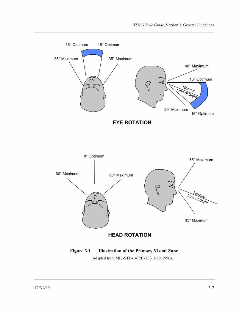
WSHCI Style Guide, Version 3, General Guidelines
12/31/99 3-7
40° Maximum
15° Optimum
20° Maximum15° Optimum
NormalLine of Sight
15° Optimum 15° Optimum
35° Maximum 35° Maximum
0° Optimum
60° Maximum 60° Maximum
EYE ROTATION
HEAD ROTATION
55° Maximum
35° Maximum
NormalLine of Sight
Figure 3.1 Illustration of the Primary Visual Zone Adapted from MIL-STD-1472E (U.S. DoD 1996a)

WSHCI Style Guide, Version 3, General Guidelines
3-8 12/31/99
3.7.5 Design for Left and Right Dominance
Consider, when designing the controls and displays for some types of weapon systems, thatoperators may be either left- or right-handed or eye dominant. (WSSG Working Group 1996)
3.8 DESIGN FOR MULTIPLE CREWSTATIONS
Ensure that the design of the HCI, where there are multiple crewstations in an RT/NRTsystem, provides consistent input and output methods among individual crewstations within aplatform. For example, the HCI for a vehicle control workstation should be similar to that forweapons control, where the functionality lends itself to similar crewstation designs. SeeFigure 3.2 for an illustration. (General Dynamics 1986)
F1
F2
F3
F4
F5
F6
F7
F8
BRT CNTRST
F1
F2
F3
F4
F5
F6
F7
F8
BRT CNTRST
Tactical Display Panel Weapons Control Display
OPTION 1 HELPOPTION
2OPTION
3OPTION
4OPTION
5OPTION
6OPTION
7 OPTION 1 HELPOPTION
2OPTION
3OPTION
4OPTION
5OPTION
6OPTION
7
Figure 3.2 Illustration of Consistent Input and Output Methods Among Crewstations
3.9 SYSTEM SETUP PRIOR TO MISSION START
Design the system to allow mission-related data and functions to be loaded and set up prior tothe start of the mission, thereby minimizing the need for data input during real-timeoperations. For example, methods such as autofilling databases or data-entry templates couldbe used. Ensure that the design allows modification of the data to reflect changes in themission situation. (U.S. Army 1995f; WSSG Working Group 1996, 1997)
WSHCI Style Guide, Version 3, General Guidelines
12/31/99 3-9
3.10 USE OF MNEMONICS
Ensure that the HCI design minimizes the use of mnemonics, codes, special or long sequencesof actions, or special instructions—except for emergency instructions. (General Dynamics1986)
3.11 DISPLAY RESPONSE TIMES
Ensure that display response times, e.g., latency, update rates are minimized and consistentwith operational requirements. (General Dynamics 1986; WSSG Working Group 1997)
3.12 MESSAGING
3.12.1 Message Queue
Design message queues such that:
a. The capability is provided for the operator to sort messages by time, type, author, orother way that better meets an operational need for message display. (Osga et al. 1995;WSSG Working Group 1996)
b. Incoming messages are queued by priority and time of receipt. (Osga et al. 1995;WSSG Working Group 1996)
c. The capability is provided for the operator to quickly view summary information on themessages. (Osga et al. 1995; WSSG Working Group 1996)
d. An indication is provided of which messages have been accessed and which have not.(Osga et al. 1995; WSSG Working Group 1996)
e. If not all messages can be viewed simultaneously, a summary number of criticalmessages in the queue are displayed. (Steinberg et al. 1994)
f. Critical messages are not covered by a number of less significant messages. (Steinberget al. 1994)
3.12.2 Automatic Verification of Message Format and Content
Provide automated processes to verify message formats and content, and allow the operator toverify that messages have been sent and received. (Osga et al. 1995)

WSHCI Style Guide, Version 3, General Guidelines
3-10 12/31/99
3.12.3 Message Received Alert
Provide a means for alerting operators of the receipt of high-priority messages by means ofalerting tones or audible signals, visual indications in the primary viewing zone, tactilemethods, or a combination of methods. Provide a less obtrusive alerting mechanism forlower-priority messages. When using a visual indication, ensure that it does not appear in theprimary viewing zone when the operator must use that zone to place or align a weapon reticleon a target. (Osga et al. 1995; WSSG Working Group 1996)
3.12.4 Message Management
Provide the operator with the capability to manage messages in the queue through reviewing,editing, and deleting functions. Where possible and appropriate, provide automatic messageprocessing and display to minimize operator interaction with the messaging system. (WSSGWorking Group 1996)
3.13 DECISION SUPPORT SYSTEM DESIGN
Design decision support systems for RT/NRT systems to:
a. Allow the operator to monitor the on-going system processes, to facilitate interventionwhen necessary.
b. Be consistent with the operator’s expectations and mental model of the battlemanagement process and the tactical problem at hand.
(Alexander et al. 1994)
3.14 DESIGN FOR EMERGENCY SHUTDOWN AND RECOVERY
Design RT/NRT systems to provide for system emergency shutdown, initiated by either theoperator or the system. System-initiated emergency shutdown should provide a warningindicating the source or event initiating the shutdown and should allow confirmation ofshutdown actions. Emergency shutdown should preserve system configuration informationand data to facilitate recovery. (WSSG Working Group 1996)
3.15 ERROR TOLERANCE
Design RT/NRT systems to be tolerant of operator errors. (WSSG Working Group 1997)
WSHCI Style Guide, Version 3, General Guidelines
12/31/99 3-11
3.15.1 Identification of Errors
Ensure that errors can be easily identified and corrected before they propagate through thesystem. (Cardosi and Murphy 1995; Bailey 1982)
3.15.2 Assisting Error Detection
Design the RT/NRT system to assist the operator in detecting critical errors. (Cardosi andMurphy 1995)
3.15.3 Error Recovery
Design the RT/NRT system so that operators can easily recover from errors. (Cardosi andMurphy 1995)

WSHCI Style Guide, Version 3, General Guidelines
3-12 12/31/99
This page intentionally left blank.

WSHCI Style Guide, Version 3, General Guidelines for Input Devices
12/31/99 4-1
4.0 GENERAL GUIDELINES FOR INPUT DEVICES
The types of input devices utilized in RT/NRT systems vary depending on how and where thesystem is employed. Systems employed in aviation or ground vehicle platforms, which areaffected by vibration and limited workspace, tend to make use of touch screens, keypads, andpointing devices. Systems deployed in shelters such as air defense systems, which have moreworkspace and are not operated “on the move,” tend to employ full standard alphanumerickeyboard layout (QWERTY) keyboards and track balls, as well as other technology. Soldiersystems tend to employ unique keypads and cursor control devices attached to the operator’sbody. Guidance for the physical design of keyboards, track balls, and other input devices canbe found in the following references:
• DoD HCI Style Guide (U.S. DoD 1995)
• User Interface Specification for the Defense Information Infrastructure (DII) (U.S.DoD 1999a)
• Section 11.4 of the Handbook of Human Factors (Greenstein and Arnaut 1987).
This section addresses general considerations in selecting input devices, as well as guidelinesfor function keys. Design guidelines for touch screens and speech recognition systems can befound in Sections 6.0, “Touch Screen Design,” and 9.0, “Auditory Human-ComputerInteraction,” respectively.
4.1 GENERAL DESIGN CONSIDERATIONS
4.1.1 Input Device for Operation on the Move
Where appropriate, design input devices used in RT/NRT systems for vehicle control, firecontrol, and command and control so that they can be used effectively by the operator whileon the move, either in a vehicle or when dismounted. (WSSG Working Group 1996)
4.1.1.1 Design for Hands-on Vehicle Control Operation
Consider that the operator's hands may need to stay on the primary vehicle controlwhen designing an input device for a vehicle where the system will be operated onthe move. (Site visit TARDEC 1996; Jones and Parrish 1990)

WSHCI Style Guide, Version 3, General Guidelines for Input Devices
4-2 12/31/99
4.1.1.2 Use of a Thumb Controller
Consider using a thumb controller mounted on the vehicle control stick, when thesystem must be operated by a pilot/driver while on the move. The thumb controllerprovides good performance compared to other types of devices, e.g., touch panel,multifunction control throttle, and stick. (Jones and Parrish 1990)
4.1.1.3 Bump Switch Use
Consider using "bump" switches in vehicles for accessing input areas on a displayrather than having to scroll the cursor. Bump switches allow the operator to tabfrom input area to input area while maintaining hands-on control of the vehicle.Bump switches minimize errors due to vibration and shock. (Site visit TARDEC1996)
4.1.1.4 Two-Handed Controller Use
Consider using a two-handed controller when the operator must perform acompensatory tracking task in a moving vehicle. This controller may allow theoperator to attenuate the effects of vibration on tracking accuracy. See Figure 4.1for an illustration of a two-handed controller. (Sharkey et al. 1995)
Controls
Figure 4.1 Illustration of a Two-Handed Controller*
* Figure 4.1 was rendered from a Cadillac Hand Control Unit schematic. (Sharkey et al. 1995)
WSHCI Style Guide, Version 3, General Guidelines for Input Devices
12/31/99 4-3
4.1.2 Dual Input Device Capability
Provide, where possible, at least a dual input device capability, such as a pointing device anda keyboard. (Obermayer and Campbell 1994)
4.1.3 Use of Joysticks in RT/NRT Systems
Consider the following when planning on the use of a joystick as an input device for anRT/NRT system where operation will occur in a vibrating environment. Data suggest thatforce control (isometric) joysticks, while potentially more sensitive to vibration in theperformance of some types of tracking tasks, provide better performance than thedisplacement joystick (isotonic). Ideally, a joystick should include properties of both, such asa small-deflection, low-stiffness stick. (Ribot et al. 1986; Boff and Lincoln 1988)
4.1.4 Control Sensitivity
Consider the following guidelines in designing the sensitivity of controls (i.e., gain) forRT/NRT systems. Keep in mind that control sensitivity must be consistent with requiredoperator response times.
a. Use lower control sensitivity for RT/NRT systems where operators must operate inenvironments containing vibration. The lower control sensitivity should not negativelyimpact use while the operators are wearing gloves (cold weather, mission-orientedprotective posture [MOPP], or fire retardant). (Boff and Lincoln 1988; WSSGWorking Group 1996)
b. Provide the operator with the ability to control cursor response to pointing devicemovement, by setting the velocity-sensitive gain. This enables better control,depending on the task needs. Ensure that the operator cannot set the sensitivity to the‘off’ position. (Obermayer and Campbell 1994; WSSG Working Group 1996)
4.1.5 Cursor Control
4.1.5.1 Cursor Control Velocity for Isometric Pointing Device
Consider, when using an isometric pointing device, that the requirements for cursormovement velocity in response to applied force on the pointing device vary for agross positioning task versus a fine positioning task. Gross positioning tasksgenerally require faster cursor velocity changes at low levels of force, whereas finepositioning tasks require lower cursor velocity changes at low levels of force. Thedesigner must make trade-offs to provide for the best operator performance.
WSHCI Style Guide, Version 3, General Guidelines for Input Devices
4-4 12/31/99
The following ranges are recommended for velocity to force:
a. Minimum velocity gain of 146 pixels per second (pix/s) at a force of 1.75pounds (lb).
b. Maximum velocity gain of 486 pix/s at a force of 3.0 lb.
(Doyal et al. 1995; Rauch 1988)
4.1.5.2 Cursor Movement Using a Track Ball
Locate on-screen buttons, widgets, and other selection objects close enough to eachother to prevent the user from having to make more than one stroke on a track ball tomove the cursor to a new selection on the screen. Research studies on using a trackball have demonstrated that there is a performance degradation when a user isrequired to take more than one stroke on the ball. (MacKenzie 1992, 1994)
4.1.5.3 Cursor Processing Delays
Keep cursor movement processing delays to a minimum. Data suggest that delaysshould be 75 milliseconds (ms) or less for best operator performance, and that delayshigher than 120 ms may be perceived by the user as unacceptable. (Basile 1990)
4.1.6 Direct Manipulation Keypads and Keyboards
Design keypads and keyboards that are visually represented on a display screen where input isperformed by a pointing device in accordance with the guidance contained in Paragraph 6.3,“Touch Screen Keyboards.” (WSSG Working Group 1996)
4.1.7 Appropriate Hand Access to Controls
Locate controls, where one hand will be used consistently for input, to ensure that the operatordoes not have to cross hands or arms to use them. (WSSG Working Group 1996)
4.2 FUNCTION KEY DESIGN
There are three basic types of function keys: fixed function, multifunction, and soft keys.Fixed function keys, as their name implies, are dedicated to controlling single functions. Thelabel for the function is on or adjacent to the control and non-variant. Multifunction keys,also called programmable or variable function keys, control a number of functions dependingon the system mode or state. The label indicating the current function is variable anddisplayed on, or adjacent to, the control. Soft keys are a variation of a multifunction key

WSHCI Style Guide, Version 3, General Guidelines for Input Devices
12/31/99 4-5
where the label for the control is on a display screen and mimics a function key. Soft keys aretypically depicted on the screen display as keyboard keys or buttons with bezels. However,on devices such as touch screens, the label itself may serve as the control.
4.2.1 General
4.2.1.1 Use of Function Keys
Consider using function keys as shortcuts for frequently used actions and foroperations where speed is critical. (U.S. DoD 1995)
4.2.1.2 Assigning Functions to Keys
Associate function keys with just one function, where possible. Where keys areassociated with more than one function, ensure that the current associated action isclearly evident to the user. (U.S. DoD 1995)
4.2.1.3 Disabling Inactive Function Keys
Automatically disable function keys that have no current function. Formultifunction and soft keys, provide a visual indication of the key’s functionalstatus. For example, if no function is currently available to a certain key, that keyshould be grayed out or blank. (U.S. DoD 1995; U.S. Army 1995g)
4.2.1.4 Feedback for Inappropriate Key Activation
Provide visual, audible, and/or tactual feedback to a operator who tries to use aninappropriate or unavailable function key. (Mitchell and Kysor 1992)
4.2.1.5 Positive Indication of Activation
Ensure that function keys provide a positive indication of activation, such as tactile,aural, and/or visual feedback. (General Dynamics 1986)
4.2.1.6 Momentary Visual Feedback
Ensure that when the effects of the activation are momentary, the visual feedback ismomentary as well, i.e., feedback occurs and then disappears. (U.S. Army 1995g)

WSHCI Style Guide, Version 3, General Guidelines for Input Devices
4-6 12/31/99
4.2.1.7 Lock/Latch Visual Feedback
When the effects are to lock/latch a condition, ensure that the feedback lasts as longas the condition is locked. (U.S. Army 1995g)
4.2.1.8 Function Key Design for Operation on the Move
Design function keys so that vibration from operating on the move does not causeinadvertent repeated activation of a function key or, for that matter, any other touchinput device. (Mitchell and Kysor 1992)
4.2.1.9 Function Key Labeling
Ensure that function keys have appropriate contextual labels that represent theoperator’s missions and tasks. (WSSG Working Group 1996)
4.2.2 Fixed Function Keys
4.2.2.1 Use of Fixed Function Keys
Use fixed function keys:
• For time-critical, error-critical, or frequently used control inputs.
• For functions that are continuously available regardless of mode.
• For control functions that are limited in number or discrete.
• For functions that require immediate application where menu selection isinappropriate.
• When space is at a premium. For example, lighted legend switches canintegrate switch, legend, and illumination.
(General Dynamics 1986)
4.2.2.2 Design of Fixed Function Keys
Design fixed function keys in accordance with the appropriate sections of the DoDHCI Style Guide (U.S. DoD 1995).

WSHCI Style Guide, Version 3, General Guidelines for Input Devices
12/31/99 4-7
4.2.2.3 Reassignment of Functions
When a fixed function key has been assigned a given function, do not reassign thatfunction to another key. For example, if the far right key has been assigned the Helpfunction in one application or module, do not assign the Help function to anotherkey for a different application or module. (General Dynamics 1986)
4.2.3 Multifunction (Programmable) Keys
4.2.3.1 Use of Multifunction Keys
Use multifunction keys when:
• Total number of functions cannot be conveniently handled by dedicatedpushbuttons.
• Control input requirements vary significantly for different modes of operation.
(General Dynamics 1986)
4.2.3.2 Multifunction Key Feedback
Provide the operator with tactile feedback when selecting a multifunction key. Oncethe function being selected activates, there should be visual feedback, such as thelabel changing to inverse video. (U.S. Army 1995g)
4.2.3.3 Visibility of Unavailable Function Key Options
When a function/option is not currently available through a multifunction key, eithergray it out or ensure that it is not visible to the operator. (General Dynamics 1986)
4.2.4 Soft Keys
4.2.4.1 Use of Soft Keys
Consider using soft function keys where other input devices are not available orwhere redundant input modes are required. The general guidelines discussedelsewhere in this section for fixed and multifunction keys apply to soft functionkeys. (U.S. DoD 1995)

WSHCI Style Guide, Version 3, General Guidelines for Input Devices
4-8 12/31/99
4.2.4.2 Soft Key Design
Design soft keys such that they are located near and/or adjacent to their respectivefunction keys. Soft keys should maintain the same spatial orientation as theirrespective function keys. Figure 4.2 presents an illustration of soft keys. (U.S. DoD1995)
4.2.4.3 Redundant Activation of Soft Key Function
Ensure that the operator is able to activate the function represented by the soft keyby using the function key as well as by other redundant means, such as a track ball,keypad, or keyboard. (U.S. DoD 1995)
4.2.4.4 Indicating Active and Inactive Soft Keys
Indicate the subsets of active and inactive function keys in some visible way, such asusing different gray scales for the soft key labels. See Figure 4.3 for an example.(U.S. DoD 1995)
4.2.4.5 Easy Return to Default Functions
Where functions assigned to soft keys are changed, provide an easy method forreturning to the default assignments and to the previous level in a multilevel system,such as dedicated keys for return to previous and return to default. (U.S. DoD 1995;WSSG Working Group 1996)

WSHCI Style Guide, Version 3, General Guidelines for Input Devices
12/31/99 4-9
TGTACQ
HITAVOID MAP C2 ROUTE
PLAN DRIVE SYSSTAT SETUP
F1
F2
F3
F4
F5
F6
F7
F8
F1
F2
F3
F4
F5
F6
F7
F8
BRT CNTRST
F1 F2 F3 F4 F5 F6 F7 F8 F9 F10 F11 F12
ESC F1 F2 F3 F4 F5 F6 F7 F8 F9 F10 F11 F12
Soft Keys
Figure 4.2 Illustration of Soft Keys

WSHCI Style Guide, Version 3, General Guidelines for Input Devices
4-10 12/31/99
TGTACQ
HITAVOID MAP C2 ROUTE
PLAN DRIVE SYSSTAT SETUP
F1
F2
F3
F4
F5
F6
F7
F8
BRT CNTRST
F5
F7
F8
F2
F4
F3F3
F6F6
F1F1
Figure 4.3 Example of Graying Out Inactive Keys
WSHCI Style Guide, Version 3, General Guidelines for Displays
12/31/99 5-1
5.0 GENERAL GUIDELINES FOR DISPLAYS
5.1 GENERAL
5.1.1 General Display Design for RT/NRT Systems
Design displays for RT/NRT systems to conform to these general guidelines:
a. Present information in such a way that any failure or malfunction in the display or itscircuitry will be immediately obvious.
b. Group displays functionally or sequentially, so the operator can use them moreeasily.
c. Ensure that all displays are properly illuminated, coded, and functionally labeled—including symbols.
d. Ensure that controls and displays are located in the same visual area.
e. Ensure that failure in the display does not cause failure in the associated equipment.
f. Display graphics to the resolution required for the mission. Excess graphics mayblur in vibrating environments.
g. Ensure that the operator can easily view displays with minimum head or eyemovement.
h. Display information in the appropriate sequence for the mission or task currentlybeing performed.
i. Consider the impact on readability of display screen electromagnetic interference(EMI) protection devices (e.g., mesh).
j. Ensure that displays viewed by multiple crew members are readable and colorcoding appears uniform from all expected viewing angles.
(General Dynamics 1986; WSSG Working Group 1996, 1997)
5.1.2 Information Proximity Compatibility
Use the proximity compatibility principle when organizing information on the display.

WSHCI Style Guide, Version 3, General Guidelines for Displays
5-2 12/31/99
Consider the following:
a. Use color in multifunction displays to facilitate focused attention recall of thosevariables that are uniquely colored in the display. (Andre and Wickens 1989)
b. Use physical space as the predominant factor in the perceived organization of aninformation display. (Andre and Wickens 1989)
c. Locate information and controls required to perform a specific task in the samewindow, if possible, when using windows. (WSSG Working Group 1997)
5.1.3 Stimulus/Central Processing/Response Compatibility
The principle of stimulus/central processing/response compatibility implies the following: thedesigner ensures that the display format used is congruent with the response modality requiredof the task, either verbal or spatial. Specify the central processing resources for a task todetermine the optimal assignment of presentation (visual or auditory). Consider thefollowing:
a. Place spatial information to the left of verbal information to ensure visual fieldcompatibility. (Wickens 1984a)
b. Use verbal-auditory input for the task depending on verbal working memory.(Wickens 1984a; Wickens 1992)
c. Use graphics or analog pictures for tasks that demand spatial working memory.(Wickens 1992)
d. Use redundant verbal-spatial format when displaying instructions for users. Aredundant information format provides for individual differences among users andflexibility to present instructions in the most relevant mode. (Wickens 1992)
5.1.4 Cues for Detecting Changes in Vehicle Attitude
Provide visual cues, such as color shading or patterns, when operators must detect changes inattitude from a display. Provide pitch lines and numbers where exact information is required.(Reising et al. 1994)
5.1.5 Alerting Display
Ensure that alerting displays clearly indicate the urgency of the message and whether thatmessage requires a response from the operator. Also ensure that symbology used for alerting

WSHCI Style Guide, Version 3, General Guidelines for Displays
12/31/99 5-3
conforms to the general criteria contained in Paragraph 12.6, “Symbology.” (Osga et al.1995)
5.1.6 Selection of Alerting Methods
Ensure that the method(s) used to alert the operator, which can potentially disrupt theoperator’s current task to process the alert, are contingent upon the urgency of the alert andthe need to disrupt the ongoing operator task. The methods used should not conflict withexisting signals in the system environment and should not compromise survivabilityrequirements. (Calantropio and Campbell 1994; WSSG Working Group 1996)
5.1.7 Character Size
Ensure that character size for displayed information conforms to the following format, thoughprovisions should be made in the design for vibration induced by vehicle or operatormovement:
a. Alphanumeric characters should subtend a minimum of 15 minutes of visual arc andcomplex shapes such as symbology subtend a minimum of 20 minutes of visual arc.Figure 5.1 illustrates how this is calculated. Symbology should be appropriately sizedupward for vibrating environments. (WSSG Working Group 1996; U.S. DoD 1981,1996a)
b. Alphanumeric character size for displays mounted in shelters should be 1/200 of theviewing distance. (Obermayer and Campbell 1994; U.S. DoD 1995)
Visual Angle (Min.) = (57.3) (60)L D
where L = size of the object, and D = distance from the eye to the object.
Figure 5.1 Illustration of How to Calculate Visual Angle

WSHCI Style Guide, Version 3, General Guidelines for Displays
5-4 12/31/99
5.1.8 Font Style for Legibility
Design fonts to promote the legibility of alphanumeric characters. Legibility is defined as theattribute of alphanumeric characters that makes it possible for each character to be identifiablefrom others. The legibility of an alphanumeric character depends on such features as charactersize, stroke width, form of characters, contrast, and illumination. Characteristics ofalphanumeric characters that lead to legibility are contained as follows in Table 5.1.
Table 5.1 Characteristics of Alphanumeric Characters Contributing to Legibility
Characteristic Minimum Maximum Preferred
Character Size 16 min* 45 min* 20-22 min*
Stroke width 1:6 - 1:8 black on white1:8 - 1:10 white on black
Height to Width 2:3 to 1:1
Contrast No difference with respect to black onwhite versus white on black
Character Form Sans Serif
*Minutes of visual angle as defined in Figure 5.1.
(McCormack 1970; ANSI HFS 100-1988 1988)
5.1.9 Integration of Display Design
Ensure that the design of a display is integrated into the total system design and is not just an“add-on.” (Newman and Haworth 1994)
5.2 DISPLAY LIGHTING
Requirements for display lighting may vary among subdomains. Tailor the followingguidance, as required, to meet the users’ needs.

WSHCI Style Guide, Version 3, General Guidelines for Displays
12/31/99 5-5
5.2.1 Display Luminance and Contrast
5.2.1.1 Display Luminance
Ensure that the display luminance of all information is such that the data aredistinguishable in all daytime and nighttime lighting conditions.
a. Ensure that displays to be used in direct light are readable in a combinedenvironment consisting of up to 10,000 footCandle (fC) diffuse illumination andspecular reflection of up to 2000 footLamberts (fL) glare source.
b. During night operations, display lighting should provide the operator with acapability to rapidly and accurately obtain required display information withunaided vision.
c. Ensure that display lighting does not have an adverse effect on external unaidednight vision or, when required, on the operator’s capability to obtain requiredinformation external to the vehicle while employing night vision goggles(NVGs).
(U.S. Army 1995e; U.S. DoD 1988)
5.2.1.2 Display Contrast
Ensure that the contrast of all displayed information is adequate for visibility inillumination environments ranging from total darkness to high ambient, e.g., 10,000fC. Contrast is defined as the relationship of the brightness of the displayedinformation to the brightness of the immediate background surrounding thedisplayed information. See Table 5.2 for the recommended contrast levels.

WSHCI Style Guide, Version 3, General Guidelines for Displays
5-6 12/31/99
Table 5.2 Recommended Display Contrast Levels for RT/NRT Systems
Type of Information Required contrast (CL and CI)*
Numeric Only >1.5
Alphanumeric >2.0
Graphic Symbols >3.0
VideoWorst case ambient condition
Otherwise
≥4.66, to make at least six √2 gray scale ratio shadesvisible (“off” counts as one)≥10.3, to make at least eight √2 gray scale ratio shadesvisible under other than worst case ambient conditions
*Notes:
1. For numeric and alphanumeric information, the above ratios assume a character height (h) of0.2 inches and 0.12h ≤stroke width (SW) ≤0.2h. For other character heights and stroke widths,multiply the required contrast by 0.2/h for 0.1≤h≤0.3 and by 0.12h/SW for 0.01h ≤SW ≤0.12h.
2. The character height criteria above assumes a viewing distance of less than 30 inches. Nocharacter height should be less than 0.1 inch.
3. The OFF/BACKGROUND ratio should be ≤0.25 for all displays, and ≤0.1 for any displaywhere unlighted elements could provide false information.
4. Definitions:
CL = the ON/BACKGROUND contrast of a lighted or activated display for displayimage element
CI = the ON/OFF contrast of a display image element
CUL = the OFF/BACKGROUND contrast of an unlighted or deactivated display imageelement
√ = square root
(U.S. Army 1995e; U.S. DoD 1988)
5.2.1.3 Display Luminance and Contrast Change
Ensure that the display luminance and contrast do not change more than plus orminus 20% when changing display from one type of information display to another,e.g., from a map display to a video display. No random bright flashes should occurduring this switching. (U.S. Army 1995e)

WSHCI Style Guide, Version 3, General Guidelines for Displays
12/31/99 5-7
5.2.2 Display Brightness Adjustability
Design displays so that the display brightness is operator-adjustable from “Off” to maximumbrightness, to allow for reading over the full range of ambient lighting conditions, typicallyfrom total darkness to 10,000 fC. (U.S. Army 1995e, 1995f)
5.2.3 Brightness of Illuminated Indicators
Ensure that the brightness of illuminated indicators, e.g., simple indicators or transilluminateddisplays, conforms to the following:
a. Brightness is at least 10% greater than the immediate surface on which they aremounted.
b. When a two-level indicator is used, the difference between the two levels ofbrightness should be approximately 2:1.
c. Where glare must be reduced, the luminance of transilluminated displays should notexceed 300% of the surrounding luminance.
(General Dynamics 1986)
5.2.4 Luminance Compatibility with Ambient Illumination
Ensure that the luminance (brightness) of displays is compatible with the expected range ofambient illuminances associated with mission operation and/or servicing and maintenance ofthe system and equipment. Consider the following factors when determining luminancelevels:
a. Within-Display Contrast (i.e., contrast between light ON vs. OFF modes). Providetwo-level contrast if the display requires a dormant luminance to read an identifyinglabel, plus an active luminance increase to indicate functioning mode.
b. Display/Surround Contrast (i.e., contrast between the illuminated indicator and itsimmediate panel surface). Compensate for the effects of ambient reflection on eitherthe display or surround surface by increased display luminance, surround surfacemodification, use of filters, use of shields, or other methods. The contrast ratioshould be as near 90% as is practicable.
c. Operator Visual-Adaptation. Ensure that display luminance is compatible withthe operator’s requirement to detect low-level signals or targets in the external visualenvironment, to perceive faint signals on a cathode ray tube (CRT), and/or to readred- or blue-lighted instruments provided for nighttime operation. A line brightness

WSHCI Style Guide, Version 3, General Guidelines for Displays
5-8 12/31/99
of 100 fC is required under normal ambient light levels. Display luminance shouldalso be compatible with night vision devices.
d. Conspicuity and Attention-Demand Requirements. Ensure that the luminance ofalerting signals provides the required alerting to ensure that the operator will notmiss a critical warning, caution, or advisory message. Luminance of alerts shouldnot compromise system survivability criteria by increasing the chances of detectionby the threat.
e. Distraction. Ensure that luminance levels do not dazzle or otherwise distract theoperator in a manner that could be detrimental to safe, efficient system operation.
(General Dynamics 1986; WSSG Working Group 1996)
5.3 IMPACT OF VIBRATION ON READABILITY
Design displays—and the associated information presented on the displays—to accommodatethe effects of vibration, where required. Consider that under 10 hertz (Hz) vibration,readability is least affected when the operator and display device are vibrating at the same orsimilar frequencies. (Viveash et al. 1994; Moseley and Griffin 1986; Boff and Lincoln 1988)

WSHCI Style Guide, Version 3, Touch Screen Design
12/31/99 6-1
6.0 TOUCH SCREEN DESIGNTouch screens offer operators a method of interacting with a system through the intuitivemechanism of pointing with their fingers, and combine both input and visual feedback devicesinto one unit. Input can be accomplished, depending on the technology, through initialcontact with the screen or through lift-off (removal) of the finger or touching device. If lift-off is used, the initial touch selects the control, and lift-off activates the function. Touchscreens are easy to learn, space-efficient, and generally durable with respect to high-volumeusage. However, they generally yield a reduction in image brightness and may introducespecial positioning requirements due to ergonomics. In addition, there are some limitationsregarding their use for RT/NRT weapon systems. These limitations include the loss ofdisplay screen surface to accommodate the on-screen control objects, difficulties in controlactivation in a moving vehicle, and the frequent requirement for the operator to be wearinggloves of some type. When touch screens are used, they should comply with the followingguidelines. (WSSG Working Group 1997)
6.1 GENERAL GUIDELINES
6.1.1 Touch Screen Use
Consider using touch screen input devices where:
a. Data entry is limited.
b. Flexibility of layout or language is required.
c. Display and input device will be in a confined area.
(Plaisant 1991; WSSG Working Group 1996, 1997)
6.1.2 Touch Screen Use Limitations
a. Be aware of the potential fatigue factor associated with frequent use of a touchscreen. (Plaisant 1991; WSSG Working Group 1996)
b. Do not use touch panel input exclusively when control entries must be made by thevehicle pilot/driver while on the move. This may cause operators to take their handsoff the control stick and/or move forward, possibly causing poor vehicle handlingperformance and potential accidents. (Jones and Parrish 1990)
c. Be aware that using touch screens may cause the operator’s hand or arm to obscurecritical information on the screen. (WSSG Working Group 1997)
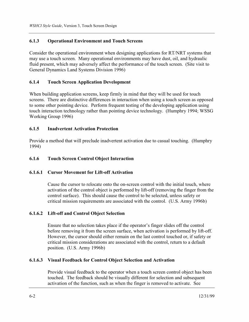
WSHCI Style Guide, Version 3, Touch Screen Design
6-2 12/31/99
6.1.3 Operational Environment and Touch Screens
Consider the operational environment when designing applications for RT/NRT systems thatmay use a touch screen. Many operational environments may have dust, oil, and hydraulicfluid present, which may adversely affect the performance of the touch screen. (Site visit toGeneral Dynamics Land Systems Division 1996)
6.1.4 Touch Screen Application Development
When building application screens, keep firmly in mind that they will be used for touchscreens. There are distinctive differences in interaction when using a touch screen as opposedto some other pointing device. Perform frequent testing of the developing application usingtouch interaction technology rather than pointing device technology. (Humphry 1994; WSSGWorking Group 1996)
6.1.5 Inadvertent Activation Protection
Provide a method that will preclude inadvertent activation due to casual touching. (Humphry1994)
6.1.6 Touch Screen Control Object Interaction
6.1.6.1 Cursor Movement for Lift-off Activation
Cause the cursor to relocate onto the on-screen control with the initial touch, whereactivation of the control object is performed by lift-off (removing the finger from thecontrol surface). This should cause the control to be selected, unless safety orcritical mission requirements are associated with the control. (U.S. Army 1996b)
6.1.6.2 Lift-off and Control Object Selection
Ensure that no selection takes place if the operator’s finger slides off the controlbefore removing it from the screen surface, when activation is performed by lift-off.However, the cursor should either remain on the last control touched or, if safety orcritical mission considerations are associated with the control, return to a defaultposition. (U.S. Army 1996b)
6.1.6.3 Visual Feedback for Control Object Selection and Activation
Provide visual feedback to the operator when a touch screen control object has beentouched. The feedback should be visually different for selection and subsequentactivation of the function, such as when the finger is removed to activate. See

WSHCI Style Guide, Version 3, Touch Screen Design
12/31/99 6-3
Figure 6.1 for an illustration. (Site visit to General Dynamics Land SystemsDivision 1996)
Automatic AutomaticAutomatic
Unpressed Selected Activated
Figure 6.1 Illustration of Visual Feedback for Touch Screen Control Objects
6.1.6.4 Layout of Touch Screens
Organize touch screen input buttons such that critical information is not coveredwhen the operator reaches across the display to activate a control. (WSSG WorkingGroup 1997)
6.1.7 Hardwiring of Critical Safety Controls
Consider using hardwired controls rather than touch screens for critical safety input.(Humphry 1994)
6.1.8 Touch Screens and Autocompletion Capability
Design touch screens through which the operator must perform frequent and complex dataentry with an autocompletion capability to reduce keystrokes, fatigue, and errors. Theoperator should have the capability to confirm the autocompletion as well as edit it.Autocompletion is where data fields are automatically filled in by the system from a databasebased on partial information supplied by the operator. (Gould 1989)
6.1.9 Touch Force Required for Piezoelectric and Resistance Touch Screens
Ensure that touch force is low for touch screens using technologies such as resistance andpiezoelectric to reduce fatigue. In general, resistance for these types of touch screens shouldbe similar to that for alphanumeric keyboards. See Table 6.1. (Gungl 1989; U.S. DoD 1996a)

WSHCI Style Guide, Version 3, Touch Screen Design
6-4 12/31/99
Table 6.1 Recommended Resistance for Touch Screen Control Activation
Numeric Alphanumeric Dual Function
Minimum 3.5 oz 0.9 oz 0.9 oz
Maximum 14.0 oz 5.3 oz 5.3 oz
6.1.10 Window Input Focus with Touch Screens
Where using multiple windows with touch screens, design windows such that they becomeactive and ready to receive input when touched. (U.S. Army 1996b)
6.2 CONTROL OBJECT DESIGN
Input through a touch screen is accomplished by contact with an on-screen control object(also referred to as a target). A control object is composed of the icon, symbol, or text thatidentifies the control, as well as a touch zone surrounding the object. The touch zoneencompasses the object and the area around the object in which action is enabled. In general,these touch screen control objects are like hardwired legend switches and should conform tothe relevant design criteria from MIL-STD-1472E (U.S. DoD 1996a).
(WSSG Working Group 1997)
6.2.1 Control Object Size
6.2.1.1 Control Object Size
Design touch screen control objects to be a minimum of 0.79 inches square. Forsystems where the operator will be operating the touch screen in vibratingenvironments or while wearing gloves (NBC, cold weather, fire retardant), thecontrol objects should be 1 inch square. See Figure 6.2 for an illustration. Smallercontrol objects may be used when the operator can adjust finger location and lift toactivate. (Benel and Stanton 1987; Plaisant 1991; Humphry 1994; U.S. Army1996b)
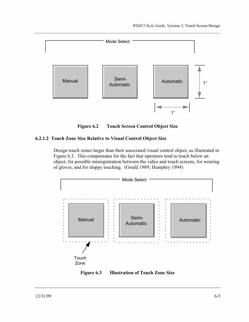
WSHCI Style Guide, Version 3, Touch Screen Design
12/31/99 6-5
Mode Select
Manual Semi-Automatic
Automatic
1”
1”
Figure 6.2 Touch Screen Control Object Size
6.2.1.2 Touch Zone Size Relative to Visual Control Object Size
Design touch zones larger than their associated visual control object, as illustrated inFigure 6.3. This compensates for the fact that operators tend to touch below anobject, for possible misregistration between the video and touch screens, for wearingof gloves, and for sloppy touching. (Gould 1989; Humphry 1994)
Mode Select
TouchZone
Manual Semi-Automatic
Automatic
Figure 6.3 Illustration of Touch Zone Size

WSHCI Style Guide, Version 3, Touch Screen Design
6-6 12/31/99
6.2.2 Control Object Separation
Separate touch screen control objects from each other and from the edge of the display by atleast 0.125 inches, and ensure that there is no overlapping of touch zones. (U.S. Army 1996b)
6.3 TOUCH SCREEN KEYBOARDS
6.3.1 Numeric Data Entry Keyboard for Touch Screens
Use a standard numeric keypad rather than a QWERTY keyboard layout when enteringnumeric data with a touch screen. (Coleman et al. 1991)
6.3.2 Alphanumeric Data Entry Keyboard for Touch Screens
Use standard or modified QWERTY keyboard layouts rather than an alphabetic keyboardlayout when entering alphanumeric data with a touch screen. (Coleman et al. 1991)However, the designer should be aware that some task dependencies indicate modifying thisguideline. For example, if speed and accuracy of data entry are most important, a QWERTYstyle keyboard will provide the best performance. If accuracy is more important than speed,an alphabetic keyboard may provide better accuracy but at a cost in terms of speed.(MacKenzie et al. 1994)

WSHCI Style Guide, Version 3, Helmet-Mounted Displays
12/31/99 7-1
7.0 HELMET-MOUNTED DISPLAYSHelmet-Mounted Displays (HMDs) are small, high-resolution displays that can replace Head-Down Displays (HDDs) and offer new methods of presenting visual information toindividuals on the battlefield. HMD systems project images in front of the wearer's eyes. Theimages are focused at a distance variable from 50 cm to infinity, depending on the application.Images cover about 20% of the immediate field of view (FOV), but remain transparent for thedirect view (normally 10%). Image transparency can be modified on user demand, and alarge unobstructed peripheral view is maintained. The emphasis of HMDs is to provideinformation to people where ordinary direct view displays are either inappropriate orimpractical. The following guidelines should be used to guide HMD design, though thedesigner should keep in mind that achieving the users’ requirements is the most critical factorto consider in designing an HMD. These guidelines are directed primarily at the capabilityfor HMDs to display information and not necessarily at see-through capability.
7.1 GENERAL
7.1.1 HMD Design for Situational Assessment
For situational assessment, consider using an HMD to:
a. Slave sensors and weapons to the helmet line of sight (LOS).
b. Display combat and critical vehicle/system status information.
(Adam 1992)
7.1.2 Use of Opaque Monocular HMDs
Consider using an opaque monocular HMD, where the HMD symbology and information willbe viewed against an additional layer of panel-mounted display information, e.g., tacticalmaps or detailed text displays. An opaque monocular HMD will reduce distracting clutter.(U.S. Army 1995g)
7.1.3 Design of Attitude Information Display for HMDs
When designing the HMD to include attitude information, consider presenting attitudeinformation with respect to the vehicle body-axis (non-conformal) rather than real world(conformal). Research indicates that a non-conformal presentation for attitude informationprovides better human performance. If conformal displays are used, ensure that the designeris aware that conformal displays may be difficult to interpret and confusing because of the

WSHCI Style Guide, Version 3, Helmet-Mounted Displays
7-2 12/31/99
symbology motion caused by vehicle and head movements. (Jones et al. 1992; WSSGWorking Group 1996)
7.1.4 Multi-Image HMD Design
Multi-image HMDs provide integrated visual input from multiple sources, such as a forward-looking infrared (FLIR) and a night vision sensor. When designing a multi-image sourceHMD, consider the following guidelines for minimizing potential negative impact on theuser’s performance:
a. FOV of a minimum of 40 degrees.
b. Center of gravity and weight that minimizes risk of injury and fatigue.
c. Real-world transmission greater than 70%.
d. One design for both day and night use.
e. Symbology contrast greater than 1.2 in daylight without using a visor.
f. Night vision goggles (NVG) gain greater than 2000.
g. Compatible with required NBC equipment.
h. Latency of image update relative to the real world.
Consider night vision integrity from the outset when designing a multi-image HMD system,taking into account all possible failure modes that might endanger the operator and systemthrough the loss of night vision.
(Bull 1992; WSSG Working Group 1996)
7.1.5 Potential Interference Sources for HMD Tracking Systems
Consider the following potential interference sources when designing an HMD for anRT/NRT tracking system application:
WSHCI Style Guide, Version 3, Helmet-Mounted Displays
12/31/99 7-3
a. Rotor chop/sun modulation.
b. Reflections/IR energy sources.
c. Limited motion box/helmet surface integrity.
d. Presence of cockpit/vehicle metal/changing metal location/magnetic fields.
(Ferrin 1991)
7.1.6 Image Processors for Infrared (IR)/Low Light Television (LLTV) Image Fusion
Consider the following when designing suitable image processors for infrared/low lighttelevision (IR/LLTV) image fusion used for viewing tasks on HMDs:
a. Defined obstacle edges are the most important requirement for vehicle navigationtasks.
b. High contrast enhancement, absence of blur, and good picture stability have to beachieved for visual recognition or identification of targets.
c. Good uniformity of the picture background is important for small target visualdetection.
(Balzarotti et al. 1994)
7.1.7 HMD Movement
Be aware that the HMD display can move through a large angle. If improperly implemented,this can lead to incorrect control inputs or aggravated spatial disorientation. (Newman andHaworth 1994)
7.1.8 Potential Reduced Situational Awareness
Consider, when designing HMDs, that there is a potential for this display to compete with theoutside world for the operator’s attention, leading to reduced situational awareness. As aresult, the operator may miss cues and other information from the environment. (NationalResearch Council [NRC] 1997)
7.1.9 Minimization of Occlusion of Environmental Sensing
Minimize occlusion of normal (visual and auditory) sensing of the environment, and enhancesensory input only when needed (e.g., NVG). (NRC 1997)

WSHCI Style Guide, Version 3, Helmet-Mounted Displays
7-4 12/31/99
7.1.10 Minimization of Cognitive Load
Minimize the cognitive load on the operator induced by the HMD by:
a. Providing integrated information.
b. Providing easy user input of information.
c. Minimizing memory requirements.
d. Reducing extraneous information.
e. Simplifying formats.
f. Minimizing tasks performed with the HMD.
g. Presenting information in a task-oriented sequence or grouping.
h. Providing information in the needed format.
(NRC 1997)
7.1.11 Use of Cueing for Situational Awareness Enhancement
Enhance situational awareness by providing salient cueing to direct the operator’s attention tothe most important information being displayed. (NRC 1997)
7.2 BINOCULAR HMD DESIGN
7.2.1 Use of Binocular HMD Design
Consider using binocular stereo displays where operators are required to follow a displayedpathway using an HMD. Stereopsis can improve tracking performance, though it may reducethe attention users apply to monitoring tasks. (Williams and Parrish 1990)
7.2.2 Partial Binocular-Overlap Imagery
Consider the following when designing partial binocular-overlap imagery for HMDs:

WSHCI Style Guide, Version 3, Helmet-Mounted Displays
12/31/99 7-5
a. Luminance Roll-Off. Eliminate the unnatural high-contrast edge.
b. Eye Assignments. Increase binocular correspondence of the HMD with the naturalworld.
c. Contour Lines. Compensate for the unnatural continuity of binocular/monocularimagery and the black surrounding surface.
d. Binocular Overlap. Use a binocular overlap of at least 40 degrees to reduce imagebreakup effects and eye discomfort, when using partially overlapping monocularimages to increase the field of view for NVGs.
Partial binocular-overlap, illustrated in Figure 7.1, is where an HMD presents the user with acentral binocular image flanked by monocular images.
(Melzer and Moffitt 1991; Alam et al. 1995)
Monocular Binocular Monocular
Figure 7.1 Illustration of Partial Binocular-Overlap
7.2.3 Adjustability
Consider providing operators with the ability to adjust image disparity to produce the bestdepth effect for the individual user of an HMD, as well as to adjust the diopter. (WSSGWorking Group 1996)

WSHCI Style Guide, Version 3, Helmet-Mounted Displays
7-6 12/31/99
7.2.4 Binocular HMD for Combined Day and Night Usage
Consider using binocular HMDs for combined day and night operations. Binocular HMDsoffer advantages over monocular systems when designing for day and night operations. Theyprovide superior contrast sensitivity, perceptual threshold, and visual acuity, and preventbinocular rivalry between the eyes. (Leger et al. 1993)
7.2.5 Design for Maximum Binocular Visual Capabilities
Consider using converging axes sensors when presenting images to each eye, wheremaximum binocular visual capabilities are required. With converging axes sensors, eachsensor is angled in towards the other. Converging axes sensors should:
a. Where possible, control sensor orientation by eye movements.
b. Use two integrated sensors to provide an extra margin of safety when usingbinocular HMDs.
(Leger et al. 1993)
7.2.6 Display of Symbology to Both Eyes
Ensure that HMDs are capable of displaying symbology to both eyes for binocularapplications. (Leger et al. 1993)
7.2.7 Bi-Ocular Versus Binocular HMD Use
Consider the use of bi-ocular instead of binocular displays in HMDs where stereoscopic depthjudgments are not critical. Bi-ocular displays present each eye with an identical image.(Rushton et al. 1994)
7.3 MONOCULAR HMD DESIGN
7.3.1 Use of Monocular HMDs
Use monocular HMDs when the operator needs one eye for real-world viewing and stereo-optic presentation is not required.
7.3.2 Monocular HMD Use for Night Operations
Although monocular HMDs may be used for daytime operations, use monocular HMDs fornight operations carefully. Whereas some data indicate that they preserve night vision

WSHCI Style Guide, Version 3, Helmet-Mounted Displays
12/31/99 7-7
adaptation in one eye (Lippert 1990), they may cause binocular rivalry for night videodisplays and are therefore undesirable at night. (Bohm and Schranner 1990; Bull 1990;Storey et al. 1994)
7.4 HMD OPTICS DESIGN
7.4.1 Optic Coatings
Consider the impact of optic coatings in the design process. Optic coatings should notsignificantly change outside world coloration. Specifically, white, red, green, and blue colorsshould be discernible. Where there may be an impact on color, such as that created whenusing laser protection coatings, consider this impact during the design to ensure that operatorperformance is not compromised. (Storey et al. 1994; WSSG Working Group 1996)
7.4.2 Adjustment of HMD Optics
Provide control over optics adjustment during operations, specifically interpupillary distance(IPD), eye relief, and vertical positioning. A 28-34 mm eye relief has been found to beacceptable, depending on overall system design. (Storey et al. 1994)
7.4.3 HMD Optics Transmissivity
Consider the following in designing HMD optics transmissivity:
a. For night use, provide a minimum of 30% transmissivity where direct vision is notimportant and vision of a HUD or vehicle instrumentation is required. However,50% to 70% transmissivity is preferred. Night is defined as the period from EndEvening Nautical Twilight (EENT) to Beginning Morning Nautical Twilight(BMNT).
b. For day use, provide 70% to 80% transmissivity to avoid reducing target detectionperformance.
(Bull 1990; Storey et al. 1994)
7.5 FIELD OF VIEW
There are arguments against the use of NVG HMDs because of their narrow FOV, which canblock the operator’s use of peripheral vision cues (Newman and Haworth 1994). Search timeincreases significantly as the size of the FOV becomes smaller. Some research indicates thatthe size of the FOV affects the ability to acquire spatial information of one's surroundings.Consider the following paragraphs for the design of HMD FOV. (Venturino and Kunze 1989)

WSHCI Style Guide, Version 3, Helmet-Mounted Displays
7-8 12/31/99
7.5.1 Field of View Size
Design the HMD with the following FOV:
a. Minimum FOV - 30 degrees. This is most appropriate for day-optimized and videosensor HMDs. (Storey et al. 1994)
b. Desired minimum FOV - 40 degrees. (Bohm and Schranner 1990; Bull 1990;Leger et al. 1993; Storey et al. 1994)
c. NVG FOV – 32 degrees for tasks such as targeting and sighting, 40 degrees forgeneral tasks such as patrolling, surveillance, and vehicle operations. A 60 degreeFOV provides little benefit in performance for their cost in weight and size. (ARL-HRED 1996)
7.5.2 Devices to HMDs
Consider, when widening the operator’s FOV by slaving a sensor device such as a FLIR to theLOS of the HMD, that time lags between the operator’s head movement and the display of thesensor output can seriously impair the ability to derive control-oriented information from thevisual field. The operator may tend to minimize head rotations, which diminishes the wide-angle coverage provided by the slaving system, thereby impairing search performance andspatial orientation. (Grunwald et al. 1991)
7.5.3 Location of Display Symbology in the FOV
Keep symbology display within the central 25 to 27 degrees of the display FOV to precludeeye strain but be careful not to over-clutter the central part of the display, which can degradeviewing of the outside world. (Storey et al. 1994; WSSG Working Group 1996)
7.5.4 Resolution
Ensure that the resolution of HMDs optimizes human visual performance for the task beingperformed. Many factors can contribute to visual performance, including the following:
7.5.4.1 Line Width for Viewing Tasks
For day use, design an HMD to provide a minimum display resolution of 1milliradian line width as well as appropriate distance between lines. At night, higherresolutions may be required to make full use of FLIR capabilities. (Bohm andSchranner 1990; Bull 1990)
WSHCI Style Guide, Version 3, Helmet-Mounted Displays
12/31/99 7-9
7.5.4.2 Design for Spatial Resolution Tasks
When designing an HMD for spatial resolution tasks, use a high-resolution display(e.g., 640 x 480) for the best operator performance. (Sharkey et al. 1995)
7.5.5 Image Brightness
Design HMDs for daytime use with a minimum contrast ratio of 1:2; preferably 1.3:1. Atnight, brightness should be adjustable to allow viewing of the display without loss of nightvision (about 3 footLamberts) and without compromising survivability. (Bull 1990; WSSGWorking Group 1996)
7.5.6 Shades of Gray
Design monochromatic HMD displays to provide a minimum of 6 shades of gray foralphanumeric and graphical information. If possible, design the HMD display to support 9 to10 shades of gray for viewing more complex sensor data. (Bohm and Schranner 1990;Honeywell Technology Center 1995)
7.6 PHYSICAL DESIGN OF HMDs
7.6.1 General
Ensure that HMD designs:
a. Are comfortable and do not restrict head movements.
b. Do not otherwise compromise safety, e.g., impact and penetration protection, eyeand hearing protection.
(Cameron 1994; Storey et al. 1994; Honeywell Technology Center 1995; WSSG WorkingGroup 1996)
7.6.2 Weight
Actual weight of HMDs will be driven by mission requirements. Consider the following inthe design of HMDs:
WSHCI Style Guide, Version 3, Helmet-Mounted Displays
7-10 12/31/99
a. Ideal weight is between 3.5 lb. and 3.99 lb. or less to reduce operator fatigue. (Perryet al. 1993; Burley and LaRussa 1990)
b. Night-equipped HMDs, which will weigh more than day HMDs due to additionaloptics, should weigh less than 4.5 lb. (Cameron 1994)
c. Total head-supported weight (e.g., helmet, HMD, etc.) should be less than 5.3 lb.,because operator performance is degraded in vibrating environments after 1 hourwith greater weights. (Storey et al. 1994)
7.6.3 HMD Weight Distribution
7.6.3.1 Weight Distribution
Ensure that weight distribution of an HMD does not cause significant out-of-balanceconditions with respect to the neck pivot point. (Cameron 1994)
7.6.3.2 Mass and Center of Gravity
Ensure that the mass and center of gravity of HMDs do not cause fatigue or headmobility problems. Ideally, the mass should be centered low on the helmet, near thehead pivot point. (Leger et al. 1993; Newman and Haworth 1994; HoneywellTechnology Center 1995)
7.6.4 HMD Visor and Optical Configuration Design
Use the following guidelines to aid design when visors are used on HMDs. Not all HMDs usevisors.
7.6.4.1 Visor Orientation and Curvature
Ensure that the visor’s orientation and curvature:
a. Reflect the light projected from the optical assembly to the operator's eye.
b. Keep the size of the solution envelope as small as possible, in order to keep to aminimum the limitations on operator's head movements in restricted space.
(Gilboa 1991)
WSHCI Style Guide, Version 3, Helmet-Mounted Displays
12/31/99 7-11
7.6.4.2 Curvature and Eye Relief Values
In general, when visors are used, design the HMD with appropriate curvature andeye relief values. (Gilboa 1991)
7.6.4.3 Handedness and HMD Visors
Where visors are used on HMDs, ensure that visors are operable with either hand.(Cameron 1994)
7.6.5 HMD Design for Safety
Consider the following safety concerns when designing an HMD:
a. Design the HMD used for daytime operations so that it does not obstruct theoperator’s view of the outside scene. Otherwise, the HMD can have an impact onthe operator’s ability to safely perform tasks. Ensure that, if one eye is obstructed,the other has a clear view. (Bull 1990)
b. Note that some types of display devices require high voltage to operate. The cablesrequired to conduct this high voltage to the helmets may create a safety issue.(Honeywell Technology Center 1995)
c. Ensure that cables running to the helmet have a quick disconnect. (HoneywellTechnology Center 1995)
d. If possible, design the HMD such that no part is located on or near the top of thehelmet, to preclude damage due to impact on hatches or other parts of crewcompartments. (Honeywell Technology Center 1995)
e. Eliminate cables, snaps, etc. from snagging or interfering with other equipment orcrew operations. (WSSG Working Group 1996)
7.6.6 Minimization of Soldier Distraction
Design should minimize distracting operator attention by allowing the removal of the sensor,displacement of the display out of the line of sight, or in other ways to ensure a clear view ofthe outside environment. (NRC 1997)
7.6.7 Design for Dismounted Operations
Consider the following when designing HMDs for dismounted operations:

WSHCI Style Guide, Version 3, Helmet-Mounted Displays
7-12 12/31/99
a. There is no support for the head or body in dismounted operations to compensate forweight and center of gravity.
b. Dismounted users must move and take cover rapidly.
c. There will be a significant number of posture changes, including partial crouches,while moving fast. The weight distribution must accommodate these posturalchanges without risk of injury or inducing fatigue.
(NRC 1997)
7.6.8 Helmet Movement Impact on Optics
Where using electro-optical systems, consider that the helmet should not be free to move onthe wearer’s head. If this is unavoidable, ensure that the helmet can be resettled quickly andeasily. (NRC 1997)
7.7 VIBRATION AND HMDs
7.7.1 Design for Vibrating Environments
Design HMDs with the understanding that vibration may be present in the operator’senvironment. In particular, human task performance on tracking tasks is the worst at 4 Hz.(Sharkey et al. 1995)
7.7.2 Attenuation of Head Motion
If HMDs are used in vehicles, include engineering features that attenuate head motion in the 4Hz range, particularly if the seating position requires head support. This will improvetracking performance and reduce the chances of motion sickness. (Sharkey et al. 1995)
7.7.3 Adaptive Filtering
When using adaptive filtering to estimate head motion due to platform accelerations, considerusing complementary filtering methods. These methods have been effective in compensatingfor the image stabilization error due to sampling delays of HMD position and orientationmeasurements. The complementary filtering method combines the measurements of the headposition and orientation system with measurements of the angular acceleration of the head.(Merhav and Velger 1991)

WSHCI Style Guide, Version 3, Head-Up Displays
12/31/99 8-1
8.0 HEAD-UP DISPLAYSHead-Up Displays (HUD) are fixed displays mounted at the top of aircraft and ground vehicleinstrument panels. Computer-generated information is projected onto a vehicle’s windscreenor other reflective surface and, as the operator looks through the glass, both the scene in frontof the vehicle and the HUD-projected information are viewed. This arrangement allows theoperator to see important information without having to look down at the instrument panel.When HUDs have integrated sensors, synthetic images of objects can be displayed, allowingoperators to “see” objects that may not be visible to their unaided eyes.
The following guidelines can be used to aid in the development and implementation of HUDsin aircraft and ground vehicles. Designers of HUDs need to be aware of the differencesbetween aircraft usage and ground vehicle usage. Ground vehicles have dense and variedarrays of obstacles in the backgrounds, whereas aircraft have relatively stable backgroundswith less complexity (Ward et al. 1994). Additional information may be found in thefollowing documents:
• Improvement of Head-Up Display Standards, Volume 1: Head-Up Display DesignGuide (Newman 1987)
• Human Factors Aspects of Using Head-Up Displays in Automobiles: A Review ofthe Literature (Gish and Staplin 1995)
• Head-Up Displays for Automotive Applications (Harrison 1994).
8.1 GENERAL
8.1.1 HUD Advantages over Head-Down Display (HDD)
Consider the advantages of HUDs over HDDs. In general, the advantages of a HUD over anHDD are the reduction of eye movement and the reduction of eye refocusing, as well asimproved precision aiming. (Knoll and Konig 1992; Inuzuka et al. 1991; WSSG WorkingGroup 1997)
8.1.2 Minimization of Presented Information
Minimize the information presented on a HUD to reduce clutter and to avoid restricting thevisibility of objects in the real world—typically the far domain. (Newman and Haworth1994)

WSHCI Style Guide, Version 3, Head-Up Displays
8-2 12/31/99
8.1.3 Use of Multiple Cues
Use multiple cues, such as size and color/gray scale coding, with 2-D or 3-D HUDs toimprove spatial-perceptual performance. (Reising and Mazur 1990)
8.1.4 Perceptual Segregation of Near and Far Domain Cues
If a task requires that the operator focus exclusively on cues in either the near or far domainswhen using a HUD, maximize the perceptual segregation of the two domains. If cues arerequired in both domains, be aware that the HUD may interfere with processing informationfrom the far domain and lead to task fixation to the detriment of other concurrent tasks, suchas piloting or driving. (McCann et al. 1993)
8.1.5 Depth Cues
Consider using depth cues such as stereo 3-D, aerial perspective (symbol becomes more grayor less bright with depth), and familiar object size to improve operator performance, forexample, improving the speed and accuracy in determining locations of friendly, enemy, andunknown aircraft. (Mazur and Reising 1990; WSSG Working Group 1997)
8.1.6 3-D Cues
Consider using 3-D HUD displays if depth perception is required and monocular depth cuesare not available when presenting information. Monocular cues provide perceived depthperception for one eye through linear perspective, interposition, familiar object size, etc.(Reising and Mazur 1990; WSSG Working Group 1997)
8.1.7 Compatibility with HDD
Design HUDs to display information that is compatible with HDDs. This will ensureconsistency of operation within the system. (Newman 1987)
8.1.8 Nonreflectivity of HUDs
Ensure that HUDs are designed to be nonreflective to the outside world, to reduce anyexternal visual signature. (WSSG Working Group 1996)
WSHCI Style Guide, Version 3, Head-Up Displays
12/31/99 8-3
8.1.9 Placement of HUDs
Place HUDs as close as possible to the horizontal center position and eye level relative to theoperator. This enhances user performance. (Okabayashi et al. 1989; WSSG Working Group1996)
8.1.10 Information Projection with HUD Systems
Design HUDs so that the information is projected against the least complex visual field.HUDs designed for ground vehicles should be projected down towards the roadway, whichhas a less complex visual field. For aircraft, where the general background is less complex,design HUDs so the visual field is projected higher. (Ward et al. 1994)
8.2 SYMBOLOGY FOR HUDs
8.2.1 Use of HDD Symbology
Use caution when designing symbols for HUDs that mimic head-down displays, because theycan result in cluttered displays or cause confusion regarding control techniques. (Newmanand Haworth 1994)
8.2.2 Information Origin Certainty
Design symbols and information presented on a HUD to ensure that operators have nouncertainty about the origin of the information being displayed. (Newman and Haworth1994)
8.2.3 Overuse of Non-Conformal Symbology
Avoid overusing non-conformal symbology on HUDs. Non-conformal symbology refers tosymbology that is not consistent with its far domain analog, e.g., symbology that is consistentwith the vehicle body orientation rather than the horizon orientation. The design goal toreduce operator scanning can be neutralized or defeated by too much clutter from non-conformal symbology. (Wickens and Long 1994)
8.2.4 Declutter Capability
Provide the operator with the capability to declutter the symbology and/or informationdisplayed on a HUD. (Newman 1987)

WSHCI Style Guide, Version 3, Head-Up Displays
8-4 12/31/99
8.3 USE OF COLOR IN HUDs
Use color sparingly in HUDs. Trade-offs must be made by the designer in terms of costsversus a potential minimal performance enhancement. Although operators like colorsubjectively, color appears to have little positive impact on performance when using HUDs.(Dudfield 1991)
8.3.1 Color and HUD Coatings
Be aware when using color that coatings used on HUDs, such as those used to reducereflectivity, may have an impact on the perception of color. (WSSG Working Group 1996)
8.3.2 Color Control and HUD Background
Provide the operator with the capability to change the color codes and contrast to adjust forvarying backgrounds. (WSSG Working Group 1996)
8.4 FIELD OF VIEW
Design the FOV for HUDs as wide and as tall as possible, depending on the vehicle. Groundvehicles need wide FOVs, whereas aircraft need wide and high FOVs. Consider thefollowing:
a. In general, the suggested minimum total FOV of a HUD for aviation systems shouldbe 25 to 30 degrees azimuth and 22 to 25 degrees elevation.
b. Data are more sparse for ground systems. In general, many of the commercialHUDs being used in automobiles have a much narrower FOV, due in part to costconsiderations as well as the minimal information being displayed. The FOV forground vehicle HUDs should be designed to meet system and user requirements.
(Newman 1987; Harrison 1994; Wisely 1994; Gish and Staplin 1995)
8.5 RASTER IMAGE DESIGN
8.5.1 Visual Raster Image Contrast and Refresh
Present visual raster images (i.e., video images) used in HUDs using a high raster image-to-background contrast ratio and appropriate refresh rates. (Todd et al. 1995)
WSHCI Style Guide, Version 3, Head-Up Displays
12/31/99 8-5
8.5.2 HUD Raster Image Luminance
Ensure that HUD raster image luminance is approximately 50% of the forward sceneluminance. If the HUD is restricted to observation of familiar terrain, such as a runway orroadway, with high-contrast edges, center line, and markings, the luminance level should beabout 15% of the forward scene luminance. (Lloyd and Reinhart 1993)
8.6 DYNAMIC RESPONSE
Design HUDs so that symbology and other displayed information are stable.
8.6.1 Flicker
Ensure that symbols show no discernible flicker. (Newman 1987)
8.6.2 Jitter
Ensure that symbols have no discernible jitter. Jitter is considered motion at frequenciesabove 0.25 Hz. (Newman 1987)
8.7 HUD AND FLIR IMAGES
When using forward looking infrared (FLIR) images on a HUD, consider the followingguidelines.
8.7.1 FLIR and Night Vision Goggles
When the operator will be viewing FLIR images on a HUD concurrently with use of nightvision goggles (NVGs), either provide a mechanism to turn off the NVGs, or use NVGs thatallow vision of the HUD directly through the NVG (straight through) rather than having theimage presented indirectly through combiner lenses (folded-optic). Data suggest that viewingthe FLIR image through the folded-optic NVGs can be confusing to the operator. (Evans1991)
8.7.2 FLIR and HUD Symbology
Consider, when designing systems to display FLIR images on HUDs, providing a dark borderaround white HUD symbols. FLIR images can sometimes be presented as dark “hot-zones”on a white “cool-zone” background. This may make it difficult to see the HUD symbology.(Evans 1991)

WSHCI Style Guide, Version 3, Head-Up Displays
8-6 12/31/99
This page intentionally left blank.
WSHCI Style Guide, Version 3, Auditory Human-Computer Interaction
12/31/99 9-1
9.0 AUDITORY HUMAN-COMPUTER INTERACTION
This section addresses interactions between weapon systems and users through non-verbalacoustic signals and speech interaction. In this context, signals include devices such as alarmsand other non-verbal auditory presentations that convey information through their tonal,intensity, or spatial characteristics. Speech technologies include speech and speakerrecognition, speech synthesis and digitized voice. The intent of these technologies is tofacilitate linguistic communications between users and machines when the use of hands andeyes is constrained due to other task-related requirements. Speech interfaces are also usefulwhen users do not understand system interfaces and input devices or when users lack certainwritten language skills.
Designers of auditory signals and speech communications devices must be cognizant offactors that can degrade the subjective intelligibility of acoustic signals. Some of these, suchas background noise and degraded user and communications capabilities, might beparticularly important under conditions in which RT/NRT systems are likely to be used. Inaddition, designers need to be aware that there are differences between the presentation ofauditory signals through loudspeakers compared to headsets.
9.1 GENERAL
9.1.1 Limits to the Number of Auditory Signals
Although a large number of auditory signals can be learned, use no more than six immediateaction signals and two attention signals to minimize learning and training requirements. Thisassumes that distinct temporal and spectral patterns are used, perceived urgency of warningsmatches their priority, and warning sounds are followed by keyword speech warnings.(General Dynamics 1986; NRC 1997; WSSG Working Group 1999)
9.1.2 Selection of Auditory Displays
Note that three basic types of auditory signals can be used for auditory displays: periodictones, non-periodic complex sounds, and speech. Table 9.1 provides an illustration of theutility of each of these signal types for different functions, though this guidance is mostappropriate for single signal presentation. The designer will need to consider trade-offs whendesigning for a complex auditory environment. (WSSG Working Group 1999)

WSHCI Style Guide, Version 3, Auditory Human-Computer Interaction
9-2 12/31/99
Table 9.1 Guidance for Selection of Audio Signals Based on Function
Types of SignalFunction Tones (Periodic) Complex Sounds
(Non-Periodic)Speech
Quantitativeindication
POORMaximum of 5 to 6tones absolutelyrecognizable.
POORInterpolationbetween signalsinaccurate.
GOODMinimum time and errorin obtaining exact valuein terms compatible withresponse.
Qualitativeindication
POOR-TO-FAIR Difficult to judgeapproximate valueand direction ofdeviation from nullsetting unlesspresented in closetemporal sequence.
POORDifficult to judgeapproximatedeviation fromdesired value.
GOODInformation concerningdisplacement, direction,and rate presented inform compatible withrequired response.
Status indication GOODStart and stoptiming. Continuousinformation whererate of change ofinput is low.
GOODEspecially suitablefor irregularlyoccurring signals(e.g., alarm signals).
POORInefficient: more easilymasked; problem ofrepeatability.
Tracking FAIRNull position easilymonitored; problemof signal-responsecompatibility.
POORRequired qualitativeindications difficultto provide.
GOODMeaning intrinsic insignal.
General Good for automaticcommunication oflimited information.Meaning must belearned. Easilygenerated.
Some soundsavailable withcommonmeaning(e.g., firebell). Easilygenerated.
Most effective for rapid(but not automatic)communication ofcomplex,multidimensionalinformation. Meaningintrinsic in signal andcontext whenstandardized. Minimumof new learningrequired.
Adapted from National Research Council 1997

WSHCI Style Guide, Version 3, Auditory Human-Computer Interaction
12/31/99 9-3
9.1.3 Operator Request for Repeat of Signal
Provide the operator with the capability to request a repeat of the nonverbal or verbal auditorysignal. (Obermayer and Campbell 1994)
9.1.4 Redundant Cues for Auditory Signals
Ensure that auditory display signals are always accompanied by a redundant visual indication.(Obermayer and Campbell 1994; U.S. Army 1995g)
9.1.5 Redundant Cues for Visual Signals
Use auditory cues to augment visual cues for out-of-tolerance conditions, when operators aremonitoring rather than actively controlling automated actions. (Wickens and Kessel 1979)
9.1.6 Timing of Tones and Voice Signals
When using tones concurrently with voice annunciation, begin both simultaneously, with thetone terminating 1 second after the voice annunciation. (U.S. Army 1995g)
9.1.7 Lack of Data Transmission Interference
Ensure that digital data transmission does not interfere with voice communication or auditorysignals and is not masked by background noise. (U.S. Army 1993)
9.1.8 Speech Intelligibility
Design systems that use speech presentations to provide a degree of speech intelligibilityconsistent with listening conditions, user characteristics, and mission requirements.
9.1.8.1 Intelligibility Criteria
Design RT/NRT systems so that they meet the speech intelligibility criteria in Table9.2. (U.S. DoD 1996a)

WSHCI Style Guide, Version 3, Auditory Human-Computer Interaction
9-4 12/31/99
Table 9.2 Intelligibility Criteria for Voice Communications Systems
Score
Communications Requirement PB* MRT** AI***
Exceptionally high intelligibility; separate syllables understood 90% 97% 0.7
Normal acceptable intelligibility; about 98% of sentencescorrectly heard; single digits understood
75% 91% 0.5
Minimally acceptable intelligibility; about 90% sentencescorrectly heard (not acceptable for operational equipment)
43% 75% 0.3
* Phonetically balanced** Modified rhyme test*** Articulation index
(Adapted from MIL-STD-1472E [U.S. DoD 1996a])
9.1.8.2 Testing Requirements
When very high degrees of intelligibility are required, test systems using the targetword sets (i.e., words the user is expected to understand when using an applicationthat includes speech output) and one of the following methods: phoneticallybalanced monosyllabic word intelligibility methods as outlined in ANSI S3.2-1989[R1995] (ANSI 1995) and the articulation index described in ANSI S3.5-1969[R1986] (ANSI 1986). For less stringent requirements, use modified rhymetesting or similar methods. (U.S. DoD 1981)
9.1.8.3 Use of Prerecorded Speech
Consider using prerecorded speech rather than synthesized speech when highdegrees of intelligibility are required. (Streeter 1988)
9.1.9 Avoiding Masking of Auditory Signals
Avoid potential masking of one auditory signal by another through:
WSHCI Style Guide, Version 3, Auditory Human-Computer Interaction
12/31/99 9-5
a. Considering how multiple auditory alarms and warnings will interact with eachother. (Stuart 1995)
b. Ensuring that multiple auditory alarms and warnings are outside the critical maskingband. (Stuart 1995)
c. Maintaining adequate spatial separation between different sound sources. (Stuart1995)
d. Providing the ability to emphasize some signals and de-emphasize other signalsbased on priority. (WSSG Working Group 1999)
9.1.10 Use of Auditory Interfaces
Use auditory displays for interfaces that do not usually get direct visual attention from theuser or where visual interaction is not possible. (Hindus et al. 1995; Stuart 1995)
9.1.11 Active Noise Reduction
In high ambient noise environments, use active noise reduction (ANR). In ANR twomicrophones are used to try to compensate for noise environments. One picks up thespeaker’s voice and one picks up the ambient noise. The input from the second is used tocancel out the noise, thereby enhancing the speaker’s input. (Takahashi, et al. 1995; WSSGWorking Group 1999).
9.1.12 Use of a Common Lexicon
When using speech for signaling, use words from a lexicon familiar to the target audience toreduce cognitive demands for recognition of the signal. (Companion and Epp 1997)
9.2 NONVERBAL SIGNALS
9.2.1 Use of Nonverbal Auditory Signals
Use nonverbal auditory signals for applications when their immediate discrimination is notcritical to personnel safety or system performance. Ensure that nonverbal auditory signals areintuitive in nature. Limit the number of nonverbal signals to ensure rapid and correctinterpretation by the operator under mission conditions. (Obermayer and Campbell 1994;WSSG Working Group 1996)

WSHCI Style Guide, Version 3, Auditory Human-Computer Interaction
9-6 12/31/99
9.2.2 Control of Auditory Signal
Provide the operator with the capability to control or disable the audio signal volume.However, consider the following:
a. Do not allow the disabling of mission and safety critical signals.
b. Design the volume control to ensure that the operator cannot inadvertently decreasethe volume level to where it is inaudible.
c. Ensure that the volume control allows adjustment of the signal to compensate fornoisy environments, but does not exceed the noise limits set in MIL-STD-1472E(U.S. DoD 1996a) and MIL-STD-882C (U.S. DOD 1996c).
(Obermayer and Campbell 1994; U.S. Army 1995g; WSSG Working Group 1996)
9.2.3 Auditory Signals - Tonal Display Design
Design tonal displays according to the following guidelines:
9.2.3.1 Pitch
Design pitch of warning sounds to be between 150-1000 hertz (Hz). (NRC 1997)
9.2.3.2 Frequency Components
Include at least 4 dominant frequency components within the first 10 harmonics ofsignals. This will help minimize masking effects, as well as pitch and qualitychanges during masking, and maximize the number of distinctive signals that can begenerated. (NRC 1997)
9.2.3.3 Harmonic Spectra
Ensure that signals have harmonic rather than inharmonic spectra.
WSHCI Style Guide, Version 3, Auditory Human-Computer Interaction
12/31/99 9-7
a. Lower priority - most energy in the 1st five harmonics.
b. Higher priority - energy in 6 to 10 harmonics.
c. High priority - can make distinctive by adding a small number of inharmoniccomponents.
(NRC 1997)
9.2.3.4 Frequency Range
Restrict frequency range to within 500-5000 Hz, with the dominant ones within1000-4000 Hz. (NRC 1997)
9.2.4 Selection of Tonal Frequencies for Background Noise
Select tonal frequencies with minimal noise masking when background noise is present.Ensure that the major concentration of energy is between 250 and 2500 Hz. (GeneralDynamics 1986)
9.2.5 Signal Modulation
To demand attention, modulate the signal to give intermittent beeps or to make the pitch riseand fall at a rate of about 1 to 3 cycles per second. (General Dynamics 1986)
9.2.6 Temporal Form and Shape of Auditory Displays
Temporal form and shape are important factors in detectability of, coding of, and listenerreaction to auditory displays. Consider the following in designing temporal form and shape:
a. Near-optimum envelope parameters are a minimum of 100 milliseconds (ms)duration, 25 ms rise and fall time, and quarter sine shaping.
b. Onset rates should be less than 1 decibels (dB)/ms, with final level falling below 90dB.
c. Use a variety of temporal patterns in order to minimize confusion.
d. Code urgency or priority with pulse rate, i.e., high pulse rate for high priority.
(NRC 1997)

WSHCI Style Guide, Version 3, Auditory Human-Computer Interaction
9-8 12/31/99
9.3 SPEECH OUTPUT
9.3.1 When to Use Speech Output
Consider using speech output when the:
a. Message is short, simple and will not need to be referred to again.
b. Message calls for immediate action.
c. Inappropriate for a visual display.
d. Task requires continuous physical movement by the operator.
(Cowley, Miles and Jones 1990)
9.3.2 Synchronization of Speech and Visual Warnings
Ensure that synthetic speech warnings used in conjunction with visual warnings aresynchronized. (Hansen and Bou-Ghazale 1995)
9.3.3 Vowel Versus Consonant Sounds in High Noise Environments
In high noise environments, design speech output systems so that vowel sound levels arehigher than the background noise and consonants are detectable. (NRC 1997)
9.3.4 Polysyllabic Versus Monosyllabic Words
In designing speech output systems, consider that polysyllabic words are more intelligiblethan monosyllabic words, as are word sentences over words in isolation. (NRC 1997)
9.3.5 Speech Output in Alarm Handling
a. Use speech and text simultaneously to provide fault diagnostic information in alarmdisplays.
b. Do not use speech alone as a means to provide alarm information – fault correctionwill be impaired.
(Stanton and Baber 1997)

WSHCI Style Guide, Version 3, Auditory Human-Computer Interaction
12/31/99 9-9
9.4 3-D AUDITORY LOCALIZATION
3-D auditory localization refers to providing auditory cues that assist the operator in orientingtowards the physical location of a source. For example, auditory cues might be used toindicate the direction of a threat.
9.4.1 Use of 3-D Auditory Localization
Consider using 3-D localization of the auditory signal to cue the operator on the directionfrom which a target or signal is coming, or to help localize where the operator needs to focusattention. When using 3-D localization through headsets, include a mechanism for trackingthe operators’ head location with respect to the task being performed to ensure appropriateorientation of the 3-D signal. (Begault 1993; U.S. Army 1995g; Elias 1996; WSSG WorkingGroup 1997, 1999)
9.4.2 3-D Auditory Localization and Stimulus-Response Compatibility
Consider using 3-D localization to maximize Stimulus-Response Compatibility (SCR). Thisis accomplished by matching 3-D localization representative of spatial processing when amanual response is required and non-directional audio when a verbal response is required.For example, where selection of a button is required when an alert condition occurs, considerusing 3-D localization to draw user attention to the location of the button. (Wickens, Sandry,and Vidulich, 1983, Wickens, 1984b)
9.4.3 Auditory Preview
If implementing auditory preview for targets not yet in the visual field, ensure that theperceived velocity of the auditory signal is either consistent with or proceeds the target’sapproach to the visual field. Do not allow the auditory signal to lag behind the target.Auditory preview consists of an auditory signal that indicates to a operator the direction andapproaching speed of a target that is not yet visible to the eye, either through a display ornaked eye. (Elias 1995)
9.5 SPEECH RECOGNITION
The two basic types of speech recognition systems are: speaker-dependent and speaker-independent. Speaker-independent approaches are designed to accommodate differences inindividual speech patterns. Most commercial products in this category are trained to respondto a relatively smaller collection of words and phrases. Examples in this category includetelephone order entry and dialing assistance applications and simple speech-actuated controldevices. Improvements in speech recognition technology will result in more robust speaker-

WSHCI Style Guide, Version 3, Auditory Human-Computer Interaction
9-10 12/31/99
independent applications but, at the present time, these technologies tend to be more limitedthan speaker-dependent approaches.
The designer should keep in mind that weapon system aural environments include veryadverse conditions for implementing speech recognition. This includes poor signal to noiseratios, very variable background noise conditions, and significant stress on the speaker -causing voice pattern changes. These conditions can make it very difficult to achieve highrecognition accuracy.
9.5.1 General Design Considerations for Speech Recognition
Consider the following when designing a speech recognition system:
a. Prior to deciding whether to implement a speech recognition element into a weaponsystem, perform a thorough analysis of the costs and benefits of this technology.Among the questions that need to be considered are the following:
• What are the benefits of using speech versus other means of interaction, e.g. doesit support operator performance? (Steeneken 1996)
• What functions and/or tasks are to be mediated using speech recognition?(Steeneken 1996)
• Who are the speakers(s)? This includes determining if there will be multipleusers or a single user, and intellectual level of the users. (Steeneken 1996)
• What are the benefits versus costs of implementing speech recognition?(Steeneken 1996)
• Does the speech recognition system map to the task and is it appropriate to thecorresponding visual user interface. (WSSG Working Group 1999)
b. Ensure that the design includes the voice transducer in the speech recognitionsystem. Because the direction of the incoming speech signal and the distancebetween the source and the microphone determine the quality of the signal captured,designers need to include the voice transducer in the speech recognition systemdesign.
c. For all systemsand in particular those that must be trained to a specific speaker’svoice (enrollment)consider the potential effects of within-speaker variability.Factors that can cause changes in speech include physical and physiologicalcharacteristics of the speaker, voice quality, rate of speaking, prosody (i.e., accenting
WSHCI Style Guide, Version 3, Auditory Human-Computer Interaction
12/31/99 9-11
different syllables and words), and degraded modes, such as wearing MOPPequipment, etc.
d. Design speech systems to degrade gracefully when operating under unusualconditions, and consider methods for automatically adapting system characteristicsto changing conditions, such as vibration and background noise, and new humanspeakers.
e. When designing systems for use by native and non-native speakers, consider thepossible effects of dialects and multiple word pronunciations on the accuracy ofspeech recognition
f. Limit vocabulary size to what is required for the tasks. Provide a means fordetecting out-of-vocabulary or low certainty words or phrases and alerting the userwhen the meanings are not clearly understood by the system. Do not requirecomplete sentences and allow for multi-grammar design where certain words are notrecognized by the system based on user, task, or mode of operation. Consider thatthe use of a standard military lexicon that includes vocabulary specific to the targetaudience will significantly improve the accuracy of speech recognition.
g. When using an isolated word recognition system, improve recognition by usingkeyword spotting. In keyword spotting, the system is trained/designed to recognizecertain keywords that are embedded in redundant utterances of conversationalspeech and in noisy speech. This improves performance for spontaneous speech.Spontaneous speech is different from the read speech typically used for systemtraining in that a number of other “speech events” are embedded in the signal. Theseevents include false starts, interjections (i.e., “uh”), disfluencies, and out-of-vocabulary words. (Lee and Rabiner 1995; Takahashi, et al. 1995).
h. Note that acoustic mismatches between the actual environment and the environmentused for training the system can degrade performance. This can be a significantproblem for RT/NRT applications because of the number of variables that can affectthe acoustic environment.
i. Note that microphones used in tactical environments may have a limited frequencyrange and peak clip inflections and other aspects of speech. (WSSG Working Group1996)
j. Provide the ability for the operator to disable speech recognition systems for someoperational modes, such as those that require silence. (WSSG Working Group1999)
WSHCI Style Guide, Version 3, Auditory Human-Computer Interaction
9-12 12/31/99
9.5.2 Use of Automatic Speech Recognition Systems
Use automatic speech recognition (ASR) only where:
a. The resulting action is not mission critical.
b. An alternative control system is available.
(Coueffin et al. 1983)
9.5.3 Speech Recognition Interaction with Other Primary Tasks
Consider the possible ramifications on other tasks when selecting speech recognition systems.While data suggest that concurrent use of speech recognition with a primary visual task, i.e.,piloting or driving may degrade performance on the primary task, these possible limitationsshould be balanced against the potential benefits when operators must use their vision andhands for other tasks. (Dudfield 1991)
9.5.4 Environmental Impact on Speech Recognition
In the design, consider the environmental impact on speech recognition. When consideringthe implementation of a speech recognition system in an RT/NRT system, designers should beaware that the operational environment may contain high levels of noise and vibration, requirespeech through a mask, and induce stress in the operator, thus changing voice characteristicsand making speech recognition systems less reliable. (Gordon 1990; U.S. Army 1995g; Sitevisit General Dynamics Land Systems Division 1996; WSSG Working Group 1997)
9.5.5 Whispered Speech
Consider, in designing speech recognition for direct voice input (DVI) for RT/NRT systems,that the system may need to respond accurately using a microphone mounted in theworkspace to whispered speech through a respirator or MOPP mask or due to whisperedmodes of operation. (Hughes and King 1989; WSSG Working Group 1997, 1999)
9.5.6 Fail-Safe Protocols
Use fail-safe protocols in the design of DVI systems that will preclude potential catastrophicresults from errors in speech recognition. (Hughes and King 1989)

WSHCI Style Guide, Version 3, Auditory Human-Computer Interaction
12/31/99 9-13
9.5.7 Redundant or Alternate Means for Input
Ensure that speech recognition used for data input or command entry always has a redundantor alternate means for input. (Osga et al. 1995)
9.5.8 Interference and Speech Recognition
Ensure that activated speech recognition systems do not interfere with other communicationssystems. Likewise, ensure that other communications systems do not interfere with thespeech recognition system. In particular, ensure that a voice recognition system does notaccept computer speech output as a command. (U.S. Army 1995g; WSSG Working Group1996, 1999)
9.5.9 Push-to-Talk Control
Consider providing the operator with a push-to-talk button or other suitable type of controlwhen using a speech recognition system when this supports task performance. (U.S. Army1995g)
9.5.10 Location of Microphones
Design the microphone location to fit the combat mission. In general, use headset-mountedmicrophones for speech recognition input devices in RT/NRT systems where appropriate tothe task and combat mission. (Smolders et al. 1994)
9.5.11 Training ASR Users
Consider, when designing speaker-dependent ASR systems, that training the user is just asimportant as training the voice recognizer. Data indicate that:
a. Visual feedback can help the user control both spoken vocabulary and, to somedegree, syntax. (Nunn 1989)
b. Daily enrollment of the user improves overall system performance. However,complex daily enrollment procedures may not be operationally acceptable. (Smyth1991)
WSHCI Style Guide, Version 3, Auditory Human-Computer Interaction
9-14 12/31/99
9.5.12 Dialog Design for Speech Recognition Systems
A variety of dialog styles are available for speech recognition systems, as with CRT-basedhuman-computer interfaces. This section provides a number of guidelines for dialog designthat address different aspects of user experience and type of tasks performed.
9.5.12.1 Structured Dialog Design
Use structured dialogs in the design of speech recognition systems. Structureddialogue is preferred by users - both novice and expert - and can increase the successof speaker independent systems. This will also minimize the effects of disfluency(i.e., pauses, self-corrections). (Kamm 1994; Oviatt 1996).
9.5.12.2 Use of System Prompts or Dialogs
Guide the user by using system prompts or a system dialog (linguistic convergence)when systems require isolated word recognition, or where the pace of continuousspeech must be constrained to meet system capabilities. (Cole et al. 1996)
9.5.12.3 Design of Prompts
When designing prompting dialogs for ASR systems, consider opening the promptwith a question, followed by a pause to encourage barge-in from experienced users,followed by an options list for less experienced users. This will result in moreaccurate and shorter transactions. (Brems, et al. 1995)
9.5.12.4 Vocabulary Selection for Constrained Speech
When using a constrained vocabulary for speech control, select vocabulary wordsthat are appropriate to the user’s perception of the task. This will reduce thememory demand and improve the user’s ability to recall the appropriate command.(Baber and Noyes 1996)
9.5.12.5 End of Dialog Feedback
Include an explicit indication that a verbal dialog between the human and the systemhas been completed, analogous to the disappearance of a pop-up dialog window in aGraphical User Interface (GUI). This is particularly important when not usingexplicit prompting of user input. Some type of indication from the system when asubdialog is finished, such as a “what now” response from the system will ensure

WSHCI Style Guide, Version 3, Auditory Human-Computer Interaction
12/31/99 9-15
that the user remains aware of the need for some type of input. (Yankelovich, et al.1995; Spiegel, et al. 1997)
9.5.12.6 Pacing of Dialog
To improve the overall pacing of the dialog, consider including the following in thedesign:
• Barge-in that allows the user to respond before the end of the system verbalprompt/response.
• User control of the pace of dialog, allowing them to speed up or slow down thepace.
• Keypad or other manual control device short-cuts for common functions to allapplications using speech recognition.
(Yankelovich, et al. 1995)
9.5.12.7 Dialog Feedback
When possible and appropriate, provide immediate and continuous visual feedbackof operator utterances for speech recognition systems. Once an utterance iscompleted, the system should then execute the command. (Hatazaki, et al. 1994)
9.5.12.8 Dialog Types and Modes
a. Use directive dialog mode for novice users – in this mode the computer hascomplete dialogue control. (Smith 1994)
b. Use passive mode for expert users – here the user has complete dialogue control.(Smith 1994)
c. Use suggestive and declarative mode for complex problem solving situationsthat require computer guidance, e.g., relying on large databases for targetinginformation. In declarative mode, the user has dialogue control but the computeris free to make relevant comments in response to the user. In suggestive mode,the computer has dialogue control, but allows interruptions by the user. (Smith1994)
d. Use structured dialogue for tasks in which guidance and user perception ofclosure is required. (Oviatt, et al. 1994)

WSHCI Style Guide, Version 3, Auditory Human-Computer Interaction
9-16 12/31/99
9.5.12.9 Alternative Input Modes for Spatial Locations
Provide alternative input modes for indicating spatial locations in an automatedspeech recognition system, as in working with maps. For example, users mayemploy ambiguous terms when referring to map locations, such as “there” –however, by using a pointing device or touch screen to point to a location, thespoken input can be disambiguated. (Oviatt 1996)
9.6 AUDITORY ICONS AND EARCONS
Emerging auditory interfaces include the use of auditory icons and earcons. Auditory iconsconsist of sounds drawn from the everyday user environment that are mapped to analogouscomputer events. For example, arming a weapon might be represented by the sound ofcocking a pistol. Related categories of events can be represented by variations of a particularclass of sound. This is called parameterising. For example, a series of related sounds couldbe used to represent target detection, acquisition, and lock on. As with the design of visualicons, the users should be involved in selecting meaningful auditory icons.
Earcons are abstract, synthetic musical tones used to create auditory messages. Earcons usevarying rhythms, melodies, and timbres to create short tunes that are mapped to informationsuch as status and feedback. In some cases, earcons are arbitrarily mapped, therefore theymay require the operator to memorize them. In other cases they may be analogous to theintonation and rhythm of the equivalent spoken message. Earcons can be simple orcompound. Compound earcons consist of earcons for multiple operations, such as weaponand arm, that are combined to provide a more complex message. They can be presentedserially or in parallel.
When using auditory icons and earcons, ensure that auditory icons and earcons do notinterfere with other auditory alerts or verbal communications. For more information onauditory icons and earcons, please refer to the 1997 article by Gaver (Gaver 1997).
9.6.1 General
Use sound, such as auditory icons and earcons, to provide feedback that might otherwise bemissed by visual monitoring, particularly for large-screen, high-resolution, multiple monitorinterfaces. (Brewster 1998)
WSHCI Style Guide, Version 3, Auditory Human-Computer Interaction
12/31/99 9-17
9.6.2 Auditory Icons
9.6.2.1 Auditory Icon Enhancement of Visual Warnings
To improve user response to critical visual warnings, consider providing a visualdisplay combined with an auditory display consisting of an auditory icon. Auditoryicons may enhance human performance better than standard auditory signals. (Haas1998; Belz, et al. 1998)
9.6.2.2 When to Use Auditory Icons
Use auditory icons when they can be easily mapped to user interface objects orcomputer actions (e.g., ensure an appropriate metaphor). If this is not possible,earcons may be more appropriate. (Gaver 1997)
9.6.2.3 Use of Auditory Icons with Visual Cues
To maximize their effectiveness, accompany auditory icons with an appropriatevisual cue. Where appropriate, provide the operator with the ability to acknowledgethe auditory icon and maintain the primary visual indication. (Gaver 1997; WSSGWorking Group 1999)
9.6.2.4 Sound Selection
Select sounds to portray analogous computer events that are meaningful,interpretable, and intuitively complement and/or supplement their accompanyingvisual indications. (Gaver 1989, 1997)
9.6.2.5 Suitability of Auditory Icons for Frequent Events
Avoid the use of auditory icons for events of little consequence that occurfrequently. (Gaver 1997)
9.6.2.6 Avoiding Masking with Multiple Auditory Icons
When using multiple auditory icons, reduce the chances of having one mask anotherby the following:

WSHCI Style Guide, Version 3, Auditory Human-Computer Interaction
9-18 12/31/99
a. Spread sounds evenly across the frequencies being used. See paragraph 9.1.9.
b. Use repetitive streams of sounds, rather than continuous sounds, which willmaximize the chances of other sounds being heard during gaps.
(Gaver 1997)
9.6.2.7 Use of Parameterized Auditory Icons
Use parameterized auditory icons when presenting information that needs to conveydetailed, dimensional data. (Gaver 1993)
9.6.2.8 Operator Control of Auditory Icons
Provide operators with the ability to turn off individual sounds for non-criticalauditory icons. (Gaver and Smith 1990)
9.6.2.9 Operator Involvement in Auditory Icon Design
Involve the operator in the design of auditory icons to ensure that they have the samemeaning to all operators. This is particularly important since different operatorsmay interpret sounds differently based on their backgrounds. (Gaver and Smith1990)
9.6.3 Earcons
9.6.3.1 Use of Earcons for Enhancement of Precision Tasks
Consider using acoustic feedback in the form of earcons where visual search anddata entry tasks require precision. This may reduce response time and mentalworkload. (Brewster 1997)
9.6.3.2 Limitations in Use of Earcons
When employing earcons in weapon systems, consider the following:
a. Earcons tend to be arbitrary, requiring user learning without the benefit of priorexperience. (Gaver 1997)
b. Musical phrases may not integrate well with a weapon system operationalenvironment. (Gaver 1997)

WSHCI Style Guide, Version 3, Auditory Human-Computer Interaction
12/31/99 9-19
c. Earcons tend to be of long duration. For RT/NRT systems, a long durationduring engagement may conflict with the need to take immediate action. (Gaver1997; Brewster, Wright and Edwards 1993)
9.6.3.3 Design of Sequential Earcons
When playing earcons one after another, use a gap (at least 0.1 seconds) betweeneach earcon so users can tell where one finishes and the other starts. (Brewster,Wright, and Edwards 1993)
9.6.3.4 Use of Earcons with Menus
When using extensive menuing in graphical user interfacess, consider using earconsto provide feedback on correct or incorrect selection of a menu option. Earcons canbe used to indicate the following:
a. Cursor slipping off a menu – use a loss of continuous auditory signal indicatingthat a menu has been selected and displayed.
b. Cursor drift from a selection - use a change in tone where each menu option hasan alternating tonal signal.
c. Release of pointing device selector over a menu option divider – use no auditorysignal.
d. Selection of an incorrect option - use a discordant sound.
(Brewster and Crease 1999)
9.7 SONIFICATION AND DATA
Sonification Auralisationis the process of representing numerical data, or other types of data,by non-verbal sounds. Data auralisation is a more complex form of sonification that is used tohelp in the perception of complex, frequently multidimensional data. In both of thesemethods, the sounds mapped to that data might be single tones or continuous streams ofsounds. Changes in the sounds reflect changes in the data. Sonar and a Geiger counter areexamples of sonification. Potential uses for sonification with weapon systems includerepresenting changes in a target being tracked or own unit location status relative to otherunits.

WSHCI Style Guide, Version 3, Auditory Human-Computer Interaction
9-20 12/31/99
9.7.1 Advantages to Using Sonification
Using sonification as a display modality has the following advantages:
a. Auditory perception is very sensitive to temporal characteristics or changes in soundover time. Humans can easily detect small changes in frequency of continuoussignals. Therefore, sonification is useful for comprehending or monitoring complextemporal data or data that is embedded in other, more static signals.
b. Perception of sound does not require the user to be visually oriented to the source,making sonification a good modality where the visual system is already fullyoccupied with a task.
(Kramer et al. 1997)
9.7.2 Limitations to Data and Sound Mapping
Consider the following when using sonification in weapon systems:
a. Do not map data linearly to sound dimensions that are heard logarithmically.
b. Do not use sonification for complex presentations where multiple tones must bepresented for serial processing. This can quickly overwhelm the operator.
(Gaver 1997)
9.7.3 Use of Sonification
Use sonification where the need to move the eyes to acquire information is risky and apotential bottleneck for human performance. (Barrass and Kramer 1999)

WSHCI Style Guide, Version 3, Interactive Control
12/31/99 10-1
10.0 INTERACTIVE CONTROLInteraction between the computer and the user is performed through a two-waycommunication process, where the user inputs commands and the computer responds to theinput. This is referred to as interactive control. Interactive control of a system occurs througha give-and-take of command and response between the user and the computer, called a“dialog.” The following are basic principles for designing a good human-computer dialog:
• Strive for consistent design across terminology, menus, command structure, andother aspects of design for all applications.
• Enable the use of shortcuts for experienced users, thus improving operatoracceptance and overall system performance.
• Offer rapid and informative feedback for all operator actions.
• Design dialogs to yield closure. The operator will then feel a sense ofaccomplishment and control, and will know when to go on to the next task.
• Offer simple error-handling, both by system error-checking and ease in correcting anidentified error.
• Allow easy reversal of actions through error tolerance and easy error recovery.
• Enable the operator to feel in control of the interaction with the system.
• Reduce short-term memory load on the user by using intuitive displays, interactivesequences, sufficient training, and on-line helps and tutorials.
The following section discusses guidelines for interactive control for RT/NRT systems.
10.1 GENERAL
10.1.1 Minimizing Data Entry
Use selection lists, default values, hot keys, or other methods to minimize alphanumeric dataentry, and to speed the execution of frequently used and critical actions. (Osga et al. 1995;U.S. Army 1995f)

WSHCI Style Guide, Version 3, Interactive Control
10-2 12/31/99
10.1.2 Use of Default Values
When message fields or forms need to be completed, provide as much data as possible fromthe system as default values and/or autofill from the database. (U.S. Army 1996d)
10.1.3 Early Indication for Visual Detection
Provide advance or early approximate location information, when visual detection is animportant task. Display information consistently in the same location. (Fallesen 1985;WSSG Working Group 1996)
10.1.4 Operator Control of Processes
Provide the operator with the capability to control, interrupt, or terminate processes. Whenthis is not possible, ensure that the application/system informs the operator of a change instatus. (Osga et al. 1995; U.S. Army 1995e; WSSG Working Group 1996)
10.1.5 Operator Selection of Displayed Information
Consider providing the operator with a means to determine the types of information to bedisplayed for a given set of operational conditions. For weapon systems, this is more of adecluttering capability than a tailoring capability. The degree of declutter capability providedto the operator should be subdomain-defined. (Hair and Pickslay 1993; WSSG WorkingGroup 1996)
10.1.6 Design for Information Security
Standards governing the design of information security for Army systems are provided inSection 6 of the Joint Technical Architecture - Army (U.S. Army 1999). Guidelines fordesigning log-on screens for RT/NRT systems are described in the DoD HCI Style Guide(U.S. DoD 1995).
Some guidelines for the design of log-off procedures are presented below. Not all RT/NRTsystems will require log-off, and each domain should specify the log-on and log-off methodsthat are most operationally appropriate.
10.1.6.1 Operator Initiated Log-Off
Ensure that log-off for real-time systems is initiated by a operator, not by the system.(WSSG Working Group 1996)

WSHCI Style Guide, Version 3, Interactive Control
12/31/99 10-3
10.1.6.2 Prompting to Save Data
Prompt operators when logging off to save or not to save any new or changed data.(Obermayer and Campbell 1994)
10.1.6.3 Confirmation of Log-Off
Require the operator, if log-off is required from an RT/NRT system, to confirm thelog-off action to ensure that it does not occur inadvertently. (WSSG Working Group1996)
10.1.6.4 Local Area Network (LAN) Log-off
Ensure that, when multiple workstations connected to a LAN within a shelter orvehicle will be affected by log-off of a single workstation, each affected workstationwill receive a warning. (Obermayer and Campbell 1994)
10.1.7 Dedicated Return to Previous or Top Level
Provide, in multilayered systems, dedicated function keys or other means for returning to themain menu or top level, as well as for returning to the previous level. When returning to thenext level or main menu, ensure that the operator is prompted to save changes, if appropriate.(U.S. Army 1995a; WSSG Working Group 1996)
10.1.8 Multiple Page Displays
When designing multiple page displays, consider the following:
a. Provide dedicated display keys for “Page Up” and “Page Down,” when designingmultiple page displays that require using function keys.
b. When a operator is at the top or bottom page, the corresponding “Page Up” or “PageDown” key should be disabled.
c. Provide an auditory alert or visual indication, i.e., graying out the correspondingkey, that the user is trying to move beyond the available range of pages.
(U.S. Army 1996b)
WSHCI Style Guide, Version 3, Interactive Control
10-4 12/31/99
10.1.9 Prompt to Save Changes
Ensure that the system prompts the operator to save changes prior to closing a file orterminating a process. In a system that does not support multiple windows, prompt theoperator to save changes to the current option before closing it and opening a new option.(McCann et al. 1993)
10.1.10 Hybrid Graphical User Interfaces (GUIs)
Avoid the use of hybrid GUIs. A hybrid GUI is a GUI composed of tool kit components frommore than one user interface style. An example of a hybrid GUI would be one that uses toolkit components from both MotifTM and MS WindowsTM. In addition, graphical and character-based application user interface styles should not be mixed within an application. (U.S. Army1997)
10.2 TRANSACTION SELECTION
Transaction selection refers to the control actions and computer logic that initiate transactions(interchanges) between computers and users.
10.2.1 Limited Hierarchical Levels
Limit hierarchical levels to three when used in an operational sequence or task unless moreare absolutely required operationally. (General Dynamics 1986; WSSG Working Group1999)
10.2.2 Consistent Display and Control Formats Within Levels
Ensure display and control formats are consistent within levels. (General Dynamics 1986)
10.2.3 Control of Information Update Rates
Allow the operator to control the rate at which some display information is updated, whenappropriate in an RT/NRT system. The types of information that lend themselves to user-controlled update rates include distance traveled and altitude, which should be controlled byalgorithms based on rate of change, and network status based on pings. The types ofinformation that do not lend themselves to user-selected update rates include enemy unitlocation and range, own and friendly unit location, and weapon systems status when engaged.The designer needs to be extremely careful in implementing user-selected update ratesbecause the update rate requirements for information may be very situational-dependent.(Obermayer and Campbell 1994; Osga et al. 1995; WSSG Working Group 1997)

WSHCI Style Guide, Version 3, Interactive Control
12/31/99 10-5
10.2.4 Tailoring Information Flow and Control Actions
Tailor the information flow and control actions to those specific to the operator's operationalneeds at that moment. For example, when in combat mode, the displays, controls, andavailable information should support only that mode. (General Dynamics 1986)
10.2.5 Display of Control Options
When a operator must select control options from a discrete list of alternatives, display the listat the time the selection must be made, rather than requiring the operator to try to rememberthe alternatives. For example, control options could be selected from a pop-up list box or apull-down menu. (General Dynamics 1986)
10.2.6 Availability of Necessary Information
Make all necessary information available to the operator at the time an action is to beperformed. (General Dynamics 1986)
10.3 ERROR MANAGEMENT AND FEEDBACK
10.3.1 Error Management
10.3.1.1 Confirmation of Destructive Entries
Ensure that operators can confirm control entries that may be hazardous, destructive,cause extensive changes in databases or system operations, or that cannot otherwisebe undone. (General Dynamics 1986; Obermayer and Campbell 1994; Osga et al.1995; U.S. Army 1995c, 1995e)
10.3.1.2 Indication of Error Conditions
Ensure that the system provides a clear indication and explanation of errorconditions.

WSHCI Style Guide, Version 3, Interactive Control
10-6 12/31/99
a. Do not overtly display noncritical errors, because they may distract the operatorfrom the primary operational task.
b. Ensure that error descriptions indicate the cause of the error. Where feasible andappropriate, suggest corrective actions.
c. Where feasible and appropriate, provide troubleshooting guidance, correctiveactions, or alternate or work-around solutions. Subsequently, provide feedbackof troubleshooting and corrective actions.
(Osga et al. 1995; WSSG Working Group 1996, 1997, 1999)
10.3.1.3 Undo Function
Where appropriate for a RT/NRT system, provide the operator with the capability toreverse or undo the effects of the last edit action, as well as previous actions.(Obermayer and Campbell 1994;WSSG Working Group 1996, 1997)
10.3.1.4 Consistent Error Message Location
Display error messages in a consistent location. (WSSG Working Group 1996)
10.3.1.5 Error Message Dialog Box Location
Locate an error message dialog box, when used, close to the source of the errorwithout obscuring it. (Obermayer and Campbell 1994)
10.3.2 Feedback
10.3.2.1 General Guidelines for Feedback
Provide feedback to the operator, as necessary, to supply system status information.The following general guidelines apply to feedback for RT/NRT systems.Additional guidance for systems using significant windowing can be found in the UISpecification for the DII. (U.S. DoD 1999a)
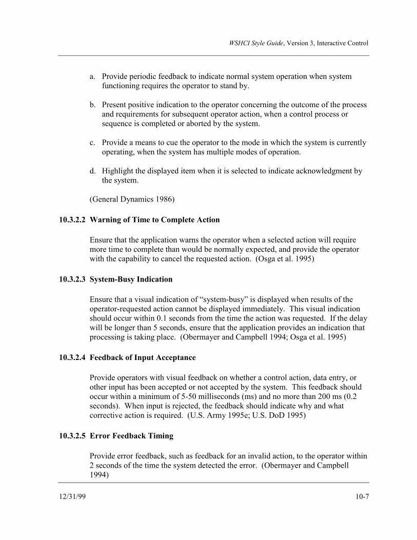
WSHCI Style Guide, Version 3, Interactive Control
12/31/99 10-7
a. Provide periodic feedback to indicate normal system operation when systemfunctioning requires the operator to stand by.
b. Present positive indication to the operator concerning the outcome of the processand requirements for subsequent operator action, when a control process orsequence is completed or aborted by the system.
c. Provide a means to cue the operator to the mode in which the system is currentlyoperating, when the system has multiple modes of operation.
d. Highlight the displayed item when it is selected to indicate acknowledgment bythe system.
(General Dynamics 1986)
10.3.2.2 Warning of Time to Complete Action
Ensure that the application warns the operator when a selected action will requiremore time to complete than would be normally expected, and provide the operatorwith the capability to cancel the requested action. (Osga et al. 1995)
10.3.2.3 System-Busy Indication
Ensure that a visual indication of “system-busy” is displayed when results of theoperator-requested action cannot be displayed immediately. This visual indicationshould occur within 0.1 seconds from the time the action was requested. If the delaywill be longer than 5 seconds, ensure that the application provides an indication thatprocessing is taking place. (Obermayer and Campbell 1994; Osga et al. 1995)
10.3.2.4 Feedback of Input Acceptance
Provide operators with visual feedback on whether a control action, data entry, orother input has been accepted or not accepted by the system. This feedback shouldoccur within a minimum of 5-50 milliseconds (ms) and no more than 200 ms (0.2seconds). When input is rejected, the feedback should indicate why and whatcorrective action is required. (U.S. Army 1995e; U.S. DoD 1995)
10.3.2.5 Error Feedback Timing
Provide error feedback, such as feedback for an invalid action, to the operator within2 seconds of the time the system detected the error. (Obermayer and Campbell1994)

WSHCI Style Guide, Version 3, Interactive Control
10-8 12/31/99
10.3.2.6 Critical Information Availability
Alert the operator when critical information becomes available or changes occur inan inactive or minimized (iconified) window. For windows or applications that aretemporarily frozen for command processing, ensure that the system provides animmediate indication to operators, allowing them to return to automatic updating.Once the display is unfrozen, the system should indicate the information that haschanged. (Obermayer and Campbell 1994)
10.3.2.7 Loss of Critical Signal Input
Provide a visual indication when a tracking system loses the target track or othercritical signal input. This is particularly important for systems that rely on sensorinput and predictive algorithms. (U.S. Army 1995g; WSSG Working Group 1997)
10.3.2.8 Auto-Tracking
Provide a visual indication that auto-tracking is engaged. For systems where theoperator can employ an auto-tracking and/or coasting feature, such as a targettracking and engagement system, ensure that visual indications are evident when thatfeature is engaged.
10.4 CURSOR
10.4.1 General
10.4.1.1 Cursor Pointer Shape
Vary the cursor pointer shape to provide the operator with visual feedback,depending on the functionality being accessed or system mode. See Figure 10.1 foran illustration. (Obermayer and Campbell 1994; U.S. Army 1995e, 1995g)
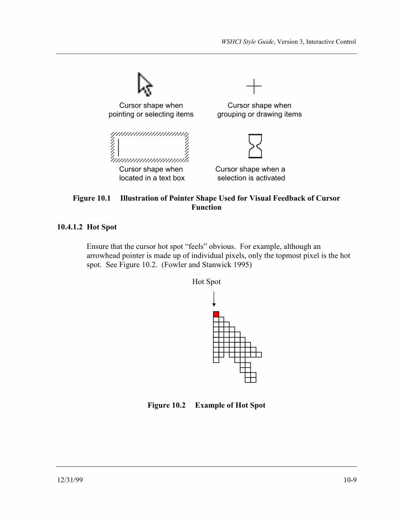
WSHCI Style Guide, Version 3, Interactive Control
12/31/99 10-9
Cursor shape when pointing or selecting items
Cursor shape when a selection is activated
Cursor shape when located in a text box
Cursor shape when grouping or drawing items
Figure 10.1 Illustration of Pointer Shape Used for Visual Feedback of CursorFunction
10.4.1.2 Hot Spot
Ensure that the cursor hot spot “feels” obvious. For example, although anarrowhead pointer is made up of individual pixels, only the topmost pixel is the hotspot. See Figure 10.2. (Fowler and Stanwick 1995)
Hot Spot
Figure 10.2 Example of Hot Spot

WSHCI Style Guide, Version 3, Interactive Control
10-10 12/31/99
10.4.1.3 Cursor Visibility
Ensure that the cursor is constantly visible on the display. Consider the followingdesign principles in maintaining cursor visibility:
a. Ensure that the cursor changes shade, color, or intensity as required to remainvisible while superimposed on menu selections, buttons, icons, or other screenfeatures. (U.S. Army 1995e)
b. Provide the operator with the capability to either enlarge the size of the cursor toaid in locating it against the background, or to bring the cursor to a single homeposition. (Obermayer and Campbell 1994)
c. Ensure that the cursor is constrained from moving off the screen. (Obermayerand Campbell 1994; U.S. Army 1995e)
10.4.1.4 Cursor Movement
Provide the following, where appropriate, for cursor movement:
a. Smooth movement in any X and Y direction.
b. Ability for auto-increment or step function movements for some modes, such asmovement between grids on a map.
(WSSG Working Group 1996)
10.4.2 Redundant Methods for Cursor Movement
Provide a redundant capability to a pointing device for cursor movement or other primarymeans of cursor control. For example, keyboard arrow keys can be a backup method ofcursor control. (U.S. Army 1996b)
10.4.3 Targeting Reticle
10.4.3.1 Composition of Targeting Reticles
Ensure that targeting reticles are composed of both light and dark pixels to ensurevisibility when superimposed on both light and dark backgrounds. (U.S. Army1995g)
WSHCI Style Guide, Version 3, Interactive Control
12/31/99 10-11
10.4.3.2 Targeting Reticle Center
Ensure that targeting reticles include a dot or other visual indication in the center torepresent impact point. This visual indication should not obscure the visibility of thetarget. (U.S. Army 1995g; WSSG Working Group 1996)
10.4.4 Cursor Location
10.4.4.1 Cursors and Multiple Screens
Ensure that the cursor appears in only one screen at a time for systems usingmultiple display screens on separate display devices. (Obermayer and Campbell1994)
10.4.4.2 Discrete and Analog Cursor Location
Ensure that the cursor is appropriately located in the window. For systems usingwindows with discrete cursors, when the window opens, always locate the cursor inthe upper left corner. For systems employing windows with analog cursors, locatethe cursor in the middle of the window when it first opens. (U.S. Army 1996a,1996b)
10.4.4.3 Location of Cursor for Option Selection
Design menus so the cursor is automatically placed on the most likely option to beselected. If there is no likely option, ensure that the cursor is automatically placed atthe top of the option list. (Site visit to TARDEC 1996; WSSG Working Group1996)
10.5 DIRECT MANIPULATION
Direct manipulation is an interaction technique that allows the user to control computerinteraction by acting directly on objects such as windows, buttons, or icons on-screen. Whenusing a GUI, these objects are organized using metaphors and visual representations of real-life objects from the user's task environment. Using a computer, the user interacts directlywith a graphical representation of a physical object to complete a task and has the sensation ofworking directly with or manipulating these objects.
Direct manipulation user interfaces contain the following three characteristics:
• Continuous representation of the object of interest to the user
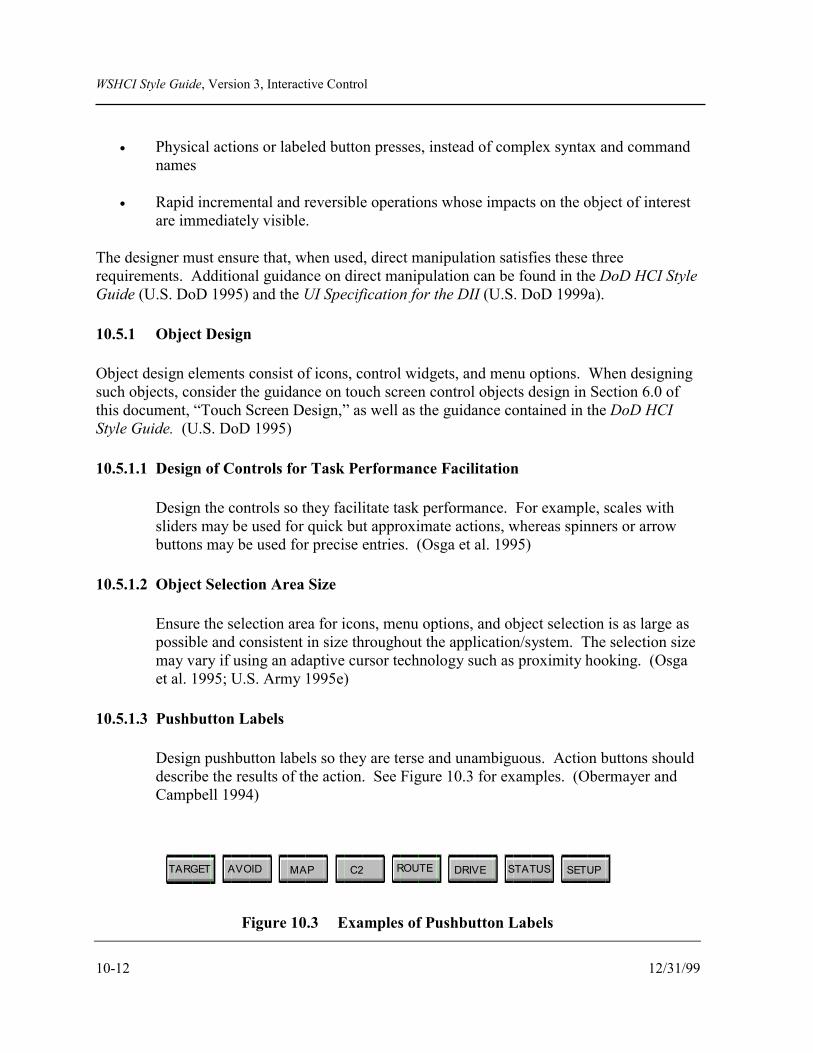
WSHCI Style Guide, Version 3, Interactive Control
10-12 12/31/99
• Physical actions or labeled button presses, instead of complex syntax and commandnames
• Rapid incremental and reversible operations whose impacts on the object of interestare immediately visible.
The designer must ensure that, when used, direct manipulation satisfies these threerequirements. Additional guidance on direct manipulation can be found in the DoD HCI StyleGuide (U.S. DoD 1995) and the UI Specification for the DII (U.S. DoD 1999a).
10.5.1 Object Design
Object design elements consist of icons, control widgets, and menu options. When designingsuch objects, consider the guidance on touch screen control objects design in Section 6.0 ofthis document, “Touch Screen Design,” as well as the guidance contained in the DoD HCIStyle Guide. (U.S. DoD 1995)
10.5.1.1 Design of Controls for Task Performance Facilitation
Design the controls so they facilitate task performance. For example, scales withsliders may be used for quick but approximate actions, whereas spinners or arrowbuttons may be used for precise entries. (Osga et al. 1995)
10.5.1.2 Object Selection Area Size
Ensure the selection area for icons, menu options, and object selection is as large aspossible and consistent in size throughout the application/system. The selection sizemay vary if using an adaptive cursor technology such as proximity hooking. (Osgaet al. 1995; U.S. Army 1995e)
10.5.1.3 Pushbutton Labels
Design pushbutton labels so they are terse and unambiguous. Action buttons shoulddescribe the results of the action. See Figure 10.3 for examples. (Obermayer andCampbell 1994)
TARGET AVOID MAP C2 ROUTE DRIVE STATUS SETUP
Figure 10.3 Examples of Pushbutton Labels
WSHCI Style Guide, Version 3, Interactive Control
12/31/99 10-13
10.5.1.4 Defaulting to Destructive Options
Do not default to an option that represents a potential destructive action. (Osga et al.1995)
10.5.1.5 Indication of Functional or Nonfunctional Options
Ensure that functional or enabled buttons or options are visually distinct fromdisabled or nonfunctional options and buttons. For example, nonfunctional optionscould be grayed out. (U.S. Army 1995d)
10.5.2 Option Selection
10.5.2.1 Location of Selection Points
Design RT/NRT display screens, where possible, so that selection options arelocated close to one another. This will reduce the time required to reach and selectobjects per Fitts Law. (Card et al. 1983)
10.5.2.2 Proximity Selection of Objects and Options
Consider designing the system so objects and symbols are selected throughproximity of the pointer/cursor rather than requiring the pointer to be placed on theobject. When using proximity highlighting, ensure that the highlighted symbol isdifferent than the selected symbol. (Osga et al. 1995; WSSG Working Group 1997)
10.5.2.3 Option Selection Sensitivity to Vibration
Ensure that, when designing option selection using a pointing device, the selectionmethod is not sensitive to the inherent vibration in some RT/NRT systems, thusavoiding inadvertently selecting an object or initiating an action. (U.S. Army 1995e)
10.5.2.4 Movement to Foreground of Selected Object
Ensure that, when an object or icon is selected, i.e., receives focus or is hooked, itmoves to the foreground to guarantee that it is unobscured. (Obermayer andCampbell 1994)
WSHCI Style Guide, Version 3, Interactive Control
10-14 12/31/99
10.5.2.5 Indication of Action Taken
Provide a positive visual indication to the operator once an action is taken with asymbol or object, such as having the object remain highlighted. (Obermayer andCampbell 1994)
10.5.3 Click and Point Versus Click and Drag
Consider, when designing direct manipulation interfaces, that a click-and-drag interface suchas that used to scroll a window takes more time when compared to point and click. ForRT/NRT system functions where response time is critical, using point and click to pagethrough multiple windows/pages may be preferred to scrolling a window. (MacKenzie 1994;Steinberg et al. 1994; U.S. DoD 1995)
10.6 MENU DESIGN
More detailed guidelines for designing menus are included in the DoD HCI Style Guide (U.S.DoD 1995).
10.6.1 Format of Menus
10.6.1.1 Organization of Menus
Consider organizing menus around subsystems or operational modes, with eachsubsystem or mode functionality accessed from a top-level menu option. (U.S.Army 1996b)
10.6.1.2 Multipage Menu Design
Design multipage menus so a operator does not have to scroll a display to access allthe options. If options extend beyond the immediate display, break up the optionsand allow access through paging, cascading, or pop-up boxes. Pop-up boxes shouldnot overlap critical information such as alerts messages or system status areas. (Sitevisit to General Dynamics Land Systems Division 1996; WSSG Working Group1996)
10.6.1.3 Number of Menu Options
Design menus so that options per menu do not exceed 10, and preferably no morethan 3 to 5. (Obermayer and Campbell 1994; U.S. Army 1995g)

WSHCI Style Guide, Version 3, Interactive Control
12/31/99 10-15
10.6.1.4 Indication of Option Selection
Highlight the option when the cursor rests on a menu option in an RT/NRT system.See Figure 10.4. (U.S. Army 1995e)
Figure 10.4 Illustration of How a Menu Option Should be Highlighted
10.6.1.5 Indication of Unavailable Menu Options
Visually indicate inactive or unavailable options by dimming or graying out theoption. If appropriate, hide unavailable options. (U.S. Army 1995a, 1995b, 1995e;WSSG Working Group 1996)
10.6.1.6 Organization of Options
Organize menu options as follows:
a. Group and arrange options logically within a group according to frequency ofuse, with the most frequently used options at the top of the menu structure.(Obermayer and Campbell 1994; U.S. Army 1995e)
b. Organize options alphabetically or numerically, if there is no apparentorganization based on logical groups or frequency of use. (Obermayer andCampbell 1994)
c. Organize similar options on different menus consistently. (Obermayer andCampbell 1994)

WSHCI Style Guide, Version 3, Interactive Control
10-16 12/31/99
10.6.1.7 Location of Infrequently Used or Destructive Options
Locate less frequently used or potentially destructive options at the end of a menustructure. (Obermayer and Campbell 1994; U.S. Army 1995e)
10.6.2 Return to the Top or Next Level
Provide the capability for the operator to cancel out of any menu and return to the top level, orto the previous level, with one action. (U.S. Army 1996b; WSSG Working Group 1996)
10.6.3 Visual Distinction Between Selected and Non-Selected Options
Provide a visual distinction between selected and non-selected menu options, for example,highlighting or underlining selected options. (General Dynamics 1986)
10.6.4 Menu Navigation
10.6.4.1 Indication of Submenus
Provide a visual indication when a menu option will take the operator to a submenu.For example, use an arrowhead to indicate a cascading menu or three ellipses toindicate a pop-up menu. See Figure 10.5 for an illustration. (U.S. Army 1995d)
10.6.4.2 Hierarchical Location Indicators
Ensure that the system provides a constant indication of the operator’s current placewithin a hierarchical task or operational sequence, as well as provides navigationalaids to help operators identify where they are in a hierarchical menu structure. SeeFigure 10.6 for an illustration. (General Dynamics 1986; Site visit to GeneralDynamics Land Systems Division 1996)

WSHCI Style Guide, Version 3, Interactive Control
12/31/99 10-17
Figure 10.5 Illustration of Visual Indication of Submenu

WSHCI Style Guide, Version 3, Interactive Control
10-18
TGTACQ
HITAV OID MAP
F1
F2
F3
F4
BRT
Weapons Con(S
F
L
R
Screen Na
Figure 10.6 Illustration of
Weapons Control
Sensor SelectionFLIRLaserRadar
Ammo TypeArtilleryMortarRocket
Target TypePersonnelTanksWheeled Vehicles
Menu Map
12/31/99
C2 ROUTEPLAN DRIV E SYS
STAT SETUP
F5
F6
F7
F8
CNTRST
trol: Sensor Selectiontep 2 of 4)
FLIR
Laser
Radar
vigation Indication
Two Types of Menu Navigation Aids
WSHCI Style Guide, Version 3, Interactive Control
12/31/99 10-19
10.6.4.3 Menu Control Using Keyboards
Provide the following where keyboards can be used to control menu selection:
a. If only the menu bar is active, ensure that the right keyboard arrow moves theoption selection cursor to the next option at the right, and the left arrow moves itto the left. If the cursor is at the end of a menu, movement of the cursor shouldwrap to the beginning of the menu bar.
b. Ensure that the down arrow causes the menu option list to drop down and thefirst option to be highlighted.
c. If the menu option list is already dropped, ensure that the down arrow moves thecursor to advance to the next item on the list. If the cursor is located at the endof the list, it should then wrap to the top.
(WSSG Working Group 1996)

WSHCI Style Guide, Version 3, Interactive Control
10-20 12/31/99
This page intentionally left blank.

WSHCI Style Guide, Version 3, Screen Design
12/31/99 11-1
11.0 SCREEN DESIGN
11.1 GENERAL
Screen design includes the arrangement and presentation of information displayed on anoutput device. Screen design requirements are unique for each system and subdomain ofsystems—ground, aviation, missile, soldier, and munition—depending on the system’sprimary function. The designer needs to understand the primary function of the system beingdeveloped to provide an effective screen design. For RT/NRT systems, the designer needs tokeep in mind that screen design must support the operator’s need to make immediatedecisions regarding the displayed information, and that the display device may be small, aswell as subject to vibration, variable lighting, and extreme environments.
The designer should also incorporate the following general principles of Human FactorsEngineering (HFE) into the screen design, regardless of the system function:
• Guide the organization of information by these basic principles of perception:
- Proximity. The human perception system tries to organize objects into groups ifthey are near each other in space.
- Similarity. Objects are perceived as a group or set if they visually sharecommon properties, such as size, color, orientation in space, or brightness.
- Closure. The human visual perception system tries to complete the figure andestablish meaningful wholes. The incomplete object or symbol may be seen ascomplete or whole.
- Balance. Humans prefer stability in the perceived visual environment. Thepresentation of materials at right angles and in vertical or horizontal groupings iseasier to look at than curved or angled visual images.
• Improve user performance by implementing the following screen features:
- Simple, well-organized presentation
- Orderly, clutter-free appearance
- Information present in expected locations
- Plain, simple language
- Simple way to move through the system
- Clear representation of interrelationships.

WSHCI Style Guide, Version 3, Screen Design
11-2 12/31/99
• Design display formats to group data items on the basis of some logical principle,considering trade-offs derived from task analysis.
• Design screens to minimize eye and cursor movement requirements within theoverall design. The goal to minimize eye and cursor movement must be consideredwithin general task considerations, with logical trade-offs taken into account. (U.S.DoD 1995)
• Display only the information that is essential to mission performance.
• Display information only as accurately as the operator's decisions and controlactions require. For example, do not provide numerical information to decimalplaces beyond which the operator needs to make a decision.
• Present data in the most direct, simple, understandable, and usable form possible.
• Arrange information on displays so the operator can locate and identify them easily,without unnecessary searching.
Use the following guidelines to develop the design of screens for RT/NRT systems.
11.1.1 Grouping by Proximity or Other Cues
Group elements and data by proximity or other cues such as color, where integration of screenelements and data are required. Where multifunction displays are used, consider the locationof the multifunction keys in designing the screens. (Andre and Wickens 1989; WSSGWorking Group 1996)
11.1.2 Presentation of Alerting Information
Present alerts for noncritical information in the operator’s peripheral field of vision to reducefoveal information load, but ensure that it is still within the primary visual field. The fovea isthe portion of the retina used for acute vision. (U.S. DoD 1981; Walrath 1994; WSSGWorking Group 1996)
11.1.3 Key Features Protection
Ensure that key display features, such as main menu bars and critical warnings or othermessages, are not movable or resizable and that they cannot be covered by other windows.(Osga et al. 1995)

WSHCI Style Guide, Version 3, Screen Design
12/31/99 11-3
11.1.4 Location of Most Important Information
In general, design screens with the most important task information located in the upper leftcorner of the screen, unless another arrangement is more operationally logical. Set apartcritical information visually from other information. (Osga et al. 1995)
11.1.5 Status Message Area
Provide a dedicated status message area to be located consistently throughout the application.The recommended location is the bottom of the display. Do not use this status message areafor critical warnings. (U.S. Army 1995g; WSSG Working Group 1996)
11.1.6 Weapon and Sensor Systems Orientation
Provide an indication of the orientation of the weapon or sensor, for weapon and sensorsystems where the direction of the weapon or sensor can vary. Figure 11.1 provides anillustration. (U.S. Army 1995g; WSSG Working Group 1996)
TGTACQ
HITAVOID MAP C2 ROUTE
PLAN DRIVE SYSSTAT SETUP
F1
F2
F3
F4
F5
F6
F7
F8
BRT CNTRST
N
Figure 11.1 Illustration of Weapon/Sensor Orientation

WSHCI Style Guide, Version 3, Screen Design
11-4 12/31/99
11.1.7 Multipage Information Display
Display the total number of pages and the current page number, when more than one page ofinformation is provided, e.g., Page 2 of 3. (U.S. Army 1996b)
11.1.8 Consistent Appearance for Similar Controls and Screen Elements
Ensure that controls and other screen elements with the same function have the sameappearance. (Osga et al. 1995)
11.1.9 Screen Elements Identification by Appearance
Clearly identify controls and other screen elements by their appearance. See Figure 11.2 forexamples. (Osga et al. 1995)
Pop-up Menu
OPTION ...
OPTION Option 1
Option 2
Option 3
Cascading Menu
Pushbuttons
Option 1
Option 2Option 3
OK Cancel
Figure 11.2 Examples of Visually Identifiable Controls and Screen Elements
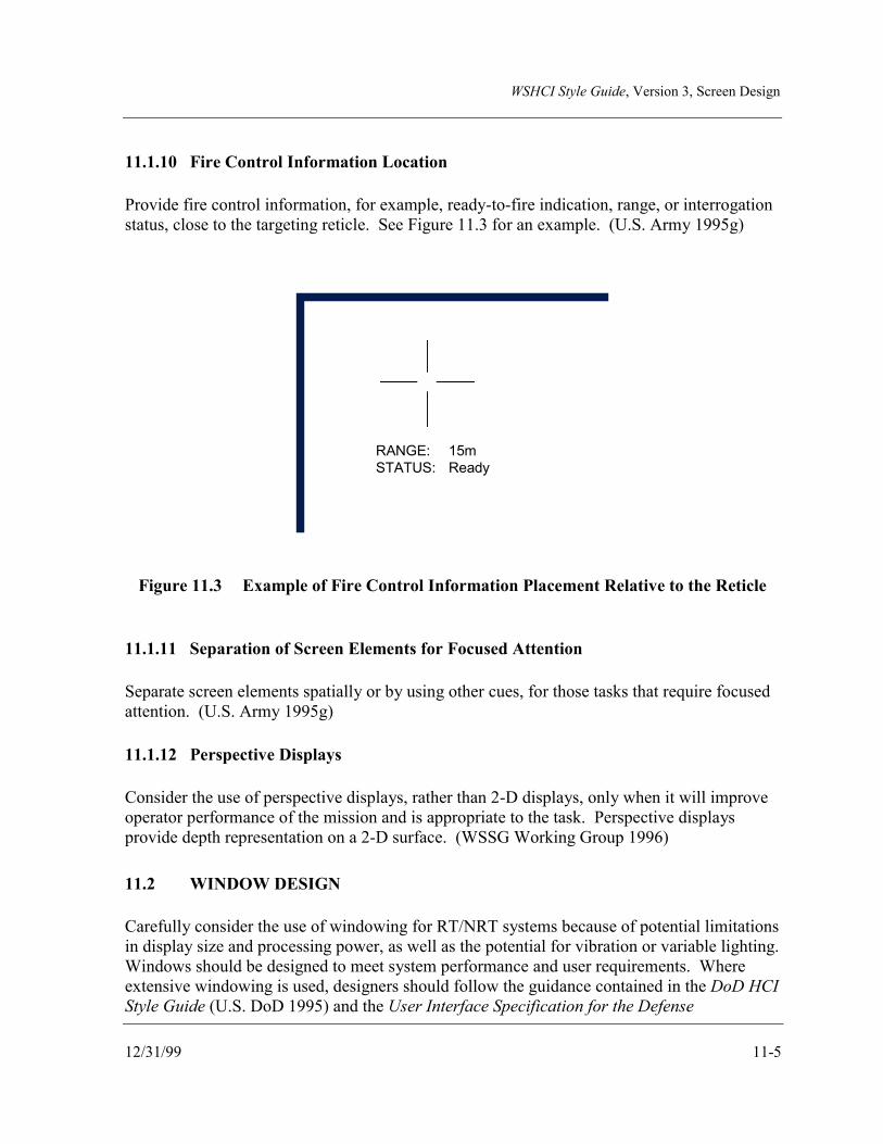
WSHCI Style Guide, Version 3, Screen Design
12/31/99 11-5
11.1.10 Fire Control Information Location
Provide fire control information, for example, ready-to-fire indication, range, or interrogationstatus, close to the targeting reticle. See Figure 11.3 for an example. (U.S. Army 1995g)
RANGE: 15mSTATUS: Ready
Figure 11.3 Example of Fire Control Information Placement Relative to the Reticle
11.1.11 Separation of Screen Elements for Focused Attention
Separate screen elements spatially or by using other cues, for those tasks that require focusedattention. (U.S. Army 1995g)
11.1.12 Perspective Displays
Consider the use of perspective displays, rather than 2-D displays, only when it will improveoperator performance of the mission and is appropriate to the task. Perspective displaysprovide depth representation on a 2-D surface. (WSSG Working Group 1996)
11.2 WINDOW DESIGN
Carefully consider the use of windowing for RT/NRT systems because of potential limitationsin display size and processing power, as well as the potential for vibration or variable lighting.Windows should be designed to meet system performance and user requirements. Whereextensive windowing is used, designers should follow the guidance contained in the DoD HCIStyle Guide (U.S. DoD 1995) and the User Interface Specification for the Defense

WSHCI Style Guide, Version 3, Screen Design
11-6 12/31/99
Information Infrastructure (U.S. DoD 1999a), unless there is a compelling operational reasonfor these documents to not be applicable.
11.2.1 Fixed Window Design
Unless there is a compelling operational requirement, design windows for RT/NRT systemsso that they are fixed regions and not resizable, movable, or multilayered so that they requireforward and backward movement. (U.S. Army 1996e)
11.2.2 Window Appearance
11.2.2.1 Identification of Window Controls
Ensure that window controls are identifiable based solely on their appearance. Allcontrols with the same function should have the identical appearance. (Obermayerand Campbell 1994)
11.2.2.2 Window Titles
Ensure that windows have descriptive titles centered at the top. (U.S. Army 1996a)
11.2.2.3 Consistent Design of Windows Performing the Same Tasks
Design windows performing the same basic task to look and behave in the sameway. (Obermayer and Campbell 1994)
11.2.3 Multifunction Key Context Definition
Ensure that the multifunction key that has opened a window retains its visual indication ofactivation, e.g., highlighted, to provide window context to the operator. (U.S. Army 1996a)
11.2.4 Window Control
11.2.4.1 Maintenance of Overwritten Background Information
Ensure that, when a window is opened on top of existing information on a screen,the existing or “background” information is not lost, but saved and redisplayed whenthe top window is moved or closed. (U.S. Army 1994)

WSHCI Style Guide, Version 3, Screen Design
12/31/99 11-7
11.2.4.2 Closing a Window and Associated Subwindows
Ensure that closing a primary window (parent) causes all subwindows (children)associated with that window to close. (U.S. Army 1994)
11.2.4.3 Location of Window Opened with Multifunction Key
When opening a window using a multifunction key, design this feature such that thewindow appears close to the multifunction key that opened it. See Figure 11.4.(U.S. Army 1996a)
TGTACQ
HITAVOID MAP C2 ROUTE
PLAN DRIVE SYSSTAT SETUP
Fire Control
F2
F3
F4
F5
F6
F7
F8
BRT CNTRST
Fire Control
Figure 11.4 Illustration of Window Location when Opened by a Multifunction Key
11.2.4.4 Covering (Occluding) of Critical Screen Information
Ensure that pull-down or pop-up menus, as well as windows, do not occlude criticalscreen information, such as message alert areas. (WSSG Working Group 1996)

WSHCI Style Guide, Version 3, Screen Design
11-8 12/31/99
11.2.4.5 Context Sensitive Windowing Hierarchy
Provide the user with a navigational route through the window/menu hierarchy,whereby the flow of each thread through the hierarchical structure is a logicalsequence of end-to-end processes accomplishing a real-world task. These processesare created from sub-tasks or elemental steps that, when performed sequentially instepwise fashion, complete a task sequentially from beginning to end. The idealstructure of the hierarchy would be where only a single window/menu is needed forthe completion of a task or sub-task. (WSSG Working Group 1996)
11.2.5 Window Dialog
11.2.5.1 Single Selection Pop-up Windows
Consider using single selection pop-up windows when the operator must select onlyone option from a list. Selecting the option through a single activation control suchas touch button, enter key, or other pointing device will cause the option to beimplemented and the window to close. (U.S. Army 1996a) See Figure 11.5 for anexample.
The design of single selection windows should ensure that:
a. the current or default selection is highlighted when the window opens. SeeFigure 11.6 for an example. (U.S. Army 1996a)
b. the selection button, if a soft key, remains highlighted until its associatedwindow disappears. (U.S. Army 1996e)

WSHCI Style Guide, Version 3, Screen Design
12/31/99 11-9
TGTACQ
HITAVOID MAP C2 ROUTE
PLAN DRIVE SYSSTAT SETUP
F1
F2
F3
F4
F5
F6
F7
F8
BRT CNTRST
SENSOR SELECT
CancelOK
Clicking here selects Laser and causes window to close
LLTV
FLIR
LASER
Figure 11.5 Example of a Single Selection Pop-Up Window
TGTACQ
HITAVOID MAP C2 ROUTE
PLAN DRIVE SYSSTAT SETUP
F1
F2
F3
F4
F5
F6
F7
F8
BRT CNTRST
Default
SENSOR SELECT
CancelOK
LLTV
FLIR
LASER
Figure 11.6 Example of Current or Default Selection on Single Selection Pop-UpWindows

WSHCI Style Guide, Version 3, Screen Design
11-10 12/31/99
11.2.5.2 Multiple Selection Pop-Up Window
Provide a multiple-selection pop-up window, when the operator needs to select morethan one option from a list. See Figure 11.7 for an example. (U.S. Army 1996a)
TGTACQ
HITAVOID MAP C2 ROUTE
PLAN DRIVE SYSSTAT SETUP
F1
F2
F3
F4
F5
F6
F7
F8
BRT CNTRST
SENSOR SELECT
CancelOK
TwoSelections
LLTV
FLIR
LASER
OTHER
X
X
Figure 11.7 Example of a Multiple-Selection Pop-Up Window
Multiple selection pop-up windows should be designed so that:
a. at least the default or the previously selected option is highlighted when amultiple-selection pop-up window opens. The operator can then highlight,thereby select, additional options. Activation can be performed through an“OK” or “DONE” button. (U.S. Army 1996a)
b. check boxes, if used, are placed to the left of each option. (U.S. Army 1996e)
c. for check boxes, an X or check in the box indicates it is selected. (U.S. Army1996e)
d. OK and Cancel Buttons are at the bottom of the window, with OK being on theleft and Cancel on the right. (U.S. Army 1996e)
e. OK indicates acceptance of the options and closes the window. (U.S. Army1996e)

WSHCI Style Guide, Version 3, Screen Design
12/31/99 11-11
11.2.5.3 Window Input Focus
Ensure that the default window input focus is “explicit.” Windows have input focuswhen they are active, meaning they are ready to accept command or data input.There are two types of input focus models for windows: explicit and implicit.Explicit is where the user takes an overt action to move input focus, such asactivating a trackball control when the cursor has been moved into the window.Implicit focus is when the window becomes active as soon as the cursor is movedinto the window. (U.S. DoD 1999a) When a window has been opened that requiresthe operator to make a selection, it should have sole input focus, though informationbehind it may still be visible. (U.S. Army 1996e)
11.2.5.4 Indicating Window Input Focus
Visually indicate input focus by a change in either the window frame, if it has one,or in the window title. See Figure 11.8 for an example. (U.S. Army 1995d)
TGTACQ
HITAVOID MAP C2 ROUTE
PLAN DRIVE SYSSTAT SETUP
F1
F2
F3
F4
F5
F6
F7
F8
BRT CNTRST
WINDOW 2
WINDOW 1
Window with Input Focus
Inactive Window
Figure 11.8 Illustration of How To Visually Indicate Input Focus

WSHCI Style Guide, Version 3, Screen Design
11-12 12/31/99
11.2.5.5 Include All Required Information Within a Window
Where possible to maintain an efficient and effective user interface, include allinformation necessary to complete the task within a window. (Osga et al. 1995)
11.2.6 Multiple Layers of Windows
Design an RT/NRT system that uses multiple layers of windows using the followingprinciples. Ensure that:
a. non-critical windows cannot be moved or resized such that they obscure criticalscreen areas, e.g., message alert areas or other critical windows.
b. windows containing critical information cannot be closed without confirmation bythe user.
c. critical windows cannot be moved off the screen.
d. critical windows move to the top (or front), or an indication is provided to theoperator when critical events occur with the information being displayed orcontrolled from that window. Ensure that this does not disrupt on-going user tasks.
e. users can display an open window map that indicates which windows are currentlyopen, and that allows the user to navigate to any open window.
f. return to the home screen is performed through one operator action, though thisaction should require confirmation by the user.
g. windows have a default location for appearance on the screen.
11.2.7 Dialog Box Design
11.2.7.1 General Design
Design dialog boxes so that they:
a. follow the guidance in found in the DoD HCI Style Guide (U.S. DoD 1995).
b. have input focus.
c. contain all selectable functions for that dialog.
WSHCI Style Guide, Version 3, Screen Design
12/31/99 11-13
d. are centered in primary area of user attention on the screen.
e. highlight the default option with the cursor.
f. include OK and Cancel buttons, with the OK being on the left.
(U.S. Army 1996e)
11.2.7.2 Dialog Box Default
When appropriate for the operational task, include a default pushbutton in dialogboxes that represents the most frequently selected option or that is most appropriatefor the current situation. (Osga et al. 1995)
11.3 TEXT AND DATA PRESENTATION
11.3.1 Information Requirements for the Content of Displays
11.3.1.1 Content
Strictly limit the information displayed to the operator operating an RT/NRT systemto that which is necessary for performing specific actions, monitoring a situation, ormaking decisions or assessments. (General Dynamics 1986)
11.3.1.2 Precision
Display information only to the level of precision that is operationally meaningfuland useful to the operator. For example, if the operator uses distance data to thenearest kilometer, do not provide data down to the meter. (General Dynamics 1986)
11.3.1.3 Format
Present information to the operator in a directly usable form to minimize therequirements for actions such as transposing, computing, interpolating, andconverting units. (General Dynamics 1986)
11.3.1.4 Combining Operator and Maintainer Information
Do not combine operator and maintainer information in a single display unless theinformation in terms of content and format lends itself to being combined. (GeneralDynamics 1986)
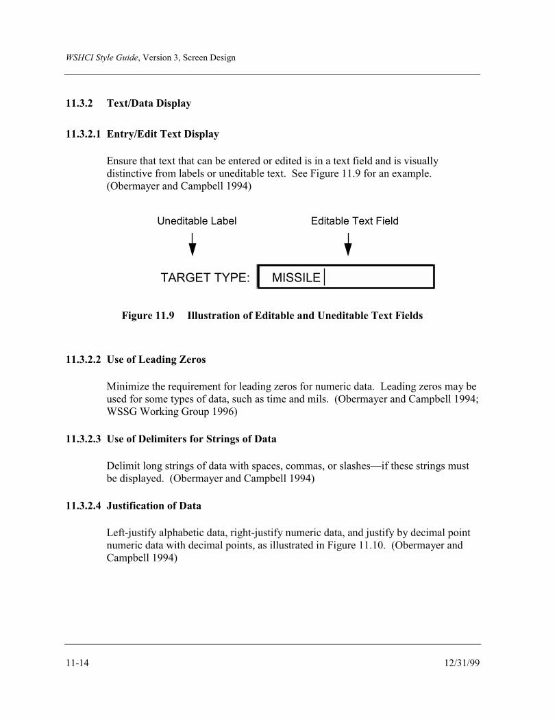
WSHCI Style Guide, Version 3, Screen Design
11-14 12/31/99
11.3.2 Text/Data Display
11.3.2.1 Entry/Edit Text Display
Ensure that text that can be entered or edited is in a text field and is visuallydistinctive from labels or uneditable text. See Figure 11.9 for an example.(Obermayer and Campbell 1994)
TARGET TYPE: MISSILE
Uneditable Label Editable Text Field
Figure 11.9 Illustration of Editable and Uneditable Text Fields
11.3.2.2 Use of Leading Zeros
Minimize the requirement for leading zeros for numeric data. Leading zeros may beused for some types of data, such as time and mils. (Obermayer and Campbell 1994;WSSG Working Group 1996)
11.3.2.3 Use of Delimiters for Strings of Data
Delimit long strings of data with spaces, commas, or slashes—if these strings mustbe displayed. (Obermayer and Campbell 1994)
11.3.2.4 Justification of Data
Left-justify alphabetic data, right-justify numeric data, and justify by decimal pointnumeric data with decimal points, as illustrated in Figure 11.10. (Obermayer andCampbell 1994)

WSHCI Style Guide, Version 3, Screen Design
12/31/99 11-15
Poor Good
Washington DC Washington DC
Cars Cars
People People
400 400
4210 4210
39111 39111
1.5 1.500
10.36 10.360
1.365 1.365
Figure 11.10 Illustration of How Data Should Be Justified
11.3.2.5 Use of Delimiters for Rows and Columns
Insert a blank line, if the display contains many rows and columns, after every thirdto fifth row, and insert three spaces between every column to facilitate scanning byoperators. (Obermayer and Campbell 1994)
11.3.2.6 Grouping Columnar Data
Indicate grouping of data within a column by blank space between the columns or bya separator line. (Obermayer and Campbell 1994)
11.3.2.7 Separation of Columns
Clearly separate each column of data from other columns by a minimum of threespaces. (Obermayer and Campbell 1994)
11.3.2.8 Headings for Columns and Rows
Ensure that data presented in columnar or tabular format have a heading describingthe type of data. (Obermayer and Campbell 1994)

WSHCI Style Guide, Version 3, Screen Design
11-16 12/31/99
11.3.2.9 Presentation of Likelihood of Outcome Information
Display items, when presenting information in terms of likelihood of an outcome,either in rank-order or present only the highest likely item. Do not include theabsolute likelihood ratings. See Figure 11.11 for an example. (Dunkelberger 1995)
This Not ThisLikelihood of Kill 90%
Order of Possible SCUDTarget Types SAM
Likelihood of Kill 90.105%
Possible Target Types SAM (40.6%)SCUD (59.4%)
Figure 11.11 Example of How to Present Likelihood of Outcome Data
11.3.3 Text/Data Entry
11.3.3.1 Autofilling of Critical Messages
Design all critical messages, where possible, so that as many fields as possible areautofilled from on-board sensors, databases, or other means, to reduce the need fordata entry by the operator. Provide the operator with the ability to accept and editautofilled information. (Site visit to TARDEC 1996; WSSG Working Group 1996)
11.3.3.2 Cues for of Data
Provide the operator a cue to indicate when a field has been filled, if the system usesautocompletion to automatically complete data entry based on partial operator input.(Gould et al. 1990)

WSHCI Style Guide, Version 3, Screen Design
12/31/99 11-17
11.3.3.3 Use of Insert Mode
Use the insert mode as the default rather than the overwrite (replace) mode as thedata entry default. If the operator has the capability to change from insert tooverwrite mode, ensure that the current mode is indicated. (Obermayer andCampbell 1994; WSSG Working Group 1996)
11.4 GRAPHICS
11.4.1 Map Graphics
In general, map graphics for RT/NRT systems should conform to the guidance contained inthe appropriate sections of the DoD HCI Style Guide (U.S. DoD 1995). Additional guidancefor RT/NRT systems is as follows.
11.4.1.1 Scrolling
Ensure that maps allow the user to scroll horizontally (left to right), vertically (top tobottom), and diagonally. Where feasible, provide the capability for the map to scrollautomatically to follow vehicle or operator progress. (U.S. Army 1995f; WSSGWorking Group 1996)
Other scrolling design considerations include the following:
a. Provide an indication to the operator of critical information being displayed inan area of a scrolled map window that is not currently being displayed on thescreen. (WSSG Working Group 1996)
b. Consider designing object movement such that, when a force transducer,pointing device, or equivalent of a joystick is causing movement (i.e., of amap), graphics viewing is moved either proportional to force or time inposition. For example, if a force transducer is pressed harder or held down in aposition to cause viewing of a map from lower to upper areas, the view ratewould move from one viewing area per second to three viewing areas persecond. (WSSG Working Group 1996)
11.4.1.2 Panning
Provide the operator with the capability to view all areas beyond a display frame byproviding a fixed “window” or frame that can be panned in any direction. Considerthe following:

WSHCI Style Guide, Version 3, Screen Design
11-18 12/31/99
a. Select the panning capability, either discrete or continuous, based on the crewmember’s specific task requirements. Continuous panning capability ispreferable to discrete for most tasks, but discrete may be used if the crewmember cannot pan smoothly or needs to rapidly “jump” to specific locations orareas of interest.
b. Ensure that display framing is consistently implemented for panning operationsthroughout the interface design, so the operator can either conceive the displayframe as a window moving over a fixed array of data or conceive data as movingbehind a fixed display frame.
c. During panning operations, provide some graphic indication of the currentposition relative to the overall display.
d. During panning operations, provide a means for rapidly returning to the origin.
e. Ensure that framing functions perform integrally so that panning and/or zoomingwill affect all displayed data in the same way.
f. When a zooming or panning option is provided, provide a method that allows theoperator to select a given position on the display page to become the center forthe zooming or panning operation.
g. If graphical display pages can be customized through options such as panning,zooming, and decluttering, provide a method for the operator to return to adefault display configuration.
(Smith and Mosier 1986; U.S. DoD 1995; WSSG Working Group 1997)
11.4.1.3 Zooming
Design map displays for real-time systems so there will be a compensating shift inthe size of the symbology, labels, and other map features when users zoom thecoverage area. When zooming out, this would include an aggregation of symbols toreduce visual clutter. (Obermayer and Campbell 1994; WSSG Working Group1997)
11.4.1.4 Modification of Map Overlays
Ensure that operators can modify the contents of a map overlay by adding, deleting,editing, or relocating labels and symbols. (Obermayer and Campbell 1994)
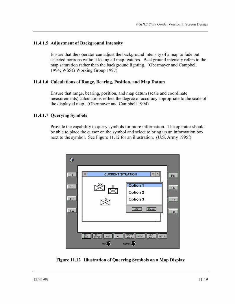
WSHCI Style Guide, Version 3, Screen Design
12/31/99 11-19
11.4.1.5 Adjustment of Background Intensity
Ensure that the operator can adjust the background intensity of a map to fade outselected portions without losing all map features. Background intensity refers to themap saturation rather than the background lighting. (Obermayer and Campbell1994; WSSG Working Group 1997)
11.4.1.6 Calculations of Range, Bearing, Position, and Map Datum
Ensure that range, bearing, position, and map datum (scale and coordinatemeasurements) calculations reflect the degree of accuracy appropriate to the scale ofthe displayed map. (Obermayer and Campbell 1994)
11.4.1.7 Querying Symbols
Provide the capability to query symbols for more information. The operator shouldbe able to place the cursor on the symbol and select to bring up an information boxnext to the symbol. See Figure 11.12 for an illustration. (U.S. Army 1995f)
TGTACQ
HITAVOID MAP C2 ROUTE
PLAN DRIVE SYSSTAT SETUP
F1
F2
F3
F4
F5
F6
F7
F8
BRT CNTRST
CURRENT SITUATION
Option 1
Option 2
Option 3
OK Cancel
xx
x
Figure 11.12 Illustration of Querying Symbols on a Map Display

WSHCI Style Guide, Version 3, Screen Design
11-20 12/31/99
11.4.1.8 Map Graphic and Overlay Control Functionality
Provide the following control functionality for map graphics and overlays:
a. Scale - Allow either zooming or stepped scaling of maps and overlays.
b. Orient - Allow orientation of a map and overlay to either north or systemprimary operational axis, e.g., vehicle heading, azimuth of fire, etc. Maplabeling should remain oriented to the user position.
c. Home - Allow a return of the map or overlay view so that it is centered on adesignated home position, such as the user’s own position.
d. Declutter - Allow declutter of noncritical information off the map or overlaygraphic.
(U.S. Army 1995f; U.S. Army 1996a)
11.4.1.9 Map Symbology
Design map symbology in accordance with the standards cited in the Joint TechnicalArchitecture - Army (U.S. Army 1999), as well as Operational Terms and Graphics,U.S. Army Field Manual 101-5-1 (U.S. Army 1980). See Section 12.6,“Symbology,” for more information on symbology. (U.S. Army 1995f)
11.4.1.10 Shades of Gray (Gray Scale)
Select steps in a gray scale that produce shades of gray resulting in just noticeabledifferences that are spaced at perceptually equal intervals (rather than equal steps ofluminance or gamma-corrected CRT voltage). There is no universally acceptednumber of shades of gray for the application. The number of gray shades that shouldbe used for an application is based on the task and the brightness range in the image.It has been estimated that about 30 gray levels can be visually distinctive on a CRTor photographic print, while only 8 levels can be reliably produced on color-matrixdisplays. Data from experiments with human observers indicate that approximately200 just noticeable differences can be seen for targets on a highly luminoussurround, indicating that eight bits or 256 levels may be the usable maximumnumber of steps for a gray scale. The maximum number of shades of gray can beachieved with a background of moderate luminance, when compared with a black orwhite background. (Carter 1993, 1997)
WSHCI Style Guide, Version 3, Screen Design
12/31/99 11-21
11.4.2 Presentation Graphics
Design presentation graphics in accordance with the appropriate section of the DoD HCI StyleGuide (U.S. DoD 1995).

WSHCI Style Guide, Version 3, Screen Design
11-22 12/31/99
This page intentionally left blank.
WSHCI Style Guide, Version 3, Coding
12/31/99 12-1
12.0 Coding
Coding information on a display, as any design attribute for RT/NRT systems, requires thatthe designer be aware of HCI design constraints. These constraints include the need for quickrecognition of the coded information, as well as the potential impact of vibration and variableambient lighting.
12.1 GENERAL
12.1.1 Coding of Time-Critical Information
Use bolding, brightness, shape, color, or other coding techniques to focus the operator’sattention on time-critical information and changes in the state of the system. (Obermayer andCampbell 1994; General Dynamics 1986; Osga et al. 1995)
12.1.2 Code Consistency and Meaningfulness
Use consistent, meaningful codes that do not reduce legibility or increase transmission time.(General Dynamics 1986)
12.2 BRIGHTNESS CODING
12.2.1 Use of Brightness Coding
Use brightness coding only to differentiate between an item of information and adjacentinformation. (General Dynamics 1986)
12.2.2 Levels of Brightness Coding
Use no more than three levels of brightness coding, with each level separated from the nearestbrightness level by at least a 2:1 ratio. (General Dynamics 1986)
12.3 FLASH CODING
12.3.1 Use of Flash Coding
Consider using flash coding only to display information urgently requiring the operator’sattention, such as mission-critical events or emergency conditions. Do not flash text or textbackground. Instead, flash an icon or border, or display a focus area associated with and
WSHCI Style Guide, Version 3, Coding
12-2 12/31/99
adjacent to the text. (Obermayer and Campbell 1994; General Dynamics 1986; Osga et al.1995; U.S. DoD 1999a; U.S. DoD 1995)
12.3.2 Flash Rates
Use no more than two flash rates. (Obermayer and Campbell 1994; General Dynamics 1986)
12.3.3 Rate of Flashing
Ensure that flash rates are between 3 and 5 hertz when one flash rate is used. When two areused, ensure that the second flash rate is less than 2 hertz. (General Dynamics 1986; U.S.DoD 1981; U.S. DoD 1996a)
12.3.4 Acknowledgment of Flash Coding
Ensure that operators can acknowledge the causal event and suppress (i.e., terminate) theflashing. (Obermayer and Campbell 1994)
12.4 PATTERN AND LOCATION CODING
Consider the use of pattern and location coding to reduce search times. Pattern coding shouldbe used only if the display size and resolution permit distinction of patterns. (GeneralDynamics 1986)
12.5 COLOR CODING
The following paragraphs provide some guidance on the use of color coding. When selectingcolors for use, the designer should consider the potential of impaired color discrimination ifthe user is wearing laser protective eyewear or is colorblind. Additional information on theuse of color coding may be found in the DoD HCI Style Guide (U.S. DoD 1995).
12.5.1 Use of Color Coding
Use color coding to differentiate among classes of information in complex, dense, or criticaldisplays—in particular, for complex computer-generated symbology. (Ellman and Carlton1993; Melzer and Moffitt 1992; General Dynamics 1986)

WSHCI Style Guide, Version 3, Coding
12/31/99 12-3
12.5.2 Color Codes for Alerts and Warnings
Ensure that color codes for alerts and warnings conform to the color usage in Table 12.1,which is based on existing human factors standards and population stereotypes. When a nightvision imaging system (NVIS) will be used to read color coded displays, refer to Table 12.2.
Table 12.1 Color Code Meanings
Color Meaning
Red critical system nonoperational/failure, warnings
Yellow degraded operation, warnings, priorityinformation, cautions
Green good/fully operational, informational, routine,advisory
White inactive, no data.
(U.S. Army 1995d; U.S. DoD 1981)
Table 12.2 Color Coding for Night Vision Imaging Systems (NVIS)
Signal Color Code
Warning NVIS Red (Class B) or NVIS Yellow (Class A).
Caution NVIS yellow (Class B) or NVIS Green (Class A).
Advisory NVIS Green (Class A)
(U.S. DoD 1991)
12.5.3 Color Codes and Population Stereotypes
Ensure that color codes are consistent with population stereotypes and are limited to a smallnumber that have adequate size, brightness, and color contrast. (Melzer and Moffitt 1992)

WSHCI Style Guide, Version 3, Coding
12-4 12/31/99
12.5.4 Minimal Use of Color for Quick Response
Minimize the use of color when quick and accurate responses by the operator are important.(Osga et al. 1995)
12.5.5 Color Code Redundancy
Use color coding with an additional, redundant coding mechanism, such as shape. Colorshould be the secondary code, not the primary one. (Site visit to TARDEC 1996; GeneralDynamics 1986; Osga et al. 1995)
12.5.6 Use of Color Cueing in Display Design
Consider using color cueing for providing an additional alerting function to symbologylocated in the peripheral areas of a display that must be monitored by the operator. Colorincreases detection and decreases extraneous detection of information change. Color cueinginformation that must be monitored can also aid in tracking performance. (Williams andParrish 1990)
12.5.7 Label Background Color Changes to Indicate Off-Normal Conditions
Consider using color changes of text label backgrounds to indicate off-normal conditions onlywhen:
• The label text is constant,
• There is an additional icon or object associated with the text,
• The conditions being indicated are critical to mission success,
• The operators know the meaning of the text based on location on the display, and
• The user can acknowledge the off-normal condition which reverts the text background tothe standard color but maintains the color change of the associated icon or object.
Data suggest that this may improve a real-time weapon system operator’s time to recognizethat there is an off-normal condition that needs immediate attention. (Schafer Corporation1998)
WSHCI Style Guide, Version 3, Coding
12/31/99 12-5
12.6 SYMBOLOGY
Symbology refers to pictorial representations of information. Typically, symbols only displayinformation and are not used as controls. Control input is performed through icons; seeParagraph 12.7. Symbology should be designed in collaboration with the user population toensure that it is meaningful and does not violate population stereotypes. When designingsymbology, as well as icons for RT/NRT systems, consider the following:
a. Ensure that each piece of symbology adds value to the display, providing essentialinformation for a specific task in such a manner that it reduces operator workload.
b. Ensure that operators are cued in a clear, unambiguous manner to system limitationsand that they are automatically provided with the information necessary to executeappropriate procedures.
c. Do not allow previous designs to limit innovation in symbology design by usingsymbols that are currently being used but may not be very appropriate ormeaningful. Rather, ensure that symbology design is driven by a detailed systemand mission analysis, to include a thorough operational/simulation evaluation basedon mission representative tasks. However, consider any similar symbols alreadyprovided to the operator by other display systems. If classes of information are to berepresented by a symbol, the symbol should be the same throughout all applicationsand the system to preclude the operator from having to memorize multiple symbolsfor the same information.
d. Conduct developmental testing in the design mission environment.
e. Ensure that operators have the capability to declutter a display when required.Declutter means being able to designate sets of symbols or symbol decorations tonot be displayed.
f. Ensure that designers consider using hot symbols to provide quick access whilereducing display clutter. Hot symbols allow the operator to select a symbol toquickly display additional information about that symbol.
g. Ensure that symbol size subtends a minimum of 20 minutes of arc (see Section5.1.7).
(Garman et al. 1994; WSSG Working Group 1996; WSSG Working Group 1997)

WSHCI Style Guide, Version 3, Coding
12-6 12/31/99
12.6.1 Use of Symbology
Use symbol coding to enhance information assimilation from data displays, to separate classesof objects from their background, and for search and identification tasks. (General Dynamics1986; Osga et al. 1995)
12.6.2 Contribution of Symbology to Primary Display Objectives
Add symbology only if it measurably contributes to the primary objectives of the display,improves the performance of the operator-system, or reduces operator workload. (Bailey1994)
12.6.3 Symbols as Analogs for Coded Events or Elements
When symbols are used for coding, ensure that they are analogs of the event or systemelement they represent and are well known to the expected users. (General Dynamics 1986;Osga et al. 1995)
12.6.4 RT/NRT Symbology Standards
Ensure that the general design of symbology for RT/NRT systems is consistent with thesymbology standards identified in the Joint Technical Architecture (U.S. DoD 1999c) and theJoint Technical Architecture - Army (U.S. Army 1999). For unique design requirements forArmy engagement operations symbology, refer to Annex 1, published under a different cover.
12.6.5 Use of Graphics and Colors with Symbols
12.6.5.1 General
Consider the use of graphics and color to increase the informational content ofsymbols, in particular, to aid in the visual classification of:
a. Asset location.
b. Track/target awareness.
c. Filtering out low-priority background information.
d. Highlighting threats or potential threats.
e. Classifying tracks for database management.

WSHCI Style Guide, Version 3, Coding
12/31/99 12-7
f. Highlighting weapons deployment and employment.
(Osga and Keating 1994; Kirkpatrick et al. 1992)
12.6.5.2 Symbol Background Contrast
Consider the following in designing symbol background contrast:
a. Symbol Luminance: Maximize symbol luminance to obtain a highersymbol/background luminance contrast. (Van Orden and Benoit 1994)
b. Background Luminance Levels: Select intermediate luminance levels forsymbol backgrounds. (Osga 1992; Crawford, Toms, and Wilson 1991)
c. Symbol/background Contrast: Set Symbol/background contrast to be at least40%. (Van Orden and Benoit 1994)
d. Symbol Color Fill: Use block-filled symbols, as they result in betterperformance when compared to stroke-written symbols. (Van Orden and Benoit1994; Osga 1992)
e. Symbol Backgrounds: Use achromatic display backgrounds with mediumluminance for color symbols. The use of achromatic backgrounds minimizes theeffect of color induction and permits the use of larger pallet of color in thedisplay. Color values of intermediate luminance (e.g., medium or dark gray)have been shown to be the best choice as a background for colored symbols.(Van Orden and Benoit 1994; Osga 1992; Osga 1995)
f. Symbol/Background Color Contrast: Ensure that the color difference betweensymbol and background is a minimum of 40 delta E units as calculated using theCIE LU’V’ color chromaticity coordinates corrected for small symbol sizes.(Van Orden and Benoit 1994)
12.6.5.3 Use of Color Filled Symbols
Consider, when designing symbology, that color filled symbols may enhance humanperformance over color outlined or monochrome symbols. Keep in mind that theremay be conditions, such as when symbols are cluttered together, when color filledsymbols may hinder the operator’s ability to differentiate multiple symbols.(Kirkpatrick et al. 1992; WSSG Working Group 1999)

WSHCI Style Guide, Version 3, Coding
12-8 12/31/99
12.6.5.4 Colored Symbols on Colored Backgrounds
Where colored symbols will be used on colored backgrounds of similarchromaticities, ensure that:
a. The difference between the symbol and the background is greater than .01CIE/UCS to enhance recognition of the symbol.
b. Display luminance is approximately 19 cd/m2 for blue symbols on a bluebackground.
c. Display luminance is approximately 56-58 cd/m2 for red on red and green ongreen.
(Crawford, Toms, and Wilson 1991)
12.6.6 Size Coding
Ensure that, if size coding is used with symbology, the larger symbol is at least 1 1/2 times thesize of the smaller symbol. There should be no more than three size levels. (GeneralDynamics 1986; U.S. DoD 1981)
12.6.7 Multiple Coding Variables
Use multiple coding variables in symbology to facilitate information coding. If used, ensurethat they are consistent with MIL-STD-2525B (U.S. DoD 1999b; Osga and Keating 1994)
12.6.8 Symbology Overlaid on Video
Consider the readability of symbology overlaid on a video background. Methods forenhancing readability of symbology include the following:
a. Use occlusion zones to “black out” video where symbology is displayed.
b. Use different colors for video and symbology.
c. Use separate brightness controls for video and symbology.
(WSSG Working Group 1996)

WSHCI Style Guide, Version 3, Coding
12/31/99 12-9
12.6.9 Improving Symbol Recognition
Consider, when designing symbols, that recognition performance may be improved by eitherenhancing the size or color coding of the critical symbol feature such as a gun barrel. SeeFigure 12.1 for an illustration. (Barthelmy, Mazur, and Reising 1990)
Figure 12.1 Illustration of Enhanced Size of Critical Symbol Feature for Recognition
12.6.10 Visual Symbol Design Guidelines
In designing symbols, consider that good symbols will have the properties of good figures asdefined by human perceptual characteristics. These include:
a. Symbols should be symmetric.
b. Symbols should be convex.
c. Symbols should have a relatively small area relative to the background on whichthey are displayed.
d. Symbols should have a vertical or horizontal orientation rather than a diagonallyorientation.
(Duncanson 1994)
12.7 ICON DESIGN
Icons are pictographic symbols that represent objects, concepts, processes, applications, ordata. The icon is made up of a symbol or graphic that provides visual representation, togetherwith the coded instructions to execute an associated action. Consistency, clarity, simplicity,and familiarity are the basic principles for designing icons and symbols used in a graphicaluser interface. Users should be significantly involved in the icon design. (Fowler andStanwick 1995; Galitz 1994; Gittins 1986; Lewis and Fallesen 1989; Lodding 1983; Marcus1992; Nolan 1989)
Unenhanced Enhanced

WSHCI Style Guide, Version 3, Coding
12-10 12/31/99
The following paragraphs provide very high-level guidance on the design of icons forRT/NRT systems. Refer to the DoD HCI Style Guide (U.S. DoD 1995) for more detailedinformation.
12.7.1 Icon Usage
Consider using icons to start an application or action, or to indicate the importance of amessage (Fowler and Stanwick 1995; Weinschenk and Yeo 1995). Design icons to be generalenough to allow the user to understand and use them across applications. Also ensure that theicon can be used in all expected operational environments and while wearing night visiondevices. For example, if the icon will be used in blackout conditions, it should be visibleunder red lighting. (Marcus 1984; MacGregor and Lee 1988; Lewis and Fallesen 1989; Galitz1994; Fowler and Stanwick 1995)
12.7.2 Icon Design Principles
Use the following principles to guide the design of icons. Also see Paragraph 12.6 for generalsymbology design guidelines that are applicable to icons.
12.7.2.1 Icon Meaning
Ensure that icons are familiar and have intrinsic meaning for the user, and that thefunction associated with an icon is obvious. (Lodding 1983; Lewis and Fallesen1989; Galitz 1994)
12.7.2.2 Icon Function
Design icons to represent a single function, where possible, since multiple functionsfor a single icon may confuse the user. (Rogers 1989)
12.7.2.3 Consistency
Design consistent command icons across all DoD applications, e.g., a common set oficons for command and utility functions within tactical/operational applications.(U.S. DoD 1995; MacGregor and Lee 1988; Lewis and Fallesen 1989)

WSHCI Style Guide, Version 3, Coding
12/31/99 12-11
12.7.2.4 Appearance
Use a common set of graphic features in icon design to improve the user’s ability torecognize and associate icons with their meanings. Large objects, bold lines, andsimple areas are recommended. Also use a single presentation style for an icon set.See Figure 12.2. (Neurath 1980; Wood and Wood 1987; MacGregor and Lee 1988;Lewis and Fallesen 1989; Marcus 1992; Galitz 1994; Marcus et al. 1995)
Figure 12.2 Example of a Single Icon Set
12.7.2.5 Standardization
Always use standardized icons to inform the user of risk or danger factors. (Woodand Wood 1987)
12.7.3 Icon Shape
12.7.3.1 Familiarity
Ensure that the icon shape is familiar to the user. Icons should include only enoughdetail for reliable recognition. (Lodding 1983; Gittins 1986; Lewis and Fallesen1989; Galitz 1994; Weinschenk and Yeo 1995)
12.7.3.2 Uniqueness
Design unrelated icons to have unique shapes. This will assist the user in learningtheir meanings. Limit the number of unique icon shapes to 20 per screen. (Woodand Wood 1987; Lewis and Fallesen 1989; Galitz 1994)

WSHCI Style Guide, Version 3, Coding
12-12 12/31/99
12.7.3.3 Function
Ensure that the icon shape indicates its function. Use mirrored shapes to representopposite functions/modes. See Figure 12.3. (Marcus 1984; Lewis and Fallesen1989; Rosenstein and Weitzman 1990; Marcus 1992; Galitz 1994; Fowler andStanwick 1995)
Close Open
Figure 12.3 Example of Mirrored Icons
12.7.4 Icon Size
Ensure that icons are large enough for functions to be easily recognized. Do not use symbolor graphic size as a coding mechanism. Keep scales constant when enlarging or reducing thesize of icons. (Neurath 1980; Marcus 1984; Lewis and Fallesen 1989; Galitz 1994; Fowlerand Stanwick 1995)
a. Ensure that icons are no smaller than 45 minutes of visual angle, as calculated inSection 5.0, “General Guidelines for Displays.” (Galitz 1994; Fowler and Stanwick1995)
b. Use no more that three sizes of icons for an operational system. (Lewis and Fallesen1989; Galitz 1994; Fowler and Stanwick 1995)
12.7.5 Icon Color
Design icons as black and white objects rather than color objects, because icons should beequally usable in black and white, and in color. Although color should be used for codingonly as a supplement to other methods, ensure the user knows and understands the color code.(Tullis 1981; Gittins 1986; Lewis and Fallesen 1989; Fowler and Stanwick 1995; Weinschenkand Yeo 1995)
WSHCI Style Guide, Version 3, Coding
12/31/99 12-13
12.7.5.1 Number of Colors to Use
Limit the colors used to five or fewer, including black, white, and/or gray. Alsolimit colors to a carefully chosen set, and use them consistently across content areasand different display media. Ensure that the same color is not used on too manyitems. (Marcus 1984; Marcus 1992; Galitz 1994; Weinschenk and Yeo 1995)
12.7.5.2 Background Color
Use background colors that are dissimilar from the icon color. (Weinschenk andYeo 1995; Galitz 1994)
12.7.6 Icon Boundary Lines
Ensure that icon boundary lines or borders are solid, closed, and of consistent line weight.Design icon borders such that they have high contrast with the screen background and smoothcorners. Do not put a box around an icon, because this can impair visual discrimination.(Gittins 1986; Lewis and Fallesen 1989; Nolan 1989)
12.7.7 Icon Labeling
a. When an icon represents a class of items or functions, provide a text label for eachicon. Labels assist the user in identifying the icon's precise function. Therefore, foremphasis and information, keep the textual material simple, and highlight the labelwhen an icon is selected. (Smith and Magee 1980; Shneiderman 1982; Ziegler andFahnrich 1988; Lewis and Fallesen 1989)
b. Place the icon label underneath the icon. If labels are not used, ensure that the user canquery the system for a definition of the icon. (Smith and Magee 1980; Shneiderman1982; Ziegler and Fahnrich 1988; Lewis and Fallesen 1989; Galitz 1994)
12.7.8 Hot Zone
The hot zone is the part of the icon that enables an assigned action. Ensure that the hot zoneis as large as possible. The hot zone usually encompasses the entire area of the icon,including the label. See Figure 12.4. (Fowler and Stanwick 1995)
WSHCI Style Guide, Version 3, Coding
12-14 12/31/99
Figure 12.4 Example of Hot Zone

WSHCI Style Guide, Version 3, Appendix A - Acronyms
12/31/99 A-1
APPENDIX A - ACRONYMS
AI articulation index
ASR automatic speech recognition
ATCCS (U.S.) Army Tactical Command and Control System
ATA Army Technical Architecture
BMNT Beginning Morning Nautical Twilight
CIE Commission Internationale de L’Eclairage
C4I command, control, communications, computers, and intelligence
CRT cathode ray tube
dB decibel(s)
DII Defense Information Infrastructure
DISC4 Director of Information for Command, Control, Communications, andComputers
DoD (U.S.) Department of Defense
DVI Direct Voice Input
EENT End Evening Nautical Twilight
EMI electromagnetic interference
EMP electromagnetic pulse
fC footCandle
fL footLambert
FLIR forward looking infrared
FOV field of view
GUI graphical user interface
WSHCI Style Guide, Version 3, Appendix A - Acronyms
A-2 12/31/99
HCI human-computer interface
HDD head-down display
HFE human factors engineering
HMD helmet-mounted display
HUD head-up display
Hz hertz
IPD interpupillary distance
IR infrared
JTA Joint Technical Architecture
JTA-A Joint Technical Architecture - Army
LAN local area network
LCD liquid crystal display
LED light emitting diode
LLTV low light television
LOS line of sight
MFD multifunction display
mm millimeter
MOPP mission-oriented protective posture
MRT modified rhyme test
ms millisecond
NBC nuclear, biological, and chemical
NRT near-real time
NVG night vision goggles
WSHCI Style Guide, Version 3, Appendix A - Acronyms
12/31/99 A-3
NVIS night vision imaging system
PB phonetically balanced
PLI position location information
PNNL Pacific Northwest National Laboratory
QWERTY standard alphanumeric keyboard layout
RGB red, green, blue
RT real time
TAFIM Technical Architecture Framework for Information Management
TARDEC U.S. Army Tank-Automotive Research, Development, and EngineeringCenter
3-D three-dimensional
2-D two-dimensional
UCS Uniform-Chromaticity-Scale
UI user interface
WSHCI (U.S. Army) Weapon Systems Human Computer Interface (StyleGuide)
WSTAWG Weapon Systems Technical Architecture Working Group

WSHCI Style Guide, Version 3, Appendix A - Acronyms
A-4 12/31/99
This page intentionally left blank.

WSHCI Style Guide, Version 3, Appendix B - References
12/31/99 B-1
APPENDIX B - REFERENCES
Adam, E.C. 1992. “Tactical cockpits - the coming revolution.” High-Resolution Displaysand Projection Systems, SPIE Imaging Science and Technology Proceedings, San Jose, CA,Feb. 11-12, 1992.
Alam, M.S., Karim, M.A., Zheng, S.H., and Iftekharuddin, K.M. Dec. 1995. “Field-of-viewoverlap effects in helmet-mounted night-vision systems.” Microwave and OpticalTechnology Letters, ISSN 0895-2477.
Alexander, S., Koehler, J., Stolzy, J., and Andre, M. 1994. “Mission management systemarchitecture for cooperating air vehicles.” Proceedings of the IEEE 1994 National Aerospaceand Electronics Conference, NAECON, May 23-27, 1994.
American National Standards Institute (ANSI). 1988. American national standard for humanfactors engineering of visual display terminal workstations. ANSI/HFS Standard No. 100-1988, The Human Factors Society, Inc., Santa Monica, California.
American National Standards Institute (ANSI). 1995. Method for measuring theintelligibility of speech over communications system. ANSI S3.2-1989 (R1995), New York.
American National Standards Institute (ANSI). 1986. Methods for the calculation of thearticulation index. ANSI S3.5-1969 (R1986), New York.
Andre, A.D., and Wickens, C.D. Oct. 1989. Proximity compatibility and informationdisplay: The effects of space and color on the analysis of aircraft stall conditions. U.S.Army. Army Human Engineering Laboratory, Aberdeen Proving Ground, MD. DTIC ReportNumber: ADA214488.
Armstrong, S., Steinberg, R. 1998. “Advocating User-Centered Software Design,” CSERIACGateway, Volume IX, Number 4.
Baber, C. and Noyes, T. 1996. “ASR in adverse environments.” Human Factor, 38(1):142-155.
Bailey, R.E. 1994. “HUD lessons-learned for HMD development.” Proceedings of the SPIE- The International Society for Optical Engineering, Orlando, FL, Apr. 5-7, 1994.
Bailey, R.W. 1982. Human performance engineering: A guide for system designers. NewJersey: Prentice-Hall, Inc.

WSHCI Style Guide, Version 3, Appendix B - References
B-2 12/31/99
Balzarotti, G., Fiori, L., and Malfagia, R. 1994. “Presentation of IR pictures on helmetmounted displays.” Proceedings of the SPIE - The International Society for OpticalEngineering, Orlando, FL, Apr. 5-7, 1994.
Barrass, S. and Kramer, G. Jan. 1999. “Using sonification.” Multimedia Systems, vol.7,no.1, pp. 23-31.
Barthelemy, K., Mazur, K., and Reising, J. 1990. “Color coding and size enhancements ofswitch symbol critical features.” Proceedings of the Human Factors Society 34th AnnualMeeting – Orlando, FL.
Basile, S.D. 1990. Cursor positioning performance as a function of delay betweentrackmarble movement and cursor motion. U.S. Navy. Naval Underwater Systems Center,New London Lab. DTIC Report Number: ADA-228182.
Begault, D. Dec. 1993. “Head-up auditory displays for traffic collision avoidance systemadvisories: A preliminary investigation.” Human Factors, 35(4):707-717.
Belz, S., Robinson, G., and Casali, J. 1998. “Auditory icons as impending collision warningsignals in commercial motor vehicles.” Proceedings of the HFES 42nd Annual Meeting, pp.1127-1131.
Benel, R.A., and Stanton, B.C. 1987. “Optimal size and spacing of touch screen input areas.”Eds. Bullinger, H.J., Shackel, B., and Kornwachs, K. Proceedings of the Second IFIPConference, Stuttgart, West Germany, Sep. 1-4, 1987.
Boff, K.R., and Lincoln, J.E., eds. 1988. Engineering data compendium human perceptionand performance. Harry G. Armstrong Aerospace Medical Research Laboratory, Wright-Patterson Air Force Base, Ohio.
Bohm, H.D.V., and Schranner, R. 1990. “Requirements of an HMS/D for a night-flyinghelicopter.” Proceedings of the SPIE - The International Society for Optical Engineering,Orlando, FL, Apr. 16-20, 1990.
Brems, D., Rabin, M., and Waggett, J. 1995. “Using natural language conventions in the userinterface design of automated speech recognition systems.” Human Factors, 37(2):265-282.
Brewster, S. 1998. “Using earcons to improve the usability of a graphics package.” Peopleand Computers XIII. Proceedings of HCI, pp. 287-302.

WSHCI Style Guide, Version 3, Appendix B - References
12/31/99 B-3
Brewster, S. and Crease, M. 1999. “Correcting Menu Usability Problems with Sound.”Behaviour and Information Technology, 18(3), pp. 165-177.
Brewster, S., Wright, P., and Edwards, A. 1993. “Evaluation of earcons for use in auditoryhuman-computer interfaces.” Conference Proceedings on Human Factors in ComputingSystems. Pub. by ACM, New York, NY, pp. 222-227.
Brewster, S.A. 1997. “Using non-speech sound to overcome information overload.”Displays, 17(3-4):179-89.
Bull, G.C. 1990. “Helmet display options - a route map.” Proceedings of the SPIE - TheInternational Society for Optical Engineering, Orlando, FL, Apr. 16-20, 1990.
Bull, G.C. 1992. “Helmet mounted display with multiple image sources.” Proceedings ofthe SPIE - The International Society for Optical Engineering, Orlando, FL, Apr. 21-22, 1992.
Burley, J.R., II, and LaRussa, J.A. 1990. “Full-color wide-field-of-view holographic helmet-mounted display for pilot/vehicle interface development and human factors studies.”Proceedings of the SPIE - The International Society for Optical Engineering, Orlando, FL,Apr. 16-20, 1990.
Calantropio, F.P., and Campbell, N.L. 1994. Alert presentation model ver. 3.1 for theadvanced tomahawk weapon control system. U.S. Navy, Naval Command, Control, andOcean Surveillance Center. Jun. 1, 1994.
Cameron, A.A. Apr. 1994. “24 hour helmet-mounted display.” Displays, ISSN 0141-9382.
Card, S.K., Moran, T.P., and Newell, A. 1983. Psychology of human-computer interaction.Lawrence Erlbaum Associates.
Cardosi, K.M., and Murphy, E.D., eds. 1995. Human factors in the design and evaluation ofair traffic control systems. Cambridge, MA: U.S. Department of Transportation.
Carter, R. 1993. “Gray scale and achromatic color difference.” Journal of the Optical Societyof America, 10(6):1380-1391.
Carter, R. 1997. “Gray-scale perceptions calculated: Optimum display backgroundluminance.” Applied Optics, 36(8):1705-1717.

WSHCI Style Guide, Version 3, Appendix B - References
B-4 12/31/99
Cole, R.A., Mariani, J., Uszkoreit, H., Zaenen, A., and Zue, V. 1996. Survey of the state ofthe art in human language technology. National Science Foundation European Commission.
Coleman, M.F., Loring, B.A., and Wiklund, M.E. 1991. “User performance on typing tasksinvolving reduced-size, touch screen keyboards.” Vehicle Navigation and InformationSystems Conference Proceedings, Dearborn, MI, Oct. 20-23, 1991.
Companion, M.A. and Epp, D. G. 1997. Application of speech recognition to the landwarrior soldier computer interface. Hughes Defense Systems.
Coueffin, R.E., and Hancock, H.A.R. 1983. Speech recognition systems and their militaryapplications. Royal Military Coll. of Science, Shrivenham (England).
Cowley, C, Miles, C. and Jones, D. 1990. “The incorporation of synthetic speech into thehuman-computer interface.” Contemporary Ergonomics 1990, Proceedings of theErgonomics Society Annual Conference. E.J. Lovesey (Ed.), pp. 438-444.
Crawford, R., Toms, M., and Wilson, D. 1991. “Effects of display luminance on therecognition of color symbols on similar color backgrounds.” Proceedings of the HumanFactors Society 35th Annual Meeting, v. 2, pp. 1466-70.
Dominessy, M.E., Lukas, J.H., Malkin, F.J., Monty, R.A., et al. 1991. “Effect of informationdisplay formats on helicopter pilot’s target acquisition and flying performance.” MilitaryPsychology, ISSN 0899-5605.
Doyal, J.A., Irvin, G.E., and Ramer, D.P. 1995. “Performance-based evaluation of B-2cursor system gain functions for use on navigational update and targeting tasks.” IEEENational Aerospace and Electronics Conference, Dayton, OH, v. 1, pp. 566-573. May 22-26,1995.
Dudfield, H.J. 1991. “Colour head-up displays: Help or hindrance?” Proceedings of theHuman Factors Society 35th Annual Meeting, San Francisco, CA, Sep. 2-6, 1991.
Duncanson, J. 1994. Visual and auditory symbols: A literature review. DOT/FAA/CT-TN94/37.
Dunkelberger, K.A. 1995. “Fuzzy logic approach to vulnerability assessment.” Proceedingsof the SPIE - The International Society for Optical Engineering Applications of Fuzzy LogicTechnology II. Orlando, FL. Apr. 19-21, 1995.

WSHCI Style Guide, Version 3, Appendix B - References
12/31/99 B-5
Elias, B. 1995. “Dynamic auditory preview for visually guided target aiming.” Proceedingsof the HFES 39th Annual Meeting, pp. 1415-1419.
Elias, B. 1996. “The effects of spatial auditory preview on dynamic visual searchperformance.” Proceedings of the HFES 40th Annual Meeting, pp. 1227-1231.
Ellman, A., and Carlton, M. 1993. Deep Space Network (DSN), Network Operations ControlCenter (NOCC) computer-human interfaces. National Aeronautics and Space Administration.Mar. 1, 1993.
Evans, L. 1991. “Fixed wing night attack EO integration and sensor fusion.” HelmetMounted Displays and Night Vision Goggles, Pensacola, FL, AGARD ConferenceProceedings; Vol. 517, pp. 1-1 through pp. 1-5. DTIC Report Number: ADA246 925. May2, 1991.
Fallesen, J.J. 1985. Information analysis of the short-range air defense fire unit. U.S. Army.Human Engineering Lab., Aberdeen Proving Ground, MD.
Ferrin, F.J. 1991. “Survey of helmet tracking technologies.” Proceedings of the SPIE - TheInternational Society for Optical Engineering, San Jose, CA, Feb. 26-28, 1991.
Fowler, S.L., and Stanwick, V.R. 1995. GUI style guide. Cambridge, Massachusetts, APProfessional, Imprint of Academic Press, Inc.
Galitz, W.O. 1994. It's time to clean your windows. New York, John Wiley & Sons, Inc.
Garman, P.J., Trang, J.A., Garman, P.J., and Trang, J.A. 1994. “In your face -- Thepilot’s/tester’s perspective on HMD symbology.” Proceedings of the SPIE - TheInternational Society for Optical Engineering, Orlando, FL. Apr. 5-7, 1994.
Gaver, W.W. 1997. “Auditory interfaces.” In Handbook of Human-Computer Interaction2nd Edition, edited by Helander, M.N.G., Landauer, T.K., et al., Amsterdam, the Netherlands,pp. 1021-1024.
Gaver, W.W. 1989. “Sonicfinder: An interface that uses auditory icons.” Human-ComputerInteraction, 4(1):67-94.
Gaver, W.W. 1993. “Synthesizing auditory icons.” Conference Proceedings on HumanFactors in Computing Systems, Pub. by ACM, New York, NY, pp. 228-235.

WSHCI Style Guide, Version 3, Appendix B - References
B-6 12/31/99
Gaver, W.W., Smith, R.B. 1990. “Auditory icons in large-scale collaborative environments.”Human-Computer Interaction, pp. 735-740.
General Dynamics-Land Systems Division. 1986. Human factors and system safety designguide, block improved abrams tank program, M1A1E2 configuration. General Dynamics.Contract DAAE07-86-C-R125.
Gilboa, P. 1991. “Designing the right visor.” Proceedings of the SPIE - The InternationalSociety for Optical Engineering, San Jose, CA, Feb. 26-28, 1991.
Gish, K.W., and Staplin, L. 1995. Human factors aspects of using head up displays inautomobiles: A review of the literature. Office of Crash Avoidance Research, NationalHighway Traffic Safety Administration.
Gittins, D. 1986. “Icon-based human-computer interaction.” International Journal of Man-Machine Studies. ISSN: 0020-7373.
Gordon, D.F. 1990. “Voice recognition and systems activation for aircrew and weaponsystem interaction.” IEEE National Aerospace and Electronics Conference, Dayton, OH,pp. 744-748. May 21-25, 1990.
Gould, J.D. 1989. “Using touchscreen for simple tasks.” Tech Report No: RC 14434(#64616). Yorktown Heights, NY: IBM, T. J. Watson Research Center.
Gould, J.D. 1988. “How to design usable systems” in Handbook of Human-ComputerInteraction, ed. M. Helander, pp. 757-789. Elsevier Science Publishers B. V., Amsterdam.
Gould, J.D., Greene, S.L., Boies, S.J., Meluson, A., et al. Apr. 1990. “Using touchscreen forsimple tasks.” Interacting with Computers, ISSN 0953-5438.
Greenstein, J.S., and Arnaut, L.Y. 1987. “Human factors aspects of manual computer inputdevices.” In Handbook of Human Factors, ed. by G. Salvendy, pp. 1450-1489, A. Wiley-Interscience Publications.
Grunwald, A.J., Kohn, S., and Merhav, S.J. 1991. “Visual field information in nap-of-the-earth flight by teleoperated helmet-mounted displays.” Large-screen-projection, avionic, andhelmet-mounted displays. Proceedings of the SPIE - The International Society for OpticalEngineering, San Jose, CA. pp. 132-53. Feb. 26-28, 1991.

WSHCI Style Guide, Version 3, Appendix B - References
12/31/99 B-7
Gungl, K.P. 1989. “Computer interface and touch sensitive screens.” VLSI andMicroelectronic Applications in Intelligent Peripherals and their Interconnection Networks,Hamburg, West Germany, May 8-12, 1989.
Haas, E. 1998. “Can 3-D auditory warnings enhance helicopter cockpit safety?”Proceedings of the HFES 42nd Annual Meeting, pp. 111-1121.
Hair, D.C., and Pickslay, K. 1993. “Critiquing in real time systems.” Working Notes of theAAAI-93 Workshop on Expert Critiquing Systems.
Hansen, J.H.L., and Bou-Ghazale, S.E. 1995. “Robust speech recognition training viaduration and spectral-based stress token generation.” IEEE Transactions on Speech andAudio Processing, ISSN 1063-6676.
Harrison, A. 1994. Head-up displays for automotive applications. University of Michigan,Transportation Research Institute.
Hatazaki, K., Ehsani, F., Noguchi, J., and Watanabe, T. 1994 “Speech dialogue system basedon simultaneous understanding.” Speech Communication, 15(3-4):323-330.
Heinecke, A.M. 1993. “Software ergonomics for real-time systems.” VCHCI '93 Fin deSiecle Proceedings, Vienna, Austria, Sep. 20-22, 1993.
Hindus, D., Arons, B., Stifelman, L., Gaver, B., et al. 1995. “Designing auditory interactionsfor PDAs.” UIST (User Interface Software and Technology): Proceedings of the ACMSymposium. ACM, New York, NY, pp. 143-146.
Honeywell Technology Center. 1995. Combat vehicle crew helmet-mounted display(CVCHMD), Final Report A001. U.S. Army Soldier Systems Command, Natick RD&ECenter, Advanced Systems Concepts Directorate. Nov. 8, 1995.
Hughes, R.D. and King, R.A. 1989. “Comparison of the performance of ‘normal’ and‘whispered’ speech with simple time encoded digital speech (TES) direct voice input (DVI)systems in a tactical military environment.” Eurospeech, Paris, France, pp. 417-20. Sep. 26-28, 1989.
Humphry, J.A. 1994. “Touch screens: The simple way to interact with complex systems.”I&SO, ISSN 0746-2395.

WSHCI Style Guide, Version 3, Appendix B - References
B-8 12/31/99
Inuzuka, Y., Osumi, Y., and Shinkai, H. 1991. “Visibility of head up display (HUD) forautomobiles.” Proceedings of the Human Factors Society 35th Annual Meeting, SanFrancisco, CA, Sep. 2-6, 1991.
Jones, D.R., Abbott, T.S., and Burley, J.R., II. 1992. “Evaluation of conformal and body-axisattitude information for spatial awareness.” Proceedings of the SPIE - The InternationalSociety for Optical Engineering, Orlando, FL, Apr. 21-22, 1992.
Jones, D., and Parrish, RV. 1990. Simulator comparison of thumball, thumb switch, andtouch screen input concepts for interaction with a large screen cockpit display format.National Aeronautics and Space Administration.
Kamm, C. 1994. “User interfaces for voice applications.” In Roe, D.B. and Wilpon, J.G.(Eds.) Voice Communications Between Humans and Machines. National Academy ofSciences, Washington, D.C., pp. 422-444.
Kirkpatrick, M., Dutra, L., Lyons, R., Osga, G., et al. 1992. “Tactical symbology standards.”Proceedings of the Human Factors Society 36th Annual Meeting. Innovations forInteractions, pp. 1087-91, vol.2.
Knoll, P.M., and Konig, W.H. 1992. “Advanced integrated driver information systems.”Measurement and Control, ISSN 0020-2940.
Kramer, G., Walker, B., Bargar, R., Barrass, et al. 1997. Sonification report: Status of thefield and research agenda. Prepared by the International Community for Auditory Displayfor National Science Foundation.
Lee, C.L., and Rabiner, L.R. 1995. “Directions in automatic speech recognition.” NTTReview, ISSN 0915-2334.
Leger, A., Roumes, C., Gardelle, C., Cursolle, J.P., et al. 1993. “Binocular HMD for fixed-wing aircraft: A trade-off approach.” Proceedings of the SPIE - The International Society forOptical Engineering, Munich, Germany, Jun. 23-24, 1993.
Lewis, H.V., and Fallesen, J.J. 1989. Human factors guidelines for command and controlsystems: Battlefield and decision graphics guidelines. Interim report, Oct 86-Sep 88.Alexandria, VA: Army Research Inst. for the Behavioral and Social Sciences.
Lippert, T.M. 1990. “Fundamental monocular/binocular HMD human factors.” Proceedingsof the SPIE - The International Society for Optical Engineering, Orlando, FL, Apr. 19-20,1990.

WSHCI Style Guide, Version 3, Appendix B - References
12/31/99 B-9
Lloyd, C.J.C., and Reinhart, W.F. 1993. “Requirements for HUD raster image modulation indaylight.” Proceedings of the Human Factors and Ergonomics Society 37th Annual Meeting,Seattle, WA, Oct. 11-15, 1993.
Lodding, K.N. Feb. 1983. “Iconic interfacing.” IEEE Computer Graphics and Applications.ISSN: 0272-1716.
MacGregor, J.M., and Lee, E.S. 1988. “Feature matching approach to the retrieval ofgraphical information.” Behaviour & Information Technology. ISSN: 0144-929X, 457-465.Oct.-Dec. 1988.
MacKenzie, I.S. 1994. “Comparison of input devices in elemental pointing and draggingtasks.” Proceedings of the Computer Machinery SIG - Computer Human InterfaceProceedings.
MacKenzie, I.S. 1992. “Fitts law as a research and design tool in human-computerinteraction.” Human-Computer Interaction, Volume 7.
MacKenzie, I.S., Nonnecke, B., Riddersma, S., McQueen, C., et al. 1994. “Alphanumericentry on pen-based computers.” International Journal of Human-Computer Studies, 41,pp. 775-792.
Marcus, A. 1984. “Corporate identity for iconic interface design: The graphic designperspective.” International Journal of Man-Machine Studies. ISSN: 0020-7373.
Marcus, A. 1992. Graphic design for electronic documents and user interfaces. New York,ACM Press.
Marcus, A., Smilonich, N., and Thompson, L. 1995. Cross-GUI handbook. Reading, MA,Addison-Wesley Publishing Company.
Mazur, K.M., and Reising, J.M. 1990. “Relative effectiveness of three visual depth cues in adynamic air situation display.” Proceedings of the Human Factors Society 34th AnnualMeeting, Orlando, FL, Oct. 7-12, 1990.
McCann, R.S., Lynch, J., Foyle, D.C., and Johnston, J.C. 1993. “Modelling attentionaleffects with head-up displays.” Proceedings of the Human Factors and Ergonomics Society37th Annual Meeting, Seattle, WA, Oct. 11-15, 1993.
McCormack, E.J. 1970. Human factors engineering. McGraw-Hill Book Company, NewYork.

WSHCI Style Guide, Version 3, Appendix B - References
B-10 12/31/99
Melzer, J.E., and Moffitt, K.W. 1992. “Color helmet display for the military cockpit.”Proceedings IEEE/AIAA 11th Digital Avionics Systems Conference, Seattle, WA, Oct. 5-8,1992.
Melzer, J.E., and Moffitt, K.W. 1991. “Ecological approach to partial binocular-overlap.”Proceedings of the SPIE - The International Society for Optical Engineering, San Jose, CA,Feb. 26-28, 1991.
Merhav, S., and Velger, M. 1991. “Compensating sampling errors in stabilizing helmet-mounted displays using auxiliary acceleration measurements.” Journal of Guidance, Control,and Dynamics, ISSN 0731-5090. Sep.-Oct. 1991.
Mitchell, D.K., and Kysor, K.P. 1992. “Preliminary evaluation of the prototype tacticalcomputerized interactive display,” Technical Note 2-92, U.S. Army Human EngineeringLaboratory, Aberdeen Proving Ground.
Moseley, M.J., and Griffin, M.J. 1986. “Effects of display vibration and whole-bodyvibration on visual performance.” Ergonomics, ISSN 0014-0139.
National Research Council (NRC). 1997. Tactical display for soldiers: Human factorsconsiderations. Committee on Human Factors, Panel on Human Factors in the Design ofTactical Display Systems for the Individual Soldier. Washington, D.C.: National AcademyPress.
Neurath, O. 1980. International picture language/internationale bildersprache. Reading,England, University of Reading.
Newman, R.L. 1987. Improvement of head-up display standards, Volume 1: Head-updisplay design guide. Flight Dynamic Laboratory, Air Force Wright AeronauticalLaboratories.
Newman, R.L. and Haworth, L.A. 1994. “Helmet-mounted display requirements: Justanother HUD or a different animal altogether?” Helmet- and Head-Mounted Displays andSymbology Design Requirements, Orlando, FL, Proceedings of the SPIE - The InternationalSociety for Optical Engineering Vol. 2218, pp. 226-37. Apr. 5-7, 1994.
Nolan, P.R. 1989 “Designing screen icons: Ranking and matching studies.” Proceedings ofthe Human Factors Society 33rd Annual Meeting, Denver, CO, Vol. 1, pp. 380-384. Oct. 16-20, 1989.
WSHCI Style Guide, Version 3, Appendix B - References
12/31/99 B-11
Nunn, S.W. 1989. Keyword feedback for improving speech recognition in command andcontrol information-acquisition tasks. U.S. Navy. Naval Ocean Systems Center, San Diego,CA. DTIC Report Number: ADA208013.
Obermayer, R.W., and Campbell, N.L. 1994. Human computer interface requirementsspecification for the Advanced Tomahawk Weapon Control System (ATWCS), Ver. 1.3, Rev B,Ch 1. Naval Command, Control, and Ocean Surveillance Center, RDT&E Center. Sep. 30,1994.
Okabayashi, S., Sakata, M., Furukawa, M., and Hatada, T. 1989. “How head-up displayaffects recognition of objects in foreground in automobile use.” Proceedings of the SPIE -The International Society for Optical Engineering, San Diego, CA, Aug. 7-11, 1989.
Osga, G. 1992. Color display improvement recommendations for aegis tactical displays.Battelle Pacific Northwest Labs. Aegis Program Office. Combat Systems Engineering,Report no.: PMS-400B30C.
Osga, G. 1995. Combat information center human-computer interface design studies,Technical Document 2822. San Diego, CA: Naval Command, Control and OceanSurveillance Center RDT&E Center.
Osga, G.A., Campbell, N.L., Keating, R.L., and Cherdak, S.J.B. 1995. Human-computerinterface standards for federal aviation administration traffic management applications,Version 2.0. U.S. Navy, Naval Command, Control, and Ocean Surveillance Center.
Osga, G., and Keating, R. 1994. Usability study of variable coding methods for tacticalinformation display visual filtering. Naval Command, Control, and Ocean SurveillanceCenter, RDT&E Center.
Oviatt, S. 1996. “User-centered modeling for spoken language and multimodal interfaces.”IEEE Multimedia, 4(3):26-35.
Oviatt, S., Cohen, P., and Wang, M. 1994. “Toward interface design for human languagetechnology: modality and structure as determinants of linguistic complexity.” SpeechCommunication, 15(3-4):283-300.
Parasuraman, R. 1987. “Human-computer monitoring.” Special Issue: Vigilance: Basic andapplied research. Human Factors, ISSN 0018-7208.
Perry, C.E., Buhrman, J.R., and Knox, F.S., III. 1993. “Biodynamic testing of helmetmounted systems.” Proceedings of the Human Factors and Ergonomics Society 37th AnnualMeeting, Seattle, WA, Oct. 11-15, 1993.
WSHCI Style Guide, Version 3, Appendix B - References
B-12 12/31/99
Plaisant, C. 1991. Touchscreen interfaces for flexible alphanumeric data entry. CollegePark, MD: University of Maryland, Center for Automation Research, Computer VisionLaboratory.
Rash, C.E. (Ed.) 1998. Helmet-Mounted Displays: Design Issues for Rotary-Wing Aircraft.Fort Rucker, AL: U.S. Army Aeromedical Research Laboratory. U.S. Government PrintingOffice.
Rauch, S. 1988. “Determination of a Gain-function Relating Control Force to CursorVelocity.” Human Factors Society 32nd Meeting, Anaheim, CA.
Reising, J.M., and Mazur, K.M. 1990. “3-D displays for cockpits: Where they pay off.”Proceedings of the SPIE - The International Society for Optical Engineering, Santa Clara,CA, Feb. 12-14, 1990.
Reising, J.M., Solz, T.J., Jr., Barry, T., and Hartsock, D.C. 1994. “New cockpit technology:Unique opportunities for the pilot.” Proceedings of the SPIE - The International Society forOptical Engineering, Orlando, FL, Apr. 7-8, 1994.
Ribot, E., Roll, J.P., and Gauthier, G.M. 1986. “Comparative effects of whole-body vibrationon sensorimotor performance achieved with a mini-stick and a macro-stick in force andposition Control modes.” Aviation, Space, & Environmental Medicine, ISSN 0095-6562.
Rogers, Y. 1989. “Icons at the interface: Their usefulness.” Interacting With Computers -The Interdisciplinary Journal of Human-Computer Interaction.
Rosenstein, M., and Weitzman, L. 1990. “The HITS icon editor - The specification ofgraphic behavior without coding.” IEEE, 0073-1129/90/0523:523-529.
Rushton, S. Mon, Williams, M., and Wann, J.P. 1994. “Binocular vision in a bi-ocular world:New-generation head-mounted displays avoid causing visual deficit.” Displays, ISSN 0141-9382.
Schafer Corporation. Oct 1998. THAAD system status evaluation: An analysis of alertingtechniques. Technical report prepared by the Schafer Corporation for Department of theArmy, THAAD Project Office, Huntsville, AL.
Sharkey, T.J., McCauley, M.E., Schwirzke, M.J.J., Casper, P., et al. 1995. Effects of wholebody motion, head mounted display, and hand control device on tracking performance. U.S.Army. Tank-Automotive Research Development and Engineering Center, Warren, MI.

WSHCI Style Guide, Version 3, Appendix B - References
12/31/99 B-13
Shneiderman, B. 1982. “Human factors experiments in designing interactive systems,”Tutorial: End User Facilities in the 1980s, ed, J.A. Larson, pp. 16-26. Proceedings of theIEEE Computer Society Sixth International Computer Software & Applications Conference,IEEE Computer Society Press, New York.
Site visit to General Dynamics Land Systems Division, Warren, MI. Feb. 26, 1996.
Site visit to Tank-Automotive Research, Development and Engineering Center (TARDEC),Warren, MI. Feb. 27, 1996.
Smith, M.C., and Magee, L.E. 1980. “Tracing the time course of picture-word processing.”Journal of Experimental Psychology: General ISSN: 0096-3445, 373-392.
Smith, R. Dec. 1994. “Impact of variable initiative on a natural language dialog system.”Knowledge-Based Systems, 7(4):279-280.
Smolders, J., Claes, T., Sablon, G., and Van-Compernolle, D. 1994. “On the importance ofthe microphone position for speech recognition in the car.” 1994 IEEE InternationalConference on Acoustics, Speech and Signal Processing, Adelaide, SA, Australia, Apr. 19-22,1994.
Smyth, C.C. 1991. Effects of user's training on the performance of an automatic speechrecognizer for a self-paced task. U.S. Army. Human Engineering Lab., Aberdeen ProvingGround, MD, Technical Memorandum 10-91. DTIC Report Number: ADA235844.
Spiegel, M. and Streeter, L. 1997. “Applying speech synthesis to user interfaces.” InHandbook of Human-Computer Interaction 2nd Edition, edited by Helander, M.G., Landauer,T.K., and Prabhu, P.V. Elsevier Science, B. V. Amsterdam, The Netherlands, p 1067.
Stanton, N. and Baber, C. 1997. “Comparing Speech Versus Text Displays For AlarmHandling.” Ergonomics, 40(11):1240-1254.
Steeneken, H.J.M. 1996. Potentials of speech and language technology systems for militaryuse: An application and technology oriented survey. NATO Technical Report AC/243 (Panel3) TR/21, TNO Human Factors Research Institute.
Steinberg, R.K., Goulet, R., and Pathak, K. 1994. “Perception of alert messages on computerdisplays.” Proceedings of the Human Factors Society 33rd Annual Meeting, Nashville, TN,Oct. 24-28, 1994.

WSHCI Style Guide, Version 3, Appendix B - References
B-14 12/31/99
Storey, B.A., Osgood, R.K., and Schueren, J.C. 1994. “Aircraft/mission requirementsapproach for helmet-mounted display decisions.” Proceedings of the SPIE - TheInternational Society for Optical Engineering, Orlando, FL, Apr. 5-7, 1994.
Streeter, L.A. 1988. “Applying speech synthesis to user interfaces.” in Handbook ofHuman-Computer Interaction, edited by M. Helander, pp. 321-343. Amsterdam, ElsevierScience Publishers B.V.
Stuart, R. 1995. “Audio display from the simple beep to sonification and virtual auditoryenvironments.” In Understanding Images. Finding Meaning in Digital Imagery, edited byFrancis T. Marchese .(Ed.).TELOS, Santa Clara, CA, pp.283-307.
Takahashi, J., Sugamura, N., Hirokawa, T., Sagayama, S., et al. Nov. 1995. “Interactivevoice technology development for telecommunications applications.” SpeechCommunication, 17(3-4):287-301.
Todd, J., Summers, L., and Hammontre, P. 1995. “Image quality issues for an enhancedvision head up display.” IEEE Aerospace and Electronics Systems Magazine, ISSN 0885-8985.
Tullis, T.S. 1981. “An evaluation of alphanumeric, graphic, and color information displays.”Human Factors, 23(5):541-550.
U.S. Army. 1980. Operational terms and graphics. U.S. Department of the Army. FieldManual 101-5-1.
U.S. Army. 1992. Human Factors Design Guidelines for the Army Tactical Command andControl System (ATCCS) Soldier-Machine Interface, Version 2.0. Tactical Command andControl Systems Experimentation Site.
U.S. Army. 1993. Bradley Modernization Program M2/M3A3 Operational RequirementsDocument (ORD), 3 December 1993. Office of the Deputy Chief of Staff for Plans andOperations, Force Development.
U.S. Army. 1994. Military Handbook Vetronics System Architecture. Tank AutomotiveResearch Development Center. Vetronics Technology Center.
U.S. Army. 1995a. M1 abrams series tank program system technical support -system/segment document for the soldier interface, Part 1 of 4 Driver’s Station. U.S. Army.

WSHCI Style Guide, Version 3, Appendix B - References
12/31/99 B-15
U.S. Army. 1995b. M1 abrams series tank program system technical support -system/segment document for the soldier interface, Part 2 of 4 Commander’s Station. U.S.Army.
U.S. Army. 1995c. Operator systems interface (OSI) prototype manual (Version 2.2) for thetheater high altitude area defense (THAAD) system. U.S. Army.
U.S. Army. 1995d. Operator system interface (OSI) prototype users manual (Version 2.2) forthe theater high altitude area defense (THAAD) system. U.S. Army.
U.S. Army. 1995e. Project manager, soldier. Land Warrior System Specification#A3246133G, U.S. Army. Project Manager - Soldier.
U.S. Army. 1995f. System Specification for the Bradley M2A3/M3A3 Fighting Vehicle System(Draft) 19207-12386023, Rev A., Tank Automotive Command. Bradley Fighting VehicleProgram Office.
U.S. Army. 1995g. Crewmen’s Associate Advanced Technology Demonstration - CrewstationDesign Document for the Notional 2010 Tank, U.S. Army. Tank Automotive ResearchDevelopment And Engineering Center, Warren, MI.
U.S. Army. 1996a. AACS design document - crew station section (Extract), Version 0.1(Note: Refer to CA ATD). U.S. Army.
U.S. Army. 1996b. AACS design document - communicate section (Draft), Version 0.2 (Note:Refer to CA ATD). U.S. Army.
U.S. Army. 1996c. Army technical architecture, Version 4.0. U.S. Army.
U.S. Army. 1996d. Commander’s Tactical Display Supplement for the M2/M3A3 22. TankAutomotive Command. Bradley Fighting Vehicle Program Office.
U.S. Army. 1996e. Human Computer Interface Style Guide for the Ground Vehicle Domain,Draft Version 0.3. Prepared by Monterey Technologies, Inc. (MTI) and Tank-AutomotiveResearch, Development and Engineering Center for the Office for Command, Control,Communications and Computers (DISC4) and Program Manager, Armored SystemsIntegration.
U.S. Army. 1999. Joint technical architecture - army (JTA-Army), Version 5.0. U.S. Army.

WSHCI Style Guide, Version 3, Appendix B - References
B-16 12/31/99
U. S. Army Research Laboratory - HRED - USAIC Field Element. 1996. Field of view(FOV) impact on soldier performance of infantry tasks using monocular night vision goggles(NVG). U.S. Army Research Laboratory.
U.S. Department of Defense (U.S. DoD). 1981. Military handbook, human factorsengineering design for army materiel, MIL-HDBK-759A.
U.S. Department of Defense (U.S. DoD). 1987. Human engineering procedures guide. (S/SBY MIL-HDBK-46855) DOD-HDBK-763 NOT.
U.S. Department of Defense (U.S. DoD). 1988. Lighting, aircraft, interior, AN/AVS-6Aviator’s Night Vision Imaging (ANVIS) Compatible, MIL-L-85762A.
U.S. Department of Defense (U.S. DoD). 1991. Aircrew station alerting systems, MIL-STD-411E.
U.S. Department of Defense (U.S. DoD). 1994. Dictionary of military and associated termswith JMTGM changes. U.S. Department of Defense, Joint Publication 1-02.
U.S. Department of Defense (U.S. DoD). 1995. Department of Defense Human ComputerInterface Style Guide,. Defense information systems agency. Center for standards,Washington, DC.
U.S. Department of Defense (U.S. DoD). 1996a. Design criteria standard humanengineering. MIL-STD-1472E.
U.S. Department of Defense (U.S. DoD). 1996b. Human engineering requirements formilitary systems, equipment and facilities. MIL-HDBK-46855.
U.S. Department of Defense (U.S. DOD). 1996c. System Safety Requirements, MIL-STD-882C.
U.S. Department of Defense (U.S. DoD). 1999a. User Interface Specifications for the DefenseInformation Infrastructure (DII), Version 4.0. Defense Information Systems Agency. JointInteroperability and Engineering Organization.
U.S. Department of Defense (U.S. DoD). 1999b. Military Standard 2525B, CommonWarfighting Symbology Version 15. Defense INFORMATION SYSTEMS AGENCY.
U.S. Department of Defense (U.S. DoD). 1999c. Joint technical architecture, Version 3.0.U.S. Army Department of Defense.
WSHCI Style Guide, Version 3, Appendix B - References
12/31/99 B-17
Van Orden, K.F. and Benoit, S.L. 1994. Color recommendations for prototype maritimetactical displays. U.S. Navy. Naval Submarine Medical Research Laboratory, NSMRLReport 1192.
Venturino, M., and Kunze, R.J. 1989. “Spatial awareness with a helmet-mounted display.”Proceedings of the Human Factors Society 33rd Annual Meeting, Denver, CO, Oct. 16-20,1989.
Viveash, J.P., Cable, A.N., King, S.K., Stott, J.R.R., et al. 1994. “Aircraft vibration and thereadability of an electronic flight instrument display.” Displays, 15(2):76-82. ISSN 0141-9382.
Walrath, J.D. 1989. Aiding the decision maker: Perceptual and cognitive issues at thehuman-machine interface. U.S. Army. Human Engineering Lab., Aberdeen Proving Ground,MD.
Walrath, J.D. 1994. Designing an information display for the parafovia: Implications for theU.S. Army’s avenger optical sight. U.S. Army. Army Research Lab., Aberdeen ProvingGround, MD.
Ward, N.J., Parkes, A.M., and Crone, P.R. 1994. “Effect of background scene complexity onthe legibility of head-up-displays for automotive applications.” 1994 Vehicle Navigation andInformation Systems Conference Proceedings, Yokohama, Japan, Aug. 31-Sep. 2, 1994.
Weapon System Style Guide (WSSG) Working Group. 1996. Comments and suggestionsfrom the working group, convened to review the Weapon System HCI Style Guide.
Weapon Systems Style Guide (WSSG) Working Group. 1997. Comments and suggestionsfrom the working group, convened to review the Weapon Systems HCI Style Guide.
Weapon Systems Style Guide (WSSG) Working Group. 1999. Comments and suggestionsfrom the working group, convened to review the Weapon Systems HCI Style Guide.
Weinschenk, S., and Yeo, S.C. 1995. Guidelines for Enterprise-Wide GUI Design. NewYork, John Wiley & Sons.
Wickens, C.D. 1984a. Engineering psychology and human performance. Charles E. MerrillPublishing Company, Columbus, OH.

WSHCI Style Guide, Version 3, Appendix B - References
B-18 12/31/99
Wickens, C.D. 1984b. “Multiple resources model of human performance: Implications fordisplay design.” North Atlantic Treaty Organization. Advisory Group for AerospaceResearch and Development. Aerospace Medical Panel. Symposium, Williamsburg, VA, pp.17-1 through 17-6. Apr. 30-May 2, 1984.
Wickens, C.D., and Carswell, C.M. 1995. “Proximity compatibility principle: Itspsychological foundation and relevance to display design.” Human Factors, ISSN: 0018-7208.
Wickens, C.D., and Kessel, C. 1979. “Effects of participatory mode and task workload on thedetection of dynamic system failures.” IEEE Transactions on Systems, Man and Cybernetics,ISSN 0018-9472.
Wickens, C.D., and Long, J. 1994. “Conformal symbology, attention shifts, and the head-updisplay.” Proceedings of the Human Factors and Ergonomics Society 38th Annual Meeting,Nashville, TN, Oct. 24-28, 1994.
Wickens, C.D., Sandry, D. and Vidulich, M. 1983. Compatibility and resource competitionbetween modalities of input, central processing, and output: Testing a model of complex taskperformance. Human Factors, v. 25, pp. 227-248.
Williams, S.P., and Parrish, R.V. 1990. “In-simulator assessment of trade-offs arising frommixture of color cueing and monocular, binoptic, and stereopsis cueing information.” IEEESoutheastcon, New Orleans, LA.
Wisely, P. L. 1994. “Design of wide angle head up displays for synthetic vision.”AIAA/IEEE Digital Avionics Systems Conference, Phoenix, AZ, Oct. 30-Nov. 3, 1994.
Wood, W.T., and Wood, S.K. 1987. “Icons in everyday life.” 2nd International Conferenceon Human-Computer Interaction, Honolulu, HI, Vol. 2, pp. 97-105. Aug. 10-14, 1987.
Yankelovich, N., Levow, G., and Marx, M. 1995. “Designing speechacts: issues in speechuser interfaces.” Human Factors in Computing Systems (CHI) - Conference Proceedings,ACM, New York, NY, v. 1, pp. 369-376.
Ziegler, J.E., and Fahnrich, K.P. 1988. “Direct manipulation.” Handbook of human-computer interaction, pp. 123-134. Amsterdam, Elsevier Science Publishers B.V.
WSHCI Style Guide, Version 3, Appendix C - Glossary
12/31/99 C-1
APPENDIX C - GLOSSARY
Achromatic – possessing no perceived hue, i.e., perceived as being black, gray, or white.
Aerial Perspective (Cue) – a depth cue format combining the brightness and shading of asymbol, making it more gray and less bright to cue a perception of increased depth.
Auditory Icons – sounds drawn from the everyday user environment that are mapped toanalogous computer events.
Auditory Preview – of an auditory signal that indicates to a operator the direction andapproaching speed of a target that is not yet visible to the eye, either through a display ornaked eye.
Autocompletion – the automatic completion of data fields by the computer system with datafrom a database cued by partial information supplied by the soldier.
Azimuth – horizontal direction expressed as the angular distance between a fixed point, suchas a sensor or observer’s head, and an object, such as a target.
Barge-in – a dialogue style in a voice output system that allows the user to respond before theend of the system verbal prompt/response.
Binocular – an approach to display design where monocular images are presented to botheyes at the same time with some overlap of the two monocular fields of vision.
Bi-Ocular – an approach to display design where an identical image is presented to both eyesat the same time.
Bump Switch – a type of input device used to minimize errors due to vibration and shock.The user can bump or tap on the control, while maintaining hands on the control devices of avehicle or aircraft, to tab from input area to input area of a display.
Compound Earcons - earcons for multiple operations, such as weapon and arm, that arecombined to provide a more complex message.
Conformal Symbology – symbology that conforms spatially with the far domain, forexample, where the orientation of symbols will be consistent with the horizon orientationrather than with the vehicle body orientation.

WSHCI Style Guide, Version 3, Appendix C - Glossary
C-2 12/31/99
Contrast – the ratio of the luminance of a foreground object to the luminance of theimmediate background surrounding the object. The contrast ratio can be calculated in twoways, as provided below.
Contrast Ratio = Lb - Lt Lb
Where Lb = the backgroundLt = the foreground object
Contrast Ratio = Bs/Bb
Where Bs = average brightness of the foreground objectBb = average brightness of the background
Specific types of contrast include the following:
• Display/Surround Contrast – the contrast between the illuminated indicator and itsimmediate panel surface.
• Within-Display Contrast – the contrast between light ON vs. OFF modes.
Control Object – an on-screen visual object that allows the user to execute a command orcontrol input through the display screen. A control object is composed of the icon, symbol,and/or text that identifies the control as well as a zone surrounding the object that allows theuser to select and activate the control.
Control Sensitivity – the amount of force that must be applied to, or distance of movementof, a control to achieve a set distance of movement of a pointer, cursor, or other displayedobject. This is also referred to as “gain” or the control-display ratio.
Cursor – a visual indication on the screen of a display device that indicates the currentlyselected object, character, or space for input or output.
• Analog Cursor – a cursor that responds as an analog to the force applied to thecontroller/mouse. The cursor moves continuously across the screen at a rate thatdepends on the force or displacement applied to the cursor control.
• Discrete Cursor – a cursor that moves discretely from one active area of the screen toanother, skipping over the inactive space between.
Data Auralization – a more complex form of sonification that is used to help in theperception of complex, frequently multidimensional data.
WSHCI Style Guide, Version 3, Appendix C - Glossary
12/31/99 C-3
Decision Support System – a computer system designed to provide information deemedrelevant to a decision being made by a human or group of humans. A decision support systemsupports humans in their decision-making, but does not replace them. When automateddecision support systems are used, soldier tasks include monitoring, modifying, approving,and implementing the outcomes.
Declutter – the process of hiding certain types of information on a display such as classes ofsymbols and levels of detailed information associated with a symbol or track.
Diopter – a unit of measurement of the refractive power of lenses, equal to the reciprocal ofthe focal length measured in meters.
Direct Manipulation – an interaction technique that allows the user to control computerinteraction by acting directly on objects such as windows, buttons, or icons on-screen. Whenusing a graphical user interface, these objects are organized using metaphors and visualrepresentations of real-life objects from the user's task environment.
Disfluency – pauses or self-corrections in speech.
Earcons – abstract, synthetic musical tones used to create auditory messages.
Enrollment – process of “training” a speaker-dependent recognizer to the voice of the user,accomplished by the user speaking repeatedly to the recognizer. The user speaks aloud withmultiple examples of speech units, words, and/or phrases needed to elicit the desiredrecognition actions.
Flicker – where information on a display does not appear to be steady, usually due to arefresh rate that is too low.
footCandle (fC) – unit of measure of the intensity of light falling on a surface, equal to onelumen per spare foot, and originally defined with reference to a standardized candle burning atone foot from a given surface.
footLambert (fL) – unit of measure of the intensity of reflected or emitted light (luminance).The average luminescence of any reflecting surface in footLamberts is the product of theillumination in footCandles by the luminous reflectance of the surface.
Fovea – a small region at the center of the retina of the human eye, subtending about 2degrees, that contains cones, but not rods, and forms the site of most distinct vision.
Function Keys – keys labeled with their function name that are used to input commands.Three basic types are:
• Fixed – dedicated to controlling single functions with their label on or adjacent to thecontrol.

WSHCI Style Guide, Version 3, Appendix C - Glossary
C-4 12/31/99
• Multifunction – also called programmable or variable function key, control a numberof functions depending on system mode or state. The label for the current function isvariable and is displayed on or adjacent to the control.
• Soft – a variation of a multifunction key where the function key functions are visuallydepicted on the display screen, mimicking keyboard keys or buttons.
Head-Up Display (HUD) – fixed displays mounted at the top of aircraft and ground vehicleinstrument panels. Computer-generated information is projected onto a vehicle’s windscreenor other reflective surface and, while looking through the glass, the soldier or pilot views boththe scene in front of the vehicle and the HUD-projected information.
Helmet–Mounted Display (HMD) – small, high-resolution displays mounted on pilot/soldierhelmets. HMD systems project images in front of the wearer's eyes and allow simultaneousviewing of vehicle/flight information, sensor information, and the real world.
Hot Symbols – allows the operator to select a symbol to quickly display additionalinformation about that symbol.
Hot Zone – area around a control object, such as an icon, that enables an assigned controlaction to the object.
Human-Computer Interface (HCI) – common boundary between humans and a computerthrough which humans interact with computer hardware and software. This may includevisual displays, input devices, dialogue, controls, environmental concerns (e.g., lighting andnoise), workspace layout, procedures, and documentation taken together as a whole. Inconceptual terms, the set of features that support communication between the user and thecomputer.
Human Factors Engineering (HFE) – application of human factors knowledge to the designof tools, machines, facilities, tasks, jobs, and environments for safe, comfortable, andeffective human use.
Icon – pictographic symbol that represents objects, concepts, processes, applications, diskdrives, folders, windows, or data. The icon is made up of a symbol or graphic that providesvisual representation, together with the coded instructions to execute an associated action,(e.g., window icon is a visual representation of a window or window family that consists of agraphics image, image background, and a label). An icon can be directly manipulated.
Input Focus – the condition when a window is active, meaning ready to accept command ordata input. Only one window on the screen has input focus at any time and, within thatwindow, only one object at a time has focus. Two types of focus models for assigning inputfocus to a window are explicit and implicit.
WSHCI Style Guide, Version 3, Appendix C - Glossary
12/31/99 C-5
• Explicit – input focus model when the user takes an overt action to move input focus,such as activating a trackball control when the cursor has been moved into thewindow. The focus can be moved among windows either with the pointing device orfrom the keyboard, and the keyboard can be used for navigation among thecomponents in the window with focus.
• Implicit – input focus model that activates the window as soon as the cursor is movedinto the window. The focus moves with the pointer and cannot be controlled from thekeyboard.
Interactive Control – the two-way communication process between the computer and theuser, where the user inputs commands and the computer responds to the input.
Jitter – Variations in the geometric location of a picture element.
Joystick – a cursor control device consisting of a lever that can be used to position the cursoron the screen. The two basic types of joysticks, isotonic and isometric, are defined as follows:
• Isometric – a joystick where there is no perceptible movement but output is controlledas a function of the amount of force applied.
• Isotonic – a joystick where output is controlled by displacement of the control fromthe center position. This is also referred to as a displacement control.
Keyword Spotting – a speech recognition dialogue technique in which the system istrained/designed to recognize certain keywords that are embedded in redundant utterances ofconversational speech and in noisy speech. This improves performance for spontaneousspeech.
Lift-off – removal of the finger or touching device from a touch-sensitive display surface.
Linguistic Convergence – in a speech recognition interface, ensuring that the system promptsuse the same terms that the user is required to employ for correct recognition.
Luminance – the intensity of light, especially emitting self-generated light, per unit area of itssource. Amount of light per unit area reflected from or emitted by a surface. Measured infootLamberts.
Masking – One auditory signal interfering with the perception of another because offrequency interactions.
Mnemonics – a pseudo code or abbreviation for information, usually instructions, that isrepresented by symbols or characters intended to be readily identified with the information,e.g., “div” for divide.

WSHCI Style Guide, Version 3, Appendix C - Glossary
C-6 12/31/99
Monocular – where one eye is presented with an image.
Night – the period from End Evening Nautical Twilight (EENT) to Beginning MorningNautical Twilight (BMNT).
Non-Conformal Symbology – symbology that does not conform to or overlap any spatialanalog in its far domain, e.g., symbology that is consistent with the vehicle body orientationrather than the horizon orientation.
Pan – process to change the displayed region (often of a map) by moving a fixed frame orwindow over the scene in any direction.
• Discrete Panning – changing the displayed region by moving a fixed frame orwindow over the scene discretely, skipping over inactive apace between.
• Continuous Panning – changing the displayed region by moving a fixed frame orwindow over the scene continuously in a regular and smooth manner.
• Parameterized –Variations of a particular sound to create a family of auditory icons.For example, related sounds can be used to represent target detection, acquisition andlock-on.
Prosody – accenting different syllables and words in the context of speech recognition.
Proximity Compatibility Principle – proposes that information sources that require “mentalproximity” will be enhanced by more integrated or proximal display sources. This principleattempts to relate the processing of information characteristics and asserts that tasks in which“close mental proximity” is required (i.e., information integration) will be best served bymore proximate displays. Tasks that require the independent processing of two or morevariables, or the focusing of attention on one while ignoring the others, will be best served bymore separate displays.
QWERTY – standard alphanumeric keyboard layout, as found on the standard keyboardgoing from top left alphabet letters (QWERT) to the first right-hand letter (Y).
Real Time and Near-Real Time (RT/NRT) Systems – systems where little or no delayexists between the time an event occurs and the time it is presented to the user, and wherethere is an operational requirement for the user to quickly recognize this presentation,comprehend its significance, and determine and execute appropriate action(s). Though thereare subtle technical differences between an RT and an NRT system, based on the abovedefinition, there is no perceived difference to the user, (e.g., weapon systems, particularlyArmy RT/NRT systems from the domains of aviation, ground vehicle, missile, and soldiersystems).
WSHCI Style Guide, Version 3, Appendix C - Glossary
12/31/99 C-7
Reticle – a system of lines or symbols used as a weapon-aiming cue in weapon systemtargeting, e.g., standby reticle, bombfall line, breakaway symbol, continuously computedimpact line, continuously computed impact point, pull-up cue, sensor search area, solutioncue, target designator, target range, target range rate, target aspect, and weapon boresight axis.
Scroll – process to change the displayed region by moving the scene (or data) beneath a fixedframe or window using scroll bars or scroll arrows.
Sonification – the process of representing numerical data, or other types of data, by non-verbal sounds.
Spatial Seperation – the apparent distance between two or more sounds. Used to maintaindistinctiveness of auditory signals.
Speech Recognition System – capability of a system to convert spoken language torecognized words. The system captures human speech through a transducer that translatessyllables, words, phrases, sentences, or statistical speech patterns, which are compared withacceptable speech to recognize the input speech as the best similar acceptable speech sound.
• Speaker-dependent – speech recognition system that requires some degree of trainingfor the system to recognize differences due to individual differences in speakers' voicecharacteristics.
• Speaker-independent – speech recognition system that is designed to maintainrecognition accuracy independent of differences in individual speech patterns.
Stereopsis – stereoptic vision, or the viewing of objects as a three-dimensional phenomenonof simultaneous vision with two eyes in which there is a vivid perception of distance ofobjects from the viewer (three-dimensional or stereoscopic vision).
Stimulus/Central Processing/Response Compatibility – The principle of stimulus/centralprocessing/response compatibility implies that the designer should ensure that the displayformat used is congruent with the response modality required of the task, either verbal orspatial.
3-D localization – providing auditory cues that assist the operator in orienting towards thephysical location of a source
Touch Screen – (hardware) a touch-sensitive input device that allows user to interact with acomputer system by touching the display screen. Touch screens offer a method to interactwith a system through the intuitive mechanism of pointing with fingers and to combine bothinput and visual feedback devices into one unit. Types of touch screens include:

WSHCI Style Guide, Version 3, Appendix C - Glossary
C-8 12/31/99
• Piezoelectric Touch Screen – when the touch screen glass is touched, the individualforces at four piezo transducers are converted into electric signals that are digitizedand then processed by a microprocessor.
• Resistance Touch Screen – a contact touch screen with a resistive coating and atransparent foil with an electrical conducting surface on one side are applied to theglass panel. When a finger actually touches the panel surface, the conducting surfaceof the foil touches the resistive membrane, and the touch location is determined fromthe measured voltage across the resistive membrane.
Touch Zone – an area around a control object, such as an icon, that enables an assignedaction. The same as a hot zone.
Transaction Selection – refers to the control actions and computer logic that initiatetransactions (interchanges) between computers and users.
Transilluminated Display – display that is illuminated from behind.
User-Centered Design – a design approach that focuses on improving system usabilitythrough iterative design and significant user involvement.
Visual Angle – is the angle subtended at the eye by the viewed object, that is usually given inminutes of arc as computed by the following formula:
Visual Angle (Min.) = (57.3) (60)L D
where L = size of the object, and D = distance from the eye to the object.
Weapon System – a combination of one or more weapons with all related equipment,materials, services, personnel, and means of delivery and deployment (if applicable) requiredfor self-sufficiency.
Widget – (in graphical user interfaces) a combination of a graphic symbol and some programcode, e.g., a scroll-bar or button, to perform a specific function. Windowing systems usuallyprovide widget libraries containing commonly used widgets drawn in a certain style and withconsistent behavior; basic graphical object that is a component of a user-interface component.

WSHCI Style Guide, Version 3, Index
12/31/99 I-1
INDEX
A
Accuracy of speech recognition ....................... 9-11Acoustic mismatches........................................ 9-11Action taken
Indication of............................................... 10-14Activation of soft keys
Indication of................................................... 4-8Redundant...................................................... 4-8
Active noise reduction........................................ 9-5Adaptive cursor technology............................ 10-12Adaptive filtering ............................................. 7-12Adjustability, HMDs .......................................... 7-5Alarm(s)
Multiple auditory........................................... 9-5Speech output ................................................ 9-8
AlertIn multiple page displays............................. 10-3Message received......................................... 3-10
Alerting display.................................................. 5-2Alerting information
Presentation of ............................................. 11-2Alerts and warnings
Color coding ................................................ 12-3Alphanumeric characters.................................... 5-4Alphanumeric touch-screen keyboard................ 6-6Alternative input modes for spatial locations ... 9-16Analogs, symbols as......................................... 12-6Appearance, controls and screen elements ....... 11-4Appropriate hand access to control location....... 4-4ASR
User training ................................................ 9-13Attitude information display for HMDs ............. 7-1Auditory ........................................................... 9-16Auditory displays
Selection of.................................................... 9-1Temporal form and shape .............................. 9-7
Auditory human-computer interaction ............... 9-1Auditory icons
Parameterized .............................................. 9-18Auditory icons
Sound selection............................................ 9-17Auditory icons and earcons .............................. 9-16Auditory interfaces, use of ................................. 9-5Auditory localization.......................................... 9-9Auditory preview................................................ 9-9
Auditory signals ...................................9-3, 9-4, 9-5Control of ...................................................... 9-6Limits to number ........................................... 9-1Masking of..................................................... 9-4Tonal display design...................................... 9-6
AutocompletionCues for ..................................................... 11-16
AutofillingOf critical messages................................... 11-16
Auto-Tracking.................................................. 10-8
B
BackgroundColor changes, labeling ............................... 12-4Contrast with symbols ................................. 12-7Intensity of maps ....................................... 11-19Luminance levels......................................... 12-7Noise and tone frequencies............................ 9-7Symbol ........................................................ 12-7Symbol contrast........................................... 12-7
Barge-inPacing of dialog........................................... 9-15
Binocular HMDFor day and night usage................................. 7-6
Binocular HMD design ...................................... 7-4Binocular Overlap .............................................. 7-5Binocular Visual Capabilities
Design for maximum..................................... 7-6Binocular-overlap imagery, partial..................... 7-4Bi-Ocular
Versus binocular HMD use ........................... 7-6Brightness
Image in HMDs............................................. 7-9Brightness adjustability
Of displays..................................................... 5-7Brightness coding............................................. 12-1Brightness of illuminated indicators................... 5-7Bump switch ...................................................... 4-2
C
Calculating visual angle ..................................... 5-3Capabilities, touch screens ................................. 6-3Center of gravity
Of HMDs..................................................... 7-10Character size .............................................. 5-3, 5-4Click and point

WSHCI Style Guide, Version 3, Index
I-2 12/31/99
Versus click and drag .................................10-14 CoatingsIn Head-Up Displays......................................8-4
Coding...............................................................12-1Brightness ....................................................12-1Color ............................................................12-2Consistency and meaningfulness .................12-1Flash.............................................................12-1Flash rates ....................................................12-2Multiple variables ........................................12-8Pattern and location......................................12-2Size...............................................................12-8Time-critical information .............................12-1
ColorCoding............................................................5-1Control and HUD Background.......................8-4Fill, symbols.................................................12-7Icon ............................................................12-12In Head-Up Displays......................................8-4Minimal use for quick response ...................12-4Use of with symbols.....................................12-6
Color codesAnd population stereotypes..........................12-3Meanings......................................................12-3Redundancy..................................................12-4
Color coding .....................................................12-2For night vision imaging systems.................12-3
ColumnsHeadings for...............................................11-15Separation of ..............................................11-15Use of delimiters ........................................11-15
Common lexicon, use of .....................................9-5Communications
Where voice inflection is critical ...................3-1Computers
Appropriate use of..........................................3-1Confirmation
Of log-off .....................................................10-3Consistency, Control and display relationship....3-5Consonant sounds
In high noise environments ............................9-8Constrained speech ...........................................9-14Context sensitive
Windowing hierarchy...................................11-8Contrast....................................................... 5-4, 5-5
Display/surround contrast ..............................5-7Ratio...............................................................5-7Within-display................................................5-7
Contrast change...................................................5-6Contrast levels
Recommended levels for RT/NRT systems ...5-6Contrast ratio
In HMDs ........................................................7-9

WSHCI Style Guide, Version 3, Index
12/31/99 I-3
Control actionsTailoring ...................................................... 10-5
Control and displayCompatibility with operator skill levels......... 3-4Relationships ................................................. 3-5Simultaneous use ........................................... 3-5
Control input data feedback ............................... 3-4Control object
Design............................................................ 6-4Separation...................................................... 6-6Size ................................................................ 6-4
Control optionsDisplay of .................................................... 10-5
Control sensitivity .............................................. 4-3Controller use
Two-handed................................................... 4-2Controls
And displays .................................................. 3-4Controls and displays
Functional grouping....................................... 3-5Controls and screen elements
Appearance of.............................................. 11-4Converging axes sensors .................................... 7-6Crew tasks
Design for ...................................................... 3-3Crewstations
Design for mulitple........................................ 3-8Critical information availability ....................... 10-8Critical information indication ....................... 11-17Critical screen information
Covering ...................................................... 11-7Critical signal input
Loss of tracking system ............................... 10-8Cues
Color cueing ................................................ 12-4For autocompletion of data........................ 11-16
Cursor............................................................... 10-8Adaptive cursor technology....................... 10-12And multiple screens ................................. 10-11Control........................................................... 4-3Discrete and analog ................................... 10-11Hot spot ....................................................... 10-9Location..................................................... 10-11Location of for option selection................. 10-11Movement.................................................. 10-10Pointer shape ............................................... 10-8Processing delays........................................... 4-4Visibility.................................................... 10-10
Cursor movementFor lift-off activation in touch screens........... 6-2Using a track ball........................................... 4-4Velocity ......................................................... 4-3
CurvatureHMDs.......................................................... 7-10
D
DataColumnar................................................... 11-15Delimit strings of....................................... 11-14Justification of ........................................... 11-14
Data auralisation............................................... 9-19Data entry
Minimizing .................................................. 10-1Data mapping, limitations ................................ 9-20Data presentation............................................ 11-13Data transmission interference ........................... 9-3Decision support system design ....................... 3-10Declutter capability
Head-Up Displays ......................................... 8-3Default values .................................................. 10-2Delimiters
Use of ........................................................ 11-14Use of for rows and columns..................... 11-15
Depth cuesIn Head-Up Displays ..................................... 8-2
DesignGoals of RT/NRT systems............................. 3-1
Destructive entriesConfirmation of ........................................... 10-5
Destructive options......................................... 10-16Location..................................................... 10-13
Detect changes ................................................... 5-2Detecting changes in vehicle attitude................. 5-2Dialog
Pacing.......................................................... 9-15Dialog box
Default....................................................... 11-13Design........................................................ 11-12Location....................................................... 10-6
Dialog designSpeech recognition ...................................... 9-14
Dialog feedback ............................................... 9-15Dialog mode
Declarative .................................................. 9-15Directive ...................................................... 9-15Passive......................................................... 9-15Suggestive ................................................... 9-15
Dialog types and modes ................................... 9-15Dialogs
Speech recognition system .......................... 9-14Direct manipulation........................................ 10-11
Keypads and keyboards................................. 4-4

WSHCI Style Guide, Version 3, Index
I-4 12/31/99
DisplayBrightness adjustability ..................................5-7Contrast ..........................................................5-5Design and color cueing...............................12-4Entry and edit text ......................................11-14Key features protection ................................11-2Lighting..........................................................5-4Luminance......................................................5-5Luminance and contrast .................................5-5Luminance and contrast change .....................5-6Luminance compatibility................................5-7Response times...............................................3-9Text and data ..............................................11-14
Display and control formatsConsistency ..................................................10-4
Display designIntegration of..................................................5-4
Display of control options.................................10-5Display/surround contrast ...................................5-7Displayed information
Operator selection of ....................................10-2Displays
Controls and ...................................................3-4Decluttering..................................................12-5Guidelines for.................................................5-1Information requirements ...........................11-13Multifunction..................................................3-6Multiple page ...............................................10-3Perspective ...................................................11-5
DoD HCI Style Guide .........................................1-1Dominance
Design for left and right .................................3-8Dual input device capability................................4-3Dynamic response, HUDs...................................8-5
E
Earcons..............................................................9-18Emergency shutdown and recovery
Design for.....................................................3-10End of dialog feedback
Speech recognition systems..........................9-14Engagement operations symbology ..................12-6Enrollment
Speech recognition .......................................9-10Environmental impact
On speech recognition..................................9-12Environments
As a consideration in RT/NRT systemdesign ........................................................2-3
ErrorConditions, indication of..............................10-5Consistent message location.........................10-6Detection, assisting with ..............................3-11Feedback timing...........................................10-7Identification of............................................3-11Message dialog box location........................10-6Recovery .............................................. 3-2, 3-11Tolerance......................................................3-10
Error managementAnd feedback ...............................................10-5
Eye focus shiftsMinimalizing..................................................3-5
F
Fatigue factorTouch screens.................................................6-1
Feedback ...........................................................10-6And error management.................................10-5Control Input Data .........................................3-4Dialog...........................................................9-15End of dialog................................................9-14Inappropriate function key activation.............4-6Momentary visual for function keys ..............4-5Of input acceptance......................................10-7Timing..........................................................10-7Touch-control object selection.......................6-2Visual for function key lock/latch..................4-6
Field of view .......................................................7-7HMDs.............................................................7-7In Head-Up Displays......................................8-4Location of display symbology in HMDs ......7-8Size in HMDs.................................................7-8
FilteringAdaptive, HMDs ..........................................7-12
Fire controlInformation location.....................................11-5
Fixed function keys.............................................4-6Design of ........................................................4-6Reassignment of functions .............................4-7Use of .............................................................4-6
Flash coding......................................................12-1Acknowledgement of ...................................12-2Rates.............................................................12-2Use of ...........................................................12-1
Flicker, HUD ......................................................8-5FLIR images .......................................................8-5Font style ............................................................5-4Fonts ...................................................................5-4Foreground
Movement of selected object to .................10-13
WSHCI Style Guide, Version 3, Index
12/31/99 I-5
FormatsConsistent display and control within
levels....................................................... 10-4Forward Looking Infrared (FLIR) images
In Head-Up Displays ..................................... 8-5Frequencies for background noise...................... 9-7Frequency components....................................... 9-6Frequency range ................................................. 9-7Frequent events
Auditory icons suitability ............................ 9-17Function key
Fixed.............................................................. 4-6For operation on the move............................. 4-6Labeling......................................................... 4-6Multifunction visibility of unavailable key
options ...................................................... 4-7Function key design ........................................... 4-4Function keys
Assigning functions to ................................... 4-5Disabling inactive.......................................... 4-5Feedback for inappropriate key activation..... 4-5Lock/latch visual feedback ............................ 4-6Momentary visual feedback........................... 4-5Positive indication of activation .................... 4-5Use of ............................................................ 4-5
FunctionsMission-critical.............................................. 3-3
G
GlareReducing........................................................ 5-7
Graphical User Interfaces (GUIs)Hybrid.......................................................... 10-4
Graphics .......................................5-2, 11-17, 11-21Map............................................................ 11-17Use of with symbols .................................... 12-6
GroupingBy proximity or other cues .......................... 11-2Columnar data ........................................... 11-15Functional ...................................................... 3-5
H
Hands-on vehicle control operation.................... 4-1Harmonic spectra................................................ 9-6Head motion
In HMDs...................................................... 7-12Head-Down Display (HDD)........................ 7-1, 8-1Head-mounted display
Minimization of soldier distractionSlaving sensor devices to............................... 7-8
Head-mounted Display
Minimization of distraction ......................... 7-11Head-Up Display
Jitter............................................................... 8-5Minimization of presented information......... 8-1Non-conformal symbology............................ 8-3
Head-Up Display (HUD) ................................... 8-13-D cues......................................................... 8-2Advantages over Head-Down Display (HDD)8-1Color.............................................................. 8-4Compatibility with HDD ............................... 8-2Depth cues ..................................................... 8-2FLIR images and HUD.................................. 8-5Multiple cues ................................................. 8-2Near and far domain cues .............................. 8-2Nonreflectivity of .......................................... 8-2Perceptual segregation................................... 8-2Placement of .................................................. 8-3Raster image design....................................... 8-4Symbology .................................................... 8-3
Helmet-mounted display .................................... 7-1Attenuation of head motion ......................... 7-12Binocular ....................................................... 7-4Design for situational assessment.................. 7-1Eye relief values .......................................... 7-11Limited motion.............................................. 7-3Mass and center of gravity .......................... 7-10Monocular ..................................................... 7-6Movement...................................................... 7-3Multi-image design........................................ 7-2Occlusion of environmental sensing.............. 7-3Opaque Monocular ........................................ 7-1Optics design ................................................. 7-7Physical design.............................................. 7-9Resolution...................................................... 7-8Visor ............................................................ 7-10Weight ........................................................... 7-9
Helmet-mounted displaysHelmet movement impact on optics ............ 7-12
HMDVisors .......................................................... 7-11
HMD binocularDay and night usage ...................................... 7-6
HMD Image brightness ...................................... 7-9HMD Image design
Raster............................................................. 8-4HMD visors and handedness............................ 7-11Human Limitations
Design to ....................................................... 3-3Hybrid Graphical User Interfaces (GUIs) ........ 10-4

WSHCI Style Guide, Version 3, Index
I-6 12/31/99
I
Icon .................................................................10-12Appearance.................................................12-11Auditory ............................................. 9-16, 9-17Boundary lines ...........................................12-13Color...........................................................12-12Consistency ................................................12-10Design ..........................................................12-9Design principles........................................12-10Familiarity ..................................................12-11Function.......................................... 12-10, 12-12Hot zone .....................................................12-13Labeling......................................................12-13Meaning......................................................12-10Mirrored .....................................................12-12Shape.............................................. 12-11, 12-12Size.............................................................12-12Standardization...........................................12-11Uniqueness .................................................12-11Usage..........................................................12-10
Illuminated indicatorsBrightness of ..................................................5-7
Image processorsInfrared (IR)/Low Light Television (LLTV)
image fusion ..............................................7-3Implicit
Input focus model for windows..................11-11Important information
Location of ...................................................11-3Inadvertent activation protection
Touch screens.................................................6-2Information
Availability of necessary..............................10-5Covering critical...........................................11-7Critical information availability ...................10-8Operator and maintainer.............................11-13Operator selection of displayed
information ..............................................10-2Security, design for ......................................10-2
Information displayMultipage .....................................................11-4
Information flowTailoring.......................................................10-5
Information update ratesControl of .....................................................10-4
Input acceptanceFeedback of ..................................................10-7
Input devicesDual input device capability...........................4-3For operation on the move..............................4-1General guidelines for ....................................4-1
Input during real-time operationsMinimizing.....................................................3-8
Input modes in speech recognition....................9-16Insert mode .....................................................11-17Integration of display design...............................5-4

WSHCI Style Guide, Version 3, Index
12/31/99 I-7
IntelligibilityCriteria........................................................... 9-3
InterferenceAnd Speech Recognition ............................. 9-13
Isometric pointing device ................................... 4-3
J
JoysticksUse of in RT/NRT systems............................ 4-3
K
Key featuresProtection..................................................... 11-2
KeyboardsTouch screens ................................................ 6-6
Keypads and keyboardsDirect manipulation ....................................... 4-4
L
LabelingFunction keys................................................. 4-6
LabelsPushbutton ................................................. 10-12
LayoutOf touch screens ............................................ 6-3
Lift-off and control object selectionIn touch screens ............................................. 6-2
Likelihood of outcomePresentation of ........................................... 11-16
LimitationsHuman, designing to...................................... 3-3In use of earcons.......................................... 9-18
Line width .......................................................... 7-8Local Area Network (LAN)
Log-off......................................................... 10-3Localization
3-D auditory................................................... 9-9Location of option
Selection points ......................................... 10-13Lock/latch visual feedback for function keys..... 4-6Log-off ............................................................. 10-2Log-on screens ................................................. 10-2Loss of critical signal input .............................. 10-8Luminance
Compatibility with ambient illumination....... 5-7Displays ......................................................... 5-6Roll-off .......................................................... 7-5
M
MapDatum........................................................ 11-19Declutter .................................................... 11-20Graphic and overlay control functionality. 11-20Home ......................................................... 11-20Orient......................................................... 11-20Scale .......................................................... 11-20Symbology ................................................ 11-20
MapsBearing ...................................................... 11-19Overlays .................................................... 11-18Position...................................................... 11-19Range......................................................... 11-19Scrolling .................................................... 11-17Symbols..................................................... 11-19Zooming .................................................... 11-18
MaskingWith multiple audiory icons ........................ 9-17
MassOf HMDs..................................................... 7-10
MenuControl using keyboards............................ 10-19Design........................................................ 10-14Destructive options.................................... 10-13Format ....................................................... 10-14Hierarchical location indicators................. 10-16Indication of option selection .................... 10-15Indication of submenus.............................. 10-16Location of infrequently used or destructive
options .................................................. 10-16Multipage design ....................................... 10-14Navigation ................................................. 10-16Number of options..................................... 10-14Option highlight ........................................ 10-15Options ........................................... 10-12, 10-14Organization of.......................................... 10-14Organization of options ............................. 10-15Return to top level ....................................... 10-3Unavailable options................................... 10-15Visual distinction between selected and
non-selected options ............................. 10-16With earcons................................................ 9-19
MessageAutomatic verification of message format and
content ...................................................... 3-9Management ................................................ 3-10Queue ............................................................ 3-9Received alert .............................................. 3-10
Message area
WSHCI Style Guide, Version 3, Index
I-8 12/31/99
Status............................................................11-3 Messaging ...........................................................3-9Microphones
Location of for speech recognition...............9-13Used in tactical environments ......................9-11
Minimization of presented informationHead-Up Display............................................8-1
MisregistrationBetween video and touch screens...................6-5
Mission-critical functions ...................................3-3Mnemonics .........................................................3-9Monocular HMD Design ....................................7-6Multifunction
Function keys .................................................4-4Multifunction (Programmable) keys ...................4-7Multifunction displays ........................................3-6
Color ..............................................................5-2Design of ........................................................3-6Redundancy....................................................3-6Use of .............................................................3-6
Multifunction keyFeedback ........................................................4-7
Multifunction key context definition ................11-6Multi-image HMD design...................................7-2Multilayered systems ........................................10-3Multiple coding variables .................................12-8
Symbology ...................................................12-8Multiple cues
In Head-Up Displays......................................8-2Multiple page displays ......................................10-3Multiple selection
Pop-up window ..........................................11-10Munition systems................................................1-2
N
Near and far domain cuesIn Head-Up Displays......................................8-2
Night operationsMonocular HMDs ..........................................7-6
Night vision................................................. 5-5, 5-8Night vision goggles ...........................................7-2
And FLIR images...........................................8-5Night vision goggles (NVG)...............................5-5
Field of view (FOV).......................................7-8Night Vision Imaging Systems
Color coding.................................................12-3Nonreflectivity of HUDs.....................................8-2Nonverbal signals ...............................................9-5Numeric data entry keyboard
For touch screens ...........................................6-6

WSHCI Style Guide, Version 3, Index
12/31/99 I-9
O
Object design.................................................. 10-12Object selection
Area size .................................................... 10-12Occluding
Critical screen information .......................... 11-7Off-normal conditions
Label and background colors....................... 12-4Opaque Monocular HMDs ................................. 7-1Operation on the move
Function key design for ................................. 4-6Input device for.............................................. 4-1
Operational Environments.................................. 2-2Operator
Control of auditory icons............................. 9-18Control of processes .................................... 10-2Initiated log-off............................................ 10-2Involvement in auditory icon design ........... 9-18Request for repeat of auditory signal............. 9-3Retaining control ........................................... 3-4Selection of displayed information.............. 10-2Skill levels ..................................................... 3-4Tasks.............................................................. 3-1Visual-adaptation........................................... 5-7
Optic coatingsHelmet-mounted Display............................... 7-7
OpticsAdjustment of HMDs .................................... 7-7Helmet movement impact on....................... 7-12Transmissivity ............................................... 7-7
Optics design...................................................... 7-7Option selection.............................................. 10-13
Indication of............................................... 10-15Sensitivity to vibration............................... 10-13
OptionsIndication of functional or nonfunctional .. 10-13Infrequently used or destructive ................ 10-16
Options,Destructive, defaulting to .......................... 10-13
Orientation and curvatureOf HMD visor.............................................. 7-10
OverlaysModification of map .................................. 11-18
P
Page upAnd page down............................................ 10-3
Panning........................................................... 11-17Parameterized
Auditory icons ............................................. 9-18
Partial binocular-overlap imagery...................... 7-4Pattern and location coding .............................. 12-2Perceptual segregation
In Head-Up Displays ..................................... 8-2Perspective displays ......................................... 11-5Physical design of HMDS.................................. 7-9Pitch ................................................................... 9-6Population stereotypes ..................................... 12-3Pop-up window
Multiple selection ...................................... 11-10Single selection............................................ 11-8
Potential interference sourcesHelmet-mounted displays.............................. 7-2
Potential reduced situational awarenessHelmet-mounted display ............................... 7-3
PrecisionOf displays................................................. 11-13
Precision tasksAnd earcons................................................. 9-18
Prerecorded speech, use of ................................. 9-4Principles
Of user-centered design................................. 1-5Prompt to save changes .................................... 10-4Prompts
System ......................................................... 9-14Proximity
Compatibility................................................. 5-1Grouping by................................................. 11-2
Proximity hooking.......................................... 10-12Proximity selection
Of objects and options............................... 10-13Pushbutton labels ........................................... 10-12Push-to-talk control.......................................... 9-13
Q
Querying symbols .......................................... 11-19QWERTY keyboard layouts
For touch screens........................................... 6-6
R
Raster ImageContrast and Refresh ..................................... 8-4Luminance for Head-Up Displays................. 8-5
Real time and near-real time systems................. 2-1Characterization............................................. 2-2Design goals .................................................. 3-1Operational environments ............................. 2-2
RedundantCues for auditory signals ............................... 9-3Cues for visual signals................................... 9-3
Redundant activation of soft keys ...................... 4-8

WSHCI Style Guide, Version 3, Index
I-10 12/31/99
RelationshipsControl and display ........................................3-5
Response timesDisplay ...........................................................3-9
Retaining Control................................................3-4Rows
Headings for ...............................................11-15Use of delimiters ........................................11-15
S
Safety ................................................. 3-3, 6-3, 7-11Critical safety functions .................................3-6In controlling auditory signals........................9-6
Save dataPrompting to.................................................10-3
Screen design ....................................................11-1Screen elements
Separation of ................................................11-5Scrolling
Maps...........................................................11-17Security
Design for information security....................10-2Selected object
Movement to foreground............................10-13Selection points
Location of .................................................10-13Sensor systems orientation................................11-3Sequential earcons.............................................9-19Shades of gray.................................................11-20
In HMDs.........................................................7-9Signals
Nonverbal.......................................................9-5Single selection
Pop-up window ............................................11-8Situational awareness
Reduced with Head-mounted display.............7-3Use of cueing for enhancement ......................7-4
Size codingSymbols........................................................12-8
Soft keys..............................................................4-7Easy return to default functions......................4-8Function keys .................................................4-4Redundant activation......................................4-8Spatial orientation ..........................................4-8
Sonification and data auralisation .....................9-19Speech
Whispered ....................................................9-12Speech Intelligibility ...........................................9-3Speech output......................................................9-8
Auditory human-computer interaction ...........9-1In alarm handling ...........................................9-8
Speech and visual warnings ...........................9-8

WSHCI Style Guide, Version 3, Index
12/31/99 I-11
Speech recognition ............................................. 9-9Alternative input modes for spatial locationsAutomatic systems....................................... 9-12Design considerations.................................. 9-10Dialog design............................................... 9-14Dialog prompts ............................................ 9-14Disabling systems........................................ 9-11Fail-safe protocols ....................................... 9-12Input modes ................................................. 9-16Interaction with other primary tasks ............ 9-12Interference.................................................. 9-13Microphone location.................................... 9-13Pacing of dialog........................................... 9-15Polysyllabic versus monosyllabic words ....... 9-8Redundant or alternate means for input....... 9-13
Status message area.......................................... 11-3Stimulus/central processing/response compatibility
principle......................................................... 5-2Stimulus-response compatibility
And 3-D auditory localization ....................... 9-9Style guide
Subdomain, process for developing............... 1-7Style guide development process ....................... 1-4Submenus
Indication of............................................... 10-16Sunlight, readability in ....................................... 5-5Symbol
Background contrast .................................... 12-7Backgrounds ................................................ 12-7Color fill ...................................................... 12-7Color-fill ...................................................... 12-7Improving recognition ................................. 12-9Luminance ................................................... 12-7Size .............................................................. 12-5Visual design of........................................... 12-9
Symbology .................5-2, 5-3, 7-2, 8-5, 12-4, 12-5And FLIR images .......................................... 8-5Contribution of to primary display
objectives ................................................ 12-6Display of to both eyes .................................. 7-6Engagement operations................................ 12-6For Head-Up Displays (HUD)....................... 8-3Location of display in field of view............... 7-8Map............................................................ 11-20Overlaid on video ........................................ 12-8Overuse of non-conformal............................. 8-3Standards ..................................................... 12-6
SymbolsAs analogs for coded events or elements..... 12-6
Symbols as analogs .......................................... 12-6Synchronization
Of speech and visual warnings ...................... 9-8
System-busy indication .................................... 10-7
T
TailoringControl actions ............................................ 10-5
Targeting reticle ............................................. 10-10Task performance facilitation
Design of controls for................................ 10-12Temporal and spectral patterns .......................... 9-1Text and data presentation.............................. 11-13Text/data entry ............................................... 11-16Three-dimensional (3-D)
Auditory localization..................................... 9-9Cues in Head-Up Displays ............................ 8-2
Thumb controller................................................ 4-2Time-critical operational function orientation.... 2-2Timing of tones and voice signals...................... 9-3Tonal display design .......................................... 9-6Tonal frequencies and background noise ........... 9-7Top level ........................................................ 10-16Touch Screens
Application Development.............................. 6-2Autocompletion capability ............................ 6-3Control object design..................................... 6-4Control object interaction.............................. 6-2Control object separation............................... 6-6Design of ....................................................... 6-1Hardwiring of critical safety controls............ 6-3Inadvertent activation protection................... 6-2Keyboards...................................................... 6-6Layout............................................................ 6-3Lift-off and object selection .......................... 6-2Limitations .................................................... 6-1Operational environment ............................... 6-2Touch force required for piezoelectic and
resistance .................................................. 6-3Touch zones................................................... 6-5Use................................................................. 6-1Visual feedback ............................................. 6-2Window input focus ...................................... 6-4
Touch zones ....................................................... 6-5Track ball ........................................................... 4-4Transaction selection
Hierarchical levels....................................... 10-4Limited hierarchical levels .......................... 10-4
Two-handed controller use................................. 4-2
U
Unavailable menu options.............................. 10-15Undo function .................................................. 10-6Unique shapes
WSHCI Style Guide, Version 3, Index
I-12 12/31/99
Icons ...........................................................12-11 Update ratesControl of information .................................10-4
Use of this document ..........................................1-3
V
VibrationAnd HMDs...................................................7-12And readability...............................................5-8Effects of on tracking accuracy......................4-2Environments .................................................6-4Environments and alphanumeric
characters...................................................5-3In the environment for operators....................4-3Object selection sensitivity to ....................10-13Speech recognition.......................................9-12
Visors, HMDs ...................................................7-10Visual angle, calculation of.................................5-3Visual Capabilities
Binocular HMDs ............................................7-6Visual cues
Auditory icons..............................................9-17Visual detection, early indication for ................10-2Visual feedback
For control object selection and activation intouch screens .............................................6-2
In ASR systems............................................9-13Lock/latch.......................................................4-6
Visual warnings ................................................9-17Visual-Adaptation
Operator .........................................................5-7Vocabulary selection
For constrained speech.................................9-14Voice
Communications intelligibility criteria ..........9-4Signals............................................................9-3
Volume controlIn controlling auditory signals........................9-6
Vowel versus consonant soundsIn high noise environments ............................9-8
W
WarningsOf time to complete action...........................10-7Synchronization of speech and visual ............9-8
Weapon and sensor systems orientation ...........11-3Weight
Distribution while wearing HMDs...............7-12Of HMDs .......................................................7-9
Whispered speech .............................................9-12Window
Appearance...................................................11-6

WSHCI Style Guide, Version 3, Index
12/31/99 I-13
Closing......................................................... 11-7Consistent design......................................... 11-6Context sensitive hierarchy.......................... 11-8Control......................................................... 11-6Controls, identification of............................ 11-6Design.......................................................... 11-5Dialog .......................................................... 11-8Fixed............................................................ 11-6Include all required information within ..... 11-12Input focus ................................................. 11-11Input focus for touch screens......................... 6-4Input focus, indicating ............................... 11-11
Location....................................................... 11-7Multiple layers........................................... 11-12Single selection pop-up ............................... 11-8Titles............................................................ 11-6
Within-display contrast ...................................... 5-7
Z
ZerosLeading, use of .......................................... 11-14
Zooming......................................................... 11-18