u. s. s. div. s 1996 - ansaldo sts · test point voltage chart .. 13 bridge and trolley...
TRANSCRIPT

U. S. & S. Div.
Figure No.
1
2
3
4
5
6
7
Table No.
1
2
3
4
c\-\EC\\ ii s 1996
LIST OF USTRATIONS
Transr;:::.i~t-:::r-Cc;::.tl'c~l:sr Block Diagram.
Transmitter-Controller Schematic Diagram
Vital Tone Amplifier and Front End Schematic Diagram
:f-Ioist Hoist #2 Relay Logic SchG:L::tic
Bridge and Trolley c Schematic Dia~. a,,,
Page
8
9
19/20
21/22
23/24
25/26
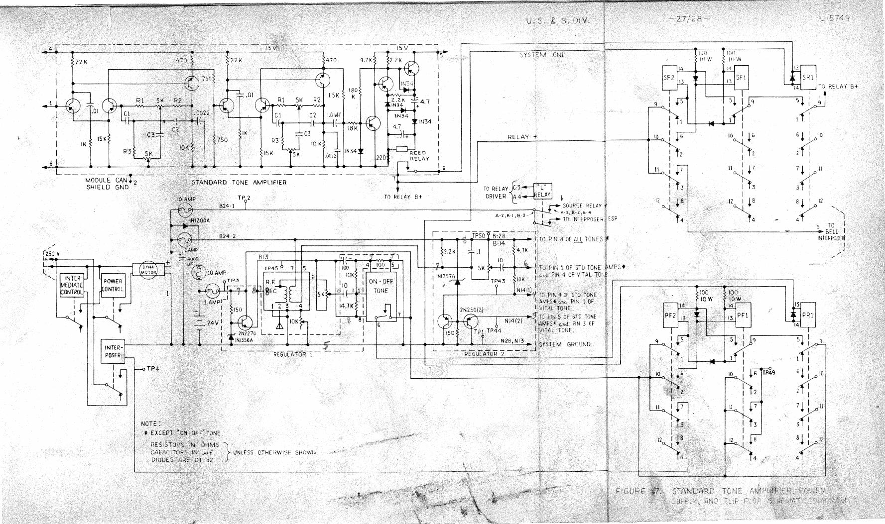
S.:~.;:idard Tone Amplifiel', Power Supply, and Flip-. 27 /28 Flop Schematic Diagram
LIST OF TABLES
Title Page
Power Supply Voltage Chart . <., . . .. . . . " .. " . • 12
Test Point Voltage Chart .. 13
Bridge and Trolley Courl'~ers Sequence Chart . 17
Hoist Counters Sequence Chart . . . . . . . . 18
U-5749
U. S. & S. Div. - 1 - U-5749
SECTION I
GENERAL INFORMATION AND OPERATING INSTRUCTIONS
1-1. PURPOSE Al'.J"'D DESCRIPTION.
The Crane Remote Control System provides a means of operating an overhead, unmanned, two hoist crane. All of the various crane funccions can be remotely controlled by an operator standing at or below ground level. The system is comprised of four units: a transmitter-controller, and a crane receiver and two interposer relay cabinets which are mounted in the crane.
a. . Transmitter-Controller. - The transmitter-controller is a battery operated unit, worn around the operator's waist, and by a heavy-duty leather belt. Modular con-struction and the use of solid state components provide for a small, compact, light-weight unit. Eleven tone oscillators, which are wired and bolted to a printed circuit board; a modu-
other , comprise the transmitter-con,.,. troller. The tone oscillator circuit board, and the modulator-transmitter are both attached to the transmitte~-controller frame.
Four ro.:.,,,;:ing switches, are located on the front panel of the unit, control the motions of the crane. Each rocking switch is comprised of two separate switches. The top half of the rocking switch operates one switch, and the bottom half operates the other switch. A stop switch is associated with each rocking switch and)s located below the respective rocking switch. There are two momentary switches located on the top of the unit; 1 one for operation of the crane bell and a bar operated dead.man switch power to the transmittercontroller. In addition, located on the front of the unit are a lockout toggle switch, and a crane power control switch. Control of power to crane is a special feature available, which en-ables the operator to turn crane power on off without having to climb up into the crane and eliminates the need for cumbersome cables.
~ocated '. ,3ide of the transmitter-controller are three mercury vertical interlocks, that will open if unit is held too far from upright position. This is a safety feature that removes ~)ower to the unit if the transmitter-controller is dropped, or if the operator falls. A diode, also located inside of the transmitter-controller, provides protection if a battery is inserted backwards into the unit.
b. Crane Receiver. - The crane receiver is a compact unit of modular construction consisting of a radio receiver, a vital tone amplifier, a relay driver, ten standard tone amplifiers, four counters, two flip-flop circuits, and various other electronic components.
A 24-volt storage battery is provided to voltage to the radio receiver, tone am-plifier ncn, and the associated relays. These components are used in the remote control of power to the crane, so they obviously require a continuous source of power. Vv'hen the crane

U. S. & S. Div. - 2 - U-5749
is operating, a dynamotor supplies voltage for these components, and also recharges the storage battery. The battery may require recharging by an external source if the crane has not been operated within a period of one month.
The modules of receiver box that is shock
crane receiver are all types, and are attached to a crane, a c:;,·~ne receiver case. The base of the receiver
case cov,2:r is bolted to the base. Electrical receptacles and terminals are located on relays, the storage ba:~·teI7, Lnc: the
1·ec0~ve:t case connections to the interposer
The cover of th-2 crane receiver box is ana relays of the flip-flop and .. counter circuits are mounted on top of this cover. Various electrical components are attached to the bottom of the receiver box cover. The remaining crane receiver modules are mounted inside of the receiver box.
c. Interoosa· Relavs. - The relays are contained iri two sheet-steel cabinets mounted on the crane. Refer to the addc:ndum on the interposer relays for a detailed description.
1-2. TECHNICAL
The following is a list of the technical specifications for the Crane Remote Control System.
TONE OSCILLATOR Fl'lEQUENCIES
Oscillator Frecruen~ias (cps)
c 184
D 213
E 248
F 288
G 334
H 387
J 450
K 534
L 607
M 705
0 950

U. S. & S. Div. - 3 - U-5749
TONE OSCILLATORS
Turn-on Time
Frequency Stability
Maximum Output Level to Resistive Mixer
Power Requirements
O. 1 second or less
f 0. 5%
1% or less
2 volts rms
12 to 15 volts at 2 ma. tone, 16 ma maximum
MODULATOR-TRANS1VII1'TER
Power Output
Frequency Stability
Modulation
Modulation Distortion
AM Output
FM Noise
Power Requirements
S$ 1 to final stage
± 0. 003%
:t 2. 5 kc total deviation
Less than 10% for any tone from 136 to 950 cps with deviation of 313 cps or 2500 cps
Less than 5%
30 below 313 cps deviation at 100 to 1000 cps
12 to 15 volts at O .2 ampere maximum
RADIO RECErvER
Sensitivity
Selectivity
12 db signal (plus noise; distortion to noise; plus distortion ratio) for input of 2 microvolts or less modulated with 1000 cps with a deviation of 313 cps
Greater than 12 kc at 6 db. Less than 32 kc at 60 db.
U. S. & S. Div. - 4 - U-5749
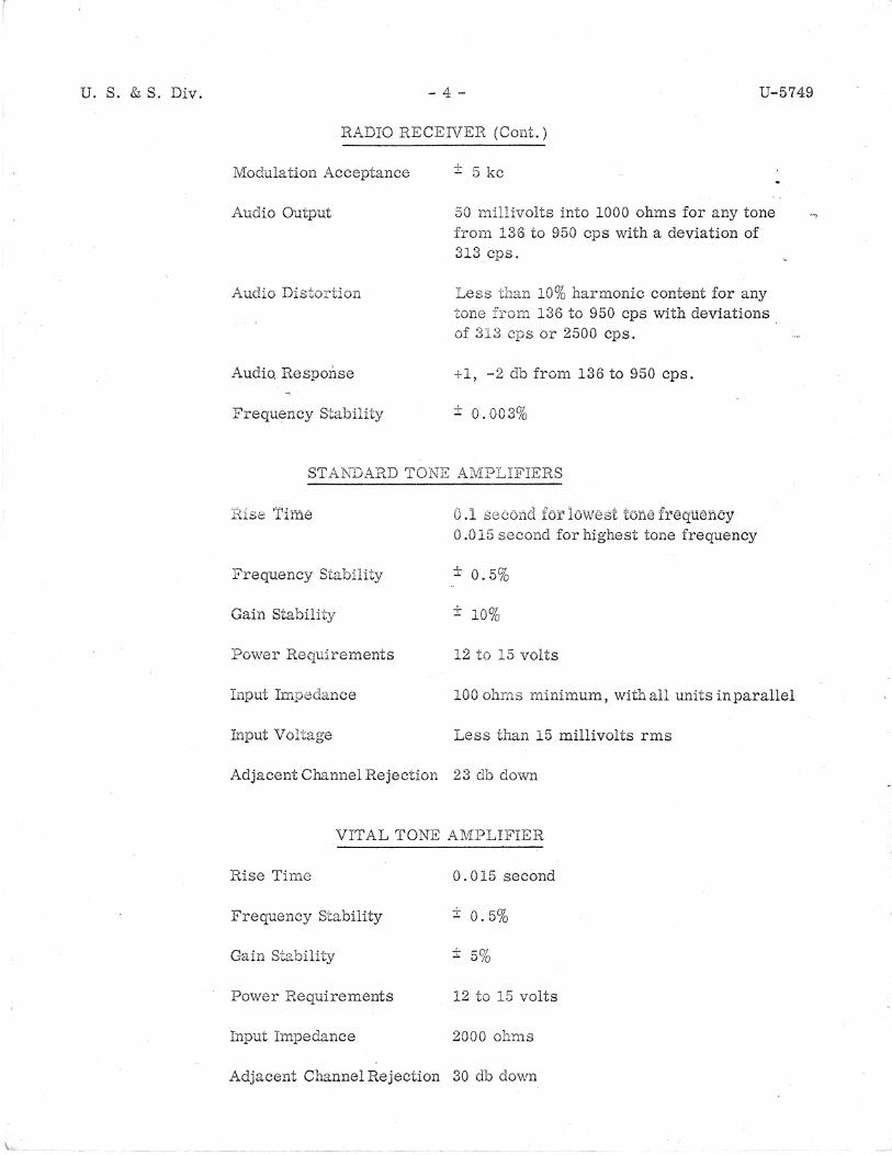
RADIO RECEIVER (Cont.)
Modulation Acceptance
Audio Output
Audio Distortion
Audio Response
Frequency Stability
± 5 kc
50 millivolts into 1000 ohms for any tone from 136 to 950 cps with a deviation of 313 cps.
Less 10% harmonic content for any tone from 136 to 950 cps with deviations . of 3l3 cps or 2500 cps.
+1, -2 db from 136 to 950 cps.
± 0. 003%
ST Ar,mARD TONE AMPLIFIERS
0.1 fat lowest frequency 0.015 second for highest tone frequency
Frequency Stability ± 0.5%
Gain Stability ± 10%
Power Requirements 12 to 15 volts
Input Impedance 100 minimum, with all units in parallel
Input Voltage Less 15 millivolts rms
Adjacent Channel Rejection 23 db down
VITAL TONE AMPLIFIER
Rise Time 0.015 second
Frequency Stability ± 0.5%
Gain Stability ± 5%
Power Requirements 12 to 15 volts
Input Impedance 2000 ohms
Adjacent Channel Rejection 30 db down
U. S. & S. Div. - 5 - U-5749
1-3. OPERA :NSTRUCTIONS.
The operating instructions consists of a list of operating controls and functions,: a brief description of use of the operating co:c,trols, and procedures for operating the crane.
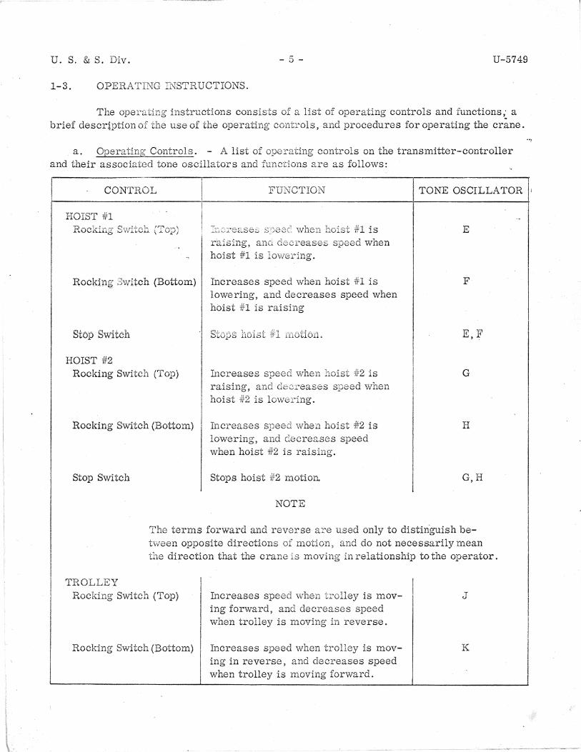
a. Operating Controls. - A list of controls on the transmitter-controller and their associated tone oscillators and functions are as follows:
CONTROL FUNCTION
HOIST iH
raising, when hoist #1 is lowering.
Rocki:ng· 3witch (Bottom) Increases speed when hoist #1 is lowering, and decreases speed when hoist #1 is raising
Stop Switch
HOIST #2 Rocking Switch (Top)
Rocking Switch (Bottom)
Stop Switch
fa creases when 4t2 is raising, and de:creases speed when hoist #2 is lowe1·ing.
focreases when hoist #2 is lowering, and decreases speed when hoist #2 is raising.
Stops hoist #2 motiort
NOTE
TONE OSCILLATOR ,
E
F
E,F
G
H
G,H
terms forward and reverse are only to distinguish be-tween opposite directions motion, and do not necessarily mean the direction that the crane is moving in relationship to the operator.
TROLLEY Rocking Switch (Top)
Rocking Switch (Bottom)
hlcreases speed trolley is mov-ing forward, and decreases speed when trolley is n1oving in reverse.
Increases speed when trolley is moving in reverse, and decreases speed when trolley is moving forward.
J
K

U. S. & S. Div.
CONTROL
TROLLEY (Cont.) Stop Switch
BRIDGE Rocking Switch (Top)
Rocking Switch (Bottom)
Stop Switch
BELL
CRANE
LOCKOUT SWirfCH
DEADMA .. N SWITCH
- 6 -
FUNCTION
Stops trolley motion
Increases speed when bridge is mov-
when bridge is moving in reverse.
Increases speed when bridge is moving in reverse, and decreases speed when bridge is moving forward.
bridge 1notion.
Controls the crane bell.
power to crane.
Mal{es ;;tvailable to the trans-mitter-controlle1~.
the to the
transmitter; makes voltage avail-able to the other tone oscillators.
U-5749
TONE OSCILLATOR
.J,K
L
M
L,M
D
c
0
b. Use of Controls. - The use of controls on transmitter-controller are as follows:
- Motion of Hoist #2 Hoist #1 or The operation is as follows:
or #2 is controlled by the Hoist #1 or are capable of operating at five different speeds.
When the switch (top) is depressed released for the time, the hoist 4Fl or #2 will raise in the first or lowest Each time rocking switch (top) is
and :.::1e speed will increase maximum is obtained. To slow down or move to a lov;o:c speed, the rocking switch (bottom) must be depressed and released. The tained.
switch will slow down the in reaching zero speed the hoist will stop, and when
until zero speed is obrocking switch (bottom) is
depressed and released again, the hoist will lower at its lowest speed. Each time the rocking switch (oottom) is depressed and released, the lowering speed will increase until maximum speed is obtained. To decrease the lowering speed, the rocking switch (top) must be depressed and released. rocking switch (top) will decrease the speed in step sequence until zero speed is again obtained.

U S. & S. Div. - 7 - U-5749
To immediately reset the f1oist or #2 from any step in either direction to zero speed, the stop switch must be
The terms forward and revctse are in the following between opposite directions
(2) Trolley or Bridge
the crane is
speeds. The operation rocking
to the operator.
or the bridge is controlled by the of operating at three
is basically the same as hoist speed in the forward direction, #1 or #2 described above. , The rocking switch
and decreases in reverse direction. the reverse direction, and decreases speed in ~he trolley or bridge to zero speed.
The switch (oottom) increases speed in
bell will ringing.
(4)
vdc power is
la tors pressed pc;-vv"Gr to crane
forward direction. The stop switch resets
released 1 crane and released, the bell wiil stop
switch is depressed and released, 250 The energized dynamotor converts the
is
battery. In addition, the 24 vdc two voltage regu
switch is again de-
(5) Lockout a:c1d Deadman Switches. - When the lockout switch is placed in the on position the bar operated deadman switch is held down, power will be applied to the trans-mitter-cor.troller.
c~ Gperatinrr Procedure. - To transn1it a
(l) carrier and
lockout switch, and hold down tone.
(2) Depress and release the crane on-off
(3) Depress and release the appropriate
NOTE
command proceed as follows:
deadman switch to t:cr,;Jsmit the r-f
to energize the crane.
to transmit a desired command.
The sequence of control will occur as described in para-6..raph 1-3, step b.
U.S. &S. Div. - 8 - U-5749
SECTION~ II
PRINCIPLES OF OPERATION
2-1. OVERALL FUNCTIONAL DESCRIPr.:.-'ION.
Crane co111n1ar:.ds :react . ..,l:e The command signals are added to
The tone rnod'cJated ;:;ar:rie1' is recc,i?ec. by fr,e c:::-ane receiver antenna. The radio receiver then recovers specially tuned tone . YVhen
c,n-r·ier, and directs them to by tr1eir correct tone, these amplifiers
control the operation of the crane. operate relays whic1.1 control voltages to
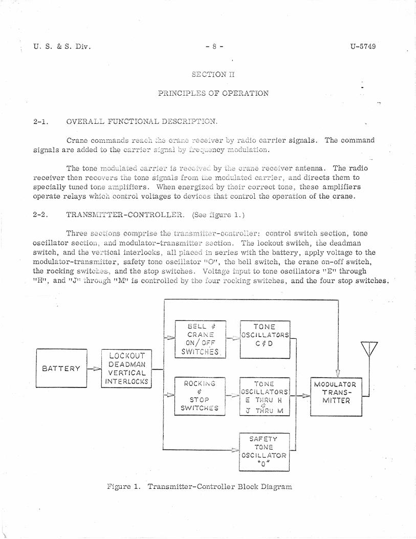
2-2. TRANSlViITTER-CONTROLLER. l.)
switch , tone oscillator section, lockout switch, deadman switch, and the interlocks, all JJ~·~~·~,., the battery, apply voltage to the
the bell switch, the crane on-off switch, modulator-transmitter, safety tone oscillator 11 011, the rocking switch2s., and the stop 11 H", and •1Jn
BATTERY
LOCKOUT DE ADMAN VERTICAL
INTERLOCKS
! I I I
~~ I
CRANE ON/ OFF
SWITC ES.
to tone oscillators "En through , and the four stop switches,
i I TONE ' I i , IOSC!LLATDRS ·1'---J ,.. .. D \., <;
I
Ii ·. I l I I ROCKli'<G j I TONE I MODULATOR
i-'>l ¢ L:.;;,)OSCll·l .... l\TORS Lr>-1.·. TRANS-,, II STOP I i E T::?U H I I · 1 MITTER ·. --s_w_i_T_c_i,.,_: _::::_s_· ... ' i .~r ·r ,Sr,' ! ' A J' I I ·---- \ v * i i ,-~ V r.ti _ I . I ......______. I i SAFETY ! l
---------i>I TONE u I OSCILLATOR 1-! "'o,, I
Figure 1. Transmitter-Controller Block Diagram
U. S. & S. Div. - 9 - U-5749
Each rocking switch tvvo asscci&.ted tone oscillators. rocking switch (top) energizes one tone swi~ch foottom) energizes other tone oscillator, and the stop switch tone oscillators simultaneously. The bell momentary switch energizes tone oscillator 11D11 , and tl:e crane on-off momentary switch~ en-ergizes tone oscillator 11 Cn. The output of tone oscillator section is coupled to the modu-.. , lator transmitter section, where an r-:f carrier of 72. 96 me is frequency modulated with the oscillator output, and transmitted to the crane :::-eceiver. Refer to paragraph 1-2 for the t?ne oscillator operating
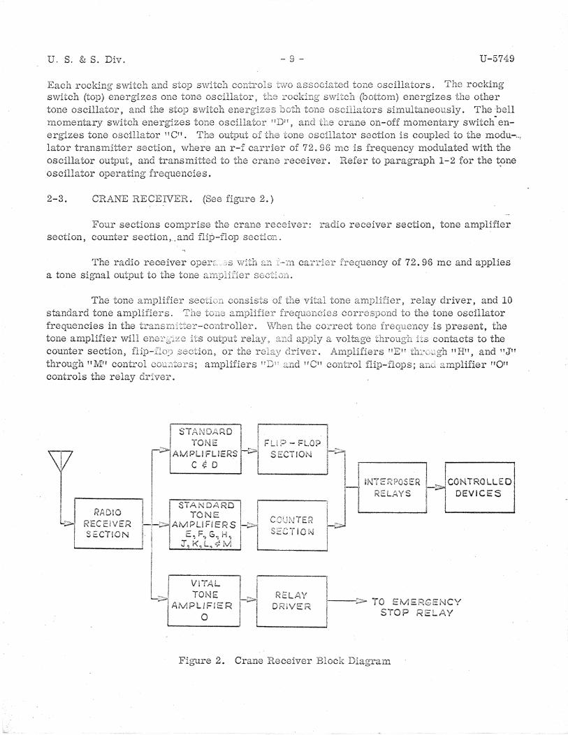
2-3. CRANE RECEIVER. (See figure 2.)
Four sections comprise section, counter section, .and
crane receiver: receiver section, tone amplifier sect:!.or.: ~
The radio receiver operr. a tone signal output to the tone
of 72. 96 me and applies
counter section,
, relay driver, and 10 tone oscillator
present, the
n Hn , and n J" through nMrr control cou.~r::ers; controls the relay
RECEIVER SECTiON
I STANDARD I ! ._ I •o I. .. ! . .• , _ FU;::> - FLOP , ...
r.,;.,"' AMPLI n SECTION r~ ...__c_$_o _ __,l .... ____ ___,! j ,....! ----.....
l I !NTER?OSER
I in . I RELAYS I I I STANDARD I I !I ...... , _____ __. I , TONE l "1
· ' I I I :\JTER i 1-\->iAMPUFIERS r>J :-;>.!
lcoNTROLLEO I DEVICES
! I E, F., G ,, H , I I SECT i O 1\1 I .._ _____ _.! ! , J, ~<~ L"i i.;; iV! ; .._ _____ ....,J
RELA't DRIVE i----:> TO EMERGE,~C'i
s·roP Ri=LAY
Figure 2. Crane Receiver Block Diagram

u. s. & s. - lO - U-5749
trolley com:ters: hoist #1 counter, hoist #2 counter,
C:;~Y .. mter is controlled by tone amplifiers 11 E11
fiers irJn and nKn control trolley counter, a::.1d bridge counter. The operation of each counter is energized by one tone amplifier for motion in one tion in the direction. The counters
speed
vqltage is applied to 001:.nter, direction of motion, and separate outputs for consist of a different combination for each
11 G11 and 11 Hn. Tone a:tnplinv1 and rt]Vpt control the
same. Each counter can be .. , and by one tone amplifier for moa sequence of steps that determine
the counter applies an output voltage for motion. The speed of motion outputs sequence. If both tone amplifiers simul-
taneously apply an input voltage to counter, the counter will supply no output voltage and reset to zero. outputs fror11 counter section control interposer relays. The interposer relays have low voltage coils and contacts that operate crane con-tactors.
The flip-flop section tone
outputs of these c::.:::·c-:,~.3
One is energized by ~ .... ,,~~ tone amplifier II C 11 • The
fo1" bell operation and the crane on-off interposer 1~0_s._y· ~·or operatio11 of t£.l.e c:::·ane power~
The output o:= -.::-... e driver ergizes the emergeEe:y stop relay.
2-4. COMMAl'-( ... ; SIGNAL FLOW.
The command. command uses a
tone oscillator oscillator 11 J 11 •
is by tf1e ... ::,~1e amplifier n Qn en-
7).
forward, first speed, trolley the same, except that the bell
and deadman on
are closed, voltage r-f carrier) and to the is also available to
, voltage is applied to voltage is applied to tone
from modulate
tone oscillator ~; ctio:~ 2.re to the modulator-transmitter sect:.i.or1, r-f carrie1~ ·._·~.d ar,~ ·~:·a11s111itted to the crane receiver ..
,,;\ft1e11 the frequency ca:rrie::::· is r·0.:;e:].·;;1ed at tl1e crane anten11a, the radio re-ceiver v1ill separate the tone them to the tone amplifiers. With the emergency stop relay energized power applied to the crane the on-off tone, tone amplifier nJn will accept to the trolley counter. The trolley counter will
trolley command, and relay voltage perform step one of its sequence.

U. S. & S. Div. - 11 -
output voltages will be interposer relays will the crane, and the crane will move at it 1s signal flow will be the same for subsequent speeds, will be applied to the required points.
SECTION HI
U-5749
output voltages will energize contactors will operate motors on
in a forward direction. The command except that the counter output voltages
MAINTENANCE
3-1. GENERAL.
The
and repair. Troubleshooting A Power Supply Voltage
the tcoubleshooting procedures. 7) which
of defec-tive modules, Instructions locating defective
relays, but do not cover the repair of these individual items.
3-2. TROUBLE
The instructions should be appropriate sche1T.1.atic diagran1s ~
To isolate ing instructio:ci.s.
a .. Power
following checks.
source of trouble to a
a power
Check both battery output voltages.
in
(3) Check items B and E as listed in T2~ble l.
counter sequence to assist in
Tables 1 and 2 and with
system function perform the follow-
or
lockout switch, and oscillator and tone am.,-
the
as necessary.
U.S. & S.
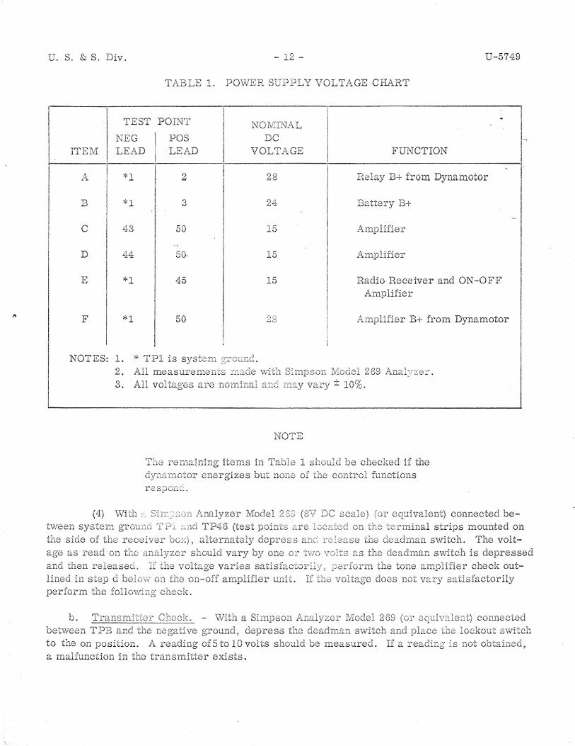
TABLE 1. POWER
TEST POINT
NEG POS ITEM LEAD LE.1.1.i..D
l>,. 2
B *l 3
c 43 50
D 44 50,
E *l 45
F *l 50
NOTES: 1. 2.
* TPl is
3.
tween
ag;e as read e,n and then released~ lined in
h '-'•
to the on position. a malfunction in transmitter exists.
NOIVHNAL
DC VOLTAGE
') ;.,!
24
15
15
15
.:;,,:-, -o
l\!OTE
U-5749
VOLTAGE CHART
FUNCTION L I
"0-1-.LJ ' I
I I
Battery B+
Radio Receiver and ON-OFF Amplifier
B+ from Dynamotor
connected be-
is depressed check out-
connected lockout switcl1
u. s. & s.
as 111rtde in ceiver
U-5749
, but a de variation is not obtained, :n:cdio receiver. Replace the radio re-
If a functio:;1 or n1otion ··'-·'-'-·'"u does ;.1ot res:pond (at any speed) and both·, the amplifier unit
c. output AC scale co:Tnected b;:;tween of 0. 25
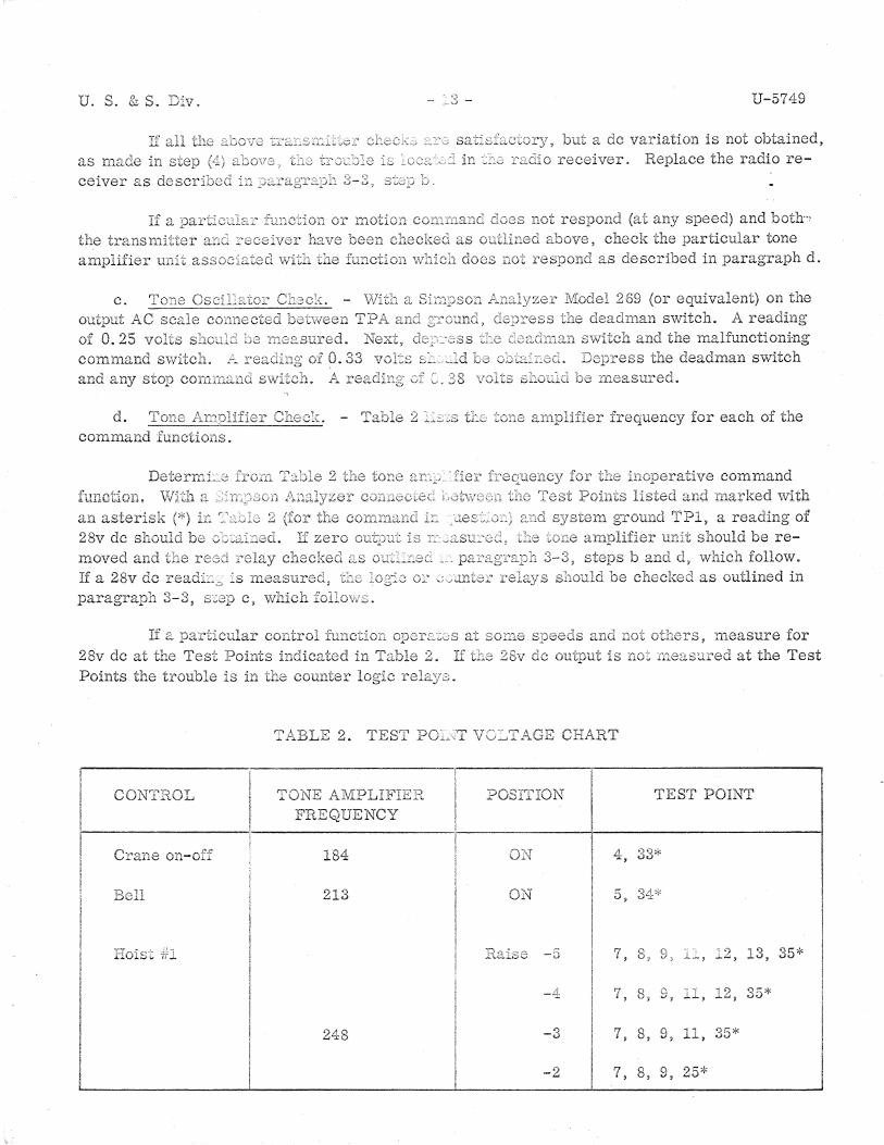
d. 2 - :s command functio:t,s.
If a 28v de paragraph 3-3,
28v de at the Test Points Points the trouble is in the counter
above, check the particular tone does 11.ot re
vclts s;:1otild
~.:011e
as de scribed in paragraph d.
(or equivalent) on the au.HJ.a..u switch. A reading
the malfunctioning deadman switch
frequency for each of the
d, which follow. checked as outlined in
:c:ot others, measure for at the Test
2. TEST po:;_,,;T VC'.;,_,T AGE CHART
CONTROL TOl~E AMPLIFIEl1 POS~trION TEST POINT FREQUENCY
184 ():\J 4, 33*
213 ON t:; v, 04·;<
liois-t Rc .. ise -0 7 8, ·; ') 13, 35* '
_:_,..;,..:, ~..;;..,
-4 7, 8, 'd -; ) ,') 35* .,, _ ...... , ~'-',
248 ..,
7, 8, 9, 4 ""\ 35* -0 .J.l.,
-2 7, 8, 9, 25*
U. S. & S. Div. _g_ U-5749
T AGE CHART (Cont.)
CONTROL POSITION TEST POINT
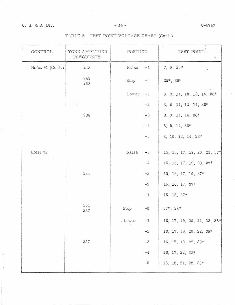
Hoist #1 (Cont.) 248 Raise 1 '7 8, 35* -.1. . '
-0 3i::* 36* .., ' 283
=--·OV/3"'!..~ 8, 9, 11, l? ..,, 13, 14, 36*
-2 9, 1 1 J.J..' 12, 14, 36*
288 -3 8, 9, 1 1 ........... , 14--, 36*
-4 8 , 9, 36*
-:) 8 , 10, , 14 -, 36*
Hoist Rs.ise -5 15, 16, 17, 19, 20, 21, 37*
-4 15, 16, 17, 19, 20, 37*
33!1 -3 1 r _o, 16, 17, 19, 37*
-2 15, 16, 17, 37*
-1 15, 16, 37*
334
I -0 37*, 38*
Lov10:/'< "'.i 16, 17, 19, 20, 21, 22, 38*1 -.i..
I
-2 16, 1 '7 ' " •)(\ 22, 38* I -·' ... ~ 01 ...,v,
387 -3 16, 17, 19, ')? -~, 38*
-4 16, 17, 22,
-5 16, 18, 21, 22, 33,:,
U. S. & 8. Div. - 15 - U-5749
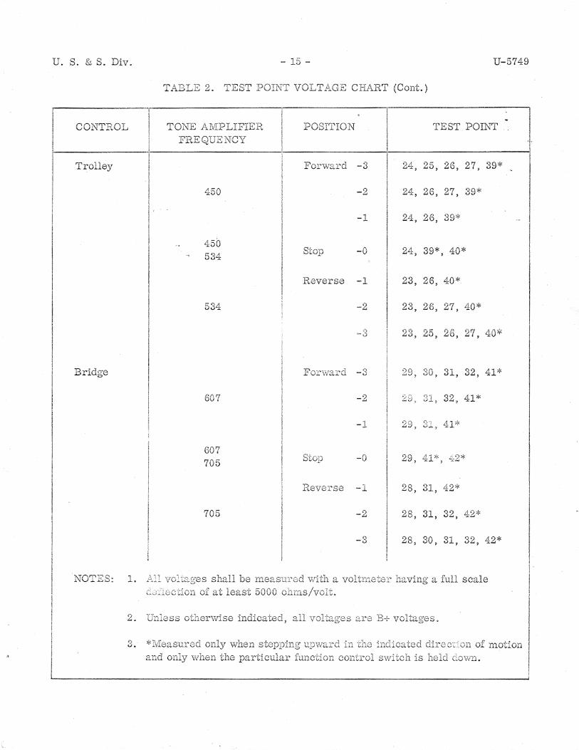
rfABLE 2. TES'T POIN':' VOL,-f P~GE CF.LA-RT (Cont .. )
I COl'TTROL TONE P:..IvIPLIFIER POSITION TEST POINT I
+ i
i Fli.EQUENCY :---------·-1-----------------------'--------------
i
Trolley
I
I
I i
Bridge
NOTES: 1 ..
2.. Unless
3. *I'vleas11r2d
450
450 534
-3
-2
-1
-0
Reverse -1
534 -2
607
607 705
705
shall be
indicated,
-3
-2
-l
-0
Re\rGrse 1 -.l.
-2
') -..,
a ·\roltrneter·
are B-r
24,
24,
24,
24,
23,
23,
29,
:20
90. ~..,,
29,
28,
28,
28,
25, 26, 27, 39*
26, 27, 39*
26, 39*
39*, 40*
26, 40*
26, 27, 40*
30, 31, 32, 41*
31, 32, 41*
') s 41* v,-,...'J
41*, L::2*
42*
31, 32, 42*
30, 31, 32, 42*
a full scale
of rnotion control svvitct1 is b.eld
I
I

Ul' S .. &S~ Div~
3-3. REPltlR~
of
c. individual
and
d. a tone
(1)
r11odules and
Tv -~l:ecl{ tl'1e
Rer.aove tone
·,-,,.,.., . ...,, ,.-~ IJV.U.V
the povver T:-le ofiYilr.r1eter Jnust
to
To a defective relay
(a) the circuit
U-5749
of removal and replaci.ement
To replace a defective module on all leads to the module, and re-
- 1-:,..1.1 of modules on crane receiver are crane receiver, remove case cover and remove
been isolated to a specific counter, the , one at a time, until the malfunction
as
manner, remove the 3 and 4. Tables 3
been isolated to defective, it
.f'ro1n tL.0 crane receiver, and remove the
to and connect an external circuit board.
across pins 6 and 7.
and ohmmeter
as
is n1ounted ..
circuit access to , and un-solder the relay
Remove and contact con.nections of the case.
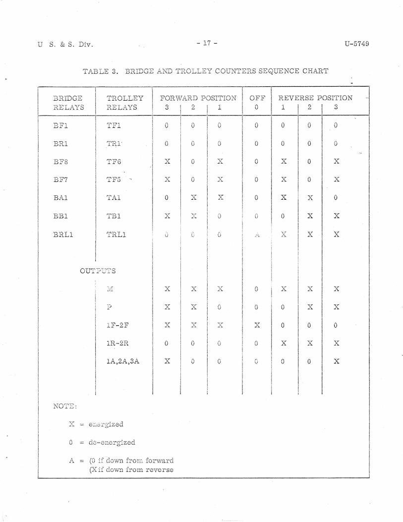
U S. & S. Div. - 17 - U-5749
T...AABLE 3~ BRIDGE P ... ND TROLLZY COUNTEli.S SEQUENCE CI-LP1.RT
BRIDGE TROLLEY FORWARD POSITION OFF REVERSE POSITION RELAYS RELAYS 3 2 1 0 1 2 3
0 0 0 0 0 0 0
BRl 0 {\ 0 0 0 0 0 v
BF8 'l"'F6 --ST 0 ,T 0 x 0 x .L;.. A
BF7 TF5 ,r 0 ,r 0 x 0 x ~";. _J's.
BAl TAl 0 ""C?"' A x 0 x x 0
BBl TBl ,,. "\_:r'
0 r- 0 x x .A .L>.. u
BRL1 ' u x x ,,.
OUT ~J -:_7;:: S
~vl x ,r )r 0 x ){ x A -"-
~J x "\.T L'- n
\I 0 0 x x
l1'""'-2F '<T x ·-;;r "'\)"" 0 0 0 A .L'::.. .L'>..
1R-2R 0 0 0 0 x x x
1A,2A,3A x 0 0 r 0 0 x v
NOT}~:
0
A = (0 if down fror.G down from reverse

. U. S. & S. Div. - 18 - U-5749
NCE CHART
HOIST 1-IOIST li.P.~ISE
11ELAYS R:S:.::.,AYS 5 L_!:
0
1qD1 A 0 0 0 0 0 0 \) v
I-IF2 r~J\Li '7 r, "'{T 0 ""'~r x 0 x 0 x .A. v -"- ..i'.::...
HFl ""'""--;"10 '<T 0 ,,;;r 0 ~T 0 x 0 ·v 0 x ..:-:.:..1.i 0 2'~ .!'.. ..L':.. A
HAl,2,3 I-:L .. J,~Lf , 5 'J 6 'V ·v 0 0 0 0 0 0 0 x x A ~"'-
HBl,2 FlB4,5,6 "\T 'i,'.r" ,r x 0 0 0 x x x x .1.\.. ..:·,._ ..i~
)( 0 0 0
HRl,2 •.:·,'.:? ·-:: 0 0 !"·1. 0 x x '<T x x ~ ............ fl..J v A
O f?I1 P-C"r:· S
p x -.;;r "-\T x 0 0 x ·v x x 0 ~"- ..!.--~ L'..
x x "ST v· "":T 0 0 0 0 0 0 Ji..&. 2\, L~ -"A
1\/'c-
lVi. x x "ST .L':c...
-er .b .. JC 0 x x x x x
lL-21..., 0 0 i\ 0 x x x x x v
lP}. x x 'CT 0 0 'CT x x 0 0 ..... ~ v -"-
2A x x 0 0 0 c x x 0 0 0
31~~ x 0 0 0 0 ('. x 0 0 0 x v
LP-1. 0 0 0 0 0 0 0 0 x
NOTE:
x ::;:

u.
HOIST • 1
HOIST •7.
BRID&E
R4 5K R3
101'< RB
CRM'1E
TONE OSC. ·r·
TONE OSC. . • G~
TO!-.IE OSC.. .H.
TONE OSC . • o·
OW-Off .___ ____ _,
s
u-
0$C CPS R1 R'Z. R3 C1 C1. C5 REMARKS
A - i
B -c 184 8.SK 1GOll 1.7K .O'SE -~ :a D 213 8.0K 1.7.S~ 1.K .OS~ .05b .1S
E 248 TOK 180k :3&l. .04\1 .047 .1.5 F 188 75K 1751< 1K .0?,9 .0!'>9 .1t
G 334 8.0K 11::iK iK .Ot:i3 .0'!:>3 .10
H ?fo7 10.0II 15.SII 1.81<. O'l.1 J:fl7 .082
j 450 8.0~ 170K tH .on 02.1 .Obs
K So4 7.01( ffl.OI! ~ .Q'l.2 .02.'Z. .068
l 607 80l< 1.1.Sk IW7sl .Q'l.8 .018 _osr;,
M 705 8.0k 180~ 1..5K .QiS 015 .041
N - " 0 950 1.om 1551< 11< .011. .012 0~3 SAFETY
NOTE: C1,C2.,C3, 51-lOWN IN µf~.
TPA
MOD;.JLAT~ -----TRAN~M\HER ..__ ____ ___.
\~T$-I
1PB

u. s. & s. u-
RELAY B+ 184 "' iP33 ON-OFF
8 TO ON-OFF FLIP-FLOP 7 PIN •13 OF PR 1
21:!f N TO PIN 7 OF BELL REG•1 TP34
8 TO BELL FLIP-FLOP STD TONE AMP"E s PIN •13 OF 9R 1 248N NOi.ST • I
6 TP35 UP} 8 UP PIN •13 OF HU1
STD TOME ANIP ·r 5 7 288N 1 TO HOIST •1 COUNTER HOIST• 1
6 TP3~ DOWN a DOWN PIN •13 OF H01
4 5 1 334 N
WOIST •2 TP37 u] 8 UP PIN •13 OF HU2 STO TONE AMP ·11 5 387 N 1 TO HOIST •2 COUNTER HOIST •2 TP38t DOWN
8 OOWN G • PIN •13 OF H02 AMJIO 4 STO TON£ AMP 'J 5 RECEIVER
1 •SON
- TROLLEY TP39 FWD 6 POWER 8 l"ORWARO } PIN•t4 OF TF!
SllflPI.Y 4 STD TONE AMP•K 5 7 i 5'!14 N 7 TO TROLLEY COUNTER
TROI...LEY 6
TP40 REV TP4G 8 REVUtSE PIN• 14 OF TR1
4 STD 'n>Wli'. ~·1.: 5 1 607N
TP41 8RrDliE 6 FWD} PIN• 14 OF BF 1 8 FORWARD
4 STD TONE AMP' 5 7 1 705 tv 7 TO BRtOGE COUNTER
BRtOGli 6
TP42 REV 8 REVERSE PIN•14 OF BR1
VITAL TONE AMP •o' MODULE: CAN
~0~ - - - - j ~IE...!:;0!!80.;_ - - - - ---- -
100 470
I I I
D1-s216
----------- - - - - - - -- ____ ....., -"~-----• '
I LT NE
RELAY ORIVER
4
~ TO
EMERGENCY STOP REL.~Y { DE~OMAM)

RELAY B+--~~-+-~~~~~-t-~~~~~~-4~_...,....:.;...,....:.;........;.~~~~~~~~-+~~~-+-~~~~~~~~~~--l-~~~--~~~~~-1-~~~~~~~~~~~~~~-t-~~~~~~~+-~~~~+-~~-t-~~~~
SYSTEM GROVNO ....... ~~-t-~~.....-~~t-~~~--.,-.~-t--..-:--~~--~~~...-~~~-t-~~~t-~~~~~~+-~~-+~-+--~---.-~~~~-+-~~~~~~---,1--~~-~~--.--t--..-~~-1r-~~-,-~~~~i---,.---,--.~~~i--~~~~~~·~;--,.--,
HOIST REVERSE
HOIST FORWARD 13
HU1 14 HD1
HU2)
10
2
II 11
12
4
NOTES: l. OESIGNATlONS ENCLOSED IN PARENTHESIS ( )
INDICATE HOIST '* 2. 2. All DIODES, ARE TYPE OI-52.
13
14
9
6 10
12
13 13 HA3 14 14 HA2 HAl 14
HAG) (HAS) {HA4)
I I is l 9 q I
ii
I I
12 12 I
4 4
13 13 13
14133 14 HB2 14 14 H81 HC2 14 14 HC1 HR1 14 14 HR2
HBG) HB5) • H84) HC4) IIC3) (HR4)
I : +s I 5 5 5 q 9 9 <t I I
1 1
10 10 10 G
1 II
12
4
TP{22~ TPl4
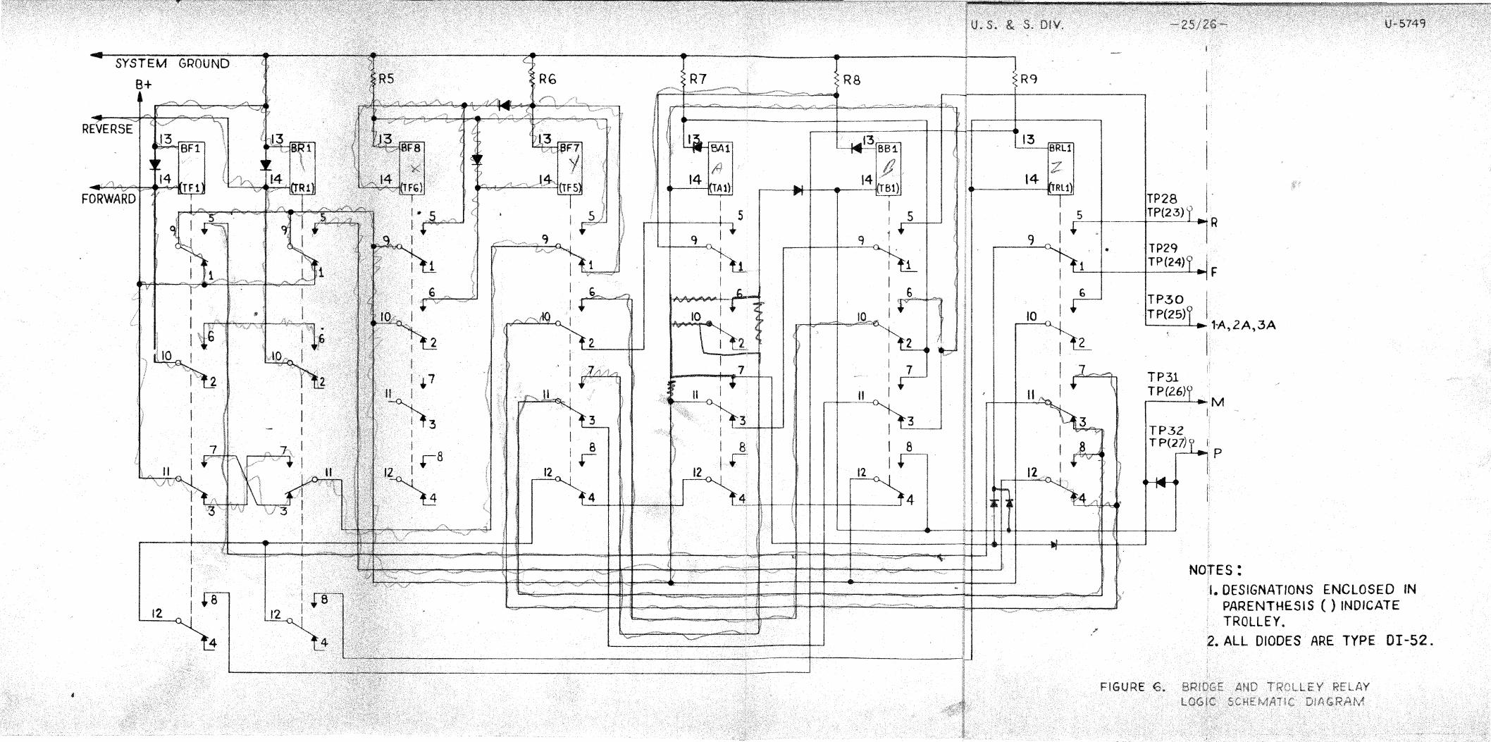
SYSTEM
B+ R7 RS
~,-,,,~
BF1
14 FORWARD
5
q
I I 10
-;;,}'
l 6 " 2 j 10 I ,,,tOr
~ 1 7
I " I h3 3 I I
I 7 8 I 8 8 l r 1r·
12 12
4 4
12
R9
13
14
I 5 .--9 I ..
1
6
10
]
ll
3
12
TP28 j. TP(23)t.; R
rp2q TP(24)
TP30 TP(25)
TP31 TP(2.6)
TP32 TP{27)
I
F
1-A,2A,3A I
I I
.M I
I p
r
NO\TES: I. DESIGNATIONS ENCLOSED IN
PARENTHESIS ( ) INDICATE TROLLEY.
2. ALL DIODES ARE TYPE OI-52.
8
.I I I I I
22 K
L __ MOOULE CANT2- -· .._.... SHIELD GND
/ /
~so v L-.i-----------~
"' ..... INTERMEDIATE
ONTROL
INTERPOSER"
ISK
---------- - -- -- ------- -7
I
I I 6
RELAY +
TONE AMPLIFIEA ----------+-' TO RELAY f 3--f~
TP 2 TO RELAY 8+ DRIVER ~4..,._f~ t
.~-.......,...-·.;.;..82_4_·_1 --''---------------------------+---,...------o-J! ~ SOVRCE RELAY A-2 Bl !3<3·/ I "--A-1,8.·2,tl-4
824-2
Bl.3
TP45 7 5
SK
3 4
IOK I I _______ .J
OTHE~W15c SHOWti
ON-OFF
TONE
7
2.2K
I l INl357A
I I I I I I
SK
' ' .-~ TO INH-PPOSE
TP43
Nl4(2)
N28 N13 GROUND L----·· ...... -----REGULA!OR 2
10
SF2
I I
14
13
z
11~~
IJO \()0 \() w
14
13 SF!
5
I I
10 I i G
!'tz l
II I i 7
!)3 I
12 I i 8
)4
9
6
2
13
..... '
13
PRl
14
I I
fi i I TP49 ~10
2 I .
7 i I u
3fi I
:f''