ua tech park development guidelines - tech parks … ua tech park...the ua tech park development...
TRANSCRIPT

UA Tech Park Development Guidelines
Sustainable Technologies Best Address
October 3, 2012

UA Tech Park Development Guidelines
The Solar Zone @ The UA Tech Park
AMONIX Solar Field
UA Tech Park Development Guidelines
Rev: 10-03-2012 Table of Contents: Page 1
Tab le of Contents Section I: Instructions to Users ............................................................................................................ 5
The University of Arizona Tech Park Guide............................................................................................................ 5 The UA Tech Park Development Guidelines .......................................................................................................... 5 Development at the UA Tech Park ......................................................................................................................... 7 How to Use this Document ..................................................................................................................................... 8
Section II: Introduction and Overview ................................................................................................ 11
Overview of the UA Tech Park ............................................................................................................................. 11 Physical Description .............................................................................................................................................. 11 The Development Guidelines ............................................................................................................................... 12 The UA Tech Park Master Plan ............................................................................................................................ 13 The UA Tech Park Land Use Plan ........................................................................................................................ 13 Guiding Principles ................................................................................................................................................. 13 Development Framework ...................................................................................................................................... 13 Initial and Short-Term Development Focus .......................................................................................................... 14 Development of New Facilities ............................................................................................................................. 14 Objective of the Development Guidelines............................................................................................................. 14
Section III: Development Plan ............................................................................................................. 17
UA Tech Park Land Use Plan ............................................................................................................................... 17 Developed and Undeveloped Acreage ................................................................................................................. 18 Land Use Designations ......................................................................................................................................... 18 Assembly/Manufacturing ...................................................................................................................................... 18 Regional Commercial............................................................................................................................................ 18 Commercial ........................................................................................................................................................... 19 Business Development ......................................................................................................................................... 19 Hospitality ............................................................................................................................................................. 19 Research Park ...................................................................................................................................................... 19 Public Use ............................................................................................................................................................. 20 Residential ............................................................................................................................................................ 20 Education .............................................................................................................................................................. 20 Open Space/Golf Course ...................................................................................................................................... 20 Davis-Monthan AFB Dedicated Open Space Corridor ......................................................................................... 20 UA Tech Park Gateways and Signature Entry Boulevards .................................................................................. 21 UA Tech Park Overlay Zones ............................................................................................................................... 21 UA Solar Zone Overlay Zone ................................................................................................................................ 21 Low Intensity Office Overlay Zone ........................................................................................................................ 21 UA Tech Park Center Overlay Zone ..................................................................................................................... 21 The UA Tech Park Plaza ...................................................................................................................................... 22 UA Tech Park Activity Nodes ................................................................................................................................ 22 Kolb Road Activity Node ....................................................................................................................................... 22 Pantano Road Alignment Activity Node ................................................................................................................ 22 Rita Road Alignment Activity Node ....................................................................................................................... 22

UA Tech Park Development Guidelines
Rev: 10-03-2012 Table of Contents: Page 2
Section IV: General Guidelines (Non-Residential Development) ....................................................... 25 A. Site Planning ................................................................................................................................................... 25 B. Stormwater Management/Drainage ................................................................................................................ 40 C. Circulation and Access .................................................................................................................................... 43 D. Pedestrian and Bicycle Circulation.................................................................................................................. 58 E. Parking Lots and Parking Structures ............................................................................................................... 70 F. Architectural Design......................................................................................................................................... 79 G. Landscape ....................................................................................................................................................... 88 H. Signage ........................................................................................................................................................... 96 I. Site Furnishings ............................................................................................................................................ 111 J. Lighting .......................................................................................................................................................... 112 K. Open Space ................................................................................................................................................... 120 L. Information Kiosks ........................................................................................................................................ 126 M. Wireless Communication Facilities ............................................................................................................... 127 N. Development of Solar Generation Facilities within the Solar Zone ............................................................... 131
Section V: Residential Development Guidelines ............................................................................. 137
A. Land Use and Site Design ............................................................................................................................. 137 B. Community Character and Design ................................................................................................................ 141 C. Minimum Standards for Single-Family Residential Development ................................................................. 144 D. Zero-lot-line Residential Development .......................................................................................................... 147
Section VI: Specific Development Guidelines ................................................................................. 158
Introduction ......................................................................................................................................................... 158 A. Development Intent ....................................................................................................................................... 159 B. Development Standards for Non-Residential Development ......................................................................... 162 C. Specific Development Guidelines ................................................................................................................. 167
Research Park - Laboratory ......................................................................................................................... 168 Research Park – Office ................................................................................................................................ 172 Assembly/Manufacturing .............................................................................................................................. 173 Business Development ................................................................................................................................. 176 Surface Parking and/or Parking Structures .................................................................................................. 179 Hospitality ..................................................................................................................................................... 182 Regional Commercial ................................................................................................................................... 185 UA Tech Park Plaza Overlay Zone .............................................................................................................. 188 Tech Park Center Overlay ............................................................................................................................ 191 Low-Intensity Office Overlay Zone ............................................................................................................... 194 Davis-Monthan Air Force Base Dedicated Open Space Corridor ................................................................ 197 Davis-Monthan AFB Approach/Departure Corridor: Standards for Development ....................................... 198
Appendix A: Plant List and Plant Catalogue ..................................................................................... 199 Appendix B: Cross-Reference Matrix ................................................................................................ 248
Appendix C: Definitions ..................................................................................................................... 249 Appendix D: Bibliography and References ....................................................................................... 257
List of Figures
Figure 1: Project Area ............................................................................................................................................ 9 Figure 2: UA Tech Park Land Use Plan............................................................................................................... 15 Figure 3: UA Tech Park Activity Nodes and Overlay Zones ................................................................................ 23 Figure 4: Davis-Monthan Air Force Base Approach/Departure Corridor ............................................................. 39 Figure 5: UA Tech Park Conceptual Trail Park System .................................................................................... 123

UA Tech Park Development Guidelines
Rev: 10-03-2012 Table of Contents: Page 3
List of Tables
Table 1: UA Tech Park Development Guidelines ................................................................................................... 6 Table 2: UA Tech Park Land Use Plan: Land Use Designations and Corresponding Acreages ....................... 107 Table 3: Minimum Bicycle Parking Requirements ................................................................................................ 68 Table 4: Handicapped or “Barrier Free” Parking Standards ................................................................................. 72 Table 5: Minimum Standards for Surface Parking Lots ...................................................................................... 107 Table 6: Signage Guidelines Summary .............................................................................................................. 107 Table 7: Levels of Illumination ............................................................................................................................ 118 Table 8: Minimum Parking Rates for Residential Development ......................................................................... 140 Table 9: Minimum Buffer Yards Requirements ................................................................................................... 142 Table 10: Minimum Standards for Single-Family Residential Development ...................................................... 146 Table 11: Minimum Standards for Multi-Family Residential Development ......................................................... 156 Table 12: Supplemental Standards for Multi-Family Residential Development ................................................. 157 Table 13: Acreage Inside and Outside of the Project ......................................................................................... 158 Table 14: Development Intent ............................................................................................................................. 164 Table 15: Development Standards for Non-Residential Uses ............................................................................ 164

UA Tech Park Development Guidelines
Rev: 10-03-2012 Table of Contents: Page 4
The University of Arizona Office of University Research Parks

UA Tech Park Development Guidelines
Rev: 10-03-2012 Instructions to Users: Page 5
Section I: Instructions to Users
The University of Arizona Tech Park Guide The University of Arizona Tech Park Guide (UA Tech Park Guide) comprises three major volumes: The University of Arizona Tech Park Master Plan (UA Tech Park Master Plan), The University of Arizona Tech Park Development Guidelines (UA Tech Park Development Guidelines) and the University of Arizona Tech Park Project Operation Agreement (Project Operation Agreement). These documents are further defined in the UA Tech Park Master Plan. Illustration 1 depicts the UA Tech Park Guide organizational structure.
Illustration I: UA Tech Park Guide Organizational Structure.
The UA Tech Park Development Guidelines This UA Tech Park Development Guidelines volume sets development standards and design guidelines for the development of the University of Arizona Science and Technology Park (UA Tech Park). This planning document mirrors its companion volume, the UA Tech Park Master Plan. The master plan includes development precepts, the land use plan, and broad policy for the development of the UA Tech Park. These development guidelines contain expansion precepts, development plans for future expansion, and specific standards for the development of land use parcels within the UA Tech Park. The UA Tech Park Master Plan and the UA Tech Park Development Guidelines should be consulted when planning development at the UA Tech Park. Major sections of this volume are described in Table 1.
UA Tech Park Guide
The Project Operation Agreement
UA Tech Park Development Guidelines
UA Tech Park Master Plan

UA Tech Park Development Guidelines
Rev: 10-03-2012 Instructions to Users: Page 6
Table 1: UA Tech Park Development Guidelines
Section Name:
Section Intent:
Section I: Instructions to Users
Provides instructions on how to use the different sections included in the Development Guidelines volumes
Section II: Introduction Provides an overview of the UA Tech Park.
Section III: Development Plan Lays out the key components of the development plan.
Section IV: General Guidelines (Non-residential Development)
Includes guidelines and development standards for the development of non-residential development.
Section V: General Guidelines (Residential Development)
Provides guidelines and development standards for the development of residential development.
Section VI: Specific Development Guidelines
Provides specific guidelines and development standards for non-residential land use parcels located outside of the Project Area.
Section VII: Development Review Process
Includes the UA Office of University Research Parks Development Review Process
Appendix Section Includes: Plant palettes and Plant Catalogue. Compliance Cross-Reference Matrix Definitions Bibliography
Section I of this document includes instructions to users. Section II of this volume includes the introduction and overview. Section III lays out the components of the development plan. Section IV includes general development standards and design guidelines for non-residential development located outside of the Project Area and for new development in the Project Area. These general guidelines also apply to future equivalent uses identified in the UA Tech Park Master Plan. Development standards and/or development guidelines provided within this section meet and/or exceed adopted local development standards and guidelines. In addition, the Development Guidelines meet and/or exceed the sustainable sites and water efficiency standards recommended by Leadership in Energy and Environmental Design (LEEDTM) Green Building Rating System, the national standards for environmental performance summarized in LEED 3 Green Building Rating Systems prepared by the U.S. Green Building Council. This section of the Development Guidelines is grouped into the following chapters:
Site Planning
Stormwater Management/Drainage
Circulation and Access
Pedestrian and Bicycle Circulation
Parking Lots and Parking Structures
Architectural Design
Landscape
Signage

UA Tech Park Development Guidelines
Rev: 10-03-2012 Instructions to Users: Page 7
Site Furnishings
Lighting
Open Space
Information Kiosks
Wireless Communication Facilities and Cell Towers
Development of Solar Generation Facilities within the Solar Zone
Section V of this document includes development standards and design guidelines for single-family attached and detached, zero-lot-line, and multi-family residential uses located outside of the Davis-Monthan AFB Approach/Departure Corridor. Section VI of this document provides development intent and specific development standards for non-residential land uses identified in the UA Tech Park Land Use Plan provided in Figure 2. In addition, Section VI includes specific development standards for development within the Davis-Monthan AFB Approach/Departure Corridor. Non-residential development must comply with all applicable development standards and design guidelines provided in Section IV and Section VI of these Development Guidelines.
Development at the UA Tech Park
This document must be used in conjunction with the UA Tech Park Master Plan. All development within the UA Tech Park must:
Follow the Development Review Process included in Section VI of the UA Tech Park Master Plan;
Further the development precepts and the policy direction provided in the UA Tech Park Master Plan;
Comply with the development standards and design guidelines included in these Development Guidelines; and
Be approved by the UA Office of University Research Parks Design Review Committee.

UA Tech Park Development Guidelines
Rev: 10-03-2012 Instructions to Users: Page 8
How to Use this Document There are two ways to use this document. If you have a topic in mind (landscape, circulation and access, architectural style, signage, etc.) and are looking for more information, you can go directly to the specific chapter using the Table of Contents. Chapters in Sections IV and V include general development standards and design guidelines arranged by topic.
A second method is to identify a land use within the UA Tech Park Land Use Plan and find such land use in the Compliance Cross-Reference Matrix located in Appendix B of this document. This matrix provides compliance cross-reference for each land use designation and overlay zone identified in the UA Tech Park Land Use Plan. Figure 1 shows the Project Area. Figure 2 shows the UA Tech Park Land Use Plan.

UA Tech Park Development Guidelines Section I: Instructions to Users
Rev: 10-03-2012 Figure 1: Project Area: Page 9
Figure 1: Project Area

UA Tech Park Development Guidelines Section I: Instructions to Users
Rev: 10-03-2012 How to Use this Document: Page 10
This page corresponds to back of the 11x17 graphic to keep correct pagination.
Do not include this page in the original document.

UA Tech Park Development Guidelines Section II: Introduction
Rev: 10-03-2012 Introduction and Overview: Page 11 Overview of the UA Tech Park: Page 11
Section II: Introduction and Overview
Overview of the UA Tech Park The UA Tech Park is one of the nation’s premier research parks, where higher education and industry come together to develop and apply new technologies. The purpose of the UA Tech Park is to provide a world-class environment that supports the transfer of scientific knowledge from the research laboratory to emerging rapid-growth companies as well as to mature technology-based industries.
The UA Tech Park is an integral component of Southern Arizona’s economic development strategy. The UA Tech Park houses high technology companies such as NP Photonics and multinational corporations such as the Raytheon Company and IBM. Also, it is the home to the Arizona Center for Innovation, educational facilities serving high school through graduate-level students, and University of Arizona laboratory facilities. Physical Description The UA Tech Park is located in Pima County, Arizona, in the southeast quadrant of the Tucson metropolitan area. Its physical address is 9000 S. Rita Road, Tucson.
Adjacent to Interstate 10, between Kolb Road and Rita Road exits, the UA Tech Park is approximately 25 minutes from the University of Arizona’s main campus and approximately 15 minutes from the Tucson International Airport. The neighboring community encompasses Davis-Monthan Air Force Base, the Target Fulfillment Center, Global Solar, Arizona Canning Company, Rita Commerce Park, the Southpoint Industrial Park and several residential developments, including Rita Ranch, Rocking K, Civano, La Estancia, Rancho del Lago and Academy Village. The UA Tech Park occupies a 1,345 acres site. Of this total acreage, approximately 323 acres are currently designated the Project Area. An additional 23 acres have been developed for the Vail Academy and High School. The Solar Zone at the UA Tech Park (UA Solar Zone) is the largest multi-technology solar generating facility in the world, encompasses 200 and is currently approaching buildout. The remaining 799 acres are undeveloped at this time. There are some parcels available for infill development and tenant expansion within the Project Area. The Project Area is adjacent to and west of Rita Road, lying between the Union Pacific Railroad and Interstate 10. All of the existing buildings and infrastructure within the UA Tech Park are located in this area. The Project Area is governed by the Project Operation Agreement. The UA Tech Park consists of 13 primary buildings and several smaller support buildings and facilities. These structures total 2 million square feet of developed space and 1.9 million square feet of leasable space. Primary buildings are set on two major grids, which lie at 45-degree angles to each other. A covered spine, aligned north/south through the center of the facility, interconnects all primary buildings. The spine serves a dual purpose. It is a pedestrian linkage between the buildings as well as a mechanism for distributing electrical power, communications cable, and plumbing for heating and cooling, and domestic and deionized water to all buildings.

UA Tech Park Development Guidelines Section II: Introduction
Rev: 10-03-2012 Introduction and Overview: Page 12 The UA Tech Park Development Guidelines: Page 12
The UA Tech Park has a separate industrial wastewater collection and treatment system. The industrial wastewater collection system collects waste from five separate waste streams and conveys them in separate pump stations and pipes through a monitored trench system through the site. Not all buildings within the UA Tech Park are served by this system. They are only allowed to discharge certain industrial wastes to the system. All services are currently provided for on-site. Although electrical power and natural gas are also provided, these services are generated off-site. On-site wells provide water for UA Tech Park tenants, and a central plant meets the UA Tech Park’s heating and cooling needs. Support service facilities include a sanitary sewer treatment plant and an industrial wastewater treatment plant. Recycled water is produced by the UA Tech Park’s treatment plants, which provide water for cooling towers in the central plant, fire protection in storage tanks, and landscape irrigation.
UA Tech Park Utilities Spine, Industrial Waste Water Treatment Facility and Rail Road Spur An on-site cafeteria provides food services and indoor and outdoor seating for 1,200 individuals. The UA Tech Park’s outdoor recreation facilities include basketball and tennis courts, softball fields, jogging and bike paths, and an exercise course. The Julian Wash Regional Trail was recently completed along the north boundary of the UA Tech Park with a Trail Head along Kolb Road. This regional trail system provides connectivity to adjacent development and provides a window into the UA Solar Zone. The 799-acre undeveloped area extends from the west end of the Project Area to Kolb Road. The majority of this land is relatively flat and sparsely vegetated with native species. The Julian Wash, a naturally occurring watershed and riparian zone, bisects the area from east to west. The undeveloped area includes environmentally sensitive lands. These lands include 10 archaeological sites and 163 acres of floodplain and riparian zones.
The UA Tech Park Development Guidelines Ancillary to the UA Tech Park Master Plan are these development guidelines. They serve as the primary implementing mechanism for the UA Tech Park Master Plan. These guidelines provide appropriate flexibility to anticipate future needs, to achieve compatibility between land uses and to ensure sustainable development. The purpose of these guidelines is to establish criteria that communicate the standard of development and level of quality expected throughout the UA Tech Park. They are a means of monitoring and directing development in the UA Tech Park. They assure the high quality construction that will enhance the community, advance the University’s goals for research and development and provide a stable and attractive climate for investment.

UA Tech Park Development Guidelines Section II: Introduction
Rev: 10-03-2012 Introduction and Overview: Page 13 The UA Tech Park Master Plan: Page 13
The UA Tech Park Master Plan The UA Tech Park Master Plan functions as the long-term development plan or the comprehensive plan for the UA Tech Park. Basic development parameters, including land use, are defined in the UA Tech Park Master Plan. The UA Tech Park Master Plan includes the overall physical plan for the UA Tech Park and provides development precepts and supporting policies that serve as the tools for plan implementation. The overall physical plan for the UA Tech Park is defined in the Development Plan section of the UA Tech Park Master Plan. The Development Plan establishes the overall character of development, location and character of vehicular roadways and bicycle/pedestrian routes, and the location and definition of development zones. Environmental constraints, including those for the Julian Wash area and regulatory constraints within the Davis-Monthan Air Force Base Approach/Departure Corridor are addressed in the UA Tech Park Master Plan. The Implementation section of the UA Tech Park Master Plan provides mechanisms for implementing it.
The UA Tech Park Land Use Plan The UA Tech Park Land Use Plan identifies 12 land uses, shown in Figure 2: UA Tech Park Land Use Plan. Of these 12 land uses, a total of 3 land use designations correspond to different forms of open space: Open Space/Golf Course; Davis-Monthan AFB Dedicated Open Space; and Signature Entry Boulevard. These 12 land uses occupy a total of 1,345 acres and are defined in the UA Tech Park Land Use Plan chapter included in Section III: Development Plan.
Guiding Principles These development guidelines implement the principles established in the UA Tech Park Master Plan. These principles are listed in the UA Tech Park Master Plan and provide a framework for decision making related to the development and operation of the UA Tech Park.
Development Framework A comprehensive framework of planning documents guides future development of the UA Tech Park. The UA Tech Park Development Guidelines provide development standards and guidelines necessary to implement the long-range vision, development precepts, goals, and policy direction established in the UA Tech Park Master Plan.
All planning documents are available upon request from the University of Arizona Office of University Research Parks, 9070 South Rita Road, Suite1750, Tucson, Arizona, 85747 or by calling (520) 382-2480.
Initial and Short-Term Development Focus Because IBM originally designed the Project Area as a single-user facility, the UA Tech Park’s initial development focus has been to turn the site into a facility that can be effectively occupied by multiple tenants. A progressive transition towards multi-tenancy has characterized the initial focus of development at the UA Tech Park and will continue to characterize near-term development. Initial efforts to achieve multi-tenancy are described in the UA Tech Park Master Plan.

UA Tech Park Development Guidelines Section II: Introduction
Rev: 10-03-2012 Introduction and Overview: Page 14 Development of New Facilities: Page 14
Development of New Facilities The UA Tech Park is divided into 12 land use areas, which define the nature and location of UA Tech Park facilities. All future development of the UA Tech Park shall be consistent with the land uses defined in the UA Tech Park Master Plan. The University will consider the construction of single tenant, multiple-tenant, or built-to suit properties. New facilities must meet all specifications outlined in these development guidelines. A variety of options may be used for the development of new facilities. These options are listed in the UA Tech Park Master Plan.
Objective of the UA Tech Park Development Guidelines
The purpose of these development guidelines is to establish criteria that communicate the standard of development and level of quality expected throughout the UA Tech Park. These development guidelines are intended to:
Create a modern, progressive, high tech business environment that incorporates the existing design theme of the UA Tech Park and establishes new design characteristics and standards for future development;
Provide guidance for the creation of a site identity and design scheme;
Ensure that the site planning and design scheme is maintained throughout the area in a cohesive manner;
Utilize the latest sustainable and green principles;
Provide guidance to the University of Arizona, the Campus Research Corporation, the Office of University Research Parks, the UA Tech Park management and development teams, staff, developers, architects, landscape architects, engineers, builders, real estate brokers, and other professionals to ensure the desired design quality is maintained.
Where development guidelines provided in this volume appear to be at odds with the general statements of the UA Tech Park Master Plan, the specific standards provided in this UA Tech Park Development Guidelines volume take precedence. The University of Arizona Building and Safety Codes take precedence over this volume in cases where guidelines require action that is in conflict with building and safety codes.

UA Tech Park Development Guidelines Section II: Introduction
Rev: 10-03-2012 Figure 2: UA Tech Park Land Use Plan: Page 15
Figure 2: UA Tech Park Land Use Plan

UA Tech Park Development Guidelines Section II: Introduction
Rev: 10-03-2012 Overview of the UA Tech Park: Page 16
This page corresponds to back of the 11x17 graphic to keep correct pagination.
Do not include this page in the original document.

UA Tech Park Development Guidelines Section III: Development Plan
Rev: 10-03-2012 UA Tech Park Land Use Plan: Page 17
Section III: Development Plan
UA Tech Park Land Use Plan
As a result of a comprehensive planning process, the UA Tech Park adopted a land use plan that governs the location and nature of land uses and facilities within the 1,345-acre site. The UA Tech Park Land Use Plan identifies 12 land uses, shown in Figure 2: UA Tech Park Land Use Plan. As shown on Figure 2, three of these land use designations correspond to different forms of open space, Open Space/Golf Course, Davis-Monthan AFB Dedicated Open Space and Signature Entry Boulevard. These 12 land uses occupy a total of 1,345 acres. Table 2 shows land use designations and corresponding acreages.
Table 2: UA Tech Park Land Use Plan
Land Use Designations and Corresponding Acreages
Land Use
Acreage
Assembly/Manufacturing 19 Regional Commercial 100 Commercial 10 Hospitality 18 Research Park (Includes UA South Campus) 214
Business Development 44
Residential 71
Public Use City of Tucson Fire Station (4 acres) Park and Ride Facility (12 acres)
16
Open Space/Golf Course includes: Open Space/Golf Course (215 acres) Low-Density Office Overlay Zone (30 acres)
245
D-M AFB Dedicated Open Space Corridor 136 Signature Entry Boulevard 5 Undesignated 5 Total Available for Development 883 Right-of-Way1 81 Research Park (Developed) 158 Education (Developed) 23 Solar Zone (Developed) 200 Total Developed 381 Total Acres: 1,345
Source: UA Tech Park Land Use Plan, 2012
1 The 81 acres corresponding to existing and proposed Right-of-Way are not counted in the lands available for
development calculations. Only designated land available for development is counted in these calculations.
UA Tech Park Development Guidelines Section III: Development Plan
Rev: 10-03-2012 UA Tech Park Land Use Plan: Page 18
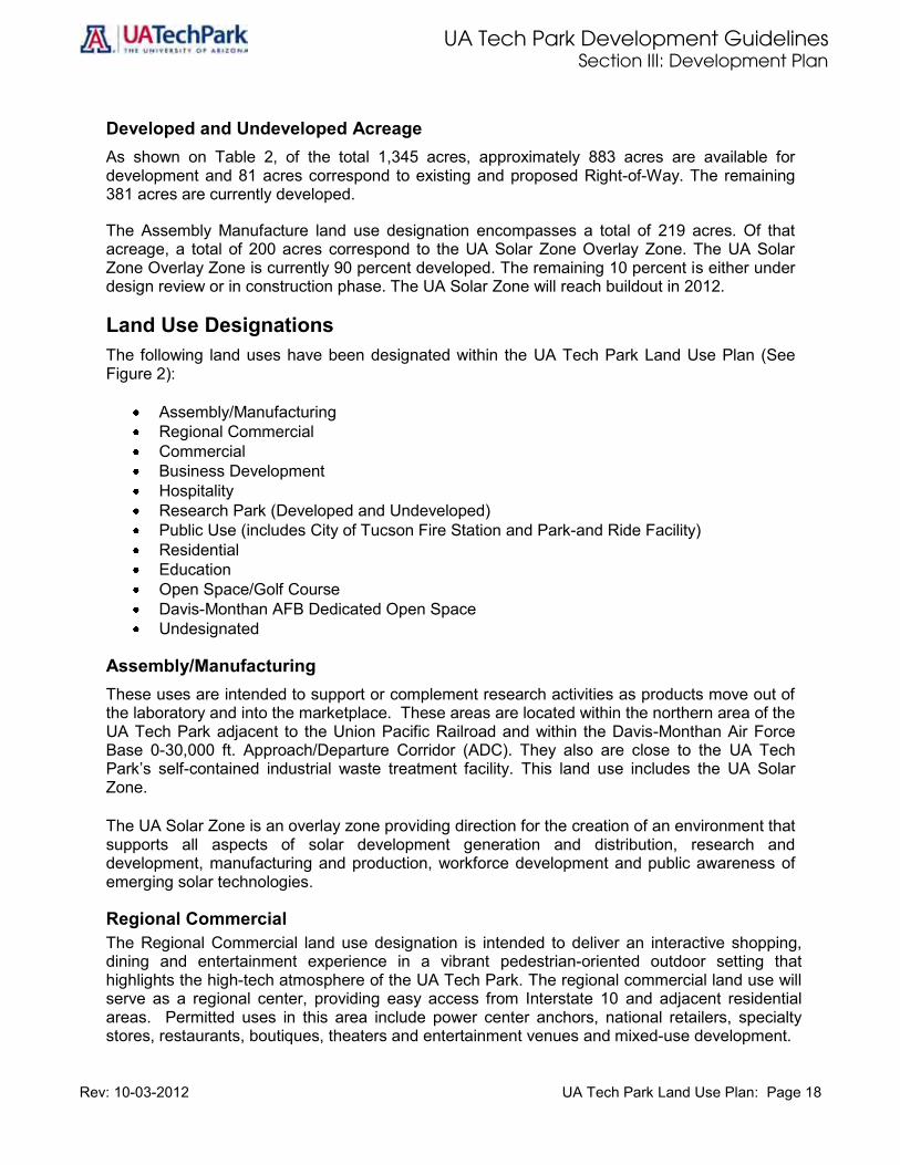
Developed and Undeveloped Acreage As shown on Table 2, of the total 1,345 acres, approximately 883 acres are available for development and 81 acres correspond to existing and proposed Right-of-Way. The remaining 381 acres are currently developed.
The Assembly Manufacture land use designation encompasses a total of 219 acres. Of that acreage, a total of 200 acres correspond to the UA Solar Zone Overlay Zone. The UA Solar Zone Overlay Zone is currently 90 percent developed. The remaining 10 percent is either under design review or in construction phase. The UA Solar Zone will reach buildout in 2012.
Land Use Designations The following land uses have been designated within the UA Tech Park Land Use Plan (See Figure 2):
Assembly/Manufacturing Regional Commercial Commercial Business Development Hospitality Research Park (Developed and Undeveloped) Public Use (includes City of Tucson Fire Station and Park-and Ride Facility) Residential Education Open Space/Golf Course Davis-Monthan AFB Dedicated Open Space Undesignated
Assembly/Manufacturing These uses are intended to support or complement research activities as products move out of the laboratory and into the marketplace. These areas are located within the northern area of the UA Tech Park adjacent to the Union Pacific Railroad and within the Davis-Monthan Air Force Base 0-30,000 ft. Approach/Departure Corridor (ADC). They also are close to the UA Tech Park’s self-contained industrial waste treatment facility. This land use includes the UA Solar Zone.
The UA Solar Zone is an overlay zone providing direction for the creation of an environment that supports all aspects of solar development generation and distribution, research and development, manufacturing and production, workforce development and public awareness of emerging solar technologies.
Regional Commercial The Regional Commercial land use designation is intended to deliver an interactive shopping, dining and entertainment experience in a vibrant pedestrian-oriented outdoor setting that highlights the high-tech atmosphere of the UA Tech Park. The regional commercial land use will serve as a regional center, providing easy access from Interstate 10 and adjacent residential areas. Permitted uses in this area include power center anchors, national retailers, specialty stores, restaurants, boutiques, theaters and entertainment venues and mixed-use development.

UA Tech Park Development Guidelines Section III: Development Plan
Rev: 10-03-2012 UA Tech Park Land Use Plan: Page 19
Commercial The Commercial land use designation is located outside of the main UA Tech Park campus west of I-10. Permitted uses in this area include general commercial and convenience uses serving the adjacent neighborhoods.
Business Development Business Development land use is suitable for the development of single- or multi-tenant typical class A and/or B facilities. These stand-alone/single-tenant and multi-tenant structures may serve as corporate headquarters and basic open space. Business support uses are allowed within this land use. Business Development uses are located within the Davis-Monthan Air Force Base 30,000-50,000 feet ADC.
Hospitality Hospitality uses allow for the development of a destination business-class hotel, with executive training conference center, hospitality casitas or villages, golf club house and support retail facilities adjacent to the 18-hole golf course, providing a variety of amenities to UA Tech Park tenants, visitors, and the surrounding community.
Research Park Research Park land uses are suitable for offices, science and laboratory space, educational facilities, and research facilities for high technology companies. These single-tenant and multi-tenant facilities accommodate the sophisticated needs and demands of a large variety of scientific and technology-based disciplines. This land use also provides space for the expansion needs of existing Research Park tenants. Affiliated uses are allowed within Research Park designated areas. Areas designated Research Park constitutes the research and development component of the UA Tech Park. The University of Arizona South will be located within this land use. This land use also includes a portion of the Solar Zone.
Companies locating within this area must be involved in the development or enhancement of technologies related to one of Southern Arizona’s industry clusters:
Optics/Photonics Information Technology Aerospace Environmental Technology Advanced Materials Life Sciences
In addition, companies must be willing to develop a working relationship with the University of Arizona. This relationship may include, but is not limited to:
Joint research projects, Use of University of Arizona students as interns or employees, Participation of company personnel in University teaching activities, boards or
committees, and/or Use of University facilities.

UA Tech Park Development Guidelines Section III: Development Plan
Rev: 10-03-2012 UA Tech Park Land Use Plan: Page 20
Public Use This land use consists primarily of public uses serving regional needs. This land use includes the City of Tucson Fire Station, located along Kolb Road at the northwest portion of the UA Tech Park adjacent to the Pima County retention facility and outside of the Davis-Monthan AFB ADC. This parcel of land will include governmental functions. This land use also includes a park and ride facility along Kolb Road at the northwest portion of the UA Tech Park. This park and ride facility provides access to the Park Shuttle service and includes access to the Julian Wash Trail Head, nature trails, hiking trails, and bicycle paths, providing connectivity to the UA Tech Park trail system and regional trail systems. Standards and guidelines for Park and Ride are provided in Section IV of this volume in Chapter E: Parking Lots and Parking Structures. Guidelines for trails and bicycle routes are provided in Section IV of this volume in the Open Space, Pedestrian and Bicycle Circulation and Circulation and Access chapters.
Residential Residential land use is suitable for the development of multi-family as well as detached and attached single-family residences, with densities up to zero-lot lines.
Education Education land use includes a K-12 academy and high school, preschool and child development center for the Vail School District. The Vail Academy and High School and Child Development Center will service the needs of the adjacent residential community, the existing Vail High School within the UA Tech Park and UA Tech Park tenants. Child care and school facilities are allowed within this land use. This land use is developed.
Open Space/Golf Course This land use includes an 18-hole golf course and utilizes the natural landscape setting to the greatest degree feasible while minimizing intrusion into the natural surrounding vegetation. This land use is compatible with Davis-Monthan AFB 0-30,000 ft. ADC. Development standards and guidelines for golf course are provided in Section IV of this volume in the Open Space Chapter.
Davis-Monthan AFB Dedicated Open Space Corridor In addition to the 25% minimum open space required at parcel level, the UA Tech Park designates 136 acres as the Davis-Monthan AFB Dedicated Open Space corridor. This corridor supports Davis-Monthan AFB flight operation. Open space systems ensure the preservation of the campus-like atmosphere of the site, provides for a mix of riparian habitat, naturally occurring washes, archaeological and cultural resources, and recreational uses such as the Julian Wash Regional Trail and linear park, recreational facilities and golf courses. Open space systems and pedestrian linkages or trails serve as the underlying connective development fabric for the UA Tech Park. Open space areas facilitate the preservation of environmentally sensitive areas and are integral to the UA Tech Park’s storm water management system.
UA Tech Park Development Guidelines Section III: Development Plan
Rev: 10-03-2012 UA Tech Park Land Use Plan: Page 21
The UA Tech Park Master Plan fulfills the University’s commitment to ensure that the site is user-friendly and to maintain the open, visually rich character of its campus. It also ensures that development will be sensitive to the UA Tech Park’s naturally occurring washes, riparian habitat and archaeological sites.
UA Tech Park Gateways and Signature Entry Boulevards In addition to land use designations and overlay zones, the UA Tech Park Land Use Plan identifies main gateways or signature entry boulevards. Signature entry features are located at the main gateways of these signature entry boulevards at the Kolb and Rita roads main entrances to the UA Tech Park. Signature Entry Boulevards are provided at the two main gateways to the UA Tech Park located at Kolb and Rita Roads. Policy direction for the development of signature entry boulevards is provided in Section IV of this volume in the Circulation and Access chapter.
UA Tech Park Overlay Zones There are four overlay zones directing development within the UA Tech Park. These are the UA Solar Zone, the low Intensity Office Overlay Zone, the UA Tech Park Center Overlay Zone and the UA Tech Park Plaza Overlay Zone. UA Solar Zone Overlay Zone The UA Solar Zone is an overlay zone providing direction for the creation of an environment that supports all aspects of solar development generation and distribution, research and development, manufacturing and production, workforce development and public awareness. Section IV of this document provides development standards and guidelines for development in this overlay zone.
The site is currently the largest multi-technology solar generating facility in the world. The existing multiple-technology solar fields are connected to the grid and deploy solar power for approximately 3,400 homes. Tucson Electric Power manages these facilities. Ongoing testing to determine the most efficient solar energy technologies is in place. The 200-acre site is 90 percent built and includes national and international leaders such as SOLON, Amonix, Rhenu Solar, AstroSol and AstroEnergy.
Low Intensity Office Overlay Zone The Low Intensity Office Overlay Zone is located north of Science Park Drive and overlays the Open Space/Golf Course land use designation. This overlay consists of three ten-acre office parcels that will function as professional centers designed to accommodate a mix of business, professional, research, services, and office uses, in a low intensity office environment seamlessly integrated with its surrounding open space/golf course. UA Tech Park Center Overlay Zone A floating overlay zone not delineated in the UA Tech Park Land Use Plan is the UA Tech Park Center Overlay Zone. This overlay zone provides specific guidelines for commercial-retail, and hospitality development along Kolb Road adjacent to the UA Tech Park hotel. This overlay zone will help define the Park Center or core bridging the Regional Commercial and Hospitality parcels, articulating the transition from public high-intensity uses to more private less-intensity resort uses.

UA Tech Park Development Guidelines Section III: Development Plan
Rev: 10-03-2012 UA Tech Park Land Use Plan: Page 22
This core will provide a focal gathering center for UA Tech Park users and visitors and will support the golf course and the golf course club house as well as adjacent conference center, hospitality development, retail, office, and residential uses.
The UA Tech Park Plaza A floating overlay zone not delineated in the UA Tech Park Land Use Plan is the UA Tech Park Plaza. The UA Tech Park Plaza or pedestrian mall is located adjacent to the developed Research Park. This land use will include walkways and bicycle access as well as landscaped amenities providing connectivity to the Rita Road signature entry or main gateway and the regional trail system. This form of open space is designed to define a destination with a distinguished character, to provide connectivity between Research Park and Business Development uses, to provide linkages to the UA Tech Park and the regional trail systems and to serve UA Tech Park users, tenants, visitors, and surrounding community.
UA Tech Park Activity Nodes Three major activity nodes are established at the UA Tech Park: the Kolb Road Activity Node; the Pantano Road Alignment Activity Node; and the Rita Road Activity Node.
Kolb Road Activity Node The activity node at Kolb Road, a main gateway to the UA Tech Park, encompasses a mixture of carefully designated medium- to high-intensity mixed uses appropriate for this area. This activity node will serve UA Tech Park users, visitors, and the region and includes: a 250-room destination hotel and a 210-room hotel; a conference center; 100 casitas or hospitality villas; a golf course; a golf club house; the Park Center; regional marketplace retail and office uses; the City of Tucson Fire Station; a recreation center; trail head access to the Julian Wash Regional Trail, the UA Tech Park trail system and the regional trail system; and a park and ride facility. This activity node is located in close proximity to adjacent residential areas and low-intensity office uses.
Pantano Road Alignment Activity Node The activity node at the Pantano Road alignment encompasses a mixture of carefully designated medium-intensity mixed uses appropriate for this area of the UA Tech Park. This activity node will respond to UA Tech Park tenants and residents living in adjacent residential areas and includes: the Vail Academy and High School; a child development center; the University of Arizona South Campus; the Science Park Drive Multi-Use Path; the Julian Wash Linear Park; the UA Solar Zone Gateway Center and a regional park. This activity node is located in close proximity to adjacent residential areas, low-intensity office, the UA Solar Zone and the Research Park.
Rita Road Alignment Activity Node The activity node at Rita Road, a main gateway to the UA Tech Park, encompasses a mixture of carefully designated medium-intensity mixed uses appropriate for this area of the Tech Park. This activity node will serve primarily Tech Park tenants, users, visitors, and surrounding areas and includes: business development, including corporate headquarters; research park uses; and support uses. This activity node is located in close proximity to the developed portion of the Research Park and includes YMCA facilities and its adjacent park.
Figure 3 shows UA Tech Park Activity Nodes and Overlay Zones.

UA Tech Park Development Guidelines Section III: Development Plan
Rev: 10-03-2012 Figure 3: UA Tech Park Activity Nodes and Overlay Zones: Page 23
Figure 3: UA Tech Park Activity Nodes and Overlay Zones

UA Tech Park Development Guidelines Section III: Development Plan
Rev: 10-03-2012 UA Tech Park Land Use Plan: Page 24
This page corresponds to back of the 11x17 graphic to keep correct pagination.
Do not include this page in the original document.
UA Tech Park Development Guidelines Section IV: General Guidelines (Non-Residential Development)
Rev: 10-03-2012 A. Site Planning: Page 25
Section IV: General Guidelines (Non-Residential Development)
Introduction
This section provides general development standards and design guidelines for non-residential development.
New non-residential development must comply with development precepts and policy direction provided in the UA Tech Park Master Plan. In addition to compliance with general development standards and design guidelines provided in this section, new non-residential development must comply with specific development guidelines provided in Section VI of this volume. New uses located inside the Ring Road within the Project Area will continue to follow the established guidelines for development in the Project Area. Guidelines for residential development are provided in Section V of this volume. Guidelines for the Science Park Drive Multi-Use Path are provided in Chapter C: Circulation and Access of this volume.
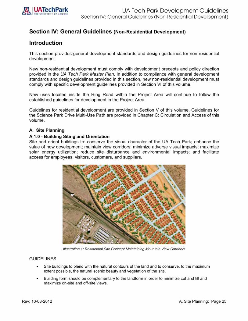
A. Site Planning A.1.0 - Building Siting and Orientation Site and orient buildings to: conserve the visual character of the UA Tech Park; enhance the value of new development; maintain view corridors; minimize adverse visual impacts; maximize solar energy utilization; reduce site disturbance and environmental impacts; and facilitate access for employees, visitors, customers, and suppliers.
Illustration 1: Residential Site Concept Maintaining Mountain View Corridors
GUIDELINES
Site buildings to blend with the natural contours of the land and to conserve, to the maximum extent possible, the natural scenic beauty and vegetation of the site.
Building form should be complementary to the landform in order to minimize cut and fill and maximize on-site and off-site views.

UA Tech Park Development Guidelines Section IV: General Guidelines (Non-Residential Development)
Rev: 10-03-2012 A. Site Planning: Page 26
Orient buildings to allow views through and into the UA Tech Park and to provide connections and visual access where possible to UA Tech Park trails, open spaces and view corridors.
Provide primary entrances that are immediately identifiable from the interior driveways and parking areas.
Provide secondary entrances that are conveniently accessible from parking and delivery areas.
Create interesting street scenes through varying building setbacks.
Create plazas, courtyard spaces and pedestrian walks through coordinated placement and orientation of buildings.
Maximize solar energy efficiency through building siting and orientation.
Site buildings so as to minimize the visual impact of parking areas.
A.2.0 –Coverage Requirements (Site, Lot, and Building Coverage) In general, the total amount of impervious surface (building, parking, driveways, etc.) will constitute no more than 55% of the total acreage of the UA Tech Park. The balance of the site should be common and private open space. At the individual parcel level, the maximum building coverage permitted in the UA Tech Park is 50% of the total gross lot area, unless specified otherwise in Section VI.2 Site coverage is the total amount of impervious surface (building, parking, driveways,
etc.) and constitutes no more than 55% of the total UA Tech Park acreage.
Lot coverage is the total amount of impervious surface (building, parking, driveway, etc.) at the individual parcel level divided by the total gross lot area. Maximum lot coverage is 50% unless specified otherwise in Section VI.
Building coverage is the total amount of land area covered by buildings (i.e., it does not include landscaped or recreation areas, covered patios, driveways, parking, etc.) at the individual lot or parcel level divided by the total gross lot area. Maximum building coverage is 30% without parking structure and 50% with parking structure unless specified otherwise in Section VI.
Site Coverage
Illustration 2: Site Coverage.
2 The City of Tucson does not have a maximum total building coverage for nonresidential uses located in nonresidential zones
(see City of Tucson Land Use Code, sections 3.2.1 and 3.2.9). Pima County permits only 33% total building coverage. Other standards permit 35% coverage of land uses without parking structures and 55% with parking structures.
UA Tech Park Boundary Open space Total amount of impervious surface (building, parking, driveways, etc.) limited to a maximum coverage of 55% of the total UA Tech Park gross land area.
55%

UA Tech Park Development Guidelines Section IV: General Guidelines (Non-Residential Development)
Rev: 10-03-2012 A. Site Planning: Page 27
Lot Coverage
Illustration 3: Lot Coverage.
Building Coverage
Illustration 4: Building Coverage. GUIDELINES
Limit site coverage or total amount of impervious surface (building, parking, driveways, etc.) to 55% of the total UA Tech Park acreage. The balance of the UA Tech Park will be common and private open space.
Limit lot coverage or total amount of impervious surface (building, parking, driveways, etc.) to 50% of the individual lot area unless specified otherwise in Section VI.
Limit building coverage to 30% of the lot gross land area unless specified otherwise in Section VI.
No more than 55% of the gross land area may be covered by a stand-alone parking structure.
The minimum amount of open space provided within each development parcel or cluster of parcels is 25% unless specified otherwise in Section VI. Open space can include areas such as landscape amenities, sidewalks, hardscapes, plazas and courtyards.
A.3.0 – Setback and Landscape Amenity Requirements Setbacks are established to create variation in the placement of buildings and parking lots along street frontages and to provide adequate spatial separation between adjoining uses. All buildings shall be set back from interior and perimeter roads to create areas for landscaping, sidewalks and other pedestrian pathways, entry features, monumentation, water features, signage and buffering between buildings, parking areas and streets.
Property line (individual parcel) Open space Building floor plate area or building footprint is limited to a maximum coverage of 30% of the total gross lot area without parking structure and 50% with parking structure.
30%
Property line (individual parcel) Open space Total amount of impervious surface (building, parking, driveways, etc.) limited to a maximum coverage of 50% of the total parcel or lot gross land area.
50%

UA Tech Park Development Guidelines Section IV: General Guidelines (Non-Residential Development)
Rev: 10-03-2012 A. Site Planning: Page 28
Setback distances of buildings within the UA Tech Park will differ depending on the land use, the type of building, and the location within the UA Tech Park. This section includes setbacks for non-residential development. Section V includes setbacks for residential development. Set back all non-residential buildings from interior and perimeter roads in conformance with the following guidelines.
GUIDELINES
Encourage Walkability by including sidewalks within setback areas.
Except for designated pedestrian routes in the Hospitality areas, convey a campus-like character from all major roadways.
Set back all buildings from interior and perimeter roads in sufficient dimensions to include landscape amenities between buildings, parking and the street.
Vary building setbacks to enhance visual interest.
Illustration 5: Example of Building Setback Including Landscape Amenities, Parkway, and Sidewalk.
A.3.1 – Interior Setback Establish appropriate interior setbacks as follows: GUIDELINES
Convey an urban, walkable, pedestrian-friendly character where the street sidewalks are inviting living routes for pedestrian access between employment, residential and retail uses, support services, and educational facilities.
Require a minimum front setback with street-side entries and parking on the side or in the rear of buildings along designated pedestrian routes and buildings.

UA Tech Park Development Guidelines Section IV: General Guidelines (Non-Residential Development)
Rev: 10-03-2012 A. Site Planning: Page 29
A.3.1.1 – Primary and Secondary Street Setbacks and Landscape Amenities Primary and secondary streets are defined in the Circulation and Access section of this document. Establish appropriate setbacks for primary and secondary streets as follows:
GUIDELINES
The Tech Park has adopted a minimum thirty feet (30’) landscape amenity area within the forty feet (40’) building setback.
The parkway area shall be a minimum of twelve (12’) feet in width. The parkway area is defined as the landscaped area separating the sidewalk from a vehicular lane.
The sidewalk area shall be a minimum of eight (8’) feet.
Traffic lanes, parkway area and sidewalk are parts of the right-of-way. The right-of-way begins at the property/parcel line.
Traffic Parkway Sidewalk 40’ Minimum Building Setback Lane 12’ 8’ with a 30’ minimum Landscape Amenity
Illustration 6: Building Setback and Landscape Amenity for Primary and Secondary Streets.
Parcel/Property Line or Right-of-Way

UA Tech Park Development Guidelines Section IV: General Guidelines (Non-Residential Development)
Rev: 10-03-2012 A. Site Planning: Page 30
A.3.1.2 – Internal Drive Frontage Building Setback and Landscape Amenity Require internal drives frontage building minimum setback for all buildings as follows:
GUIDELINES
Set back all buildings a minimum of one foot (1.0’) for every one foot (1.0’) of building height, but not less than forty feet (40’) from the property/parcel line or right-of-way line.
Landscape amenity areas within this setback shall be a minimum of ten feet (10’) in width with a fifteen feet (15’) minimum building perimeter landscape.
The sidewalk area shall be a minimum of eight (8’) feet in the Project Area and a minimum of six (6’) feet outside of the Project Area.
ROW Parkway Sidewalk Landscape Vehicular Lane Building Perimeter Varies 12’ 8’ Amenity Varies Landscape 10’ 15’
Illustration 7: Frontage Building Setback and Landscape Amenity for Internal Drives.
Parcel/Property Line or Right-of-Way

UA Tech Park Development Guidelines Section IV: General Guidelines (Non-Residential Development)
Rev: 10-03-2012 A. Site Planning: Page 31
A.3.1.3 – Internal Drive Side and Rear Building Setback and Landscape Amenity Require internal drives side and rear building minimum setback and include landscape amenities as follows:
GUIDELINES
Set back all buildings a minimum of ten feet (10’) from the property/parcel line.
Set back all buildings a minimum of fifteen feet (15’) from the parking or access driveway curb, and ten feet (10’) from the property/parcel or right-of-way line.
Landscape amenity areas within this setback shall be a minimum of five feet (5’) in width on either side of the property/parcel line, or a total of ten feet (10).
Parking or Access Driveway Landscape Amenity Building Setback (Varies) 10’ 10’
Illustration 8: Side and Rear Building Setback and Landscape Amenity for Internal Drive.
A.3.1.4 – Sidewalks, Crosswalks and Pedestrian Pathways within Setbacks GUIDELINES
Sidewalks and other pathways shall be provided throughout the UA Tech Park and along public roadways.
Crosswalks shall be provided at every major intersection and wherever appropriate (i.e., between integrated uses, between parking areas and buildings, and at all entrances/exits to the UA Tech Park).
Parcel/Property Line or Right-of-Way

UA Tech Park Development Guidelines Section IV: General Guidelines (Non-Residential Development)
Rev: 10-03-2012 A. Site Planning: Page 32
A.3.1.5 – Interior Setbacks in UA Tech Park Center Overlay Zone Pedestrian Routes Provide interior setbacks in UA Tech Park Center Overlay Zone pedestrian routes as follows:
GUIDELINES
Front setbacks should be established at a maximum of five feet (5’) from the edge of the sidewalk. Larger setbacks are allowed for arcades, patios, parks and plazas.
Parking in the UA Tech Park Center area should be located in the rear or on the side of buildings. If located in the side of the building, front setbacks should be established at a minimum of five feet (5’) with adequate screening and buffering including berms and landscaping.
A.4.0 – Utilities and Communication Devices All exterior on-site utilities such as water lines, gas lines, sewer and drainage systems, electrical and telephone wires and equipment must be installed and maintained underground, trenched, be in a spine, or be in a truss as indicated in the following guidelines.
GUIDELINES
Except in the Project Area where utilities may connect to the spine, all permanent utility lines should be installed underground.
Design and install utilities to minimize disruption of off-site activity during construction and maintenance.
Permit temporary overhead power and telephone facilities during construction only.
The developer should locate all data transmission and receiving telecommunication service in a central location. Individual roof-mounted or ground mounted data transmission and receiving installations are not permitted on individual parcels. Exceptions may be allowed where special user security or technical needs cannot be met with a central facility. In such a case, the following guidelines apply:
o Screen from view any devices for transmission or reception of communication signals.
o Maintain rooftop devices, to include, but not limited to, mechanical equipment, satellite dishes, platforms, and antennas below the building’s highest architectural elements so they are not visible within a horizontal line of sight.
o Screen ground-mounted devices from view from adjacent streets and properties and design them to integrate with the site with subdued use of colors that blend in with their surroundings.
Sound levels from transformers, air condenser units and other equipment should not exceed 5db at the property/parcel line.
All structures at ground level, such as manhole covers and grates, should be flush with the pavement to avoid tripping pedestrians. Grates should be spaced ½” or less to allow passage of bicycle and wheelchair tires.
A.5.0 – Service, Deliver and Storage Areas Screening Screenings are such things as vegetation, walls or other such structures that are used to conceal or minimize negative visual and auditory impacts of on-site activities and land uses from adjacent streets or development. The visual and auditory impact of utilities, data transmission dishes, transformers, and related facilities should be minimized in all development.

UA Tech Park Development Guidelines Section IV: General Guidelines (Non-Residential Development)
Rev: 10-03-2012 A. Site Planning: Page 33
To ensure a clean and orderly image within the UA Tech Park, locate and screen exterior elements such as utilities and communication devices, storage areas, loading/service areas, data transmission dishes, transformers, and related facilities that could cause undesirable visual and audio impacts to the environment in accordance to the following guidelines. GUIDELINES
Screen all transformers, switching boxes and other utility cabinets from view. Use plant materials or architectural screens. Avoid leaving meters exposed where visible to the public.
Locate transformers away from major pedestrian routes and outdoor seating areas, and screen them when feasible.
Accommodate all loading docks and service areas so that their impact to views from adjacent streets, properties, pedestrian pathways, and open space corridors are minimized.
Locate loading docks and service and delivery areas on the side or rear of a building or underground.
Locate loading docks and service and delivery areas so that they do not encroach into any setback area.
Locate parking areas for equipment trucks, research trailers and service vehicles away from public parking lots and major pedestrian circulation routes and screen them architecturally and with landscaping: o Screening for loading docks and service areas should be a minimum of six feet (6’) high,
noncombustible, and constructed of materials and finishes that harmonize with the main building.
o Store all materials, supplies, trucks and equipment inside a building or behind a visual barrier screen such that they are not visible from streets and adjacent properties. Visual barriers can be dense landscape screen or a combination of a wall with landscape materials.
o Clearly identify service entrances with signs to discourage use of the main entrances for deliveries.
o Locate air intakes away from loading docks or other areas where exhaust fumes from vehicles may be drawn into the building.
o Screen service entrances, air intakes, and loading decks as to prevent looking down into these areas from building windows.
Contain all refuse generated on-site in enclosures hidden from street frontages and adjacent properties. Located such enclosures in areas with convenient access for refuse vehicles.
Construct refuse enclosure walls with a minimum 6 feet in height, and of material and color similar or complementary to the adjacent buildings.
Locate necessary aboveground utilities, such as double detection check assemblies, behind the street hedge.
UA Tech Park Development Guidelines Section IV: General Guidelines (Non-Residential Development)
Rev: 10-03-2012 A. Site Planning: Page 34
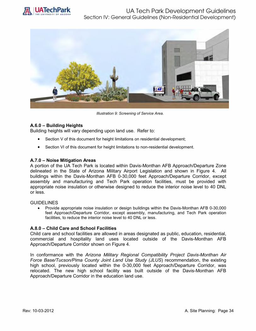
Illustration 9: Screening of Service Area.
A.6.0 – Building Heights Building heights will vary depending upon land use. Refer to:
Section V of this document for height limitations on residential development;
Section VI of this document for height limitations to non-residential development.
A.7.0 – Noise Mitigation Areas A portion of the UA Tech Park is located within Davis-Monthan AFB Approach/Departure Zone delineated in the State of Arizona Military Airport Legislation and shown in Figure 4. All buildings within the Davis-Monthan AFB 0-30,000 feet Approach/Departure Corridor, except assembly and manufacturing and Tech Park operation facilities, must be provided with appropriate noise insulation or otherwise designed to reduce the interior noise level to 40 DNL or less. GUIDELINES
Provide appropriate noise insulation or design buildings within the Davis-Monthan AFB 0-30,000 feet Approach/Departure Corridor, except assembly, manufacturing, and Tech Park operation facilities, to reduce the interior noise level to 40 DNL or less.
A.8.0 – Child Care and School Facilities Child care and school facilities are allowed in areas designated as public, education, residential, commercial and hospitality land uses located outside of the Davis-Monthan AFB Approach/Departure Corridor shown on Figure 4. In conformance with the Arizona Military Regional Compatibility Project Davis-Monthan Air Force Base/Tucson/Pima County Joint Land Use Study (JLUS) recommendation, the existing high school, previously located within the 0-30,000 feet Approach/Departure Corridor, was relocated. The new high school facility was built outside of the Davis-Monthan AFB Approach/Departure Corridor in the education land use.

UA Tech Park Development Guidelines Section IV: General Guidelines (Non-Residential Development)
Rev: 10-03-2012 A. Site Planning: Page 35
GUIDELINES
Locate childcare and school facilities in areas outside of the Davis-Monthan AFB Approach/Departure Corridor shown on Figure 4.
Locate childcare and school facilities within lands designated for residential and public/education development in the Tech Park Land Use Plan (Figure 2).
Locate school facility in close proximity to the Science Park Drive Multi-Use Path.
Provide school parcel connectivity with pedestrian walkways, nature trails, and bicycle paths.
The new Vail High School and Academy facility at the UA Tech Park is a LEED Platinum facility operated by wind and solar power located in the educational land use along Science Park Drive.
A.9.0 – Erosion and Sedimentation Control The UA Tech Park Master Plan requires that developers prepare an erosion and sediment control plan for the project site. Such plan will be reviewed by the UA Office of University Research Parks Design Review Committee as part of the Office of University Research Parks Development Review Process during the design stage and prior to construction and it must meet the following objectives:
1. Prevent loss of soil during construction by stormwater runoff and/or wind erosion, including
protecting top soil by stockpiling for reuse;
2. Prevent sedimentation of storm management facilities and washes; and
3. Minimize polluting the air with dust and particulate matter.

UA Tech Park Development Guidelines Section IV: General Guidelines (Non-Residential Development)
Rev: 10-03-2012 A. Site Planning: Page 36
GUIDELINES
Outline proposed measures and/or strategies, as part of the erosion and sediment control plan, to control erosion and to reduce negative impacts on water and air quality. Such measures and/or strategies may include, but not be limited to:
o temporary and permanent seeding;
o mulching;
o earth dikes;
o silt fencing;
o sediment traps; and
o sediment basins
Reduce the erosion effects of stormwater discharge, preserve the flood-carrying capacity of natural or constructed waterways by limiting soil loss, and protect drainageways from siltation.
Minimize dust pollution and erosion impacts on surface water drainage from graded areas during grading and development.
Provide erosion control devices to prevent erosion or sediment deposition on adjacent property.
Construct and maintain erosion control devices to prevent erosion of slopes, and cleared, brushed, grubbed or graded areas.
Protect shoulders of paved private or public roadways against erosion wherever curbing or constructed spillways are not provided.
Transport earth material on public or private roadways in a manner that minimizes blowing soil and other hazards.
Load and unload earth material within the hours of operation for grading equipment provided in A.10.0.
A.10.0 –Grading, Site Revegetation, and Stabilization The UA Tech Park Master Plan requires new development to comply with minimum standards or development guidelines for grading, site revegetation, and stabilization provided in this section and/or any other mitigation method recommended by a registered civil engineer which meets or exceeds local standards. For the purpose of this section, grading is defined as the clearing, brushing, grubbing, excavating, or filling on any development parcel or lot, or any portion thereof. GUIDELINES
Submit a grading sketch and/or grading plan during the design stage as part of the Office of University Research Parks Development Review Process for UA Office of University Research Parks Design Review Committee approval that demonstrates compliance with the following guidelines and/or standards:
o Design all grading to minimize adverse visual impacts resulting from cut and fill.
o Revegetate or stabilize all exposed cut or fill slopes.
o Ensure that graded slopes or other areas subject to erosion are stabilized.
o Provide surface drainage interceptors at the top of cut and fill slopes where there is surface runoff and erosion potential.

UA Tech Park Development Guidelines Section IV: General Guidelines (Non-Residential Development)
Rev: 10-03-2012 A. Site Planning: Page 37
o Ensure that development activity is designed and implemented to minimize adverse impacts and includes appropriate restorative measures.
o Minimize dust, during grading, and until revegetation or stabilization has taken place, through application of approved dust controls.
o Prohibit the driving of vehicles over natural open space areas not designated in the approved grading sketch or grading plan.
o Identify all points-of-entry to the site during grading in the grading sketch or grading plan.
o Maintain public rights-of-way, sidewalks and other improvements in a neat and clean condition, during construction free of loose soil, construction debris, and trash.
o Prohibit the storage of debris, fill, or equipment within a public right-of-way without UA Office of University Research Parks Design Review Committee approval.
o Limit the hours of operation of grading equipment within one-half mile of a structure occupied by humans and/or the operation of equipment maintenance involving lights, motors or generators, and occurring within six hundred feet of a structure occupied by humans from 7 a.m. to 9 p.m.
o Provide a minimum setback of one fifty of the vertical height of cut, with a minimum of two feet and a maximum of ten feet for top of cut slopes, measured from the lot boundary line.
o Provide a minimum setback of one-half the height of the slope, with a minimum of two feet and a maximum of twenty feet for tow of fill slope, measured from the lot boundary line.
University of Arizona Office of University Research Parks, UA Tech Park

UA Tech Park Development Guidelines Section IV: General Guidelines (Non-Residential Development)
Rev: 10-03-2012 A. Site Planning: Page 38

UA Tech Park Development Guidelines Section IV: General Guidelines (Non-Residential Development)
Rev: 10-03-2012 Figure 4: Davis-Monthan Air Force Base Approach/Departure Corridor: Page 39
Figure 4: Davis-Monthan Air Force Base Approach/Departure Corridor
UA Tech Park Development Guidelines Section IV: General Guidelines (Non-Residential Development)
Rev: 10-03-2012 B. Stormwater Management/Drainage: Page 40
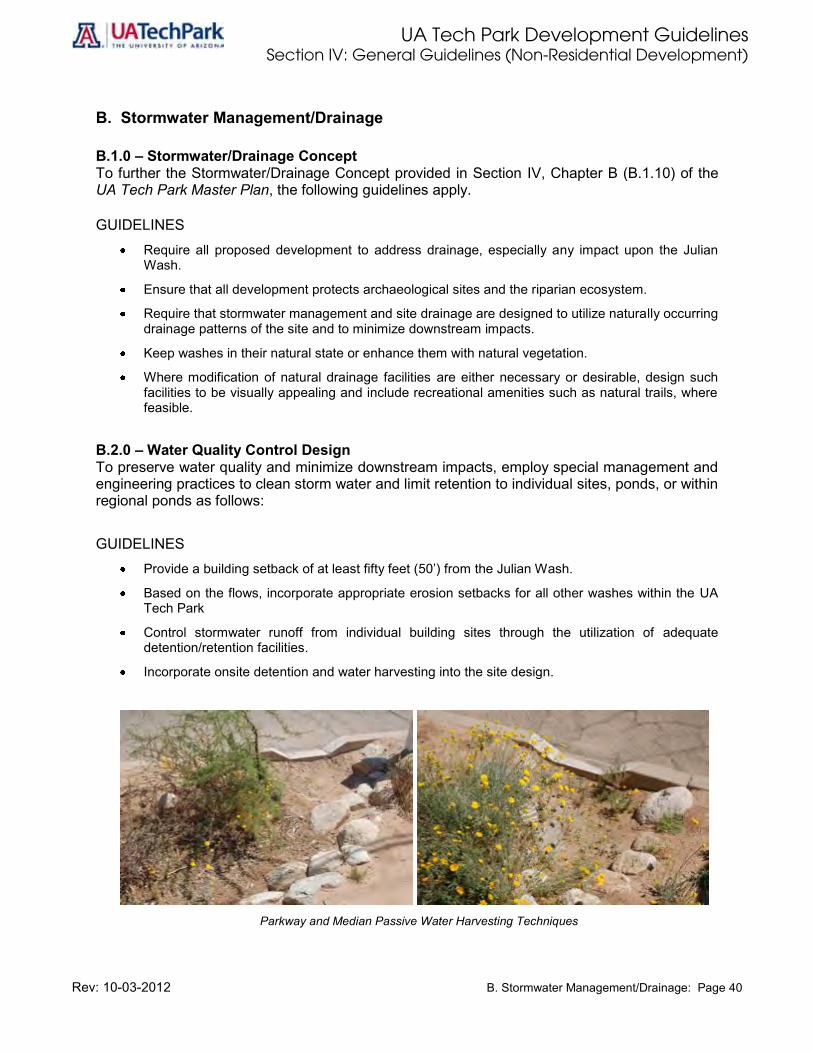
B. Stormwater Management/Drainage
B.1.0 – Stormwater/Drainage Concept To further the Stormwater/Drainage Concept provided in Section IV, Chapter B (B.1.10) of the UA Tech Park Master Plan, the following guidelines apply.
GUIDELINES
Require all proposed development to address drainage, especially any impact upon the Julian Wash.
Ensure that all development protects archaeological sites and the riparian ecosystem.
Require that stormwater management and site drainage are designed to utilize naturally occurring drainage patterns of the site and to minimize downstream impacts.
Keep washes in their natural state or enhance them with natural vegetation.
Where modification of natural drainage facilities are either necessary or desirable, design such facilities to be visually appealing and include recreational amenities such as natural trails, where feasible.
B.2.0 – Water Quality Control Design To preserve water quality and minimize downstream impacts, employ special management and engineering practices to clean storm water and limit retention to individual sites, ponds, or within regional ponds as follows:
GUIDELINES
Provide a building setback of at least fifty feet (50’) from the Julian Wash.
Based on the flows, incorporate appropriate erosion setbacks for all other washes within the UA Tech Park
Control stormwater runoff from individual building sites through the utilization of adequate detention/retention facilities.
Incorporate onsite detention and water harvesting into the site design.
Parkway and Median Passive Water Harvesting Techniques
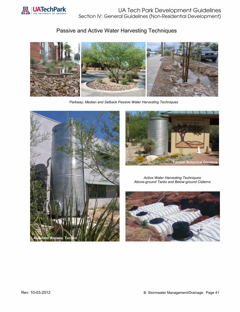
UA Tech Park Development Guidelines Section IV: General Guidelines (Non-Residential Development)
Rev: 10-03-2012 B. Stormwater Management/Drainage: Page 41
Passive and Active Water Harvesting Techniques
Parkway, Median and Setback Passive Water Harvesting Techniques
Active Water Harvesting Techniques
Above-ground Tanks and Below-ground Cisterns
Tucson Botanical Gardens
Audubon Society, Tucson

UA Tech Park Development Guidelines Section IV: General Guidelines (Non-Residential Development)
Rev: 10-03-2012 B. Stormwater Management/Drainage: Page 42
B.3.0 – Drainage Criteria GUIDELINES
Design onsite drainage to minimize water collection at building foundations, entrances and service areas.
Prohibit the use of dry wells. Incorporate natural trails adjacent to drainage pathways along riparian areas.
Illustration 10: Conceptual Cross-Section for Drainage and Trails within Riparian Areas.
B.4.0 – Detention/Retention GUIDELINES
Use detention and retention ponds to drain sites, buildings and parking lots.
Design detention areas with a natural appearance and seed them with native vegetation, with the exception of detention areas within golf courses.

UA Tech Park Development Guidelines Section IV: General Guidelines (Non-Residential Development)
Rev: 10-03-2012 C. Circulation and Access: Page 43
C. Circulation and Access
C.1.0 – Vehicular Circulation Concept Safe, convenient vehicular circulation is a distinct feature of the UA Tech Park Master Plan. Vehicular access and circulation is achieved through a series of primary and secondary roads within the UA Tech Park (See Figure 2). Science Park Drive is the primary road or arterial providing east-west access to the UA Tech Park. Although only a portion of Science Park Drive has been developed, this arterial road will extend from the Kolb Road to the Rita Road main gateways or signature entries of the UA Tech Park. The Science Park Drive proposed alignment is shown in Figure 2. Science Park Drive will provide two access points into the UA Tech Park along Kolb Road: a signalized signature entry; and a secondary entry with right-in and right-out only. Signature entry boulevards provide access via signature entry features to the UA Tech Park at those points indicated on Figure 2. Signature entry features are located at Rita Road and Kolb Road. The purpose of these signature entry features is to provide a distinct place-making identity and sense of arrival to a world-class destination, the UA Tech Park. Currently, the primary UA Tech Park entry is located along Rita Road. A signature entry is proposed south of the existing Rita Road entry, which currently provides direct access to Buildings 9040 and 9060. The new signature entry will provide access into the UA Tech Park near the southern end of the pedestrian/utility spine and building 9070. Secondary roads feed off of primary roads and provide access to development areas. Secondary entrances provide access to Business Development, Residential, Assembling/Manufacturing, and Research Park land uses and the Solar Zone. Illustrations 12 and 13 show cross-sections for primary and secondary roads. Internal secondary entry features provide access points to residential and Research Park areas at the intersection of primary and secondary roads. Coordinated landscaping along signature entry boulevards, primary and secondary roads, and at driveway entrances is required. The UA Tech Park Plaza or pedestrian mall provides a pedestrian-oriented streetscape and connectivity between Research Park and adjacent support uses. The primary goal of the vehicular circulation concept is to ensure safe, convenient and efficient multimodal circulation and access through the establishment of a functional hierarchy of streets designed to serve current and future UA Tech Park needs. This chapter provides cross-sections for primary and secondary access roads and guidelines for signature entry boulevards, signature entry features, secondary entry features and the UA Tech Park Plaza or pedestrian mall.

UA Tech Park Development Guidelines Section IV: General Guidelines (Non-Residential Development)
Rev: 10-03-2012 C. Circulation and Access: Page 44
C.2.0 – Street Hierarchy There is a functional hierarchy to streets and drives in the UA Tech Park. This hierarchy is expressed in the street design and landscape treatment along the street. The street categories are:
a. Primary Roads: The main spine roads or arterials providing access to and through the
UA Tech Park. Minimum road right-of-way is 120 feet and should be developed in accordance to Illustration 18.
b. Secondary Roads: Roads that feed off of primary roads and that provide access into individual development clusters. Minimum road right-of-way is 70 feet and should be developed in accordance to Illustration 13.
c. Internal Drives: A road shared by more than one user for access to building parcels.
d. Entrance Drive: A road providing access to individual building drop-off and parking areas.
e. Service Drive: A road providing access to loading and waste pick-up areas.
f. Pedestrian Street: Pedestrian mall within the UA Tech Park Plaza designed to foster an inviting and convenient setting for pedestrian travel. The UA Tech Park Plaza provides connectivity to different facilities within the Research Park, surrounding support services and adjacent development.
C.3.0 – Tech Park Gateways and Entryways Develop a hierarchy of entrances to the Tech Park in accordance with the following guidelines, making it obvious to UA Tech Park visitors which entrance they should use.
GUIDELINES
Distinguish main UA Tech Park entrances from secondary entrances.
Provide signature entry features that convey a strong sense of arrival at the Kolb and Rita Road main entrances to the UA Tech Park.
Provide multi-modal signature entry boulevards at the Kolb and Rita Road entries to the UA Tech Park.
Provide secondary entry features at the intersection of primary and secondary roads and at secondary entrances to the UA Tech Park as shown on Figure 2.

UA Tech Park Development Guidelines Section IV: General Guidelines (Non-Residential Development)
Rev: 10-03-2012 C. Circulation and Access: Page 45
Illustration 11: Rita Road Multimodal Access Conceptual Gateway and Signature Entry Feature
C.3.1 – Signature Entry Boulevards Provide signature entry boulevards at the Kolb Road and Rita Road entries to the UA Tech Park shown in Figure 2 in accordance with the following guidelines:
GUIDELINES
Require that multimodal signature entry boulevards convey a sense of arrival and provide a place-making identity designed to enhance visitors and users experience as they travel to and from the UA Tech Park.
Enhance signature entry boulevards with plant materials and street furniture typical of more urban settings. More attention to detail, colors, shapes and textures should be made, providing for greater varieties of plant materials than available on primary and secondary roadways.
Design signature entry boulevards to minimize conflicts between different modes and provide connectivity to adjacent uses.
Provide a visitors center with access to Commercial and Hospitality areas and the signature entry boulevard at Kolb Road.
Employ a landscape theme that is consistent with the UA Tech Park’s overall landscape theme of native vegetation and riparian environment.
Utilize decorative paving patterns with varying natural colors to accentuate the vehicular, pedestrian and bicycle entries.
Illustration 12: Signature Entry Boulevards Showing Decorative Paving Patterns.

UA Tech Park Development Guidelines Section IV: General Guidelines (Non-Residential Development)
Rev: 10-03-2012 C. Circulation and Access: Page 46
C.3.2 – Signature Entry Features Provide signature entry features at Kolb and Rita Road entries to the UA Tech Park shown in Figure 2: UA Tech Park Land Use Plan in accordance with the following guidelines.
GUIDELINES
Utilize landscape features such as monument walls, lighting, ornamental plantings and signage that convey a sense of arrival to the UA Tech Park at signature entries.
Ensure that safety visibility triangles are provided at signature entry points.
Employ a landscape theme that is consistent with the UA Tech Park’s overall landscape theme of native vegetation and riparian environment.
Utilize decorative paving patterns with varying natural colors to accentuate vehicular, bicycle and pedestrian entry points.
Illustration 13: Example of Monumentation, Plant Palettes and Decorative Paving at a Signature Entry Feature, UA BioPark, Tucson, Arizona

UA Tech Park Development Guidelines Section IV: General Guidelines (Non-Residential Development)
Rev: 10-03-2012 C. Circulation and Access: Page 47
C.4.0 – Design Character of Roadways and Entries Provide a strong and continuous place making identity along Science Park Drive, the east-west primary road or arterial connecting Kolb Road and Rita Road signature entry features or main gateways to the UA Tech Park and the Regional Commercial and Hospitality areas, identify ways to enhance visitors’ experience through the utilization of native streetscapes and public art, and provide a consistent campus-like design treatment of roadways and intersections throughout the UA Tech as follows:
GUIDELINES
Plant Palo Verde trees along Science Park Drive from the Kolb Road to the Rita Road entrances to the UA Tech Park.
Promote the Palo Verde Festival during Palo Verde blooming season to enhance visitors’ experience.
Enhance the intersection of entrance drives to development clusters and the primary entries to individual parcel/buildings with signs, accent paving, special landscaping and lighting. Secondary entrances to individual parcels/buildings should have a similar design treatment, although the intensity of landscape may be reduced.
Enhance all primary and secondary roadways with native plant materials listed in the streetscape plant list provided in Appendix A.
Consider roadway speeds and sightlines when selecting planting designs, plant materials, and spacing.
Provide pedestrian and bicycle friendly plant materials in areas where bicycle lanes and sidewalks occur.
Prohibit the use of cacti within three (3’) feet of sidewalks and bicycle lanes.
Enhance roadways in the Tech Park Center area with plant materials and street furniture typical of more urban settings. More attention to detail, colors, shapes and textures should be made, providing for greater varieties of plant materials than available on primary and secondary roadways.
Limit entrances to primary and secondary roadways in order to minimize congestion and conflicts.
Where possible, entrances into development clusters should occur off of secondary roadways.
Provide one (1) access point per every one hundred (100) parking spaces needed.
Entry roads and drives should provide unobstructed sight lines and dimensions for safe entering and exiting movements.
C.4.1 – Secondary Entry Features Provide secondary entry features at secondary entrances to the UA Tech Park and at the intersection of primary and secondary roads.
GUIDELINES
Secondary entry features at the entrances to Research Park and Solar Zone areas should convey a Tech Park look and provide a sense of identity for Tech Park and the Solar Zone.
Secondary entry features at the entrance of residential areas should serve to discourage through traffic and provide a sense of arrival to residential areas or residential neighborhoods.
Provide more intimate monumentation and landscape themes at the entry points to residential neighborhoods, school, and high school.
Entry to Assembly/Manufacturing areas should serve the user needs of that area.

UA Tech Park Development Guidelines Section IV: General Guidelines (Non-Residential Development)
Rev: 10-03-2012 C. Circulation and Access: Page 48
Illustration 14: Secondary Entry Feature - Science Park Drive Residential Entrance Showing Multimodal Access
Illustration 15: Secondary Entry Feature - Science Park Drive Vail High School and
Academy Entrance Showing Multimodal Access

UA Tech Park Development Guidelines Section IV: General Guidelines (Non-Residential Development)
Rev: 10-03-2012 C. Circulation and Access: Page 49
Illustration 16: Secondary Entry Feature - Science Park Drive Commercial
Entrance Showing Multimodal Access
C.5.0 – Drop-off Areas Incorporate safe and convenient passenger drop-off areas in all projects in conformance with the following guidelines.
GUIDELINES
Provide a separation between driveway curb and drop-off areas to minimize turning conflicts.
Provide a clear separation of vehicular traffic between drop-off zones and access to either a parking lot or parking structure.
Design drop-off lanes so as not to obstruct traffic flow when motorists are stopped to discharge passengers.
Use textured paving material that is distinguishable from the travel lane at the drop-off area and use signs to indicate “drop-off zone” or “passenger loading only.”

UA Tech Park Development Guidelines Section IV: General Guidelines (Non-Residential Development)
Rev: 10-03-2012 C. Circulation and Access: Page 50
C.6.0 – Vehicular Access/Driveways Locate access points on each development parcel to maximize traffic flow efficiency and minimize the disruption of street-side landscaping in conformance with the following guidelines.
GUIDELINES
Share driveways where possible. Provide at least 150 feet of separation between access points at major streets and appropriate
separation between access points at internal streets. Coordinate access points to correspond with median openings. Right turn only in/out access
shall be provided where no median openings exist. Where the driveway connects to a secondary road, a minimum distance of 50 feet from curb
return to edge of right-of-way at the intersection shall be maintained. Where a driveway connects to a primary road, a minimum distance consisting of the left turn
stacking distance plus 20 feet as measured from curb return to curb return, shall be maintained. The left turn stacking distance shall be determined by a Traffic Engineer based on available data from an acceptable traffic study.
Provide one (1) access point per every one hundred (100) parking spaces needed.
C.7.0 – Science Park Drive Multi-Use Path (Circulation and Access) The Science Park Drive Multi-Use Path supports Davis-Monthan AFB flight operations, UA Tech Park users, and adjacent residential and school development. As part of the UA Tech Park’s circulation and access system, this multi-use path serves as a major open space corridor linking open spaces, recreation facilities, the golf course, the UA South Campus, Vail Academy and High School, the UA Solar Zone, Research Park, and other uses. The corridor encompasses recreational uses such as paths, nature trails, and bike routes. Incompatible uses may result from differing speeds, path surface needs, or volume of users. It is important to provide separate trails, each tailored to the unique needs of a use mode or group of use modes. Bicycle and pedestrian users have different requirements for path surface. If traffic volume on a trail is high, dangerous conflicts can occur. For these reasons, the multi-use path should be split into separate path facilities for these user groups. The greatest potential safety hazard to path users is when a path crosses a roadway, railroad, wash, or another trail. The best way to increase safety is to increase visibility. It is important that crossings are visible both to path users and to motorized vehicles. There are two types of crossing: at-grade and grade separated. Grade separated crossing are recommended for high-volume areas along primary roadways. At-grade crossings are appropriate where motorized traffic volumes are low or local conditions prohibit grade separation. The Multi-use path should be designed to minimize conflicts and safety hazards and to promote user safety in accordance with the following guidelines.
GUIDELINES
Design separate path facilities for bicycle and pedestrian users.
Design each path facility wide enough to permit users to travel in both directions.
Provide a clear zone of two (2) feet or greater between bicycle and pedestrian path.
Maintain a clear zone of two (2) feet from each trail to any fence or tree.
Develop accessible pedestrian facilities that meet the needs of older adults and people with disabilities.

UA Tech Park Development Guidelines Section IV: General Guidelines (Non-Residential Development)
Rev: 10-03-2012 C. Circulation and Access: Page 51
Paths should cross roadways at right angles. In cases where paths approach the roadway at a skew, the trail should be routed to achieve a right-angle crossing wherever possible.
Use at-grade crossings when roadway traffic volumes are low, where paths cross roadways at existing traffic signals, or when local conditions restrict the ability to implement a grade-separated crossing.
Maintain appropriate sight lines for motorists and path user to be able to see each other at roadway crossings. A motorist needs to be able to stop in time if a path user is in the road, and a path user needs to be able to judge ability to cross the street safely.
Employ signage, stripping or pavement markings, and/or signals in varying degrees depending on hierarchy or functional classification and traffic volume of the roadway to be crossed to announce the crossing for both path users and motorists.
Base signage on the Federal Highway Administration (FHWA) Manual on Uniform Traffic Control Devices.
Place signage outside the recommended clear zones for both paths and roadways.
Design crossings of primary roads to include crossings at signal only, paving markings for crosswalks and bike routes, and cautionary and regulatory signage on the paths.
Design crossings of secondary roads to include crossings at signals, at controlled intersections, or mid-block with flash lights, paving markings for crosswalks and bike routes, cautionary and regulatory signage on the paths, and cautionary signage on roadway.
Design crossings of residential streets to include cautionary and regulatory signage on the paths, cautionary signage on roadway and paving markings for crosswalks if the path or roadway traffic volume is high, or if safety concerns exist.
When bicycle lanes intersect roadways, they should be regulated by the traffic control devices installed at the intersection.
Design rest areas such as interpretive areas or overlooks along the Science Park Drive Multi-Use Path. Such rest areas should at least include a seating area and a place to park bicycles. Rest areas may also include drinking water, restroom facilities, and signage
Interpretive facilities should include signage with ample graphics, to engage users of all ages. Place these facilities wherever there are significant cultural, historical, or natural resources.
Include directional signs with trail names, direction arrows, mileage to points of interest, and other relevant information where they will be clearly visible.
Illustration 17: Science Park Drive Showing Multi-Use Path

UA Tech Park Development Guidelines Section IV: General Guidelines (Non-Residential Development)
Rev: 10-03-2012 C. Circulation and Access: Page 52
6’ Bicycle Lane
12’ Travel Lane
13’ Travel Lane
20’ Landscaped Median (Water Harvesting)
13’ Travel Lane
12’ Travel Lane
6’ Bicycle Lane
Landscaped Area/Water Harvesting (Varies)
12’ Meandering
Multi-Use Path
Illustration 18 (a): Primary Road Cross-Section

UA Tech Park Development Guidelines Section IV: General Guidelines (Non-Residential Development)
Rev: 10-03-2012 C. Circulation and Access: Page 53
120’ R.O.W. 35’ Multi-Use Path
Illustration 18 (b): Primary Road Cross-Section

UA Tech Park Development Guidelines Section IV: General Guidelines (Non-Residential Development)
Rev: 10-03-2012 C. Circulation and Access: Page 54
8’ Sidewalk
12’ Landscape Area/ Water Harvesting
4’ Bicycle Lane
24’ (Two 12’ Travel Lanes)
4’ Bicycle Lane
12’ Landscaped Area/ Water Harvesting
8’ Sidewalk
Illustration 19 (a): Secondary Road Cross-Section
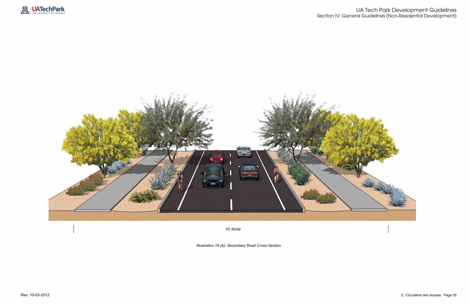
UA Tech Park Development Guidelines Section IV: General Guidelines (Non-Residential Development)
Rev: 10-03-2012 C. Circulation and Access: Page 55
Illustration 19 (b): Secondary Road Cross-Section
70’ ROW

UA Tech Park Development Guidelines Section IV: General Guidelines (Non-Residential Development)
Rev: 10-03-2012 C. Circulation and Access: Page 56
C.8.0 – Emergency and Utility Access Emergency vehicles should be able to reach the building on clearly designated routes as provided in the following guidelines.
GUIDELINES
Provide access for fire, police, ambulance and other emergency vehicles to all sides of the building.
Meet all Arizona State Fire Marshal regulations in the design of emergency access to buildings. Provide unobstructed access to all utilities (manholes, etc.) Avoid the creation of “blind areas” that cannot be patrolled by police or security staff.
C.9.0 – Mass Transit/Alternate Modes Continue to encourage the use of the SunTran public transportation system and the incorporation of a University or Park-operated shuttle service with convenient access throughout the UA Tech Park in conformance with the following guidelines.
GUIDELINES
Provide a consistent design for bus shelters that incorporates the image and identity of the UA Tech Park.
Locate bus shelters near major activity centers of the UA Tech Park and employment generating areas along primary and secondary roads.
Provide appropriate lighting for bus shelters. Provide pull out lanes for buses. Design bus shelters to provide shade and protection from inclement weather. Incorporate “high-tech” bus schedule displays where possible.
C.10.0 – Energy Conservation and Air Quality Encourage alternative modes of transportation for employees as a way of reducing the number of single-occupancy vehicles (SOV) trips to and from the site as well as reducing the amount of parking required on the site in conformance with the following guidelines. GUIDELINES
All employers are encouraged to offer incentives that promote the reduction of SOV trips, such as offering preferential parking to employees who ride share or who participate in a van pooling program.
All employers are encouraged to provide flexible, staggered work hours to reduce the short-term high concentration of pollutants during the peak commuting hours.
Provide bicycle lanes along primary and secondary roadways. Connections between on-street and off-street bicycle paths should be clear and consistent.
All employers are required to participate in the Pima Association of Governments travel reduction programs.
Provide charging stations for electric vehicles.
C.11.0 – Restricted Access Drives Security checkpoints may be necessary for some users to monitor access to a site or to individual buildings. Guard houses and gates should be located to be as visually unobtrusive as possible in conformance with the following guidelines.

UA Tech Park Development Guidelines Section IV: General Guidelines (Non-Residential Development)
Rev: 10-03-2012 C. Circulation and Access: Page 57
GUIDELINES Provide electric traffic control gates in locations where restricted entry is desirable. Furnish queuing space for cars waiting to enter or leave security control areas. Queuing area must be long enough so as to not interfere with the nearest intersection at peak
hours. Locate check points in areas that minimize crossing conflicts with major bicycle and pedestrian
routes where queuing vehicles may restrict visibility or cause hazardous conditions. Consider using contrasting pavement designs to identify stopping areas at check points.
C.12.0 – Equestrian Trails Equestrian trails are permitted within lands designated Davis-Monthan AFB Dedicated Open Space and north of Science Park Drive, the east-west spine road or primary arterial road. Equestrian trails must comply with the following guidelines.
GUIDELINES
Design separate trail facilities for equestrian users. Design equestrian trails wide enough to permit users to travel in both directions. Provide a clear zone of two (2) feet or greater between equestrian trails and bicycle and
pedestrian routes and trails. Provide a vegetated buffer between bicycle/pedestrian and equestrian trails with a planted
median separating equestrian trails from other trail modes. Maintain a clear zone of two (2) feet from each equestrian trail to any fence or tree. At-grade equestrian crossings are prohibited. Include directional signs with trail names, direction arrows, mileage to points of interest, and other
relevant information where they will be clearly visible.

UA Tech Park Development Guidelines Section IV: General Guidelines (Non-Residential Development)
Rev: 10-03-2012 D. Pedestrian and Bicycle Circulation: Page 58
D. Pedestrian and Bicycle Circulation A unique feature of the UA Tech Park is its integration of pedestrian and bicycle systems. The Julian Wash area and other natural open spaces within the UA Tech Park were planned to include pedestrian and bicycle pathways connecting the various development areas. These circulation routes are recreational amenities and alternatives to automobile circulation. D.1.0 – Overall Pedestrian and Bicycle Circulation All pedestrian spaces and routes shall be designed to invite walking throughout the UA Tech Park. Pedestrian and bicycle routes shall be integrated to form a comprehensive circulation system, with convenient access provided between development areas of the UA Tech Park in conformance with the following guidelines. GUIDELINES
Provide safe and well-identified connections to the primary pedestrian and bicycle paths within the UA Tech Park in the design of the pedestrian circulation system within each development area and within each building parcel.
Provide pedestrian links to common open space areas and connections to recreational facilities within the UA Tech Park.
Delineate areas of intense pedestrian activity with such features as accent pavement, landscaping, water features and specialty lighting, where feasible.
Enhance public pathways and open spaces in central areas with features, such as plazas, seating and fountains to invite pedestrians.
Direct the pedestrian traffic to the north side of structures to increase the amount of shading for the pathways, where feasible.
Locate bicycle parking adjacent to the pathways. Separate bicycle and pedestrian paths from each other and design them to minimize conflicts
with vehicular traffic. Develop primary and secondary road networks in a manner that allows bicycle and pedestrians to
co-exist with vehicles. Develop separate bicycle and pedestrian trails as well as paths through the open space corridors
that are dedicated to pedestrians and bicycle use only, provided that bicycle paths do not conflict with pedestrian trails and walkways.
Connect bicycle and pedestrian trails and paths to regional trials and paths. Establish adequate separation between access points.
D.1.1 –Bicycle System The bicycle system at the UA Tech Park includes bike lanes along primary and secondary roads and an integrated system of bicycle routes and pathways connecting the various development areas. Bicycle lanes and routes should be integrated to form a comprehensive circulation system, with convenient access provided between development areas. Provide pedestrian and bicycle access for both transportation and recreational purposes in conformance with the following guidelines.

UA Tech Park Development Guidelines Section IV: General Guidelines (Non-Residential Development)
Rev: 10-03-2012 D. Pedestrian and Bicycle Circulation: Page 59
GUIDELINES Alternative Mode – Recognize bicycle travel as a viable mode of travel to and within the UA
Tech Park. Provide the bicycle infrastructure necessary to attract bicycle use as an alternative to auto circulation and parking.
Off-Park Connections – Coordinate with the City of Tucson and Pima County to provide connectivity to City and County bike routes and lanes. This includes bicyclist activated signals at arterial street intersections.
Park Circulators – Provide striped bicycle lanes along primary and secondary streets, and bike trails along washes creating a park-wide network for bicycle circulation.
Bicycle Paths – Develop bicycle paths for high- and medium-volume situations or where street conditions require.
Joint Usage – Design major bicycle paths in some locations to double as fire lanes and possible shuttle routes. The two most typical situations of joint usage are at grade-separated arterial street crossings, and within Tech Park streets.
Bicycle/Pedestrian Conflicts – Design separate bicycle and pedestrian paths. For major open space areas, designate bicycle-free zones with perimeter bicycle parking.
Bicycle/Auto Conflicts – Design separate bicycle and auto lanes within roadways or separated bicycle paths where volumes warrant. At circulator street crossings utilize special crossing treatments. For arterial street crossings, provide grade-separated bicycle crossings where feasible.
Bicycle Parking – Provide sufficient bicycle parking in close proximity to buildings and open space destinations. Design parking areas in conformance to the guidelines provided in D.2.0. Bicycle Parking.
D.2.0 –Bicycle Parking There are many types of bicycle racks and lockers available. Some are suitable for certain situations but not others, and some designs are unsuitable anywhere. These Development Guidelines distinguish two general categories of bicycle parking, depending on use class: Short-term (Class II) Parking is needed where bicycles will be left for short stops. It requires a high degree of convenience (as close to destinations as possible). At least some short-term bicycle parking should be protected from the weather (a portion can be unprotected, since demand tends to increase during dry weather). Short term Class II bicycle parking provides shoppers, customers, messengers, and other visitors who generally park for two hours or less a convenient and readily accessible place to park bicycles. GUIDELINES
Locate short-term (Class II) bicycle parking within the following areas: o Areas designated for retail, commercial, convenience, and support service uses; o Areas within or adjacent to key pedestrian activity; and o Recreation areas located throughout the Tech Park.
Locate short-term (Class II) bicycle parking within 50 feet of the building entrance. Where there is more than one building on one site, or where building has more than one main
entrance, the parking must be located and or distributed to serve all buildings and all entrances. If more than 10 spaces are required, at least 50% should be covered.

UA Tech Park Development Guidelines Section IV: General Guidelines (Non-Residential Development)
Rev: 10-03-2012 D. Pedestrian and Bicycle Circulation: Page 60
Long-term (Class I) Parking is needed where bicycles will be left for hours at a time. It requires a high degree of security and weather protection, with well-designed racks in covered areas, lockers, storage rooms, or fenced areas with restricted access. Long-term bicycle parking provides employees, students, residents, commuters and others who stay for several hours a secure and weather-protected place to store their bicycles. GUIDELINES
Locate Long-term (Class I) bicycle parking facilities as follows: o In close proximity to laboratory, office, and other major employment hubs where employees
will be spending the day at the same location; o Within the University of Arizona South Campus; o Within areas designated for conference center, hotel, and Golf Club House uses. o On site or within 750 feet of buildings and or major parking structures.
Ensure suitable secure parking facilities. The following are suitable: o A locked room or area enclosed by a fence with a locked gate. o Within view or within 100 feet of an attendant or security guard. o An area that is monitored by a security area. o A location that is visible from employee work areas.
Require that at least 50 percent of the long-term bicycle parking is covered.
The UA Tech Park Master Plan requires the provision of bicycle parking within each development parcel and in key pedestrian activity areas, as a way to encourage alternative transportation modes in conformance with the following general guidelines.
GUIDELINES
Locate bicycle parking racks/lockers so they are highly visible and in close proximity to employee or visitor entrances in a manner that does not obstruct the flow of pedestrian or vehicular access. A visible location also discourages theft and vandalism.
Provide sufficient light and surveillance to ensure the safety of the bicycle and the user and to promote evening use.
Ensure that bicycle racks and lockers are well anchored to the ground to prevent vandalism and theft.
Encourage the provision of state of the art bicycle racks and/or lockers that offer security and weather protection. o A portion of bicycle parking should be protected from the weather. Locate such bicycle
parking under an awning or shelter. o Some short-term bicycle parking can be unprotected since bicycle use tends to increase
significantly during fair weather. o Existing overhang or covered walkway, a special covering, weatherproof outdoor bicycle
lockers, or indoor storage areas are forms of covered bicycle parking. Provide adequate clearance around racks to give cyclists room to maneuver, and to prevent
conflicts with pedestrian or parked cars. Prohibit the location of bicycle racks in a manner that blocks access to building entrances or fire
hydrants. Design bicycle lockers that complement the overall architectural style of the Tech Park. Select bicycle racks that provide options for use by a range of bicycle types and for a variety of
security devices. Provide mechanisms which facilitate bicycle locking. Provide bicycle parking in floor, wall, or ceiling mounted racks, provided such racks meet the
following criteria:

UA Tech Park Development Guidelines Section IV: General Guidelines (Non-Residential Development)
Rev: 10-03-2012 D. Pedestrian and Bicycle Circulation: Page 61
o Hold the bicycle frame, not just a wheel. o Can be used with a U-shaped shackle lock. o Accommodates a wide range bicycle sizes, wheel sizes and types. o Is coated with material that will not chip the paint of a bicycle that leans against it. o Does not have hazards, such as sharp edges.
Utilize ribbon rack bicycle parking in areas of high bicycle traffic within the Tech Park.
D.2.1 –Ribbon Rack Bicycle Parking The award-winning 'Ribbon' Rack is the most innovative and unique bicycle rack in the market and is widely used in the Science and Technology. The 'Ribbon' Rack's unusual design configuration saves space, keeps areas orderly, and holds twice as many bicycles as conventional racks in the same space, one in each bend, and one on each end. Its heavy duty, rust-proof galvanized steel makes the 'Ribbon' Rack durable, maintenance-free and weather-resistant. The principal function is to provide maximum security for bicycles. Its heavy gauge, one-piece tubular construction makes the 'Ribbon' Rack theft-proof and vandal-proof. Its open design allows the bicycle frame and both wheels to be fastened securely and completely upright. The 'Ribbon' Rack accommodates all size bicycles, all standard locks and chains, including the popular high-security horseshoe-shaped locks.
Illustration 20: Ribbon Rack Bicycle Parking.
D.2.1.1–Ribbon Rack Bicycle Parking Installation Methods There are three basic installation methods for Ribbon Rack. Use one of the following installation Methods:
1. In-ground anchor mount (standard) 2. Freestanding mount 3. Surface flange mount

UA Tech Park Development Guidelines Section IV: General Guidelines (Non-Residential Development)
Rev: 10-03-2012 D. Pedestrian and Bicycle Circulation: Page 62
D.2.1.1.1–In-Ground Anchor Mount Installation Method Conform to specific guidelines for in-ground anchor mount installation method for ribbon rack provided below.
GUIDELINES
The following mounting instructions apply to the standard in-ground installation method for ribbon rack bicycle parking:
a. Measure centerline of end post to centerline of end post to determine spacing for footing (holes). [For model RB-05, spacing is 3'; RB-07, spacing is 5'; RB-09, spacing is 7'; RB-11, spacing is 9'.]
b. Prepare footings (holes) approximately 8" wide by 12" to 48" deep depending on frost conditions.
c. Use 1½" high wood block for spacing between lower U-bends of rack and the ground. d. Place anchoring bolts through the holes near the bottom of each end of the rack. e. Place 'Ribbon' Rack in prepared holes, making sure lower U-bends are resting on the 1½"
high wood block. f. Pour cement and level rack. g. Support until dry and remove wood block.
Illustration 21: In-ground Anchor Mount Installation Method for Ribbon Rack.

UA Tech Park Development Guidelines Section IV: General Guidelines (Non-Residential Development)
Rev: 10-03-2012 D. Pedestrian and Bicycle Circulation: Page 63
D.2.1.1.2–Surface Flange Mount Installation Method Conform to specific guidelines for surface flange mount installation method for ribbon rack provided below.
GUIDELINES
The following illustrations provide mounting instructions for the surface flange mount installation method for ribbon rack bicycle parking.
Illustration 22: Ribbon Rack Surface Flange Mount Method.
D.2.1.2 –Ribbon Rack Technical Specifications Conform to technical specifications for ribbon rack units provided below.
GUIDELINES
All standard ribbon rack units should be made from: ASTM A53 SCHEDULE 40 steel pipe (2.375"OD x .154 wall), fabrication.
The ribbon rack is available in ASTM A312 SCHEDULE 40 TP 304 stainless steel, satin #4 finish (optional & extra).
D.2.1.3 –Ribbon Rack Clearances Conform to specific rack clearances for ribbon rack bicycle parking provided below.
GUIDELINES
If mounting rack 'parallel' to a wall, leave 2½' (feet) from the wall and 4½' (feet) on the other side of the rack for bicycles.
If mounting rack 'perpendicular' to a wall, please leave a minimum of 1½' (feet) from the wall as the end counts as a space.

UA Tech Park Development Guidelines Section IV: General Guidelines (Non-Residential Development)
Rev: 10-03-2012 D. Pedestrian and Bicycle Circulation: Page 64
Illustration 23: Ribbon Rack Clearances.
D.2.1.4 –Ribbon Rack Placement Considerations Conform to specific guidelines for ribbon rack bicycle parking placement provided below.
GUIDELINES
If racks are to be placed in 'parallel,' allow 12' (feet) on center of spacing between the racks. This permits 4½' (feet) clearance for bicycles on each rack with a 3' (feet) common area in between for ingress and egress.
If racks are to be placed in 'series,' allow a minimum of 2' (feet) on center to achieve maximum rack capacity. Note: the racks can be placed 1' (foot) on center to achieve a 'continuous' look but will result in a loss of one space as the end position counts as a space.
D.2.1.5 –Ribbon Rack Maintenance Considerations Conform to specific guidelines for ribbon rack bicycle parking maintenance provided below.
GUIDELINES
Painting or coating the rack will result in a maintenance problem, as no coating will withstand the abuse of bicycles. Avoid powder coating. It is hard to maintain; an enamel finish will chip. RIBBON Rack Co. recommends the following painting instructions where color is essential. o Use KRYLON outdoor spray paint. It comes in a wide variety of colors and can be found in
any hardware store. o Clean surface to be painted with vinegar, removing all dirt, grime, etc. Rinse off, dry up and
apply paint directly to galvanized surface. o Provide maintenance when necessary.
D.2.1.6 –Ribbon Rack Materials Conform to specific guidelines for ribbon rack materials included below.

UA Tech Park Development Guidelines Section IV: General Guidelines (Non-Residential Development)
Rev: 10-03-2012 D. Pedestrian and Bicycle Circulation: Page 65
GUIDELINES Steel tubing and aluminum are not suitable materials for a bicycle rack. Pre-galvanized material will flake and crack during manufacture RIBBON Rack Co. uses heavy-duty steel pipe, hot-dipped galvanized after fabrication to provide
security and durability. Hydraulic bending with a mandrel, as used by RIBBON Rack Co., insures smooth and aesthetic
curves on The RIBBON Rack. Press bending leaves an indentation; other methods flatten outer curves and crimp inner curves.
D.2.2 – Shelter for Bike Parking The Kaleidoscope Centered Canopy provides shelter to bicycle parking racks at the UA Tech Park. Specifications for this type of canopy are provided in the following illustration.
Illustration 24: Kaleidoscope Centered Canopy Front Elevation.
Illustration 25: Kaleidoscope Centered Canopy Side Elevation.

UA Tech Park Development Guidelines Section IV: General Guidelines (Non-Residential Development)
Rev: 10-03-2012 D. Pedestrian and Bicycle Circulation: Page 66
Illustration 26: Kaleidoscope Centered Canopy Plan View.
Kaleidoscope Centered Canopy Bicycle Parking at the UA Tech Park
D.2.3 –Canopy and Bike Rack Installation Plan The Canopy and Bike Installation Plan illustrated in this section provides specific dimensions for the installation of kaleidoscope centered canopies and bicycle racks.

UA Tech Park Development Guidelines Section IV: General Guidelines (Non-Residential Development)
Rev: 10-03-2012 D. Pedestrian and Bicycle Circulation: Page 67
Illustration 27: Kaleidoscope Centered Canopy and Ribbon
Rack Installation Dimensions in Plan View.
D.2.4 –Secure Bicycle Storage with Convenient Changing/Shower Facilities Alternative transportation modes that reduce pollution and land development impacts from automobile use are encouraged by the UA Tech Park Master Plan. Commuters who bicycle to work often arrive wet, muddy, or sweaty. Providing a place to shower, change, and store clean clothes can encourage bicycle commuting. Such facilities also benefit employees who exercise during breaks or may occasionally need to wash or change clothes for other reasons. As a way to promote bicycle use, the UA Tech Park Master Plan recommends the provision of secure bicycle storage with convenient changing/shower facilities are provided where feasible and appropriate. GUIDELINES
Provide secure covered bicycle storage with convenient changing/shower facilities within 600 feet (200 yards) of new buildings within areas of the UA Tech Park designated major activity nodes for 5 percent or more of regular building occupants, where feasible and appropriate.
Design such secure covered bicycle storage with changing/shower facilities as part of the building design where feasible and appropriate.
Encourage employers to make arrangements with main recreation center/gym to provide 24 hour access to showers and changing rooms.

UA Tech Park Development Guidelines Section IV: General Guidelines (Non-Residential Development)
Rev: 10-03-2012 D. Pedestrian and Bicycle Circulation: Page 68
D.2.5 –Bicycle Parking Standards Provide minimum bicycle parking spaces at rates included in Table 3.
Table 3: Minimum Bicycle Parking Requirements
Type of Establishment Minimum Number of Parking Spaces:
Primary or secondary school
10 percent of the number of students, plus 3 percent of the number of employees.
College or university classrooms
6 percent of the number of students, plus 3 percent of the number of employees.
Dorms, fraternities, and sororities One space per 3 residents.
Commercial-retail or office One space per 3,000 sq. ft. of commercial space or 5-10 percent of the number of automobile spaces.
Sports and recreation center 10-20 percent of the number of automobile spaces.
Hotel, conference center or restaurant 5-10 percent of the number of automobile spaces.
Industrial park, assembly, and/or manufacturing 2-5 percent of the number of automobile spaces.
Multi-family residences 1 space per 1-2 apartments
D.3.0 –Recreational Trails Plan recreational trails to minimize conflicts with other modes of circulation and design them to meet the recreational needs of identified users. In general, pedestrian and bicycle trails should be separate. For additional guidelines see Section IV K.
GUIDELINES
Use gravel fines as the material for jogging trails and bike trails. Provide separation of bike and jogging trails Include appropriate signage for bicycle and pedestrian users, where bike trails are planned in
conjunction with but distinct from pedestrian ways. Plan circulation pathways to connect with the site-wide pathway systems.
Examples of Jogging Trails and Bike Trails
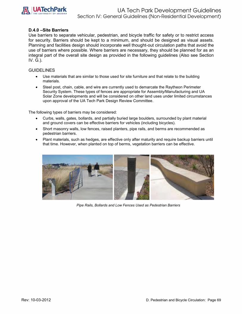
UA Tech Park Development Guidelines Section IV: General Guidelines (Non-Residential Development)
Rev: 10-03-2012 D. Pedestrian and Bicycle Circulation: Page 69
D.4.0 –Site Barriers Use barriers to separate vehicular, pedestrian, and bicycle traffic for safety or to restrict access for security. Barriers should be kept to a minimum, and should be designed as visual assets. Planning and facilities design should incorporate well thought-out circulation paths that avoid the use of barriers where possible. Where barriers are necessary, they should be planned for as an integral part of the overall site design as provided in the following guidelines (Also see Section IV. G.). GUIDELINES
Use materials that are similar to those used for site furniture and that relate to the building materials.
Steel post, chain, cable, and wire are currently used to demarcate the Raytheon Perimeter Security System. These types of fences are appropriate for Assembly/Manufacturing and UA Solar Zone developments and will be considered on other land uses under limited circumstances upon approval of the UA Tech Park Design Review Committee.
The following types of barriers may be considered:
Curbs, walls, gates, bollards, and partially buried large boulders, surrounded by plant material and ground covers can be effective barriers for vehicles (including bicycles).
Short masonry walls, low fences, raised planters, pipe rails, and berms are recommended as pedestrian barriers.
Plant materials, such as hedges, are effective only after maturity and require backup barriers until that time. However, when planted on top of berms, vegetation barriers can be effective.
Pipe Rails, Bollards and Low Fences Used as Pedestrian Barriers

UA Tech Park Development Guidelines Section IV: General Guidelines (Non-Residential Development)
Rev: 10-03-2012 E. Parking Lots and Parking Structures: Page 70
E. Parking Lots and Parking Structures This section provides standards for the siting and layout of parking lots and parking structures. Specific parking lot requirements and lot design criteria are provided in Section IV of this document. E.1.0 –Required Parking Ratios The UA Tech Park Master Plan requires that new development provides parking in numbers sufficient to meet, but not exceed, the projected parking needs of each user in conformance with minimum rates for on-site parking. Minimum rates for on-site parking for non-residential uses are provided in Section IV of this document. Minimum parking rates for residential, school and childcare development are provided in Section III of this document. E.2.0 –Parking – Surface Lots Locate and design parking lots so they will provide efficient vehicular circulation and safe pedestrian circulation within the site, while minimizing the visual impact of cars. Parking areas should be a visual asset to the UA Tech Park. Large expanses of pavement should be avoided. On-street parking is prohibited throughout the UA Tech Park, except on designated pedestrian routes. Each development parcel shall provide sufficient on-site parking at any one time to avoid overflow parking into adjacent lots or onto public streets. Specific design guidelines for surface parking lots are provided in Section VI. GUIDELINES
Provide adequate spaces for special parking requirements, such as handicapped, motorcycle and bicycle parking.
Design parking layout to maximize efficiency of traffic flow and to minimize vehicular and pedestrian conflicts.
Avoid large paved parking areas by breaking up these areas with building placement or landscaping elements.
Divide parking lots into smaller areas with planted buffers between them to minimize the perceived scale of the total field of parking stalls. (See Section IV.G.)
Provide adequate protection of landscaping and natural vegetation. Provide landscape treatments in parking areas that are consistent with the rest of the UA Tech
Park. Prohibit on-street parking throughout the UA Tech Park, except on designated pedestrian routes. Maximum recommended walking distances from the farthest parking space to a building should
be 200 feet for guest parking, and a preferred 500 feet for employee parking. Longer walking distances may be acceptable where the pedestrian way is well-designed and encourages walking.
Minimize the negative visual impact of parked cars with landscape design elements. Screen parking areas from view of public ways or designated view corridors with berms and other
landscaping (See Section IV.G). Connect parking lots with convenient service roads between lots. Design parking lots to discourage high speed driving, especially near building entrances. Avoid
aligning all travel lanes in parking lots in straight configurations that facilitate speeding. Design parking lots to avoid dead-end aisles. When feasible provide continuous access to
adjacent parking aisles, lots or roads. When dead-end situations are unavoidable, adequate space for unimpeded turn around must be provided.

UA Tech Park Development Guidelines Section IV: General Guidelines (Non-Residential Development)
Rev: 10-03-2012 E. Parking Lots and Parking Structures: Page 71
Parking standards for existing uses located in the Project Area currently exist. Standards for such uses are considered appropriate.
E.3.0 –Parking Standards Establish parking standards to ensure sufficient on-site parking for the different user needs of the Tech Park as provided in the following subsections. E.3.1 –Vehicle Parking Include compact, handicapped, motorcycle and electric vehicle charging spaces.
GUIDELINES
Compact stalls are limited to a maximum of 25% for commercial uses and 50% for light industrial, Research Park, and office uses.
E.3.2 –Carpool Parking If a carpool system is implemented conform to the following guidelines.
GUIDELINES
Designate a minimum of 10% of parking spaces for use by carpools. Locate carpool spaces in close proximity to employee entrances to encourage carpooling. Require that carpools provide transportation for a minimum of two employees.
E.3.3 –Motorcycle Parking Provide motorcycle parking areas at the rate of one area per 100 automobile parking spaces. Uses with 25-100 vehicle parking spaces provide one designated area for motorcycle parking. GUIDELINES
A motorcycle area shall consist of 56 usable square feet. Design and site motorcycle parking in such a way that is clearly distinguishable from automobile
parking. Identify parking stalls to encourage orderly positioning of parked vehicles. Provide security and visibility by locating motorcycle parking bays separately from automobiles to
minimize confusion.
E.3.4 –Helicopter Landing Site Provide a helicopter landing site in a central location near a primary access road. The heliport should comply with all Federal and State Regulations for heliport design, be located outside of the Davis-Monthan AFB Approach/Departure Zone, and conform to the following guidelines.

UA Tech Park Development Guidelines Section IV: General Guidelines (Non-Residential Development)
Rev: 10-03-2012 E. Parking Lots and Parking Structures: Page 72
GUIDELINES Locate heliport in close proximity to the desired origination and/or destination of the potential
users. Locate heliport adjacent to railroad, freeway or highway, to increase the potential for multi-
functional land usage. The landing pad perimeter must be a minimum of:
o Fifty (50’) feet from a property line or parcel line; o One thousand (1000’) feet from a property line or parcel line of a noise-sensitive land use; o Two thousand four hundred (2400’) feet from the perimeter of the landing pad of another
heliport or helistop; and o Three hundred (300’) feet from a public right-of-way.
Heliport accessory structures like maintenance and fueling facilities shall be a minimum of fifty (50’) feet from a property line or parcel line.
E.3.5 –Handicapped/ “Barrier Free” Parking Handicapped or “Barrier Free” parking spaces must be located in close proximity to accessible employee and visitor entrances and meet all ADA requirements. Provide handicapped parking spaces at the rates shown in Table 4, or based on actual needs.
Table 4: Handicapped or “Barrier Free” Parking Standards
Number of Automobile Spaces
Minimum Number of Handicapped Spaces Required
1 – 25 1
26 – 50 2
51 – 75 3
76 – 100 4
101 – 150 5
151 – 200 6
201 – 300 7
301 – 400 8
401 – 500 9
501 – 1,000 2% of total spaces
1,000+ 20 plus 1 for each 100 over 1,001

UA Tech Park Development Guidelines Section IV: General Guidelines (Non-Residential Development)
Rev: 10-03-2012 E. Parking Lots and Parking Structures: Page 73
E.3.6 –Electric Vehicle Charging Parking Provide reserved parking spaces for the charging of electric vehicles as needed in conformance with the following guidelines. These spaces will count toward the total number of required spaces. GUIDELINES
Provide reserved parking spaces for the charging of electric vehicles in close proximity to employee or visitor entrances, and at a minimum distance to a power source (See also C.9) Energy Conservation/Air Control).
A charger typically utilizes one standard size parking space. Space must be available for signage and wheel stops.
Preferred locations for such charging stations and/or parking spaces include landscape islands, utility transformer locations (if near building entrances), and parking structure walls near walkways.
E.3.7 –Parking Dimensions for Surface Parking Lots Parking dimensions for surface parking lots must conform to minimum standard for surface parking lots provided in Table 5 to ensure appropriate spacing and maneuvering.
Table 5: Minimum Standards for Surface Parking Lots
Parking Type Minimum Standard
Standard 9 feet wide by 20 feet long
Handicapped Space
12 feet wide by 20 feet long. Two adjacent handicapped spaces may share the loading area
Motorcycle Area
6 feet wide by 9 feet long or usable area of 56 square feet
Bicycle Rack
3 feet by 8 feet
Parking lots constitute a major portion of impervious surface area in the Tech Park. To minimize surface run-off from storms, the following guidelines apply. GUIDELINES
Encourage the development of sets of smaller lots as a way of accommodating infiltration systems.
Drainage from parking lots should be dispersed in a manner that promotes infiltration and reduces erosion.
Provide a pavement slope between 1.5% and 2% to minimize depressions in paving. Refer to B: Stormwater Management/Drainage for additional guidelines.

UA Tech Park Development Guidelines Section IV: General Guidelines (Non-Residential Development)
Rev: 10-03-2012 E. Parking Lots and Parking Structures: Page 74
E.4.0 –Parking Structures and Parking under Buildings The appearance of parking structures, either free-standing or attached, should relate to the “parent” building and should positively contribute to the character of the site. Structures that are integrated into the main building are preferred. Specific guidelines for Parking Structures are provided in Section VI.
GUIDELINES
The general architectural guidelines should apply to all parking structures, specifically with regard to mass, scale, and materials.
Screen the headlights of cars from view at the ground level. Conceal the views of cars, where parking levels are integrated into primary buildings, especially if
the first floor along the façade contains the primary pedestrian entrance to the building. Soften the view of the top floor of the parking deck from view of upper floors of adjacent offices
with architectural screens and landscaping. Design a facade that is visually pleasant to the pedestrian, where the ground level of the parking
structure faces onto a major public way. Examples include decorative screens, murals, public art, and plant materials.
E.5.0 –Development of Future Lots and Structures Many projects are likely to be built out in phases, and parking design should work well in each of the phases. Provisions should be made on the site for increased parking demand through the expansion or changes of use of each building.
GUIDELINES
Planning for future parking is required at the outset, where additional building space may be developed in later phases.
Compatibility of future parking lots (and especially structures) will be an issue for review at later development stages.
Alternatives to conventional barriers should be considered, including: changes in levels between walkways and surrounding areas; benches, seating walls, bike racks, etc. along the edge of a designated route; and movable barriers such as gates, barricades, etc. that fold down or recess into the pavements only under special circumstances.
E.6.0 –Safety and Visibility – Defensible Space Safety and visibility, especially at night, is of primary concern to the UA Tech Park. The latest principles of homeland security-crime preventive design and defensible space are encouraged in the planning and design of outdoor space, particularly for major pedestrian paths, parking areas, and usable open spaces. This means design which discourages criminal activity and encourages visual surveillance by Tech Park users as Tech Park security will be emphasized. Encourage the utilization of homeland security-crime preventive design and defensible space in the planning and design of outdoor space, particularly for major pedestrian paths, parking areas, and usable open spaces in accordance to the following guidelines.
GUIDELINES
Utilize the concepts of defensible space design, e.g., Crime Prevention Through Environmental Design (CPTED).
Incorporate a building-wide electronic security system when deemed appropriate.

UA Tech Park Development Guidelines Section IV: General Guidelines (Non-Residential Development)
Rev: 10-03-2012 E. Parking Lots and Parking Structures: Page 75
Provide ample lighting directed towards all parts of the area surrounding the building or parking facility.
Bicycle parking areas shall be well lit and free of high screens or shrubs which could conceal criminal activity.
Provide comfortable lighting height for pedestrians that is directed down to light walkways, rather than upward.
Identify vulnerable areas of buildings having after hour user access. Secure these areas to be highly visible and safe for users.
Encourage the use of "blue-light" emergency phones.
E.7.0 –Park-and-Ride Facilities Park-and-ride lots provide a collection point for travelers to transfer between the automobile mode and transit, or between the single occupant vehicle (SOV) and high occupancy vehicle modes. Other modes potentially supported by the park-and-ride facility at the UA Tech Park include pedestrian, bicycle, intercity bus transit, UA Tech Park shuttle, airport service, and intercity and commuter rail, if available. The park-and-ride facility at the UA Tech Park must be constructed to provide a convenient area for commuters to park and carpool or take public transportation in conformance with the following general guidelines. GUIDELINES
Locate park-and-ride facilities in close proximity to major highway serving commuters. Locate park-and-ride facilities in close proximity to UA Tech Park signature entries, with direct
access to Kolb Activity Node and/or Rita Road Activity Node and in close proximity to commercial and office uses, restaurants, and hotels.
Provide ambient lighting and security for night users. Ensure quality design elements such as effective lot circulation, easy access and egress, ample
parking, bicycle accommodations, attractive landscaping, lighting, bus shelters, phones, and security are incorporated in the design.
Ensure proper maintenance of quality design elements.
E.7.1 –Design Considerations The design of the park-and-ride facility should consider anticipated parking demand, parking facility design standards, circulation patterns, and drainage facilities. Key design guidelines for park-and-ride lots are provided in this subsection. E.7.1.1 –Site Location The location of park-and-ride facilities should consider the following design guidelines.
GUIDELINES
Consider site terrain, drainage, and available space compared to the required lot size. Minimize impacts to Julian Wash or any other surrounding washes. Ensure compatibility with surrounding land uses. Locate park-and-ride facilities in close proximity to high-intensity land uses with high parking
demand such as hotel, retail, office, restaurants and Research Park.

UA Tech Park Development Guidelines Section IV: General Guidelines (Non-Residential Development)
Rev: 10-03-2012 E. Parking Lots and Parking Structures: Page 76
E.7.1.2 –Multi-modal Access: Design park-and-ride facilities to provide access and connectivity into existing transit, bicycle, pedestrian, and trail systems.
GUIDELINES
Provide safe and convenient access to existing and proposed transit, pedestrian, bicycle, and trail systems.
Provide safe and convenience access to hotel, commercial, restaurants, and other high intensity uses located in close proximity to the park-and-ride facility.
E.7.1.3 –Safe and Convenient Circulation: Design park-and-ride facilities to provide safe pedestrian and bicycle circulation.
GUIDELINES
Incorporate separate vehicular, transit, pedestrian, and bicycle circulation and access in parking layout.
Ensure that bus, shuttle, and vehicular drop-off areas are separate from each other and clearly marked with specialty paving and signs.
Provide dedicated bus ways and short-term parking and drop-off/pickup space near bus stops or bus loading areas.
Pedestrian connections, crosswalks, and paths must be provided throughout the lot to the transit area and to nearby buildings.
Align parking spaces within parking areas 90 degrees to the direction of pedestrian travel to ensure clear routes and maximize visibility.
Consider providing a separate walkway between parking bays that aligns with bus and/or shuttle stop and loading area.
Provide a bicycle area with covered racks or lockers, if bicyclists are expected to commute to the park-and-ride facility.
E.7.1.4 –Site Access/Egress: Design park-and-ride facilities to provide safe and convenient site access/egress in accordance with the following guidelines.
GUIDELINES
Provide separate driveway exists and entrances if feasible and possible. Provide at least one exit and one entrance for every 500 parking spaces provided. Allow a minimum distance of 500 feet from between access points.
E.7.1.5 –Parking: The number of parking spaces to be provided in a new or expanded park-and-ride facility should be determined using UA Tech Park information and in coordination with Pima Association of Governments (PAG). Design park-and-ride facilities to provide sufficient parking spaces in accordance with the following guidelines.
GUIDELINES

UA Tech Park Development Guidelines Section IV: General Guidelines (Non-Residential Development)
Rev: 10-03-2012 E. Parking Lots and Parking Structures: Page 77
Coordinate number of parking space with PAG. Base number of required parking spaces in accordance to projected demand. Determine the size of drop-off/pickup area and the number of associated short-term spaces in
accordance to projected demand. Provide bicycle parking at a rate of 1 space for every 10 to 20 vehicle spaces. Provide right-angle parking with sufficient aisle width for two-way travel. Where space is limited, angle parking with one-way travel is acceptable. Provide accessible parking at the rates provided in Table 1 (E.3.5) Observe the Minimum Standards for Surface Parking dimensions provided in Table 2 (E.3.7)
E.7.1.6 –Sidewalks and Walkways: Sidewalks and walkways within park-and-ride facilities must conform with the following guidelines. GUIDELINES
Require a minimum width of 7 feet sidewalks within park-and-ride facilities. Provide a minimum width of 12 feet sidewalks within park-and-ride loading areas. Build wheelchair ramps for access onto sidewalks and loading areas.
E.7.1.7 –Grading and Drainage: The following guidelines for grading and drainage apply. GUIDELINES
If buses will use the park-and-ride facility, ensure that grade does not exceed 7 percent. A maximum grade of 5 percent is preferred. Grades may be steeper in facilities where only automobiles will use the park-and-ride lot.
Ensure that drainage design does not pond on pedestrian routes, bicycle routes, drop-off/pickup, or loading areas.
E.7.1.8 –Signage, Lighting, and Security: The following guidelines for signage, lighting, and security apply. GUIDELINES
Require that all directional signs, pedestrian crossing signs, bicycle route markings and signing, and traffic control signs are built in accordance with all applicable guidelines for signage provided in Chapter H of this document.
Require that all lighting features provided in park-and-ride facilities are built in accordance with all applicable guidelines for lighting provided in Chapter J and subsection J.4.0 of this document.
At the design stage, consider the incorporation of adequate security measures, which may include: o Safe by design principles; o Random security patrols; o Provision of emergency call boxes; and o Provision of safety information brochures to patrons.

UA Tech Park Development Guidelines Section IV: General Guidelines (Non-Residential Development)
Rev: 10-03-2012 E. Parking Lots and Parking Structures: Page 78
E.7.1.9 –Solid Waste and Recycling Pickup: The following guidelines for solid waste and recycling pickup apply. GUIDELINES
At the design stage, incorporate information of plans for collection of trash and recycling for all proposed park-and-ride facilities.
E.7.1.10 –Landscaping: The following guidelines for landscaping apply. GUIDELINES
Require that all landscape areas within park-and-ride facilities comply with all applicable standards provided in Chapter G and subsection G.5.0 of this document.
E.8.0 –Solar Powered Covered Parking: Surface parking areas as well as Park-and-Ride facilities provide an opportunity to include convenient shaded parking with incorporated solar panels for clean energy generation, converting parking lots into solar power plants. Surface parking and Park-and-Ride facilities at the UA Tech Park present an opportunity for clean energy generation. GUIDELINES
Incorporate covered parking with solar panels on surface parking areas and Park-and-Ride facilities located at the UA Tech Park.
Illustration 28: Surface Parking and Park-and-Ride Facilities with Solar Powered Covered Parking

UA Tech Park Development Guidelines Section IV: General Guidelines (Non-Residential Development)
Rev: 10-03-2012 F. Architectural Design: Page 79
F. Architectural Design Architectural guidelines are established to promote the creation of a unique, recognizable and consistent architectural character for the UA Tech Park. These guidelines are intended to promote flexibility. They allow individuality of building character, while maintaining a sense of overall harmony throughout the project and its adjacent developments. The guidelines also define how buildings complement each other through coordination of size, materials, colors, building mass, height, and spatial articulation. Due to the project’s proximity to the Tucson International Airport and Davis-Monthan Air Force Base, Interstate 10 and the Union Pacific Rail Road tracks, special attention must be given to building height restriction and building sound attenuation. Design of buildings must meet all applicable Federal Aviation Administration (FAA) regulations. Architectural design must be reviewed and approved by the UA Office of University Research Parks Design Review Committee. F.1.0 –Architectural Character Buildings should visually relate to other buildings in the Research Park. The architectural style for new development shall complement that of existing development. GUIDELINES
Utilize architectural styles that are modern, progressive and reflect current state of the art construction technology in design and concept.
Rely on the dynamic contrast and balance between individual building expression and the ability of new structures to interact visually with neighboring buildings to create a strong sense of unity and community.
Provide easily identifiable building form, using building numbers, maps, signs, and kiosks where feasible and appropriate.
Minimize the large-scale visual impacts of buildings. Make provisions for outdoor “people places” such as plazas, courtyards and atriums. Use cantilever-style catwalks to physically and symbolically link adjacent buildings and to create a
modern architectural effect. Appropriate areas within the UA Tech Park for such a technique are Research Park and Business Development/Hospitality areas.
Incorporate energy-efficient building design and materials into all new buildings in the UA Tech Park.
Express the unique, special character, function and nature of the building while respecting and harmonizing with surrounding architecture.
The building character within the UA Tech Park Center should incorporate design characteristics that define a pedestrian–oriented, high-density compact urban environment with parking integrated into buildings.
New buildings built within the existing Project Area of the UA Tech Park should consider the character and quality of the existing buildings but should not replicate them.
Encourage “four-side” architectural treatment.
F.2.0 –Building Site Planning Design building placement, orientation, and massing to create visual interest from off-site as well as on-site. Proper building site planning also ensures efficient and optimum use of a development parcel.

UA Tech Park Development Guidelines Section IV: General Guidelines (Non-Residential Development)
Rev: 10-03-2012 F. Architectural Design: Page 80
Illustration 29: Incorporate a Variety of Building Heights to Create
Architectural Character and an Interesting Skyline.
GUIDELINES
Vary building setbacks along the street frontage. Create aesthetically interesting and functional exterior spaces such as plazas, courtyards and
pedestrian walkways through coordinated placement and orientation of buildings. Orient buildings to maximize view potential to the open spaces and to mountain views. Internalize and group together service and loading areas, creating a shared service zone, or
design service areas underground and away from view. Place and orient buildings to maximize visibility from freeways, and local arterials. Site buildings to minimize the impact of large paved parking areas.
F.3.0 –Building Heights and Skylines Design structures and building complexes with a variety of heights to create visual interest and minimize monotony along the street frontage, provided that the maximum building height is not exceeded. GUIDELINES
Building heights must respect all related Federal Aviation Administration safety regulations. Building heights are restricted based on their type of use as well as the maximum height limits
provided in Section IV of this document. Large-scale buildings may vary their heights at the building entrance and lobby area, provided
that the maximum building height is not exceeded.
F.4.0 –Building Massing and Scale (Façade and Details) Design building façades and details to convey a hierarchy of order, and to create visual interest through the interplay of light, shadow, color and texture.
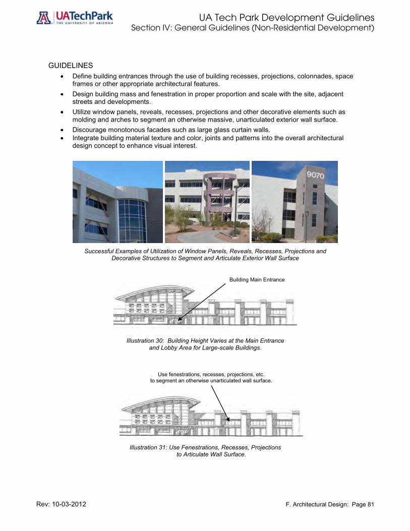
UA Tech Park Development Guidelines Section IV: General Guidelines (Non-Residential Development)
Rev: 10-03-2012 F. Architectural Design: Page 81
GUIDELINES Define building entrances through the use of building recesses, projections, colonnades, space
frames or other appropriate architectural features. Design building mass and fenestration in proper proportion and scale with the site, adjacent
streets and developments. Utilize window panels, reveals, recesses, projections and other decorative elements such as
molding and arches to segment an otherwise massive, unarticulated exterior wall surface. Discourage monotonous facades such as large glass curtain walls. Integrate building material texture and color, joints and patterns into the overall architectural
design concept to enhance visual interest.
Successful Examples of Utilization of Window Panels, Reveals, Recesses, Projections and
Decorative Structures to Segment and Articulate Exterior Wall Surface
Building Main Entrance
Illustration 30: Building Height Varies at the Main Entrance and Lobby Area for Large-scale Buildings.
Use fenestrations, recesses, projections, etc. to segment an otherwise unarticulated wall surface.
Illustration 31: Use Fenestrations, Recesses, Projections
to Articulate Wall Surface.
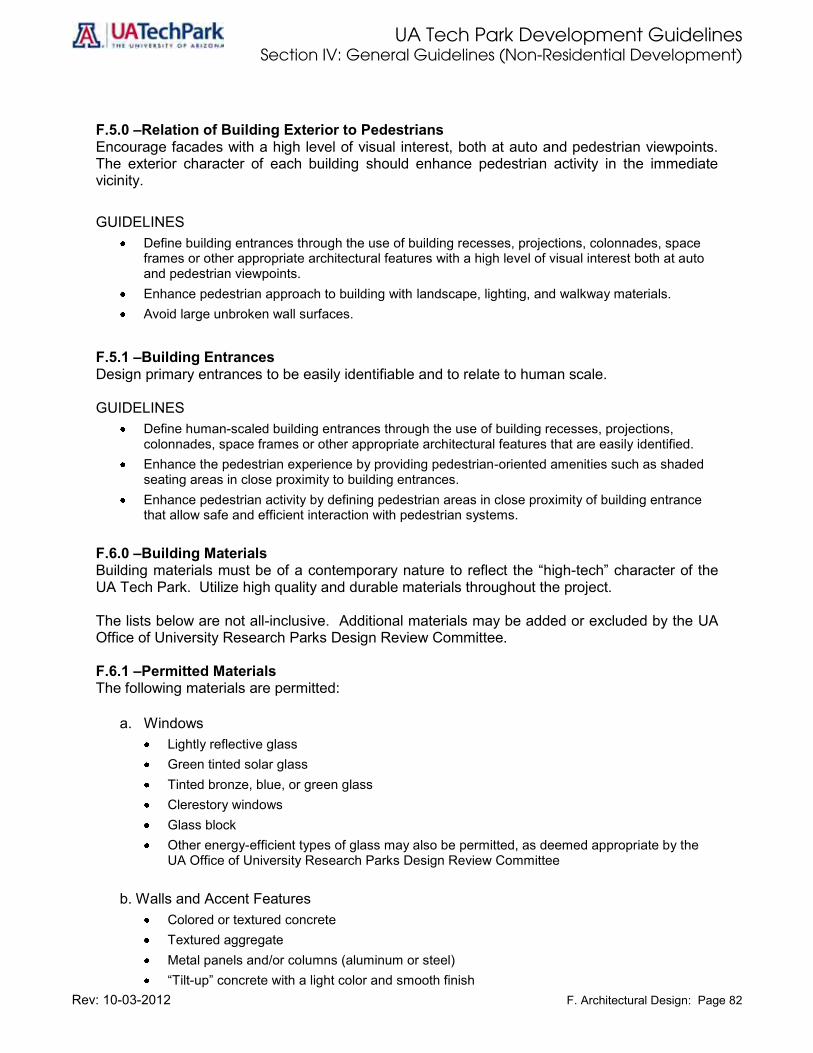
UA Tech Park Development Guidelines Section IV: General Guidelines (Non-Residential Development)
Rev: 10-03-2012 F. Architectural Design: Page 82
F.5.0 –Relation of Building Exterior to Pedestrians Encourage facades with a high level of visual interest, both at auto and pedestrian viewpoints. The exterior character of each building should enhance pedestrian activity in the immediate vicinity.
GUIDELINES Define building entrances through the use of building recesses, projections, colonnades, space
frames or other appropriate architectural features with a high level of visual interest both at auto and pedestrian viewpoints.
Enhance pedestrian approach to building with landscape, lighting, and walkway materials. Avoid large unbroken wall surfaces.
F.5.1 –Building Entrances Design primary entrances to be easily identifiable and to relate to human scale.
GUIDELINES
Define human-scaled building entrances through the use of building recesses, projections, colonnades, space frames or other appropriate architectural features that are easily identified.
Enhance the pedestrian experience by providing pedestrian-oriented amenities such as shaded seating areas in close proximity to building entrances.
Enhance pedestrian activity by defining pedestrian areas in close proximity of building entrance that allow safe and efficient interaction with pedestrian systems.
F.6.0 –Building Materials Building materials must be of a contemporary nature to reflect the “high-tech” character of the UA Tech Park. Utilize high quality and durable materials throughout the project.
The lists below are not all-inclusive. Additional materials may be added or excluded by the UA Office of University Research Parks Design Review Committee. F.6.1 –Permitted Materials The following materials are permitted:
a. Windows
Lightly reflective glass Green tinted solar glass Tinted bronze, blue, or green glass Clerestory windows Glass block Other energy-efficient types of glass may also be permitted, as deemed appropriate by the
UA Office of University Research Parks Design Review Committee
b. Walls and Accent Features Colored or textured concrete Textured aggregate Metal panels and/or columns (aluminum or steel) “Tilt-up” concrete with a light color and smooth finish

UA Tech Park Development Guidelines Section IV: General Guidelines (Non-Residential Development)
Rev: 10-03-2012 F. Architectural Design: Page 83
Light color brick Rock Silver-gray colored tile
c. Roofs
Light colored metal Tile that reflects the high tech architectural style of the Tech Park Slate roofing Foam buildup roofs
F.6.2 –Prohibited Materials The following materials are not permitted:
a. Windows
Highly-reflective glass
b. Walls Wood Concrete block without texture or color
c. Roofs
Wood Shingles or shakes Asphalt or tar shingles Spanish or Mexican Tile
F.7.0 –Building Colors Colors must be complementary to each other and to adjacent buildings in general. Use accent colors only to add interest at focal areas and entries. Subtle changes in wall color to avoid a massive façade are allowed provided such practice is used in a limited manner. The color theme of each building must be reviewed and approved by the Tech Park Design Review Committee.
GUIDELINES Colors must be harmonious and complementary to each other. Light colors such as light earth
tones with accent colors may be used as a general theme throughout the project. Highly contrasting colors and bold graphic patterns on building facades are not permitted. Buildings must have one overall color theme. Accent colors may be applied at main entrances or
other special focal areas. Accent colors must not be painted on wall surfaces and used as wide bands. Roof colors must also be light and complementary to the overall color theme of the buildings.

UA Tech Park Development Guidelines Section IV: General Guidelines (Non-Residential Development)
Rev: 10-03-2012 F. Architectural Design: Page 84
F.8.0 –Roofs, Penthouses and Mechanical Equipment Screens Roof design must be contemporary and visually integrated into the overall building architecture. Roof tops should contribute to the visual continuity of the UA Tech Park, and should be considered as a design element that will be seen from various viewpoints at ground level, from other buildings, and from adjacent perimeter roadways. Any mechanical equipment and penthouses must be properly screened and such screens must be integrated with the building façade.
GUIDELINES In general, roofs are to be flat or semi-curved to reflect the contemporary character of the UA
Tech Park. Sloped and curved forms may be used at entries or other focal areas as long as they are not the
dominant roof theme. Mansard and hip roof forms are not permitted. Screens for roof-mounted mechanical equipment and penthouses must be constructed of
materials compatible with the building facades. All roof screens shall be solid and continuous. Continuous grills or louvers must cover mechanical equipment. Communication devices such as satellite dishes and antennas should not be roof-mounted unless
technically necessary, in which case, the top of the equipment must be below the top of the parapet or equipment screen to be invisible from the ground. These types of devices may be integrated into the structure.
Illustration 32: Roof Top Screening for Mechanical and Communication Equipment.
F.8.1 –Mechanical Equipment All mounted mechanical equipment must be screened from public view. Screening of such equipment must be architecturally integrated with the main structure in terms of materials, shape, color and size.
GUIDELINES Locate exhaust vents away from major building façade facing the public street. Paint ducts, pipes, gutters, downspouts, and similar equipment to match the surface of the
building.

UA Tech Park Development Guidelines Section IV: General Guidelines (Non-Residential Development)
Rev: 10-03-2012 F. Architectural Design: Page 85
F.8.2 –Roof-Mounted Solar Collectors Roof-mounted solar collectors are solar panels mounted on the roof of buildings. The following guidelines apply. GUIDELINES
Roof-mounted solar panels and accessory equipment must be integrated into the design of the building or be placed on roofs in locations that are concealed from public view.
Roof-mounted solar devices must be installed in a manner that minimizes glare into adjacent properties.
Roof-mounted solar collectors should match the roof pitch and be placed in close proximity to the surface of the roof below them.
The panels must be installed at the same angle as the roof and the top of the solar panel shall not be more than eight (8) inches higher than the surface of the roof below it.
Accessory equipment located on the ground should be screened from off-site view through careful placement and/or the use of landscaping or fencing.
All installed equipment shall allow for roof maintenance.
Projects of this type located within the Project Area must comply with the Project Operation Agreement (POA).
F.8.3 – Ground Mounted Solar Collectors Ground-mounted solar collectors are solar panels mounted on the ground adjacent to the buildings and/or facilities they are serving or being fed into the electric grid. The following guidelines apply. GUIDELINES
Ground-mounted solar panels and accessory equipment must be secured through careful placement and/or the use of landscape or fencing, providing that such landscape or fencing does not impede solar collection.
Ground-mounted solar devices must be installed in a manner that minimizes glare into adjacent properties.
F.9.0 – Loading, Service and Delivery Areas All service areas must be accommodated on-site, not visible from the public right-of-way. Loading, service and delivery areas must be located on the side or rear of a building or underground, not visible from the public right-of-way. Such spatial arrangement can maximize site efficiency and minimize adverse visual impact of the service areas.
GUIDELINES Loading docks and service areas must not be visible from the street, freeway, open spaces, or
public right-of-way. Where loading docks and service areas front a public street, freeway or open space, screening must be provided so that these areas are not visible from the adjacent uses through a combination of screen walls, landscaping and/or extensions of the building wall.
Screening walls for the service areas must be compatible with the main building structure in terms of color, form and materials.

UA Tech Park Development Guidelines Section IV: General Guidelines (Non-Residential Development)
Rev: 10-03-2012 F. Architectural Design: Page 86
Service areas must be designed to provide for backing and maneuvering on-site and not from a public street.
Truck docks and loading doors must be well organized and integrated into the building design.
F.10.0 – Energy Conservation Buildings must meet and/or exceed energy efficiency and conservation guidelines for commercial construction. Use of passive and active devices and techniques to improve building energy performance must be integrated into all new buildings and any retrofitting of existing buildings in the UA Tech Park.
GUIDELINES Design and orient buildings to take advantage of solar access. Integrate energy-efficiency building materials, sensible building orientation (i.e. passive solar),
shading devices and techniques such as recessed windows, overhangs, and interior shading devices such as blinds into building design.
Encourage the use of energy efficiency and conservation systems designed to shift utility demand such as gas and electricity at off-peak hours.
Use reflective or solar glass to limit transfer of heat while maximizing available sunlight for interior illumination, where feasible and appropriate.
F.11.0 – Open Spaces Incorporated in New Buildings Plazas, courtyards, and terraces that are incorporated as public amenities in or between new buildings should be designed to be easily accessible and to be reasonably comfortable for a substantial part of the year.
F.12.0 – Outdoor Public Art Public art should be encouraged throughout the UA Tech Park to enhance the visual quality of the Tech Park. Artwork designed by students or faculty of the University of Arizona should be used whenever possible, provided it is approved by the UA Tech Park Design Review Committee. All buildings must provide public art. GUIDELINES
Dedicate one percent (1%) of construction value for the provision of outdoor public art. Locate artwork so that it is reasonably visible or accessible to the public from a major road, open
space area or building entrance. Consider durability of the art material. Ongoing maintenance is the responsibility of the building
owner.
F.13.0 –UA Office of University Research Parks Design Review Committee The UA Office of University Research Parks Design Review Committee reviews all development plans for compliance with the UA Tech Park Master Plan and these Development Guidelines. The UA Office of University Research Parks Design Review Committee shall review and approve all new development occurring at the UA Tech Park. The Project Area of the UA Tech Park is also covered by the Project Operation Agreement. The Committee shall be composed of at least five (5) active members, appointed by the President of the University of Arizona or his/her designee, including: the UA Tech Park Director, a representative from the University’s Office of Campus and Facilities Planning, a representative from the University’s College of Architecture, Planning and Landscape Architecture, and two

UA Tech Park Development Guidelines Section IV: General Guidelines (Non-Residential Development)
Rev: 10-03-2012 F. Architectural Design: Page 87
representatives from Ward 4 of the City of Tucson. One Committee member must be certified by Leadership in Energy & Environmental Design (LEED) on Green Building Rating System for New Construction and Major Renovations. The UA Office of University Research Parks Design Review Committee must include an architect, a landscape architect, and an engineer certified in their respective fields. F.14.0 – Noise Insulation All buildings within the 0-30,000 feet Approach/Departure Corridor, except assembly and manufacturing and Tech Park operation facilities, must be provided with appropriate noise insulation or otherwise designed to reduce the interior noise level to 45 DNL or less.

UA Tech Park Development Guidelines Section IV: General Guidelines (Non-Residential Development)
Rev: 10-03-2012 G. Landscape: Page 88
G. Landscape The landscape theme for the UA Tech Park must render a distinctive identity to the project, while maintaining consistency with the established framework of adjacent developments. The image is a clean, contemporary “high-tech” character that is complementary to the architectural style and the uses. In general, planting design must be organic, innovative, colorful, and in some instances repetitive. The plant palette must be simple, comprised of native vegetation and other suitable vegetation requiring very little water, maintenance and upkeep, as provided in the plant list included in Appendix A of this document. Plants selected should also be non-allergenic, have a non-invasive root system, and be pest and disease resistant. All landscaped areas shall be of high quality and well maintained year round. The landscape development character for these parcels can be divided into two primary landscape design components: Streetscape and On-Site Landscaping. Streetscape applies to treatment of parkways adjacent to roadways (both within the UA Tech Park and along its outer perimeter), and landscape treatment along freeway edges and intersections. On-site landscaping encompasses entry zones; parking areas; pedestrian plazas and courtyards; building perimeters; loading/service areas; and side and rear setback areas. Guidelines for each of these design components are discussed in the following sections. G.1.0 – Landscape Design Concept The landscape design concept of the UA Tech Park is best described as a reflection and an enhancement of the existing environment. The design concept does not seek to change the landscape from its current form. GUIDELINES
Require that landscape design respects the natural occurring riparian corridors utilizing them as such and as recreational amenities.
Ensure that the riparian corridors are reflected throughout the Tech Park and utilized as the character or theme for the primary and secondary roadways.
Require that additional open spaces and buffers take on the character of the existing natural environment, which currently exists at the UA Tech Park.
G.2.0 – Landscape for Roadway Corridors (Streetscapes) Streetscape treatment in the UA Tech Park must be clean, simple, modern and bold in character. A hierarchy of street scene can be established through the articulation of setback width and landscape design. Focal points must be placed at the major intersection areas while landscaping along the arterials must have minimal accent planting in order to promote a strong continuous edge. GUIDELINES
Design roadway corridors to serve as visually cohesive open spaces throughout the UA Tech Park.
Use similar landscape elements at all entrances and intersections in accordance to hierarchy of entrance.
Ensure that plant material massing, spacing and height provide visual clues to motorists about the hierarchy of roadways.
Roadway planning and grading will work together to create a variety of experiences along the road and to call attention to the open space corridors.

UA Tech Park Development Guidelines Section IV: General Guidelines (Non-Residential Development)
Rev: 10-03-2012 G. Landscape: Page 89
Adjoining parcels for future phase development will have the required streetscape fully implemented when the first phase of development occurs. This will include the planting of street trees and the hedges for parking lots screening.
Prior to the preparation of a final landscape plan, a designated landscape architect must review impacts on underground utilities.
All trees are to be a minimum 24 inches box and shrubs/hedges are to be a minimum 1 gallon size when installed.
Landscape berms must average no more than 4 feet in height and must be at least 2 feet in height. Turf areas on berms facing the street front must have slopes no steeper than 3:1, while slopes at the back of the berms must be no steeper than 2:1. Ground cover must be used on slopes steeper than 3:1.
Illustration 33: Landscaped Berm.
The use of a hedge screen is only required where parking lots and access drives front directly
onto the streetscape zone. In the absence of a parking area and access drive between a building and the streetscape area, an informal shrub mass can be used as an alternative to a formal hedge at the building perimeter or ground cover.
Shared landscaping can be used as a unifying element creating visual linkages between buildings.
Streetscape zones shall be well maintained year round. Deceased or disease-ridden plants shall be replaced promptly with materials comparable in size to existing plants.

UA Tech Park Development Guidelines Section IV: General Guidelines (Non-Residential Development)
Rev: 10-03-2012 G. Landscape: Page 90
Illustration 34: Building Perimeter Planting.
G.3.0 –On-Site Landscaping On-site landscaping is the responsibility of the UA Tech Park, and must be reviewed and approved by the UA Research Parks Design Review Committee as part of the development site plan approval process. The objectives for on-site landscaping guidelines are to establish compatibility of the general landscape image among development areas, and to ensure proper coordination with adjacent streetscapes and common property line landscaping. The guidelines also set provisions for individual identity and flexibility within each parcel. GUIDELINES
On-site landscaping within the Tech Park must be of simple and geometric composition, in scale with the building mass, parking areas and adjacent street width.
Use a limited plant palette in conformance with plant list provided in Appendix A. Establish a theme plant palette; plants from this palette should be used repeatedly throughout the
Tech Park to establish a sense of landscape consistency and order, and to bring attention to areas of significance (Appendix A provides plant palette for the different uses within the Tech Park).
Plant large sweeps of single species along street frontages and vehicular entries. Include massing of similar plant materials in side and rear yards, and parking lot areas. Encourage more detailed treatments, such as accent trees and shrubs, at formal building entries,
pedestrian plazas and courtyards. Require that on-site finished grades must meet existing street grades. Coordination with adjacent properties is required when landscaping is located at the following: (1)
common driveways shared with adjoining parcels; and (2) driveways along common property lines.
G.3.1 –Landscaping at Primary and Secondary Roadway Intersection Landscape character at primary and secondary roadway intersections should be consistent with the character of roadways and entries provided in the Circulation and Access section of this document.

UA Tech Park Development Guidelines Section IV: General Guidelines (Non-Residential Development)
Rev: 10-03-2012 G. Landscape: Page 91
GUIDELINES Use palms and trees listed in the plant list provided in Appendix A as the primary theme for the
streetscape. Use these palms and trees to frame the street section and create a sense of place within the
Tech Park. Accentuate the streetscape with massings of flowering bushes and shrubs listed in Appendix A to
add a unique textural quality to the landscape.
G.3.2 –Landscaping at Pedestrian Streets Provide amenities that enhance the pedestrian experience within common areas throughout the Tech Park. GUIDELINES
Use plant materials listed in the plant list provided in Appendix A as the primary theme for pedestrian pathways.
Provide seating opportunities under shaded areas along pedestrian pathways, trails and sidewalks in the form of fixed benches, informal berms, and seatwalls.
Provide picnic tables, trash receptacles and bicycle racks in pedestrian gathering areas within the street corridor at pocket parks, and along linear parks.
Accentuate pedestrian pathways with plant materials listed in Appendix A.
G.3.3 –Landscape Guidelines for Individual Building Parcels Coordinated landscape design of individual building parcels is essential for creating the character of the UA Tech Park. A cohesive landscape design will serve to unify the various buildings and strengthen the feeling of a unique research park. The landscape treatment for each parcel must complement the roadway landscapes, create a distinctive setting for the building and help reinforce the open space system. GUIDELINES
Require a landscape plan prepared by a registered landscape architect and approved by the UA Office of University Research Parks Design Review Committee as a condition for plan approval.
Use plant materials listed in the plant list provided in Appendix A for each type of land use. Provide landscape amenities within setbacks as required in the Site Planning section of this
document utilizing plant materials provided in Appendix A. Landscape amenity areas within building setback areas should provide contouring of the ground
plane to create a natural progression. Create opportunities for water harvesting within landscape amenities.
G.4.0 – Entry Zone An entry zone is the transition area between the public street access point and the private building entrance. This zone includes the entry driveway, access to parking areas, visitor parking and drop-off area, and the building entry area. As the entry zone sets the image and identity of a development parcel, a special landscape treatment shall be applied in conformance with the following guidelines.
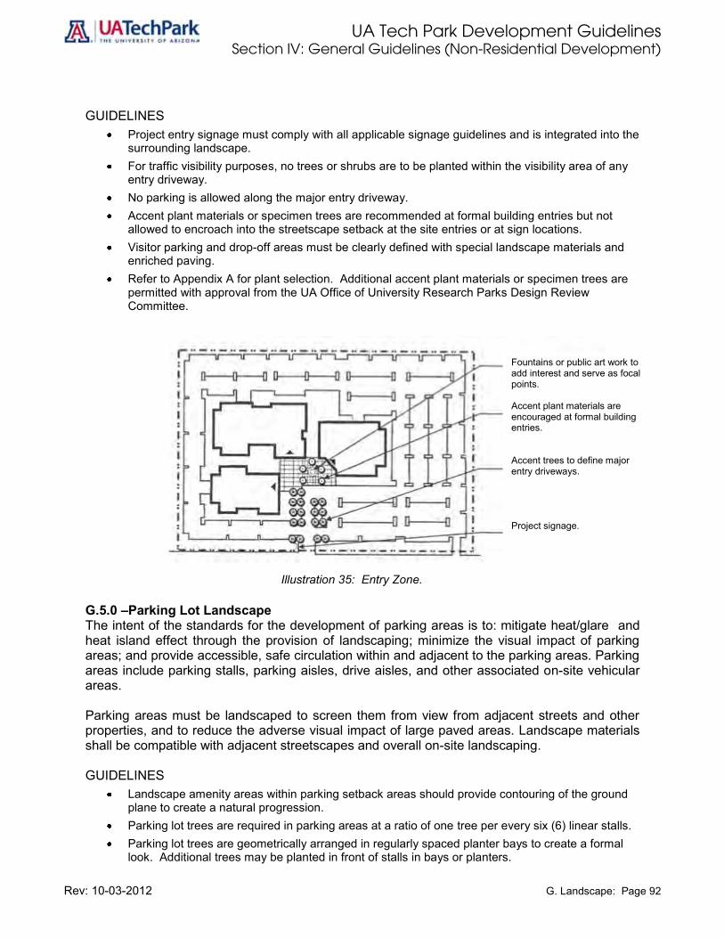
UA Tech Park Development Guidelines Section IV: General Guidelines (Non-Residential Development)
Rev: 10-03-2012 G. Landscape: Page 92
GUIDELINES Project entry signage must comply with all applicable signage guidelines and is integrated into the
surrounding landscape. For traffic visibility purposes, no trees or shrubs are to be planted within the visibility area of any
entry driveway. No parking is allowed along the major entry driveway. Accent plant materials or specimen trees are recommended at formal building entries but not
allowed to encroach into the streetscape setback at the site entries or at sign locations. Visitor parking and drop-off areas must be clearly defined with special landscape materials and
enriched paving. Refer to Appendix A for plant selection. Additional accent plant materials or specimen trees are
permitted with approval from the UA Office of University Research Parks Design Review Committee.
Illustration 35: Entry Zone.
G.5.0 –Parking Lot Landscape The intent of the standards for the development of parking areas is to: mitigate heat/glare and heat island effect through the provision of landscaping; minimize the visual impact of parking areas; and provide accessible, safe circulation within and adjacent to the parking areas. Parking areas include parking stalls, parking aisles, drive aisles, and other associated on-site vehicular areas. Parking areas must be landscaped to screen them from view from adjacent streets and other properties, and to reduce the adverse visual impact of large paved areas. Landscape materials shall be compatible with adjacent streetscapes and overall on-site landscaping. GUIDELINES
Landscape amenity areas within parking setback areas should provide contouring of the ground plane to create a natural progression.
Parking lot trees are required in parking areas at a ratio of one tree per every six (6) linear stalls. Parking lot trees are geometrically arranged in regularly spaced planter bays to create a formal
look. Additional trees may be planted in front of stalls in bays or planters.
Fountains or public art work to add interest and serve as focal points. Accent plant materials are encouraged at formal building entries. Accent trees to define major entry driveways. Project signage.
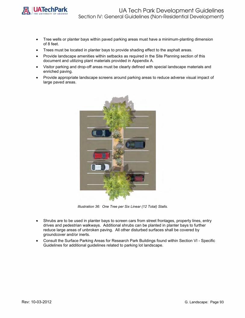
UA Tech Park Development Guidelines Section IV: General Guidelines (Non-Residential Development)
Rev: 10-03-2012 G. Landscape: Page 93
Tree wells or planter bays within paved parking areas must have a minimum-planting dimension of 8 feet.
Trees must be located in planter bays to provide shading effect to the asphalt areas. Provide landscape amenities within setbacks as required in the Site Planning section of this
document and utilizing plant materials provided in Appendix A. Visitor parking and drop-off areas must be clearly defined with special landscape materials and
enriched paving. Provide appropriate landscape screens around parking areas to reduce adverse visual impact of
large paved areas.
Illustration 36: One Tree per Six Linear (12 Total) Stalls.
Shrubs are to be used in planter bays to screen cars from street frontages, property lines, entry drives and pedestrian walkways. Additional shrubs can be planted in planter bays to further reduce large areas of unbroken paving. All other disturbed surfaces shall be covered by groundcover and/or inerts.
Consult the Surface Parking Areas for Research Park Buildings found within Section VI - Specific Guidelines for additional guidelines related to parking lot landscape.

UA Tech Park Development Guidelines Section IV: General Guidelines (Non-Residential Development)
Rev: 10-03-2012 G. Landscape: Page 94
Illustration 37: Parking Area Plan View.
G.6.0 – Open Space/Trails Landscape Several natural areas within the UA Tech Park present opportunities to utilize natural landscapes, preserve native vegetation, and protect culturally significant resources and riparian and wild habitat corridors. Areas adjacent to the Julian Wash and other significant washes within the UA Tech Park will remain in their natural state, while creating opportunities to provide passive linear park development in the form of rustic trails and nature study trails, including seating and picnicking areas. In addition, the UA Tech Park trail system provides connectivity to Pima County Trail System (see Section IV.K.). Plan walking and recreational trails to minimize conflict with other modes of circulation and design these to meet the recreational needs of identified users. In general, pedestrian and bicycle trails must be separate from one another and from vehicular traffic and conform to the following guidelines. GUIDELINES
Use decomposed granite (“dg”) or other gravel fines as the material for pedestrian trails whenever feasible.
In the Project Area of the UA Tech Park, bicycle traffic must be accommodated through use of bicycle lanes within the street rights-of-way, rather than separate paths.
Internal site pedestrian walkways must connect to the overall UA Tech Park pathway system and link to the central open space.
Consult additional guidelines provided in Chapter K: Open Space.
G.7.0 –Existing Vegetation Where possible, preserve and/or transplant existing significant native vegetation within each parcel. Significant vegetation is defined as any plant material in good physical condition over six inches in caliper. Use of existing vegetation within planting themes will help to unify park character.
Parking lot trees: one (1) tree per every six (6) linear stalls.

UA Tech Park Development Guidelines Section IV: General Guidelines (Non-Residential Development)
Rev: 10-03-2012 G. Landscape: Page 95
G.8.0 – Use of New Plant Material New or introduced plant materials should be consistent with overall park plant materials selection. Unique and ornamental plant materials should be reserved for use in focal areas only. This may occur at building entry, plazas, or signage areas. G.8.1 – Plant Palette Appendix A of this document provides the Plant Palette for the UA Tech Park. G.9.0 – Wall, Fences and Paving Patterns Use of landscape walls, fences and decorative paving patterns should be consistent with the overall character of the UA Tech Park. GUIDELINES
Use natural colors and textures in open spaces and generally low pedestrian use areas. Use more vibrant colors only in areas of concentrated pedestrian use.
G.10.0 – Landscape for the Site-wide Pedestrian and Open Space System Set exemplary environmental standards in development by clearly identifying, protecting, and preserving all culturally significant resources, and environmentally sensitive areas such as riparian corridors, washes and U.S. Army Corps of Engineers jurisdictional areas. G.11.0 – Water Conservation Measures for Landscaping and Suggested Plant Materials Conform to established and publicly accepted methods of landscape design and plant material selection in relationship to water conservation and water harvesting. In general, areas of concentrated public use such as plazas or play areas use more irrigation water and less drought tolerant plant materials than those areas which are intended for visual and aesthetics use.

UA Tech Park Development Guidelines Section IV: General Guidelines (Non-Residential Development)
Rev: 10-03-2012 H. Signage: Page 96
H. Signage Signage guidelines are intended to ensure consistent signage standards to reinforce the collective image of the UA Tech Park and its adjacent developments, while maintaining opportunities for individual identity of each development area and land use. Nonconforming or unapproved signs will be brought into conformance at the expense of the property owner. Signage design, location, size and number of signs must be in conformance with these guidelines and are subject to review and approval by the UA Tech Park Design Review Committee. Project Area must continue to use signs compatible with current practices. In addition, signs within areas designated Research Park must be compatible with those in the Project. The following general guidelines apply to all exterior signs seen from a public way, including all signs outside of buildings. H.0.0 – General Sign Guidelines Signs should contribute to the visual continuity of the entire UA Tech Park, but should be subordinate to architectural and landscape elements. Signs are intended to serve as labels, identifying address and location of businesses and activities. Information that is needed for the visitor to understand the location of business and activities should be presented in a hierarchy. GUIDELINES
Allow higher flexibility on signage for office uses. Maintain approved existing signage system within the Project as well as in Research Park
designated areas. Provide sufficient, but not excessive signage to identify the businesses associated with the facility
it occupies. Require that all permanent signs have a life expectancy of at least ten years. Materials must not
delaminate, fade, distort or deteriorate within this time period. Require that all signs meet or exceed all applicable building, electrical, mechanical, and structural
codes. Maintain all signs in good condition. Require the exposed backs of all signs visible to the public to be concealed, finished, and
properly maintained. Prohibit advertising of any kind on signs and business identification devices. Number of signs, size, location and design of each sign must not exceed the maximum limitations
for each category. No signs can be installed on or above any roofline. Signs can be internally illuminated. Animated signs require approval of the UA Office of University Research Parks Design Review
Committee. Lettering for all signs must be simple and contemporary. Size of letters on all ground signs must
be proportional to the sign area, and letters on wall signs must be proportional to the building façade.
Signs cannot be painted directly onto a building. They must be attached or surface mounted to the building.
The area of sign with individually applied letters and/or graphic symbols must be measured by a rectangle around the outside of the letters and/or symbol.
No junction boxes or exposed conduit are visible on the exterior face of a sign or building. Disconnect switches must be concealed within the sign or in other appropriate places that are out
of view. Access hatches must be concealed from view and designed as an aesthetic part of the sign.

UA Tech Park Development Guidelines Section IV: General Guidelines (Non-Residential Development)
Rev: 10-03-2012 H. Signage: Page 97
H.1.0 –Types of Signs Allowed The following types of sign are allowed in the UA Tech Park:
1. Permanent Ground Signs, which include:
a. Gateway Signs or Signature Entry Signs,
b. Secondary Entry Signs,
c. Building Identification Signs at Street Frontage,
d. Building Identification Signs On-Site; and
e. Directional Signs.
2. Building Wall Signs, which include:
a. Top of Building Signs,
b. Ground Floor Signs, and
c. Entry Door Signs.
3. Temporary Signs, which include:
a. Project/Building Marketing Signs.
4. Pole-Mounted Signs – Permitted only as traffic regulation signs.
5. Tech Park and Building Directories – Include maps and listings of buildings in special directories.
H.1.2 – Hierarchy of Signs Sign systems should be designed to lead the user from arterial and collector roadways to feeder drives, to drop-off and parking areas, and then to major building entry points. This hierarchy shall include the following types of signs:
1. Gateway Signs or Signature Entry Signs – Main identification signs within signature entry
nodes identifying major entries to the UA Tech Park at Kolb and Rita roads and at proposed I-10 interchange
2. Secondary Entry Signs – Located at secondary entrances to the UA Tech Park and at the entrances to Research Park and Residential areas.
3. Building Identification Signs at Street Frontage - Building identification at entries to primary development areas from Primary and Secondary roadways.
4. Building Identification Signs On-Site – Secondary building name identification at the entrance to a private drive serving only that building or at the drop-off area of the building.
5. Directional Signs – Limited to the identification of functions and/or services. May contain directional arrows or information such as handicapped parking, visitor parking, shipping and receiving areas.
6. Building Wall Signs – Used to identify building tenants in each development parcel. More appropriate for multi-tenant and assembly and manufacturing areas. Buildings located in the Project Area or within Research Park land uses are not allowed to have wall signs.
7. Tech Park and Building Directories – Includes maps and listings of all buildings within the UA Tech Park in special directories and building directories located inside multi-tenant buildings.
8. Pedestrian and Bicycle Pathways – Includes signs along pedestrian and bicycle pathways which provide direction to common destinations.

UA Tech Park Development Guidelines Section IV: General Guidelines (Non-Residential Development)
Rev: 10-03-2012 H. Signage: Page 98
H.2.0 – Permanent Ground Signs Provide appropriate guidelines for permanent ground signs, including: gateway signs, building identification signs at street frontage, building identification signs on-site, and directional sites. H.2.1 –Gateway Signs or Signature Entry Signs This sign type will be located at signature entries or main entrances to the UA Tech Park at Kolb and Rita roads. This is a monument sign that identifies the UA Tech Park and provides vehicular access as well as pedestrian and bicycle links to the UA Tech Park. Signature entry signs must conform to standards provided in the Circulation and Access chapter of this volume. Signature entry signs are part of the Signature Entry Boulevard. H.2.2 –Secondary Entry Signs This sign type will be located at secondary entry nodes or secondary entrances to the UA Tech Park in conformance with standards provided in the Circulation and Access chapter of this volume. H.2.3 –Building Identification Sign at Street Frontage Locate building identification signs along the street frontage by the intersections of each entry driveway with a Primary and/or Secondary streets. This sign type is limited to the identification of the building name and address. GUIDELINES
Locate building identification signs at the intersection of each driveway with a Primary or Secondary street.
Include building name and address in this sign type. Combine building addresses on a single sign where more than one building or address is
accessible from one drive. Allow one (1) identification sign per access drive. Prohibit this sign type elsewhere within the landscape setback area or along street frontages. Maximum size for this sign type should not exceed 9 square feet per face, double faced. Height
should not exceed 4 feet above grade.
Illustration 38: Building Identification Signs at Street Front.

UA Tech Park Development Guidelines Section IV: General Guidelines (Non-Residential Development)
Rev: 10-03-2012 H. Signage: Page 99
Illustration 39: Building Identification Signs at Street Front with Landscape Amenity.
H.2.4 –Building Identification Sign On-Site Locate secondary building name identification on-site at the entrance to a private drive serving the building or at the drop-off area of the building. This sign type is limited to identifying building name and address, and providing direction to one (1) facility. GUIDELINES
Sign should be integrated with the architectural style and landscape design.
Maximum size for this sign type should not exceed 9 square feet per face, double faced. Height should not exceed 4 feet above grade.
Building name identification may also be provided at the main entrance to the building.
Illustration 40: Building Identification Signs On-site.

UA Tech Park Development Guidelines Section IV: General Guidelines (Non-Residential Development)
Rev: 10-03-2012 H. Signage: Page 100
H.2.5 –Directional Signs This sign type provides direction to on-site vehicular and pedestrian traffic. GUIDELINES
Limit this sign type to the identification of functions and/or services. These signs may contain directional arrows or information such as handicapped parking, visitor
parking, shipping and receiving areas, etc.
Sign should be integrated with the architectural style and landscape design.
Maximum size for this sign type should not exceed 6 square feet per face, double faced. Height should not exceed 4 feet above grade.
Illustration 41: Directional Signs.
Illustration 42: Directional Sign with Landscape Amenity.

UA Tech Park Development Guidelines Section IV: General Guidelines (Non-Residential Development)
Rev: 10-03-2012 H. Signage: Page 101
H.3.0 – Building Wall Signs Building wall signs are used for identifying building tenants in each development parcel. This sign type is more appropriate for multi-tenant and Assembly/ Manufacturing areas or stand-alone buildings. This sign type is limited to identifying the name of a business. In addition, this sign type is not permitted on buildings located in the Project Area and/or in Research Park land uses. Building wall signs are permitted for stand-alone buildings. Three categories of building wall signs are identified:
1. Top of the Building Signs 2. Ground Floor Tenant Signs 3. Entry Door Signs
GUIDELINES
Design must be compatible with the building architecture, consistent with signage throughout the UA Tech Park, and must be determined when a conceptual building architectural plan is reviewed and approved.
Standards utilized at the time of development of the Project Area will continue to apply within that area of the UA Tech Park.
Where more than one business occupies a building, identify those buildings in a combined directory.
H.3.1 – Top of the Building Signs This sign type is restricted to the identification of a single business. Signs are located on the top floor fascia area. Only one (1) sign is permitted per building face and there should be no more than two (2) such signs per building. Signs must be internally illuminated. In addition, this sign type is not permitted on buildings located in the Project Area and/or in Research Park land uses. GUIDELINES
Size and location of this sign type must be complementary and proportional to the individual building.
Maximum size for this sign type should not exceed 75 square feet in area. Height is restricted to 34 inches. Exceptions are those on buildings with freeway frontage, maximum sign area may be increased
to 100 square feet and maximum height is 34 inches.
Illustration 43: Top of the Building Signs.

UA Tech Park Development Guidelines Section IV: General Guidelines (Non-Residential Development)
Rev: 10-03-2012 H. Signage: Page 102
H.3.2 –Ground Floor Tenant Signs This sign type is restricted to the identification of ground floor tenants. Each tenant is allowed to install one such sign at the street or parking lot frontage. In addition, this sign type is not permitted on buildings located in the Project Area and/or in Research Park land uses. GUIDELINES
Size and location of each sign must be complementary and proportional to the individual building.
Maximum size of this sign type should not exceed 32 square feet in area and not exceed 2 feet in height.
Illustration 44: Ground Floor Tenant Signs.
H.3.3–Entry Door Signs This sign type is restricted to the identification of exterior tenant entry door at multi-tenant buildings. This sign type is not permitted on buildings located in the Project Area and/or in Research Park land uses. If there is an entrance for one business only on a multi-tenant building located in the Project Area, and/or in Research Park land uses, a small entrance designation plaque identifying the business can be placed upon approval of the UA Office of University Research Parks Design Review Committee. GUIDELINES
Locate on top or immediately adjacent to the entry doors. Size and location of each sign must be complementary and proportional to the individual building. Maximum size of this sign type should not exceed 10 square feet in area, and should not exceed
18 inches in height.
Illustration 45: Entry Door Signs.

UA Tech Park Development Guidelines Section IV: General Guidelines (Non-Residential Development)
Rev: 10-03-2012 H. Signage: Page 103
H.4.0–Temporary Signs This sign type is intended to provide information and facilitate sales and leasing during the construction and marketing phase of the development parcels only. No other temporary signage is allowed. All temporary signs require design and location approvals from the UA Office of University Research Parks Design Review Committee. Project/building marketing temporary sign category identified for the Tech Park. H.4.1–Project/Building Marketing Sign This sign type includes construction signs, is limited to one (1) per street frontage, and may be approved on a case-by-case basis depending on the duration of use. Sign may include a rendering of the project and information that provides identification of uses, opening date, and names of the developer, builder, leasing agent, financing institution, general contractor, architect, and landscape architect. GUIDELINES
Maximum allowable duration of time is six months from initial occupancy. Maximum size is 60 square feet in area per face. Double face is allowed. Such signs shall not
exceed a height of 12 feet above grade and illumination is not allowed.
Illustration 46: Project/Building Marketing Signs.

UA Tech Park Development Guidelines Section IV: General Guidelines (Non-Residential Development)
Rev: 10-03-2012 H. Signage: Page 104
Illustration 47: Project/Building Marketing Sign with Permanent Landscape Amenity in Place.
H.5.0 – Pole-Mounted Signs Pole-mounted signs are only permitted as traffic regulation signs and should be consistent with existing UA Tech Park traffic regulation signs. H.6.0 – UA Tech Park and Building Directories UA Tech Park directories include maps and listings of all buildings within the UA Tech Park. These signs should be provided and must be located in areas of the UA Tech Park with high traffic of users. Examples of these areas include: Research Park, Regional Commercial, Business Development, and Commercial areas of the UA Tech Park. Building directories are located inside multi-tenant buildings in a central location, such as next to elevators. GUIDELINES
Locate UA Tech Park directories in high traffic areas providing access to vehicular, mass transit, pedestrian and bike users.
Locate UA Tech Park directories close to Information Kiosks. Provide clear directories and maps with point locators in UA Tech Park directories. Both UA Tech Park directories and building directories should provide visual continuity with the
general design of buildings. UA Tech Park directories should be made of durable materials. Locate building directories within the main lobby areas of multi-tenant buildings and/or in close
proximity to elevators and stairwells.
UA Tech Park Development Guidelines Section IV: General Guidelines (Non-Residential Development)
Rev: 10-03-2012 H. Signage: Page 105
H.7.0 – Pedestrian and Bicycle Signs Pedestrian and Bicycle Pathway signs are intended to provide directional information to pedestrian and bike users traveling inside the UA Tech Park, providing direction to common destinations. GUIDELINES
Ensure that these signs provide continuity to the overall character of the UA Tech Park. Require durable materials for the construction of these signs.
H.8.0 – Additional Guidelines to all Sign Categories: Adhere to additional guidelines for all sign categories provided below. GUIDELINES
Building signs shall be attached or surface mounted to the building. Sign composition shall consist of individually illuminated letters. Boxes with lighting inside are not permitted. Individual lettering can be internally illuminated, or lit with backlighting. Metal and acrylic are recommended materials for building signs. Wood signs are not permitted. Colors of lettering must be complementary with exterior building materials and are subject to
review by the UA Office of University Research Parks Design Review Committee. A business logo is permitted on the building wall signs as long as the total sign area and sign
height do not exceed the maximum allowable size. The lettering for all building signs per individual building must be of one selected style. Such style
must be reviewed and approved by the UA Office of University Research Parks Design Review Committee.
H.9.0 – Prohibited Signs The following types of signs are not permitted in the UA Tech Park:
Signs that obstruct view and/or free access of pedestrian or vehicular traffic. Signs that project above a parapet or roofline of a building. Signs or graphics painted directly on exterior of buildings. Sign graphics painted on or adhered to trash bins or their enclosures. Any sign placed or displayed on a vehicle parked primarily for the purpose of displaying the sign. Signs, which identify a business not on the property. Temporary signs beyond approved period of display. Any sandwich board “A” frame sign or other portable sign require approval of the UA Office of
University Research Parks Design Review Committee. Signs consisting of banners, pennants, ribbons, streamers, stings of light bulbs and spinners
(except during holiday season or special thematic events approved by the UA Office of University Research Parks Design Review Committee).
Brashly colored signs with moving or flashing lights; signs which are animated in any manner require approval of the UA Office of University Research Parks Design Review Committee.
Off-premise signs referring to a business or merchant not doing business on the premise where the sign is displayed.
UA Tech Park Development Guidelines Section IV: General Guidelines (Non-Residential Development)
Rev: 10-03-2012 H. Signage: Page 106
H.10.0 – Sign Location A sign shall not be located:
Within a public right-of-way or on public property.
Within 20 feet of a street corner or as to interfere with traffic visibility across the corner.
So as to obstruct the view of a motorist entering a road from a parking area, alley or other vehicular access point.
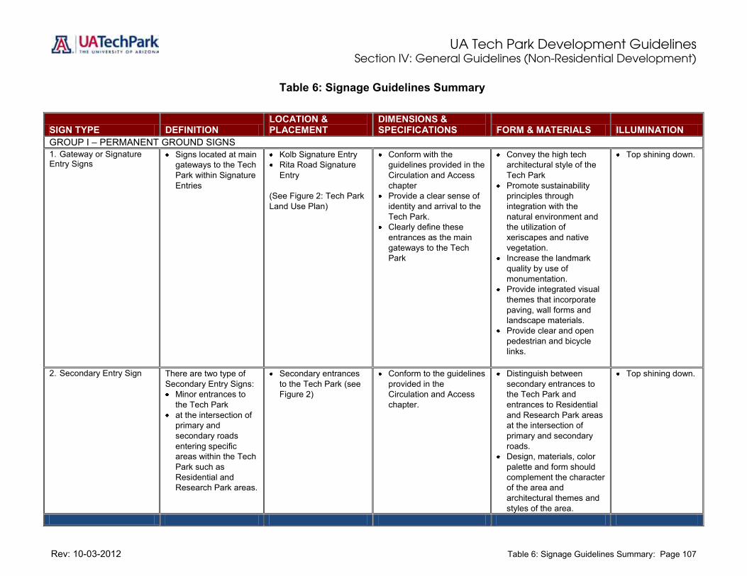
UA Tech Park Development Guidelines Section IV: General Guidelines (Non-Residential Development)
Rev: 10-03-2012 Table 6: Signage Guidelines Summary: Page 107
Table 6: Signage Guidelines Summary
SIGN TYPE DEFINITION LOCATION & PLACEMENT
DIMENSIONS & SPECIFICATIONS FORM & MATERIALS ILLUMINATION
GROUP I – PERMANENT GROUND SIGNS 1. Gateway or Signature Entry Signs
Signs located at main gateways to the Tech Park within Signature Entries
Kolb Signature Entry Rita Road Signature
Entry (See Figure 2: Tech Park Land Use Plan)
Conform with the guidelines provided in the Circulation and Access chapter
Provide a clear sense of identity and arrival to the Tech Park.
Clearly define these entrances as the main gateways to the Tech Park
Convey the high tech architectural style of the Tech Park
Promote sustainability principles through integration with the natural environment and the utilization of xeriscapes and native vegetation.
Increase the landmark quality by use of monumentation.
Provide integrated visual themes that incorporate paving, wall forms and landscape materials.
Provide clear and open pedestrian and bicycle links.
Top shining down.
2. Secondary Entry Sign There are two type of Secondary Entry Signs: Minor entrances to
the Tech Park at the intersection of
primary and secondary roads entering specific areas within the Tech Park such as Residential and Research Park areas.
Secondary entrances to the Tech Park (see Figure 2)
Conform to the guidelines provided in the Circulation and Access chapter.
Distinguish between secondary entrances to the Tech Park and entrances to Residential and Research Park areas at the intersection of primary and secondary roads.
Design, materials, color palette and form should complement the character of the area and architectural themes and styles of the area.
Top shining down.

UA Tech Park Development Guidelines Section IV: General Guidelines (Non-Residential Development)
Rev: 10-03-2012 Table 6: Signage Guidelines Summary (continued): Page 108
Table 6: Signage Guidelines Summary (continued)
SIGN TYPE DEFINITION LOCATION & PLACEMENT
DIMENSIONS & SPECIFICATIONS FORM & MATERIALS ILLUMINATION
GROUP I – PERMANENT GROUND SIGNS 3. Building Identification Signs at Street Front
Signs that identify the building name and address.
Located on the street front by the intersections of entry driveways and public streets.
Limited to one sign per access drive.
Maximum sign area: 9 sq. ft. per face, double faced.
Maximum height: 4 ft. above finish grade.
More than one building name may be identified on one sign.
Freestanding sign on a concrete base.
Form and materials must relate to architectural style of project.
Wood signs are not permitted.
Top shining down.
4. Building Identification Signs On-Site
Signs that identify building names and addresses and provide direction to such facilities.
Located on-site adjacent to internal access drives and in parking areas.
Maximum sign area: 9 sq. ft. per face, double faced.
Maximum height: 4 ft. above finished grade.
More than one building name may be identified on one sign.
Freestanding sign on a concrete base.
Form and materials must relate to architectural style of project.
Wood signs are not permitted.
Top shining down.
5. Directional Signs Signs that provide direction to on-site vehicular and pedestrian traffic.
Limited to the identification of functions and/or services but not the name of the business.
Located on-site adjacent to internal access drives, parking areas, and pedestrian walkways.
Maximum sign area: 6 sq. ft. per face, double faced.
Maximum height: 4 ft. above finished grade.
Such sign may contain directional arrows or information such as visitor parking, shipping and receiving, etc.
Freestanding sign on a concrete base or panel sign mounted on posts.
Form and materials must relate to architectural style of project.
Wood signs are not permitted.
Top shining down.

UA Tech Park Development Guidelines Section IV: General Guidelines (Non-Residential Development)
Rev: 10-03-2012 : Page 109
Table 6: Signage Guidelines Summary (continued)
SIGN TYPE DEFINITION LOCATION & PLACEMENT
DIMENSIONS & SPECIFICATIONS FORM & MATERIALS ILLUMINATION
GROUP II – BUILDING WALL SIGNS 1. Top of the Building Signs Signs that identify a
single business. This sign type is
prohibited in Project Area and in Research Park land Uses.
Located on the top floor fascia area.
Limited to one sign per building face.
No more than two such signs per building.
Maximum sign area: 75 sq. ft.
Buildings with freeway frontage, maximum sign area is 100 sq. ft.
Maximum height: 34 in. Size and location of each
sign shall be complementary and proportional to individual buildings.
Individual letters attached or surface mounted to the building wall, metal, fiberglass or acrylic.
Wood signs are not permitted.
Halo lit or interior illuminated.
Animation requires Design Review Committee approval.
2. Ground Floor Tenant Signs
Signs restricted to the identification of ground floor tenants.
This sign type is prohibited in Project Area and in Research Park land Uses.
Located on the top area of ground floor building façade.
Limited to one sign per ground floor tenant.
Maximum sign area: 32 sq. ft.
Maximum height: 2 ft. Size and location of each
sign must be complementary and proportional to individual buildings.
Individual letters attached or surface mounted to the building wall, metal, fiberglass or acrylic.
Wood signs are not permitted.
Halo lit or interior illuminated.
Animation requires Design Review Committee approval.
3. Entry Door Signs Signs restricted to the identification of exterior tenant entry doors.
This sign type is prohibited in Project Area and in Research Park land Uses (see Guidelines).
Located on top or immediately adjacent to the entry doors.
Limited to one sign per ground floor tenant.
Maximum sign area: 10 sq. ft.
Maximum height: 18 in. Size and location of each
sign must be complementary and proportional to individual buildings.
Individual letters attached or surface mounted to the building wall, metal, fiberglass or acrylic.
Wood signs are not permitted.
Halo lit or interior illuminated.
Animation requires Design Review Committee approval.

UA Tech Park Development Guidelines Section IV: General Guidelines (Non-Residential Development)
Rev: 10-03-2012 Table 6: Signage Guidelines Summary (continued): Page 110
Table 6: Signage Guidelines Summary (continued)
SIGN TYPE DEFINITION LOCATION & PLACEMENT
DIMENSIONS & SPECIFICATIONS FORM & MATERIALS ILLUMINATION
GROUP III – TEMPORARY GROUND SIGNS 1. Project / Building Marketing Signs
Signs that identify uses and information for new projects and facilitate sales and leasing during the construction and marketing phase of a development parcel.
One sign per street front.
Signs must be removed once the building and/or tenant improvements have received a certificate of occupancy.
Maximum allowable duration of time for such sign is six (6) months from initial occupancy.
Maximum sign area: 60 sq. ft.
Double face is allowed. Maximum height: 12 ft.
above finish grade. Signs may include
rendering of the project, identification of the developer, sales/leasing agent, architect, landscape architect, general contractor, opening dates, etc.
Panel sign with a post supporting each end of the sign.
No illumination allowed.

UA Tech Park Development Guidelines Section IV: General Guidelines (Non-Residential Development)
Rev: 10-03-2012 I. Site Furnishings: Page 111
I. Site Furnishings Major site furnishings include fences, walls, light poles, benches, waste receptacles, water fountains and planters. In general, visual continuity of these elements is desired throughout the UA Tech Park. Variation from the norm is welcomed in some areas particularly in areas with special character such as public areas located in the Park Plaza, Research Park, Business Development, Regional Commercial and Hospitality areas. Also see Section G. Landscape and Section J. Lighting for additional standards and guidelines. I.1.0 – Minimum Furnishing Requirements within Public Areas with High Pedestrian Traffic Public areas with high pedestrian traffic within the UA Tech Park should contain, at a minimum, the site furniture included in the following guidelines. GUIDELINES Two (2) litter receptacles. One (1) drinking fountain. Twenty-four (24) linear feet of bench seating area. Shading structure having a dual purpose providing shade and serving as public art.
Examples of High-Tech Shading Structures Serving as Public Art

UA Tech Park Development Guidelines Section IV: General Guidelines (Non-Residential Development)
Rev: 10-03-2012 J. Lighting: Page 112
J. Lighting Lighting is an important element enhancing nighttime ambience for the UA Tech Park. It also provides for the safety and security of pedestrians and vehicular traffic while preserving the unique desert environment through protection of access to the dark night sky. Intended outcomes include continuing support of astronomical activity and minimizing wasted energy, while not compromising the safety, security, and wellbeing of persons engaged in outdoor night time activities. Lighting fixtures must be of contemporary design, complement the building architecture, and reinforce the overall “high-tech” image of the UA Tech Park. On-site lighting fixtures must be consistent with respect to style, materials, colors and spacing in order to ensure identity and unity throughout the project. Street lighting must be the same as adjacent developments to achieve a uniform visual environment off-site. All lighting design and location must be reviewed by the UA Office of University Research Parks Design Review Committee. Due to the proximity of the project site to the airport and air base, lighting design must also meet all applicable Federal Aviation Administration regulations pertaining to safety standards for airport operation, and applicable County and City standards. J.1.0 – Fixtures (Luminaries) Lighting fixtures should contribute to the visual continuity of development and be used in a consistent manner throughout the UA Tech Park, have a durable finish and their design must meet all applicable Federal Aviation Administration regulations pertaining to safety for airport operation.
GUIDELINES A consistent theme for the lighting fixtures within the streetscapes and common areas of the UA Tech
Park is required. Safety, security and daytime appearance should be the primary design considerations. Lighting should be fully shielded horizontal lamps so that no fugitive light may escape beyond the
property/parcel line. No light source should be visible from the site perimeter. Fixture style and design should be compatible and consistent with the lighting design of other projects
within the UA Tech Park. The pattern of light pooling from each fixture should avoid glare or reflection on adjacent properties,
buildings, or roadways. Exterior lighting fixtures should relate stylistically to the architecture of the adjacent building. Lighting fixtures must be designed to minimize light pollution.
J.2.0 – Street Lighting Street lighting fixtures must match lighting fixtures in the UA Tech Park and in adjacent developments to achieve a uniform visual environment on-site and off-site.

UA Tech Park Development Guidelines Section IV: General Guidelines (Non-Residential Development)
Rev: 10-03-2012 J. Lighting: Page 113
GUIDELINES Street lighting fixtures on Park roads must also match or complement those of existing UA Tech Park
development. Street lighting fixtures along Kolb and Rita roads must match or complement those of adjacent
development. Minimum mounting height is 25 feet. Maximum mounting height is 30 feet. Luminaries and poles shall have a durable finish. Park poles are currently bronze in color. Pole colors shall be approved by the UA Office of University
Research Parks Design Review Committee.
Illustration 48: Primary and Secondary Street Lighting.
J.3.0 – General On-Site Lighting On-site lighting includes vehicular circulation and parking area lighting, pedestrian area lighting, architectural lighting, service area lighting, accent lighting, and security and special effects.
GUIDELINES
On-site lighting must convey a cohesive image throughout the UA Tech Park and must adhere to all applicable Federal Aviation Administration regulations pertaining to safety standards for airport operation.
All exterior on-site lighting must be focused, directed, and arranged to prevent glare and illumination on public streets and adjoining properties.
All exterior on-site lighting must be shielded and focused to minimize spill light into the night sky. Lighting fixtures are to be of contemporary design. Lights must be constructed of vandal proof materials, and recessed, or otherwise designed to reduce
potential problems associated with damage and replacement of fixtures. Lighting elements may have controls to allow their selective use as an energy conservation measure. Exterior lighting designs must develop a hierarchy by varying heights and fixtures. This defines the
organization of pedestrian and vehicular circulation patterns. Creative lighting design should be placed at focal areas such as entrances (both pedestrian and
vehicular), plazas and courtyards to provide a sense of place and arrival. Parking areas, pedestrian walks, and building entrances must be well lighted for security purposes. Service area lighting must be contained within the service yard boundaries and enclosure walls. Light
sources must not be visible from the street. To achieve accurate landscape rendering, the luminaries must be of metal halide.
Parcel/Property line or Right-of-Way (ROW)
30’ Max.
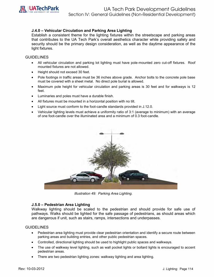
UA Tech Park Development Guidelines Section IV: General Guidelines (Non-Residential Development)
Rev: 10-03-2012 J. Lighting: Page 114
J.4.0 – Vehicular Circulation and Parking Area Lighting Establish a consistent theme for the lighting fixtures within the streetscape and parking areas that contributes to the UA Tech Park’s overall aesthetics character while providing safety and security should be the primary design consideration, as well as the daytime appearance of the light fixtures.
GUIDELINES All vehicular circulation and parking lot lighting must have pole-mounted zero cut-off fixtures. Roof
mounted fixtures are not allowed. Height should not exceed 30 feet. Pole footings in traffic areas must be 36 inches above grade. Anchor bolts to the concrete pole base
must be covered with a sheet metal. No direct pole burial is allowed. Maximum pole height for vehicular circulation and parking areas is 30 feet and for walkways is 12
feet. Luminaries and poles must have a durable finish. All fixtures must be mounted in a horizontal position with no tilt. Light source must conform to the foot-candle standards provided in J.12.0. Vehicular lighting levels must achieve a uniformity ratio of 3:1 (average to minimum) with an average
of one foot-candle over the illuminated area and a minimum of 0.3 foot-candle.
Illustration 49: Parking Area Lighting.
J.5.0 – Pedestrian Area Lighting Walkway lighting should be scaled to the pedestrian and should provide for safe use of pathways. Walks should be lighted for the safe passage of pedestrians, as should areas which are dangerous if unit, such as stairs, ramps, intersections and underpasses.
GUIDELINES Pedestrian area lighting must provide clear pedestrian orientation and identify a secure route between
parking areas and building entries, and other public pedestrian spaces. Controlled, directional lighting should be used to highlight public spaces and walkways. The use of walkway level lighting, such as wall pocket lights or bollard lights is encouraged to accent
pedestrian areas. There are two pedestrian lighting zones: walkway lighting and area lighting.

UA Tech Park Development Guidelines Section IV: General Guidelines (Non-Residential Development)
Rev: 10-03-2012 J. Lighting: Page 115
1. Walkway lighting must be zero cut-off type. 2. Poles must not exceed 12 feet in height. 3. Both luminaries and poles must have a durable finish. 4. Area lighting includes building entries and other public plazas and courtyards.
Illustration 50: Pedestrian Walkway Lighting.
Building entries can be illuminated with soffit, bollard, step or other comparable lighting. Plazas, courtyards, paths and seating areas must be lighted to ensure pedestrian safety and security.
A variety of lighting types may be used for interest and special effects that would reflect or enhance the character and function of the area.
Concrete bollards used for pedestrian areas must not exceed 42 inches in height. Lighting fixtures should relate stylistically to the architecture of adjacent buildings.
Illustration 51: Bollard Lighting.
Concrete bollard should not exceed 42 inches in height

UA Tech Park Development Guidelines Section IV: General Guidelines (Non-Residential Development)
Rev: 10-03-2012 J. Lighting: Page 116
Steps, ramps, and seating walls must be illuminated with built-in fixtures wherever possible. Pedestrian area lighting must utilize subdued warm-white mercury or incandescent lamps. Pedestrian area lighting must achieve a uniformity ratio of 3.5 to 1 (average to minimum), with an
average illumination of 0.6 foot-candle and a minimum of 0.18 foot-candle. J.6.0 – Architectural Lighting Encourage special lighting that accents building features and creates visual interest while preventing excessive outdoor lighting, provided that overall continuity is maintained throughout the UA Tech Park.
GUIDELINES Exterior architectural lighting must preserve the unique desert environment through protection of
access to the dark night sky. Minimize the obtrusive aspects of excessive outdoor lighting usage by shielding light fixtures in such
a manner that no lamp or vertical element of a lens or diffuser is visible from off site. Total outdoor light output should not exceed one hundred (100) percent of the lumens from outdoor
light fixtures installed on grade, on poles, and installed on tops or sides of buildings or other structures.
Full cut-off light fixtures should be installed under canopies, building overhangs, or roof eaves in such a manner that no lamp or vertical element of a lens or diffuser is visible from off-site.
Flood or spot lamps must be aimed no higher than 45 degrees to the horizontal when the source is visible from any adjacent residential properties.
All exterior architectural lighting must utilize indirect or hidden light sources. Allowable lighting includes wall washing, overhead down lighting and interior lighting that spill outside. All exterior lighting fixtures should relate stylistically to the architecture of adjacent buildings.
Illustration 52: Illumination from Building.
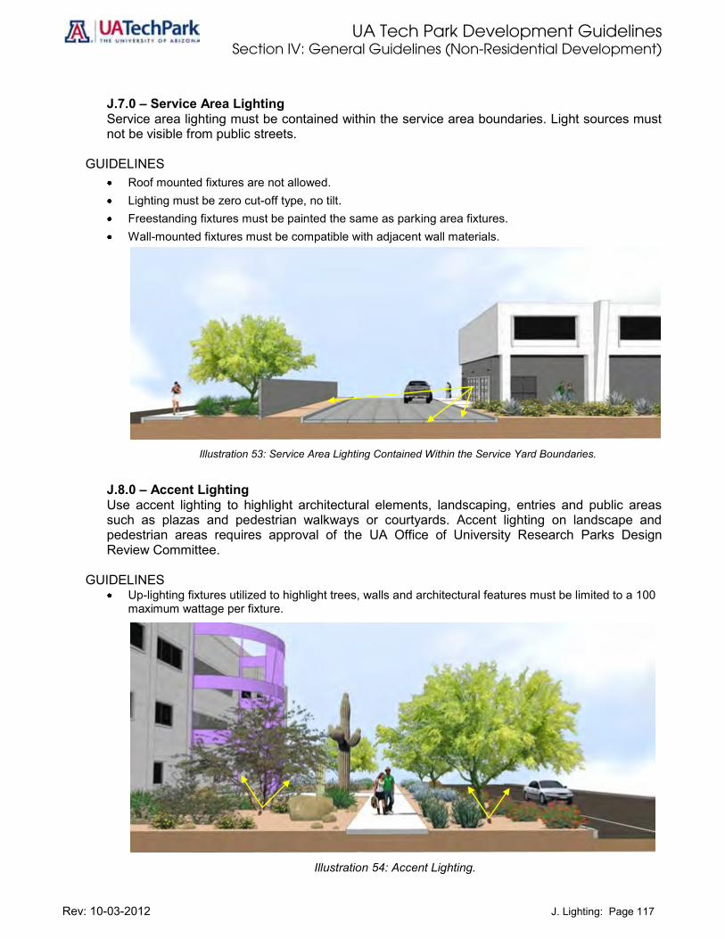
UA Tech Park Development Guidelines Section IV: General Guidelines (Non-Residential Development)
Rev: 10-03-2012 J. Lighting: Page 117
J.7.0 – Service Area Lighting Service area lighting must be contained within the service area boundaries. Light sources must not be visible from public streets.
GUIDELINES Roof mounted fixtures are not allowed. Lighting must be zero cut-off type, no tilt. Freestanding fixtures must be painted the same as parking area fixtures. Wall-mounted fixtures must be compatible with adjacent wall materials.
Illustration 53: Service Area Lighting Contained Within the Service Yard Boundaries.
J.8.0 – Accent Lighting Use accent lighting to highlight architectural elements, landscaping, entries and public areas such as plazas and pedestrian walkways or courtyards. Accent lighting on landscape and pedestrian areas requires approval of the UA Office of University Research Parks Design Review Committee.
GUIDELINES Up-lighting fixtures utilized to highlight trees, walls and architectural features must be limited to a 100
maximum wattage per fixture.
Illustration 54: Accent Lighting.

UA Tech Park Development Guidelines Section IV: General Guidelines (Non-Residential Development)
Rev: 10-03-2012 J. Lighting: Page 118
J.9.0 – Security Lighting Security lighting should not negatively impact adjacent users. J.10.0 – Parking Garage Lighting Parking garage lighting should provide security and safe maneuvering without creating harsh glare to areas outside the structure and comply with safety and visibility guidelines provided in E.6.0.
J.11.0 – Sign Lighting Sign illumination should complement rather than overpower the image of the building and its immediate landscape and should comply with standards and guidelines provided in Chapter H, Signage. J.12.0 –Light Intensity The light intensity levels around the UA Tech Park should vary in response to people-use and potential hazards. The levels of illumination provided in the following table should be maintained for each of the specific locations:
Table 7: Levels of Illumination
Specific Locations Level of Illumination
Building Entrances 5.0 Sidewalks 2.0 Bikeways 1.0
Courts/Plazas 1.5
Ramps 5.0 Stairways 5.0 Underpasses 5.0 Waiting Areas 1.0 Parking Lots 1.0 Roadways 1.5
Note: Values given above are the minimum average maintained horizontal foot-candles which are measured at the average point of illumination between brightest and darkest areas 4 to 5 feet above the ground surface.
UA Tech Park Development Guidelines Section IV: General Guidelines (Non-Residential Development)
Rev: 10-03-2012 J. Lighting: Page 119
J.13.0 –Prohibited Lights and Light Fixtures The following lights and light fixtures are prohibited in the UA Tech Park:
1. Mercury vapor lamp fixtures and lamps for outdoor lighting;
2. Low pressure sodium, high pressure sodium, metal halide, fluorescent, quartz or incandescent outdoor lighting fixtures or lamps;
3. The use of laser source light or any other similar high intensity light for outdoor advertising, when projected above the horizontal; and
4. The operation of searchlights for advertising purposes.

UA Tech Park Development Guidelines Section IV: General Guidelines (Non-Residential Development)
Rev: 10-03-2012 K. Open Space: Page 120
K. Open Space Open space at the UA Tech Park should provide for a mix of riparian habitat, stormwater drainage channels and recreational amenities. Wildlife corridors and riparian zones must be maintained and enhanced “in place,” while recreational amenities may be developed along their outer edges. This mix of uses allows for the preservation of environmentally sensitive areas and the development of active and useable landscape amenities. Recreational activities within open space areas may include picnicking, jogging and walking trails, bike trails, children’s play grounds, golf and basketball and tennis courts. Throughout the UA Tech Park, the minimum required open space is 25% of the gross lot area. In addition, the UA Tech Park Master Plan designates 136 acres as Davis-Monthan AFB Dedicated Open Space, 215 acres as Open Space/Golf Course, and 5 acres as Science Park Drive Multi-Use Path as shown on Figure 2. K.1.0 – Riparian Corridors Riparian corridors within open space areas enhance the park-like nature of the UA Tech Park and must be actively utilized to serve several utilitarian purposes. Wildlife corridors and riparian zones must be maintained and enhanced “in place,” while recreational amenities, such as linear parks, may be developed along the outer edges.
GUIDELINES Provide interconnectivity and landscape amenities between land uses, linear parks and other
recreational amenities. Support the scenic quality of the UA Tech Park along primary and secondary roads. Preserve and protect riparian and wildlife corridors and culturally significant resources. Support an environment in which native desert wildlife can coexist with UA Tech Park development. Encourage development patterns to grow with the natural grade of the land, utilizing existing drainage
and topography. Provide space for both formal and informal recreational amenities.
K.2.0 – Floodplains and Riparian Areas Development of the UA Tech Park must maintain the integrity of its floodplains and riparian corridors and avoid encroachment on floodplains and riparian corridors. These open space areas should be utilized as pedestrian linkages, wildlife corridors, nature study trails and passive recreation.
GUIDELINES Avoid encroachment on floodplains and riparian corridors. Take advantage of floodplains and riparian corridors by utilizing them as open space, pedestrian
linkages, wildlife corridors and recreational areas to enhance the sites park-like qualities. Utilize flood control practices and storm water channelization within the riparian zones. Employ
environmentally sensitive engineering methods, landscape amenities, building setbacks and grading limits to guide development adjacent to riparian zones to maintain and enhance the quality of the natural environment and to provide adequate floodway flows.

UA Tech Park Development Guidelines Section IV: General Guidelines (Non-Residential Development)
Rev: 10-03-2012 K. Open Space: Page 121
K.3.0 – Archaeological Sites Development of the UA Tech Park must respect culturally significant sites by preserving, protecting and/or restoring them. Providing pedestrian linkages to these sites as part of the overall circulation plan is recommended. Plaques identifying archaeological period, cultures represented and so on may add to the preservation purpose while providing an enriching recreational experience.
GUIDELINES Prohibit buildings and or structures on the UA Tech Park’s ten archaeological sites. Provide landscape amenities between sensitive cultural resources and new development. Maintain the integrity of culturally significant sites by preserving, protecting and/or restoring them. Provide linkages to trail system and directional signs for pedestrian/bicycle users. Provide clear signage for equestrian trails.
K.4.0 – Open Space/Golf Course The UA Tech Park Land Use Plan identifies an Open Space/Golf Course land use. This land use designation is compatible with the Davis-Monthan AFB 0-30,000 ft. ADC, provided that the club house is located outside of the 0-30,000 feet ADC. The following development standards and design guidelines apply.
GUIDELINES Require that golf course design incorporates the natural landscape and riparian areas while
minimizing intrusion into the natural surrounding vegetation and minimize water usage through the utilization of reclaimed water and water harvesting techniques where appropriate.
Minimize water usage through the utilization of reclaimed water and water harvesting techniques where appropriate.
Utilize the natural landscape setting to the greatest degree feasible. Minimize intrusion into the natural surrounding vegetation. Fairways must be kept to a minimum, except at normal driving distances. Areas of the “rough” adjacent to greens must be natural vegetation and should not be covered with turf. Greens must be kept to a minimum size feasible, with liberal use of sand traps and other naturally
occurring hazards. Cart paths, fairways, and rough areas must be of minimal width, revegetated or enhanced according
to the re-vegetation guidelines provided in the following section. K.5.0 – Revegetation Establish revegetation guidelines that include the utilization of native plant vegetation and water harvesting techniques.
GUIDELINES Utilize native plant materials and/or a native seed mix for revegetation. Utilize water conservation irrigation techniques until plantings are established. Disturbed washes within the UA Tech Park shall be revegetated to restore them to a natural
appearance. Riparian plantings shall include recommended species listed in Appendix A: UA Tech Park Plant List.

UA Tech Park Development Guidelines Section IV: General Guidelines (Non-Residential Development)
Rev: 10-03-2012 K. Open Space: Page 122
K.5.1 – Desert Vegetation Encourage the use of environmentally sensitive development and maintenance practices.
GUIDELINES Use trees, shrubs, cacti and other plants that are native to the Arizona-Sonora desert region for
landscape purposes. When developing new building sites, minimize the disturbance of cacti and other existing desert
vegetation. Relocate significant native vegetation when feasible. Plant landscapes developed for only aesthetic purposes with native and/or drought tolerant materials. Use reclaimed water to irrigate lawn and other non-vegetative, active landscapes.
K.6.1 – Linear Park Include a multimodal linear park system along Julian Wash and Science Park Drive Multi-Use Path with connecting trails providing connectivity to the following areas: The Kolb and Rita Road main gateways or signature entrances to the UA Tech Park Internal and perimeter pedestrian, bicycle, and trail systems of the UA Tech Park Golf course and other recreational amenities serving the UA Tech Park The UA Tech Park Center The UA Solar Zone Pima County Regional Trail System.
GUIDELINES
Provide trail access points for trails identified in the Pima County Master Trail System. Provide clear trail heads at the major entrances to the UA Tech Park on Rita Road and Kolb Road. Provide connectivity between the UA Tech Park trail system, the golf area, major recreational
facilities, the Julian Wash Regional Trail System, the Vail Academy and High School, the UA Solar Zone, the UA South Campus and the different land uses within the UA Tech Park.
Develop a trail-use signage system that provides visual identification, using symbols, shapes, etc., to clarify lane or direction of movement on multiple-use trails, level of trail difficulty, trail length, and direction and trail length to access point with identified Pima County trails.
Design trails and their associated facilities in a manner that is sensitive to natural settings and retain natural appearances and values.
Require the minimum alterations necessary to encourage public use and to protect natural and cultural resources.
Incorporate sensitivity to wildlife habitats designated as critical or sensitive and to cultural resources. Balance specific types and levels of use with ways to preserve and protect open space. Design trails as to enhance the visual experience of users while preserving their natural scenic
quality. Install barriers to unauthorized motor vehicle use where needed. These designed deterrents should
be supplemented by signage and a management and enforcement program. Barriers should not impede access for maintenance purposes.
Integrate interpretive programs on wildlife, natural history, and cultural resources into the trail experience. Interpretive programs and design will depend on the trail environment, anticipated users, and volume of use.
Take into consideration the unique qualities and needs of Pima County when designing trails, trail facilities and trail management programs.
Trails should be designed for easy and low cost maintenance.

UA Tech Park Development Guidelines Section IV: General Guidelines (Non-Residential Development)
Rev: 10-03-2012 Figure 4: UA Tech Park Conceptual Trail System: Page 123
Figure 5: UA Tech Park Conceptual Trail Park System

UA Tech Park Development Guidelines Section IV: General Guidelines (Non-Residential Development)
Rev: 10-03-2012 K. Open Space: Page 124
Illustration 55: Rita Road Multiuse Path Trail System Concept
(UA Tech Park Perimeter Trail System)
Illustration 56: YMCA Park Concept along Rita Road Multiuse Path Trail
(UA Tech Park Perimeter Trail System)

UA Tech Park Development Guidelines Section IV: General Guidelines (Non-Residential Development)
Rev: 10-03-2012 K. Open Space: Page 125
Illustration 55: Interpretive Interactive Solar Technology Demonstration Trail Node Concept for Solar Zone Trail
Along the East Perimeter of the UA Solar Zone Connecting Science Park Drive and the Julian Wash Regional Trail System (UA Tech Park Internal Trail System)
Illustration 56: Interpretive Interactive Solar Technology Node Concept Details (Perspective and Plan Views)

UA Tech Park Development Guidelines Section IV: General Guidelines (Non-Residential Development)
Rev: 10-03-2012 L. Information Kiosks: Page 126
L. Information Kiosks Information Kiosks are standalone devices combining a number of computer peripheral technologies such as a keyboard, video display, touch screen, magnetic card reader, and image/document scanner to collect and dispense information and services. These technologies are packaged in a rugged and moderately secure case approximately the size of a phone booth.
L.1.0 – Information Kiosks Location Locate information kiosks throughout the UA Tech Park in areas that are easily accessible to all users and/or areas with high congregation users, such as Business Development II and Regional Commercial and Hospitality areas. Information kiosks areas should be properly illuminated and safe.
GUIDELINES
Position information kiosk to avoid glare from lighting and sunlight. Locate information kiosks close to building entrance areas and parking facilities to allow easy access. Locate kiosks in areas with large congregations of people such as the Business Development II and
Commercial and Hospitality areas. Provide bicycle racks close to information kiosk to facilitate access for bicycle users. Locate information kiosks in well-lighted areas to provide higher security. Provide easy access to wheelchair users. Provide a variable height terminal. Screen location may cause problems for either tall users or
persons in a wheelchair interacting from a lower position, especially when screens are at an angle. Enhance feedback by using illumination, sound in the form of 'beeps' or 'clicks' or tactile feedback,
which lets the user feel that a button has been activated. Select appropriate typeface. The choice of typeface can significantly affect legibility, particularly for
users with low vision. Touch screens should have large fields to help persons with poor manual dexterity. Smart cards can store special instructions, e.g. telling the terminal to display large type, deliver
speech output or the preferred language of the user.

UA Tech Park Development Guidelines Section IV: General Guidelines (Non-Residential Development)
Rev: 10-03-2012 Wireless Communication Facilities: Page 127
M. Wireless Communication Facilities Wireless communication facilities are allowed within the UA Tech Park; however, the visual impact of these facilities should be minimized by architecturally integrating them with proposed buildings, structures, and landscaping. M.1.0 –Installation, Improvements and Maintenance Wireless communication facility installation, improvements and maintenance shall comply with all the following standards and guidelines.
GUIDELINES
Comply with all applicable Federal Aviation Administration regulations and Davis-Monthan AFB standards related to the safe operation of aircraft.
Be maintained and operated in accordance with all applicable FCC rules and regulations with respect to environmental effects of electromagnetic emissions.
Be lighted and/or painted in accordance with any applicable rules and regulations of the Federal Aviation Administration.
Comply with all applicable standards and regulations set forth in the Uniform Building Code, the National Electrical Code, the Uniform Plumbing Code, the Uniform Mechanical Code, the Uniform Fire Code, and structural standards of the Electronic Industries Association.
Conform to all other applicable development standards and guidelines provided in this Development Guidelines volume.
Maximum height for a co-located facility should comply with all regulations pertaining to the safe operation of aircrafts and be approved by the UA Office of University Research Parks Design Review Committee.
Antenna, if used, shall be integrated into the building architecture. Free-standing cell towers, antenna, or roof mounted wireless telecommunications facilities are
permitted in the UA Tech Park, upon UA Office of University Research Parks Design Review Committee approval.
M.1.1 – Permitted Height The maximum permitted height for any wireless communication facility and/or cell tower located within the Davis-Monthan AFB 0-30,000 feet ADC shall not exceed 62 feet in height, measured from grade.
M.1.2 – Telecommunication Tower Spacing Telecommunication towers shall be located at least 2 miles from other telecommunication towers and no closer than a quarter mile to the perimeter line of any residential district based upon a survey of surrounding sites using GPS or other methods provided by the applicant. M.1.3 – Tower and Antenna Design and Appearance Requirements Tower and Antenna design and appearance shall support the overall “high tech” identity of the UA Tech Park, comply with all applicable standards and guidelines provided in section and require UA Office of University Research Parks Design Review Committee approval. No tower or antenna shall be installed, improved or modified, until the UA Office of University Research Parks Design Review Committee finds that the development standards and design guidelines provided in this section have been met. Both proposed or modified towers and antennas shall meet the following design and appearance requirements.

UA Tech Park Development Guidelines Section IV: General Guidelines (Non-Residential Development)
Rev: 10-03-2012 Wireless Communication Facilities: Page 128
GUIDELINES Towers and antennas must blend into the surrounding environment and reflect the overall “high-tech”
identity of the UA Tech Park.
Stealth or concealment technology may be required where appropriate.
Guyed towers are prohibited.
Commercial wireless telecommunication towers shall be of a monopole design unless the UA Office of University Research Parks Design Review Committee determines that an alternative design would better blend into the surrounding environment.
Use of polarized antennas which electronically combine the functions of transmit and receive antennas (rather than spatial diversity antenna arrays which rely on antennas being physically separated) and dual-band/multi-band antennas (allowing two or more providers of different types of commercial wireless services to share a common antenna) is encouraged.
Antennas shall be mounted on telecommunication towers so as to present the smallest possible silhouette, profile, or cross-section. Preferred antenna mounting may include:
o Compact polarized antennas in a cylindrical unicell arrangement less than 22 inches in diameter mounted atop the tower;
o Panel antennas flush-mounted against the tower;
o Antennas mounted at the end of straight or curved davit arms or brackets extending from the sides of the tower.
No telecommunication tower shall have constructed thereon, or attached thereto, in any way, any platform, catwalk, crow's nest, triangular framework, climbing devices (within the first 20 feet), or like structures or equipment, except during periods of construction or repair. Curved or straight davit arms or brackets used for antenna mounting shall be connected to the tower at the base of the arms or brackets only and such arms or brackets (and any antennas or hardware mounted thereon) shall not be physically inter-connected with any similar arm or bracket.
All equipment enclosures and other improvements accessory to a tower shall be architecturally designed to blend in with the identity of the UA Tech Park and shall be maintained in good appearance and repair.
No equipment enclosure may exceed ten (10) feet in height.
Ground mounted equipment shall be screened from view by suitable vegetation, except where a design of non-vegetative screening better reflects and complements the architectural character of the surrounding buildings and areas.
To the greatest extent possible, wireless telecommunication facilities shall be designed to survive a natural disaster and wind shear without interruption in operation.
Telecommunication towers, equipment enclosures and other improvements shall be enclosed within a security fence consisting of chain link fencing at least eight (8) feet in height. The fence shall not be topped with barbed wire. It is required as a condition of approval that the fencing be screened by appropriate landscaping or other means.

UA Tech Park Development Guidelines Section IV: General Guidelines (Non-Residential Development)
Rev: 10-03-2012 Wireless Communication Facilities: Page 129
M.1.4 – Telecommunication Tower Fall Zones, Setbacks and Buffer Requirements All telecommunication towers shall conform to the minimum fall zones, setbacks and buffer requirements provided in this section.
GUIDELINES A fall zone clear of any dwellings on the parcel containing the telecommunication tower (other than
equipment enclosures associated with the wireless telecommunication facility) equal to one-half the height of the tower shall be required.
Non-residential zones have a zero fall zone. The minimum setback measured from the property line shall be equal to 100% of the telecommunication tower height.
Provide and maintain a landscaped buffer of a 100 foot radius consisting of mature drought tolerant vegetative trees.
In residentially zoned areas, a buffer of trees of a minimum of four (4) feet in height shall be provided and maintained and shall be part of the site development plan.
A telecommunication tower setback may be reduced or its location in relation to a public street varied, at the sole discretion of the UA Office of University Research Parks Design Review Committee, to allow the integration of a telecommunication device into an existing or proposed structure such as an existing building, lighting structures, electric transmission tower, or similar structure.
M.1.5 – Telecommunication Tower Lighting All telecommunication towers shall conform to the tower lighting requirements provided in this section.
GUIDELINES
No telecommunication tower shall be of a type or height, or placed in a location that the Federal Aviation Administration would require the telecommunication tower to be lighted or painted.
Telecommunication towers shall not be illuminated by artificial means and shall not display strobe lights or other warning lighting unless approve by the UA Office of University Research Parks Design Review Committee. The applicant shall be required to certify that the proposed telecommunication tower is not required to be painted or illuminated by any FAA rule or regulation.
When incorporated into the approved design of a tower, light fixtures used to illuminate ball fields, parking lots, or similar areas may be attached to the telecommunication tower.
A wireless telecommunication facility may utilize a security light controlled by a motion-detection sensor at or near the entrance to the facility.
M.1.6 – Telecommunication Tower Site Development Plans A site development plan shall be prepared by a land surveyor, landscape architect or professional engineer registered in the State of Arizona in conformance with all applicable industry standards and with all development standards and design guidelines provided in this Development Guidelines volume. The site development plan must be submitted to the UA Office of University Research Parks for development review process, following the application procedures provided in Appendix D: Office of University Research Parks Development Review Process included in the UA Tech Park Master Plan. In addition to all applicable information required for development review, the site development plan shall comply with the following guidelines.

UA Tech Park Development Guidelines Section IV: General Guidelines (Non-Residential Development)
Rev: 10-03-2012 Wireless Communication Facilities: Page 130
GUIDELINES Provide a tree survey, if applicable, to determine density and average mature vegetative canopy
height within a 500 foot radius.
Identify all structures located on the parcel, all private and public roads, highways and underground and overhead utilities.
Surveyed boundary lines of the parcel containing the proposed telecommunication tower construction and its fall zone.
All existing telecommunication towers on the property or any telecommunication tower whose fall zone encroaches onto the property.
Description of adjacent land use
The ground elevation of the proposed telecommunication tower's base, all proposed support structures, property corners, and permanent site benchmark.

UA Tech Park Development Guidelines Section IV: General Guidelines (Non-Residential Development)
Rev: 10-03-2012 Development in the Solar Zone: Page 131
N. Development of Solar Generation Facilities within the Solar Zone This chapter provides guidelines for development of solar energy generation facilities or solar fields within the Solar Zone. The Solar Zone allows for the development of solar fields to occur in an organized, cohesive and sustainable manner. For site opportunities and constraints within the Solar Zone, refer to the Site Analysis volume. The appendix section of the Site Analysis volume includes an extensive list of solar generation facilities funding and resources.
As provided in the UA Tech Park Master Plan, development within the Solar Zone:
1. Furthers the sustainability and renewable energy goals of the UA Tech Park Master Plan;
2. Supports the key research areas of the University of Arizona with an emphasis on solar energy or other forms of renewable energy;
3. Furthers economic development;
4. Promotes employment opportunities within the region;
5. Helps meet utility companies requirements as related to the percentage of renewable energy in which such utilities are required by State and Federal guidelines;
6. Contributes to the sustainability of the region; and
7. Promotes the appropriate use of lands located inside the Davis-Monthan 0-30,000 ADC. N.1.0. General Requirements This section provides guidelines and standards for solar energy collection facilities within the Solar Zone. Other buildings and/or structures within the Solar Zone must comply with all applicable standards and guidelines provided in the UA Tech Park Master Plan and Development Guidelines. N.1.1. Solar Zone Development Guidelines Landlord and Tenant Responsibilities The Campus Research Corporation (Landlord) assists the University of Arizona in the acquisition, financing, improvement and operation of the UA Tech Park. It has responsibility under a master land lease with ABOR for the design, development, construction, marketing, and leasing of commercial facilities and space in the parks. The Landlord has oversight responsibility for all development and construction activities at the UA Tech Park. It is also responsible for preparing legal descriptions, ALTA surveys, land valuations and appraisals and for providing site clearing. The Landlord is responsible for landscape, roads, drainage, fences, safety and security, dust control, setbacks, gates, signage and operation and maintenance on common areas. The Tenant is responsible for roads, drainage, fences, safety and security, dust control, setbacks, gates, signage, and operation and management in the tenant’s premises, unless exceptions are approved by the Office of University Research Parks, agreed to by all parties and memorialized in a development agreement, lease or memorandum of understanding (MOU). N.2.0. Minimum Size of a Solar Field The minimum size of a solar field or facility within the Solar Zone shall be no less than one (1) acre.

UA Tech Park Development Guidelines Section IV: General Guidelines (Non-Residential Development)
Rev: 10-03-2012 Development in the Solar Zone: Page 132
N.2.1. Solar Field Front, Rear and Side Setback and Permitted Heights The following setbacks apply to all structures, including parabolic troughs, concentrated photovoltaic and photovoltaic panels, and/or buildings within the Solar Zone. Comply with all applicable standards for solar field front, rear and side setback and permitted heights provided below.
GUIDELINES
Maintain a setback of forty (40) feet from the northern perimeter of the Solar Zone boundary abutting the Julian Wash Linear Park, measured from the edge of the panel or trough to the property line.
Provide a setback of twenty-five (25) feet from all property lines along the perimeter of the Solar Zone boundary abutting exterior existing and/or planned street right-of-ways, measured from the edge of the panel or trough to the property line.
Include a setback of twenty (20) feet from all property lines along the perimeter of the tenant parcel abutting other tenant parcels, assembly/manufacturing uses, water, sewer and/or other infrastructure, and interior right-of-ways, measured from the edge of the panel or trough.
Permitted height within the Solar Zone shall not exceed sixty-two (62) feet measured from ground level.
N.2.2. Operation and Maintenance Requirements for Solar Fields The property shall be maintained by the operators of the tenant parcel provided in the lease agreement in conformance with the following guidelines.
GUIDELINES
Require the property to be cleared of debris, weeds, trash and hazardous materials.
Require that all equipment on the premises remains in good repair and working order.
Repair or immediately remove from the property malfunctioning equipment, equipment in disrepair or inoperable equipment.
N.3.0. Permitted Fences in the Solar Zone This subsection addresses the type of fences permitted inside the Solar Zone. Guidelines provided in this section distinguish between perimeter security fences and interior fences. N.3.1. Solar Zone Perimeter Security Fences Perimeter security fences are located along the outer boundaries of the Solar Zone, must convey a look that harmonizes with the rest of the UA Tech Park and must conform to the following guidelines.
GUIDELINES
Install a wrought iron perimeter security fence with a minimum height of six (6) feet along the Julian Wash Linear Park segment in close proximity to the Solar Interpretive Node.
Require that the portion of the perimeter security fence along the Solar Interpretive Node provides security, enhances the trail system user experience, increases visibility of the solar fields and allows trail users the opportunity to learn about solar generation technologies.

UA Tech Park Development Guidelines Section IV: General Guidelines (Non-Residential Development)
Rev: 10-03-2012 Development in the Solar Zone: Page 133
High-quality Wrought Iron Fence for Perimeter Security Along the Julian Wash Linear Park Segment
in Close Proximity to the Solar Interpretive Node.
Require a chain link perimeter fence with a minimum height of six (6) feet along the remaining segments of the Julian Wash Linear Park, the Pantano Trail and any existing and/or proposed primary or secondary road abutting the Solar Zone.
Encourage the use of solar power for operation of fence gates.
Permit the use of electric and solar powered perimeter security fencing systems along the perimeter of the Solar Zone, provided that such fencing complies with all other applicable guidelines.
Prohibit the use of razor wire, razor ribbon or similar style security and protection fences along the boundaries of or within the Solar Zone.
Razor Wire, Razor Ribbon and Chain Link Prohibited Fences
N.3.2. Solar Zone Internal Fences Internal fences are those utilized inside the Solar Zone to divide parcels. All internal fences within the Solar Zone must comply with the following development standards and guidelines.
GUIDELINES
Permit cantilever slide gates and/or access control rolling gates that afford easy access while minimizing space loss with a minimum height of six (6) feet to provide access to internal parcels from internal service roads inside the Solar Zone.
Permit indoor security cages, enclosures and warehouse partitions with Harvey type slide gates inside internal parcels or along internal parcel boundaries inside the Solar Zone, provided that such fences are screened from any public right-of-way, trail system, and public view.
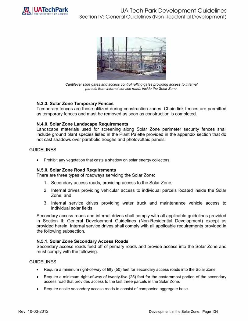
UA Tech Park Development Guidelines Section IV: General Guidelines (Non-Residential Development)
Rev: 10-03-2012 Development in the Solar Zone: Page 134
Cantilever slide gates and access control rolling gates providing access to internal
parcels from internal service roads inside the Solar Zone.
N.3.3. Solar Zone Temporary Fences Temporary fences are those utilized during construction zones. Chain link fences are permitted as temporary fences and must be removed as soon as construction is completed. N.4.0. Solar Zone Landscape Requirements Landscape materials used for screening along Solar Zone perimeter security fences shall include ground plant species listed in the Plant Palette provided in the appendix section that do not cast shadows over parabolic troughs and photovoltaic panels.
GUIDELINES
Prohibit any vegetation that casts a shadow on solar energy collectors.
N.5.0. Solar Zone Road Requirements There are three types of roadways servicing the Solar Zone:
1. Secondary access roads, providing access to the Solar Zone;
2. Internal drives providing vehicular access to individual parcels located inside the Solar Zone; and
3. Internal service drives providing water truck and maintenance vehicle access to individual solar fields.
Secondary access roads and internal drives shall comply with all applicable guidelines provided in Section II: General Development Guidelines (Non-Residential Development) except as provided herein. Internal service drives shall comply with all applicable requirements provided in the following subsection.
N.5.1. Solar Zone Secondary Access Roads Secondary access roads feed off of primary roads and provide access into the Solar Zone and must comply with the following.
GUIDELINES
Require a minimum right-of-way of fifty (50) feet for secondary access roads into the Solar Zone.
Require a minimum right-of-way of twenty-five (25) feet for the easternmost portion of the secondary access road that provides access to the last three parcels in the Solar Zone.
Require onsite secondary access roads to consist of compacted aggregate base.

UA Tech Park Development Guidelines Section IV: General Guidelines (Non-Residential Development)
Rev: 10-03-2012 Development in the Solar Zone: Page 135
N.5.2. Solar Zone Internal Service Road Requirements Internal service roads provide water truck and maintenance vehicle access to solar field parcels within the Solar Zone for service. Comply with all applicable guidelines and standards for internal service roads.
GUIDELINES Require a minimum right-of-way of twelve (12) feet for one (1) lane (two-way) internal service roads to
provide water truck and maintenance vehicle access to individual solar parcels, provided that such road loops in a manner that does not impede ingress and egress of service vehicles.
Provide a minimum ten (10) feet setback measured from the edge of the solar panel or trough to the road right-of-way or drainage channel.
Require internal service roads to be gravel roads or dirt roads provided that such dirt roads have a compacted aggregate base or a compacted stabilized aggregate base to provide a mechanism for dust control.
N.6.0. Signage Signage within the Solar Zone shall comply with all applicable guidelines provided in Section II: General Development Guidelines (Non-Residential Development) except as provided herein.
GUIDELINES Permit signs on interior gates provided that they do not exceed 24” x 48” in size and consist of
painted metal material.
N.7.0. Compatibility with Existing and Planned Uses Compatibility with adjacent existing land uses and those uses that can be reasonably anticipated based on the UA Tech Park Land Use map is required. Any solar field within the Solar Zone must comply with the following guidelines.
GUIDELINES
Mitigate all visual impacts to the adjacent Julian Wash Linear Park corridor and the Pantano trail through the provision of appropriate fencing and landscape buffers designed to enhance the trail system user experience while allowing visual continuity throughout these trails.
Provide opportunities for learning about solar energy production through the provision of interpretive nodes along the Julian Wash Linear Park that include solar panels.
Require that the Pantano trail provides seamless connectivity to the Solar Garden.
Protect the public health, safety and welfare and the value and integrity of natural and cultural resources by conforming to all other applicable standards.
N.8.0. Safety and Security Safety practices generally accepted by the solar energy industry shall be used at all times during facility construction and operation. The following guidelines apply.
GUIDELINES All land within twenty-five (25) feet of any tank or other structure containing flammable or combustible
materials shall be kept free of dry weeds, vegetation, rubbish, trash or any other flammable materials that can cause a fire.
All solar fields must be appropriately fenced in accordance to the fencing requirements provided in this chapter.
UA Tech Park Development Guidelines Section IV: General Guidelines (Non-Residential Development)
Rev: 10-03-2012 Development in the Solar Zone: Page 136
The exhausts from all engines, motors, coolers and other mechanized equipment must be vented in a direction away from the closest existing building units.
Effective management and maintenance measures must be employed to prevent any release of hazardous materials to the environment.
All solar energy facilities must comply with all applicable federal and state safety practices.
All solar energy facilities must comply with all applicable state water quality standards.
Full disclosure, including Material Safety Data Sheets, of all hazardous materials that will be transported on any public or private roadway for the solar energy facility must be provided to the Director of Facilities and Construction.
The applicant of a solar energy facility must submit an emergency preparedness and response plan that lists the potential emergencies that may be associated with the operation of the facility and include a fire prevention, response and safety plan.
N.9.0. Dust Control During construction, operators must comply with Pima County Department of Environmental Quality permit relating to dust. Operators employ practices for dust control that may include, but are not limited to, speed restrictions and regular road maintenance.
GUIDELINES
Use all available and practical methods which are technologically and economically feasible to minimize fugitive dust emissions.
N.10.0. Potential Waters of the United States Subject to the Clean Water Act Operators of solar generation facilities are responsible for identifying Potential Waters of the United States subject to the Clean Water Act and Army Corps of Engineers jurisdictional authority during the design stages of a solar generation facility as part of the UA Office of University Research Parks Design Review Process.
GUIDELINES Prevent discharge of fill materials into potential Waters of the U.S. that would require authorization
under a Clean Water Act Section 404 permit.
N.11.0. Drainage Any modification of the site drainage system requires development approval. N.12.0. Floodplains Development within the Solar Zone must be located outside any floodplain delineated by Pima County Flood Control District unless a Letter of Map Revision (LOMAR) has been issued by the Federal Emergency Management Agency (FEMA) indicating a change in floodplain delineation.
N.13.0. Archaeological and Cultural Resources Solar energy facilities or solar fields shall not cause significant degradation of cultural resources or significant disturbance of archaeological sites.
UA Tech Park Development Guidelines Section V: Residential Development Guidelines
Rev:10-03-2012 A. Land Use and Site Planning: Page 137
Section III: Residential Development Guidelines
Guidelines in this section exclude manufactured housing and apply to all types of residential development including multi-family as well as attached and detached single-family, with densities up to zero-lot lines.
A. Land Use and Site Design This chapter includes general guidelines for site planning, open space, pedestrian networks and alternative transportation modes, vehicular circulation and parking for residential development. A.1.0 – Site Planning Develop flexible and innovative designs for residential areas that promote a place-making sense of place, neighborhood interaction, and provide pedestrian and bicycle linkages to open space, golf club, golf clubhouse, Science Park Drive Multi-Use Path, recreation facilities, retail/commercial services, employment, and other uses serving residential areas within the UA Tech Park.
GUIDELINES
Provide reasonable walking times and distances to Research Park and office uses, recreation facilities, open space, social activities, and commercial services within the UA Tech Park and develop site and circulation plans with these pedestrian destinations in mind.
Develop a compact plan with strategically placed open space to accommodate visual, pedestrian, and bicycle routes throughout residential development.
Develop site layouts for residential subdivisions that protect views, encourage walkways, bikeways, and trail connectivity.
Provide trail connectivity between residential areas and golf club house. Design site plans to minimize disturbance to the natural environment and reduce infrastructure costs as follows:
GUIDELINES Minimize wash crossings. Utilize efficient and compact cluster patterns on flatter areas of the site to reduce erosion and protect
slopes and ridgelines. Maximize use of disturbed land for roads, infrastructure, and structures.
Protect views of mountain peaks and other scenic resources as follows:
GUIDELINES Provide view corridors through new residential development from adjacent residences or mitigate
negative impact on views. Orient buildings to minimize visual barriers. Vary roof lines to preserve mountain peak views to the extent practicable.
Preserve environmentally sensitive areas and culturally significant sites through innovative site design, thus providing an amenity to the new development while reinforcing the overall natural and cultural resources as follows:

UA Tech Park Development Guidelines Section V: Residential Development Guidelines
Rev:10-03-2012 A. Land Use and Site Planning: Page 138
GUIDELINES Assess vegetated areas and archaeological sites before preparing a site layout. Cluster residential development to preserve slopes, ridges, wild habitat corridors, archaeological
sites, and natural drainageways. Locate structures on previously disturbed areas. Employ zero-lot line residential development where appropriate. Use functional open space to buffer natural areas from built areas.
Encourage safer multi-family apartment or condominium residential development by adhering to the following “Safe by Design” principles when developing these types of residential development:
GUIDELINES Locate building entryways so that they are visible from other buildings, apartments, and houses. Design entryways to provide residents with a view from their home into the corridor that serves them. Provide a well-lighted pedestrian circulation system with convenient access to the UA Tech Park and
regional walkway, sidewalk, bikeway and natural trail systems. Provide lighting at doorways, windows, entryways, and in corridors and service alleys. Provide each residential unit with an area of responsibility that extends beyond the entryway. Design common stairways to serve a limited number of units. Utilize amenities and distinctive elements that extend the private space of individual apartments onto
landings and into corridors. Disperse project amenities between certain units or clusters of units, and signpost them. Create visual boundaries by a change of level, material, texture, and color. Provide landscaped or natural buffers between different land uses.
A.2.0 – Open Space and Common Areas Locate children’s play areas and other outdoor recreation activity areas so they are easily accessed from residences and other open space.
GUIDELINES
Locate children’s play areas and other outdoor recreation activity areas so that they are visible and accessible from a maximum number of homes and locations.
Provide connectivity to other open space within and outside the residential development area.
Locate community buildings such as management offices, laundry facilities, recreation centers, and community facilities within designated common areas, provided that such buildings and/or structures are no less than twenty-five (25) feet from the perimeter property lines; and no less than twenty-five (25) feet from any residential lot line.
Locate community structures such as swimming pools, except for signs, boundary fences, and walls, within the designated open space areas no less than fifty (50) feet from the perimeter property lines; and no less than twenty-five (25) feet from any new lot line created within a tract.
Lay out designated open space within a development area according to sound design principles providing a maximum accessibility to the residents of a development and to the satisfaction of the UA Office of University Research Parks Design Review Committee. Designated open space areas shall not be merely leftover or unusable land.

UA Tech Park Development Guidelines Section V: Residential Development Guidelines
Rev:10-03-2012 A. Land Use and Site Planning: Page 139
Diligently attempt to provide playgrounds, playfields or other active recreation facilities on up to twenty-five (25) percent of the required open space.
Whenever possible and practical, the open space designated within a development area shall be arranged so as to encompass a single land parcel or minimum number of parcels, linked by trails and bike paths, contiguous to the developed area and not separate from it by existing roads unless safe pedestrian access can be demonstrated.
Require that not more than five (5) percent of the total area designated open space be covered by impervious surfaces.
Require than not more than one-half (1/2) of any individual open space parcel be covered by impervious surfaces including buildings.
Arrange designated open space within residential development areas to maintain continuity and connectivity with other designated open space areas or similar areas on adjacent lands.
Provide pathways and bike routes available to public use to promote connectivity and to insure a continuous open space network throughout the UA Tech Park.
All areas designated open space within residential development must be shown in the development plan and require UA Office of University Research Parks Design Review Committee approval.
A.3.0 – Pedestrian Networks and Alternative Transportation Modes Provide direct connectivity to pedestrian walkways, bikeways, and trail systems within and outside residential areas as follows:
GUIDELINES
Connect new local streets and associated pedestrian walkways to existing local streets and arterials. Where cul-de-sac or loop roads cannot be avoided, extend pedestrian and bicycle routes to create
additional links and shortcuts. Avoid pedestrian, bicycle, and vehicular conflicts by providing separate paths for each transportation
mode. Maintain continuity of sidewalks across driveways and curb cuts.
A.4.0 – Vehicular Circulation and Parking Promote the most direct and economical vehicular, bicycle, and pedestrian circulation within residential development areas with multiple routes and connections to other areas of the UA Tech Park.
GUIDELINES
Limit long loop roads and cul-de-sacs to the extent practicable. Utilize grid or modified grid patterns to create direct routes to surrounding developments and UA Tech
Park land uses. Connect residential streets with existing UA Tech Park streets. Provide aesthetically pleasing traffic calming devices to promote street safety and discourage non-
local through traffic to the extent practicable. Provide adequate parking for single-family and multi-family residential development and associated uses such as child care, recreation facilities and school.

UA Tech Park Development Guidelines Section V: Residential Development Guidelines
Rev:10-03-2012 A. Land Use and Site Planning: Page 140
GUIDELINES Comply with minimum parking rates for residential development provided in the following table.
Table 8: Minimum Parking Rates for Residential Development
Land Use Rate 1
Residential Residential (Single-Family) 2 off-street spaces per residence, plus ¼ space on-street parking times the total number of units for visitor and guest parking and submit requirements for Tech Park review Residential (Multi-family) 2 covered parking spaces per multi-family residence, plus ½ space times the total number of units per guest and visitor parking and submit requirements for Tech Park approval
Child Care Facility 1 parking space per 200 sq. ft. of Gross Floor Area (GFA).
Recreation Facilities 1 parking space per 300 sq. ft. of space
School 1 parking space per 200 sq. ft. of GFA or 1 parking space per 250 sq. ft. of office area and 1 parking space per 100 sq. ft. of classroom area.
1 The required spaces may include compact, handicapped, and motorcycle spaces. 2 Driveway space is considered parking space for purposes of parking space requirements. Provide Handicapped or “Barrier Free” parking.
GUIDELINES Comply with Handicapped or “Barrier Free” parking rates provided in Section IV (E.3.5) of this
document.
UA Tech Park Development Guidelines Section V: Residential Development Guidelines
Rev: 10-03-2012 B. Community Character and Design: Page 141
B. Community Character and Design This chapter provides spatial and functional relationships for residential areas.
B.1.0 – Spatial and Functional Relationships Add visual interest and character to the streetscape and increase the overall appeal of residential areas as provided in the following guidelines.
GUIDELINES
Vary lot size, building footprint, building orientation, setbacks, orientation of garages and porches to create a sense of uniqueness.
Encourage pedestrian and bike-oriented activity in residential areas by creating a streetscape of human scale, which increases the use of walkways, sidewalks and bikeways, thereby making residential areas safer as provided in the following guidelines:
GUIDELINES De-emphasize garages and accessory buildings and orient porches, doors and windows to the street. Integrate garages and accessory buildings into the overall architectural design. Avoid prominent and repetitious placements for garages. Use side or rear garage access to the extent practicable. Use shared driveways among clustered units to the extent practicable. Include front porches to put “eyes on the street.”
Clearly identify public, semi-public, and private areas as provided in the following guidelines.
GUIDELINES Use design elements to create distinctions between different areas and to define property
owner/occupant areas by using low walls, fences, landscaping, level changes, lighting, color and changes in paving structure.
Visually harmonize non-residential or higher density residential developments with adjacent residential neighborhoods as provided in the following guidelines.
GUIDELINES Integrate architectural elements from the neighborhoods into the visual vocabulary of the
development. To the extent practicable, use similar colors, details, and finished materials as those in the adjacent
areas. Use building massing that expresses the neighborhood scale, especially along edges and
streetscapes.
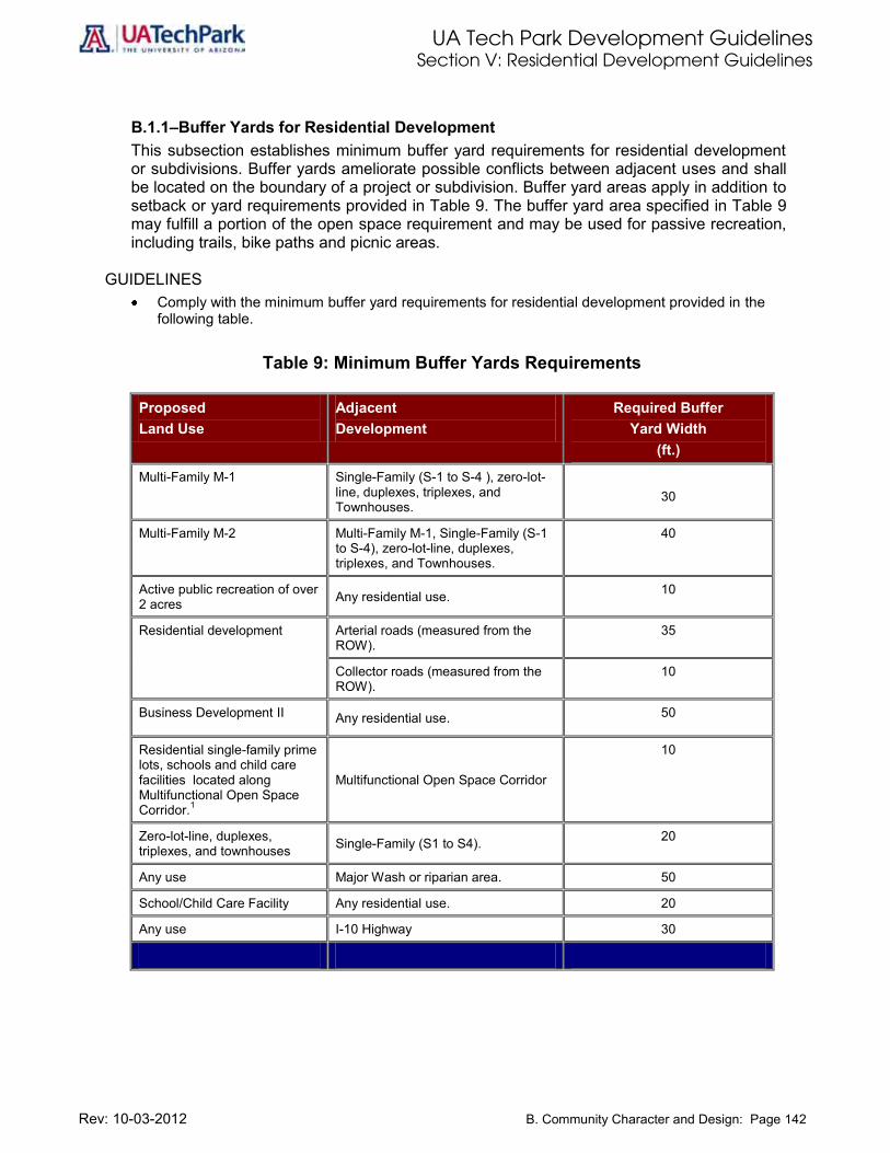
UA Tech Park Development Guidelines Section V: Residential Development Guidelines
Rev: 10-03-2012 B. Community Character and Design: Page 142
B.1.1–Buffer Yards for Residential Development This subsection establishes minimum buffer yard requirements for residential development or subdivisions. Buffer yards ameliorate possible conflicts between adjacent uses and shall be located on the boundary of a project or subdivision. Buffer yard areas apply in addition to setback or yard requirements provided in Table 9. The buffer yard area specified in Table 9 may fulfill a portion of the open space requirement and may be used for passive recreation, including trails, bike paths and picnic areas.
GUIDELINES
Comply with the minimum buffer yard requirements for residential development provided in the following table.
Table 9: Minimum Buffer Yards Requirements
Proposed Land Use
Adjacent Development
Required Buffer Yard Width
(ft.)
Multi-Family M-1 Single-Family (S-1 to S-4 ), zero-lot-line, duplexes, triplexes, and Townhouses.
30
Multi-Family M-2 Multi-Family M-1, Single-Family (S-1 to S-4), zero-lot-line, duplexes, triplexes, and Townhouses.
40
Active public recreation of over 2 acres Any residential use. 10
Residential development Arterial roads (measured from the ROW).
35
Collector roads (measured from the ROW).
10
Business Development II Any residential use. 50
Residential single-family prime lots, schools and child care facilities located along Multifunctional Open Space Corridor.1
Multifunctional Open Space Corridor
10
Zero-lot-line, duplexes, triplexes, and townhouses Single-Family (S1 to S4). 20
Any use Major Wash or riparian area. 50
School/Child Care Facility Any residential use. 20
Any use I-10 Highway 30

UA Tech Park Development Guidelines Section V: Residential Development Guidelines
Rev: 10-03-2012 B. Community Character and Design: Page 143
B.1.2– Landscaping and Fencing Requirements within Buffer Yards This subsection establishes minimum landscaping and fencing requirements within established buffer yards. Provide appropriate screening within the buffer yard to the satisfaction of the UA Office of University Research Parks Design Review Committee and in accordance with the following guidelines:
GUIDELINES
Include a planting strip, utilizing plants included in the UA Tech Park Plant List (Appendix A), at least ten (10) feet wide at or near the property line, including trees or shrubs at least two (2) feet high at planting, which may be expected to form a year-round screen within three (3) years; or
Provide a landscaped earth mound of at least four (4) feet in height; or
Include a decorative fence or wall of a minimum of five (5) feet in height, designed with durable materials, texture, and colors compatible with adjacent uses and the overall concept of the UA Tech Park.
Install public utilities and locate maintenance roads within easements or buffer yards.

UA Tech Park Development Guidelines Section V: Residential Development Guidelines
Rev: 10-03-2012 C. Minimum Standards for Single-Family Residential Development: Page 144
C. Minimum Standards for Single-Family Residential Development This chapter provides minimum standards for Single-Family residential development. C.1.0 –Setback and Building Height Requirements Residential building setbacks provide space for private yards, and building separation for fire protection/security, building maintenance, sunlight, and air circulation. At the UA Tech Park, residential development promotes human-scale design and traffic calming by downplaying the visual impact of garages along the street and encouraging the use of streetscapes, sidewalks, and pocket parks. These standards encourage placement of residences close to the street for public safety and neighborhood security. Building setbacks are measured from the primary structure wall to the respective property line. Setbacks for decks and porches are measured from the edge of the deck or porch to the property line. Setbacks provided on Table 6 apply to primary structures as well as accessory structures.
GUIDELINES
Comply with the setback and building height requirements for single-family residential development (single-family, zero-lot-line, and townhouse development) provided in Table 6.
C.1.1 – General Yard Requirements In addition to setback standards provided in this section, the following general yard requirements apply to single-family detached and attached residential development.
C.1.2 – Corner Lots and Through Lots
GUIDELINES
Corner lots and through lots shall comply with the established minimum front yard setback requirements only with respect to the principal front line, not with respect to the side yard.
C.1.3 – Front, Side and Rear Yard Depth Measurement The minimum front, side, and rear yard depth shall be measured as follows:
GUIDELINES
Perpendicular from front, rear, or side lot lines at the closest points to the wall of the proposed building or accessory structure.
When measured from an alley, one-half (1/2) of the alley width may be included as a portion of the rear or side yard.
For any project without individual lots, the side and rear yard shall be measured from the building to the parcel boundary or property line.
The minimum front, rear, and side yard widths for irregular lots shall be measured from the portion of the building or accessory structure closest to the lot line.
C.1.4 – Exceptions and Modifications to Minimum Yard Requirements Allow exceptions and modifications to minimum yard requirements by adhering to the following guidelines.

UA Tech Park Development Guidelines Section V: Residential Development Guidelines
Rev: 10-03-2012 C. Minimum Standards for Single-Family Residential Development: Page 145
GUIDELINES The following structures are allowed to project into the minimum required yard setback, provided that
such projection does not exceed the following dimensions:
a. Awnings, canopies, cornices, eaves or other architectural features approved by the UA Office of University Research Parks Design Review Committee are allowed to project a maximum of three (3) feet into the required yard setback.
b. Bay windows, balconies, chimneys, and porches are allowed to project three (3) feet into the required yard setback.
c. Open fire escapes are allowed to project five (5) feet into the required yard setback.
d. Uncovered stairs or necessary landings are allowed to project six (6) feet into the required yard setback.
e. Patios and decks (not enclosed) and attached storage sheds not exceeding one-hundred twenty (120) square feet may extend ten (10) feet into the rear yard setback.
Fences, walls and hedges may be located in required yards in accordance with the following:
a. In front yards, fences and hedges approved by the UA Office of University Research Parks Design Review Committee shall not exceed four (4) feet in height above ground elevation.
b. In rear and side yards, fences, walls and hedges approved by the UA Office of University Research Parks Design Review Committee shall not exceed six (6) feet in height above surface ground elevation.
c. All fences or walls will be constructed with the finished side facing adjacent parcels or the street.
d. Chain link fences are prohibited in residential areas.
No more that 50 % of any residential yard may be impervious surface.
C.1.5 –Accessory Uses In Residential Areas Allow accessory uses in residential areas, provided that such accessory uses comply with the following guidelines.
GUIDELINES
If the facilities are used by the occupants or guests of the principal use and no admission or membership fees are charged, locate the edge of recreation facilities, such as swimming pools and tennis courts, not less than ten (10) feet from any side or rear lot line.
Install a safety fence with self-closing gate at least four (4) feet in height around pool areas.
Provide a walkway at least three (3) feet wide around pool wall and safety fence.

UA Tech Park Development Guidelines Section V: Residential Development Guidelines
Rev: 10-03-2012 C. Minimum Standards for Single-Family Residential Development: Page 146
Table 10: Minimum Standards for Single-Family Residential Development
Type of Residential Development Options
Maximum Density
(units/acre)
Minimum Front Yard
(ft.)
Minimum Rear Yard
(ft.) 2
Minimum Side Yard
(ft.)3
Maximum Building Height
Single-Family (S-1) 5 10 10 5 2 stories
Single-Family (S-2) 6 10 10 5 2 stories
Single-Family (S-3) 8 10 10 3 2 stories
Single-Family (S-4) 12 10 10 3 2 stories
Zero-lot-line 1 8 20/5 10/10 3 2 stories
Zero-lot-line 1 10 20/5 10/10 3 2 stories
Townhouse Units 15 N/A4 10 105 2 stories
Notes: 1 Zero-lot-line (single-family courtyard home) development is subject to the same standards as single-family development, except that a side yard setback is not required
on one side of a typical lot. This type of residential unit allows development on smaller (i.e., narrower) lots and still provide usable outdoor living area in side-oriented courtyards. See Standards for Zero-lot-line Residential Development in Chapter D of this volume. The following setback requirements apply to zero-lot-line residential development:
o A minimum front yard setback of five (5) feet and a minimum rear yard setback of ten (10) feet are required for rear-loaded garage houses.
o A minimum front yard setback of twenty (20) feet and a minimum rear yard setback of ten (10) feet are required for front-loaded garage houses. 2 Prime lots located along Science Park Drive must provide a continuous buffer yard of 15 feet from the property line to Science Park Drive Right-of-Way (see Buffer
Yard Section). 3 Minimum side yard on each side of the principal building. When zero-lot-line development is permitted, the minimum side yard setback shall be 6 feet on one side of
the dwelling units, and no setback required on the opposite side. (See standards for zero-lot-line residential development) 4 See Chapter: E. Single-Family Attached (Townhouse) Residential Development. 5 Side yard required for end units only. 6 Innovative deviations from these minimum standards that prove to deliver high-quality products will be considered by the UA Office of University Research Parks
Design Review Committee.

UA Tech Park Development Guidelines Section V: Residential Development Guidelines
Rev: 10-03-2012 D. Zero-Lot-Line Residential Development: Page 147
D. Zero-lot-line Residential Development This chapter provides development guidelines for zero-lot-line residential development. Guidelines within this chapter only apply to zero-lot-line development. D.1.0. – Zero-lot-line Residential Development The zero-lot-line residential development provisions are designed to provide more affordable housing opportunities for a wide range of UA Tech Park users and to promote a more efficient utilization of land while assuring compatibility with, and maintaining the stability and quality of the UA Tech Park.
D.1.1 –Setback and Building Height Requirements Comply with the setback and building heights requirements for zero-lot-line residential development provided in Table 10.
GUIDELINES
Limit site coverage of zero-lot-line residential development to tracts of at least three (3) acres unless otherwise approved by the UA Office of University Research Parks Design Review Committee.
Existing overhang or covered walkway, a special covering, weatherproof outdoor bicycle lockers, or indoor storage areas are forms of covered bicycle parking.
Open decks or porches may project into the larger side yard provided a minimum of three (3) feet from the edge of the deck or porch to the closest property line is maintained.
Solid walls around decks or porches projecting into the side yard are prohibited.
Garages or structures for the storage of automobiles are prohibited in lots less than forty-seven (47) feet in width in zero-lot-line residential development, except when located in the rear of the property and serviced by a rear alley.
D.1.2 – Additional Requirements
GUIDELINES
Configuration of streets, sidewalks, locations of public improvements, open space and recreational areas for zero-lot-line residential development require UA Office of University Research Parks Design Review Committee approval.
D.1.3 – Parking
GUIDELINES
Provide off-street parking at the same ratio provided for single-family development.
Prohibit parking of recreational vehicles, motor homes, or towed trailers within the required front setback area.
Provide access to garage or carport through the rear in lots less than forty-seven (47) feet in width.

UA Tech Park Development Guidelines Section V: Residential Development Guidelines
Rev: 10-03-2012 E. Single-Family Attached (Townhouse) Residential Development: Page 148
E. Single-Family Attached (Townhouse) Residential Development Townhouses are individual dwelling units sharing at least one common wall and attached to one or more dwelling units. Each townhouse occupies space from the ground to the roof and has direct access to private open space. No portion of a unit may occupy space above or below another unit, with the exception of townhouse units constructed over a common shared parking garage. This chapter provides development guidelines for single-family attached (townhouse) residential development. Guidelines within this chapter only apply to single-family attached (townhouse) residential development. E.1.0 – Building Design Provide building façade modulation on facades exceeding 60 feet and facing abutting streets or lower density residential development as indicated in the following guidelines.
GUIDELINES Provide a maximum wall length without modulation of 30 feet.
Limit the sum of the modulation depth and the modulation width to a minimum of eight (8) feet.
Neither the modulation depth nor the modulation width shall be less than two (2) feet.
Allow any other technique approved by the UA Office of University Research Parks Design Review Committee that achieves the intent of this section.
Design rear and sides of buildings with attention to architectural character and detail comparable to the front façade, particularly if rear and sides of buildings are visible from streets or adjacent property.
E.1.1 – Dwelling Unit Vehicular Access and Parking Location Provide appropriate vehicular access and parking locations for townhouse developments by adhering to the following guidelines.
GUIDELINES Place parking areas to the rear of building with primary vehicular access via the alley on sites abutting
an alley constructed to a width of at least twenty (20) feet, unless otherwise approved by the UA Office of University Research Parks Design Review Committee due to physical site limitations.
When alley access is provided, no additional driveway access from the public street is allowed except as necessary to access parking under the structure or for fire protection.
When the number of uncovered common parking spaces for attached dwelling residences exceeds 30 parking spaces, no more than fifty (50) percent of these uncovered parking spaces shall be permitted between the street property line and any building, unless approved by UA Office of University Research Parks Design Review Committee due to physical site limitations.
E.1.2 – Roofline Treatments Create an attractive, well-proportioned development by adhering to the following guidelines.
GUIDELINES
Provide attractive roofs and parapet lines.
Include parapets to conceal rooftop equipment, chimneys, and solar panels.
Minimize mechanical equipment on rooftops to reduce negative visual impacts and to reduce energy costs.

UA Tech Park Development Guidelines Section V: Residential Development Guidelines
Rev: 10-03-2012 E. Single-Family Attached (Townhouse) Residential Development: Page 149
Integrate solar energy techniques and other mechanical equipment into the overall design of the building and screen all mechanical equipment on roofs.
Ensure that roof features and parapets complement the character of adjacent lower density neighborhoods while maintaining the overall character of the UA Tech Park.
Encourage a high quality and visually interesting roof ‘horizon’.
Provide a variety of roof lines and plane lines.
Vary roof lines to reduce the apparent scale.
Use three-dimensional cornice treatments, parapet wall details, overhanging eaves, etc. to enhance the architectural character of the roof.
E.1.3 – Standards for Single-Family Attached (Townhouse) Residential Development Allow the development of single-family attached townhouse residential development in areas designated Residential in the UA Tech Park Land Use Plan, provided that such development complies with the following guidelines.
GUIDELINES
Require a minimum site area of twenty-thousand (20,000) square feet for townhouse development.
Limit the number and width of consecutively attached townhouses to 8 units, or 160 feet, whichever is less;
Limit each townhouse building block to no less than three (3) and no more than eight (8) dwelling units.
Require a minimum twenty (20) feet front yard, measured from the building wall to the property line, for each individual townhouse unit. Lot width for end units are required to provide front and side yards.
Provide required off-street parking on the rear of the lot or within 100 feet of the lot.
Preserve a minimum of 25 percent of the gross land area as natural or landscaped open space or recreational area.
E.1.4 – Street Access for Single-Family Attached (Townhouse) Residential Development Townhouse, duplex, and triplex developments receiving direct access from a public or private street shall comply with all the standards and guidelines provided in this section in order to minimize interruption of adjacent sidewalks by driveway entrances and slow traffic, improve appearance of the street, and minimize paved surfaces for better storm water management.
GUIDELINES
Townhouses, duplex and triplex subdivisions (4 or more lots) shall receive vehicle access only from the rear alley.
Access alleys require UA Office of University Research Parks Design Review Committee approval.
Alleys are not required when existing development pattern or topography makes construction of an alley impracticable at the discretion of the UA Office of University Research Parks Design Review Committee.
As necessary, the UA Office of University Research Parks Design Review Committee may require dedication of right-of-way easements and construction of pathways between townhouse lots (e.g., between building breaks).

UA Tech Park Development Guidelines Section V: Residential Development Guidelines
Rev: 10-03-2012 E. Single-Family Attached (Townhouse) Residential Development: Page 150
When garages face the street, they shall be recessed behind the front elevation (i.e., living areas or covered porch) by a minimum of 4 feet.
The maximum allowed driveway width facing the street is 24 feet per dwelling unit. The maximum combined garage width per unit is 50 percent of the total building width. For example, a 24-foot wide unit may have one 12-foot wide recessed garage facing the street.
Two adjacent garages shall share one drive when individual driveways would otherwise be separate by less than 20 feet (i.e. the width of one on-street parking space).
When a driveway serves more than one lot, the developer shall record an access maintenance easement/agreement to benefit each lot, prior to UA Tech Park building permit issuance.
E.1.5 – Common Areas for Single-Family Attached (Townhouse) Residential Development “Common areas” such as landscaping in private tracts, shared driveways, private alleys, and similar uses shall be maintained by a homeowners association or other legal entity approved by the UA Tech Park and adhere to the following guidelines:
GUIDELINES
A homeowners association is responsible for exterior building and yard maintenance. A copy of any applicable covenants, restrictions and conditions shall be provided to the UA Office of
University Research Parks Design Review Committee prior to development approval.

UA Tech Park Development Guidelines Section V: Residential Development Guidelines
Rev: 10-03-2012 F. Minimum Standards for Multi-Family Residential Development: Page 151
F. Minimum Standards for Multi-Family Residential Development Design and development guidelines included in this chapter promote high quality multi-family development within the UA Tech Park. Guidelines provided in this chapter include multi-family developments in general and the following specific types of multi-family uses: (1) Apartments; and (2) Condominium Units. This chapter provides development guidelines for multi-family residential development. Guidelines within this chapter only apply to multi-family residential development. F.1.0 – Site Coverage
GUIDELINES Comply with site coverage requirements for multi-family residential development provided in Table
10.
F.1. 1 – Pedestrian Entries Provide pedestrian entries that are visible from the street by adhering to the following guidelines.
GUIDELINES
Provide clear pedestrian entries to buildings from both the streets and the parking lots.
Enhance building entries that are not on the street by providing clear paths using building and landscaping elements.
F.1. 2 – Minimize Impact to Adjacent Sites Locate buildings as to minimize disruption of privacy and impact of outdoor activities of residents in adjacent lower density residential uses by adhering to the following guidelines.
GUIDELINES Reduce the number of windows and decks overlooking adjacent houses or yards.
Avoid the view from upper stories of new buildings into adjacent houses or yards.
Step back the upper floors or increase the side or rear setback so that window areas are farther from the property line.
Minimize windows with views of living spaces that might infringe on the privacy of adjacent residents.
Stagger windows so they do not align with adjacent windows.
F.1. 3 – Open Space Site multi-family developments to maximize opportunities for creating usable, attractive, and well-integrated open spaces as provided in the following guidelines.
GUIDELINES
Provide safe and efficient access to open space for recreation and social activities.
Design and orient open space areas to take advantage of available sunlight.
Shelter open space areas from wind, noise, and traffic of adjacent streets.
Provide conveniently accessible common areas such as courtyards.

UA Tech Park Development Guidelines Section V: Residential Development Guidelines
Rev: 10-03-2012 F. Minimum Standards for Multi-Family Residential Development: Page 152
Private open spaces, when provided, should be contiguous with the units they serve, with direct access from the unit, and adequate screening from public view.
Locate and design decks, balconies and upper level terraces so that they minimize the impact on adjacent residential areas.
Provide minimum common open space for M-1 and M-2 multi-family development at the rates shown in Table 11.
Provide minimum private open space per dwelling unit for M-1 and M-2 multi-family development at the rates shown in Table 11.
F.1. 4 – Landscaping Include plant material, special pavement, trellises, screen walls, planters, site furniture and similar features in the landscape design to enhance the development.
GUIDELINES
Landscape all areas not covered by structures, drives, parking lots, or other hardscape features.
Include special features such as courtyards, gardens, or pools in the design.
Screen buildings from view by its neighbors and from higher density UA Tech Park land uses.
Provide a variety of plants, including trees, tall shrubs, grass, and groundcover. Trees can be used to provide shading and climatic cooling for nearby units.
Screen parking lots and ensure that each section of ten (10) parking spaces is separated from additional spaces by a landscaped peninsula.
Incorporate annuals into landscape treatments to provide year-round screening.
F.1. 5 – Parking and Vehicle Access Minimize the impact of parking and driveways on pedestrian systems, adjacent properties, and pedestrian safety by adhering to the following guidelines:
GUIDELINES
Disperse surface parking in smaller parking courts located in the side or rear yards, away from primary pedestrian walkways.
Break large parking lots into smaller ones.
Minimize the number of driveways and curb cuts.
Share driveways with adjacent multi-family development, when feasible.
Locate parking in less visible areas of the site.
Locate driveways so they are visually less dominant.
Separate parking courts from each other with dwelling units or with landscaped buffers.
Provide walkways from units to parking areas.
F.1. 6 – Controlling Parking Quantity GUIDELINES
Provide sufficient on-site parking to meet resident needs and prevent spillover parking impacts at the rates provided in Table 4 of this document.
UA Tech Park Development Guidelines Section V: Residential Development Guidelines
Rev: 10-03-2012 F. Minimum Standards for Multi-Family Residential Development: Page 153
F.1. 7 – Building Articulation Avoid long, unbroken facades and box-like forms by adhering to the following guidelines.
GUIDELINES
Break up building facades to give the appearance of a collection of smaller structures.
To the extent possible, each unit should be individually recognizable. This can be accomplished with the use of balconies, setbacks, projections, and by the pattern and rhythm of windows and doors.
Secondary hipped or gabled roofs covering the entire mass of a building are preferable to mansard roofs or segments of a pitched roof applied at the structure’s edge.
F.1. 8 – Architectural Style Build high quality residential environments and utilize architectural styles that are compatible with the development concept of the UA Tech Park by adhering to the following guidelines.
GUIDELINES
Design multi-family developments that are compatible with surrounding uses.
Ensure that the height, bulk, and scale of high density residential areas do not adversely impact adjacent single-family areas
F.1. 9 – Height, Bulk, and Scale Minimize the impact of multi-family development and achieve an acceptable level of compatibility with the scale of development anticipated in the UA Tech Park Land Use Plan by adhering to the following guidelines.
GUIDELINES
Articulate building facades vertically and horizontally in intervals that harmonize with existing structures or platting patterns.
Increase building setback at the ground level.
Reduce the bulk of upper floors.
Limit the length of building facades.
F.1. 10 – Materials Select durable and high quality materials for multi-family buildings by adhering to the following guidelines.
UA Tech Park Development Guidelines Section V: Residential Development Guidelines
Rev: 10-03-2012 F. Minimum Standards for Multi-Family Residential Development: Page 154
GUIDELINES
Utilize building materials that conform to development standards of the UA Tech Park.
Prohibit smooth face concrete panels or blocks and aluminum and vinyl siding.
F.1. 11 – Mechanical and Utility Equipment Provide appropriate screening for mechanical and utility equipment as follows:
GUIDELINES
All mechanical and utility meters, whether mounted on the roof or ground must be screened from view at the public right-of-way.
All screening devises are to be compatible with the architecture and color of adjacent buildings.
F.2.0 – Apartment and Condominium Apartment and condominium style multi-family developments are defined as those in which two or more dwelling units are attached. Typically these high-end multistory dwelling units are accessed through shared interior entrances and provide a diversity of amenities. F.2.1 – Building Design Design apartment style development as to express a compatible character that complements the architectural style and siting patterns of adjacent development within the UA Tech Park.
F.2.2 – Entry Areas Provide appropriate gateways to apartment style development by adhering to the following guidelines:
GUIDELINES
Design entry areas to the development that help orient visitors and residents alike.
Include amenities such as landscaping, recreational facilities, club house, public art, fountains and directories for the development in proximity to main gateways.
F.2.3 – Dwelling Unit Access
GUIDELINES Provide primary access to units through an internal hallway or through a direct staircase to above
ground apartment unit doorways.
Avoid the use of long, monotonous access balconies and corridors providing access to units.
F.2.4 – Site Planning Apartment style developments tend to generate larger buildings and parking areas and reduce private open space. If not adequately designed, parking facilities can dominate the site. Open spaces may be relegated to leftover areas that do not relate well to the principal structure. Provide appropriate site planning for apartment style development by adhering to the following guidelines:

UA Tech Park Development Guidelines Section V: Residential Development Guidelines
Rev: 10-03-2012 F. Minimum Standards for Multi-Family Residential Development: Page 155
GUIDELINES
Require that the site plans for apartment villages identify location of buildings, club house, amenities, open space, landscape areas, and parking lots at the Design Review stage.
Avoid residential development surrounded by high walls, parking lots, and rows of carports along public streets.
F.2.5 – Low Rise Appearance Unless otherwise approved by the UA Office of University Research Parks Design Review Committee, encourage apartment villages to maintain a low-rise appearance by adhering to the following guidelines.
GUIDELINES
Limit development to three or four stories.
Utilize setback, lot coverage, and floor area ratio requirements as additional tools to regulate density appearance.
F.2.6 – Pedestrian Access from Parking Areas Provide convenient pedestrian access to building entrances from parking areas as follows.
GUIDELINES Align landscaping islands, wherever possible, with major building entrances to provide pedestrian
access to building entrances from parking areas.
Parking bulbs aligning with entrances should be at least two spaces wide and include a pathway and a vertical landscape or architectural element, such as a trellis.
Provide one half (1/2) visitor parking space per dwelling unit (off-street) located within six hundred (600) feet of the dwelling unit.
F.2.7 – Accessory Structures
GUIDELINES
Design accessory buildings such as laundry facilities, recreation buildings and sale/lease offices so they are consistent and complementary in architectural style, materials, and color palettes.
For permitted accessory uses and structures see Section V: Master Plan Implementation (F.2.7.1) in the UA Tech Park Master Plan
F.2.8. - Private Open Space Standards for Multi-Family Development Private open space areas are required for ground-floor and upper-floor housing units based on the following guidelines.
GUIDELINES
All ground-floor housing units shall have front or rear patios or decks measuring at least 48 square feet (ground-floor housing unit means housing units within 5 feet of the finished grade).
All upper-floor housing units shall have balconies or porches measuring at least 24 square feet (upper-floor housing means housing units which are more than 5 feet above the finished grade).

UA Tech Park Development Guidelines Section V: Residential Development Guidelines
Rev: 10-03-2012 F. Minimum Standards for Multi-Family Residential Development: Page 156
Table 11: Minimum Standards for Multi-Family Residential Development
Type of Residential Development
Minimum Lot
Coverage
Maximum Permitted Density 1
Minimum Common
Open Space 2
Minimum Lot Area (sq. ft.)
Buffer Yard (ft.)
Minimum Private
Open Space (sq. ft.) 3
Minimum Side Yard Between
Buildings (ft.)
Maximum Building Height
Multi-Family M-1 50% 20 25% 43,560 20 100 15 2 stories
Multi-Family M-2 50% 35 25% 5 acres 30 100 15 3 stories
Notes: 1 M-1 and M-2 multi-family development require UA Office of University Research Parks Design Review Committee approval for location. For M-1
development, parcels of five acres or larger may be at a maximum density of twenty-five (25) dwelling units per acre. For M-2 development, parcels of five acres or larger may be developed at a maximum density of thirty-five (35) dwelling units per acre.
2 Minimum common open space excludes parking and driveway areas. 3 Minimum private open space per dwelling unit, either patio or balcony, or combination thereof. 4 Apartment buildings higher than 3 stories may be permitted in areas adjacent to the Regional Commercial land use, with previous approval of the UA
Office of University Research Parks Design Review Committee. 5 Innovative deviations from these minimum standards that prove to deliver high-quality products will be considered by the UA Office of University
Research Parks Design Review Committee.

UA Tech Park Development Guidelines Section V: Residential Development Guidelines
Rev: 10-03-2012 F. Minimum Standards for Multi-Family Residential Development: Page 157
Table 12: Supplemental Standards for Multi-Family Residential Development
Type of Residential Development
Building Mass
Common Open Space Area1
Trash Receptacles
Multi-Family M-1 and M-2
The Maximum width or length of a multiple family building shall not exceed 160 feet (from end-wall to end-wall)
Inclusive of required setback yards or perimeter setbacks, a minimum of 20 percent of the site area shall be designated and permanently reserved as usable common open space.
Trash receptacles shall be oriented toward common open space areas and away from adjacent single-family residences and shall be screened with a hedge or solid fence or wall of not less than 6 feet in height.
Notes: 1 The site area is defined as the lot or parcel on which the development is planned, after subtracting any required dedication of street
right-of-way and other land for public purposes (e.g., public park or school grounds, etc.).
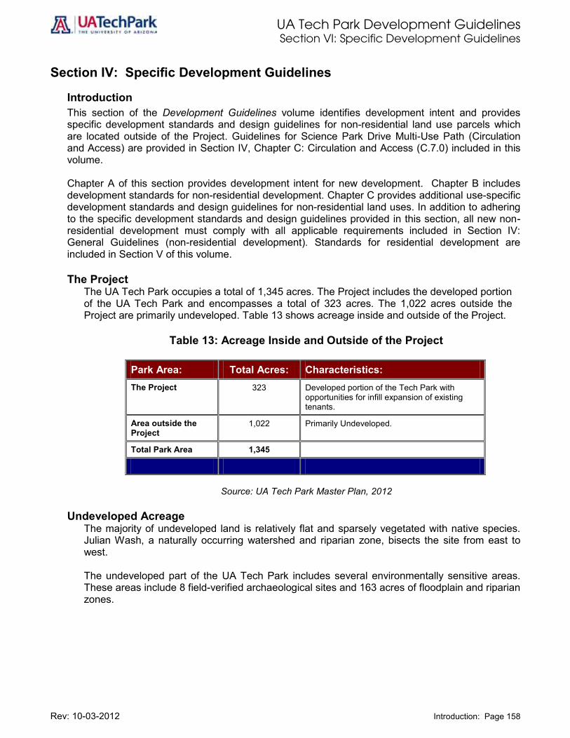
UA Tech Park Development Guidelines Section VI: Specific Development Guidelines
Rev: 10-03-2012 Introduction: Page 158
Section IV: Specific Development Guidelines
Introduction This section of the Development Guidelines volume identifies development intent and provides specific development standards and design guidelines for non-residential land use parcels which are located outside of the Project. Guidelines for Science Park Drive Multi-Use Path (Circulation and Access) are provided in Section IV, Chapter C: Circulation and Access (C.7.0) included in this volume. Chapter A of this section provides development intent for new development. Chapter B includes development standards for non-residential development. Chapter C provides additional use-specific development standards and design guidelines for non-residential land uses. In addition to adhering to the specific development standards and design guidelines provided in this section, all new non-residential development must comply with all applicable requirements included in Section IV: General Guidelines (non-residential development). Standards for residential development are included in Section V of this volume. The Project
The UA Tech Park occupies a total of 1,345 acres. The Project includes the developed portion of the UA Tech Park and encompasses a total of 323 acres. The 1,022 acres outside the Project are primarily undeveloped. Table 13 shows acreage inside and outside of the Project.
Table 13: Acreage Inside and Outside of the Project
Park Area: Total Acres: Characteristics: The Project 323 Developed portion of the Tech Park with
opportunities for infill expansion of existing tenants.
Area outside the Project
1,022 Primarily Undeveloped.
Total Park Area 1,345
Source: UA Tech Park Master Plan, 2012
Undeveloped Acreage
The majority of undeveloped land is relatively flat and sparsely vegetated with native species. Julian Wash, a naturally occurring watershed and riparian zone, bisects the site from east to west.
The undeveloped part of the UA Tech Park includes several environmentally sensitive areas. These areas include 8 field-verified archaeological sites and 163 acres of floodplain and riparian zones.
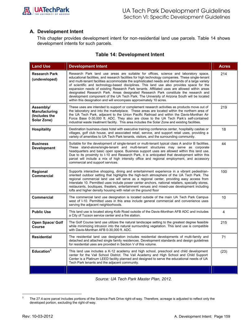
UA Tech Park Development Guidelines Section VI: Specific Development Guidelines
Rev: 10-03-2012 A. Development Intent: Page 159
A. Development Intent This chapter provides development intent for non-residential land use parcels. Table 14 shows development intents for such parcels.
Table 14: Development Intent
Land Use Development Intent Acres
Research Park (undeveloped)
Research Park land use areas are suitable for offices, science and laboratory space, educational facilities, and research facilities for high technology companies. These single-tenant and multi-tenant facilities accommodate the sophisticated needs and demands of a large variety of scientific and technology-based disciplines. This land use also provides space for the expansion needs of existing Research Park tenants. Affiliated uses are allowed within areas designated Research Park. Areas designated Research Park constitute the research and development component of the UA Tech Park. The University of Arizona South will be located within this designation and will encompass approximately 10 acres.
214
Assembly/ Manufacturing (Includes the Solar Zone)
These uses are intended to support or complement research activities as products move out of the laboratory and into the marketplace. These areas are located within the northern area of the UA Tech Park, adjacent to the Union Pacific Railroad and within the Davis-Monthan Air Force Base 0-30,000 ft. ADC. They also are close to the UA Tech Park’s self-contained industrial waste treatment facility. This area includes the Solar Zone and existing facilities.
219
Hospitality Destination business-class hotel with executive training conference center, hospitality casitas or villages, golf club house, and associated retail, service, and support retail uses, providing a variety of amenities to UA Tech Park tenants, visitors, and the surrounding community.
18
Business Development
Suitable for the development of single-tenant or multi-tenant typical class A and/or B facilities. These stand-alone/single-tenant and multi-tenant structures may serve as corporate headquarters and basic open space. Business support uses are allowed within this land use. Due to its proximity to I-10 and Research Park, it is anticipated that development within this parcel will include a mix of high intensity office and regional employment, and accessory commercial and support services.
44
Regional Commercial
Supports interactive shopping, dining and entertainment experience in a vibrant pedestrian-oriented outdoor setting that highlights the high-tech atmosphere of the UA Tech Park. The regional commercial land use will serve as a regional center, providing easy access from Interstate 10. Permitted uses include power center anchors, national retailers, specialty stores, restaurants, boutiques, theaters, entertainment venues and mixed-use development including lofts and higher density housing with retail on the ground floor
100
Commercial The commercial land use designation is located outside of the main UA Tech Park Campus west of I-10. Permitted uses in this area include general commercial and convenience uses serving the adjacent neighborhoods.
10
Public Use This land use is located along Kolb Road outside of the Davis-Monthan AFB ADC and includes a City of Tucson service center and a fire station.
4
Open Space/ Golf Course
The Golf Course land use utilizes the natural landscape setting to the greatest degree feasible while minimizing intrusion into the natural surrounding vegetation. This land use is compatible with Davis-Monthan AFB 0-30,000 ft. ADC.
215
Residential The residential land use designation includes residential developments of multi-family and detached and attached single family residences. Development standards and design guidelines for residential uses are provided in Section V of this volume.
71
Education3 This land use includes a K-12 academy and high school, preschool and child development center for the Vail School District. The Vail Academy and High School and Child Support Center is a Platinum LEED facility planned and designed to serve the educational needs of UA Tech Park tenants and the adjacent community.
(23)
Source: UA Tech Park Master Plan, 2012.
3 The 27.4-acre parcel includes portions of the Science Park Drive right-of-way. Therefore, acreage is adjusted to reflect only the
developed portion, excluding the right-of-way.

UA Tech Park Development Guidelines Section VI: Specific Development Guidelines
Rev: 10-03-2012 A. Development Intent: Page 160
Table 14: Development Intent (Continued)
Land Use Development Intent Acres
Park and Ride This regional park and ride facility is located on the northwest corner of the UA Tech Park along Kolb Road. It provides access to the UA Tech Park Shuttle service and access to trail heads, nature trails, hiking trails, and bicycle paths, providing connectivity to the UA Tech Park Trail System and the regional Julian Wash trail system.
12
Davis-Monthan Air Force Base Dedicated Open Space Corridor
In addition to the 25% minimum open space required at parcel level, the UA Tech Park designates 138 acres as the Davis-Monthan AFB Dedicated Open Space Corridor. Of the total 138 acres, 112 are located outside of the Project Area. This corridor supports Davis-Monthan AFB flight operation. Open space systems ensure the preservation of the campus-like atmosphere of the site, provides for a mix of riparian habitat, naturally occurring washes, archaeological and cultural resources, and recreational uses such as linear park, hiking, nature study, mountain bike, and equestrian trails.
136
Undesignated Land not currently designated located along Kolb Road. 5
Other Land Features
Gateways and Signature Entry Boulevards
Gateways and signature entry boulevards are provided at the two main entrances to the UA Tech Park located at Kolb and Rita Roads and encompass at least 2.5 acres per gateway area. Policy direction for the development of gateways and signature entry boulevards are provided in Section IV of this volume in the Circulation and Access chapter.
5
Tech Park Overlay Zones
Solar Zone Overlay Zone
The Solar Zone overlays the Assembly/Manufacturing land use and currently occupies most of its land use area. This overlay zone provides direction for the creation of an environment that supports all aspects of solar development, generation and distribution, research and development, manufacturing and production, workforce development and public awareness of energy efficient sustainable technologies. The Solar Zone is currently the largest multi-technology solar field in the world.
(200)
Low Intensity Office Overlay Zone
Includes stand-alone office developments that accommodate a mix of business, professional, research, services and office uses. Office developments are integrated into an open space environment and respond to the adjacent gold course development.
30
UA Tech Park Center Overlay Zone
A floating overlay zone not delineated in the UA Tech Park Land Use map is the UA Tech Park Center Overlay Zone provides specific guidelines for regional commercial, retail and hospitality development along Kolb Road and immediately adjacent to the UA Tech Park hotel. This overlay zone will help define the Park Center or core bridging the Regional Commercial and Hospitality parcels and articulating the transition from public high-intensity uses to more private less-intensity resort uses. This overlay zone will provide a focal gathering center for UA Tech Park tenants, users and visitors. Designed to convey a pedestrian oriented neo-traditional commercial village center character, the location and acreage for this overlay zone will be determined as more advanced design stages of the Regional Commercial and Hospitality parcels are completed.
NA
UA Tech Park Plaza Overlay Zone
A floating overlay zone not delineated in the UA Tech Park Land Use Plan is the UA Tech Park Plaza. The UA Tech Park Plaza or pedestrian mall is located adjacent to the developed Research Park. This land use will include walkways and bicycle access as well as landscaped amenities providing connectivity to the Rita Road signature entry feature or main gateway and the regional trail system. This form of open space is designed to define a place-making sense of place, to provide connectivity between Research Park and Business Development uses, to provide linkages to the UA Tech Park and the regional trail systems and to serve UA Tech Park tenants, users, visitors, and surrounding community.
NA
Total Residential Land Uses 71
Total Non-residential Land Uses 1012
Total Right-of-Way 81
Research Park (Developed) 158
Education (Developed) 23
Tech Park Total Acreage 1,345
Source: UA Tech Park Master Plan, 2012.

UA Tech Park Development Guidelines Section VI: Specific Development Guidelines
Rev: 10-03-2012 A. Development Intent: Page 161
Of the total 1,345 acres, approximately 71 acres, or 5.2 percent, are designated for residential development; approximately 1,012 acres, or 75.2 percent, are designated for non-residential development; and approximately 81 acres, or 6 percent, are right-of-way. Of the 1,012 acres of non-residential land use designations, approximately 214 acres, or 21.2 percent, are designated Research Park and approximately 798 acres, or 78.8 percent correspond to other non-residential land uses. Of the 1,012 acres encompassing non-residential land uses, approximately 656, or 64.8 percent are available for development, and approximately 356 acres, or 35.2 percent, correspond to different forms of designated open space. These include: Open Space/Golf Course, Signature Entry Boulevards, and Davis-Monthan AFB Approach/Departure Corridor.

UA Tech Park Development Guidelines Section VI: Specific Development Guidelines
Rev: 10-03-2012 B. Development Standards for Non-Residential Development: Page 162
B. Development Standards for Non-Residential Development This chapter provides development standards for non-residential land use parcels. Table 15 includes development standards for non-residential land uses.
Illustration 59: Development Potential is Related to Proposed Development Parking Needs. While Parking Structures Allows for Additional GBSF, Surface Parking Decreases GBSF.

UA Tech Park Development Guidelines Section VI: Specific Development Guidelines
Rev: 10-03-2012 B. Development Standards for Non-Residential Development: Page 163
Table 15 provides parking rates for non-residential land uses. Parking rates are to a certain extent parcel specific. It is anticipated that parking needs will vary from parcel to parcel given: parking location; specific site constraints; and additional regulatory restrictions.
1. Parking Location: Within the Research Park designation, the required parking can be provided on-site as surface parking or off-site in a parking structure shared by different users.
a. On-Site Surface Parking: on-site surface parking requirements may reduce the permitted building potential of the parcel if additional factors such as specific site constraints are present.
b. Parking Structure: a shared off-site parking structure allows for larger building footprints or building coverage for the parcels being served.
c. Park-and-Ride Facilities: the provision of park-and-ride facilities in close proximity to parcels being served by such facilities may reduce the required parking rate.
d. SOV Reduction Strategies: Additional SOV reduction strategies approved by the UA Office of University Research Parks Design Review Committee may reduce the required parking rates.
2. Specific Site Constraints: Building coverage includes parking areas. If parking lots are provided on-site to serve the development and the parcel presents additional site constraints such as one or more washes, the building coverage will need to be adjusted to allow parking spaces at the rates provided on Table 15.
3. Additional Regulatory Restrictions: Development within the Davis-Monthan AFB 0-30,000 feet ADC is restricted to 20 employees per aggregate acre. In such case, the parking requirement is a function of employee density not of total GBSF. This restriction applies only to the Assembly/Manufacturing designation, the Solar Zone Overlay Zone, and the Low-Intensity Office Overlay Zone.
Table 15 includes development standards for non-residential development within the UA Tech Park.

UA Tech Park Development Guidelines Section VI: Specific Development Guidelines
Rev: 10-03-2012 B. Development Standards for Non-Residential Development: Page 164
Table 15: Development Standards for Non-Residential Uses
UA Tech Park Land Use Total Acres
Maximum Percent Lot Coverage 1
Maximum Percent Building
Coverage 2
Maximum Aggregate Employee Density 3
Minimum Percent of Open
Space 4
Maximum Permitted
Building Heights/ Number of
Levels
Parking Ratios 5
Floor to Floor Height
Floor Live Load Capacity
Desired Floor Plate Size
Research Park (Undeveloped) 214 50% 30% NA
5% (Laboratory) 25% (Office)
50’ (plus mech.) 3 levels above
grade 4 stalls/1000
GBSF
16 feet typical, 18 feet on loading
dock level 100 lbs./sq. ft.
30,000 sq. ft. (Laboratory) 24,000 sq. ft.
(Office)
Assembly/Manufacturing (Includes the Solar Zone Overlay Zone) 219 50% 20%
20 employees/ aggregate
acre 25%
62’/ 2 levels above
grade 1 stall/1000
GBSF 14 typical NA Flexible
Hospitality (Hotel/Conference Center/Casitas) 18 50% 30% NA 25%
9 levels above grade
1 stall/key 10 stalls/1000
GBSF Flexible NA Flexible
Regional Commercial (Adjacent to Hotel on Kolb Road Gateway) 100 50% 30% NA 25%
4 levels above grade
4 stalls/1000 GBSF Flexible NA Flexible
Commercial (Parcel West of I-10) 10 50% 30% NA 25%
50’ (plus mech.) 3 levels above
grade 4 stalls/1000
GBSF
14 feet typical, 18 feet on loading
dock level NA Flexible
Business Development 44 50% 30% NA 25%
9 levels above grade
4 stalls/1000 GBSF Flexible NA Flexible
Open Space/Golf Course 215 NA NA NA 100% NA NA NA NA NA
Davis-Monthan Air Force Base Dedicated Open Space Corridor 136 NA NA NA 100% NA NA NA NA NA
Signature Entry Boulevards 5 NA NA NA 100% NA NA NA NA NA
Notes:
• Table 15 includes standards for undeveloped land uses and delineated overlay zones within the UA Tech Park.
• Development standards and design guidelines for residential development are provided in Section V of this volume.
• See Additional Notes and Requirements provided at the end of Table 15.

UA Tech Park Development Guidelines Section VI: Specific Development Guidelines
Rev: 10-03-2012 B. Development Standards for Non-Residential Development: Page 165
Table 15: Development Standards for Non-Residential Uses
(Continued)
UA Tech Park Overlay Zones Total Acres
Maximum Percent Lot Coverage 1
Maximum Percent Building
Coverage 2
Maximum Aggregate Employee Density 3
Minimum Percent of Open
Space 4
Building Heights/ Number of
Levels
Parking Ratios 5
Floor to Floor Height
Floor Live Load Capacity
Desired Floor Plate Size
Solar Zone Overlay Zone 200 N/A N/A
20 employees/ aggregate
acre NA 62 ft. NA NA NA NA
Low-Intensity Office Overlay Zone 30 50% 25%
20 employees/ aggregate
acre 25% 1 level above
grade 1 stall/250
GBSF Flexible NA Flexible
Source: The University of Arizona Tech Park Master Plan, 2006.
Notes: Table 15 includes standards for undeveloped land uses and delineated overlay zones within the UA Tech Park.
Development standards and design guidelines for residential development are provided in Section V of this volume.
See Additional Notes and Requirements provided at the end of Table 15.

UA Tech Park Development Guidelines Section VI: Specific Development Guidelines
Rev: 10-03-2012 B. Development Standards for Non-Residential Development: Page 166 Page 166
Additional Notes and Requirements Corresponding to Table 15 1 The maximum lot coverage includes all impervious surfaces (parking, buildings, driveways,
drainage features, etc.). 2 The maximum building coverage includes building footprint only. The following exceptions
apply:
• Within the Research Park designation, a building is exempt from the 30% building coverage requirement, if a shared parking structure and/or a shared surface parking area is included in close proximity provided that:
• All applicable parking requirements included in these Development Guidelines are fulfilled; and
• The corresponding parking structure and/or shared surface parking area is developed in accordance to the specific development standards and design guidelines for surface parking and/or parking structures provided in this section.
3 The following requirements and exemptions apply to land uses inside the Davis-Monthan AFB 0-30,000 ft. Approach/Departure Corridor (ADC):
• Total Aggregate Employee Density for all land uses within the 0-30,000 ft. ADC is 20 employees per aggregate acre as defined in the definition section of this volume.
• The Research Park designation is exempt from the aggregate employee density requirement.
• Uses located outside of the 0-30,000 ft. ADC are exempted from the aggregate employee density requirement.
4 Minimum percent open space is 5% for laboratory and 25% for office buildings. 5 In addition to complying with all parking rates and standards, the following requirements apply:
• Development located within areas designated Assembly/Manufacturing require submittal of parking lot layout for UA Tech Park approval.
• Hotel and Conference development within areas designated Commercial/Hospitality require submittal of parking lot or parking structure layout for UA Tech Park approval.
• Retail, commercial, and service development within areas designated Commercial/Hospitality require submittal of parking layout for UA Tech Park approval.
• Hotel rooms located within areas designated Commercial/Hospitality require 1 parking stall/key.
6 Totals acreages in Table 15 do not include developed areas, residential development, school, childcare, and right-of-way or overlay zones that have not been delineated at this point.
7 Minimum parcel size for any privately leased or owned land is 5 acres. 9 The UA Tech Park Center Overlay Zone will be determined when Commercial and Hospitality
developments are in more advanced design stages. The intent of this floating overlay zone is to provide a high quality commercial village center or commercial/service core for UA Tech Parks users, hotel guests, visitors, and adjacent residents. Development standards for development within this overlay zone will be dictated by the underlying use. Specific design guidelines for this overlay zone are provided in Chapter C: Specific Guidelines.
10 Development standards for development within the Solar Zone Overlay Zone are included in Section IV Chapter N.

UA Tech Park Development Guidelines Section VI: Specific Development Guidelines
Rev: 10-03-2012 C. Specific Development Guidelines: Page 167
C. Specific Development Guidelines This chapter provides use specific development standards and design guidelines for non-residential land use parcels identified in Table 15 and Figure 2. In addition to requirements provided in Table 15 and in the General Development Guidelines provided in Section IV of this volume, the following use-specific standards and guidelines apply to new non-residential development within the UA Tech Park. Guidelines for residential development are provided in Section IV of this volume.

UA Tech Park Development Guidelines Section VI: Specific Development Guidelines
Rev: 10-03-2012 Research Park – Laboratory: Page 168
Research Park – Laboratory The UA Tech Park Master Plan identifies six industry clusters that are strategic tenant targets for the UA Tech Park: aerospace, biotechnology, information technology, optical/photonics, environmental technology, and advance materials. The UA Tech Park is interested in providing shell laboratory space that supports science-based research endeavors. As such, these multi-tenant shells are built to accommodate the demands of sophisticated experimental environmental conditions. Science/laboratory buildings may connect to on-site utility services and/or off-site utilities. Their characteristics include: Building Specifications
Construction Type: Type 1.
Expected Shell Life: Minimum 50 years.
Building Width: 110’ to 120’.
Fire Protection: Full sprinkler system.
Loading Dock (if applicable): Partially covered as a minimum, oversized, capable of semi-tractor/trailer, 3 vehicle bays, multiple solid waste type holding, easy access to dedicated oversized freight elevator. Two buildings could share loading dock if two buildings are brought on line at the same time.
HVAC and Shaft Space: Oversized to accommodate 8 to 12 fresh air changes/hour through entire building, cooling capacity of 200 sq. ft. /ton, and extensive use of chemical fume hoods.
Building Roof: Designed to accommodate significant HVAC equipment loads at 75 lbs. /sq. ft. in the area of the penthouse.
Building Electrical: Primary switch gear room and connected panels to accommodate at least 18 watts/sq. ft., emergency generator sized to maintain building exhaust, emergency lighting and 15% of convenience outlets design load.
Building Telecommunications Closets: Oversized, designed to meet University of Arizona standards.
Lobbies, Elevators, Restrooms: Lobbies, elevators, restrooms, and other typical public spaces on all floors of the structure shall be designed and finished. Exterior hardscaping, landscaping and tenant amenities to be provided within 50 feet of all sides of the structure, exclusive of UA Tech Park roads but including dedicated drives and parking.
Building Footprint Specifications
Desired Floor Plate Size: Approximately 30,000 sq. ft.
It is assumed that these buildings will be connected to and compatible with the UA Tech Park’s established utility systems found at or near the end of the “Spine”. Connection from existing utility terminuses within the shell to a primary meter for sanitary waste, chemical waste, chilled water, potable water, fire protection water and electrical power is required. All services are to be stubbed up to each floor of the structure and terminated at a valve or primary service panel.
In addition to requirements provided above, requirements provided in Table 15 of this volume and in Section IV: General Development Guidelines, the following standards and guidelines apply:
Legend Source
Pima County Land Information Systems, January, 2002
Scale
One Inch equals Fifteen Hundred Feet 0 1500 3000

UA Tech Park Development Guidelines Section VI: Specific Development Guidelines
Rev: 10-03-2012 Research Park – Laboratory: Page 169
i) Site Planning: The siting of the buildings should be especially sensitive to the adjacent plaza or pedestrian mall;
the narrow side of the buildings should face the plaza to allow for physical linkages and maximize open space and views.
Setback distances and building placements along the plaza and adjacent street should be varied in order to create visual interest and allow for more intensive landscaping.
Entrances shall be provided on the building facades that face the plaza to provide a physical and symbolic linkage.
Building entrances should be coordinated with future parking garage(s) to provide circulation clarity and safe and convenient access.
Building siting should provide for pedestrian through traffic (both interior and exterior) from the parking areas.
ii) Circulation and Access:
Provide vehicular access points to the buildings (temporary and handicapped parking and drop-off areas) from the “Ring Road.”
Provide primary pedestrian and bicycle access and connectivity to the central area or pedestrian mall within the UA Tech Park Plaza Overlay Zone and to the Rita Road Signature Entry Boulevard identified in Figure 15: Access and Circulation, included in Section III: Development Plan in the UA Tech Park Master Plan volume.
Emphasize pedestrian and bicycle circulation in areas immediately surrounding the building along the “Ring Road.”
A Wall Screens Bicycle Parking from the Public Right-of-Way
iii) Architectural Design:
Buildings shall reflect a modern, “high-tech” appearance in form, cladding materials, and detailing.
Building forms shall be simple and geometric to reflect the space requirements of the interior scientific functions and relate to the existing buildings.

UA Tech Park Development Guidelines Section VI: Specific Development Guidelines
Rev: 10-03-2012 Research Park – Laboratory: Page 170
Building cantilever provides shaded seating.
New buildings shall complement existing buildings, but shall be stronger in terms of color,
detailing, and landscaping to minimize visual mass.
Cantilever and overhangs shall be incorporated into new buildings where appropriate to provide for shaded outdoor seating areas.
New buildings shall be differentiated in terms of appearance from existing buildings and each other to provide visual variety and create way-finding.
Building interiors may expose certain mechanical equipment and structural elements to provide visual interest and clarity of architecture.
Building 9070 – Attractive High-Tech Architecture

UA Tech Park Development Guidelines Section VI: Specific Development Guidelines
Rev: 10-03-2012 Research Park – Laboratory: Page 171
iv) Landscape:
In general, landscaping shall be ‘intensive’ and ‘organic’ in nature to contrast the strong grid geometry of the UA Tech Park and massiveness of buildings.
Enriched paving treatments and lines of vegetation that “direct” pedestrian movement shall define pedestrian linkages and provide wayfinding.
Covered walkways and trellis structures shall be used as directional devices to the central green space area, providing relief from direct sunlight.
Landscaping adjacent to the buildings shall provide sufficient transition into the central green space.
Landscaping should reinforce the geometry of the buildings, while maintaining a ‘natural’ appearance.
Landscape treatment should become more intensive as one approaches the buildings from the parking areas, and from the central green space.
v) Signage:
See Section IV: General Development Guidelines.
vi) Lighting:
See Section IV: General Development Guidelines.

UA Tech Park Development Guidelines Section VI: Specific Development Guidelines
Rev: 10-03-2012 Research Park – Office: Page 172
Research Park – Office The Research Park multi-tenant office shells are parcels located within and outside the “Ring Road.” Some of this parcels are adjacent to the central green space or Plaza, some are adjacent to Rita Road outside of the “Ring Road.” Facilities within Research Park - Office will consist primarily of office shells. Some of these facilities will connect to the UA Tech Park’s existing central plant and on-site utility services. Development within parcels located adjacent to Raytheon shall comply with Raytheon Perimeter Security System. Their characteristics include: Building Specifications
See Table 15 and Research Park- Laboratory
Building Footprint Specifications
Desired Floor Plate Size: Approximately 24,000 sq. ft.
In addition to requirements provided above, requirements provided in Table 15 and guidelines provided in Section IV: General Development Guidelines, the following standards and design guidelines apply:
i) Site Planning:
See Research Park-Laboratory.
ii) Circulation and Access:
See Research Park-Laboratory.
iii) Architectural Design:
See Research Park-Laboratory and architecture chapter provided in Section IV: General Development Guidelines.
iv) Landscape:
See Research Park-Laboratory and landscape chapter provided in Section IV: General Development Guidelines.
v) Signage:
See signage chapter provided in Section IV: General Development Guidelines.
vi) Lighting:
See lighting chapter provided in Section IV: General Development Guidelines.
UA Tech Park Development Guidelines Section VI: Specific Development Guidelines
Rev: 10-03-2012 Assembly/Manufacturing: Page 173
Assembly/Manufacturing In addition to the potential science-oriented tenants, the UA Tech Park also recognizes the opportunity for Assembly/Manufacturing land uses. Assembly and manufacturing areas are intended to support or complement research activities as products move out of the laboratory and into the market place areas. These areas are located within the northern boundary of the UA Tech Park, adjacent to the Union Pacific Railroad. They are also close to the site’s self-contained industrial waste treatment facility and other UA Tech Park central utilities. This Assembly/Manufacturing land use is located within the Davis-Monthan AFB 0-30,000 ft. ADC. Development within this land use must comply with the recommended uses provided in Chapter 5, 5.3.2 Zone II –Accident Potential Zones and Approach-Departure Corridor (up to 30,000 ft.) Davis-Monthan Air Force Base/Tucson/Pima County Joint Land Use Study (JLUS). Design characteristics associated with building development in this area include: The Assembly/Manufacturing land use includes the Solar Zone Overlay Zone. The UA Science and Technology Park Solar Zone Parcel Development Plans prepared by Westland Resources, includes the final plans for grading, parcel area delineation, the propose access road and the proposed channel. The UA Solar Zone is a shovel-ready site. Currently, a large portion of this overlay zone is developed. The Site Analysis volume of the UA Tech Park Master Plan includes site analysis for the Solar Zone Overlay Zone. Section IV (Chapter N) of these Development Guidelines volume includes development standards and design guidelines for solar generation facilities within the Solar Zone. The Solar Zone is a sweeping integration of all aspects of the industry in a supportive and competitive environment. The first-of-its-kind solar-centric research park includes:
Power generation by multiple technologies; Research and development; Materials and supplies; Manufacturing and distribution of solar equipment and hardware; Green-job and workforce training; Educational outreach; Public demonstration and awareness hub.
The specific development standards and guidelines included in this chapter apply to Assembly/Manufacturing buildings only and exclude solar generating facilities. For additional guidelines see Section IV: General Guidelines provided in this volume. For development within the Solar Zone see Section IV (Chapter N) Building Specifications
Construction Type: Type 1 preferred or steel and concrete construction
Expected Shell Life: Minimum 50 years
Low-rise and bulky, the typical Assembly/Manufacturing building has high ceilings to allow mezzanine level offices off the shop floor. Service yards and truck access are also important design considerations.

UA Tech Park Development Guidelines Section VI: Specific Development Guidelines
Rev: 10-03-2012 Assembly/Manufacturing: Page 174
i) Site Planning:
It is recommended that Assembly/Manufacturing buildings be sited in an Assembly/Manufacturing park.
Within these Assembly/Manufacturing parks, buildings shall be sited with the wide façade facing the back.
Siting of buildings within the Assembly/Manufacturing land use shall be responsive to the existing grid pattern emanating from the central area of the UA Tech Park; view corridors to the center of UA the Tech Park shall be provided where applicable.
Building placement and setbacks shall be varied along the “Ring Road” in order to provide a more interesting streetscape
Loading zones and major surface parking areas shall be located internally and may be shared by different users.
ii) Circulation and Access:
Provide vehicular access to Assembly/Manufacturing land uses from Science Park Drive and from Rita Road.
Vehicular access to internal surface parking areas shall include separate pedestrian and bicycle access linkages.
Heavy truck traffic shall enter and exit this area using the Rita Road entrance.
Separate pedestrian and bicycle linkages shall be provided to the central area of the UA Tech Park.
iii) Architectural Design
Light colored brick should be the primary building material at entrances. Textured concrete (poured in place or tilt up) and concrete block may be used on building elevations not visible from public streets.
If two story office areas occur at the front area of the building, the windows on the second floor should line up with window(s) on the first floor, making the column/structure apparent.
Total window area should never exceed 50% of any wall face.
Monolithic glass may be sparingly used to highlight entry areas. “Glass box” buildings or glass walls requires UA Office of University Research Parks Design Review Committee approval.
Offsets in plan should be used to reduce the mass of building walls, accent entry areas, and create architectural interest.
Building forms should be of simple geometry, with more contemporary, sculptural interpretations of traditional forms.
Flat roofs with simple, horizontal parapets high enough to hide rooftop equipment are encouraged.
The cornice line of building should be expressed with simple detailing such as a soldier row of brick, or a reveal.
Accent colors on building and accessory areas shall complement the architectural style of the building.
Aggressive, overt architectural elements such as spires, entry hoods, and other “add-ons” shall require UA Office of University Research Parks Design Review Committee approval.

UA Tech Park Development Guidelines Section VI: Specific Development Guidelines
Rev: 10-03-2012 Assembly/Manufacturing: Page 175
Aggressive architectural elements.
iv) Landscape:
Heavy landscaping and vines are encouraged to screen undesirable building elevations and to soften building appearance.
Building entry areas should be visually obvious, with plaza area, pavers, landscaping, and other accents.
Illustration 60: Use Of Pavers, Landscaping, And Other Accents To Define Entry Area. v) Signage:
See signage chapter provided in Section IV: General Guidelines. vi) Lighting:
See lighting chapter provided in Section IV: General Guidelines.

UA Tech Park Development Guidelines Section VI: Specific Development Guidelines
Rev: 10-03-2012 Business Development: Page 176
Business Development The Business Development parcels are single-tenant or multi-tenant structures located adjacent to the Rita Road entrance to the UA Tech Park in close proximity to I-10 and Research Park uses. These parcels will serve primarily as corporate headquarters and basic office space. Uses within these parcels include, governmental activities and support services, as well as lodging and retail sales. Development within this land use is intended to be high-intensity and highway interstate-accessible and to serve as a regional employment center. These facilities may connect to on-site utility services, and/or off-site utilities. Their characteristics include: Building Specifications
Building Width: 80’ to 110’.
Fire Protection: Full sprinkler system.
Loading Dock (if applicable): Exterior type, capable of semi-trucks, three vehicle bays, easy access to freight elevator.
HVAC assumed to be based on an office recirculated system with sufficient cooling capacity for uses requiring heavy computer/peripheral use.
Building Roof: Designed to accommodate some HVAC equipment loads.
Building Electrical: Primary switch gear room and connected panels to accommodate 32 watts/sq. ft., emergency generator location master planned into structure should tenant(s) require, emergency lighting per code.
Building Telecommunications Closets: Oversized, designed to meet University of Arizona standards.
Lobbies, elevators, restrooms, and other typical public spaces on all floors of the structure shall be designed and finished. Exterior hardscaping, landscaping and tenant amenities to be provided within 50 feet of all sides of the structure, exclusive of UA Tech Park roads but including dedicated drives and parking.
Additional Requirements
It is assumed that the UA Tech Park will extend water, sanitary sewer and power to the middle of the street adjacent to each building site, then “T” and valve an extension of each service to just within the boundaries of each building site. Connection to those points and extension to within the shell to a primary meter for sanitary waste, potable water, fire protection water and electrical power is required. All services are to be stubbed up to each floor of the structure and terminated at a valve or primary service panel. In addition to requirements provided above, requirements provided in Table 15 and Section IV: General Development Guidelines, the following standards and design guidelines apply:
i) Site Planning:
This parcel is unique in that it is located adjacent to the Rita Road Signature Entry of the UA Tech Park. Buildings in this parcel shall be sited with sensitivity to: each other; the Signature Entry Boulevard; the Rita Road Entry to the UA Tech Park; Research Park uses; and I-10.
Design buildings on this area with four-way facades.
Respect and utilize mountain views in the siting if buildings within this area.
Site buildings to leave adequate space at the intersection of Rita Road Signature Entry Boulevard with the Business Development entry road to provide for more enriched landscaping areas.

UA Tech Park Development Guidelines Section VI: Specific Development Guidelines
Rev: 10-03-2012 Business Development: Page 177
Visually define the intersection of Rita Road Signature Entry Boulevard with the Business Development entry road as an internal entry point and provide a secondary entry feature to the business development parcels north and south of the signature entry.
Illustration 61: Building Orientation Complementing Global Technology Boulevard (Rita Road)
ii) Circulation and Access:
See General Section IV: General Guidelines.
Surface parking areas shall not be easily visible from the public right-of-way.
Vehicular access to the parking areas shall be at a safe distance from the intersection, and shall correspond to access ways on the opposite side of the street, as well as median breaks on the “Signature Entry Boulevard.”
iii) Architectural Design:
See Section IV: General Guidelines.
Buildings shall be carefully oriented as to complement the Rita Road Signature entrance to the UA Tech Park, and the intersection of this entrance and the UA Tech Park’s Science Park Drive, the east-west primary road or arterial.
The form/scale of the buildings shall respond to each other and the intersection, and shall help define the intersection as a signature entryway into the UA Tech Park.
Buildings shall be “modern” in form and style, but should reflect an office or support service function, rather than a “scientific” building.

UA Tech Park Development Guidelines Section VI: Specific Development Guidelines
Rev: 10-03-2012 Business Development: Page 178
iv) Landscape:
See Section IV: General Development Guidelines.
Landscaping shall reflect the Signature Entry as a main gateway/focal point to the UA Tech Park.
Accent trees with flowering color and/or palm trees should be used as plantings in accordance with the Plant List provided in Appendix A.
Trees should be massed to create an effect similar to native plantings in undisturbed areas.
Enriched paving treatments, such as interlocking brick pavers, should be used to denote crosswalks.
Clear views for traffic safety shall be a primary consideration when landscaping.
Landscaping in proximity to the secondary entry node shall reflect the intersection as an entry way, but shall not denote the same significance given to the signature gateways in the UA Tech Park.
Illustration 62: Buildings Are “Modern” In Form and Style, but Reflect an Office Or Support Service Function
v) Signage:
See Section IV: General Guidelines. vi) Lighting:
See Section IV: General Guidelines.

UA Tech Park Development Guidelines Section VI: Specific Development Guidelines
Rev: 10-03-2012 Surface Parking and/or Parking Structures: Page 179
Surface Parking and/or Parking Structures Guidelines for Surface Parking:
In addition to parking requirements provided in Table 15 and Section IV: General Guidelines, the following standards and design guidelines apply:
i) Site Planning:
Surface parking areas shall be sighted so as to minimize their visual impact on surrounding areas.
ii) Circulation and Access:
Provide vehicular access from primary roads.
iii) Architectural Design:
Not applicable
iv) Landscape:
See Section IV: General Guidelines.
Screen surface parking areas from major roadways with berming and vegetation.
Plant shade trees within the parking areas to provide visual relief and shade. See general guidelines for landscaping in parking areas.
Require parking lot planting “islands” between bays of parking measure eight (8) feet from the outside edge of the container (five foot inside dimension) to provide adequate space for vegetation and light features.
Use extended curbs, cobblestone, or concrete wheel stops to prevent vehicles from overhanging into landscaped area.
Use planting “fingers” at the ends of planting islands to provide additional planting areas.
Plant trees around the periphery of the parking area (space permitting) as a screening element, to reduce the visual mass of pavement and to provide shade.
Provide brick pavers and/or other traffic calming devices on adjacent roads to denote pedestrian crosswalks from the parking areas.
v) Signage:
See Section IV: General Guidelines.
vi) Lighting:
See Section IV: General Guidelines.

UA Tech Park Development Guidelines Section VI: Specific Development Guidelines
Rev: 10-03-2012 Surface Parking and/or Parking Structures: Page 180
Guidelines for Parking Structures: In addition to parking requirements provided in Table 15 and in the Section IV: General Guidelines, the following standards and design guidelines apply:
i) Site Planning:
Site parking garages to minimize its visual impact on surrounding areas.
ii) Circulation and Access:
Provide vehicular access to parking garage from the existing and proposed new entry of the UA Tech Park.
iii) Architectural Design:
Design parking garages rectangular in form in order to provide as many parking spaces as possible.
Although such structures are inherently massive in appearance, effort should be made to minimize the mass of the structure through accent detailing/banding with brick and treatment of concrete finishing or metal or other aesthetically pleasing techniques approved by the UA Office of University Research Parks Design Review Committee.
Illustration 63: Palm Avenue Parking Garage, Downtown Sarasota Showing Accent and Detailing that Conceals Concrete Finish Providing A High-Tech Look.
iv) Landscape:
See Section IV: General Guidelines.
Screen areas surrounding the parking garage from major roadways with berming and vegetation.
Plant trees around the periphery of the parking garage (space permitting) as a screening element, to reduce the visual mass of the structure and to provide shade.
Provide brick pavers on adjacent roads to denote pedestrian crosswalks from the parking areas.
Incorporate service and retail uses on the ground level when feasible and possible.
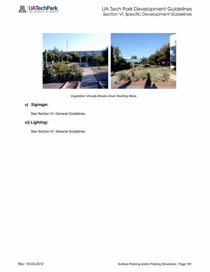
UA Tech Park Development Guidelines Section VI: Specific Development Guidelines
Rev: 10-03-2012 Surface Parking and/or Parking Structures: Page 181
Vegetation Visually Breaks Down Building Mass.
v) Signage:
See Section IV: General Guidelines.
vi) Lighting:
See Section IV: General Guidelines.

UA Tech Park Development Guidelines Section VI: Specific Development Guidelines
Rev: 10-03-2012 Hospitality: Page 182
Hospitality Hospitality uses allow for the development of a destination business-class hotel, with executive training conference center, hospitality casitas or villages, golf club house and support retail facilities adjacent to the 18-hole golf course, providing a variety of amenities to UA Tech Park tenants, visitors, and the surrounding community. All development within this area will utilize off-site utility systems. Hospitality areas must adhere to the following development standards and design guidelines as well as to the General Guidelines provided in Section IV.
Design Concept Hospitality land uses are located north of the Kolb Road Signature entrance of the UA Tech Park as shown in Figure 2. The design concept for these uses must accommodate existing access off I-10 via Kolb Road.
These Hospitality areas will enhance the Kolb Road Signature entrance to the UA Tech Park through the provision of a Signature Entry Boulevard. and hospitality uses located at a this main gateway of the UA Tech Park must reflect the UA Tech Park’s design concept and allow future development within this area to harmonize patterns of the past while introducing entirely new dynamics of community character that respond to adjacent development.
The following goals must guide hospitality development within this area: Orient hospitality areas to maintain view corridors and take advantage of mountain views, and views
to the golf course, the Solar Zone and the Julian Wash Regional Trail System.
Harmonize patterns of the past (e.g. Southwest architectural themes and styles) while introducing entirely new dynamics of community character by articulating building styles for hotel, retail, and support facilities in a manner that is responsive to adjacent development and to the overall high-tech character of the UA Tech Park creating a placemaking fusion that is unique to the UA Tech Park.
Include public art, courts, plazas, paseos, and pocket parks in the overall design.
Provide connectivity to UA Tech Park pedestrian walkways, bicycle routes, nature trail systems and the Julian Wash Regional Trail System.
Include multimodal linkages to adjacent regional commercial, golf course, and golf clubhouse.
Design street and avenue scenes to convey arrival to a destination business-class hotel.
Provide a mix of uses that include, but are not limited to, executive training conference center, 18-hole golf course and associated golf club house, community amenities such as health centers and recreational facilities, and associated retail, service, and support facilities.
Locate golf course tees within the Golf Course land use designation.
Provide convenient, accessible, and visually pleasing parking areas.
Identify opportunities for parking structures within this area to liberate additional land for other desired land uses, allowing more efficient, cohesive, and user friendly design, provided that the parking structure height does not exceed the permitted height within the Hospitality areas. Such parking structures must be integrated with hospitality design and architecturally complement hospitality buildings.
Locate hospitality, support services, and commercial/retail-dominant uses in close proximity to the Kolb Road Signature Boulevard.
Ensure that uses in the hospitality area complement the adjacent Regional Commercial uses and serve UA Tech Park tenants, visitors, and residents as well as adjacent neighborhoods.

UA Tech Park Development Guidelines Section VI: Specific Development Guidelines
Rev: 10-03-2012 Hospitality: Page 183
Locate casitas or hospitality villages in close proximity to the golf course, club house, and recreational amenities.
Integrate retail and service uses with hospitality uses.
In addition to requirements provided in Section IV: General Guidelines and in Table 15, the following standards and design guidelines apply:
i) Site Planning:
Define the hospitality entrance from Science Park Drive along the Signature Entry Boulevard hotel and retail buildings through position, size, verticality, detailing, and integration with open space treatments to evoke arrival at a destination.
Position buildings along the Signature Entry Boulevard in a manner that does not block the vista to the center of the development and view corridors to mountain views.
Emphasize the interior-exterior relationship by siting, designing of buildings and selecting architectural themes and styles that harmonize with their desert setting.
Site hotel, golf club house, visitor center, and retail buildings to reflect sensitivity to the potential differences in scale between these uses.
Site buildings in a manner that acknowledges and enhances the pedestrian experience.
Encourage unique setback distances around access points to accommodate more intensive landscape and hardscape treatments.
Require retail and service-oriented uses not directly related to hospitality complex to respect the human scale, articulate the concept of a village center, and conform to the UA Tech Park Center Overlay Zone requirements included in this section.
ii) Circulation and Access:
Provide a turnabout/drop-off area for hotel buildings to enhance the entry area from Science Park Drive.
Provide multimodal connectivity by including pedestrian and bicycle linkages to adjacent uses, trails, and open space.
Stagger major entryways to hotel buildings and associated retail parking areas to avoid congestion.
Incorporate biking and pedestrian paths (particularly from golf club house) into the design/siting of hotel and its retail areas.
Provide linkages to the Julian Wash Regional Trail System.
iii) Architectural Design:
Provide enhanced architectural and landscaping options for hospitality areas and ground appropriately distinguishing these areas from retail buildings and public spaces.
Design hotel and retail buildings in an integrated manner and utilizing compatible architectural styles.
Ensure the main entrance to the hotel reflects a sense of arrival through attractive landscaping and exterior architectural treatment that makes it distinct from the rest of the buildings.
Supplement the atrium or lobby at the hotel entrance with small commercial uses to make the hotel more “visible” to the general public, and provide a source of revenue through leasing of ground-level space to retailers.

UA Tech Park Development Guidelines Section VI: Specific Development Guidelines
Rev: 10-03-2012 Hospitality: Page 184
Encourage the use of brick, high quality stone, and concrete as cladding materials for the hotel buildings and their associated retail uses, supporting Southwestern architectural styles and themes while articulating the “high-tech” architectural character of the UA Tech Park.
Ensure that building detailing is “sleek” and modern looking, not “monolithic.”
Prohibit the use of wood cladding. It is not appropriate for buildings in the desert climate.
Utilize terraces and balconies as façade treatments on the hotel to provide amenity space, create shadows on the building façade, and visually break-up the building mass.
Incorporate metal shading screens on both hotel and retail buildings to add to the modern architectural features of the UA Tech Park.
iv) Landscape:
Use accent trees with flowering color such as Palo Verde trees as identity plantings in the Signature
Entry area at Kolb Road and along the Signature Boulevard on Science Park Drive.
Use shrubs and ground covers with annual or perennial color to highlight key areas.
Provide significant landscaping at the Signature Entry, hotel main entrance and major intersections.
Mass trees to create an effect similar to native plantings in undisturbed areas.
Enhance road surfaces at the Signature Entry area and high volume pedestrian crossing points with enriched paving treatments.
Locate parking areas to minimize their visual impact.
Buffer parking areas from adjacent streets with vegetation and landscape these areas accordingly; the emphasis in this area shall be on the “pedestrian,” rather than the “vehicle”.
v) Signage:
See Section IV: General Guidelines. vi) Lighting:
See Section IV: General Guidelines.
UA Tech Park Development Guidelines Section VI: Specific Development Guidelines
Rev: 10-03-2012 Regional Commercial: Page 185
Regional Commercial The Regional Commercial land use designation is intended to deliver an interactive shopping, dining and entertainment experience in a vibrant pedestrian-oriented outdoor setting that highlights the high-tech atmosphere of the UA Tech Park. The regional commercial land use will serve as a regional center, providing easy access from Interstate 10. Permitted uses in this area include power center anchors, national retailers, specialty stores, restaurants, boutiques, theaters and entertainment venues and mixed-use development. Regional Commercial areas must adhere to the following development standards and design guidelines as well as to the general guidelines for non-residential development provided in Section IV. Design Concept Regional Commercial land uses are located south of the Kolb Road Signature entrance of the UA Tech Park as shown in Figure 2. The design concept for these uses must accommodate existing access off I-10 via Kolb Road and Science Park Drive.
Regional commercial areas will enhance the Kolb Road Signature entrance to the UA Tech Park through the provision of walking promenade along the Signature Entry Boulevard on Science Park Drive. Commercial uses located at this main gateway of the UA Tech Park must integrate Southwestern architectural styles with the “high-tech” look of UA Tech Park. This fusion will create a unique character providing seamless continuity and harmonizing patterns bridging the richness of our past with the future while celebrating innovation and technology and introducing entirely new dynamics of community character that respond to adjacent development.
The following goals must guide development within this area:
Harmonize patterns of the past (e.g. Southwest architectural themes and styles) while introducing sleek “high-tech” features that celebrate technology and innovation in a manner that is responsive to adjacent development and to the overall character of the UA Tech Park.
Include public art, courts, plazas, paseos, and pocket parks in the overall design.
Provide pedestrian, bicycle, and nature trail connectivity to adjacent residential areas.
Include safe, convenient and efficient pedestrian and bicycle crossings on Science Park Drive linking regional commercial uses to hospitality, golf course, and golf clubhouse.
Design street and avenue scenes to convey arrival to a mixed-use destination.
Provide a mix of uses that include, but are not limited to, power center anchors, national retailers, specialty stores, restaurants, boutiques, theaters and entertainment venues, services, and mixed-use development with retail on their ground levels.
Provide convenient, accessible, and visually pleasing parking areas.
Identify opportunities for parking structures within this area to liberate additional land for other desired land uses, allowing more efficient, cohesive, and user friendly design, provided that the parking structure height does not exceed the permitted height within the Regional Commercial areas. Such parking structures must be integrated with regional commercial design and architecturally complement commercial buildings.
Ensure that commercial/retail uses in close proximity to the Kolb Road Signature Entry serve adjacent uses by providing an inviting face to Kolb Road, Science Park Drive and other development within the Regional Commercial parcel.
Provide ample opportunities for shaded walking and window shopping.

UA Tech Park Development Guidelines Section VI: Specific Development Guidelines
Rev: 10-03-2012 Regional Commercial: Page 186
Uses located adjacent to residential areas should be lower density/intensity, more community oriented, and serve the adjacent residential areas.
Conform to the Tech Park Center Overlay Zone requirements included in this section.
In addition to requirements provided in Section IV: General Guidelines and in Table 15, the following standards and design guidelines apply:
i) Site Planning:
Require that commercial buildings located along the Signature Entry Boulevard define the entry from the Science Park Drive through position, size, verticality, detailing, and open space treatment.
Position commercial buildings in relation to the Signature Entry Boulevard area in a manner that does not block the vista to the center of the development.
Incorporate view corridors with mountain views in the siting of buildings.
Emphasize the interior-exterior relationship of the siting and design of the buildings to integrate the desert setting with architectural themes and styles.
Site power center anchors, national retailers, specialty stores, restaurants, boutiques, theaters and entertainment venues and mixed-use development buildings in a manner that is sensitive to the potential differences in scale between these uses.
Site buildings in a manner that acknowledges and enhances the pedestrian experience, as well as the linkages to adjacent uses and open space.
Encourage unique setback distances around access points to accommodate more intensive landscaping and hardscape treatment.
Use human scale when designing the pedestrian realm to articulate the concept of a village center, and conform to Tech Park Center Overlay Zone requirements included in this section.
ii) Circulation and Access:
Stagger entryways to the regional commercial parking areas to avoid congestion.
Provide multimodal connectivity by including pedestrian and bicycle linkages to adjacent uses, trails, and open space.
Incorporate biking and pedestrian paths into the design/siting of regional commercial areas.
iii) Architectural Design:
Provide enhanced architectural and landscaping options for mixed-use areas appropriately distinguishing these areas from commercial buildings and public spaces.
Design commercial and mixed-use buildings in an integrated manner and utilizing compatible architectural styles.
Ensure the main entrance to the regional commercial area reflects a sense of arrival through attractive landscaping and exterior architectural treatment that makes it distinct from the rest of the buildings.
Supplement mixed-use areas with small commercial uses at ground level to increase Walkability and enhance the pedestrian experience, and provide a source of revenue through leasing of ground-level space to retailers.

UA Tech Park Development Guidelines Section VI: Specific Development Guidelines
Rev: 10-03-2012 Regional Commercial: Page 187
Encourage the use of brick, high quality stone, and concrete as cladding materials, supporting Southwestern architectural styles and themes while articulating the “high-tech” architectural character of the UA Tech Park.
Ensure that building detailing is “sleek” and modern looking, not “monolithic.”
Prohibit the use of wood cladding. It is not appropriate for buildings in the desert climate.
Utilize terraces and balconies as façade treatments on mixed-use areas to provide amenity space, create shadows on the building façade, and visually break-up the building mass.
Incorporate metal shading screens on buildings to add to the modern architectural features of the UA Tech Park.
iv) Landscape:
Use accent trees with flowering color such as Palo Verde trees as identity plantings in the Signature
Entry area at Kolb Road and along the Signature Boulevard on Science Park Drive.
Use shrubs and ground covers with annual or perennial color to highlight key areas.
Provide significant landscaping at the Signature Entry and commercial center entrances.
Mass trees to create an effect similar to native plantings in undisturbed areas.
Enhance road surfaces at the Signature Entry area and high volume pedestrian crossing points with enriched paving treatments.
Locate parking areas to minimize their visual impact.
Buffer parking areas from adjacent streets with vegetation and landscape these areas accordingly; the emphasis in this area shall be on the “pedestrian,” rather than the “vehicle”.
v) Signage:
See Section IV: General Guidelines. vi) Lighting:
See Section IV: General Guidelines.

UA Tech Park Development Guidelines Section VI: Specific Development Guidelines
Rev: 10-03-2012 UA Tech Park Plaza Overlay Zone: Page 188
UA Tech Park Plaza Overlay Zone A floating overlay zone not delineated in the UA Tech Park Land Use Plan is the UA Tech Park Plaza. The UA Tech Park Plaza or pedestrian mall is located adjacent to the developed Research Park. This overlay zone will include walkways and bicycle access as well as landscaped amenities providing connectivity to the Rita Road signature entry or main gateway and the regional trail system. This form of open space is designed to define a placemaking destination, to provide connectivity between Research Park and Business Development uses, to provide linkages to the UA Tech Park and the regional trail systems and to serve UA Tech Park tenants, users, visitors, and surrounding community, enhancing Walkability and connectivity throughout the UA Tech Park.
In addition to requirements provided in Table 15 of this volume and in the general guidelines for non-residential development provided in Section IV, the following standards and design guidelines apply: i) Site Planning:
Orient the central Plaza or central open space/green mall in a manner that integrates new and existing development, respects view corridors, and provides a visual relief to adjacent development.
Establish a pedestrian-centered rest area or central open space/green mall including pedestrian and bicycle access.
The UA Tech Plaza functions as a “third place for science and technology” providing physical and visual relaxation to workers, scientists, students and visitors.
Site design is formal along the Plaza with meandering paths providing pedestrian and bicycle connectivity to adjacent uses.

UA Tech Park Development Guidelines Section VI: Specific Development Guidelines
Rev: 10-03-2012 UA Tech Park Plaza Overlay Zone: Page 189
ii) Circulation and Access:
Establish a hierarchy of circulation within the UA Tech Park Plaza through path width, character, and vegetation:
Design the central pedestrian mall/green space with a strong linear design, providing paths along its edges ‘broken’ by activity nodes, seating alcoves, public art, or sculpture/planter boxes to provide for a more interesting visual experience.
Link uses on both sides of the central pedestrian mall/green area with NE-SW and NW-SE paths that are ‘meandering’ in nature and provide pedestrian and bicycle connectivity to adjacent uses, buildings, parking, cafeteria.
Provide bicycle parking in the periphery of the central pedestrian mall/green space in close proximity to adjacent buildings.
iii) Architectural Design:
Require that bicycle parking, hardscapes, benches, small fences, seating alcoves and public art
are compatible in style with adjacent architectural styles and with the overall high-tech look of the UA Tech Park.
Utilize materials, colors and design palettes that complement adjacent buildings. iv) Landscape
Reduce heat island effect and increase UA Tech Park sustainability by ensure that major
landscaping objectives are low-water consumption and low maintenance throughout the area by adhering to the following:
Select native or drought-tolerant vegetation listed in the Plant Palette provided in Appendix A.
Incorporate water harvesting methods and techniques.
Utilize solar-powered drip irrigation where effective and feasible.
Use recycled water or harvested water for ponds and water features within this area.
Use vegetation to establish hierarchy and direct pedestrian movement (through linear planting schemes) and to define space for picnic areas and outdoor relaxation areas through more organic schemes as follows:
Plant Palo Verde trees in linear planting schemes along the edges of the plaza to direct pedestrian movement.
Plant trees that provide shade at maturity in seating areas in accordance with Plant Palettes provided in Appendix A.
Construct covered walkways near buildings to emphasize physical linkages to the Plaza and to provide shade during hot summer months.
Provide a variety of seating areas in the Plaza for groups/individuals.
Use berming, rock outcroppings, public art, and ponds (retention/detention) shall be used throughout the Plaza to provide visual interest and create a more natural lush desert look.
Public art and signage shall be provided at locations deemed to be important focal points and as way-finding elements.

UA Tech Park Development Guidelines Section VI: Specific Development Guidelines
Rev: 10-03-2012 UA Tech Park Plaza Overlay Zone: Page 190
Illustration 64: Rock Outcroppings Function as Sculptural Elements, Reinforce Landscape Design, and Complement Architectural Styles.
v) Signage:
See signage chapter provided in Section IV: General Guidelines. vi) Lighting:
See lighting chapter provided in Section IV: General Guidelines.

UA Tech Park Development Guidelines Section VI: Specific Development Guidelines
Rev: 10-03-2012 UA Tech Park Center Overlay: Page 191
UA Tech Park Center Overlay A floating overlay zone not delineated in the UA Tech Park Master Plan is the UA Tech Park Center Overlay Zone. This overlay zone provides specific guidelines for regional commercial, retail, and hospitality development along Kolb Road and immediately adjacent to the UA Tech Park hotel. This overlay zone will help define the UA Tech Park Center or core bridging the Regional Commercial and Hospitality parcels and articulating the transition from higher-intensity uses to less-intensity ones. This core will provide a focal gathering center for UA Tech Park tenants, users and visitors and will support the golf course and the golf course club house as well as adjacent conference center, hospitality development, retail, office, and residential uses. Design Concept UA Tech Park Center Overlay Zone The UA Tech Park Center Overlay Zone is located in close proximity to the Regional Commercial and Hospitality, Golf Course, and Residential uses. Entrance to the UA Tech Park Center via the Kolb Road Signature entry or the existing Kolb entrance to the UA Tech Park will be provided by Science Park Drive, the primary east-west spine road shown in Figure 2. The proposed UA Tech Park Center Overlay is a mixed-use office and service commercial village containing retail, employment, governmental offices, and recreation facilities and providing services to UA Tech Park tenants, visitors, and residents.
The following goals must guide development within this area:
Provide ample opportunities for public art, pedestrian walkways and bicycle routes, courts, plazas, paseos, and pocket parks.
Include linkages to Residential, Regional Commercial and Hospitality land uses as well as to golf course and golf club house.
Design 250’–300’ building blocks, about the size of an urban village grid street system.
Development character could include street and avenue scenes with varying mixes of employee services, offices, recreational facilities, governmental offices, and community amenities, such as health centers and recreation facilities as well as connectivity to the golf course.
Provide parking in smaller increments and require that parking areas are distributed for greater convenience.
In addition to requirements provided in Section IV: General Guidelines (non-residential uses), the following standards and design guidelines apply:
i) Site Planning:
Physically define the entrance of retail buildings located in close proximity to the primary or secondary road through position, size, verticality, detailing and open space treatment in a manner that defines the pedestrian realm.
Position buildings in the major entry area to take advantage of mountain views and views into the center of the regional commercial development.
Emphasize the interior-exterior relationship of the siting and design of the buildings by adding elements that emphasize human scale and building transparency to create an inviting pedestrian-realm.
Site golf course house, recreational facilities, and retail buildings to articulate the potential differences in scale between these uses.

UA Tech Park Development Guidelines Section VI: Specific Development Guidelines
Rev: 10-03-2012 UA Tech Park Center Overlay: Page 192
Acknowledge and enhance the pedestrian experience by appropriately siting buildings to foster walkability and to provide connectivity to adjacent uses, walkways, bikeways and open spaces.
ii) Circulation and Access:
Stagger major entryways to parking areas to avoid congestion.
Incorporate safe, efficient, and convenient access to pedestrians and bicycle uses at pedestrian crossings along Science Park Drive.
Provide safe, efficient, and convenient access to pedestrian, bicycle, transit, shuttle, and vehicular modes to Regional Commercial, Residential and Hospitality uses on both sides of Science Park Drive.
Require all development to provide safe, effective and convenient pedestrian and bicycle connectivity within the Park Center and with adjacent uses.
iii) Architectural Design:
Encourage brick, high quality stone, and concrete as cladding materials for retail buildings while ensuring that building appearance reflects, harmonizes or complements the overall “high-tech” architectural character of the park by:
Providing building detailing that is “sleek” and modern looking, not “monolithic.”
Encouraging transparent façades with metal details and metal shading screens that are modern, sleek and add to the high-tech architectural features of the UA Tech Park.
Prohibit the use of wood cladding. This material is not appropriate for buildings in the desert climate and should not be used.
Require retail buildings to show a human scale and enhance the pedestrian experience with glazing at street level to allow for “window shopping”.
Include terraces and balconies as façade treatments on buildings to provide amenity space, create shadows on the building façade, and visually break-up the building mass.
iv) Landscape:
Plant accent trees with flowering color as identity plantings in both pedestrian and vehicular entry
areas.
Plant shrubs and ground covers with annual or perennial color to highlight key areas.
Provide significant landscaping at major entryways and include minor landscape treatments at secondary entryways creating a hierarchy that assist in wayfinding.
Mass trees to create an effect similar to native plantings in undisturbed areas.
Enhance road surfaces at the entry area and high volume pedestrian crossings with enriched paving treatments.
Locate parking areas to minimize their visual impact and provide vegetation screens to enhance public right-of-ways and landscape accordingly. The emphasis in this area shall be on the “pedestrian,” rather than the “vehicle”.
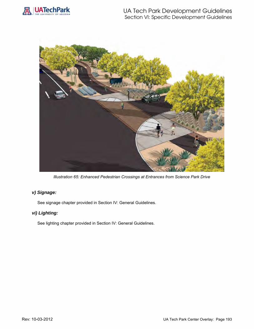
UA Tech Park Development Guidelines Section VI: Specific Development Guidelines
Rev: 10-03-2012 UA Tech Park Center Overlay: Page 193
Illustration 65: Enhanced Pedestrian Crossings at Entrances from Science Park Drive v) Signage:
See signage chapter provided in Section IV: General Guidelines. vi) Lighting:
See lighting chapter provided in Section IV: General Guidelines.

UA Tech Park Development Guidelines Section VI: Specific Development Guidelines
Rev: 10-03-2012 Low-Intensity Office Overlay Zone: Page 194
Low-Intensity Office Overlay Zone The Low Intensity Office Overlay Zone is located north of Science Park Drive and overlays the Open Space/Golf Course land use designation. This overlay consists of three ten-acre office parcels that will function as a professional center area designed to accommodate a mix of business, professional, research services, and office uses which have unusual requirements for space, light, and air, and the operations of which are clean and quiet and support other UA Tech Park uses. Design Concept Low-Intensity Overlay Zone The Low-Intensity Office Overlay Zone will encompass a maximum of 30 acres north of Science Park Drive, the east-west primary road. Development within this overlay zone will have a small business park setting, respond to adjacent golf course, and conform to the employee density requirements of 25 employees per aggregate acre. Uses permitted within this overlay zone include: small-scale professional offices for architects, engineers, and other professional services; small-scale research institutes; mail and package services; express mail and delivery service offices; post office boxes; bookbinding, printing, and lithographic services; editorial and designing; printing and cartographic services; and art studios. Additional uses may be permitted provided they are compatible with adjacent development and require Office of University Research Parks Design Review Committee approval. The location of these low-intensity business parks will respond to market forces. This overlay zone must adhere to the following development standards and design guidelines as well as to the General Guidelines for non-residential development provided in Section IV. The following goals must guide development within this overlay zone: Provide access to UA Tech Park pedestrian walkways and bicycle routes.
Include linkages to Residential, Research Park, Regional Commercial, Hospitality and Business Development land uses as well as to golf course and golf club house.
Provide parking in smaller increments and require that parking areas are shared and distributed for greater convenience.
In addition to compliance with all applicable development standards, guidelines and setbacks included in Section IV and on Table 15, the following standards and design guidelines apply:
i) Site Planning:
Define the entrance from the Science Park Drive entry area through position of buildings, size, detailing, and open space treatment.
Site and position buildings to maintain mountain-view corridors and views to the center of the development.
Emphasize the interior-exterior relationship of the siting and design of the buildings.

UA Tech Park Development Guidelines Section VI: Specific Development Guidelines
Rev: 10-03-2012 Low-Intensity Office Overlay Zone: Page 195
Site buildings to acknowledge and enhance the pedestrian experience, as well as the linkages to adjacent uses and open space.
Provide a landscaped buffer as indicated in the following table:
Table 16: Required Landscaped Buffers within the Low Intensity Office Overlay Zone
Adjacent Land Use
Landscaped Buffer Width
(Feet)
Other Business/Office Parks 10
Solar Zone Access Road 10
Golf Course 10
Equestrian Trails 10
Walkways and Bike Routes 10
Note: The 10 ft. landscaped buffer must be located within the 20 ft. setback. Equestrian trails, walkways, and bike routes may be included within the 20 ft. setback.
ii) Circulation and Access:
See Chapter C, Section IV: General Guidelines.
Incorporate connectivity to pedestrian and bicycle paths, particularly from the Hospitality and Golf Course areas, into the design/siting of buildings located within this overlay zone.
iii) Architectural Design:
See Chapter F, Section IV: General Guidelines.
Encourage brick, high quality stone, and concrete as cladding materials for retail buildings while ensuring that building appearance reflects, harmonizes or complements the overall “high-tech” architectural character of the park by:
Providing building detailing that is “sleek” and modern looking, not “monolithic.”
Encouraging transparent façades with metal details and metal shading screens that are modern, sleek and add to the high-tech architectural features of the UA Tech Park.
Prohibit the use of wood cladding. This material is not appropriate for buildings in the desert climate and should not be used.
Add metal shading screens on buildings that reflect the high-tech contemporary architectural features of the UA Tech Park.

UA Tech Park Development Guidelines Section VI: Specific Development Guidelines
Rev: 10-03-2012 Low-Intensity Office Overlay Zone: Page 196
iv) Landscape:
See Chapter G, Section IV: General Guidelines
Plant accent trees with flowering color as identity plantings in both pedestrian and vehicular entry areas.
Plant shrubs and ground covers with annual or perennial color to highlight key areas.
Provide significant landscaping at major entryways and include minor landscape treatments at secondary entryways creating a hierarchy that assist in wayfinding.
Mass trees to create an effect similar to native plantings in undisturbed areas.
Enhance road surfaces at the entry area and high volume pedestrian crossings with enriched paving treatments.
Locate parking areas to minimize their visual impact and provide vegetation screens to enhance public right-of-ways and landscape accordingly. The emphasis in this area shall be on the “pedestrian,” rather than the “vehicle”.
v) Signage:
See signage chapter provided in Section IV: General Guidelines. vi) Lighting:
See lighting chapter provided in Section IV: General Guidelines.

UA Tech Park Development Guidelines Section VI: Specific Development Guidelines
Rev: 10-03-2012 Davis-Monthan Air Force Base Dedicated Open Space Corridor: Page 197
Davis-Monthan Air Force Base Dedicated Open Space Corridor In addition to the 25% open space required at parcel level, the UA Tech Park designates 136 acres as the Davis-Monthan AFB Dedicated Open Space Corridor. This corridor supports Davis-Monthan AFB flight operations and provides for a mix of riparian habitat, naturally occurring washes, archaeological and cultural resources, and recreational uses such as linear park and golf courses. The Julian Wash Regional Trail is located within this corridor. The Agriculture/Research Overlay Zone is also located within the Corridor. In addition to requirements provided in Table 15, Chapter K: Open Space included in Section IV: General Guidelines must be consulted.
UA Tech Park Development Guidelines Section VI: Specific Development Guidelines
Rev: 10-03-2012 Davis-Monthan AFB Approach/Departure Corridor: Standards for Development: Page 198
Davis-Monthan AFB Approach/Departure Corridor: Standards for Development
The Arizona Military Regional Compatibility Project Davis-Monthan Air Force Base/Tucson/Pima County Joint Land Use Study (JLUS) recommends that development in the UA Tech Park proceeds under the UA Tech Park’s adopted Development Guidelines, provided that:
Density transfers are used within the UA Tech Park to shift employee density from the northern part of the UA Tech Park to the southern part;
Development of the UA Tech Park within the D-M AFB 0-30,000 ft. ADC be limited to employment-generating uses;
Hotel and child care facilities not be developed within this portion of the ADC; and Existing high school use is relocated outside this ADC.
According to the JLUS, compatible uses within the D-M AFB 0-30,000 ft. ADC are non-residential uses that have relatively low employment density (number of persons per acre). These are primarily industrial uses, along with other uses that have low concentrations of persons, such as certain types of outdoor recreation.
The UA Tech Park is the largest single-owned parcel located within the Davis-Monthan AFB Approach/Departure Corridor. The UA Tech Park comprises 1,345 acres, or 21 percent of the total 6,216 acres Approach/Departure Corridor. Most of the UA Tech Park is located inside this corridor. Of the total 1,345-Park acreage, approximately 1,074 acres, or 80 percent, are located inside the ADC as follows: approximately 1,028 acres, or 76.4 percent, are located inside the 0-30,000 ft. ADC; approximately 46 acres, or 3.4 percent, are located inside the 30,000-50,000 ft. ADC. UA Tech Park lands located outside the ADC encompass approximately 189 acres, or 14 percent, of the total UA Tech Park acreage. Development within areas of the UA Tech Park designated Research Park is grandfathered and will continue to develop at the densities established. Development outside of the Research Park designation and within the 0-30,000 ft. ADC is limited to an “aggregate employee density” of 20 employees per acre for aggregate lands owned by the University of Arizona, and to an “employee density” of 20 employees per acre for lands not owned by the University of Arizona. Development outside of the Research Park designation and within the 30,000-50,000 ft. ADC is limited to 40% site coverage for industrial, wholesaling and manufacturing uses and to 20% site coverage for other non-residential uses.
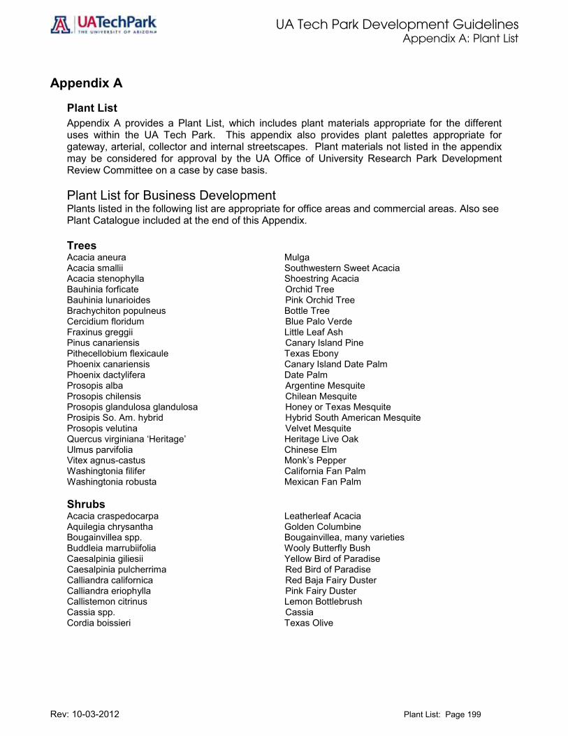
UA Tech Park Development Guidelines Appendix A: Plant List
Rev: 10-03-2012 Plant List: Page 199
Appendix A
Plant List Appendix A provides a Plant List, which includes plant materials appropriate for the different uses within the UA Tech Park. This appendix also provides plant palettes appropriate for gateway, arterial, collector and internal streetscapes. Plant materials not listed in the appendix may be considered for approval by the UA Office of University Research Park Development Review Committee on a case by case basis. Plant List for Business Development Plants listed in the following list are appropriate for office areas and commercial areas. Also see Plant Catalogue included at the end of this Appendix. Trees Acacia aneura Mulga Acacia smallii Southwestern Sweet Acacia Acacia stenophylla Shoestring Acacia Bauhinia forficate Orchid Tree Bauhinia lunarioides Pink Orchid Tree Brachychiton populneus Bottle Tree Cercidium floridum Blue Palo Verde Fraxinus greggii Little Leaf Ash Pinus canariensis Canary Island Pine Pithecellobium flexicaule Texas Ebony Phoenix canariensis Canary Island Date Palm Phoenix dactylifera Date Palm Prosopis alba Argentine Mesquite Prosopis chilensis Chilean Mesquite Prosopis glandulosa glandulosa Honey or Texas Mesquite Prosipis So. Am. hybrid Hybrid South American Mesquite Prosopis velutina Velvet Mesquite Quercus virginiana ‘Heritage’ Heritage Live Oak Ulmus parvifolia Chinese Elm Vitex agnus-castus Monk’s Pepper Washingtonia filifer California Fan Palm Washingtonia robusta Mexican Fan Palm Shrubs Acacia craspedocarpa Leatherleaf Acacia Aquilegia chrysantha Golden Columbine Bougainvillea spp. Bougainvillea, many varieties Buddleia marrubiifolia Wooly Butterfly Bush Caesalpinia giliesii Yellow Bird of Paradise Caesalpinia pulcherrima Red Bird of Paradise Calliandra californica Red Baja Fairy Duster Calliandra eriophylla Pink Fairy Duster Callistemon citrinus Lemon Bottlebrush Cassia spp. Cassia Cordia boissieri Texas Olive

UA Tech Park Development Guidelines Appendix A: Plant List
Rev: 10-03-2012 Plant List: Page 200
Shrubs (continued) Dalea bicolor v. bicolor Monterrey Blue Dalea frutescens Sierra Negra Dalea pulchra Indigo Bush Eremophila spp. Emu Bush Feijoa sellowiana Pineapple Guava Justicia spicigera Mexican Honeysuckle Lagerstroemia indica – many cvs. Crape Myrtle – many cultivars Lantana camera – many cvs. Bush Lantana – many cultivars Leucophyllum frutescens spp. Texas Ranger Myrtus communis True Myrtle, Roman Myrtle Myrtus communis ‘Compacta’ Dwarf Myrtle Nandina domestica Heavenly Bamboo, Nandina Nandina domestica ’Compacta’ Compact Nandina Nandina domestica ‘Nana’ Dwarf Nandina Nerium oleander Oleander Photinia fraseri Photinia Pittosporum tobira Tobira, Mock Orange Pittosporum tobira ‘Variegata’ Variagated Tobira, Mock Orange Plumbago scandens Summer Snow Podocarpus macrophyllus Yew Pine Rosa banksiae Lady Banks’ Rose Rosmarinus officinalis Rosemary Rhus ovata Sugar Bush Ruellia brittoniana Blue Ruellia Ruellia peninsularis Desert Ruellia Salvia chamaedroyides Mexican Blue Sage Salvia clevelandii Chaparral Sage Salvia greggii Red Sage Salvia leucantha Mexican Bush Sage Simmondsia chinensis Jojoba Simmondsia chinensis ‘Vista’ Compact Jojoba Sophora secundiflora Texas Mountain Laurel, Mescal Bean Strelitzia reginae Red Bird of Paradise Tagetes spp. – many cvs. Marigold – many cultivars Tecoma stans Trumpet Bush, Yellow Trumpet Tecomaria capensis Cape Honeysuckle Vauquelinia californica Arizona Rosewood Xylosma congestum Xylosma

UA Tech Park Development Guidelines Appendix A: Plant List
Rev: 10-03-2012 Plant List: Page 201
Ground Covers Acacia redolens ‘Desert Carpet’ Trailing Acacia Asparagus densiflorus “Spengeri” Asparagus Fern Calylophus hartwegii Sierra Sundrop Carpobrotus edulis Ice Plant, Hottentot Fig Convolvulus cneorum Bush Morning Glory Dalea greggii Trailing Indigo Bush Lantana montevidensis Trailing Lantana Liriope muscari spp. Lily Turf Myoporum parvifolium Prostrate Myoporum Ophiopogon japonicus Mondo Grass Rosmarinus officinalis ‘Prostratus’ Dwarf Rosemary Verbena spp. Verbena Vinca major Periwinkle Vinca major ‘Variegata’ Variegated Periwinkle Accent & Vines Agave gemniflora Twin-flowered Agave Agave murpheyi Murphy Agave Agave victoriae-reginae Queen Victoria Agave Agave vilmoriniana Octopus Agave Aloe barbadensis Aloe Vera, Medicinal Aloe Aloe ferox Cape Aloe Aloe saponaria Mediterranean Aloe Antigonon leptopus Queen’s Wreath Carnegiea gigantea Saguaro, Sahuaro Chamaerops humilis Mediterranean Fan Palm Dasylirion longissimum Toothless Desert Spoon Dasylirion texanum Green Desert Spoon Dasylirion wheeleri Desert Spoon, Sotol Echinocactus grusonii Golden Barrel Euphorbia biglandulosa Gopher Plant Ficus pumila Creeping Fig Fouquieria splendens Ocotillo Hesperaloe parviflora Red Yucca Lonicera japonica ‘Halliana’ Hall’s Honeysuckle Macfadyena unguis-cacti Cat’s Claw, Funnel Creeper Muhlenbergia capillaries Regal Mist Muhlenbergia lindheimeri Autumn Glow Muhlenbergia rigida Nashville Nolina bigelovii Bigelow Nolina Nolina microcarpa Bear Grass Oenothera berlandieri Mexican Evening Primrose Oenothera caespitosa White Evening Primrose Opuntia basilaris Beavertail Prickly Pear Opuntia ficus-indica Tuna Cactus, Spineless Cactus Opuntia violacea santa-rita Purple Prickly Pear Osteospermum fruticosum White Trailing African Daisy Pennisetum setaceum ‘Cupreum’ Purple Fountain Grass Penstemon spp. Penstemon Philodendron selloum Philodendron, Selloum Yucca spp. Yucca

UA Tech Park Development Guidelines Appendix A: Plant List
Rev: 10-03-2012 Plant List: Page 202
Commercial/Hospitality Areas Plants listed in the following list are appropriate for Commercial/Hospitality areas. Trees Acacia aneura Mulga Acacia stenophylla Shoestring Acacia Bauhinia forficata Orchid Tree Bauhinia lunarioides Pink Orchid Tree Brachychiton populneus Bottle Tree Callistemon citrinus Lemon Bottlebrush Cercidium floridum Blue Palo Verde Cercidium microphyllum Littleleaf or Foothill Palo Verde Citrus spp. Citrus Cupressus sempervirens Italian Cypress Fraxinus greggii Little Leaf Ash Magnolia grandiflora Southern Magnolia Phoenix canariensis Canary Island Date Palm Phoenix dactylifera Date Palm Pinus canariensis Canary Island Pine Pithecellobium flexicaule Texas Ebony Platanus wrighti Arizona Sycamore, Plane Tree Podocarpus macrophyllus Yew Pine Prosopis alba Argentine Mesquite Prosopis chilensis Chilean Mesquite Prosopis glandulosa glandulosa Honey or Texas Mesquite Prosipis So. Am. hybrid Hybrid South American Mesquite Prosopis velutina Velvet Mesquite Quercus virginiana ‘Heritage’ Heritage Live Oak Trachycarpus fortunei Windmill Palm Ulmus parvifolia Chinese Elm Vitex agnus-castus Monk’s Pepper Washingtonia filifer California Fan Palm Washingtonia robusta Mexican Fan Palm Shrubs Acacia craspedocarpa Leatherleaf Acacia Aquilegia chrysantha Golden Columbine Buddleia marrubiifolia Wooly Butterfly Bush Caesalpinia gillesii Yellow Bird of Paradise Caesalpinia pulcherrima Red Bird of Paradise Calliandra californica Red Fairy Duster Calliandra eriophylla Pink Fairy Duster
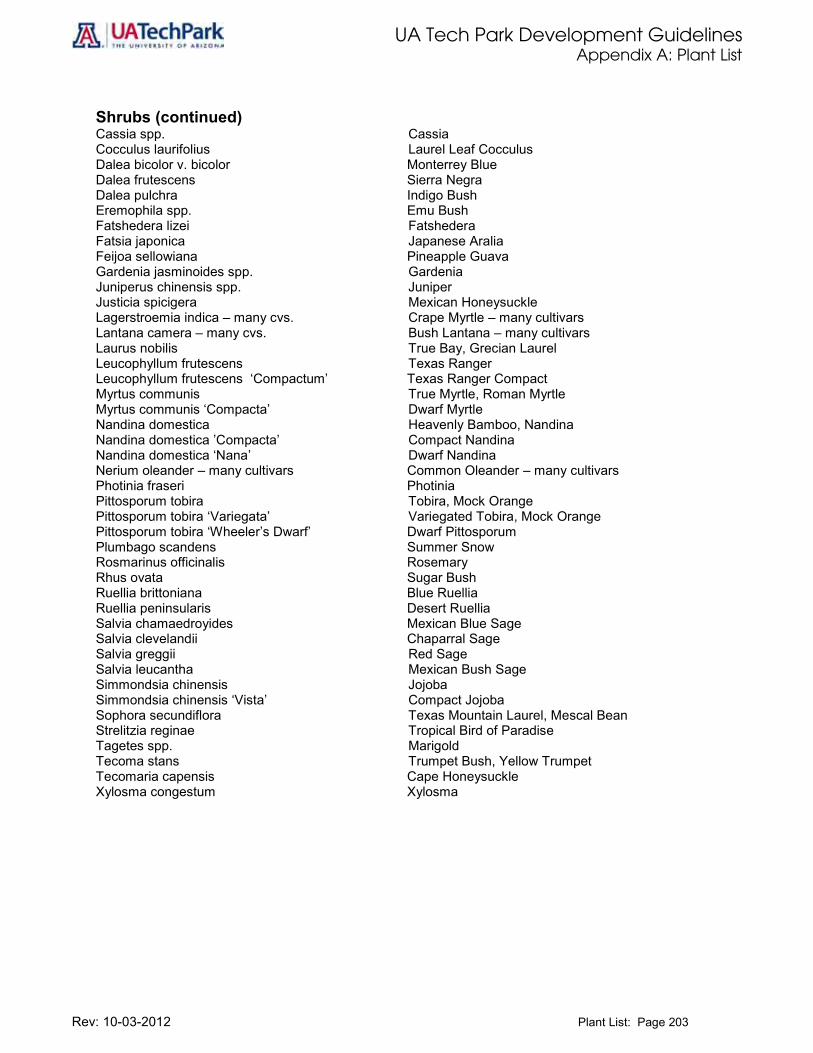
UA Tech Park Development Guidelines Appendix A: Plant List
Rev: 10-03-2012 Plant List: Page 203
Shrubs (continued) Cassia spp. Cassia Cocculus laurifolius Laurel Leaf Cocculus Dalea bicolor v. bicolor Monterrey Blue Dalea frutescens Sierra Negra Dalea pulchra Indigo Bush Eremophila spp. Emu Bush Fatshedera lizei Fatshedera Fatsia japonica Japanese Aralia Feijoa sellowiana Pineapple Guava Gardenia jasminoides spp. Gardenia Juniperus chinensis spp. Juniper Justicia spicigera Mexican Honeysuckle Lagerstroemia indica – many cvs. Crape Myrtle – many cultivars Lantana camera – many cvs. Bush Lantana – many cultivars Laurus nobilis True Bay, Grecian Laurel Leucophyllum frutescens Texas Ranger Leucophyllum frutescens ‘Compactum’ Texas Ranger Compact Myrtus communis True Myrtle, Roman Myrtle Myrtus communis ‘Compacta’ Dwarf Myrtle Nandina domestica Heavenly Bamboo, Nandina Nandina domestica ’Compacta’ Compact Nandina Nandina domestica ‘Nana’ Dwarf Nandina Nerium oleander – many cultivars Common Oleander – many cultivars Photinia fraseri Photinia Pittosporum tobira Tobira, Mock Orange Pittosporum tobira ‘Variegata’ Variegated Tobira, Mock Orange Pittosporum tobira ‘Wheeler’s Dwarf’ Dwarf Pittosporum Plumbago scandens Summer Snow Rosmarinus officinalis Rosemary Rhus ovata Sugar Bush Ruellia brittoniana Blue Ruellia Ruellia peninsularis Desert Ruellia Salvia chamaedroyides Mexican Blue Sage Salvia clevelandii Chaparral Sage Salvia greggii Red Sage Salvia leucantha Mexican Bush Sage Simmondsia chinensis Jojoba Simmondsia chinensis ‘Vista’ Compact Jojoba Sophora secundiflora Texas Mountain Laurel, Mescal Bean Strelitzia reginae Tropical Bird of Paradise Tagetes spp. Marigold Tecoma stans Trumpet Bush, Yellow Trumpet Tecomaria capensis Cape Honeysuckle Xylosma congestum Xylosma

UA Tech Park Development Guidelines Appendix A: Plant List
Rev: 10-03-2012 Plant List: Page 204
Ground Covers Acacia redolens ‘Desert Carpet’ Trailing Acacia Asparagus densiflorus “Spengeri” Sprenger’s Asparagus Calylophus hartwegii Sierra Sundrop Carpobrotus edulis Ice Plant, Hottentot Fig Convolvulus cneorum Bush Morning Glory Dalea greggii Trailing Indigo Bush Gelsemium sempervirens Carolina Jessamine Lantana montevidensis Trailing Lantana Liriope muscari spp. Lily Turf Myoporum parvifolium Prostrate Myoporum Ophiopogon japonicus Mondo Grass Rosmarinus officinalis ‘Prostratus’ Dwarf Rosemary Trachelospermum asiaticum Asiatic Jasmine Trachelospermum jasminoides Star Jasmine Verbena spp. Verbena Accent & Vines Agave gemniflora Twin-flowered Agave Agave murpheyi Murphy Agave Agave victoriae-reginae Queen Victoria Agave Agave vilmoriniana Octopus Agave Aloe barbadensis Medicinal Aloe, Aloe Vera Aloe ferox Cape Aloe Aloe saponaria Mediterranean Aloe Antigonon leptopus Queen’s Wreath Bougainvillea spp. Bougainvillea – many varieties Carnegiea gigantea Saguaro, Sahuaro Chamaerops humilis Mediterranean Fan Palm Cycas revoluta Sago Palm Dasylirion longissimum Toothless Desert Spoon Dasylirion texanum Green Desert Spoon Dasylirion wheeleri Desert Spoon, Sotol Dietes vegeta Fortnight Lily Echinocactus grusonii Golden Barrel Euphorbia biglandulosa Gopher Plant Ficus pumila Creeping Fig Fouquieria splendens Ocotillo Hesperaloe parviflora Red Yucca Lonicera japonica ‘Halliana’ Hall’s Honeysuckle Macfadyena unguis-cacti Cat’s Claw, Funnel Creeper Muhlenbergia capillaries Regal Mist Muhlenbergia lindheimeri Autumn Glow Muhlenbergia rigida Nashville Nolina bigelovii Bigelow Nolina Nolina microcarpa Bear Grass Oenothera berlandieri Mexican Evening Primrose Oenothera caespitosa White Evening Primrose Opuntia basilaris Beavertail Prickly Pear Opuntia ficus-indica Tuna Cactus, Spineless Cactus

UA Tech Park Development Guidelines Appendix A: Plant List
Rev: 10-03-2012 Plant List: Page 205
Accent & Vines (continued) Opuntia violacea santa-rita Purple Prickly Pear Osteospermum fruticosum White Trailing African Daisy Pennisetum setaceum ‘Cupreum’ Purple Fountain Grass Penstemon spp. Penstemon Philodendron selloum Philodendron, Selloum Rosa banksiae Lady Banks’ Rose Psilostrophe cooperi Paper Flower Verbena peruviana Peruvian Verbena Vinca major Periwinkle Vinca major ‘Variegata’ Variegated Periwinkle Yucca spp. Yucca Streetscape Plant List Plants included in the following list are appropriate for gateway, primary and secondary roads within the Tech Park. Trees Acacia smallii Southwestern Sweet Acacia Acacia stenophylla Shoestring Acacia Brachychiton populneus Bottle Tree, Kurrajong Carya illinoinensis - many cvs. Pecan - many cultivars Cedrus deodara Deodara Cedar Cercidium floridum Blue Palo Verde Cupressus arizonica Rough Barked Arizona Cypress Cupressus glabra Smooth Barked Arizona Cypress Eucalyptus microtheca Coolibah Eucalyptus papuana Ghost Gum Fraxinus uhdei Evergreen Ash, Shamel Ash Fraxinus velutina Arizona Ash Fraxinus velutina ‘Modesto’ Modesto Ash Fraxinus velutina ‘Rio Grande’ Fan-Tex Ash Juglans major Arizona Black Walnut Phoenix canariensis Canary Island Date Palm Phoenix dactylifera Date Palm Pinus halepensis Aleppo Pine Pistacia atlantica Mr. Atlas Pistache Pistacia chinensis Chinese Pistache Pistacia lentiscus Evergreen Pistache Platanus racemosa California Sycamore or Plane Tree Prosopis velutina Velvet Mesquite Quercus virginiana ‘Heritage’ Heritage Live Oak Shrubs Acacia craspedocarpa Leatherleaf Acacia Buddleia marrubiifolia Wooly Butterfly Bush Cotoneaster glaucophyllus Bright Bead Cotoneaster Cotoneaster lacteus (C.parneyi) Parney Cotoneaster Cotoneaster pannosus Silverleaf Cotoneaster

UA Tech Park Development Guidelines Appendix A: Plant List
Rev: 10-03-2012 Plant List: Page 206
Shrubs (continued) Dalea bicolor v. bicolor Monterrey Blue Dalea frutescens Sierra Negra Dalea pulchra Indigo Bush Feijoa sellowiana Pineapple Guava Juniperus chinensis spp. Juniper Lantana camera – many cvs. Bush Lantana – many cultivars Leucophyllum frutescens Texas Ranger Leucophyllum frutescens ‘Compactum’ Compact Texas Ranger. Myrtus communis True Myrtle, Roman Myrtle Myrtus communis ‘Compacta’ Dwarf Myrtle Nerium oleander Oleander Pennisetum setaceum ‘Cupreum’ Purple Fountain Grass Photinia fraseri Photinia Pittosporum tobira Tobira, Mock Orange Pittosporum tobira ‘Variegata’ Tobira, Mock Orange Salvia clevelandii Chaparral Sage Salvia leucantha Mexican Bush Sage Simmondsia chinensis Jojoba Simmondsia chinensis ‘Vista’ Compact Jojoba Sophora secundiflora Texas Mountain Laurel, Mescal Bean Sphaeralcea ambigua Globe Mallow Tecoma stans Trumpet Bush, Yellow Trumpet Vauquelinia californica Arizona Rosewood Viguiera deltoidea Goldeneye Ground Covers Acacia redolens ‘Desert Carpet’ Trailing Acacia Calylophus hartwegii Sierra Sundrop Lantana montevidensis Trailing Lantana Teucrium chamaedrys ‘Prostratum’ Prostrate Germander Verbena spp. Verbena Accent & Vines Agave gemniflora Twin-flowered Agave Dasylirion longissimum Toothless Desert Spoon Dasylirion texanum Green Desert Spoon Dasylirion wheeleri Desert Spoon Ficus pumila Creeping Fig Fouquieria splendens Ocotillo Hesperaloe parviflora Red Yucca Muhlenbergia capillaries Regal Mist Muhlenbergia lindheimeri Autumn Glow Muhlenbergia rigida Nashville Nolina bigelovii Bigelow Nolina Nolina microcarpa Bear Grass Oenothera berlandieri Mexican Evening Primrose Oenothera caespitosa White Evening Primrose Opuntia basilaris Beavertail Prickly Pear Opuntia ficus-indica Indian Fig

UA Tech Park Development Guidelines Appendix A: Plant List
Rev: 10-03-2012 Plant List: Page 207
Accent & Vines (continued) Opuntia violacea santa-rita Purple Prickly Pear Penstemon spp. Penstemon Psilostrophe cooperi Paper Flower Yucca spp. Yucca Plant List for Surface Parking Lots Plants included in the following list are appropriate for surface parking lots within the Sicence and Technology Park. Trees Acacia smalli Southwestern Sweet Acacia Acacia stenophylla Shoestring Acacia Brachychiton populneus Bottle Tree Cercidium floridum Blue Palo Verde Eucalyptus microtheca Coolibah Eucalyptus papuana Ghost Gum Fraxinus velutina Arizona Ash Fraxinus velutina ‘Modesto’ Modesto Ash Fraxinus velutina ‘Rio Grande’ Fan-Tex Ash Pistacia atlantica Mr. Atlas Pistache Pistacia chinensis Chinese Pistache Pistacia lentiscus Lentish or Evergreen Pistache Pithecellobium flexicaule Texas Ebony Prosopis glandulosa glandulosa Honey or Texas Mesquite Prosopis velutina Velvet Mesquite Quercus virginiana ‘Heritage’ Heritage Live Oak Shrubs Buddleia marrubiifolia Wooly Butterfly Bush Caesalpinia pulcherrima Red Bird of Paradise Calliandra californica Red Baja Fairy Duster Calliandra eriophylla False Mesquite Cassia artemisioides Wormwood Senna, Feathery Cassia Cassia eremophila Desert Cassia Dalea bicolor v. bicolor Monterrey Blue Dalea frutescens Sierra Negra Dalea pulchra Indigo Bush Dodonaea viscosa Hop Bush Dodonaea viscosa ‘Purpurea’ Purple Hop Bush Encelia farinosa Brittlebush Lantana camera – many cvs. Bush Lantana – many cultivars Nerium oleander Oleander Pennisetum setaceum ‘Cupreum’ Purple Fountain Grass Rosmarinus officinalis Rosemary Salvia clevelandii Chaparral Sage Salvia greggii Red Sage Simmondsia chinensis Jojoba
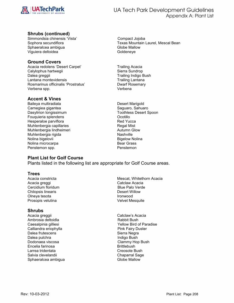
UA Tech Park Development Guidelines Appendix A: Plant List
Rev: 10-03-2012 Plant List: Page 208
Shrubs (continued) Simmondsia chinensis ‘Vista’ Compact Jojoba Sophora secundiflora Texas Mountain Laurel, Mescal Bean Sphaeralcea ambigua Globe Mallow Viguiera deltoidea Goldeneye
Ground Covers Acacia redolens ‘Desert Carpet’ Trailing Acacia Calylophus hartwegii Sierra Sundrop Dalea greggii Trailing Indigo Bush Lantana montevidensis Trailing Lantana Rosmarinus officinalis ‘Prostratus’ Dwarf Rosemary Verbena spp. Verbena Accent & Vines Baileya multiradiata Desert Marigold Carnegiea gigantea Saguaro, Sahuaro Dasylirion longissimum Toothless Desert Spoon Fouquieria splendens Ocotillo Hesperaloe parviflora Red Yucca Muhlenbergia capillaries Regal Mist Muhlenbergia lindheimeri Autumn Glow Muhlenbergia rigida Nashville Nolina bigelovii Bigelow Nolina Nolina microcarpa Bear Grass Penstemon spp. Penstemon Plant List for Golf Course Plants listed in the following list are appropriate for Golf Course areas. Trees Acacia constricta Mescat, Whitethorn Acacia Acacia greggi Catclaw Acacia Cercidium floridum Blue Palo Verde Chilopsis linearis Desert Willow Olneya tesota Ironwood Prosopis velutina Velvet Mesquite Shrubs Acacia greggii Catclaw’s Acacia Ambrosia deltoidla Rabbit Bush Caesalpinia gilliesi Yellow Bird of Paradise Calliandra eriophylla Pink Fairy Duster Dalea frutescens Sierra Negra Dalea pulchra Indigo Bush Dodonaea viscosa Clammy Hop Bush Encelia farinosa Brittlebush Larrea tridentata Creosote Bush Salvia clevelandii Chaparral Sage Sphaeralcea ambigua Globe Mallow

UA Tech Park Development Guidelines Appendix A: Plant Catalogue
Rev: 10-03-2012 Plant List: Page 209
Shrubs (continued) Viguiera deltoidea Goldeneye Ground Covers Acacia redolens ‘Desert Carpet’ Trailing Acacia Calylophus hartwegii Sierra Sundrop Lantana montevidensis Trailing Lantana Accent & Vines Baileya multiradiata Desert Marigold Carnegiea gigantea Saguaro, Sahuaro Dasylirion longissimum Toothless Desert Spoon Dasylirion texanum Green Desert Spoon Dasylirion wheeleri Desert Spoon, Sotol Fouquieria splendens Ocotillo Hesperaloe parviflora Red Yucca Muhlenbergia capillaries Regal Mist Muhlenbergia lindheimeri Autumn Glow Muhlenbergia rigida Nashville Nolina bigelovii Bigelow Nolina Nolina microcarpa Bear Grass Oenothera berlandieri Mexican Evening Primrose Oenothera caespitosa White Evening Primrose Opuntia acanthocarpa Buckhorn Cholla Opuntia basilaris Beavertail Prickly Pear Opuntia phaeacantha discata Engelmann Prickly Pear Opuntia violacea santa-rita Purple Prickly Pear Penstemon spp. Penstemon Accent & Vines Psilostrophe cooperi Paper Flower Yucca spp. Yucca

UA Tech Park Development Guidelines Appendix A: Plant Catalogue
Rev: 10-03-2012 Plant List: Page 210
UA Tech Park Plant Catalogue This plant catalogue includes all the trees, shrubs, ground covers, accent plants and vines listed in Appendix A: Plant Palettes of this document and permitted in the UA Tech Park. Refer to Appendix A to locate the plant list for the corresponding land use designation and use this catalogue as a guide for easy identification of plant specimens.

UA Tech Park Development Guidelines Appendix A: Plant Catalogue
Rev: 10-03-2012 Plant List: Page 211
Trees Mature Plant Scientific Name Common Name Detail
Acacia aneura Mulga
Acacia constricta
Mescat, Whitethorn Acacia
Acacia greggi
Catclaw Acacia
Acacia smallii Southwestern Sweet Acacia
Acacia stenophylla Shoestring Acacia

UA Tech Park Development Guidelines Appendix A: Plant Catalogue
Rev: 10-03-2012 Plant List: Page 212
Trees (Continued) Mature Plant Scientific Name Common Name Detail
Bauhinia forficate Orchid Tree
Bauhinia lunarioides Pink Orchid Tree
Brachychiton populneus Bottle Tree
Carya illinoinensis (many cultivars)
Pecan (many cultivars)
Callistemon citrinus
Lemon Bottlebrush
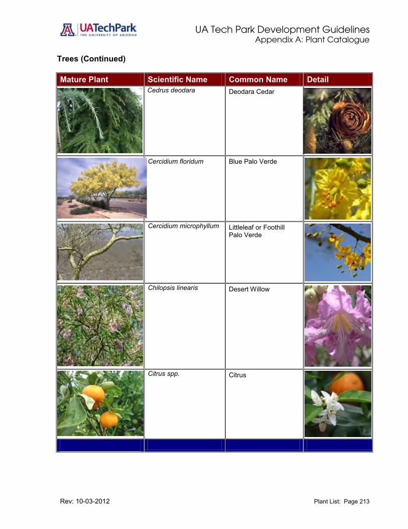
UA Tech Park Development Guidelines Appendix A: Plant Catalogue
Rev: 10-03-2012 Plant List: Page 213
Trees (Continued) Mature Plant Scientific Name Common Name Detail
Cedrus deodara
Deodara Cedar
Cercidium floridum Blue Palo Verde
Cercidium microphyllum
Littleleaf or Foothill Palo Verde
Chilopsis linearis
Desert Willow
Citrus spp. Citrus
Citrus

UA Tech Park Development Guidelines Appendix A: Plant Catalogue
Rev: 10-03-2012 Plant List: Page 214
Trees (Continued) Mature Plant Scientific Name Common Name Detail
Cupressus arizonica
Rough Barked Arizona Cypress
Cupressus glabra Smooth Barked Arizona Cypress Smooth Barked Arizona Cypress
Cupressus sempervirens
Italian Cypress
Eucalyptus microtheca
Coolibah
Eucalyptus papuana
Ghost Gum
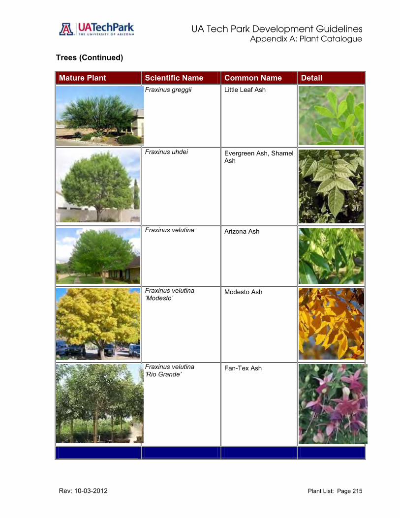
UA Tech Park Development Guidelines Appendix A: Plant Catalogue
Rev: 10-03-2012 Plant List: Page 215
Trees (Continued) Mature Plant Scientific Name Common Name Detail
Fraxinus greggii
Little Leaf Ash
Fraxinus uhdei
Evergreen Ash, Shamel Ash
Fraxinus velutina
Arizona Ash
Fraxinus velutina ‘Modesto’
Modesto Ash
Fraxinus velutina ‘Rio Grande’
Fan-Tex Ash

UA Tech Park Development Guidelines Appendix A: Plant Catalogue
Rev: 10-03-2012 Plant List: Page 216
Trees (Continued) Mature Plant Scientific Name Common Name Detail
Juglans major
Arizona Black Walnut
Magnolia grandiflora Southern Magnolia Magnolia
Olneya tesota
Ironwood
Pinus canariensis Canary Island Pine
Pinus halepensis
Aleppo Pine

UA Tech Park Development Guidelines Appendix A: Plant Catalogue
Rev: 10-03-2012 Plant List: Page 217
Trees (Continued) Mature Plant Scientific Name Common Name Detail
Pistacia atlantica
Mr. Atlas Pistache
Pistacia chinensis
Chinese Pistache
Pistacia lentiscus
Evergreen Pistache
Phoenix canariensis Canary Island Date Palm
Phoenix dactylifera Date Palm

UA Tech Park Development Guidelines Appendix A: Plant Catalogue
Rev: 10-03-2012 Plant List: Page 218
Trees (Continued) Mature Plant Scientific Name Common Name Detail
Pithecellobium flexicaule
Texas Ebony
Platanus racemosa
California Sycamore or Plane Tree
Podocarpus macrophyllus Yew Pine
Yew Pine
Prosopis alba Argentine Mesquite
Prosopis chilensis Chilean Mesquite

UA Tech Park Development Guidelines Appendix A: Plant Catalogue
Rev: 10-03-2012 Plant List: Page 219
Trees (Continued) Mature Plant Scientific Name Common Name Detail
Prosopis glandulosa glandulosa
Honey or Texas Mesquite
Prosipis So. Am. hybrid Hybrid South American Mesquite
Prosopis velutina Velvet Mesquite
Quercus virginiana ‘Heritage’
Heritage Live Oak
Trachycarpus fortunei Windmill Palm

UA Tech Park Development Guidelines Appendix A: Plant Catalogue
Rev: 10-03-2012 Plant List: Page 220
Trees (Continued) Mature Plant Scientific Name Common Name Detail
Ulmus parvifolia Chinese Elm
Vitex agnus-castus Monk’s Pepper
Washingtonia filifer California Fan Palm
Washingtonia robusta Mexican Fan Palm

UA Tech Park Development Guidelines Appendix A: Plant Catalogue
Rev: 10-03-2012 Plant List: Page 221
Shrubs Mature Plant Scientific Name Common Name Detail
Acacia craspedocarpa Leatherleaf Acacia
Ambrosia deltoidla
Rabbit Bush
Aquilegia chrysantha Golden Columbine
Bougainvillea spp. Bougainvillea, many varieties
Buddleia marrubiifolia Wooly Butterfly Bush

UA Tech Park Development Guidelines Appendix A: Plant Catalogue
Rev: 10-03-2012 Plant List: Page 222
Shrubs (Continued) Mature Plant Scientific Name Common Name Detail
Caesalpinia giliesii Yellow Bird of Paradise
Caesalpinia pulcherrima Red Bird of Paradise
Calliandra californica Red Baja Fairy Duster
Calliandra eriophylla Pink Fairy Duster
Callistemon citrinus Lemon Bottlebrush
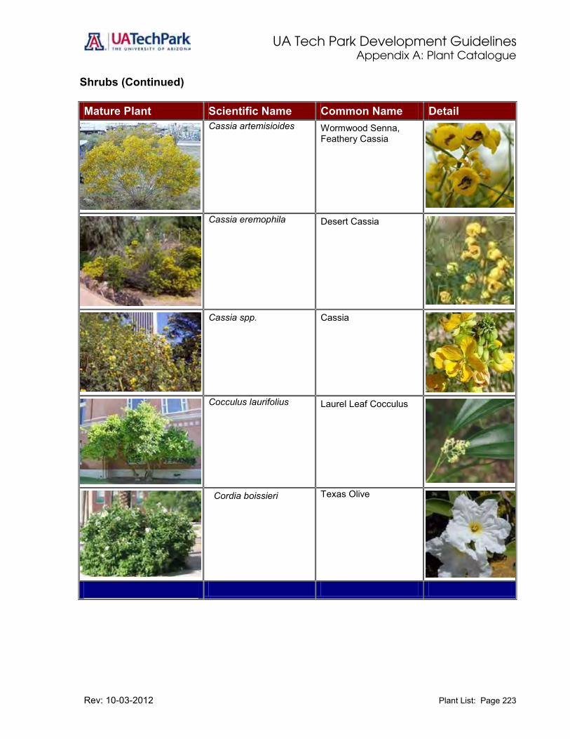
UA Tech Park Development Guidelines Appendix A: Plant Catalogue
Rev: 10-03-2012 Plant List: Page 223
Shrubs (Continued) Mature Plant Scientific Name Common Name Detail
Cassia artemisioides
Wormwood Senna, Feathery Cassia
Cassia eremophila
Desert Cassia
Cassia spp. Cassia
Cocculus laurifolius
Laurel Leaf Cocculus
Cordia boissieri Texas Olive

UA Tech Park Development Guidelines Appendix A: Plant Catalogue
Rev: 10-03-2012 Plant List: Page 224
Shrubs (Continued) Mature Plant Scientific Name Common Name Detail
Dalea bicolor v. bicolor Monterrey Blue
Dalea frutescens Sierra Negra
Dalea pulchra Indigo Bush
Dodonaea viscose
Hop Bush
Dodonaea viscosa ‘Purpurea’
Purple Hop Bush
Encelia farinose
Brittlebush

UA Tech Park Development Guidelines Appendix A: Plant Catalogue
Rev: 10-03-2012 Plant List: Page 225
Shrubs (Continued) Mature Plant Scientific Name Common Name Detail
Eremophila spp. Emu Bush
Fatshedera lizei
Fatshedera
Fatsia japonica
Japanese Aralia
Feijoa sellowiana Pineapple Guava
Gardenia jasminoides spp.
Gardenia

UA Tech Park Development Guidelines Appendix A: Plant Catalogue
Rev: 10-03-2012 Plant List: Page 226
Shrubs (Continued) Mature Plant Scientific Name Common Name Detail
Juniperus chinensis spp.
Juniper
Justicia spicigera Mexican Honeysuckle
Lagerstroemia indica (many cultivars)
Crape Myrtle (many cultivars)
Lantana camera (many cultivars)
Bush Lantana (many cultivars)
Larrea tridentate
Creosote Bush

UA Tech Park Development Guidelines Appendix A: Plant Catalogue
Rev: 10-03-2012 Plant List: Page 227
Shrubs (Continued) Mature Plant Scientific Name Common Name Detail
Leucophyllum frutescens spp.
Texas Ranger
Leucophyllum frutescens ‘Compactum’
Texas Ranger Compact
Myrtus communis True Myrtle, Roman Myrtle
Myrtus communis ‘Compacta’
Dwarf Myrtle
Nandina domestica Heavenly Bamboo, Nandina

UA Tech Park Development Guidelines Appendix A: Plant Catalogue
Rev: 10-03-2012 Plant List: Page 228
Shrubs (Continued) Mature Plant Scientific Name Common Name Detail
Laurus nobilis
True Bay, Grecian Laurel
Nandina domestica ’Compacta’
Compact Nandina
Nandina domestica ‘Nana’
Dwarf Nandina
Nerium oleander Oleander
Pennisetum setaceum ‘Cupreum’
Purple Fountain Grass
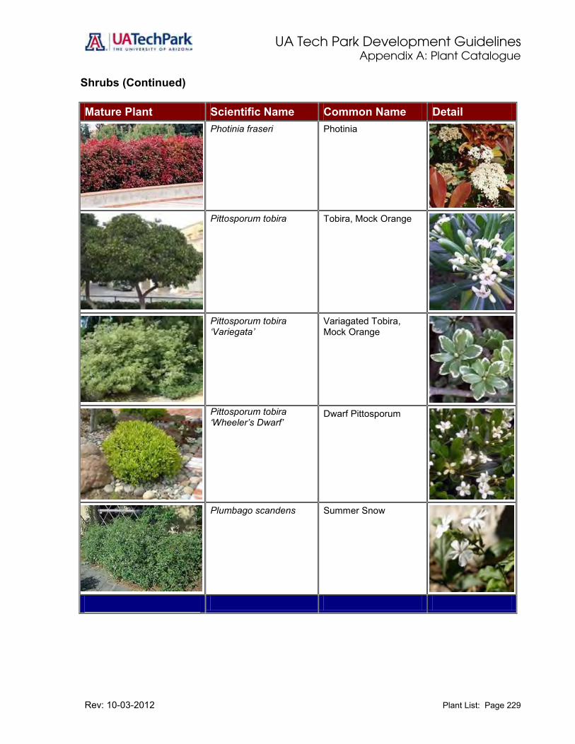
UA Tech Park Development Guidelines Appendix A: Plant Catalogue
Rev: 10-03-2012 Plant List: Page 229
Shrubs (Continued) Mature Plant Scientific Name Common Name Detail
Photinia fraseri Photinia
Pittosporum tobira Tobira, Mock Orange
Pittosporum tobira ‘Variegata’
Variagated Tobira, Mock Orange
Pittosporum tobira ‘Wheeler’s Dwarf’
Dwarf Pittosporum
Plumbago scandens Summer Snow

UA Tech Park Development Guidelines Appendix A: Plant Catalogue
Rev: 10-03-2012 Plant List: Page 230
Shrubs (Continued) Mature Plant Scientific Name Common Name Detail
Podocarpus macrophyllus
Yew Pine
Rosa banksiae Lady Banks’ Rose
Rosmarinus officinalis Rosemary
Rhus ovata Sugar Bush
Ruellia brittoniana Blue Ruellia

UA Tech Park Development Guidelines Appendix A: Plant Catalogue
Rev: 10-03-2012 Plant List: Page 231
Shrubs (Continued) Mature Plant Scientific Name Common Name Detail
Ruellia peninsularis Desert Ruellia
Salvia chamaedroyides Mexican Blue Sage
Salvia clevelandii Chaparral Sage
Salvia greggii Red Sage
Salvia leucantha Mexican Bush Sage
Simmondsia chinensis Jojoba
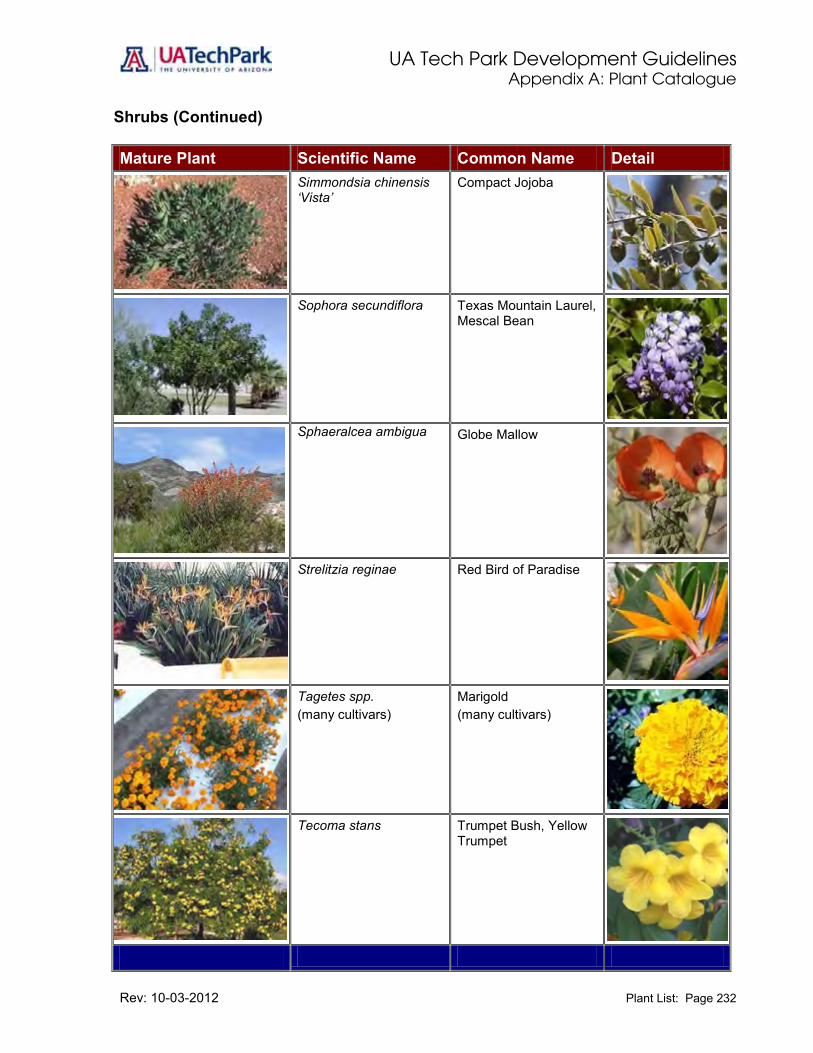
UA Tech Park Development Guidelines Appendix A: Plant Catalogue
Rev: 10-03-2012 Plant List: Page 232
Shrubs (Continued) Mature Plant Scientific Name Common Name Detail
Simmondsia chinensis ‘Vista’
Compact Jojoba
Sophora secundiflora Texas Mountain Laurel, Mescal Bean
Sphaeralcea ambigua
Globe Mallow
Strelitzia reginae Red Bird of Paradise
Tagetes spp. (many cultivars)
Marigold (many cultivars)
Tecoma stans Trumpet Bush, Yellow Trumpet

UA Tech Park Development Guidelines Appendix A: Plant Catalogue
Rev: 10-03-2012 Plant List: Page 233
Shrubs (Continued) Mature Plant Scientific Name Common Name Detail
Tecomaria capensis Cape Honeysuckle
Vauquelinia californica Arizona Rosewood
Viguiera deltoidea
Goldeneye
Xylosma congestum Xylosma
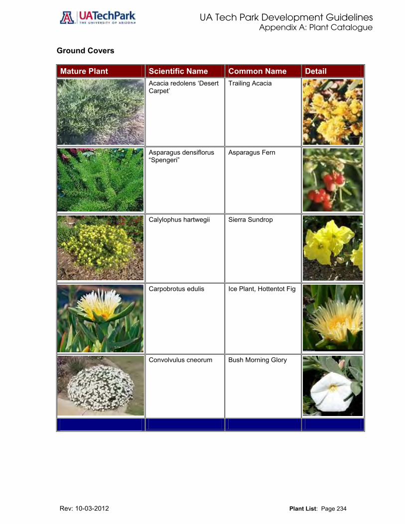
UA Tech Park Development Guidelines Appendix A: Plant Catalogue
Rev: 10-03-2012 Plant List: Page 234
Ground Covers Mature Plant Scientific Name Common Name Detail
Acacia redolens ‘Desert Carpet’
Trailing Acacia
Asparagus densiflorus “Spengeri”
Asparagus Fern
Calylophus hartwegii Sierra Sundrop
Carpobrotus edulis Ice Plant, Hottentot Fig
Convolvulus cneorum Bush Morning Glory

UA Tech Park Development Guidelines Appendix A: Plant Catalogue
Rev: 10-03-2012 Plant List: Page 235
Ground Covers (Continued) Mature Plant Scientific Name Common Name Detail
Dalea greggii Trailing Indigo Bush
Gelsemium sempervirens
Carolina Jessamine
Lantana montevidensis Trailing Lantana
Liriope muscari spp. Lily Turf
Myoporum parvifolium Prostrate Myoporum

UA Tech Park Development Guidelines Appendix A: Plant Catalogue
Rev: 10-03-2012 Plant List: Page 236
Ground Covers (Continued) Mature Plant Scientific Name Common Name Detail
Ophiopogon japonicus Mondo Grass
Rosmarinus officinalis ‘Prostratus’
Dwarf Rosemary
Teucrium chamaedrys ‘Prostratum’
Prostrate Germander
Trachelospermum asiaticum
Asiatic Jasmine
Trachelospermum jasminoides
Star Jasmine

UA Tech Park Development Guidelines Appendix A: Plant Catalogue
Rev: 10-03-2012 Plant List: Page 237
Ground Covers (Continued) Mature Plant Scientific Name Common Name Detail
Verbena spp. Verbena
Vinca major Periwinkle
Vinca major ‘Variegata’ Variegated Periwinkle

UA Tech Park Development Guidelines Appendix A: Plant Catalogue
Rev: 10-03-2012 Plant List: Page 238
Accent and Vines Mature Plant Scientific Name Common Name Detail
Agave gemniflora Twin-flowered Agave
Agave murpheyi Murphy Agave
Agave victoriae-reginae Queen Victoria Agave
Agave vilmoriniana Octopus Agave
Aloe barbadensis Aloe Vera, Medicinal Aloe
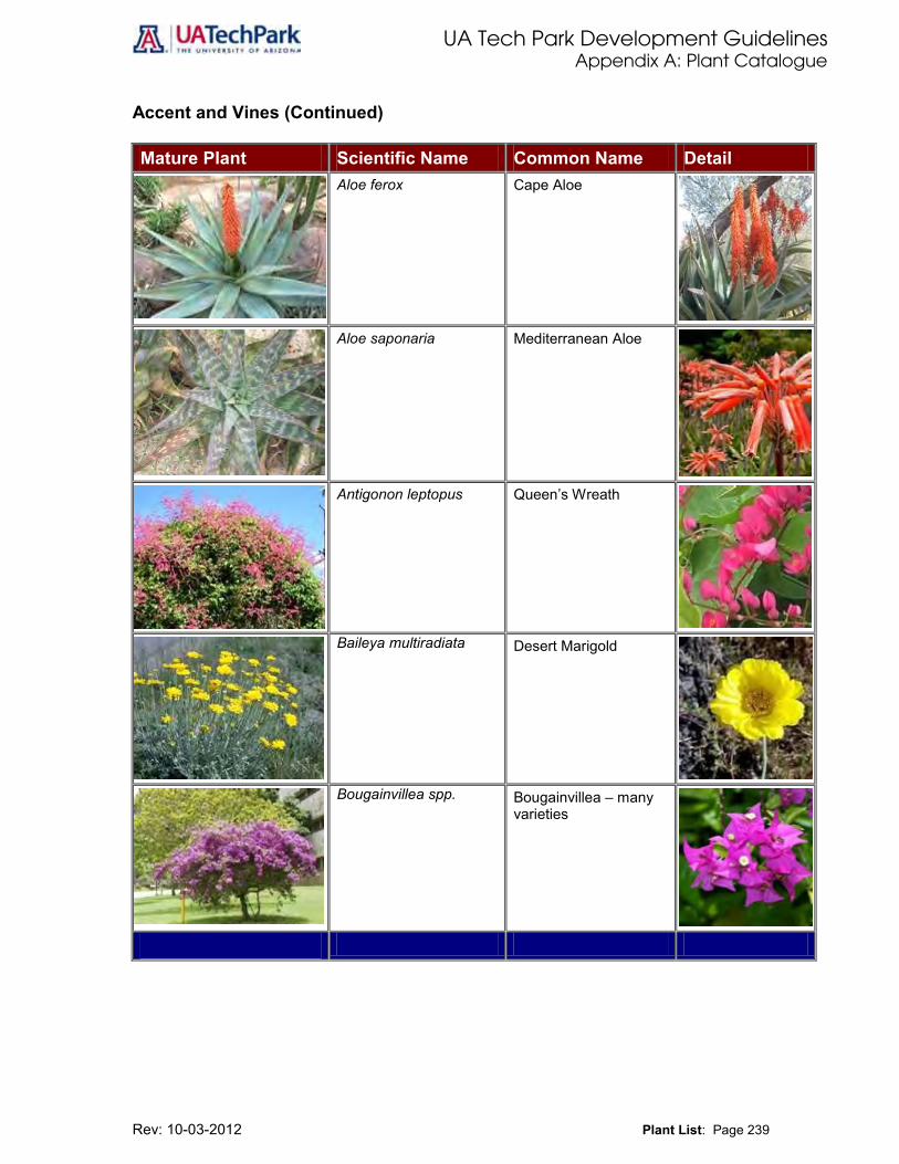
UA Tech Park Development Guidelines Appendix A: Plant Catalogue
Rev: 10-03-2012 Plant List: Page 239
Accent and Vines (Continued) Mature Plant Scientific Name Common Name Detail
Aloe ferox Cape Aloe
Aloe saponaria Mediterranean Aloe
Antigonon leptopus Queen’s Wreath
Baileya multiradiata
Desert Marigold
Bougainvillea spp.
Bougainvillea – many varieties
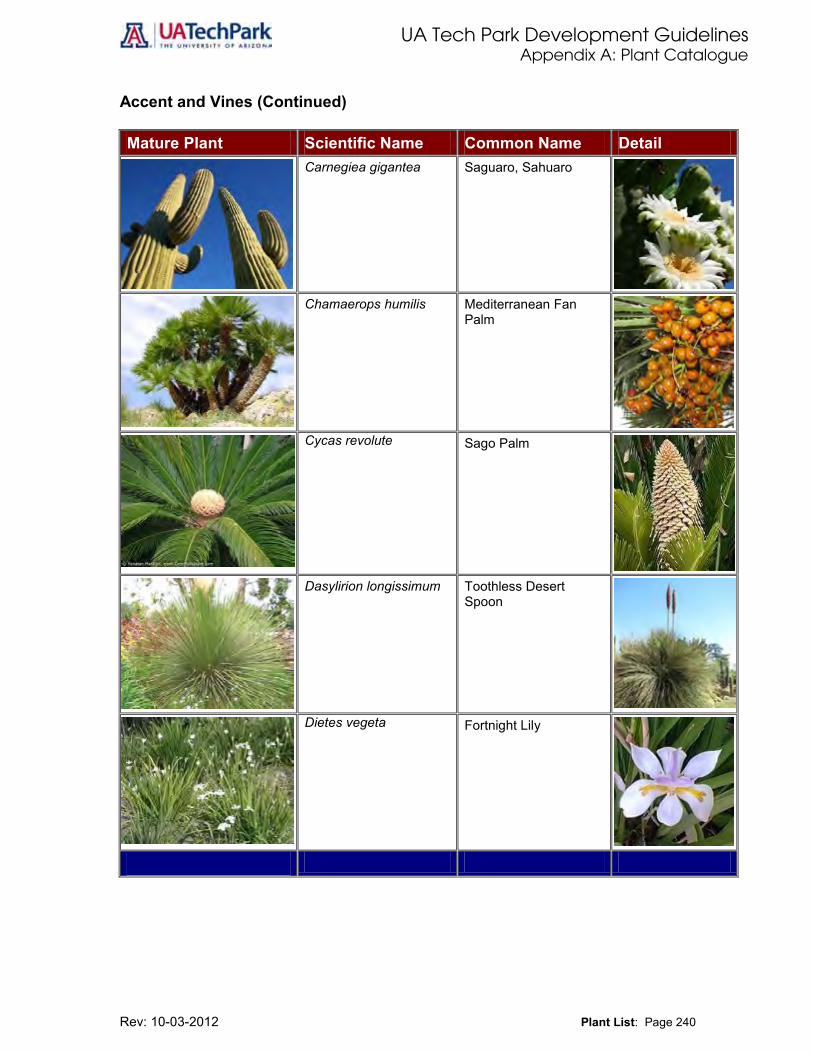
UA Tech Park Development Guidelines Appendix A: Plant Catalogue
Rev: 10-03-2012 Plant List: Page 240
Accent and Vines (Continued) Mature Plant Scientific Name Common Name Detail
Carnegiea gigantea Saguaro, Sahuaro
Chamaerops humilis Mediterranean Fan Palm
Cycas revolute
Sago Palm
Dasylirion longissimum Toothless Desert Spoon
Dietes vegeta
Fortnight Lily

UA Tech Park Development Guidelines Appendix A: Plant Catalogue
Rev: 10-03-2012 Plant List: Page 241
Accent and Vines (Continued) Mature Plant Scientific Name Common Name Detail
Dasylirion texanum Green Desert Spoon
Dasylirion wheeleri Desert Spoon, Sotol
Echinocactus grusonii Golden Barrel
Euphorbia biglandulosa Gopher Plant
Ficus pumila Creeping Fig
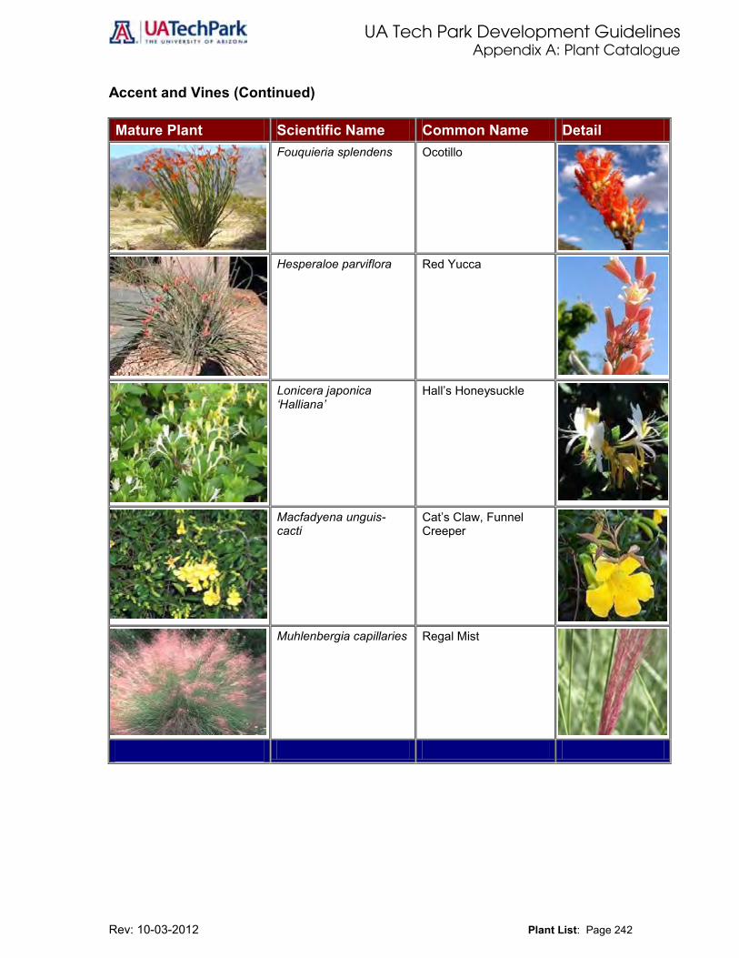
UA Tech Park Development Guidelines Appendix A: Plant Catalogue
Rev: 10-03-2012 Plant List: Page 242
Accent and Vines (Continued) Mature Plant Scientific Name Common Name Detail
Fouquieria splendens Ocotillo
Hesperaloe parviflora Red Yucca
Lonicera japonica ‘Halliana’
Hall’s Honeysuckle
Macfadyena unguis-cacti
Cat’s Claw, Funnel Creeper
Muhlenbergia capillaries Regal Mist

UA Tech Park Development Guidelines Appendix A: Plant Catalogue
Rev: 10-03-2012 Plant List: Page 243
Accent and Vines (Continued) Mature Plant Scientific Name Common Name Detail
Muhlenbergia lindheimeri
Autumn Glow
Muhlenbergia rigida Nashville
Nolina bigelovii Bigelow Nolina
Nolina microcarpa Bear Grass
Oenothera berlandieri Mexican Evening Primrose

UA Tech Park Development Guidelines Appendix A: Plant Catalogue
Rev: 10-03-2012 Plant List: Page 244
Accent and Vines (Continued) Mature Plant Scientific Name Common Name Detail
Oenothera caespitosa White Evening Primrose
Opuntia basilaris Beavertail Prickly Pear
Opuntia ficus-indica Tuna Cactus, Spineless Cactus
Opuntia phaeacantha discata
Engelmann Prickly Pear
Opuntia violacea santa-rita
Purple Prickly Pear

UA Tech Park Development Guidelines Appendix A: Plant Catalogue
Rev: 10-03-2012 Plant List: Page 245
Accent and Vines (Continued) Mature Plant Scientific Name Common Name Detail
Osteospermum fruticosum
White Trailing African Daisy
Pennisetum setaceum ‘Cupreum’
Purple Fountain Grass
Penstemon spp. Penstemon
Philodendron selloum Philodendron, Selloum
Psilostrophe cooperi
Paper Flower

UA Tech Park Development Guidelines Appendix A: Plant Catalogue
Rev: 10-03-2012 Plant List: Page 246
Accent and Vines (Continued) Mature Plant Scientific Name Common Name Detail
Psilostrophe cooperi
Paper Flower
Rosa banksiae
Lady Banks’ Rose
Verbena peruviana
Peruvian Verbena
Vinca major
Periwinkle

UA Tech Park Development Guidelines Appendix A: Plant Catalogue
Rev: 10-03-2012 Plant List: Page 247
Accent and Vines (Continued) Mature Plant Scientific Name Common Name Detail
Vinca major ‘Variegata’
Variegated Periwinkle
Yucca spp. Yucca

UA Tech Park Development Guidelines Appendix B
Rev: 10-03-2012 Compliance Cross-Reference Matrix for Designated Land Uses: Page 248
Table 17: Compliance Cross-Reference Matrix for Designated Land Uses
Land Uses
Development Precepts/Policy Direction
General Guidelines and Development Standards
Specific Development Guidelines
Use Location with Respect to Davis-Monthan AFB ADC
Research Park UA Tech Park Master Plan volume
Section IV: General Guidelines Development Guidelines volume
Section VI: Specific Development Guidelines Development Guidelines Volume 0-30,000 ft. ADC
Assembly/Manufacturing UA Tech Park Master Plan volume
Section IV: General Guidelines Development Guidelines volume
Section VI: Specific Development Guidelines Development Guidelines Volume 0-30,000 ft. ADC
Business Development UA Tech Park Master Plan volume
Section IV: General Guidelines Development Guidelines volume
Section VI: Specific Development Guidelines Development Guidelines Volume 30,000-50,000 ft. ADC
Commercial/Hospitality UA Tech Park Master Plan volume
Section IV: General Guidelines Development Guidelines volume
Section VI: Specific Development Guidelines Development Guidelines Volume Outside of the ADC
Commercial UA Tech Park Master Plan volume
Section IV: General Guidelines Development Guidelines volume
Section VI: Specific Development Guidelines Development Guidelines Volume Outside of the ADC
Residential UA Tech Park Master Plan volume
Section IV: General Guidelines Development Guidelines volume
Section V: General Development Guidelines (Residential Development) Development Guidelines volume Outside of the ADC
Multifunctional Open Space Corridor
UA Tech Park Master Plan volume
Section IV: General Guidelines Development Guidelines volume
Section VI: Specific Development Guidelines Development Guidelines Volume 0-30,000 ft. ADC
Golf Course UA Tech Park Master Plan volume
Section IV: General Guidelines Development Guidelines volume
Section VI: Specific Development Guidelines Development Guidelines Volume 0-30,000 ft. ADC
Signature Entry Section IV: General Guidelines Development Guidelines volume
Not Applicable 30,000-50,000 ft. ADC (Rita Road) and outside of ADC (Kolb Road)
Davis-Monthan AFB Dedicated Open Space Corridor
UA Tech Park Master Plan volume
Section IV: General Guidelines Development Guidelines volume
Section VI: Specific Development Guidelines Development Guidelines Volume 0-30,000 ft. ADC
UA Solar Zone Overlay UA Tech Park Master Plan volume
Section IV: General Guidelines Development Guidelines volume
Not Applicable 0-30,000 ft. ADC
UA Tech Park Center Overlay Zone
UA Tech Park Master Plan volume
Section IV: General Guidelines Development Guidelines volume
Section VI: Specific Development Guidelines Development Guidelines Volume
Outside of the ADC/ 0-30,000 ft. ADC
UA Tech Park Plaza Overlay Zone
UA Tech Park Master Plan volume
Section IV: General Guidelines Development Guidelines volume
Section VI: Specific Development Guidelines Development Guidelines Volume
Outside of the ADC/ 0-30,000 ft. ADC
Low-Intensity Overlay Zone UA Tech Park Master Plan volume
Section IV: General Guidelines Development Guidelines volume
Section VI: Specific Development Guidelines Development Guidelines Volume 0-30,000 ft. ADC
UA Tech Park Development Guidelines Appendix C
Rev: 10-03-2012 Definitions: Page 249 249Definitions: Page 249
Appendix C
Definitions – A Abutting. Having a common boundary. Parcels or lots having only a common corner are not considered abutting.
Accessory Use or Structure. A use or structure subordinate to the principal use or building on a lot and serving a purpose customarily incidental to the use of the principal building, provided any such structure is built with or after the construction of the principal building.
Acre. Forty-three thousand five-hundred sixty (43,560) square feet.
ADC. Same as Approach/Departure Corridor.
Adjacent. Two (2) or more parcels or lots sharing a common boundary or separated by an alley or other right-of-way twenty (20) feet or less in width. Parcels or lots having only a common corner are considered adjacent.
Adjoining. Same as abutting.
ADOT. Same as Arizona Department of Transportation.
Aggregate Acre. The total acreage of gross lot area within the Tech Park owned and operated by the University of Arizona.
Aggregate Employee Density. The permitted number of employees per Aggregate Acre of gross lot area. Within the 0-30,000 ft. ADC, the Aggregate Employee Density permitted is 25 persons per Aggregate Acre of gross lot area.
Alley. A public way primarily for placement of utilities, refuse collection, or similar public services. Also a rear driveway providing access to a residential unit having rear garages.
Apartment Building. Same as multi-family residential development.
Approach/Departure Corridor (ADC). Davis-Monthan Air Force Base Approach/Departure Corridor as defined in the Arizona Statutes and in the Davis-Monthan Air Force Base/Tucson/Pima County Joint Land Use Study (JLUS)
Definitions – B Barrier-Free Accessibility. Functional access for semi-ambulatory and non-ambulatory persons, from a street or parking space to, into, and through a building.
Barrier-Free/Handicapped Parking. Parking standards and provisions meeting all American Disability Act (ADA) requirements.
Bicycle Parking Facility. A structure that provides temporary placement for bicycles.
Bicycle Parking Space. An area designated within a Bicycle Parking Facility for the use of an individual bicycle.
Buildable Area. The area of a lot where a building can be placed after setbacks from property lines, streets, buildings, or any other point identified in these Development Guidelines are deducted.
Building Coverage. The total amount of a lot or parcel allowed to be covered by buildings (excluding landscaped or recreation areas, covered patios, driveways, parking, etc.) at the individual lot or parcel level divided by the total gross lot area, not to exceed 50% of the lot

UA Tech Park Development Guidelines Appendix C
Rev: 10-03-2012 Definitions: Page 250 250Definitions: Page 250
gross area unless specified otherwise in Section IV (Table 23) of these Development Guidelines.
Building Footprint. The ground area within the outside edges of the exterior of a building at design grade.
Building Height. The vertical dimension of a building, measured from grade.
Building Setback. The right angle distance from a specified point to the closest point of any building wall.
Definitions – C Canopy Tree. A woody plant, other than a palm tree, with a mature crown diameter of at least fifteen (15) feet and having a trunk that, at maturity, is kept clear of leaves and branches at least six (6) feet above grade.
Communication, Wireless Facilities. A commercial facility designed and operated for the transmission and reception of signals to and from multiple transmitter locations to multiple reception locations.
Conservation Easement. An easement delineating an area that will be kept in its natural state in perpetuity.
Contiguous. Same as abutting.
Definitions – D Design Review Committee. The UA Office of University Research Parks Design Review Committee reviews all development plans for compliance with The Tech Park Master Plan and the Development Guidelines. The Design Review Committee reviews and approves all new development occurring at the UA Tech Park and at the UA BioPark.
Density. The number of residential units permitted per acre of developable area within a residential site as provided in Tables 6 and 7 of these Development Guidelines.
Development Guidelines or The University of Arizona Science and Technology Park Development Guidelines. The volume of the Tech Park Guide establishing criteria that communicates the standard of development and level of quality expected throughout the Tech Park, and providing specific guidance for new development.
Development Plan. A drawing of a project site that provides detailed information which shows how a proposed project will be developed in compliance with The Tech Park Master Plan, and the Development.
Drought-Tolerant Vegetation. Low-water-use plants which, after they are established, can survive within the Sonoran Desert climate with little or no supplemental watering.
Definitions – E Employment Center. A grouping of commercial, institutional, office, and/or industrial of such scale and in such proximity to each other that enables and encourages employees to use alternate modes of travel both to and from work and during daily activities (e.g., office, service, retail, restaurant, banking).
Employee Density. The permitted number of employees per acre of gross lot for parcels located within the 0-30,000 ft. ADC that is owned and operated by an entity other than the University of Arizona.
Entrance Drive. A road providing access to individual building drop-off and parking areas.

UA Tech Park Development Guidelines Appendix C
Rev: 10-03-2012 Definitions: Page 251 251Definitions: Page 251
Definitions – F FAA. Same as Federal Aviation Administration.
Floor Area. Same as Gross Floor Area.
Frontage. The length of a lot line which abuts a street right-of-way.
Definitions – G GFA. Same as Gross Floor Area.
GBSA. Same as Gross Building Square Footage.
Gross Floor Area. The sum of the horizontal areas of all floors of all buildings, measured from the exterior faces of the exterior walls or from the centerline of walls separating two (2) buildings and includes elevator shafts and the stairwells at each story; floor space with structural headroom of six (6) feet and six (6) inches or more used for mechanical equipment; penthouses; attic space; interior balconies; mezzanines; and service bays but does not include any interior space used for parking, loading, or loading space that is incidental to the principal use.
Gross Building Square Footage. The sum of all areas on all floors of a building included within the outside faces of the its exterior walls, including floor penetration areas, however insignificant, for circulation and shaft areas that connect one floor to another.
a) Basis for Measurement: Gross area is computed by physically measuring or scaling measurements from the outside faces of exterior walls, disregarding cornices, pilasters, buttresses, etc., which extend beyond the wall faces. Exclude areas having less than a six-foot, six-inch clear ceiling height unless the criteria of a separate structure are met.
b) Description: In addition to all the internal floored spaces covered above, gross area should include the following: excavated basement areas; mezzanines, penthouses, and attics; garages; enclosed porches, inner or outer balconies whether walled or not, if they are utilized for operational functions; and corridors whether walled or not, provided they are within the outside face lines of the building, to the extent of the roof drip line. The footprints of stairways, elevator shafts, and ducts (examples of building infrastructure) are to be counted as gross area on each floor through which they pass.
c) Limitations: Exclude open areas such as parking lots, playing fields, courts, and light wells, or portions of upper floors eliminated by rooms or lobbies that rise above single-floor ceiling height.
d) Exception: Include top, unroofed floor of parking structures where parking is available.
Definitions – H Heliport. A place designated for the landing and take-off of helicopters, including its buildings and facilities.
Definitions – I Information Display System. Technology used to display information on screens for communication. Information Kiosk. Same as Information Display System. Internal Drive. A road shared by more than one user for access to building parcels.
UA Tech Park Development Guidelines Appendix C
Rev: 10-03-2012 Definitions: Page 252 252Definitions: Page 252
Definitions – J Julian Wash. The main east-west wash traversing the Tech Park.
Definitions – K Kiosk. Same as Information Kiosk.
Definitions – L Land Use. A description of the existing or proposed occupancy or utilization of land as provided in The Tech Park Master Plan, which includes the principal use and accessory uses.
Landscape Materials. Any materials used for the purpose of landscape improvement and/or screening which may include, but are not limited to, the following: trees; shrubs; vegetative ground covers; turf; vines; and any plant material listed in Appendix A of these Development Guidelines; walkways; berms; stone or inert ground cover materials; sculptures; fountains; irrigation equipment; street furniture; outdoor accent lighting; fences; or walls.
Landscape Plan. A graphic representation of the development site indicating the location of all existing and proposed landscape improvements to be present on the site at the completion of the construction of the project submitted to the UA Office of University Research Parks Design Review Committee for review and approval.
Landscaping. An exterior improvement of a site in accordance with a UA Office of University Research Parks Design Review Committee approved landscape plan and landscape methods, materials, and maintenance.
Ldn (Day-Night Average Sound Level) Ldn values are expressed in decibels and represent an average noise level over a twenty-four (24) hour period for an average day of the year. For Davis-Monthan Air Force Base, Ldn values are calculated based on the Department of Defense Noise Map model which averages noise over the total flying days of the year.
Lot. A tract of land bounded on all sides by property lines, of sufficient size to meet minimum requirements, with legal access to a public or private street.
Lot Coverage. The total amount of impervious surface (building, parking, driveway, etc.) at the individual parcel level divided by the total gross lot area, not to exceed 50% of the total gross lot area unless specified otherwise in Section IV (Table 23) of these Development Guidelines.
Lot Line. Same as Property Line.
Definitions – M Mixed Use. A development on a site with two (2) or more principal land uses designed and developed as a single coordinated area utilizing common design elements or shared facilities. Mixed use development is appropriate in areas designated in the Tech Park Land Use Plan as Commercial/Hospitality and Business Development I, II, and III and within the Tech Park Center Overlay. Common design elements must comply with the following criteria:
a) Shared vehicular and pedestrian access and circulation is provided to the site.
b) Parking areas a common to all land uses on the site.
c) All common or shared facilities are legally documented for use by all land uses on site for the life of the project as a mixed use.
Multiple-Family Structure or Multi-family Structure. A building located on one (1) lot, containing two (2) or more dwelling units. Also known as multi-family structure and apartment building.
UA Tech Park Development Guidelines Appendix C
Rev: 10-03-2012 Definitions: Page 253 253Definitions: Page 253
Definitions – N
Native Vegetation. Plants indigenous to the site and to the areas contiguous to the site.
Natural Grade. The topographic configuration of land, graphically represented by contour lines, prior to any grading or other human disturbance.
Net Square Footage. The total usable square footage of a facility. That is, square footage that is measured from the inside wall surfaces. Included in this figure are non-assignable spaces such as mechanical rooms, toilets, corridors, etc.
Net Assignable Square Footage. The total assignable square footage of a facility, measured from the inside wall surfaces, not including non-assignable spaces such as mechanical rooms, toilets, corridors, etc. Definitions – O Off-Street. Located within property boundaries and not within a right-of-way, such as a street or alley.
On-Street. Located within a right-of-way, such as a street or alley.
Definitions – P Parcel. The same as “lot.” The term “parcel” generally describes a piece of property recorded as a division of land by a metes and bounds description and not as part of a subdivision plat. In a project where a division of land is proposed (e.g. within areas designated Residential in the Tech Park Land Use Plan) each proposed division will be considered a lot for the purpose of applying the requirements of these Development Guidelines.
Parking Area. Same as Vehicular Use Area.
Parking Area Access Lane(s) (PAAL. The area within a parking lot serving as a travel lane or lanes to provide individual access to parking spaces. Typical examples include Research and Development parking lots, apartment developments using common parking, and other places in which the primary or sole purpose is to provide access to a parking area, as opposed to providing access directly to property.
Parking Garage. Same as Parking Structure.
Parking Lot. Same as Vehicular Use Area.
Parking Stall. Same as Parking Space.
Parking Space. An area of floor space reserved for the parking of one (1) vehicle, motorcycle, or bicycle in accordance with space dimension provided in these Development Guidelines.
Parking Structure. A structure used for the parking of vehicles where parking is accommodated on one (1) or more levels.
Pedestrian Street. Pedestrian mall within the Tech Park Plaza intended to foster an inviting and convenient setting for pedestrian travel, provides connectivity to Research Development land uses and adjacent support services.
Perimeter Yard. A setback area to separate buildings from adjacent property or streets.
PL. Same and Property Line.
Primary Roads. The main east-west and north-south arterials providing access to and through the Tech Park. Minimum road right-of-way for primary roads is 120 feet and should be developed in accordance to Illustration 18 of these Development Guidelines.

UA Tech Park Development Guidelines Appendix C
Rev: 10-03-2012 Definitions: Page 254 254Definitions: Page 254
Private Street. A street not dedicated to the public.
Project. A development, consisting of one (1) or more contiguous lots, planned and constructed to function as a single entity, utilizing common or shared facilities, structures, parking, and vehicular, bicycle, and pedestrian access.
Project Area. The area including the developed portion of the Tech Park and encompassing a total of 324 acres.
Project Operating Agreement. The volume of the University of Arizona Tech Park Guide establishing the legal and operational structure for the delivery common services to the individual Occupants (tenants) and Common Area of the Project, which is the 345 area designated by statute as a “Research Park.”
Project Site. Same as Project.
Property Line. The lot line which defines the exterior limits or a lot.
Definitions – Q Definitions – R Revegetation. Establishment of plants at a density similar to what exists under similar topographic and soil conditions.
Right-of-Way. An area reserved for a public or private use, such as, but not limited to, street or alley right-of-way and utility easement.
Riparian. Land adjacent to washes and drainageways which is occupied by biotic communities differing in species and composition and/or density from surrounding upland due to an increase in moisture and different soil conditions.
Roadway. The paved portion of a street, excluding curbs. On an unpaved street, the roadway is the area set aside for motor vehicle traffic including construction trucks and machinery.
ROW. Same as Right-of-Way.
Definitions – S Screen. An opaque barrier designed and constructed to conceal areas used for storage, refuse, mechanical equipment, parking, or delivery service loading bays from street and public view or to buffer adjacent land uses.
Secondary Roads. Roads that feed off of Primary Roads and that provide access into individual development clusters. Minimum road right-of-way for secondary roads is 70 feet. Secondary roads should be developed in accordance to Illustration 13 of these Development Guidelines.
Service Drive. A road providing access to loading and waste pick-up areas.
Setback. The distance from a set point as defined in these Development Guidelines.
Signature Entry Boulevard. The Tech Park main entry boulevards located at the Kolb Road, Rita Road, and proposed I-10 interchange entrances to the Tech Park.
Signature Entry Feature. The Tech Park main gateways or entry features located at the Kolb Road and Rita Road entrances to the Tech Park.
Single-Family Dwelling. A building containing one (1) dwelling unit.
Single-Family Dwelling, Attached. A dwelling unit attached on an horizontal plane to one (1) or more dwelling units by structural elements common to the attached units. Each dwelling unit is located on its own individual lot or separated by a line denoting a separate ownership of each unit. The

UA Tech Park Development Guidelines Appendix C
Rev: 10-03-2012 Definitions: Page 255 255Definitions: Page 255
structural elements include common wall construction, roof, or other similar improvements. Elements such as trellises, beams, and patio walls are not included.
Single-Family Dwelling, Detached. A dwelling unit which is not attached to any other dwelling unit by any structural elements, surrounded by open space and located on its own separate lot.
Site. The 1,345-acre Tech Park, consisting of contiguous lots, not including dedicated public property, designated for development as a single master planned Tech Park exclusive of any abutting public right-of-way.
Site Coverage. The total amount of impervious surface (building, parking, driveways, etc.) permitted at the Tech Park, not to exceed 55% of the total Tech Park acreage.
Site Plan. Same as Development Plan.
Solar Access. Access to sunlight to protect active or passive solar energy systems from shadows blocking exposure to the sun during hours of high insolation, from 9:20 a.m. to 3:20 p.m. local time.
Stacking space. An area designated to accommodate vehicles waiting in line.
State. Same as State of Arizona.
Street. Any permanent public or private right-of-way, other than an alley or parking area access lane, set aside to accommodate vehicular parking lanes, parking lanes, bike lanes, pedestrian facilities such as sidewalks or walkways, utility areas, and other such design features, whether designated as a primary road, secondary road, internal drive, entrance drive, service drive, road, boulevard, avenue, lane, or place.
Street Hierarchy. The functional hierarchy to streets and drives in the Tech Park adopted as part of these Development Guidelines and expressed in the street design and landscape treatment along the street. The street categories are: primary roads, secondary roads, internal drives, entrance drives, service drives, and pedestrian street or mall.
Definitions – T Travel Lanes. The area within a paved roadway reserved for moving vehicular traffic.
Turf. An area of grass ground cover grown together in a thick mat permitted only in the golf course area.
Definitions – U Utilities, Off-Site. Off-site utility services provided by an entity other than the University of Arizona such as gas, water, electric, telephone, high speed internet, and cable television.
Utilities, On-Site. On-site utility services provided by the Tech Park, including, but not limited to: power plant; environmentally sensitive and closed-loop sewage and water treatment facilities; water supply; comprehensive utility management system, which controls cooling, water, refrigeration, and sewage treatment; central spine distributing electrical power, communications cable; and plumbing for heating and cooling, and domestic and de-ionized water.
Definitions – V Vehicular Use Area. Any area or structure used for the parking, storage, or standing of motor vehicles. The vehicular use area includes access drives, maneuvering areas, refuse collection locations, loading spaces, and any landscape amenity and/or screening within ten (10) feet of these areas.

UA Tech Park Development Guidelines Appendix C
Rev: 10-03-2012 Definitions: Page 256 256Definitions: Page 256
Visibility. Clear line of sight maintained along all streets and driveways not blocked from view by buildings, structures, walls, landscaping, or natural features to provide for the safety of motorists, pedestrians, and bicyclists.
Visibility Triangle or Minimum Sight Distance Triangle. Sight visibility triangles depend on the following factors: Type of intersection control, type of movement, lane configuration, design speed, approach grade and design vehicle. Minimum sight distance triangle requirements must conform to Pima County Subdivision and Development Street Standards.
Definitions – W Wireless Communication. Same as Communication, Wireless.
Definitions – X Xeriscape. A landscaping program designed to save water using the seven (7) principles listed below:
a) Water conserving design.
b) Low water use/drought-tolerant plants.
c) Reduction in turf.
d) Water harvesting techniques.
e) Appropriate irrigation methods.
f) Soil improvements and use of mulches.
g) Proper maintenance practices.
Definitions – Y Definitions – Z

UA Tech Park Development Guidelines Appendix D
Rev: 10-03-2012 Bibliography: Page 257
Appendix D
Bibliography City of Tucson General Plan, (2001) City of Tucson, Arizona
City of Tucson Land Use Code (2002) City of Tucson, Arizona
City of Tucson Development Standards (2000) City of Tucson, Arizona
Davis-Monthan Air Force Base Airfield Compatibility Study: Final Initial Site Analysis Report (April 2001) United States Corps of Engineers, Albuquerque, new Mexico, Davis-Monthan Air Force Base, The Planning Center/Carter Burgess, Associates.
Davis-Monthan Air Force Base General Plan (2002) Davis-Monthan Air Force Base, Tucson, Arizona
Flood Insurance Rate Map (FIRM) Pima County Arizona Unincorporated Areas (1983) Panel 2879 of 4700 Federal Emergency Management Agency (FEMA)
Landiscor, Aerial Flight Date January 2010
Pima County Comprehensive Plan (2001) Pima County, Arizona.
Pima County Comprehensive Plan: Rincon/Southeast Sub-region (2003) Pima County, Arizona
Pima County Land Development Code (Updated through September 2003) Pima County, Arizona
Pima County Land Information Systems (2012) Pima County, Arizona
Pima County Subdivision and Development Street Standards (2004) Pima County, Arizona
Existing Water Infrastructure GIS Layer, Tucson Water, November 2004
The Arizona Military Regional Compatibility Project: Davis-Monthan Air Force Base/Tucson/Pima County Joint Land Use Study, JLUS, (February 2004) Arizona Department of Commerce and United States Department of Defense
The Original Ribbon Rack Bicycle Parking Mounting Instructions Technical Specifications (2003) Ribbon Rack Corporation, Inc., a Division of Brandir International, Inc. New York.
The University of Arizona Comprehensive Campus Plan (2003) University of Arizona, Tucson, Arizona
The University of Arizona Comprehensive Campus Plan (1988) University of Arizona, Tucson, Arizona
The University of Arizona Science and Technology Park Canopy and Bike Rack Installation Plan, Paramount Architecture, Tucson, Arizona
The University of Arizona Science and Technology Park Development Framework Planning: Phase 1 Site and Facility Assessment (1997) NBBJ, Seattle, Washington