ubc technical guidelines general …technicalguidelines.ubc.ca/...word/...record_docs.docx · web...
TRANSCRIPT
RfT#201xxxxxxx SECTION 01 78 39Project No. <Insert #> PROJECT RECORD DOCUMENTS<Insert Project Title> PAGE 1 OF 20
CONTENTS
1.0 General
1.1 Description1.2 Use1.3 Related Sections
2.0 Submissions
2.1 Drawings
2.1.1 Types of Drawings 2.1.2 Format Requirements 2.1.3 List2.1.4 CAD Production2.1.5 AIA Layering
2.2 Specifications 2.2.1 Format Requirements 2.2.2 List
3.0 Survey Monument Information
4.0 Current AutoCAD Layers in Use
The University of British Columbia Date Technical Guidelines Updated: May 2018 Technical Guidelines Date Modified for Project No. <Insert #>:<Insert date>
RfT#201xxxxxxx SECTION 01 78 39Project No. <Insert #> PROJECT RECORD DOCUMENTS<Insert Project Title> PAGE 2 OF 20
1.0 GENERAL
1.1 DESCRIPTION
1.1.1 This section deals with the submission requirements of drawings and specifications.
1.2 USE
1.2.1 CAD drawings submitted to Infrastructure Development, Records Section are simplified to create key plans and typically contain basic architectural elements to represent the current status of a building or campus site features. The key plans are maintained and can be provided back to consultants for future projects. The key plans are also used for location and data source for the following services:
• CAFM drawings for Space Inventory – Room Use, Area and Allocation• Emergency Procedure Key plans• Door Identification – Campus Access and Security / Locksmiths• Facility Planning • Room Scheduling
1.3 RELATED SECTIONS
1.3.1 Section 01 77 00 Closeout Procedures1.3.2 Section 01 78 23 Operation and Maintenance Data1.3.3 Section 33 00 10 Underground Utilities Services1.3.4 Section 26 05 00 Electrical – General Requirements
2.0 SUBMISSIONS
2.1 DRAWINGS
2.1.1 TYPES OF DRAWINGS
.1 ISSUED FOR CONSTRUCTION
.1 These drawings have been updated to incorporate major design changes and approved room numbers before construction commences. If Building Permit Drawings have previously been submitted and no changes are required, the Building Permit Drawings can be resubmitted as “Issued for Construction”. The Certified Professional must submit a letter to UBC Infrastructure Development, Records, confirming that there have been no substantial changes from the Building Permit set of drawings.
.2 “Issued for Construction” drawings are NOT accepted as As-Built drawings.
.3 One (1) PDF and (1) set of architectural floorplans in AutoCAD format files to be submitted to the Infrastructure Development, Records Section prior to the start of construction. See: 2.1.2 Format Requirements.
The University of British Columbia Date Technical Guidelines Updated: May 2018 Technical Guidelines Date Modified for Project No. <Insert #>:<Insert date>
RfT#201xxxxxxx SECTION 01 78 39Project No. <Insert #> PROJECT RECORD DOCUMENTS<Insert Project Title> PAGE 3 OF 20
.2 RECORD DRAWINGS
.1 Buildings
.1 These drawings are issued for all building projects and represent the final installed configuration of what was actually built. Record drawings are prepared by the Consultant using information furnished by the Contractor or other field staff.
.2 Record drawings incorporate all changes made during the construction process including any and all clarifications, addenda and Change Orders. A statement attesting to this is required from the certifying professional, and is to be included with the record drawing submission.
.3 One (1) PDF and (1) AutoCAD format files to be submitted to Infrastructure Development, Records Section within 60 days of Substantial Performance. See: 2.1.2 Format Requirements. The PDF files shall be clear and legible. UBC reserves the right to request a paper copy of the drawings if necessary.
.2 Underground Utility Services
.1 These drawings are a true record of underground utilities which represent the final installed configuration of what was actually built. A record drawing incorporates all changes made during the construction process including an as-constructed survey and any and all clarifications, addenda and Change Orders.
.2 Record drawings are verified in detail by the Professional Engineer through reviewing the actual conditions of the completed project. Verification by the reviewing engineer may require frequent or continuous presence on site.
.3 Where applicable, all relevant improvement sizes, diameters, elevations, depths and material must be specified on the approved plans. The field surveyor must check them during and/or after construction. They are to be relevant to the UBC Datum and nearest official UBC monument.
.4 Rim and invert elevations, and all pipe material and lengths shall clearly be marked “Record” on the Record Drawings.
.5 Two (2) paper copies plus one (1) PDF and one (1) AutoCAD format files to be submitted to Infrastructure Development, Records Section within 60 days of Substantial Performance of the civil contract. See: 2.1.2 Format Requirements. See also: Division 33, Section 33 00 10 Underground Utilities Services.
.6 Certification of Record drawings for Underground Utility Services
Record drawings are to be signed and sealed by the Professional Engineer and shall contain a certification conforming to the following:
“I CERTIFY THAT THE LOCATION, ELEVATION, DEPTHS, AND AS-BUILT COMMENTS, REFLECT MATERIALS ACTUALLY USED DURING CONSTRUCTION AND ACCURATELY REFLECT EXISTING
The University of British Columbia Date Technical Guidelines Updated: May 2018 Technical Guidelines Date Modified for Project No. <Insert #>:<Insert date>

RfT#201xxxxxxx SECTION 01 78 39Project No. <Insert #> PROJECT RECORD DOCUMENTS<Insert Project Title> PAGE 4 OF 20
FIELD CONDITIONS AS DETERMINED BY ME OR UNDER MY DIRECT SUPERVISION ON THIS DATE.”
Professional Stamp, Expiration Date, Date Signed & Signature
2.1.2 FORMAT REQUIREMENTS
.1 PAPER (for Underground Utility Services only)
.1 Sequentially numbered individual sheets stapled (not bound) in sets.
.2 Printed on a D-size sheet (36”x 24” / 914 mm x 610 mm) using at least 20 lb bond white paper.
.3 Plotted and dimensioned using metric units: millimeters for floor plans and meters for underground utilities.
.4 Each floor plan sheet must have a common metric scale. For larger construction areas, a context key plan is to be used.
.2 DIGITAL (for all Record Drawings)
.1 Organized in folders based on drawing sets and submitted on a clearly labeled, write-protected CD-R. Information about the building or facility (name, number, and address), the date of the submission, and a context description is to accompany the CD.
.2 Two digital formats:
.1 AutoCAD
.1 To be created using the latest version of AutoDesk AutoCAD software (AutoCAD 2010 or later). All DWG files and CAD drawing entities submitted at the end of a project must be able to be manipulated using standard AutoCAD™ drafting procedures. DXF files will not be accepted at project closeout as a substitution for DWG CAD file deliverables.
.2 AutoCAD files are to match the paper copy and PDF exactly, and are to be purged of any information and features that are not related to the printed sheet and PDF submission
.2 Adobe Acrobat (.pdf)
.1 To be created using the latest version of Adobe Acrobat.
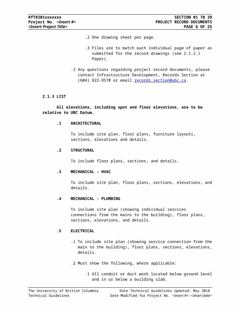
.2 One drawing sheet per page.
.3 Files are to match each individual page of paper as submitted for the record drawings (see 2.1.2.1 Paper).
The University of British Columbia Date Technical Guidelines Updated: May 2018 Technical Guidelines Date Modified for Project No. <Insert #>:<Insert date>
RfT#201xxxxxxx SECTION 01 78 39Project No. <Insert #> PROJECT RECORD DOCUMENTS<Insert Project Title> PAGE 5 OF 20
.3 Any questions regarding project record documents, please contact Infrastructure Development, Records Section at (604) 822-9570 or email [email protected].
2.1.3 LIST
All elevations, including spot and floor elevations, are to be relative to UBC Datum.
.1 ARCHITECTURAL
To include site plan, floor plans, furniture layouts, sections, elevations and details.
.2 STRUCTURAL
To include floor plans, sections, and details.
.3 MECHANICAL - HVAC
To include site plan, floor plans, sections, elevations, and details.
.4 MECHANICAL - PLUMBING
To include site plan (showing individual services connections from the mains to the building), floor plans, sections, elevations, and details.
.5 ELECTRICAL
.1 To include site plan (showing service connection from the main to the building), floor plans, sections, elevations, details.
.2 Must show the following, where applicable:
.1 All conduit or duct work located below ground level and in or below a building slab.
.2 All service, sub-service, and main riser conduits, all spare conduits stubbed in concealed spaces, and the location of all electrical equipment essential for safe system operation, such as end of line resistors, etc.
.3 All service ducts and cables for voltages above 705 volts, and for main communications cables.
.3 See also: Section 26 05 00 Electrical – General Requirements, 2.3 Project Record Drawing Requirements.
.6 CIVIL
To include site plan, elevations, and details.
.7 LANDSCAPE
To include site plan (showing lawn sprinkler services with connections), sections,
The University of British Columbia Date Technical Guidelines Updated: May 2018 Technical Guidelines Date Modified for Project No. <Insert #>:<Insert date>
RfT#201xxxxxxx SECTION 01 78 39Project No. <Insert #> PROJECT RECORD DOCUMENTS<Insert Project Title> PAGE 6 OF 20
elevations, and details.
.8 SURVEY
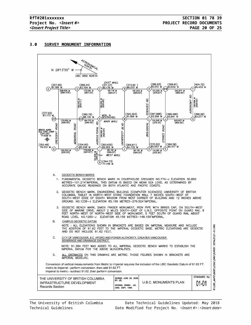
.1 Must show construction context in relation to the existing nearest official UBC monument, both in spatial locating (horizontal dimensions), as well as vertical reference – UBC Datum based elevations. (see Section 3.0 Survey Monument Information)
.2 To be created in UTM (Universal Transverse Mercator) and using NAD 83 Datum for compatibility with standard GIS functionality.
.9 DEMOLITION
.1 Drawings should clearly show the existing buildings, civil features and infrastructure in the vicinity of the project.
.2 The drawings should include clear definition of features and underground services to be demolished as well as the ones to be retained including horizontal and vertical survey dimensions relative to the nearest official UBC monument (see Section 3.0 Survey Monument Information).
2.1.4 CAD DRAWING PRODUCTION
.1 General Guidelines
.1 Drawing submissions should have all external reference drawings bound (BIND/INSERT) within the drawing. Bound layers must maintain layer names. Please check that the layer information is not lost.
.2 All drawings submitted must be purged of unused data such as blocks, layers, objects, and styles.
.3 Multiple drawing sheets must be broken down into separate drawings containing single sheets.
.4 AutoCAD ™ drawings shall not contain frozen layers. All unused entities on frozen layers should be erased and empty layers should be purged.
.5 All referenced image files (PNG, TIFF, JPG etc.) should be embedded as OLE objects in the drawings and should not be referenced outside the drawing.
.2 Scale and Units
.1 All drawings must be drafted in full scale metric units in model space such that one unit must equal to 1 millimeter.
.2 Site drawings drawn in 1:1 metre are acceptable.
The University of British Columbia Date Technical Guidelines Updated: May 2018 Technical Guidelines Date Modified for Project No. <Insert #>:<Insert date>

RfT#201xxxxxxx SECTION 01 78 39Project No. <Insert #> PROJECT RECORD DOCUMENTS<Insert Project Title> PAGE 7 OF 20
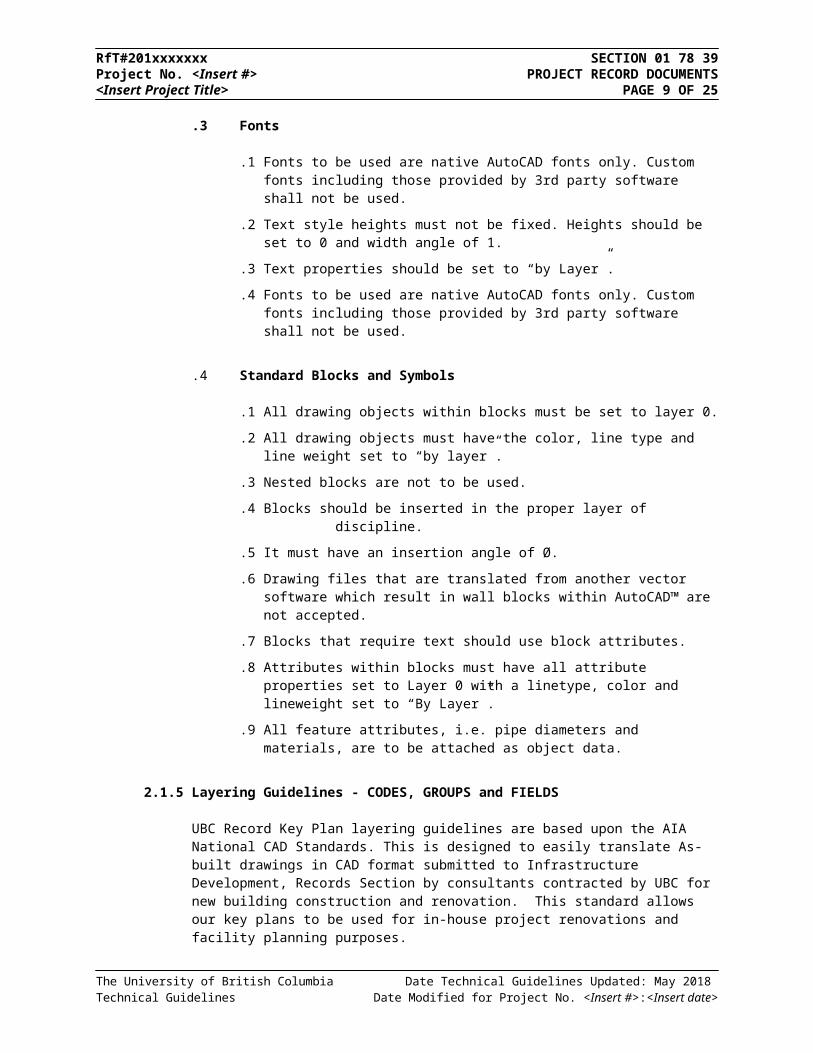
.3 Fonts
.1 Fonts to be used are native AutoCAD fonts only. Custom fonts including those provided by 3rd party software shall not be used.
.2 Text style heights must not be fixed. Heights should be set to 0 and width angle of 1.
.3 Text properties should be set to “by Layer”.
.4 Fonts to be used are native AutoCAD fonts only. Custom fonts including those provided by 3rd party software shall not be used.
.4 Standard Blocks and Symbols
.1 All drawing objects within blocks must be set to layer 0.
.2 All drawing objects must have the color, line type and line weight set to “by layer”.
.3 Nested blocks are not to be used.
.4 Blocks should be inserted in the proper layer of discipline.
.5 It must have an insertion angle of Ø.
.6 Drawing files that are translated from another vector software which result in wall blocks within AutoCAD™ are not accepted.
.7 Blocks that require text should use block attributes.
.8 Attributes within blocks must have all attribute properties set to Layer 0 with a linetype, color and lineweight set to “By Layer”.
.9 All feature attributes, i.e. pipe diameters and materials, are to be attached as object data.
2.1.5 Layering Guidelines - CODES, GROUPS and FIELDS
UBC Record Key Plan layering guidelines are based upon the AIA National CAD Standards. This is designed to easily translate As-built drawings in CAD format submitted to Infrastructure Development, Records Section by consultants contracted by UBC for new building construction and renovation. This standard allows our key plans to be used for in-house project renovations and facility planning purposes.
The CAD Layer Guidelines are organized as hierarchy. This arrangement accommodates expansion and addition of user-defined extensions to the layer list. Layer names are alphanumeric and use abbreviations that are easy to remember. This legibility is particularly important when CAD files are distributed among architects, consultants, and clients.
The University of British Columbia Date Technical Guidelines Updated: May 2018 Technical Guidelines Date Modified for Project No. <Insert #>:<Insert date>
DISCIPLINE MAJOR GOUP MINOR GROUP STATUS
Required Required Optional Optional

RfT#201xxxxxxx SECTION 01 78 39Project No. <Insert #> PROJECT RECORD DOCUMENTS<Insert Project Title> PAGE 8 OF 20
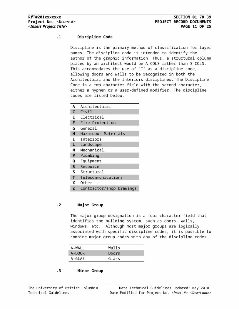
.1 Discipline Code
Discipline is the primary method of classification for layer names. The discipline code is intended to identify the author of the graphic information. Thus, a structural column placed by an architect would be A-COLS rather than S-COLS. This accommodates the use of "I" as a discipline code, allowing doors and walls to be recognized in both the Architectural and the Interiors disciplines. The Discipline Code is a two character field with the second character, either a hyphen or a user-defined modifier. The discipline codes are listed below.
A ArchitecturalC CivilE ElectricalF Fire ProtectionG GeneralH Hazardous MaterialsI InteriorsL LandscapeM MechanicalP PlumbingQ EquipmentR ResourceS StructuralT TelecommunicationsX OtherZ Contractor/shop Drawings
.2 Major Group
The major group designation is a four-character field that identifies the building system, such as doors, walls, windows, etc. Although most major groups are logically associated with specific discipline codes, it is possible to combine major group codes with any of the discipline codes.
A-WALL WallsA-DOOR DoorsA-GLAZ Glass
.3 Minor Group
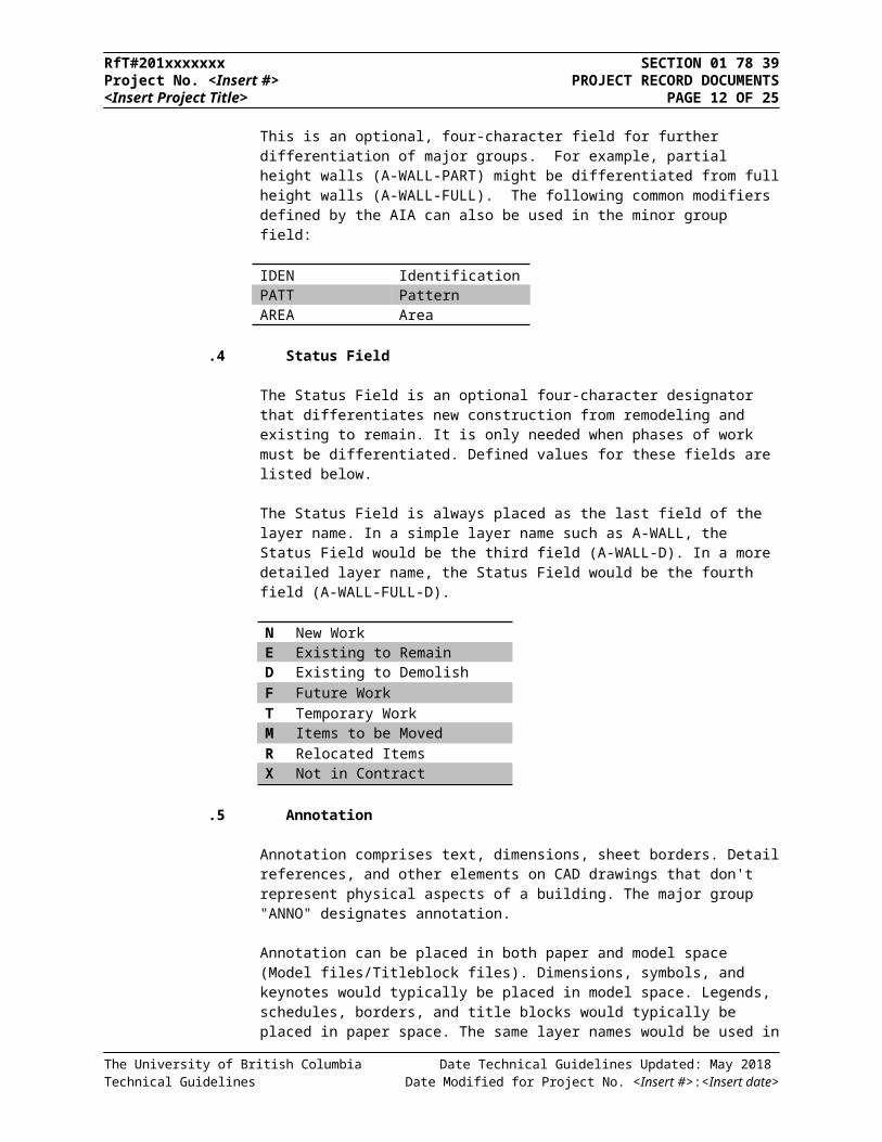
This is an optional, four-character field for further differentiation of major groups. For example, partial height walls (A-WALL-PART) might be differentiated from full height walls (A-WALL-FULL). The following common modifiers defined by the AIA can also be used in the minor group field:
IDEN IdentificationPATT PatternAREA Area
The University of British Columbia Date Technical Guidelines Updated: May 2018 Technical Guidelines Date Modified for Project No. <Insert #>:<Insert date>
RfT#201xxxxxxx SECTION 01 78 39Project No. <Insert #> PROJECT RECORD DOCUMENTS<Insert Project Title> PAGE 9 OF 20
.4 Status Field
The Status Field is an optional four-character designator that differentiates new construction from remodeling and existing to remain. It is only needed when phases of work must be differentiated. Defined values for these fields are listed below.
The Status Field is always placed as the last field of the layer name. In a simple layer name such as A-WALL, the Status Field would be the third field (A-WALL-D). In a more detailed layer name, the Status Field would be the fourth field (A-WALL-FULL-D).
N New WorkE Existing to RemainD Existing to DemolishF Future WorkT Temporary WorkM Items to be MovedR Relocated ItemsX Not in Contract
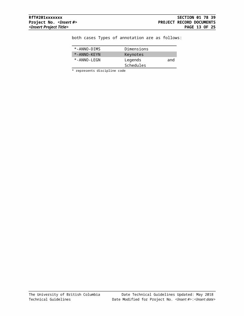
.5 Annotation
Annotation comprises text, dimensions, sheet borders. Detail references, and other elements on CAD drawings that don't represent physical aspects of a building. The major group "ANNO" designates annotation.
Annotation can be placed in both paper and model space (Model files/Titleblock files). Dimensions, symbols, and keynotes would typically be placed in model space. Legends, schedules, borders, and title blocks would typically be placed in paper space. The same layer names would be used in both cases Types of annotation are as follows:
*-ANNO-DIMS Dimensions*-ANNO-KEYN Keynotes*-ANNO-LEGN Legends and Schedules
* represents discipline code
The University of British Columbia Date Technical Guidelines Updated: May 2018 Technical Guidelines Date Modified for Project No. <Insert #>:<Insert date>

RfT#201xxxxxxx SECTION 01 78 39Project No. <Insert #> PROJECT RECORD DOCUMENTS<Insert Project Title> PAGE 10 OF 20
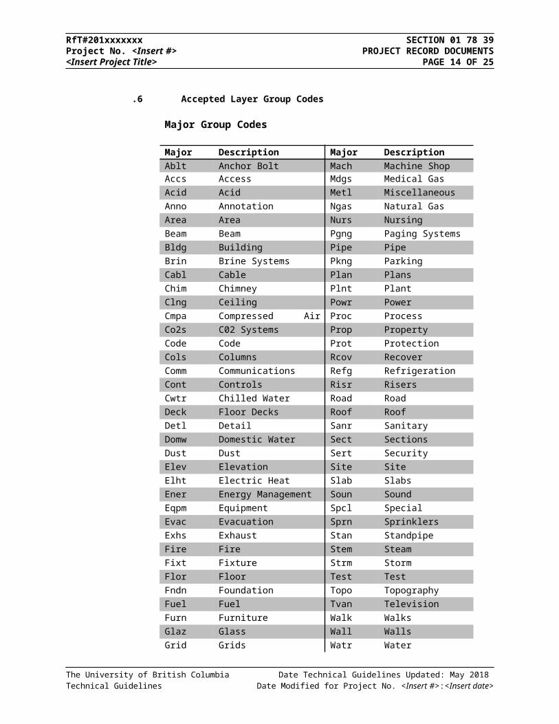
.6 Accepted Layer Group Codes
Major Group Codes
Major Code
Description Major Code
DescriptionAblt Anchor Bolt Mach Machine ShopAccs Access Mdgs Medical GasAcid Acid Metl Miscellaneous MetalAnno Annotation Ngas Natural GasArea Area Nurs NursingBeam Beam Pgng Paging SystemsBldg Building Pipe PipeBrin Brine Systems Pkng ParkingCabl Cable Plan PlansChim Chimney Plnt PlantClng Ceiling Powr PowerCmpa Compressed Air Systems Proc ProcessCo2s C02 Systems Prop PropertyCode Code Prot ProtectionCols Columns Rcov RecoverComm Communications Refg RefrigerationCont Controls Risr RisersCwtr Chilled Water Road RoadDeck Floor Decks Roof RoofDetl Detail Sanr SanitaryDomw Domestic Water Sect SectionsDust Dust Sert SecurityElev Elevation Site SiteElht Electric Heat Slab SlabsEner Energy Management Soun SoundEqpm Equipment Spcl SpecialEvac Evacuation Sprn SprinklersExhs Exhaust Stan Standpipe SystemsFire Fire Stem SteamFixt Fixture Strm StormFlor Floor Test TestFndn Foundation Topo TopographyFuel Fuel Tvan Television AntennaFurn Furniture Walk WalksGlaz Glass Wall WallsGrid Grids Watr WaterJois Joists Xref External References
The University of British Columbia Date Technical Guidelines Updated: May 2018 Technical Guidelines Date Modified for Project No. <Insert #>:<Insert date>
RfT#201xxxxxxx SECTION 01 78 39Project No. <Insert #> PROJECT RECORD DOCUMENTS<Insert Project Title> PAGE 11 OF 20
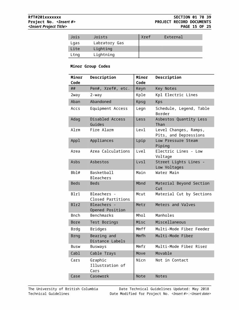
Lgas Labratory GasLite LightingLtng Lightning Protection
Minor Group Codes
Minor Code
Description Minor Code
Description
## Pen#, Xref#, etc. Keyn Key Notes
2way 2-way Kple Kpl Electric Lines
Aban Abandoned Kpsg Kps
Accs Equipment Access Legn Schedule, Legend, Table Border
Adag Disabled Access Guides Less Asbestos Quantity Less Than
Alrm Fire Alarm Levl Level Changes, Ramps, Pits, and Depressions
Appl Appliances Lpip Low Pressure Steam Piping
Area Area Calculations Lvel Electric Lines - Low Voltage
Asbs Asbestos Lvsl Street Lights Lines - Low Voltages
Bbl# Basketball Bleachers Main Water Main
Beds Beds Mbnd Material Beyond Section Cut
Blr1 Bleachers - Closed Partitions
Mcut Material Cut by Sections
Blr2 Bleachers - Opened Position
Metr Meters and Valves
Bnch Benchmarks Mhol Manholes
Bore Test Borings Misc Miscellaneous
Brdg Bridges Mmff Multi-Mode Fiber Feeder
Brng Bearing and Distance Labels
Mmfh Multi-Mode Fiber
Busw Busways Mmfr Multi-Mode Fiber Riser
Cabl Cable Trays Move Movable
Cars Graphic Illustration of Cars
Nicn Not in Contact
Case Casework Note Notes
Catv Cable TV Nplt Non-Plotting Information
Cdff Hvac Ceiling Diffusers Numb Power Circuit Numbers
Chil Chilled Water Occp Occupant or Employee Names
Circ Circutting Odff Other Diffusers
City City Ogep Fuel Oil General Piping
Clhd Sprinkler head (Ceiling) Open Ceiling and Roof
Cntr Center Lines Othd Sprinkler Head (Other)
The University of British Columbia Date Technical Guidelines Updated: May 2018 Technical Guidelines Date Modified for Project No. <Insert #>:<Insert date>
RfT#201xxxxxxx SECTION 01 78 39Project No. <Insert #> PROJECT RECORD DOCUMENTS<Insert Project Title> PAGE 12 OF 20
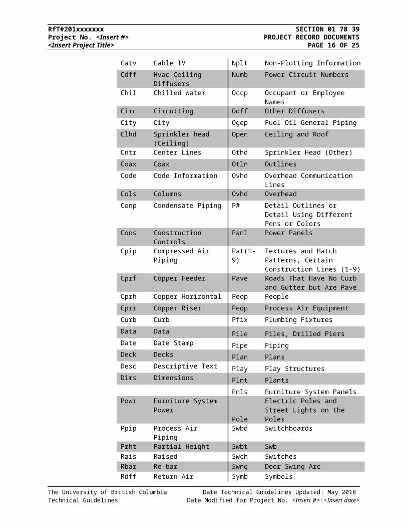
Coax Coax Otln Outlines
Code Code Information Ovhd Overhead Communication Lines
Cols Columns Ovhd Overhead
Conp Condensate Piping P# Detail Outlines or Detail Using Different Pens or Colors
Cons Construction Controls Panl Power Panels
Cpip Compressed Air Piping Pat(1-9) Textures and Hatch Patterns, Certain Construction Lines (1-9)
Cprf Copper Feeder Pave Roads That Have No Curb and Gutter but Are Pave
Cprh Copper Horizontal Peop People
Cprr Copper Riser Peqp Process Air Equipment
Curb Curb Pfix Plumbing Fixtures
Data Data Pile Piles, Drilled PiersDate Date Stamp Pipe PipingDeck Decks Plan PlansDesc Descriptive Text Play Play StructuresDims Dimensions Plnt Plants
Pnls Furniture System PanelsPowr Furniture System Power
PoleElectric Poles and Street Lights on the Poles
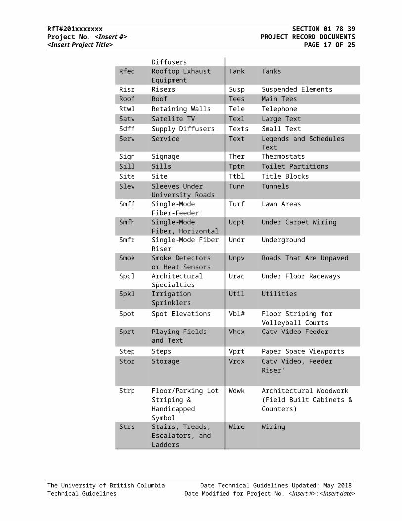
Ppip Process Air Piping Swbd SwitchboardsPrht Partial Height Swbt SwbRais Raised Swch SwitchesRbar Re-bar Swng Door Swing ArcRdff Return Air Diffusers Symb SymbolsRfeq Rooftop Exhaust
EquipmentTank Tanks
Risr Risers Susp Suspended ElementsRoof Roof Tees Main TeesRtwl Retaining Walls Tele TelephoneSatv Satelite TV Texl Large TextSdff Supply Diffusers Texts Small TextServ Service Text Legends and Schedules TextSign Signage Ther ThermostatsSill Sills Tptn Toilet PartitionsSite Site Ttbl Title BlocksSlev Sleeves Under University
RoadsTunn Tunnels
Smff Single-Mode Fiber-Feeder Turf Lawn AreasSmfh Single-Mode Fiber,
HorizontalUcpt Under Carpet Wiring
The University of British Columbia Date Technical Guidelines Updated: May 2018 Technical Guidelines Date Modified for Project No. <Insert #>:<Insert date>
RfT#201xxxxxxx SECTION 01 78 39Project No. <Insert #> PROJECT RECORD DOCUMENTS<Insert Project Title> PAGE 13 OF 20
Smfr Single-Mode Fiber Riser Undr UndergroundSmok Smoke Detectors or Heat
SensorsUnpv Roads That Are Unpaved
Spcl Architectural Specialties Urac Under Floor RacewaysSpkl Irrigation Sprinklers Util Utilities
Spot Spot Elevations Vbl# Floor Striping for Volleyball CourtsSprt Playing Fields and Text Vhcx Catv Video Feeder
Step Steps Vprt Paper Space ViewportsStor Storage Vrcx Catv Video, Feeder Riser'
Strp Floor/Parking Lot Striping & Handicapped Symbol
Wdwk Architectural Woodwork (Field Built Cabinets & Counters)
Strs Stairs, Treads, Escalators, and Ladders
Wire Wiring
The University of British Columbia Date Technical Guidelines Updated: May 2018 Technical Guidelines Date Modified for Project No. <Insert #>:<Insert date>
RfT#201xxxxxxx SECTION 01 78 39Project No. <Insert #> PROJECT RECORD DOCUMENTS<Insert Project Title> PAGE 14 OF 20
2.2 SPECIFICATIONS
2.2.1 FORMAT REQUIREMENTS
.1 PAPER
.1 Individual letter sized page (8.5” x 11”) compiled into a manual.
.2 DIGITAL
.1 Adobe Acrobat (PDF) which mirrors exactly the paper copy of each individual page for Project Specifications.
.2 Separate PDF files are required for each section of the specifications.
2.2.2 LIST
.1 ISSUED FOR CONSTRUCTION SPECIFICATIONS
.1 Describe in detail the materials, products and systems used for the project. They will be developed by the Architect, Specifier, and/or the Engineer.
.2 Specifications are to include each construction discipline, i.e. architectural, structural, plumbing, mechanical, and electrical.
.3 One (1) paper copy and one (1) PDF copy to be submitted to Infrastructure Development, Records Section within 60 days of Substantial Performance.
The University of British Columbia Date Technical Guidelines Updated: May 2018 Technical Guidelines Date Modified for Project No. <Insert #>:<Insert date>
RfT#201xxxxxxx SECTION 01 78 39Project No. <Insert #> PROJECT RECORD DOCUMENTS<Insert Project Title> PAGE 15 OF 20
3.0 SURVEY MONUMENT INFORMATION
The University of British Columbia Date Technical Guidelines Updated: May 2018 Technical Guidelines Date Modified for Project No. <Insert #>:<Insert date>
RfT#201xxxxxxx SECTION 01 78 39Project No. <Insert #> PROJECT RECORD DOCUMENTS<Insert Project Title> PAGE 16 OF 20
The University of British Columbia Date Technical Guidelines Updated: May 2018 Technical Guidelines Date Modified for Project No. <Insert #>:<Insert date>
RfT#201xxxxxxx SECTION 01 78 39Project No. <Insert #> PROJECT RECORD DOCUMENTS<Insert Project Title> PAGE 17 OF 20
4.0 UBC LAYERS IN USE
The following layer list is the current layers in use within UBC floor plans and campus maps. If additional layers are needed for drafting purposes, please refer to the AIA CAD Layer guidelines. New layer names may be added using the formatting rules listed in this section.
4.1 Building Floor Plans
The University of British Columbia Date Technical Guidelines Updated: May 2018 Technical Guidelines Date Modified for Project No. <Insert #>:<Insert date>
LAYER NAME DESCRIPTION COLOR LINETYPE
A-ANNO-DIMS DIMENSIONS WHITE CONTINUOUS
A-ANNO-NOTE CONSTRUCTION DATES/INFO GREEN CONTINUOUSA-ANNO-REDL BUILDING DELINEATOR LINES RED CENTERLINEA-ANNO-SYMB WASHROOM SYMBOLS BLUE CONTINUOUSA-ANNO-TEXT TITLE BLOCK TEXT / INFO./ UBC CREST / NORTH
ARROWSWHITE CONTINUOUS
A-ANNO-TTBL TITLE BLOCK BORDER/ LINES RED CONTINUOUSA-AREA-DESC ROOM USAGE DESCRIPTION YELLOW CONTINUOUSA-AREA-IDEN ROOM NUMBERS GREEN CONTINUOUS
A-AREA-PATT AREA HATCHES 253 CONTINUOUS
A-DOOR DOORS YELLOW CONTINUOUS
A-DOOR-IDEN EXTERIOR/INTERIOR DOOR LABELS GREEN CONTINUOUS
A-EQPM EQUIPMENT / ELEVATORS BLUE CONTINUOUSA-FLOR-PFIX PLUMBING FIXTURES BLUE CONTINUOUSA-FLOR-STRS STAIRS/ ESCALATORS/ TREADS/ LADDERS/ BALCONY
AND GUARD RAILS/ ARROWS AND TEXT/ RAMPS/ FLOOR LEVEL CHANGES
WHITE CONTINUOUS
A-FLOR-WDWK MILLWORK/ ARCH WOODWORK/ BUILT IN CABINETS & COUNTERS/ TOILET PARTITIONS
BLUE CONTINUOUS
A-FURN FURNITURE/ WORKSTATIONS/CHAIRS ETC… BLUE CONTINUOUS
A-GLAZ WINDOWS/GLAZED PARTITION/ SILLS YELLOW CONTINUOUS
A-PKNG PARKING LINES AND STALL NUMBERS WHITE CONTINUOUSA-ROOF ROOF OUTLINES WHITE CONTINUOUSA-WALL ARCHITECTURAL WALLS WHITE CONTINUOUSA-ROOF-PATT ROOF HATCHING / SURFACES WHITE CONTINUOUSL-SITE EXTERIOR WALKWAYS, STAIRS, PLANTERS ETC. BLUE CONTINUOUSS-GRID ARCHITECTURAL GRID / BUBBLE BLUE CENTERLINES-WALL STRUCTURAL WALLS/ COLUMNS CYAN CONTINUOUS
RfT#201xxxxxxx SECTION 01 78 39Project No. <Insert #> PROJECT RECORD DOCUMENTS<Insert Project Title> PAGE 18 OF 20
4.2 Site Base Map
LAYER NAME DESCRIPTION COLOUR LINETYPEC-BLDG BUILDING - FOOTPRINTS YELLOW CONTINUOUSC-BLDG FUTURE BUILDING - FUTURE MAGENTA CONTINUOUS
C-BLDG-DEMO BUILDING - DEMOLISHED 11 CONTINUOUS
C-BLDG-NUM BUILDING - NUMBER MAGENTA CONTINUOUS
C-BLDG-NUM-LARGE BUILDING - NUMBER LARGE RED CONTINUOUS
C-BLDG-TEXT BUILDING - TEXT MAGENTA CONTINUOUS
C-BLDG-TEXT-LARGE BUILDING - TEXT LARGE RED CONTINUOUS
C-BLDG-UC-LGTXT BUILDING - UNDER CONSTRUCTION TEXT
MAGENTA CONTINUOUS
C-BLDG-UNIT-NO BUILDING UNIT NUMBERS GREEN CONTINUOUS
C-PARK-TEXT-LARGE PARK TEXT YELLOW CONTINUOUS
C-PROP-LOT PROPERTY LOT LINES WHITE CONTINUOUS
C-PROP-LOT-EDITS 11 CONTINUOUS
C-PROP-LOT-SC PROPERTY LOTS LINES - SOUTH CAMPUS
WHITE CONTINUOUS
C-PROP-LOT-SC-TEXT PROPERTY LOT TEXT - SOUTH CAMPUS
WHITE CONTINUOUS
C-PROP-LOT-TEXT PROPERTY LOT TEXT WHITE CONTINUOUS
C-ROAD ROAD OUTLINES GREEN CONTINUOUS
C-ROAD-PKNG PARKING STALLS BLUE CONTINUOUS
C-ROAD-TEXT ROAD LABELS GREEN CONTINUOUS
C-ROAD-TEXT-LARGE ROAD LABELS - LARGE RED CONTINUOUS
C-SITE-MISC EXTRAS MAGENTA CONTINUOUS
C-SITE-TEXT SITE NAME MAGENTA CONTINUOUS
C-SITE-TEXT-LARGE SITE NAME - TEXT LARGE RED CONTINUOUS
C-SURV-MONU-LARGE MONUMENTS -LARGE RED CONTINUOUS
C-SURV-MONU-SMALL MONUMENTS WHITE CONTINUOUS
C-TOPO-HWATER HIGH WATER LINE GREEN CONTINUOUS
C-TOPO-LWATER LOW WATER LINE BLUE CONTINUOUS
C-TOPO-TEXT-LARGE CLIFF TOP -TEXT LARGE MAGENTA CONTINUOUS
C-TOPO-TOSL CLIFF TOP MAGENTA CONTINUOUS
The University of British Columbia Date Technical Guidelines Updated: May 2018 Technical Guidelines Date Modified for Project No. <Insert #>:<Insert date>
RfT#201xxxxxxx SECTION 01 78 39Project No. <Insert #> PROJECT RECORD DOCUMENTS<Insert Project Title> PAGE 19 OF 20
C-WALK WALKWAY OUTLINES / SLABS RED CONTINUOUS
DEDICATED PUBLIC ROADS DEDICATED PUBLIC ROADS 213 ACAD_ISO10W100
Defpoints Defpoints 53 CONTINUOUS
LEASEBORDER LEASBORDER BOUNDARIES 44 CONTINUOUS
L-GATE-TEXT-LARGE GATE LABELS - LARGE YELLOW CONTINUOUS
L-PLANT PLANTERS 94 CONTINUOUS
L-SITE-DEMO DEMOLISHED SITE FEATURES 11 HIDDEN
L-SITE-FENCWALL GATES/ FENCES MAGENTA FENCELINE1
L-SITE-POOL WATER FEATURES/ PONDS/ FOUNTAIN
BLUE CONTINUOUS
L-SITE-SPRT SPORTING AREAS AND FIELDS 9 CONTINUOUS
L-SITE-SPRT-DETAILS SPORT DETAILS 30 CONTINUOUS
L-SITE-WALL SITE WALLS BLUE CONTINUOUS
L-WALK-CRT WALKWAY - COURTYARDS BLUE CONTINUOUS
L-WALK-PLAZA WALKWAY - PLAZA BLUE CONTINUOUS
UEL BLDG UEL LAND BOUNDARIES YELLOW DASH
UNA LANDS UNA LAND BOUNDARIES 30 CONTINUOUS
VPORT VIEWPORT BLUE CONTINUOUS
4.3 Address Map
LAYER NAME DESCRIPTION COLOUR LINETYPEG-FUTURE-HATCH FUTURE DEVELOPMENT 200 Continuous
G-FUTURE-TEXT FUTURE DEVELOPMENT - TEXT 160 ContinuousG-POSTALAD POSTAL ADDRESS 10 Continuous
G-POSTALAD-ACADIA POSTAL ADDRESS - ACADIA 10 Continuous
G-POSTALAD-VST POSTAL ADDRESS - VST 10 Continuous
G-POSTALAD TEXT POSTAL ADDRESS - TEXT 10 Continuous
4.4 Legal Map
LAYER NAME DESCRIPTION COLOUR LINETYPEC-LGL-DL DISTRICT LOTS red CONTINUOUSC-LGL-DL-TEXT DISTRICT LOTS - TEXT yellow CONTINUOUS
C-LGL-EAS EASEMENT cyan CONTINUOUS
C-LGL-EAS-TEXT EASEMENT TEXT cyan CONTINUOUS
C-LGL-HOUS-AREA HOUSING AREA 10 CONTINUOUS
C-LGL-LEASE LEASED AREA yellow CONTINUOUS
C-LGL-LN LEGAL LINE white CONTINUOUS
C-LGL-LN-TEXT LEGAL LINE - TEXT magenta CONTINUOUS
C-LGL-LN-TEXT-L LEGAL LINE TEXT - LARGE magenta CONTINUOUS
C-LGL-ROAD-EASMNT ROAD EASEMENT 12 CONTINUOUS
C-LGL-TEMP TEMPORARY 10 NONUBC
C-PROP-LOT PROPERTY LOT white CONTINUOUS
The University of British Columbia Date Technical Guidelines Updated: May 2018 Technical Guidelines Date Modified for Project No. <Insert #>:<Insert date>
RfT#201xxxxxxx SECTION 01 78 39Project No. <Insert #> PROJECT RECORD DOCUMENTS<Insert Project Title> PAGE 20 OF 20
C-PROP-LOT-TEXT PROPERTY LOT TEXT white CONTINUOUS
C-SURV-IP SURVEY IRON PIN white CONTINUOUS
C-SURV-MISC SURVEY MISC white CONTINUOUS
C-SURV-MONU SURVEY MONUMENTS white CONTINUOUS
C-SURV-MONU-L SURVEY MONUMENT -LARGE red CONTINUOUS
C-SURV-PKNG-AREA SURVEY PARKING AREA 30 CONTINUOUS
C-SURV-PKNG1-AREA 31 CONTINUOUS
***END OF SECTION***
The University of British Columbia Date Technical Guidelines Updated: May 2018 Technical Guidelines Date Modified for Project No. <Insert #>:<Insert date>