ubi - unsorted block images - slava dubeyko - … ubi ubi block block block ubi ubi ubi ubi
TRANSCRIPT
UBI - Unsorted Block Images
Thomas Gleixner
Frank Haverkamp
Artem Bityutskiy

UBI - Unsorted Block Imagesby Thomas Gleixner, Frank Haverkamp, and Artem Bityutskiy
Copyright © 2006 International Business Machines Corp.
Revision History
Revision v1.0.0 2006-06-09 Revised by: haverRelease Version.

Table of Contents1. Document conventions...........................................................................................................................12. Introduction............................................................................................................................................2
UBI Volumes......................................................................................................................................2Static Volumes ..........................................................................................................................2Dynamic Volumes.....................................................................................................................3
3. MTD integration ....................................................................................................................................4Simple partitioning.............................................................................................................................4Complex partitioning .........................................................................................................................5
4. UBI design ..............................................................................................................................................6Eraseblock assignement .....................................................................................................................6
Enhancements...........................................................................................................................6Eraseblock headers.............................................................................................................................7
General Header format .............................................................................................................8Erase counter format.................................................................................................................8Volume identifier format...........................................................................................................9Erase counter update atomicity ..............................................................................................10
Volumes............................................................................................................................................10The layout volume..................................................................................................................11
Robustness ....................................................................................................................11FLASH space requirements .............................................................................................................12
Spare erase blocks ..................................................................................................................12Bad block parameter .....................................................................................................12Robustness ....................................................................................................................12
Space calculation ....................................................................................................................13Volume management........................................................................................................................13
Volume creation......................................................................................................................14Volume deletion......................................................................................................................14Volume resizing ......................................................................................................................14
Logical blocks ..................................................................................................................................14Block management...........................................................................................................................15
Block allocation......................................................................................................................15Block erasure ..........................................................................................................................15Block content movement ........................................................................................................15
Static volumes...............................................................................................................16Dynamic volumes .........................................................................................................16Scrubbing ......................................................................................................................17
UBI Initialization .............................................................................................................................18Future enhancements ..............................................................................................................18
Background operation ......................................................................................................................18Wear leveling....................................................................................................................................18
Enhancements.........................................................................................................................19Volume update..................................................................................................................................19Volume readout ................................................................................................................................20
iii
5. Programming Interfaces .....................................................................................................................21Kernel Space ....................................................................................................................................21
read .........................................................................................................................................21write ........................................................................................................................................22erase........................................................................................................................................22get_volume .............................................................................................................................23put_volume .............................................................................................................................23Enhanced: move_update.........................................................................................................23
Userspace Interface UBI ..................................................................................................................24sysfs interface .........................................................................................................................24
Deviceinfo (sysfs) .........................................................................................................24Volumeinfo (sysfs) ........................................................................................................25Examples.......................................................................................................................25
UBI device I/O functions........................................................................................................25create_volume ...............................................................................................................26delete_volume ...............................................................................................................26resize_volume ...............................................................................................................26
UBI volume I/O functions ......................................................................................................27start_update ioctl...........................................................................................................27open...............................................................................................................................28llseek .............................................................................................................................28read................................................................................................................................28write ..............................................................................................................................28
Volume update write mode..................................................................................28Enhancement: Dynamic volume write mode ......................................................29
6. MTD modifications ..............................................................................................................................30Maximum bad block parameter .......................................................................................................30
7. UBI kernel clients.................................................................................................................................31JFFS2 ...............................................................................................................................................31
Interface wrapping..................................................................................................................31Block erasure ..........................................................................................................................31Bad block handling.................................................................................................................31Write failure handling.............................................................................................................31Enhancements.........................................................................................................................32
Enhancement clients ........................................................................................................................32Block device emulation ..........................................................................................................32
Static read only block device ........................................................................................32Read/write block device................................................................................................32
8. Booting with UBI .................................................................................................................................33NOR FLASH system .......................................................................................................................33NAND FLASH system.....................................................................................................................33IPL and SPL .....................................................................................................................................34
Example volume layout ..........................................................................................................34IPL operations - Example: PPC44x using NAND..................................................................35
UBI support in boot-loader ..............................................................................................................37Device scan.............................................................................................................................37
iv

Scan result table ............................................................................................................37read volumes...........................................................................................................................38write volumes .........................................................................................................................38
v

List of Tables3-1. Simple partitioning scheme..................................................................................................................43-2. Complex partitioning scheme 1............................................................................................................53-3. Complex partitioning scheme 2............................................................................................................54-1. Scan time versus FLASH size ..............................................................................................................68-1. Partitioning for a NOR system ...........................................................................................................338-2. Partitioning for a NAND system ........................................................................................................34
vi
Chapter 1. Document conventionsAll sections marked as Enhancements are not part of the initial implementation. These sections areinformal and not part of the design review process. The sections are provided to point out futureextensions and answers to questions which came up during the design, i.e. scalability and speed. Theyhave to be considered in the base implementation in a way that the extensibility is not prohibited orunnecessarily complicated.
1

Chapter 2. IntroductionUBI is a general purpose flash management layer which has similar functionality as the Logical VolumeManager. The name was created with the picture of Unsorted Block Images in mind and accidentally isalso a Latin word, which means: where.
The basic idea is that the UBI layer provides the management for multiple logical volumes, which cancontain either static data or dynamic contents e.g file systems.
The management of multiple logical volumes on one or more flash devices of the same type requires thefollowing functionality:
• Bad block management
• Wear levelling across the device(s)
• Logical to physical block mapping
• Volume information storage
• Device information
UBI is not a traditional FLASH Translation Layer for block device emulation. UBI encapsulates theFLASH chip management from file systems and user space interfaces. A traditional FLASH TranslationLayer can easily be built on top of an UBI volume.
UBI addresses common FLASH handling mechanisms which have been redundantly implemented inFTLs and FLASH file systems. This allows FLASH file system developers to concentrate on the filesystem design while participating on the ongoing development and improvement of UBI.
The separation of the FLASH management and the file systems, FTLs and other possible users provides abetter layered concept than the intermingled solutions which are available today. Beside the replacementof redundant and single purpose implementations this provides a benefit in testability and error analysis.
UBI VolumesUBI volumes are container for different data contents. The UBI client can only access the data contents,not the UBI metadata.
UBI handles two volume types:
• static volumes
• dynamic volumes
2

Chapter 2. Introduction
Static VolumesStatic volumes contain only static data e.g. boot-code, operating-system images, initial-ramdisks, orread-only file-systems. Before writing blocks of a static volume, the data to be written into the blocks iscompletely known and treated read-only during later operation. Static volumes have:
• Linear usage of logical eraseblocks
• Known number of used eraseblocks
• CRC protection across all used eraseblocks
It is required that static volumes have a linear (consecutive) usage of logical erase blocks to simplifiyconsistency checks and allow fast access to the data contents. This applies especially for use cases, wherea boot loader has to load e.g. a kernel image from an UBI device. A static volume which does not haveall blocks in place is not usable.
Dynamic VolumesThe dynamic volumes contain data which can be changed during operation. Dynamic volumes are arequirement to provide support for writeable filesystems. Dynamic volumes have:
• Nonlinear usage of logical eraseblocks
• Unknown number of used eraseblocks
• CRC protection only for block moving
The users of dynamic volumes have to implement their own mechanisms for data integrity. UBI has noway to provide this because the content of a block is not known when the UBI header is written. Theusage pattern of the logical erase blocks is not limited and UBI handles holes in the allocated blocks bytreating them as empty, i.e. reading such a block returns an all 0xFF buffer of the requested size withoutaccessing the pyhsical FLASH chip, writing to an unallocated block results in allocation before the datacontents are written.
3
Chapter 3. MTD integration
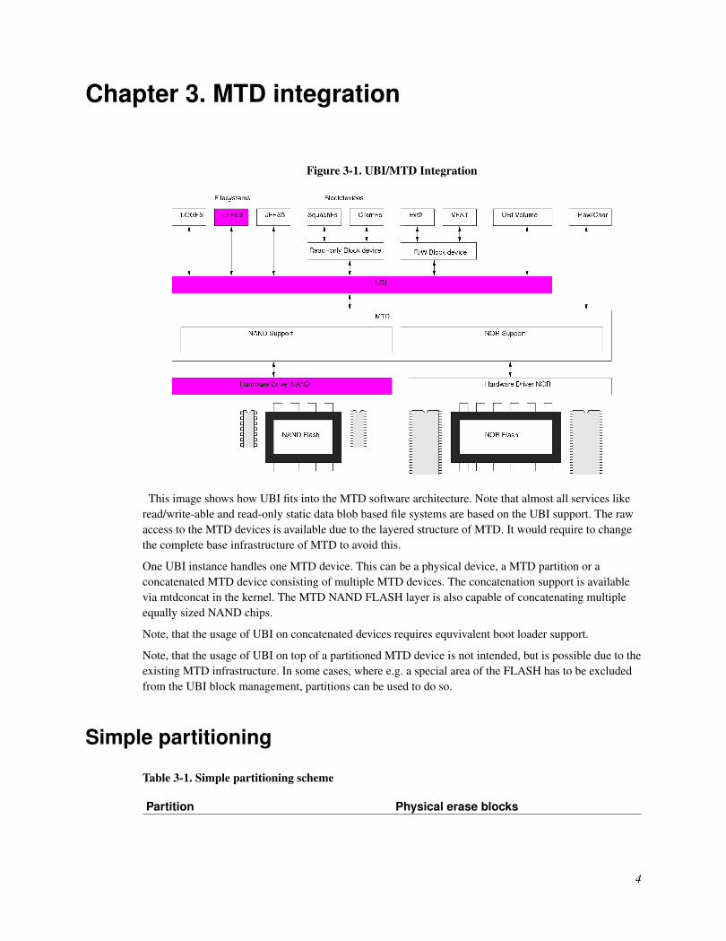
Figure 3-1. UBI/MTD Integration
This image shows how UBI fits into the MTD software architecture. Note that almost all services likeread/write-able and read-only static data blob based file systems are based on the UBI support. The rawaccess to the MTD devices is available due to the layered structure of MTD. It would require to changethe complete base infrastructure of MTD to avoid this.
One UBI instance handles one MTD device. This can be a physical device, a MTD partition or aconcatenated MTD device consisting of multiple MTD devices. The concatenation support is availablevia mtdconcat in the kernel. The MTD NAND FLASH layer is also capable of concatenating multipleequally sized NAND chips.
Note, that the usage of UBI on concatenated devices requires equvivalent boot loader support.
Note, that the usage of UBI on top of a partitioned MTD device is not intended, but is possible due to theexisting MTD infrastructure. In some cases, where e.g. a special area of the FLASH has to be excludedfrom the UBI block management, partitions can be used to do so.
Simple partitioning
Table 3-1. Simple partitioning scheme
Partition Physical erase blocks
4

Chapter 3. MTD integration
Partition Physical erase blocksBootloader 0 - 3
UBI 4 - max. blocks
This would allow to have wear levelling across the different volumes on the UBI partition and ensuresthat the bootloader area is not touched.
Another possibility is to mark the boot loader blocks with a "non movable" flag in the UBI header, soUBI does not include these blocks into the wear levelling. This requires an UBI aware boot loader designand might not be possible at all, when the boot code is required to start at offset 0 of a block.
Complex partitioning
Table 3-2. Complex partitioning scheme 1
Partition Physical erase blocksBootloader 0 0 - 3
UBI 4 - 63
Bootloader 1 64 - 67
UBI 68 - max. blocks
Table 3-3. Complex partitioning scheme 2
Partition Physical erase blocks ChipBootloader 0 - 3 0
UBI 4 - max. blocks 0
Bootloader 0 - 3 1
UBI 4 - max. blocks 1
For such complex paritioning schemes following usage variants are possible:
• Seperate UBI instances on the UBI partitons.
• Concatenation of the UBI partitions to a single MTD device and one UBI instance of top of theconcatenated device.
• No paritioning is necessary, when the boot loader or whatever non movable area of the FLASH can bemarked with UBI headers and excluded from wear levelling by marking the blocks as unmovable inthe header.
5

Chapter 4. UBI designThe design consists of two parts. The base design and the enhancements. The base design is simple andstraight forward, but has some limitations in terms of scalability. The enhancements are built on top ofthe base design and are marked accordingly. The enhancements do not change the interfaces and aredesigned with backward compability in mind.
Eraseblock assignementEach eraseblock of an UBI volume corresponds to one physical flash eraseblock. Although logicaleraseblocks appear contiguous to UBI users, the corresponding physical eraseblocks may be spread overthe underlying flash chip(s) in a non ordered way.
Basically UBI uses a table, referred to as the eraseblock assignement table (EAT), which maps logicaleraseblocks to physical eraseblocks. When a physical eraseblock is assigned to a volume, thecorresponding entry in EAT is changed. Also, if a logical eraseblock is used too actively and UBI decidesto assign it to another (less worn out) physical eraseblock, the corresponding entry in EAT is changed aswell.
In the basic UBI implementation the eraseblock assignement table is kept and maintained in RAM. TheEAT is built during the initial scan of the erase blocks. This does not scale very well, but it is simple toimplement and is acceptable for the FLASH sizes used in the first projects. Based on first tests 50us pererase block are required during the scan. The test machine was a 300MHz PPC board on a NANDFLASH device. The per block scan time consists of the FLASH read command time (~ 20us), the readout of the header and the analysis of the data. This sums up to following scan times:
Table 4-1. Scan time versus FLASH size
FLASH size Erase size Scan time64 MiB 16 KiB 200 ms
128 MiB 64 KiB 100 ms
256 MiB 64 KiB 200 ms
512 MiB 64 KiB 400 ms
1024 MiB 64 KiB 800 ms
512 MiB 128 KiB 200 ms
1024 MiB 128 KiB 400 ms
EnhancementsOf course it is possible to implement more comprehensive EAT management methods and to maintainEAT on Flash.
The scan based EAT build must be guaranteed as a fall back option, when a FLASH based EAT isinconsistent or unusable.
UBI manages an internal EAT Volume. The EAT volume is a dynamic UBI volume. For wear-leveling
6

Chapter 4. UBI design
reasons, the physical eraseblocks which are used for the EAT volume must be changed, but should bekept in an area near the beginning or the end of the FLASH device to limit the number of blocks to scanin order to find the EAT volume.
The challenge of FLASH based EAT management is the balance of consistency, access speed and lowFLASH update frequency. A possible solution was identified by the following algortihm. UBI writes anEAT table to flash, which consists of real block references and a number of erase block references whichhave to be scanned during the initialization of the UBI device. The content of these erase blocks areunknown before they have been scanned. The blocks are references to blocks in the free block pool ofUBI at the time the table was written to FLASH. These blocks are the ones which UBI gives out for newusage to UBI clients. During the scan UBI either adds or updates the block references in the FLASHtable. The table has to be updated on FLASH when:
• the blocks which are required to be scanned are used up and UBI has to add new blocks from the freeblock pool to this list.
• larger updates to the table happen, e.g by adding, removing, updating volumes.
• wear levelling requires large modifications of the erase block table.
Eraseblock headersThe basic flash management is based on erase blocks. UBI requires equally sized erase blocks. For blockmanagement UBI uses headers at the beginning of each erase block which reduces the usable size of theerase block slightly. The headers are used for two purposes:
• erase count tracking;
• volume identification.
Thus, there are two erase block header types in UBI:
• the erase counter;
• the volume identificator.
Note, the two eraseblock headers are written independently to flash, i.e., UBI requires to perform twowrite operations to the beginning of an eraseblock. For example, when a physical erase block is notassigned to any volume, it has only an erase count header, but as soon as it is assigned to a volume, thevolume identifier must be added.
The eraseblock headers have a fixed position, depending on FLASH type. On NOR the headers arewritten at the beginning of the erase block on consectutive adresses. On NAND flash devices the erasecount header is written to offset 0 of the block without ECC and later the volume header is written to thelast subscetion of the first page in the erase block. On small page devices (512 byte / page) this is at
7
Chapter 4. UBI design
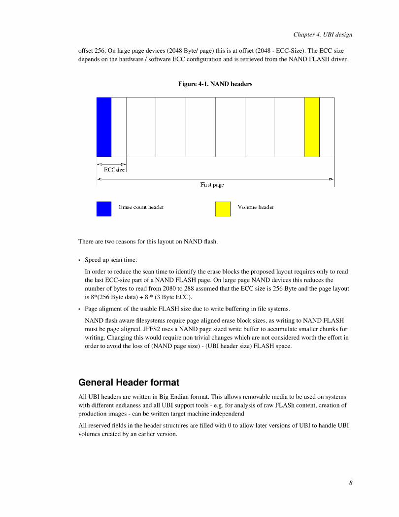
offset 256. On large page devices (2048 Byte/ page) this is at offset (2048 - ECC-Size). The ECC sizedepends on the hardware / software ECC configuration and is retrieved from the NAND FLASH driver.
Figure 4-1. NAND headers
There are two reasons for this layout on NAND flash.
• Speed up scan time.
In order to reduce the scan time to identify the erase blocks the proposed layout requires only to readthe last ECC-size part of a NAND FLASH page. On large page NAND devices this reduces thenumber of bytes to read from 2080 to 288 assumed that the ECC size is 256 Byte and the page layoutis 8*(256 Byte data) + 8 * (3 Byte ECC).
• Page aligment of the usable FLASH size due to write buffering in file systems.
NAND flash aware filesystems require page aligned erase block sizes, as writing to NAND FLASHmust be page aligned. JFFS2 uses a NAND page sized write buffer to accumulate smaller chunks forwriting. Changing this would require non trivial changes which are not considered worth the effort inorder to avoid the loss of (NAND page size) - (UBI header size) FLASH space.
General Header formatAll UBI headers are written in Big Endian format. This allows removable media to be used on systemswith different endianess and all UBI support tools - e.g. for analysis of raw FLASh content, creation ofproduction images - can be written target machine independend
All reserved fields in the header structures are filled with 0 to allow later versions of UBI to handle UBIvolumes created by an earlier version.
8

Chapter 4. UBI design
Erase counter format
struct ubi_ec_hdr {ubi32_t magic;uint8_t version;uint8_t padding1[3];ubi64_t ec;ubi32_t vid_hdr_offset;ubi32_t data_offset;uint8_t padding2[36];ubi32_t hdr_crc;
} __attribute__((packed));
magic The magic number to identify the erase count header. The value of this magicnumber is 0x55424923, which is ASCII: "UBI#".
version UBI version number to identify the UBI version which created this header.ec The number of erasures for this erase block.vid_hdr_offset The position of the volume header in the erase block. This is a constant value
depending on FLASH type but it allows to decode raw FLASH dumps withoutfurther information.
data_offset The position of the data in the erase block.hdr_crc CRC protection for the erase count header.
Volume identifier format
struct ubi_vid_hdr {ubi32_t magic;uint8_t version;uint8_t vol_type;uint8_t copy_flag;uint8_t compat;ubi32_t vol_id;ubi32_t lnum;ubi32_t leb_ver;ubi32_t data_size;ubi32_t used_ebs;ubi32_t data_pad;ubi32_t data_crc;uint8_t padding1[12];uint8_t ivol_data[UBI_VID_HDR_IVOL_DATA_SIZE];ubi32_t hdr_crc;
} __attribute__((packed));
9
Chapter 4. UBI design
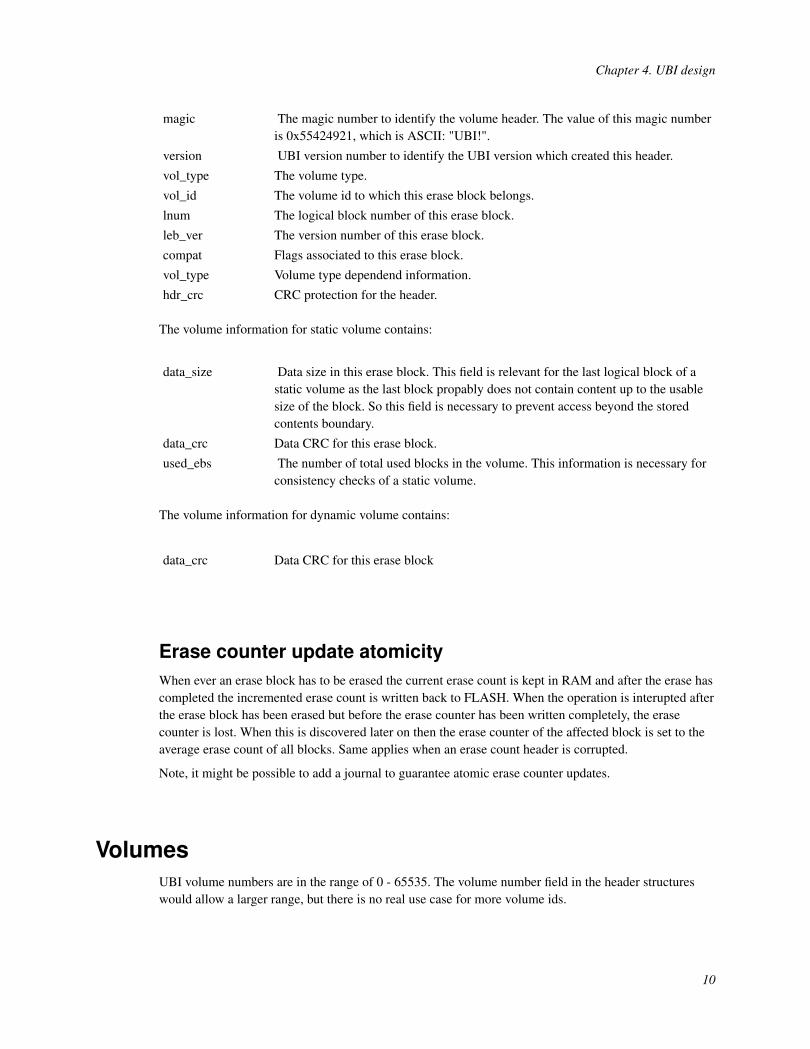
magic The magic number to identify the volume header. The value of this magic numberis 0x55424921, which is ASCII: "UBI!".
version UBI version number to identify the UBI version which created this header.vol_type The volume type.vol_id The volume id to which this erase block belongs.lnum The logical block number of this erase block.leb_ver The version number of this erase block.compat Flags associated to this erase block.vol_type Volume type dependend information.hdr_crc CRC protection for the header.
The volume information for static volume contains:
data_size Data size in this erase block. This field is relevant for the last logical block of astatic volume as the last block propably does not contain content up to the usablesize of the block. So this field is necessary to prevent access beyond the storedcontents boundary.
data_crc Data CRC for this erase block.used_ebs The number of total used blocks in the volume. This information is necessary for
consistency checks of a static volume.
The volume information for dynamic volume contains:
data_crc Data CRC for this erase block
Erase counter update atomicityWhen ever an erase block has to be erased the current erase count is kept in RAM and after the erase hascompleted the incremented erase count is written back to FLASH. When the operation is interupted afterthe erase block has been erased but before the erase counter has been written completely, the erasecounter is lost. When this is discovered later on then the erase counter of the affected block is set to theaverage erase count of all blocks. Same applies when an erase count header is corrupted.
Note, it might be possible to add a journal to guarantee atomic erase counter updates.
VolumesUBI volume numbers are in the range of 0 - 65535. The volume number field in the header structureswould allow a larger range, but there is no real use case for more volume ids.
10

Chapter 4. UBI design
Aside of user accesible volumes, UBI maintains internal volumes to store UBI related information e.g.volume information, flash based erase block assignment tables.
The volume numbers 0 - 65279 are available for user volumes. The volume number 65280 - 65535 arereserved for UBI internal volumes. The volume name strings for the internal volumes start with "ubi-".
There are no ordering restrictions for use volumes. The user can choose free volume numbers, e.g.0,7,8,300. This allows flexible association of volumes for user purposes.
Please note that the currently existing implementation does only support volumes numbers from 0 to 127for users.
The layout volumeVolume number 65280 (called layout volume) contains UBI layout information, i.e. number of volumes,their sizes and properties. The volume name string is "ubi-layout".
The layout volume requires two erase blocks. The data is stored redundantly. The volume information isstored as a consecutive list of volume information structures of all available user volumes.
The volume information ist stored in following structure.
struct ubi_vol_tbl_record {ubi32_t reserved_pebs;ubi32_t alignment;ubi32_t data_pad;uint8_t vol_type;uint8_t padding1;ubi16_t name_len;uint8_t name[UBI_VOL_NAME_MAX + 1];uint8_t padding2[24];ubi32_t crc;
} __attribute__ ((packed));
The layout volume is updated when a volume is created, deleted or resized. When one of theseoperations has been performed, a new layout volume is written to FLASH. The version number of thelogical erase block (always nr. 0) is increased and when the data has been written sucessfully the originallayout volume is erased. The robustness aspects of moving static content erase blocks which arediscussed further down apply to this mechanism.
The information about the volumes - reserved, used size - and the free space on the UBI device isaccessible via the sysfs interface of the UBI device and the UBI volumes.
Robustness
When the layout volume is defective, then UBI derives the volume sizes from the scan information.
The number of reserved blocks per volume is set to the largest logical erase block number found for eachvolume.
11
Chapter 4. UBI design
This allows the system to get into operational state. UBI emits appropriate warnings to the system logand provides status information via the sysfs interface.
FLASH space requirements
Spare erase blocksUBI needs to keep a number of spare erase blocks to ensure life time operation. These spare blocksreduce the total usable FLASH size.
The minimum requirement of UBI is one spare erase block for wear levelling and update mechanisms.
On some FLASH types e.g. NAND it is required to reserve a number of spare blocks for bad blockhandling. The minimum number is the number of initial bad blocks. The maximum number is thenumber of blocks which the system designer wants to reserve in order that UBI keeps fully operational.This is the total number of bad blocks per UBI device. There is no need to take bad blocks into accountwhen calculating the volume sizes. UBI guarantees full functionality up to the configured number of badblocks.
Bad block parameter
The maximum number of bad blocks is related to the FLASH type and FLASH size so it is a naturalchoice to extend the MTD info structure with a parameter which can hold the maximum number of badblocks which are acceptable on a particular device.
This requires also that the mtd concat layer sums up these parameters for concatenated devices.
A command line option to override the device driver value should be provided to make template driversusable and configurable for a specific hardware.
Robustness
When the number of bad blocks exceeds the specified maximum, then UBI denies write access to allvolumes. Manual interaction is necessary. The solution is to increase the maximum number of badblocks. This is only possible when there is free space on the UBI device. If the complete available spaceis used, then either volumes have to be deleted or size reduzed before increasing the number ofmaximum bad blocks.
The actual number of bad blocks is always available through the sysfs interface of the UBI device.
UBI also emits appropriate warning messages to the system log, when the delta of maximum and actualnumber of bad blocks is less than two.
It’s recommended to monitor the actual number of bad blocks via the sysfs interface of the UBI devicewith a surveillance application. This allows early information of service personal to ensure devicereplacement or change of parameters before the maximum number of bad blocks is reached and thedevice is switched to a restricted operational state.
12
Chapter 4. UBI design
Space calculationThe available space is calculated via:
nuser
= ntot
- nubi
wheren
user= number of erase blocks available to users
ntot
= number of physical erase blocksn
ubi= number of UBI reserved erase blocks
The number of UBI reserved blocks is calculated by:
nubi
= nmaxbad
+ nintvol
+ 1wheren
maxbad= number of maximum bad blocks
nintvol
= number of blocks used by internal volumes
The number of blocks used by UBI internal volumes is one - used for the layout volume - in the initialimplementation. Further enhancements like a flash based EAT will require more reserved blocks forinternal purposes. The total number of bytes available for content storage is:
bytestot
= nuser
* bytesblock
wherebytes
tot= number of bytes available for storage
bytesblock
= number of bytes available for storage per erase block
The number of bytes available for storage per eraseblock is:
bytesblock
= bytesphys
- bytesubi
wherebytes
phys= number of bytes per erase block
bytesubi
= number of bytes reserved by UBI
The number of bytes reserved by UBI is:
For NOR:bytes
ubi= 2 * sizeof(eraseblock header)
For NAND:bytes
ubi= NAND page size
The size of an UBI volume is always a multiple of the number of bytes which are available for contentstore per erase block.
13
Chapter 4. UBI design
Volume managementUBIs volume management is based on space accounting. The total number of erase blocks available foruser volumes can not be exceeded by the sum of erase blocks which are reserved for the volumes. Evenwhen volumes do not use up the reserved space, UBI does not implement overcommitment mechanisms.
UBI implements three functions related to volume management:
• Volume creation
• Volume deletion
• Volume resizing
Volume creationA new volume can be created as long as there is enough free space available. The creator requests thesize of the new volume and UBI aligns it to a multiple of bytes per erabe block which are available forcontent storage.
In order to support a block device layer on top of UBI it is necessary to provide an optional parameterwhich can adjust the minimum unusable space - which is 2 * sizeof (ubi header) to a greater size whichensures that the usable space of an erase block is a multiple of the block device sub block size.
Volume deletionAn existing volume can be deleted, when it is not in use. The erase blocks which were allocated for thevolume are erased and put back into the free block pool. The erase operation must be completed beforethe volume resize can be propagated into the layout volume.
Volume resizingAn existing volume can be resized, when it is not in use.
In case the volume is expanded the required space must be free in the ubi device.
When the volume size is reduced, then the number of used blocks in the volume must be less or equalthan the new size. Note, that by default UBI will not reduce the size of dynamic volumes unless thenumber range of logical erase blocks which will be removed from the volume contains only unusedblocks. A specical parameter allows to override this default. UBI then moves the contents of logicalblocks from the number range which will be removed from the volume to unused logical erase blockswith lower numbers before resizing the volume. The move operation must be completed before thevolume resize can be propagated into the layout volume.
14

Chapter 4. UBI design
Logical blocksAn UBI volume consists of logical blocks. The maximum number of logical blocks for a volume isspecified by the size requirements given at volume creation or resizing.
The logical blocks associated to a volume can hold the logical block numbers 0 to maxblocks-1. Thelogical block numbers of a volume are unique.
For short periods of time block moving, scrubbing and wear levelling functions can create a secondinstance of a logical block number. UBI ensures that write access to such blocks is not possible.
Block management
Block allocationUBI uses late block allocation to ensure optimized wear levelling. A block is allocated and the volumeheader is written to it when a write access happens to an logical block number which has not beenallocated yet. All erase blocks which are not allocated for any volume are kept in a free block pool.
Block erasureBlock erasure is triggered by:
• erase request from an UBI client
• volume deletion
• volume content update
• internal block move operations due to wear levelling
• internal block move operations due to scrubbing
In most cases the block erasure is an asynchronous operation and is deferred to a background operation.Synchronous block erasure requirements are marked in the sections of the functionality which requiresthem.
Block content movementBlock content movement can be triggered by:
• wear levelling
• bit flip correction (scrubbing)
• volume resizing
15

Chapter 4. UBI design
In most cases the movement of block contents is an asynchronous operation and is deferred to abackground operation. Synchronous requirements are marked in the sections of the functionality whichrequires them.
When UBI decides to move a logical eraseblock to another physical eraseblock due to wear-leveling orscrubbing considerations, it needs to:
• move the contents of the previous physical eraseblock to the new physical eraseblock;
• update the corresponding entry in the EAT table.
• erase the old erase block
Static volumes
The update mechanism for blocks of a static volume is simple. The volume header of the erase block iscopied and the version number of the erase block is incremented. The header CRC is updated, but thedata CRC is unchanged. Then the block content is copied to the new block. When the contents have beencopied completely, the original erase block is erased.
In case the copying of block contents is interrupted before all data has been transferred, then UBI detectstwo versions of the same logical block in a volume. UBI tries to use the one with the higher versionnumber first. Due to the interruption of the copying the data CRC is invalid and UBI falls back to theblock with the lower version number. The incomplete block is erased and a new move operation can bestarted.
In case the moving operation is interrupted before the original erase block has been erased, then UBIdetects two versions of the same logical block in a volume. UBI tries to use the one with the higherversion number first. In this case the data CRC of this block is valid and the block with the lower versionnumber can be erased.
The moving operation is not blocking the read access to the data contents. Until the contents arecompletely copied the data can be read from the original erase block.
Dynamic volumes
For dynamic volumes a slightly different mechanism is necessary. UBI blocks write access to the logicalerase block for the move process. A CRC checksum is generated over the complete data area of theblock. This checksum is written to the volume header of the new erase block along with an incrementedversion number of the logical block and an updated header CRC. Then the block content is copied. Note,that empty content (containing all 0xff) is not copied, but accounted in the data CRC. When the blockcontent has been copied completely then the original erase block is erased and the write access to thelogical block is enabled again.
In case the copying of block contents is interrupted before all data has been transferred, then UBI detectstwo versions of the same logical block in a volume. UBI tries to use the one with the higher versionnumber first. Due to the interruption of the copying the data CRC is invalid and UBI falls back to theblock with the lower version number. The incomplete block is erased and a new move operation can bestarted.
16

Chapter 4. UBI design
In case the moving operation is interrupted before the original erase block has been erased, then UBIdetects two versions of the same logical block in a volume. UBI tries to use the one with the higherversion number first. The data CRC is valid, so the block with the lower version number can be erased.Until the original block has been erased write access to the logical block has to be disabled.
The moving operation is not blocking the read access to the data contents. Until the contents arecompletely copied the data can be read from the original erase block. Write access to an logical blockwhich contents are moved is not allowed until the moving operation has been finished completely, i.e. theoriginal erase block must have been erased before write access can be granted again. Write access toother erase blocks of the volume is allowed during a moving operation.
Scrubbing
Scrubbing is a safety mechanism to handle bit flips. When a bit flip occures and the ECC algorithm canrecover the original data contents, then the contents of the affected block are moved to a free blockaccording to the algorithms described above. The scrubbing operation is scheduled in the background,when a in kernel or user space initiated read operation detects a bit flip.
The following figure shows how an UBI block of a file-system volume is treated, when a bit-error hasoccurred. UBI block A) needs to be copied into a free block to eliminate the bit-error. The versionnumber is increased and the CRC is calculated and added to the new UBI header. Because the data of thisparticular kind of UBI block is controlled by the file-system using it, the CRC is usually unused (likeA)). But when the block is scrubbed the data CRC is calculated to be able to identify the latest validversion of the block when the copy/erase process should have been interrupted.
Figure 4-2. Scrubbing of an UBI block in a filesystem volume
• Imagine block A) and B) exist at the same time. Here the block with the highest version numbershould be kept if and only if the data CRC is valid. The existence of both blocks can happen due to aninterruption before or while A) is deleted. In the latter case block A) has undefined data but B) is stillvalid.
17

Chapter 4. UBI design
• The transformation from block B) into block C) happens when the file-system needs to add more datato the non-empty block. In this case the data CRC becomes invalid. When two blocks exist only thenewer blocks data CRC is to be checked. This can be seen in the next step.
• Over the time a bit-error occurred in block C) which needs now to be copied to a new block D). Thiscase is the same like the first one. The data CRC is now calculated, the version number is increased byone and the new block D) is written. If interrupted C) and D) exist at the same time and the CRC of thenewer block D) is used to determine its validity. If D)’s CRC is invalid C) is used.
The displayed algorithm ensures that in any cases where the scrubbing process can be interrupted a validcopy of the UBI block exists can be identified by the block’s version number and/or the associated dataCRC.
UBI InitializationThe first simple UBI implementation performs full flash scan in order to find out positions of layoutvolume eraseblocks, to build the EAT table. When UBI scans flash media, it reads eraseblock headersand builds all the necessary data structures in main memory.
The scan based mechanism requires seperate scans in the boot loader and the kernel. It would betechnically possible to hand the boot loader scan table to the kernel, but this would require a more unifiedboot loader kernel interface across the different architectures and boards. Such an interface is notavailable and therefor such an attempt would be a single purpose hack rather than a useful genericsolution.
Future enhancementsIn order to avoid scanning of the complete FLASH it is necessary to implement a flash based EATmechanism.
Background operationUBI uses a background thread or utilizes the available background Linux worker threads for followingoperations:
• Wear levelling
• Block moving
• Block scrubbing
• Block erasure
18

Chapter 4. UBI design
Wear levelingWear levelling is done across the complete flash device with help of the erase counters.
The default selection criteria is to use the blocks with the lowest erase count.
UBI keeps track of the maximum and minimum erase counts over all erase blocks. To avoid permanentwear levelling activities a treshold of 5000 erase cycles is introduced. Wear levelling is checked whenever a block has been erased. When the newly erased block is the block with the highest erase count andthe delta of erase cycles versus the block with the lowest erase count has reached the treshold then UBIselects a long term storage block with a low erase count and copies the block contents to the block withthe high erase count using the block moving function. When copying is done the block with the lowerase count is erased and enqueued into the free block pool. In case of a very low number of free blocksthis may slow down the allocation of erase blocks for UBI clients.
The free - unallocated - erase blocks are kept in a sorted list in erase count order to ensure O(1) selectionof a block when allocation is requested.
EnhancementsAn UBI client might provide a callback function, which is called by UBI before trying to move blockcontent. The rationale of the function is, that the client might veto the movage of the block contents. Onereason for this might be that the client has this block in use for writing or has the block scheduled forgarbage collection. In such a case the moving of the block content makes no sense and can be deferred toa later time or the block is made available by garbage collection in the near future.
A function to signal the intended use of a logical erase block can be implemented. An UBI client couldsignal whether the block is used for long term or short term storage. This would allow to implementmore efficient wear levelling algorithms.
Volume updateUpdate of UBI volumes happen from userspace. The update mechanisms writes raw data contentswithout meta information. The meta information - i.e. Volume headers - are created by UBI on the fly.
The update tool opens the ubi volume and issues a start_update ioctl command. The argument ofstart_update is the total number of bytes, which will be written to the volume. This is necessary toprovide robustness versus interruption of the update and to calculate the number of total used blocks forstatic volumes. UBI checks whether the requested data length fits into the volume.
In case of updating a dynamic UBI volume, first a block is written with a volume update headercontaining the reserved VOLUME_UPDATE volume id and the logical block number 0. The number ofthe volume which is updated is stored in the data payload of this block. The existence of this blocksignals the update in progress. UBI erases the eventually existing blocks which are assigned to thevolume. The erase of the existing blocks has to be completed before new content can be written.
When a static volume is updated, writing a volume update marker is not necessary. The completenessand correctness of the data is ensured if all used erase blocks are found and their header and data CRC iscorrect.
19

Chapter 4. UBI design
Now the data content is written and UBI creates the volume headers for the logical erase blocks andcalculates the data CRC in case of a static volume.
When all data of the dynamic volume has been written successfully, then the update volume block iserased.
Note, that a size of 0 bytes given to the start_update command is valid. This creates the update inprogress block and erases the existing logical erase block. The update in progress marker is removedafter all existing blocks have been erased. This is useful to empty a volume.
When a volume update is interrupted then the block with the reserved update volume id is on the FLASHand invalidates all other eventually existing logical erase blocks for the volume which is protected. Anew update has to be started. A possible UBI client which tries to access such a volume is informed byan appropriate error code and the access is denied. See also "Programming Interfaces". In the volumelayout the volume still exists, but the number of used blocks is zero. UBI does automatically erase theeventually existing blocks of such an volume, but the block indicating volume update in progress is noterased. User interaction is necessary to resolve this. The update in progress block can be removed by anew update command or by deleting the volume.
The usage of an extra erase block to indicate an update in progress looks like a waste, but for dynamiccontent volumes there is no other way to ensure the completeness of an update operation before allowingthe usage of such a volume. This might change once the enhancements of a journal / super block havebeen implemented. On the other hand the update in progress marker is perfectly reasonable because suchupdates happen rather seldom during the lifetime of a device and it allows a simple scan basedidentification of volume completeness e.g. in a boot loader.
Note, that the extra block is an per UBI device overhead which is reserved anyway for wear levelling andblock move purposes. This limits the number of concurrent volume updates to one. Thats not a bigproblem as volume updates are usually done in a code update situation where time is not the criticalfactor. Also the limiting factor of an update is the FLASH device itself which allows no erase / programoperations in parallel.
Partial updates of volumes are not possible.
Volume readoutThe data contents of an UBI volume can be read out from user space. A read out can only be performedon unused volumes or on volumes with read only client.
20
Chapter 5. Programming Interfaces
Kernel Space
• read
• write
• erase
• get_volume
• put_volume
• Enhanced: move_modify
The kernel space interfaces access the volumes by logical block number and offset inside of the logicalblock rather than providing a full offset which would have be converted into logical block number andoffset inside of the block for following reasons.
A FLASH aware file system has to be aware of erase block boundaries anyway and usually operates onblocks. The currently used MTD interface which requires full offsets is called by adding the in blockoffset to the block base offset. So the seperate information is available anyway. Of course could UBI dealwith the full offset, but due to the fact that UBI reduces the net data size of an erase block this wouldrequire a (64bit offset) / (usable block size) division. 64 / 32 bit divisions are perfomance critical on 32bit CPUs. Otherwise there would be an limitation of 32 bit offsets, which would limit UBI to 4GiBmaximum device size.
The implementation of a block device on top of UBI will divide the UBI erase block into smaller sizedblocks which are exposed to the block device interface. There is an explicit requirement that the size ofthe usable UBI block size must be a multiple of the size of these sub blocks. The size of the sub blocks isalso influenced by the NAND page size, when the block device is writeable. The minimum sensible subblock size will be 512 byte, which allows the usage of pure 32 bit operations to calculate the logicalblock number. This increases the device limit to 2 Terrabyte which seems to be a reasonable limitation.
readThe read function takes following arguments:
• volume descriptor
• block number
• offset
• length
• buffer pointer
21

Chapter 5. Programming Interfaces
The return value is the number of bytes read or an error code.
When an UBI client of a dynamic volume wants to read an unallocated logical erase block, then UBI fillsthe requested number of bytes in the data buffer with 0xFF without accessing the FLASH chip.
The following error codes can be returned:
-EIO A fatal I/O error occured, e.g. device removal, timeouts.-EINVAL An invalid block number, offset or length was requested.
UBI does not provide a read_ecc version because this is not relevant for the UBI client and the eccrelated problems are handled inside UBI itself.
writeThe write function takes following arguments:
• volume descriptor
• block number
• offset
• length
• buffer pointer
The return value is the number of bytes written or an error code. When the offset is 0 and no physicalerase block has been assigned to the logical erase block then UBI assignes automatically a physical eraseblock and writes the volume header. This function is only available for dynamic content volumes.
The following error codes can be returned:
-EIO A fatal I/O error occured, e.g. device removal, timeouts.-EROFS Attempt to write to a read only volume.-EINVAL An invalid block number, offset or length was requested.
The write operation is synchronous. UBI guarantees that data has been written to FLASH when thefuntion returns without an error.
Write errors which are detected by the hardware level driver - e.g. write-verify of the NAND driver - arehandled by UBI before returning from the write function. In such a case UBI moves the existing blockcontents to a free erase block according to the block movement mechanisms and writes the data in thedata buffer to this new block when the block content move operation has been completed.
UBI does not provide a write_ecc version because this is not relevant for the UBI client and the eccrelated problems are handled inside UBI itself.
22

Chapter 5. Programming Interfaces
eraseThe erase function takes following arguments:
• volume descriptor
• block number
The erase function schedules the logical erase block for erasure. UBI ensures that the physical eraseblock has been erased before the next write access to the same logical block number, which allocates anew physical erase block. This function is only available for dynamic content volumes.
The following error codes can be returned:
-EIO A fatal I/O error occured, e.g. device removal, timeouts.-EROFS Attempt to erase a block on a read only volume.-EINVAL An invalid block number was requested.
get_volumeThe get_volume function takes following arguments:
• ubi device id
• volume id
• mode read/write - readonly
The function must be called before any of the other functions can be used. The function marks thevolume as used. Only one user per volume is allowed.
On success the function returns a pointer to the UBI volume description structure. Otherwise an errorcode is returned.
The following error codes can be returned:
-ENODEV The requested volume does not exists.-EROFS Attempt to get R/W access on a read only volume.-EBUSY The volume is already in use.-EUCLEAN The volume is corrupted.
put_volumeThe put_volume function takes following arguments:
• volume descriptor
The function is called to finish the usage of a volume. The function marks the volume as unused.
23

Chapter 5. Programming Interfaces
Enhanced: move_updateThe move_update function takes following arguments:
• volume descriptor
• block number
• offset
• length
• buffer pointer
The function moves the contents of a logical erase block to a free block using the basic block movingalgorithm of UBI. The block moving algorithm has to be extended to allow the update of the blockcontent on the fly.
This function allows to implement robust update of block contents, which is a preliminary for r/w blockdevice emulation.
Userspace Interface UBIThe user space interface is implemented in sysfs. Device nodes for I/O operations have to be created bythe udev mechanism in userspace.
The sysfs interface provides mostly read only information about the UBI device and the UBI volumes.The operational functions are accessible via character devices, which have to be created by the udevmechanism.
The sysfs interface exposes all status information about the UBI device and the volumes in a humanreadable way. This has several advantages over ioctl based binary information exchange. The sysfsinterface allows simple script based analysis and monitoring and there is no need to keep changes of datastructures between kernel and userspace synchronized.
The enumeration of available volume ids is a simple
‘ls /sys/devices/ubi/0/volumes‘
command.
sysfs interface
Deviceinfo (sysfs)
• nr. volumes
• nr. bad blocks
24

Chapter 5. Programming Interfaces
• nr. used blocks
• nr. free blocks
• blockbitmap
• stats - erase count statistics, bitflips
• debug switch
Volumeinfo (sysfs)
• name
• size
• type/flags
• used blocks
• blockbitmap
• status
Examples
/sysfs/devices/ubi/0/device_info/nr_volumesnr_usednr_freebitmaperase_statsdevice - mtdnamevolumes/0/used_size
bitmap...
UBI device I/O functionsThe UBI device provides following ioctl functions:
• create_volume
• delete_volume
• resize_volume
25

Chapter 5. Programming Interfaces
create_volume
The create_volume ioctl takes following arguments:
• volume id
• volume type
• volume size
• volume name
• minimum subblock size
The volume type is either dynamic or static. The minimum subblock size is either 0 to select the systemdefault or a value to adjust the subblock size for UBI clients e.g. a block device layer. See also section"Volume creation" in the chapter "UBI design".
The create_volume ioctl is a synchronous operation.
The volume must not exist and the size of the volume must fit into the free size of the ubi device.
The following error codes can be returned:
-EEXIST The volume exists already-EINVAL An invalid parameter was given.-ENOSPACE The requested size is not available on the device.
delete_volume
The delete_volume ioctl takes following arguments:
• volume id
The volume must exist and not be in use.
The delete_volume ioctl is a synchronous operation. After returning without an error the volume and allits data is deleted in flash.
The following error codes can be returned:
-EBUSY The volume is in use and can not be deleted.-EINVAL An invalid parameter was given.
resize_volume
The resize_volume ioctl takes following arguments:
• volume id
26

Chapter 5. Programming Interfaces
• volume size
The volume must exist and not be in use. In case the volume is expanded the required space must be freein the ubi device. When the volume size is reduced, then the number of used blocks in the volume mustbe less or equal than the new size.
The following error codes can be returned:
-EBUSY The volume is in use and can not be resized.-EINVAL An invalid parameter was given.-ENOSPACE The requested size is not available on the device.
UBI volume I/O functionsThe UBI volume provides following ioctl functions:
• start_update
The UBI device provides following file I/O functions:
• open
• llseek
• read
• write
• close
start_update ioctl
The start_update ioctl takes following arguments:
• data size
The data size must be less or equal to the reserved size of the volume. When the size is valid then theexisting erase blocks of the volume are erased. This is a synchronous operation to ensure that no remainsof the previous volume are on FLASH before writing the new image data. This call is necessary to enablewrite access to the volume through the write file I/O function.
The following error codes can be returned:
-EBUSY Another operation is active so the volume can not be updated.-EINVAL An invalid parameter was given.
27

Chapter 5. Programming Interfaces
-ENOSPACE The requested size is not available on the device.
open
The open interface is the standard open system call. A file descriptor is returned on success.
The following error codes can be returned:
-EBUSY The volume is in use and can not be opened.-ENODEV The volume is not available.
llseek
The llseek interface is the standard lseek system call.
The following error codes can be returned:
-EINVAL An invalid parameter was given.-EUCLEAN The volume is corrupted.
read
The read interface is the standard read system call. The volume data content is read in the order of logicalerase blocks. The start offset can be set by the llseek function.
The following error codes can be returned:
-EINVAL An invalid parameter was given.-EUCLEAN The volume is corrupted.
write
The write interface is the standard write system call. The volume data content is written in a consecutivebinary stream. The write call which contains the last byte of the stream is a synchronous operation toensure that the complete data is written to FLASH.
There are two write modes possible
• Volume update write mode
• Dynamic volume write mode
Dynamic volume write mode is an enhancement. Volume update write mode is a basic requirement.
Volume update write mode
Volume update is available for static and dynamic volumes.
28
Chapter 5. Programming Interfaces
The start_update ioctl is called immidiately before the write. The complete volume data has to be writtenin consecutive order. The write is terminated when the size of data which was announced via thestart_update ioctl has been written.
The following error codes can be returned:
-EINVAL An invalid parameter was given.
Enhancement: Dynamic volume write mode
This write mode is only available for dynamic volumes.
The application has to llseek to the offset which should be written to. The application has to be aware ofbasic FLASH handling restrictions. Writes to non empty locations are not allowed. Writes accrosslogical erase block boundaries are not allowed.
The following error codes can be returned:
-EINVAL An invalid parameter was given.-EUCLEAN The volume is corrupted.-PERM Returned when a write on a static volume without a previous update command was requested.
29

Chapter 6. MTD modificationsThe MTD code needs some small modifications to provide optimal UBI support.
Maximum bad block parameterAs mentionened above the mtd info structure has to be extended to provide a parameter which informsUBI about the maximum number of bad blocks which UBI has to handle. This reduces the usableFLASH space as UBI has to reserve backup blocks for those.
30
Chapter 7. UBI kernel clients
JFFS2JFFS2 needs some modifications to be used on top of UBI. The major changes are:
• interface wrapping
• block erasure
• bad block handling
• write failure handling
Interface wrappingMost of the JFFS2 MTD access functions are wrapped into macros anyway, so only the macros need tobe replaced. The few remaining open coded mtd access function have to wrapped into the existingmacros.
The interface wrapping substitutes the mtd structure by an UBI structure, so JFFS2 has to be configuredfor use on top of UBI at compile time. Runtime switching is not necessary and would be hard toimplement.
Block erasureJFFS2 on top of MTD handles erasure of blocks itself. The necessary changes are quite small. Instead ofqueueing a block to the erase(pending) list, JFFS2 calls the UBI erase function and schedules the blockfor erasure. The block is immidiately put back to the free block list. UBI guarantees that the logical blocknumber can not be reused until the previous block has been erased. That means a write to a logical eraseblock scheduled for erasure is blocked until the erasure has taken place. To avoid that this happens whenJFFS2 is not under space pressure it is required to enqueue the block at the end of the free block list andpull blocks for usage from the top.
Bad block handlingJFFS2 does not need to keep track of bad blocks anymore. The bad block handling is done in UBI andthe bad block related functions of JFFS2 can be deactivated when used on top of UBI.
31
Chapter 7. UBI kernel clients
Write failure handlingThe JFFS2 functions related to write failure handling can be kept in place for the time being, but thosefunctions will not be invoked as UBI will handle the write failure recovery.
EnhancementsFurther enhancements to JFFS2 are possible. UBI knows due to late allocation which blocks are used byJFFS2 and which blocks are empty. This information is available to JFFS2 and can be used to build thefree block list without scanning the blocks.
Enhancement clients
Block device emulationBlock device emulation layers on top of UBI benefit from the generic UBI infrastructure:
• Bad block managment
• Wear levelling
• Erase block assignement infrastructure
Static read only block device
A read only block device emulation on top of a static UBI volume is rather simple to implement. Thedata contents are readable via the in kernel API and the block emulation has only to provide the basicfunctionality.
Read/write block device
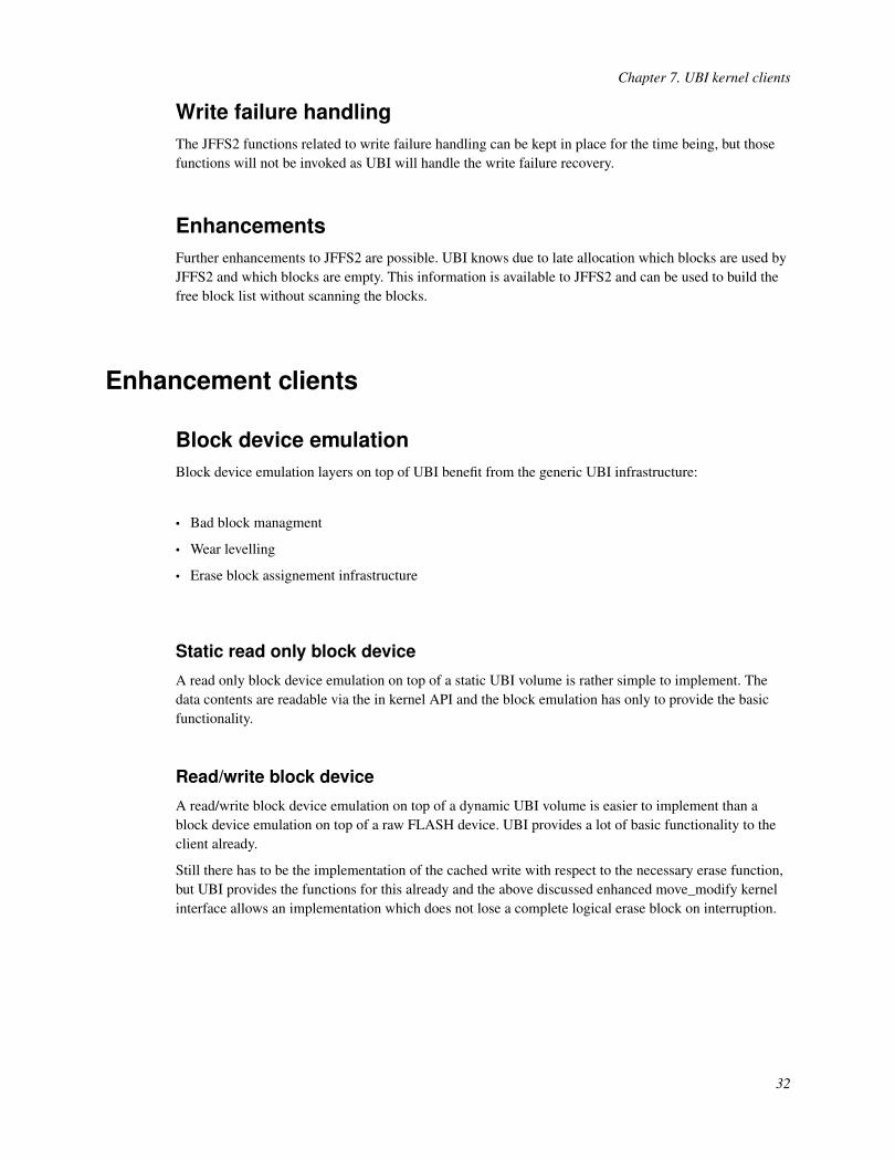
A read/write block device emulation on top of a dynamic UBI volume is easier to implement than ablock device emulation on top of a raw FLASH device. UBI provides a lot of basic functionality to theclient already.
Still there has to be the implementation of the cached write with respect to the necessary erase function,but UBI provides the functions for this already and the above discussed enhanced move_modify kernelinterface allows an implementation which does not lose a complete logical erase block on interruption.
32

Chapter 8. Booting with UBIThis chapter describes the the general considerations to be made when booting a UBI-aware system. Inparticular it describes the impacts of UBI on the boot loader design.
When processors are powered on, they need to be initialized and brought into a state where morecomplex software, like an operating system, can be executed. The environment used for boot-strapping ismostly very limited and its resources are at a location predetermined by the processor architecture.
In traditional embedded systems usually NOR FLASH was used to store the boot-strap code, whichneeds to be mapped to contiguous memory range. NAND FLASH does not provide automatically acontiguous memory range for the first couple of instructions needed for the boot-strap process. Instead aspecial hardware needs to be added as a macro on the chip itself, e.g. the NDFC used in the PowerPC440EP, an external solution using an FPGA, or exploiting vendor specific solutions like SamsungOneNAND or M-System DiskOnChip.
Important is to note, that even in a UBI-aware system, the FLASH erase block containing this initialboot-strap code, must not be moved, like UBI does with any other flash erase blocks. Particular careneeds to be taken when this memory is deleted, or updated, because when this is interrupted, the systemmight not be able to boot anymore. To overcome this limitation the hardware design must providewatchdog mechanisms used to switch to a different memory location if the predefined memory isaccidently invalid.
NOR FLASH systemThe erase-blocks containing the boot-strap code need to be fixed, by using a non-UBI partition. Thesystem design can reserve here as many blocks as needed for boot-loaders like U-Boot, Redboot orsimilar. The FLASH update of those special areas is to be implemented differently than the update of aUBI based volume.
Table 8-1. Partitioning for a NOR system
Partition Physical erase blocksBoot-strap code 0 - 4
UBI 5 - max. blocks
The erase blocks excluded from UBI are not due to wear-leveling or scrubbing. If bit-errors occur or theblocks need to be updated, the system must not be turned off. If the system should be able to recoverfrom power-loss or interruption, it must provide system specific hardware mechanisms with a watchdogand a method to use a redundant copy of the boot-code, stored at a different location.
To be able to load the operating system from a static UBI volume the code must contain a UBI scanningprocedure as well as a UBI loader.
NAND FLASH systemThe FLASH erase block used for storage of the boot-strap code is usually NAND erase block 0. This
33

Chapter 8. Booting with UBI
block is guaranteed to be a good block by the NAND chip vendors.
A PowerPC 440EP with a build in NDFC provides 4 Kbyte contignous memory for boot-strapping. Adevice using a Samsung OneNAND chip offers 2 KByte memory and a M-Systems DiskOn Chip comeswith 1 KByte. Some ARM chips have on-board flash usable for processor boot-strap. The sizes arevarying from 16 to 32 Kbyte, depending on the processor.
Because in NAND based systems contignous memory for the initial code is limited, complex boot-codeneeds to be split into two parts. Those parts are referred to as IPL (initial program loader) and SPL(secondary program loader). It is beneficial to store the SPL in a static UBI-volume, which can even beredundant, allowing a safe update procedure and gaining the advantages of UBI. The user does not needto make us his mind about wear-leveling, bad block handling and scrubbing for this code.
It is possible to scan a NAND chip for UBI data and do error correction using ECC in about 2 to 3 KByte.
Instead of using an SPL, the system designer may consider using an operating system image directly, ifhe is able to do the necessary system initialization in the IPL.
In this system NAND block 0 needs to be defined at a fixed location.
Table 8-2. Partitioning for a NAND system
Partition Physical erase blocksInitial Program Loader 0
UBI 1 - max. blocks
IPL and SPLWe assume that most NAND implementations will use a split of IPL and SPL. Instead of using an SPLwe think that some size restricted designs will choose to load the OS image directly. The followingexamples should illustrate how a systems with redundant SPL and OS images may be setup.
Example volume layoutThe example layout shows the fixed erase block 0. Block 0 contains redundant versions of the IPL,selected by a watchdog mechanism. The UBI volume numbering starts here at 2 used for the firstredundant copy of the SPL. The second copy of the SPL is stored in volume 3. Volume 4 and 5 are usedfor SPL configuration data like boot-parameter or platform description data (PDD). Volumes 6 and 7 areused for the operating system binary image. All of the listed UBI volumes are static. Subsequentvolumes e.g. 8, 9 and 10 can be used for file systems. Those would be dynamic UBI volumes.
34

Chapter 8. Booting with UBI
Figure 8-1. Example volume layout
IPL operations - Example: PPC44x using NANDWhen using a PowerPC 440EP with an NDFC, the IPL size is restricted to 4 Kbyte. Initially the NDFC isoperating in the so called AUTOREAD-mode presenting the 4 Kbyte IPL code at the memory rangefrom 0xfffff000 to 0xffffffff. The IPL needs to boot-strap itself either into iCache or into DRAM becausethe AUTOREAD-mode needs to be disabled for the UBI-scan and when loading the SPL/OS-image.
35
Chapter 8. Booting with UBI
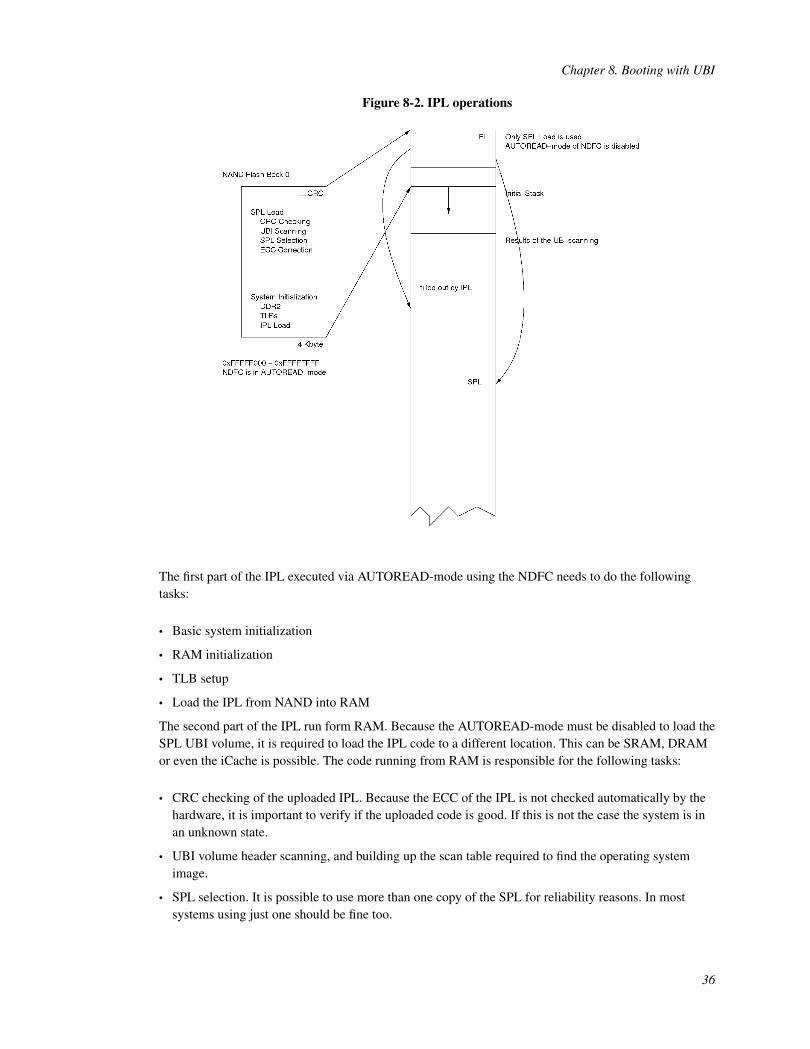
Figure 8-2. IPL operations
The first part of the IPL executed via AUTOREAD-mode using the NDFC needs to do the followingtasks:
• Basic system initialization
• RAM initialization
• TLB setup
• Load the IPL from NAND into RAM
The second part of the IPL run form RAM. Because the AUTOREAD-mode must be disabled to load theSPL UBI volume, it is required to load the IPL code to a different location. This can be SRAM, DRAMor even the iCache is possible. The code running from RAM is responsible for the following tasks:
• CRC checking of the uploaded IPL. Because the ECC of the IPL is not checked automatically by thehardware, it is important to verify if the uploaded code is good. If this is not the case the system is inan unknown state.
• UBI volume header scanning, and building up the scan table required to find the operating systemimage.
• SPL selection. It is possible to use more than one copy of the SPL for reliability reasons. In mostsystems using just one should be fine too.
36

Chapter 8. Booting with UBI
• Loading SPL with ECC correction. If the ECC needs to be corrected, the UBI layer in the OS musttake care that this erase block is copied to a new block and the ECC failure is corrected. Mosthardware, like the 440EP implementation can correct one bit failures and detect two bit failures. Thesystem design must ensure that bit flips are corrected as soon as possible to prevent a situation wherethe code required for booting becomes invalid.
Since the IPL has to scan the flash to find the UBI blocks of the SPL it makes sense to pass the scanninginformation to the SPL to save some boot-time.
UBI support in boot-loaderThe boot-loader must be extended to handle UBI managed FLASH devices. The implementation mightnot provide full fledged UBI support, but basic functionalities have to be implemented.
• Device scan
• Read volume contents
• Update volume contents (optional)
Device scanThe scan of an UBI device is necessary in the initial boot loader to be able to load the next stepboot-code or operating system using an UBI volume. The result of the initial scan result is recommendedto be passed to the SPL to speed up the boot-process.
The scan of an UBI device is either performed by a full FLASH scan or when available by analyzing aFLASH based erase block translation table. Since the FLASH based erase block table does not need toexist or be valid, a full scan is always be possible. This was one of the UBI design requirements.
A full scan reads the headers of all FLASH erase blocks and creates a list of the available UBI volumes.The scan can be performed in 3 steps. First each header is read into an RAM array and checked for theavailability of the UBI magic number and consistency of the header CRC. The number of erase blocksper volume is accounted. This information is used to create a table which contains the volume offsets inthe final load order table. This table is created in the last step of the scan. For each found volume theerase block numbers of the image parts is stored in load order.
To optimize the scanning time reading out the OOB area, for a system using NAND, can be omitted. Theinformation if the data is valid is concluded from the correctness of the data CRC.
Handling of FLASH based erase block translation tables is not described yet as the design of thismechanism in UBI is not done at the moment.
The result of the scan in the SPL or Initial boot loader can be stored in a RAM based structure which listsall found volumes, the number of used blocks per volume and the references to the logical blocks of eachvolume in load order.
37
Chapter 8. Booting with UBI
Scan result table
In an IPL/SPL implementation the information is generated by the IPL, because it needs it to load theSPL. The SPL can reuse the table to load e.g. different versions of the operating system image.
read volumesBoot-code support for reading UBI volumes can be restricted to static volumes to keep it as simple aspossible. Reading the raw contents of dynamic volumes is possible of course, but usage of the contentrequires detailed knowledge of its data structures.
The read support for static volumes is used to load binary images e.g. kernel, initrd or the boot-parameterdata blob from FLASH into RAM.
The read support should be aware of interrupted updates and block moving operations. In case of aninterrupted update the volume content can not be retrieved. In case of an interrupted block movingoperation the robustness mechanism described in the UBI design document apply.
write volumesWrite support for UBI volumes requires to implement following functionality:
• Bad block awareness
• Analyzing the layout volume
• Erase count preserving block erasure
• UBI aware writing of logical erase blocks
• UBI aware updating of static volumes
• Awareness about the reserved blocks
38