ubiqloud: a platform-as-a-service for the web of things
TRANSCRIPT

AALTO UNIVERSITYSchool of ScienceDepartment of Media Technology
Kalle Juhani Säilä
UbiQloud: A Platform-as-a-Service for theWeb of Things
Master’s ThesisHelsinki, June 25, 2012
Supervisor: Professor Petri Vuorimaa, D.Sc. (Tech.), Aalto UniversityInstructor: Markku Laine, M.Sc. (Tech.), Aalto University

AALTO UNIVERSITY ABSTRACT OFSchool of Science MASTER’S THESISDegree Programme of Computer Science and Engineering
Author: Kalle Juhani SäiläTitle:UbiQloud: A Platform-as-a-Service for the Web of Things
Date: June 25, 2012 Pages: xiii + 76Professorship: Media Technology Code: T-111Supervisor: Professor Petri Vuorimaa, D.Sc. (Tech.)Instructor: Markku Laine, M.Sc. (Tech.)
Over the years, the World Wide Web (Web) has evolved from a simplesystem for sharing static documents to a social and dynamic applicationplatform. In addition, the range of devices and input methods used tointeract with Web applications has increased. This evolution has openedup new possibilities for application development as data from other appli-cations and physical devices is now available for mashups through openAPIs. At the same time, however, the complexity of application develop-ment has increased and the technologies at the foundation of the Web failto meet the requirements for modern Web applications.
The main objective of this Thesis was to study how the development ofmodern Web applications can be facilitated leveraging third-party servicesand modern technologies. Furthermore, the study focused on designingand implementing a modern cloud-based platform, UbiQloud, offering awide range of essential services needed to develop social and location-awareWeb of Things applications with real-time communication capabilities.The platform was validated by developing two sample applications on topof it as well as by conducting a series of performance and stress tests.
The results show that it is possible to implement a scalable, high perfor-mance cloud-based platform that offers a wide range of services essentialfor modern Web application development and can be used with real ap-plications in real world settings.
Keywords: UbiQloud, server push, Web of Things, positioning,social media, cloud service, XMPP, WWW, Web
Language: English
ii
AALTO YLIOPISTO DIPLOMITYÖNPerustieteiden korkeakoulu TIIVISTELMÄTietotekniikan koulutusohjelma
Tekijä: Kalle Juhani SäiläTyön nimi:UbiQloud: Palvelualusta Esineiden Web -sovelluksille
Päiväys: 25. kesäkuuta 2012 Sivumäärä: xiii + 76Professuuri: Mediatekniikka Koodi: T-111Työn valvoja: Professori Petri Vuorimaa, TkTTyön ohjaaja: DI Markku Laine
Vuosien saatossa World Wide Web (Web) on kehittynyt pöytäkoneilla käy-tettävästä yksinkertaisesta dokumenttien jakojärjestelmästä sosiaaliseksija dynaamiseksi ohjelmistoalustaksi, jota käytetään monenlaisilla pääte-laitteilla eri yhteyksissä. Webin kehitys on luonut sovelluskehittäjille mah-dollisuuden uudenlaisten sovellusten kehittämiselle, joissa hyötykäytetääntietoa muista sovelluksista ja fyysisistä laitteista avointen rajapintojenkautta. Samanaikaisesti sovelluskehitys on muodostunut entistä haasta-vammaksi, koska Webin perustana toimivat teknologiat eivät enää pystyvastaamaan nykyaikaisten sovellusten vaatimuksiin.
Tämän diplomityön tarkoituksena oli selvittää, kuinka nykyaikaisten Web-sovellusten kehittämistä voitaisiin helpottaa kolmannen osapuolen palve-luiden ja uusien teknologioiden avulla. Lisäksi diplomityöhön sisältyi nyky-aikaisen pilvipohjaisen alustan, UbiQloudin, suunnittelu ja toteutus. Alus-tan tarkoituksena on tarjota sovelluskehittäjille yhdestä paikasta suurimäärä palveluita, joita tarvitaan reaaliaikaisten, sosiaalisten ja paikkatie-toisten Web of Things -sovellusten kehittämiseksi. Alusta validoitiin kah-den esimerkkisovelluksen avulla sekä suorittamalla joukko testejä alustansuorituskyvyn mittaamiseksi.
Tuloksien pohjalta voidaan sanoa, että on mahdollista toteuttaa skaalau-tuva ja suorituskykyinen pilvipohjainen alusta, joka tarjoaa suuren mää-rän nykyaikaisille Web-sovelluksille tärkeitä palveluita. Lisäksi esimerkki-sovellukset todistavat, että alusta soveltuu käytettäksi oikeiden sovellustenkanssa oikeassa ympäristössä.
Avainsanat: UbiQloud, push-viestit, esineiden Web, paikantaminen,sosiaalinen media, pilvipalvelu, XMPP, WWW, Web
Kieli: englanti
iii

Acknowledgments
I would like to thank the following persons:
M.Sc. Markku Laine at the Aalto University for his invaluable guidanceand support as the instructor of this Thesis. In addition to the formal in-structor duties, I would like to thank Markku for the countless laughs andinspiring work sessions that made the work feel like something else entirely.
Professor Petri Vuorimaa at the Aalto University for giving me the op-portunity to work with inspiring topics close to my heart as well as patientlyguiding and supervising my Thesis.
MA in New Media Petri Saarikko, my closest co-worker and a friend,at the Aalto University for making every work day interesting and different.I would also like to thank Petri for all the insight and knowledge of graphicsand service design as well as for both the serious and hilarious conversationson and off work.
Friends and family for their invaluable help and support through out theyears. Especially I would like to thank my mum, Heidi Nyman, and aunt,Christel Nyman, for encouraging me to pursuit my dreams. In addition, Iwould like to thank my late father, Pertti Säilä, who would have been soproud of me.
Inka-Maria Karhunsuo, my beloved wife and best friend, who makes mewhole and has pushed me forward during the years. I love you!
Nooa Säilä, my little baby boy, whose smile continuously makes my worlda better place. I grow as a man as I watch him grow to a little human being.
Helsinki, June 25th, 2012
Kalle Säilä[email protected]
iv

Abbreviations and Acronyms
API Application Programming InterfaceAWS Amazon Web ServicesBOSH Bidirectional-streams Over Synchronous
HTTPCoAP Constrained Application ProtocolCSS Cascading Style SheetsCSV Comma Separated ValuesEAN International Article Number, formerly Euro-
pean Article NumberGPS Global Positioning SystemGSM Global System for Mobile CommunicationsGUPSS Gateway-Based Ubiquitous Platform for
Smart SpaceHMAC Hash-based Message Authentication CodeHTML Hypertext Markup LanguageHTTP Hypertext Transfer ProtocolIaaS Infrastructure-as-a-ServiceIM Instant MessagingIoT Internet of ThingsIP Internet ProtocolISBN International Standard Book NumberJID Jabber IDJSON JavaScript Object NotationLAN Local Area NetworkMB2 Magic Broker 2MIDE Multidisciplinary Institute of Digitalisation
and EnergyNFC Near Field CommunicationOS Operating SystemPaaS Platform-as-a-Service
v

RDBMS Relational Database Management SystemREST Representational State TransferRFID Radio Frequency IdentificationRPC Remote Procedure CallRSS Really Simple SyndicationSaaS Software-as-a-ServiceTCP Transmission Control ProtocolUDP User Datagram ProtocolUHF Ultra-High FrequencyUI User InterfaceUPC Universal Product CodeURI Unified Resource IdentifierUTC Coordinated Universal TimeVoIP Voice over IPW3C World Wide Web ConsortiumWeb World Wide WebWLAN Wireless Local Area NetworkWoT Web of ThingsWSN Wireless Sensor NetworkWWW World Wide WebXEP XMPP Extension ProtocolXML Extensible Markup LanguageXMPP Extensible Messaging and Presence Protocol,
formerly Jabber
vi
Contents
Abbreviations and Acronyms v
1 Introduction 1
1.1 Organization of the Thesis . . . . . . . . . . . . . . . . . . . . 3
2 Background 4
2.1 Server Push . . . . . . . . . . . . . . . . . . . . . . . . . . . . 4
2.1.1 Publish/Subscribe . . . . . . . . . . . . . . . . . . . . 5
2.1.2 XMPP . . . . . . . . . . . . . . . . . . . . . . . . . . . 6
2.1.3 WebSocket . . . . . . . . . . . . . . . . . . . . . . . . . 8
2.2 Internet of Things / Web of Things . . . . . . . . . . . . . . . 9
2.2.1 Smart Object . . . . . . . . . . . . . . . . . . . . . . . 10
2.2.2 Smart Space . . . . . . . . . . . . . . . . . . . . . . . . 10
2.2.3 Representational State Transfer . . . . . . . . . . . . . 11
2.3 Positioning . . . . . . . . . . . . . . . . . . . . . . . . . . . . 12
2.4 Social Media . . . . . . . . . . . . . . . . . . . . . . . . . . . . 14
2.4.1 Social Login . . . . . . . . . . . . . . . . . . . . . . . . 15
2.5 Cloud Computing . . . . . . . . . . . . . . . . . . . . . . . . . 16
3 State-of-the-Art 19
3.1 Related Research Activities . . . . . . . . . . . . . . . . . . . 19
3.2 Existing Services . . . . . . . . . . . . . . . . . . . . . . . . . 20
3.2.1 Server Push Services . . . . . . . . . . . . . . . . . . . 20
vii

3.2.2 Web of Things Services . . . . . . . . . . . . . . . . . . 22
3.2.3 Positioning Services . . . . . . . . . . . . . . . . . . . . 23
3.2.4 Social Media Gateways . . . . . . . . . . . . . . . . . . 24
4 Research Aims 26
4.1 Research Objectives and Scope . . . . . . . . . . . . . . . . . 26
4.1.1 4D-Space Project . . . . . . . . . . . . . . . . . . . . . 27
4.2 Research Questions . . . . . . . . . . . . . . . . . . . . . . . . 27
4.3 Research Methods . . . . . . . . . . . . . . . . . . . . . . . . . 28
5 Platform Requirements 29
5.1 Terminals and Devices . . . . . . . . . . . . . . . . . . . . . . 29
5.2 Users . . . . . . . . . . . . . . . . . . . . . . . . . . . . . . . . 30
5.3 Objects . . . . . . . . . . . . . . . . . . . . . . . . . . . . . . 32
5.4 Verification of the Requirements . . . . . . . . . . . . . . . . . 32
5.5 Requirements . . . . . . . . . . . . . . . . . . . . . . . . . . . 32
5.5.1 R1: RESTful API . . . . . . . . . . . . . . . . . . . . . 34
5.5.2 R2: Server Push . . . . . . . . . . . . . . . . . . . . . 34
5.5.3 R3: User Profiles . . . . . . . . . . . . . . . . . . . . . 34
5.5.4 R4: Positioning . . . . . . . . . . . . . . . . . . . . . . 35
5.5.5 R5: Object Recognition . . . . . . . . . . . . . . . . . 35
5.5.6 R6: Sensor Integration . . . . . . . . . . . . . . . . . . 35
5.5.7 R7: Information Aggregation . . . . . . . . . . . . . . 36
5.5.8 R8: Social Sharing . . . . . . . . . . . . . . . . . . . . 36
6 Implementation 37
6.1 UbiQloud Overview . . . . . . . . . . . . . . . . . . . . . . . . 37
6.2 Server Components . . . . . . . . . . . . . . . . . . . . . . . . 39
6.3 UbiQloud Application . . . . . . . . . . . . . . . . . . . . . . 41
6.3.1 Recognize Module . . . . . . . . . . . . . . . . . . . . . 42
6.3.2 Locate Module . . . . . . . . . . . . . . . . . . . . . . 43
viii

6.3.3 Connect Module . . . . . . . . . . . . . . . . . . . . . 44
6.3.4 Share Module . . . . . . . . . . . . . . . . . . . . . . . 45
6.4 Communication with UbiQloud . . . . . . . . . . . . . . . . . 45
6.4.1 RESTful API . . . . . . . . . . . . . . . . . . . . . . . 46
6.4.2 Server Push Interfaces . . . . . . . . . . . . . . . . . . 48
6.4.3 Smart Gateway . . . . . . . . . . . . . . . . . . . . . . 50
6.4.4 Social Gateway . . . . . . . . . . . . . . . . . . . . . . 51
7 Sample Applications 53
7.1 Retail Context: FeedThroat . . . . . . . . . . . . . . . . . . . 53
7.1.1 Integration to UbiQloud . . . . . . . . . . . . . . . . . 55
7.1.2 User Tests . . . . . . . . . . . . . . . . . . . . . . . . . 56
7.2 Positioning Context: InView . . . . . . . . . . . . . . . . . . . 57
7.2.1 Integration to UbiQloud . . . . . . . . . . . . . . . . . 58
7.3 Conclusions . . . . . . . . . . . . . . . . . . . . . . . . . . . . 58
8 Testing and Evaluation 60
8.1 Setup . . . . . . . . . . . . . . . . . . . . . . . . . . . . . . . . 60
8.2 Tools . . . . . . . . . . . . . . . . . . . . . . . . . . . . . . . . 61
8.3 Testing the Client Interface . . . . . . . . . . . . . . . . . . . 63
8.4 Testing the Sensor Interface . . . . . . . . . . . . . . . . . . . 64
8.5 Evaluation . . . . . . . . . . . . . . . . . . . . . . . . . . . . . 65
9 Conclusions 67
9.1 Research Objectives Revisited . . . . . . . . . . . . . . . . . . 67
9.2 Main Contributions . . . . . . . . . . . . . . . . . . . . . . . . 67
9.3 Results . . . . . . . . . . . . . . . . . . . . . . . . . . . . . . . 68
9.4 Future Work . . . . . . . . . . . . . . . . . . . . . . . . . . . . 69
ix
List of Tables
5.1 Requirements for the platform. . . . . . . . . . . . . . . . . . 33
6.1 UbiQloud modules. . . . . . . . . . . . . . . . . . . . . . . . . 42
x

List of Figures
1.1 Service categories of the designed platform. . . . . . . . . . . . 3
2.1 Comparison between a push-based and pull-based interactionmodel. . . . . . . . . . . . . . . . . . . . . . . . . . . . . . . . 5
2.2 The publish/subscribe interaction model. . . . . . . . . . . . . 6
2.3 The XMPP-based client/server interaction model. . . . . . . . 7
2.4 The WebSocket-based client/server interaction model. . . . . . 8
2.5 A Smart Gateway as mediator between an RFID reader com-municating with TCP protocol and a Web application. . . . . 10
2.6 Terminal-based and network-based positioning systems. . . . . 13
2.7 Social Login steps with Facebook: authentication and appli-cation authorization. . . . . . . . . . . . . . . . . . . . . . . . 16
2.8 Cloud computing models. . . . . . . . . . . . . . . . . . . . . 17
3.1 Facebook chat accessed through the official Facebook iPhoneapplication and in the iChat desktop application. . . . . . . . 21
3.2 Example of extending an existing system with an RFID mid-dleware. . . . . . . . . . . . . . . . . . . . . . . . . . . . . . . 22
3.3 Position fingerprints on top of an indoor map. . . . . . . . . . 24
3.4 Janrain Engage Social Login widget. . . . . . . . . . . . . . . 25
5.1 Different display types. . . . . . . . . . . . . . . . . . . . . . . 30
6.1 UbiQloud communication architecture. . . . . . . . . . . . . . 38
6.2 Components of the UbiQloud platform. . . . . . . . . . . . . . 40
6.3 Relations between the UbiQloud modules and requirements. . 43
xi

6.4 Example of using the UbiQloud APIs for pushing the locationinformation of a user. . . . . . . . . . . . . . . . . . . . . . . . 44
6.5 Secure communication with the UbiQloud RESTful API. . . . 47
6.6 Six steps for Social Login through UbiQloud. . . . . . . . . . . 52
7.1 FeedThroat UI views in iOS application. . . . . . . . . . . . . 54
7.2 FeedThroat retailer view in the Web application. . . . . . . . . 55
7.3 InView UI views in Android and iOS devices. . . . . . . . . . . 57
8.1 Benchmark results for a single request response time againstthe client interface of the single and scaled UbiQloud with 50concurrent users and 10000 requests. . . . . . . . . . . . . . . 63
8.2 Benchmark results for a single request response time againstthe sensor interface of the single and scaled UbiQloud with 50concurrent users and 10000 requests. . . . . . . . . . . . . . . 64
8.3 Requests per second served during the tests. . . . . . . . . . . 66
xii

Listings
2.1 Minimal message stanza. . . . . . . . . . . . . . . . . . . . . . 7
2.2 Message stanza with all attributes. . . . . . . . . . . . . . . . 7
2.3 Initializing a WebSocket object with JavaScript. . . . . . . . . 9
2.4 Example of a REST URI. . . . . . . . . . . . . . . . . . . . . 12
2.5 Example of the JSON representation of a resource. . . . . . . 12
2.6 Example of the XML representation of a resource. . . . . . . . 12
2.7 Example of using the W3C Geolocation API with JavaScript. 14
6.1 Example of the JSON representation of a resource . . . . . . . 46
6.2 Example of the XML representation of a resource . . . . . . . 46
6.3 Example of an XMPP publish/subscribe message. . . . . . . . 50
6.4 Example of embedding the UbiQloud Social Login widget. . . 52
8.1 Example of an Apache Bench script. . . . . . . . . . . . . . . 62
8.2 Example of an Apache Bench console output. . . . . . . . . . 62
xiii

Chapter 1
Introduction
Over the years, the World Wide Web (Web) has evolved from a simple systemfor sharing static documents to a social and dynamic application platform [1].According to Mikkonen and Taivalsaari [2], Web applications have numerousbenefits in comparison to binary end-user software, such as instant, world-wide deployment; end-user independent upgrades; and platform independentaccess to data.
As the Web has evolved, different terms have been introduced to describe thecurrent and future state of the Web. Murugesan [3] has divided the Web evo-lution into four distinct generations, as follows: Information-centered (legacy,Web 1.0), People-centered (current, Web 2.0), Machine-centered (upcoming,Web 3.0), and Agent-centered (future, Web 4.0). At the beginning (Web1.0), the Web was a platform for sharing static documents. The currentPeople-centered Web (Web 2.0) emphasizes Social Media and has somewhatmigrated the content providers and the content consumers to a single groupof Web users. The next generation (Web 3.0) emphasizes machine to ma-chine communication and makes the Web more context-aware and collabo-rative platform through data and device integration (i.e., the Web of Things,WoT ). The Agent-centered generation sees the Web evolving to an ubiquitousenvironment seamlessly integrating both human and machine intelligence.
In addition to the evolution of the Web, the ways of interacting with Webapplications have also changed drastically. Traditionally, the Web was ac-cessed from a personal computer via a Web browser and the applications werecontrolled through standard input devices, such as a keyboard or a mouse.Nowadays, the Web can be accessed with numerous ways with an increasingrange of different devices (e.g., smartphones and tablets) and input methods,such as touch. These changes have introduced new requirements as well as
1
CHAPTER 1. INTRODUCTION 2
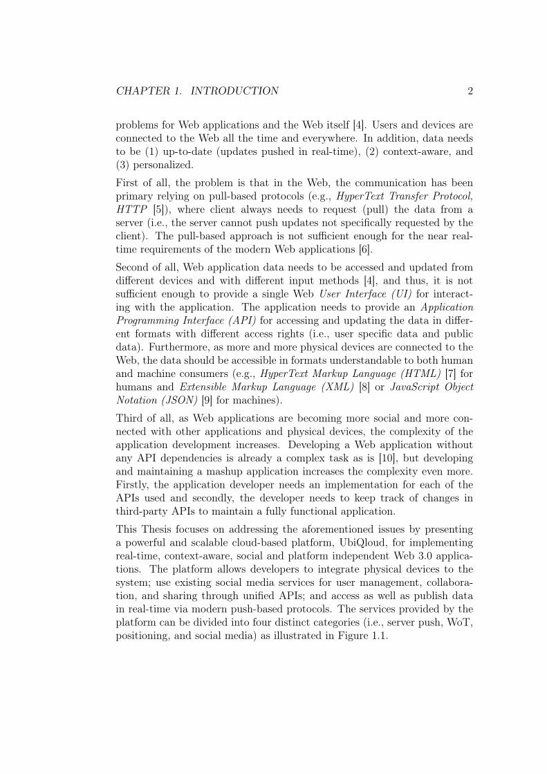
problems for Web applications and the Web itself [4]. Users and devices areconnected to the Web all the time and everywhere. In addition, data needsto be (1) up-to-date (updates pushed in real-time), (2) context-aware, and(3) personalized.
First of all, the problem is that in the Web, the communication has beenprimary relying on pull-based protocols (e.g., HyperText Transfer Protocol,HTTP [5]), where client always needs to request (pull) the data from aserver (i.e., the server cannot push updates not specifically requested by theclient). The pull-based approach is not sufficient enough for the near real-time requirements of the modern Web applications [6].
Second of all, Web application data needs to be accessed and updated fromdifferent devices and with different input methods [4], and thus, it is notsufficient enough to provide a single Web User Interface (UI) for interact-ing with the application. The application needs to provide an ApplicationProgramming Interface (API) for accessing and updating the data in differ-ent formats with different access rights (i.e., user specific data and publicdata). Furthermore, as more and more physical devices are connected to theWeb, the data should be accessible in formats understandable to both humanand machine consumers (e.g., HyperText Markup Language (HTML) [7] forhumans and Extensible Markup Language (XML) [8] or JavaScript ObjectNotation (JSON) [9] for machines).
Third of all, as Web applications are becoming more social and more con-nected with other applications and physical devices, the complexity of theapplication development increases. Developing a Web application withoutany API dependencies is already a complex task as is [10], but developingand maintaining a mashup application increases the complexity even more.Firstly, the application developer needs an implementation for each of theAPIs used and secondly, the developer needs to keep track of changes inthird-party APIs to maintain a fully functional application.
This Thesis focuses on addressing the aforementioned issues by presentinga powerful and scalable cloud-based platform, UbiQloud, for implementingreal-time, context-aware, social and platform independent Web 3.0 applica-tions. The platform allows developers to integrate physical devices to thesystem; use existing social media services for user management, collabora-tion, and sharing through unified APIs; and access as well as publish datain real-time via modern push-based protocols. The services provided by theplatform can be divided into four distinct categories (i.e., server push, WoT,positioning, and social media) as illustrated in Figure 1.1.

CHAPTER 1. INTRODUCTION 3
Figure 1.1: Service categories of the designed platform.
1.1 Organization of the Thesis
The rest of the Thesis is organized as follows. Chapter 2 covers the technicaland conceptual background information relevant to the topic at hand. InChapter 3, a state-of-the-art review of related research and existing imple-mentations is presented. Next, the research aims, questions, scope, and set-tings are introduced in Chapter 4. Then, the requirements for the platformare presented in Chapter 5. Chapter 6 covers the proof-of-concept imple-mentation of the platform, and Chapter 7 gives an overview of the sampleapplications developed on top of the platform. In Chapter 8, the evalua-tion tests are presented, and the results are analyzed and discussed. Finally,Chapter 9 concludes the Thesis.

Chapter 2
Background
In this chapter, an introduction to the concepts and technologies relevant tothis Thesis is given. The first section describes the basics of server push andgives an overview of modern server push technologies, including XMPP andWebSocket. Then, the concept of the Web of Things (WoT) is presentedin detail, followed by the description of technologies and problems in posi-tioning. Next, the social media and Social Login are covered, and lastly thebasics of cloud computing models are introduced.
2.1 Server Push
HyperText Transfer Protocol (HTTP) [5], which is the basis of communicationon the Web, is based on the request/response paradigm. This means thatall HTTP-based communication is based on request/response pairs alwaysinitiated by the client. After each response, the connection is closed and anew request must be made in order the receive new data. The server needs towait that the client requests new data, before it can be sent to the client. Asthe Web has evolved from a simple document sharing system to a dynamicapplication platform, the pull-based technique is no longer sufficient to fulfillthe requirements of modern Web applications [6].
To overcome the real-time limitations of HTTP, servers need to be able topush data to the clients. Server push is not a protocol like HTTP but aparadigm for techniques allowing robust communication between clients andservers. Regardless of the implementation, the common factor in all serverpush systems is the ability to push changes through permanent channel fromthe server to the client as soon as the changes occur on the server [6]. In
4

CHAPTER 2. BACKGROUND 5
other words, server push allows clients to utilize real-time data channels froma server to a client in parallel with the traditional information pull. Figure 2.1demonstrates the difference between a push-based and a pull-based system.Even though, the figure shows two different clients, they could also be thesame client utilizing both techniques. In addition, the permanent connectionbetween client and server can be either one-way or two-way channel (i.e.,data can be sent only from server to client or both ways).
Client Client
Server Push Client Pull
Server
Request
Response
Request
Response
Initialize Channel
Data
Data Data
Permanent Connection
Figure 2.1: Comparison between a push-based and pull-based interactionmodel.
2.1.1 Publish/Subscribe
Publish/subscribe is an architecture in which the information is collectedfrom a number of sources (publishers) and delivered to a number of interestedconsumers (subscribers) in an anonymous and asynchronous manner. In apublish/subscribe system, a publisher(s) publishes data in a node(s) and thedata is then pushed to all subscribers of that node, if any. A publisher doesnot need to know the identities of the subscribers or wait for subscribersrequests. The data is simply multicasted from a publisher to a number ofsubscribers in real-time. [11] Figure 2.2 illustrates the interaction modelbetween publishers and subscribers in a publish/subscribe system. In thefigure, there are two publishers pushing weather information to four nodes.One of the nodes is used by both of the publishers and the other three isused by a one publisher only. There are also three clients subscribed to anumber of nodes. One of the nodes (Helsinki Weather) has no subscribers,but new data is still pushed to it because the publisher is not aware of thesubscribers.

CHAPTER 2. BACKGROUND 6
Figure 2.2: The publish/subscribe interaction model.
2.1.2 XMPP
Extensible Messaging and Presence Protocol (XMPP) [12] is an XML-based,application-level protocol for exchanging structured data between any net-work entities in near real-time. XMPP was originally developed under thename Jabber in the Jabber open-source community for instant messaging(IM) and presence applications, such as chats with authenticated users [13].Later, the core of the Jabber protocol was revised and formalized by theInternet Engineering Task Force (IETF)1, and published under its currentname XMPP in their Request for Comments (RFC) series as RFC 6120 [14]and RFC 6121 [15]. In addition, the XMPP Standards Foundation (XSF)2
has developed and published over 300 XMPP Extension Protocols (XEPs)3
to support a wide variety of application scenarios, such as XEP-0206: XMPPOver BOSH, which is an HTTP binding for XMPP communications [16] andXEP-0060: Publish-Subscribe [17] for publish/subscribe systems.
Similar to the Web, also XMPP is based on a decentralized client/(serverarchitecture. When an XMPP client wants to start a session with an XMPPserver, it opens an XML stream over a long-lived connection (e.g., Trans-
1Internet Engineering Task Force, http://www.ietf.org/2XMPP Standards Foundation, http://xmpp.org/about-xmpp/xsf/3XMPP Extension Protocols, http://xmpp.org/xmpp-protocols/xmpp-extensions/

CHAPTER 2. BACKGROUND 7
mission Control Protocol, TCP [18]) to the server. Next, the server opensanother XML stream to the client, resulting in two XML streams over asingle TCP socket, one in each direction. Figure 2.3 illustrates the XMPPinteraction model between the client and the server.
Figure 2.3: The XMPP-based client/server interaction model.
After the connections have been established, each entity can asynchronouslyexchange an unbound number of special XML snippets over the streams.These special XML snippets, called XML stanzas, define the basic units ofcommunication in XMPP and are as follows: message, presence, and iq(Info/Query). The Message Stanza, which is the basis of client to clientmessage transfer in XMPP, consists of a root element called <message> anda child element called <body>, the latter being a wrapper for the actualmessage payload. In addition, the root element contains 1-5 attributes thatare: to (mandatory), from, id, type, and xml:lang. Listings 1 and 2 showexamples of an XMPP message with a minimum and maximum amount ofattributes.<message to="{username}@{domain}">
<body>{payload}</body></message >
Listing 2.1: Minimal message stanza.
<message to="{username}@{domain }/{ resource}"from="{username}@{domain }/{ resource}"id="{messageId}"type="{chat|error|groupchat|headline|normal}"xml:lang="{xmlLang}"><body>{payload}</body>
</message >
Listing 2.2: Message stanza with all attributes.
CHAPTER 2. BACKGROUND 8
Even though XMPP provides a rich set of features and is a widely usedprotocol for real-time communication, it is hardly used on the traditionalWeb environment. There is two main reasons for this: (1) Web browsers donot provide native XMPP support and (2) regular XMPP communication isusually blocked by firewalls and proxies. Nevertheless, XMPP can be used inthe Web with push techniques (e.g., BOSH [19]) supported by Web browsers.
2.1.3 WebSocket
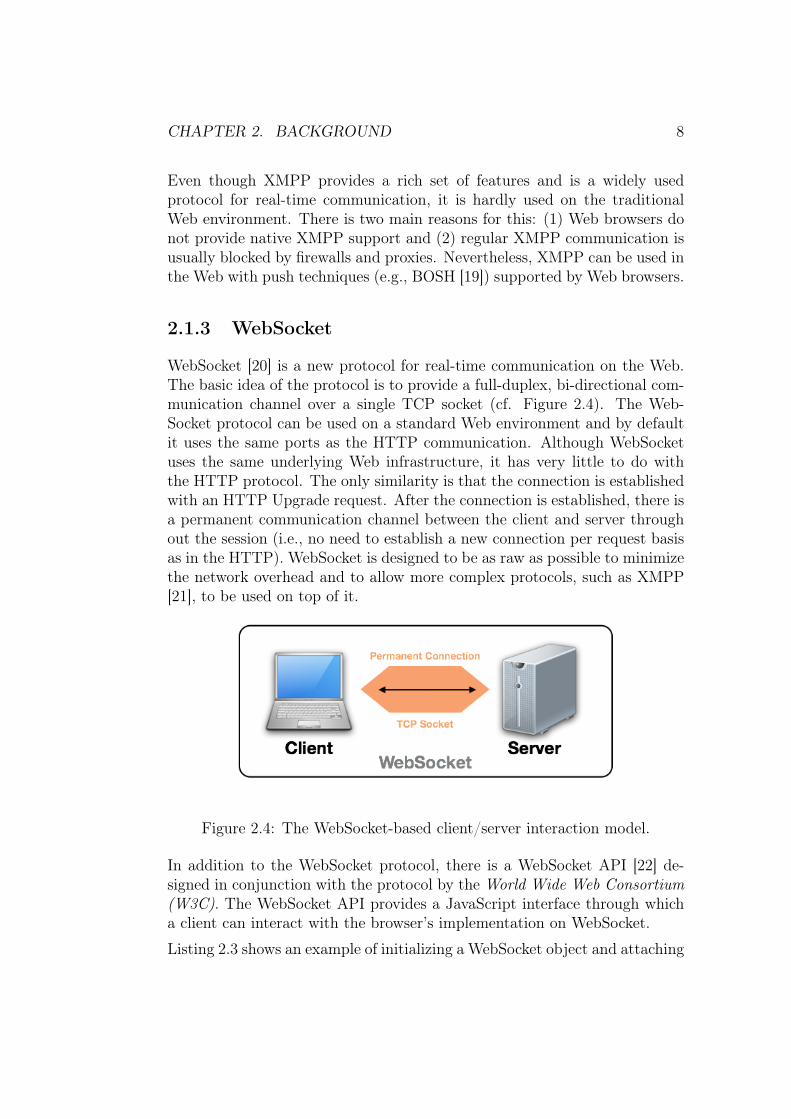
WebSocket [20] is a new protocol for real-time communication on the Web.The basic idea of the protocol is to provide a full-duplex, bi-directional com-munication channel over a single TCP socket (cf. Figure 2.4). The Web-Socket protocol can be used on a standard Web environment and by defaultit uses the same ports as the HTTP communication. Although WebSocketuses the same underlying Web infrastructure, it has very little to do withthe HTTP protocol. The only similarity is that the connection is establishedwith an HTTP Upgrade request. After the connection is established, there isa permanent communication channel between the client and server throughout the session (i.e., no need to establish a new connection per request basisas in the HTTP). WebSocket is designed to be as raw as possible to minimizethe network overhead and to allow more complex protocols, such as XMPP[21], to be used on top of it.
Figure 2.4: The WebSocket-based client/server interaction model.
In addition to the WebSocket protocol, there is a WebSocket API [22] de-signed in conjunction with the protocol by the World Wide Web Consortium(W3C). The WebSocket API provides a JavaScript interface through whicha client can interact with the browser’s implementation on WebSocket.
Listing 2.3 shows an example of initializing a WebSocket object and attaching

CHAPTER 2. BACKGROUND 9
event listeners to it. On the first line, the WebSocket object is initializedwith two parameters: (1) the URL of the connection endpoint, and (2) theprotocol (e.g., XMPP) used on top of the WebSocket connection. The URLformat is otherwise similar to HTTP, but it uses ws(s) instead of http(s)as the URL schema. The protocol parameter is optional, but can be used forexample in the server side to only accept connections using certain protocols.The rest of the example shows how to listen when the connection is opened,an error has occurred, or a message is received. Although the interface isdesigned for JavaScript, it can be implemented in other languages as well.var socket= new WebSocket("ws:// example.com", "xmpp");socket.onopen = function () {
alert("WebSocket Open!");};socket.onerror = function () {
alert("WebSocket Error!");};socket.onmessage = function (data) {
alert("WebSocket Message: " + data);};
Listing 2.3: Initializing a WebSocket object with JavaScript.
2.2 Internet of Things / Web of Things
According to Krannenburg [23], the Internet of Things (IoT) is an informa-tion architecture that extracts data from a network of devices and objects.On the other hand, IoT semantically is
"a world-wide network of interconnected objects uniquely addressable, basedon standard communication protocols." [24]
In short, IoT is a goal in which things — that is, physical objects or devices— constitute a network capable of communicating and interacting with eachother.
The Web of Things (WoT) can be viewed as a step towards reaching theInternet of Things vision and it basically means using the Web and Webtechnologies as means of connecting smart objects with the existing Web en-vironment [25]. Using Web standards to interconnect objects raises the prob-lem that in order to establish a connection, the object needs to understandthese standards. In the future, it is possible that most smart objects have

CHAPTER 2. BACKGROUND 10
an embedded web server, but for constrained objects we need a mediator,referred as a Smart Gateway [25], that is capable of communicating with theobject through proprietary/non-Web protocols and with the outside worldthrough Web-based protocols. Figure 2.5 demonstrates a situation in whichan Radio Frequency Identification (RFID) reader capable of communicationvia TCP is exposed to a Web application through a Smart Gateway.
Smart Gateway
RFID Reader Web Application
TCP HTTP
Figure 2.5: A Smart Gateway as mediator between an RFID reader commu-nicating with TCP protocol and a Web application.
2.2.1 Smart Object
Kortuem et al. [26] define a Smart Object as autonomous object that pos-sesses sensing, processing, and networking capabilities. On the other hand,a Smart Object can be considered as an object with a unique addressingschema capable of interacting and cooperating with each other [27]. Basedon these definitions, a Smart Object can be something as simple as a plainobject equipped with a RFID tag or something ’smarter’, such as a WirelessSensor Network (WSN), an embedded device, or a smartphone. All in all,the key thing is that the object can be uniquely identified and is capable ofautonomous interaction with other objects through a medium, such as theWeb.
2.2.2 Smart Space
According to Kawashima et al. [28], a Smart Space is a physical environmentequipped with sensing devices and actuation devices for contextual informa-tion collecting and context-aware responses. In general, a Smart Space isa space capable of autonomous, context-aware actions based on conditionevents generated by interconnected Smart Objects. For example, a smarthome could autonomously adjust lightning and heating based on weather

CHAPTER 2. BACKGROUND 11
conditions (e.g., summer day or winter night), or a car could adjust seatsand mirrors based on the driver identified by the car key.
2.2.3 Representational State Transfer
In order to connect physical objects as part of the Web, there needs tobe a way to represent and access these objects on the Web environment.One viable method [29] is to utilize a concept called Representational StateTransfer (REST) [30]. REST is a client/server architecture, in which a servercontains resources with unique identifiers. When a client requests a resourcefrom the server, the server responds with a representation of that resource.When the client moves from one representation to another, it also moves toa different state. The REST architectural style is based on six principles asfollows:
Uniform InterfaceImplementations are decoupled from the services they provide,
Client/ServerThere is a clear separation (i.e., uniform interface) between clients andservers,
StatelessNo client context is stored on the server,
CacheResponses must be labeled as cacheable or non-cacheable,
Layered SystemA client cannot tell whether it is connected to the end server or to anintermediary, and
Code-On-Demand (Optional)Servers are able to extend client functionality by transferring executablecode (e.g., JavaScript).
HTTP-based Web services that follow the principles of REST (potentiallyexcluding the Code-On-Demand constraint) are referred as RESTful Webservices. In RESTful Web services, all resources are identified with a UnifiedResource Identifier (URI) and accessed with common HTTP methods GET,POST, PUT, and DELETE.

CHAPTER 2. BACKGROUND 12
• GET is for retrieving a resource,
• POST is for creating a resource without existing identifier,
• PUT is for creating or modifying a resource with known identifier, and
• DELETE is for removing a resource.
A representation of a resource can vary based on the request (e.g., HTML fora Web browser and JSON for a server). For example, consider a Smart Spaceenvironment where users can control lamps through a RESTful interface.Each lamp is identified with an unique URI as follows:
http:// example.com/lamp/{ identifier}
Listing 2.4: Example of a REST URI.
The {identfier} is a unique property that distinguishes one lamp from an-other. So executing the following request:
HTTP GET: http://example.com/lamp/3
could result the following response in JSON:{"lamp" :
{"id" : 3,"on" : true}
}
Listing 2.5: Example of the JSON representation of a resource.
or in XML:<lamp>
<id>3</id><on>true</on>
</lamp>
Listing 2.6: Example of the XML representation of a resource.
2.3 Positioning
Positioning objects can be achieved with a wide variety of technologies, in-cluding Global Positioning System (GPS), Global System for Mobile Com-munications (GSM), Wireless Local Area Network (WLAN), and Bluetooth.

CHAPTER 2. BACKGROUND 13
The accuracy of each technology is highly dependable of the environment itis used and there is no single technology capable of accurate positioning bothindoors and outdoors. For example, GPS is capable of positioning objectswith a 10 meter accuracy most of the time outdoors, but is almost unusableindoors because it requires a line of sight to the satellites. [31]
Figure 2.6: Terminal-based and network-based positioning systems.
Positioning systems can be divided into two categories [31], Terminal-basedsystems and Network-based systems, as illustrated in Figure 2.6. In theTerminal-based systems, the location is calculated on the terminal (e.g.,smartphone) itself by using radio measurements and predefined antenna lo-cations (e.g., GPS satellite or WLAN base stations). The Network-basedpositioning systems, on the other hand, use a dedicated positioning serverattached to a network of antennas to calculate the terminal location. Thelatter is usually more accurate since the positioning server possesses morefine grained data of antennas. However, the solution does not scale well,because it relies on a fixed network of antennas.
While outdoor positioning is achieved relatively easy with GPS, indoor po-sitioning is much harder in general. The biggest issue in indoor positioningis usually the physical facility because these facilities often contain placeshard or impossible to detect using positioning technologies (e.g., no line ofsight, reflecting surfaces, and thick walls). [32] These obstacles can be cir-cumvented by installing enough hardware, but it is often too expensive andthe solution is tied to a particular location. At the moment, the most accu-

CHAPTER 2. BACKGROUND 14
rate indoor positioning systems (e.g., Skyhook4) use a hybrid approach bycombining multiple positioning technologies.
To ease the development of location-aware applications, W3C has proposeda standard [33] for a Geolocation API. The idea is to provide a standardizedinterface for developers to access location data. W3C does not guarantee theaccuracy of the location data gained through the API, since the device imple-menting the API is responsible for providing the data, and the technologiesfor gaining location data vary as stated above. The interface itself is quitesimple. It extends the Navigator object with a geolocation attribute, whichin turns implements the Geolocation interface that has methods for gaining acurrent position, watching position changes, and canceling a watch. Listing2.7 illustrates the use of the Geolocation API with JavaScript. In the exam-ple, two location related functions are executed at application startup. First,the current location is determined, and second, a listener that continuouslywatches the position is initialized.window.onload = function () {
var geoprovider = navigator.geolocation;geoprovider.getCurrentPosition(function(position) {
var lat = position.coords.latitude;var lon = position.coords.longitude;alert("Started from location: " + lat + " " + lon);
});
geoprovider.watchPosition(function(position) {var lat = position.coords.latitude;var lon = position.coords.longitude;alert("Current location: " + lat + " " + lon);
});};
Listing 2.7: Example of using the W3C Geolocation API with JavaScript.
2.4 Social Media
Mayfield [34] describes social media as a group of online media sharing similarcharacteristics, such as participation, conversation, and community. Basedon the characteristics, he has divided the social media into six distinct groupsas follows: social networks, blogs, wikis, podcasts, forums, and content com-munities. As described in Chapter 1, the current phase (Web 2.0) in theWeb evolution is People-centric and social media is one massive example of
4Skyhook, http://www.skyhookwireless.com/

CHAPTER 2. BACKGROUND 15
that (e.g., Facebook had 526 million active daily users on average in March20125). In general, social media has provided the ability for the content con-sumers to become content providers on the Web and allowed users to buildthemselves a digital identity that can be used in the digital world.
2.4.1 Social Login
Identifying users is a vital part of social media. As social media has becamesuch a popular phenomena, the number of social media applications andsocial networks has increased drastically [35]. Using different credentials inevery social service is a major problem for both the users and developers ofsocial Web applications. From a user’s point of view, it is tedious to managemultiple different user accounts that often leads to security risks becausesame passwords are used in many services. From a developer’s point of view,creating a new social network has became harder, since users are not willingto create yet another user profile. [36]
The problem of managing multiple user accounts has inspired a number ofsolutions to reduce the need of creating a new account for every social me-dia service. The first solution was to use an ID management system (e.g.,OpenID6), which allowed a user to authenticate to a Web service through athird-party authentication provider [36]. OpenID-like systems do solve theproblem of managing credentials for multiple services, but these systems areonly focused on authentication and lack other vital aspects of social media,such as creating and maintaining social graphs (e.g., friend connections). Toallow a centralized Social Login — that is, authentication and authorization(e.g., OAuth7) — many of the popular social media services have started toprovide services that allow developers to use their service both as an authen-tication provider and as a profile management system [37]. In other words,through Social Login services developers are able to utilize the existing profileand social graph of a user, which eliminates the need for a developer to pro-vide a custom profile management system, and the need for a user to createa new profile and to build a new social network. Figure 2.7 illustrates theworkflow of the Social Login with Facebook. First, the user needs to loginto Facebook, and second, the user needs to give permissions to a third-partyapplication to use the user’s profile data.
5Facebook Key Facts, http://newsroom.fb.com/content/default.aspx?NewsAreaId=226OpenID, http://openid.net/7OAuth, http://oauth.net/

CHAPTER 2. BACKGROUND 16
Figure 2.7: Social Login steps with Facebook: authentication and applicationauthorization.
2.5 Cloud Computing
Cloud computing is a broad term used to describe different things in differentcontexts. Böhm et al. [38] discuss about the problems of giving a precisedefinition for cloud computing. In their research, they have conducted a listof common characteristics for cloud services, and based on that they havedefined cloud computing as an
"IT deployment model, based on virtualization, where resources, in termsof infrastructure, applications and data are deployed via the internet as adistributed service by one or several service providers. These services arescalable on demand and can be priced on a pay-per-use basis."

CHAPTER 2. BACKGROUND 17
In comparison, Mirashe and Kalyankar [39] define cloud computing as aninter-connected cluster of computers and servers hosting applications andfiles accessible through the Web . Cloud computing can be viewed from thehardware point of view (the infrastructure that enables the cloud computing)or from the software point of view (the services provided as cloud services). Ingeneral, cloud computing means that applications and data used to be storedlocally on a single computer are now stored in a scalable remote location,which can be accessed through the Web.
Platform-as-a-Service
Infrastructure-as-a-Service
Software-as-a-Service
Fully customizable computing environment in the cloud.
Controlled platform for developing and deploying applications in the cloud.
Applications hosted in the cloud and used over the Web.
Layerof
Abstraction
Figure 2.8: Cloud computing models.
As cloud computing as a term has maturated, cloud-based services have beendivided into different categories. The most common division include threecategories as follows:
1. Infrastructure-as-a-Service (IaaS),
2. Platform-as-a-Service (PaaS), and
3. Software-as-a-Service (SaaS). [40]
The categories can be viewed as the layers of abstraction in cloud com-puting [38] as illustrated in Figure 2.8. IaaS refers to a service providinga whole computing infrastructure including computational resources, datastorage, and communication. Virtual Machines (e.g., Amazon Elastic Com-pute Cloud, Amazon EC28), are good examples of IaaS. Where IaaS offered a
8Amazon Elastic Compute Cloud, http://aws.amazon.com/ec2/

CHAPTER 2. BACKGROUND 18
fully controllable infrastructure, PaaS offers a scalable but restricted platformto develop and possibly deploy applications. The platform usually providesAPIs, authentication services, communication services, libraries and UI com-ponents for application development and often a runtime environment forapplication deployment. Google App Engine9 is a widely used example ofPaaS. The topmost category, SaaS, refers to a service providing desktop-likeapplications through the Web. A good example of SaaS is Microsoft Office36510 that provides a Web-based version of its widely used Office softwaresuite.
9Google App Engine, https://developers.google.com/appengine/10Microsoft Office 365, http://office365.microsoft.com

Chapter 3
State-of-the-Art
In this chapter, the concepts and technologies discussed in Chapter 2 arecovered in more detail by introducing current research activities and existingservices related to each topic. First, research concentrating on platforms forWoT and mobile applications are covered. Then, existing services offeringfeatures from one or many of the topics covered so far (i.e., server push, WoT,positioning, and Social Login) are introduced.
3.1 Related Research Activities
The Web of Things can be considered as a relatively new concept in research,although, for example, Ljungstrand et al. proposed a way to link physicalobjects to the Web over a decade ago [41]. However, the older research mostlyconcentrated on creating a virtual representation of real-world objects ratherthan actually integrate smart objects as part of the Web.
Recently there has been more research on creating solutions capable of con-trolling smart objects through Web-based protocols. For example, there hasbeen a proposal for a RESTful architecture for the Web of Things [29] anda publish/subscribe-based solution for RESTful messaging for devices [42].Both of these solutions provide a way to control smart objects, representedas resources, through a RESTful interface with common HTTP methods.
Blackstock et al. [43] proposed a MAGIC Broker (MB2) architecture for theInternet of Things. The MB2 is a publish/subscribe architecture based onthe OSGi framework. Blackstock et al. also discuss how the MB2 architecturecan be interconnected to social web services. They used available social WebAPIs and created, for example, Facebook applications for real-world objects.
19

CHAPTER 3. STATE-OF-THE-ART 20
In other words, the MB2 acts as a gateway between social Web applicationsand real-world objects.
Kawashima et al. have implemented a Gateway-Based Ubiquitous Platformfor Smart Space (GUPSS), which is a general platform for Smart Spacesconsisting of Smart Space gateways, Smart Space applications and a SmartSpace server [28]. GUPSS focuses more on providing a centralized server tomanage Smart Spaces rather than exposing smart objects to the Web.
Springer et al. [44] presented Mobilis, which is a middleware platform forcollaborative mobile applications. The platform provides a set of collabo-rative services that are Context Management service, Geolocation service,Multimedia Sharing service, Group Chat service, Collaborative Drawing ser-vice, Group Management service, and Multimedia Tagging service. The com-munication architecture of the platform is based on the publish/subscribeparadigm and realized using the XMPP protocol and related XEPs. Mobiliscan be used [45, 46] for developing collaborative location-based Android1 mo-bile applications that integrate existing social media networks. For extendingthe support of Mobilis platform beyond Android-based applications, Jansen[47] has introduced a Web gateway for the platform that supports BOSH forreal-time communication between Mobilis and Web-based applications.
3.2 Existing Services
This section provides an overview of existing commercial platforms providingservices for server push, WoT, positioning, and social media integration. Theseparation of the platforms is made based on the core services provided,although some platforms would fit under multiple topics.
3.2.1 Server Push Services
As mentioned in Section 2.1, the future of the Web is likely to be more andmore push-based rather than pull-based. Especially the maturing HTML5[7] and associated specifications, along with WebSocket implementations inWeb browsers, have generated new kinds of services relying on real-time data.These new kinds of services vary from asynchronously updated user interfacesand simple chats to cloud-based services offering server push to third-partyapplications.
1Android, http://www.android.com/

CHAPTER 3. STATE-OF-THE-ART 21
Pusher [48] is one of the WebSocket-based services offering APIs to add real-time functionality to third-party applications. Pusher allows developers tocreate authenticated publish/subscribe channels for real-time event notifi-cations and a REST-based publishing mechanism. According to Pusher’swebsite, there are already several well-known services using its push service,including Groupon2 and Slideshare3.
Many Web applications have also added real-time communication features aspart of their applications. For example, Facebook [49] has also added real-time functionality, including a chat, as part of their service. In addition tousing the chat through an official Facebook application (e.g., Web applica-tion or iPhone application), there is also an API for third-party applicationswilling to access the chat. The chat API4 enables integration of the Facebookchat to other instant messaging services through an XMPP gateway. Figure3.1 shows the Facebook chat in the native Facebook iPhone application andin the iChat desktop application.
Figure 3.1: Facebook chat accessed through the official Facebook iPhoneapplication and in the iChat desktop application.
2Groupon, http://www.groupon.com3Slideshare, http://www.slideshare.net4Facebook Chat API, https://developers.facebook.com/docs/chat/

CHAPTER 3. STATE-OF-THE-ART 22
3.2.2 Web of Things Services
Many kinds of services can be consider WoT related. The main thing incommon with all the services provided under the term is that there are ob-jects connected to the Web. One of the most simple forms of WoT-basedservices is an RFID platform capable of identifying RFID tags. For example,LogicAlloy’s ALE Server [50] is an RFID middleware for integrating RFIDhardware with existing systems. It has support for the leading RFID readersand tag standards. In addition, it provides a SOAP [51] API for an easy in-tegration with pre-existing systems. Figure 3.2 demonstrates the basics of anRFID middleware capable of communicating with RFID readers, processingRFID tag data, and mediating that data through APIs.
Figure 3.2: Example of extending an existing system with an RFID middle-ware.
Cosm [52] is a Web-based platform, to which users can connect differentkinds of sensors and the sensor data is then pushed into dedicated channelsin real-time. The main goal of Cosm is to facilitate the development of IoTapplications by acting as a data broker between smart objects and applica-

CHAPTER 3. STATE-OF-THE-ART 23
tions. It provides push-based and pull-based APIs for accessing the data indifferent formats (e.g., XML and JSON) as well as ready-made applications,gadgets, and tools leveraging its APIs.
3.2.3 Positioning Services
There is a wide variety of platforms on the Web (e.g., Google Maps5 andBing Maps6) that offer services for developing location-based applications.Common features of these services include map tiles, geocoding (convertingtextual data, such as street address, to coordinates), and reverse geocoding(converting coordinates to textual data, such as street address). These plat-forms rely on internal map data and external input data (e.g., an addresstyped in by a user or a latitude/longitude pair captured by a smartphonethrough GPS), which makes these services a viable solution for outdoor,location-based applications where it is enough to position within a ten meterradius.
As stated before, it is much harder to provide indoor positioning services,because usually there is no publicly available maps of indoor locations and thecurrent positioning solutions are not accurate enough indoors. However, toovercome the problems of indoor positioning systems, new kinds of platformsusing hybrid positioning techniques and user generated data have emergedon the Web. For example, Qubulus [53] is a platform where developers canimport indoor maps, fingerprint (cf. Figure 3.3) a physical location with adedicated recording tool, and enable radio mapping based indoor positioningin that location. Google has also started7 to add indoor maps and indoorlocation services to their positioning platform. These kind of approachesmake it possible to develop accurate, location-based applications for indoorenvironments. However, the downside is that the developer needs map everylocation separately.
5Google Maps Developer Site, https://developers.google.com/maps/6Bing Maps Developer Site, http://www.microsoft.com/maps/developers/web.aspx7Google’s announcement of indoor maps, http://googleblog.blogspot.com/2011/11/
new-frontier-for-google-maps-mapping.html

CHAPTER 3. STATE-OF-THE-ART 24
Location fingerprints(i.e., position in a building mapped to a coordinate system)
Figure 3.3: Position fingerprints on top of an indoor map.
3.2.4 Social Media Gateways
The most popular social media services (e.g., Facebook8 and Twitter9) offera Social Login (cf. Section 2.4.1) to third-party applications. From a devel-oper’s point of view, the problem is that the structure of the APIs and theways to interact with those APIs differ per social media service basis, mean-ing that if a developer wants to support a variety of social media services,each of the APIs need a separate, and potentially really different, implemen-tation. To overcome the problem of the different implementations of theSocial Login systems, some service providers have started to provide SocialMedia Gateways that offer an unified mechanism to integrate multiple socialmedia services to an application.
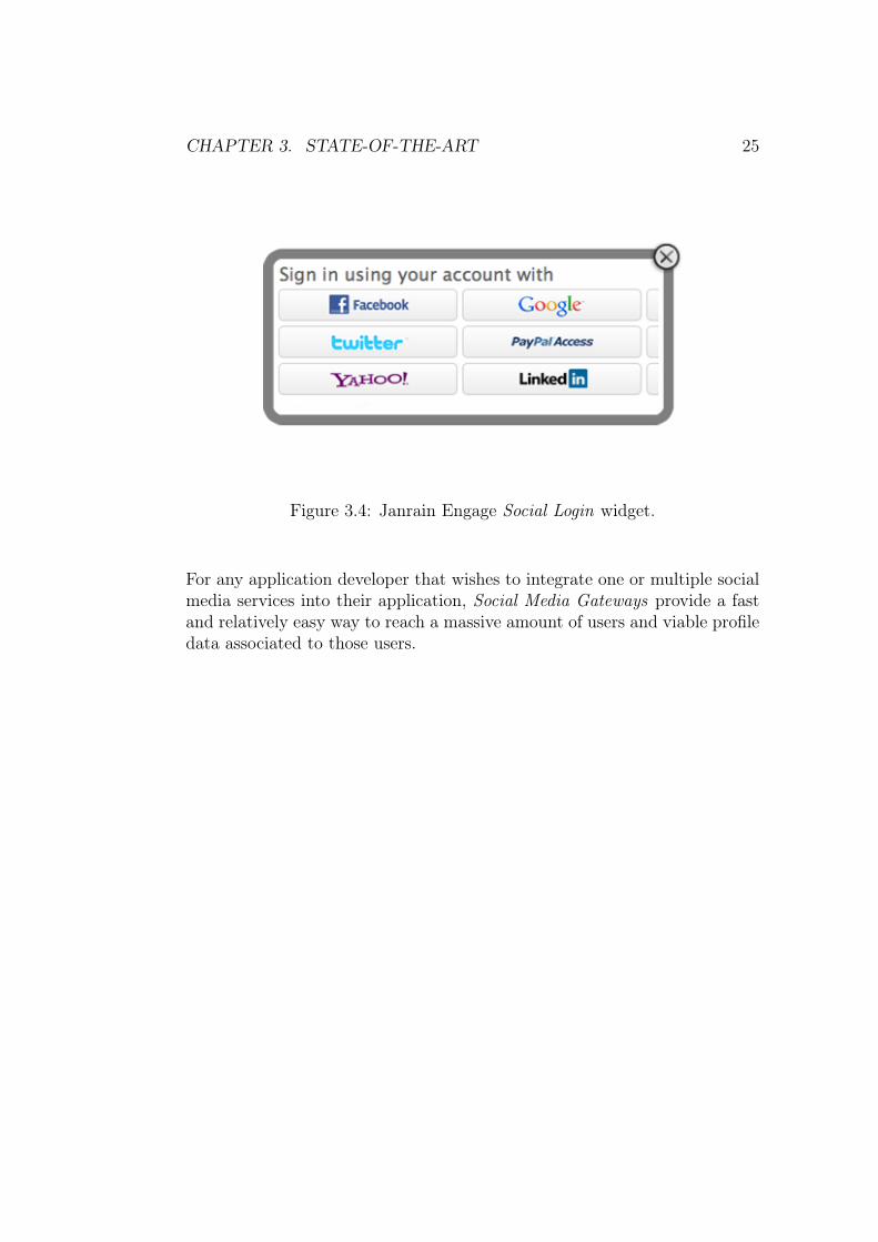
Gigya [54] and Janrain [55] are both services that act as a gateway betweenan application and a range of social media services. Both Gigya and Janrainprovide user management, JavaScript-based widgets (common social mediaactivities, such as login and sharing, through a UI) that can be embedded toa Web application, and an unified API-level access to social media services.Figure 3.4 shows a Social Login widget10 provided by Janrain.
8Facebook, http://www.facebook.com/9Twitter, https://twitter.com/
10Janrain Engage Social Login widget, http://janrain.com/wp-content/uploads/2012/03/Janrain-Engage-01.png
CHAPTER 3. STATE-OF-THE-ART 25
Figure 3.4: Janrain Engage Social Login widget.
For any application developer that wishes to integrate one or multiple socialmedia services into their application, Social Media Gateways provide a fastand relatively easy way to reach a massive amount of users and viable profiledata associated to those users.

Chapter 4
Research Aims
In this Chapter, the research settings of this Thesis are covered. First, theresearch objectives and scope are introduced. Then, the research problemsare presented and the research questions are formulated. Last, the methodsused for the research are demonstrated.
4.1 Research Objectives and Scope
The main research objective of this Thesis is two-fold. Firstly, the objective isto research the current solutions for controlling and creating Smart Spaces aswell as the possibilities of integrating existing devices and objects as part ofSmart Space controlling platforms. Secondly, the objective is to implementa proof-of-concept cloud-based platform for developing social Smart Spaceapplications. In addition, the usefulness and the performance of the platformis tested by developing two sample applications on top of it as well as bymeasuring the performance of the platform with a series of automated testruns.
Two kinds of premises have been used as a basis for Smart Spaces in this re-search, although the platform is designed for applications used in any kind ofSmart Space. The primary Smart Space context of this research is a shoppingcenter (Iso Omena1 shopping center for user tests) and the secondary SmartSpace is a living lab at Aalto Design Factory2. The requirements analysisfor the platform is based on the shopping center as a Smart Space and bothcontexts are used for the evaluation of the platform. The shopping center
1Iso Omena, http://www.isoomena.fi/2Aalto Design Factory, http://aaltodesignfactory.fi/
26
CHAPTER 4. RESEARCH AIMS 27
is considered as an environment complex enough to cover a wide variety ofSmart Space application scenarios, but the requirements may not be fullytransferable to all Smart Space contexts.
4.1.1 4D-Space Project
This Thesis has been made as part of the research conducted in the 4D-Space[56] project under theMultidisciplinary Institute of Digitalisation and Energy(MIDE) research program at the Aalto University. The aim of the 4D-Spaceproject is to research and implement novel retail services in collaborationwith both customers and retailers. Given the research goals of the project,the cloud-based platform developed within this Thesis focuses on providingfacilities for retail-centric services, although it is designed to scale outsidethe retail context.
4.2 Research Questions
As demonstrated in Chapter 3, there is a wide variety of platforms providingservices for integrating real-time communication, physical objects, position-ing, and social media as part of a Web application. However, most of theseplatforms offer features related to only one topic (e.g., platform independentserver push or social media integration) meaning that in order to utilize thefunctionality of several platforms, a developer needs an implementation foreach platform separately and is dependable on several third-party services.To study and overcome this problem, the main research question of the The-sis has been formulated as follows:
Q1: How to integrate server push, Smart Object integration, posi-tioning, and Social Login services under a single cloud-basedplatform?
In addition to the main research question, this Thesis aims to give an answerto other related questions as well. These secondary research questions are:
Q2: How to transform indoor environments to Smart Spaces byutilizing the existing plain and smart objects?
CHAPTER 4. RESEARCH AIMS 28
Q3: How to seamlessly integrate digital services as part of theeveryday physical activities?
The main research question of the Thesis aims to solve a more general prob-lem from the service and developer’s point of view, whereas the secondaryresearch questions focus more on the broad concepts (e.g., WoT and ubiqui-tous environments) of the Web 3.0 generation. In other words, the secondaryresearch questions focus on bridging the gap between the current and thenext generation of the Web by discovering ways to interconnect constrainedobjects with Web technologies and finding out ways for an environment toautonomously adjust as well as perform actions based on the changes andevents in that environment. By giving tools for the developers to create socialapplications that integrate digital and physical world with Web technologies,potentially any environment could be transformed into a Smart Space.
4.3 Research Methods
The research strategy for this Thesis consists of five steps. First, a state-of-the-art review of research, services, technologies, and best practices regardingto the concepts of the current and the next generation of the Web (i.e., Web2.0 and Web 3.0) is conducted. Second, a requirements analysis for theplatform is made by analyzing the results from the state-of-the-art reviewas well as the results [57, 58] gained from the previous research in the 4D-Space project. Third, a proof-of-concept prototype platform is designed andimplemented. Fourth, the usefulness of the platform is tested by creatingtwo sample applications, which are tested with real-world users. Last, theperformance of the platform is evaluated by running a series of automatedtest runs in the laboratory environment.

Chapter 5
Platform Requirements
In order to find all the requirements for the platform, the Smart Space context(the shopping center environment, cf. Chapter 4) was examined from threeaspects as follows:
• Terminals and devices,
• Users, and
• Objects.
Each aspect is covered in detail in the following sections. Then, the require-ments derived from analyzing the aspects are compared against the resultsobtained from empirical studies. Finally, the list of requirements for theplatform is conducted from the analysis.
5.1 Terminals and Devices
Nowadays, information should be accessible through a wide variety of devices.Users possess private terminals, such as smartphones, tablets, and laptops;and both indoor and outdoor environments are full of info kiosks, large in-formation displays, and shared computers. For the requirement analysis, thedisplays are divided into three categories:
29

CHAPTER 5. PLATFORM REQUIREMENTS 30
1. Public displays,
2. Semi-public displays, and
3. Private displays.
In order to support all the different display types (cf. above and Figure 5.1),the platform should be accessible from all kinds of devices and should provideinformation based on the context of use as well as based on the privacy levelof both the user (e.g., anonymous user or logged in user) and the display(e.g., smartphone or public information display).
Public screens e.g., info kiosks
Semi-public e.g., public PCs
Private e.g., mobile
Figure 5.1: Different display types.
5.2 Users
Google’s division of Mobile Users [59] was used as a basis for analyzingthe users. Although, Google’s analysis focuses on mobile phone users andnot users in general, it fits well on the Smart Space context with a variety ofdifferent terminals and dynamic user groups. According to Wellman, Google1
divides Mobile Users into three distinct categories that are:1Google, http://www.google.com/about/company/

CHAPTER 5. PLATFORM REQUIREMENTS 31
1. Repetitive Now,
2. Urgent Now, and
3. Bored Now.
The Repetitive Now user type wants repetitive information from well-definedsources regularly. For example, a user might check the latest news fromdedicated mobile applications from time to time. To satisfy the needs ofRepetitive Now users, the platform needs to provide access to informationwith pull-based methods (i.e., the data must be stored and be accessiblelater).
The Urgent Now user type wants relevant, personalized, and context-awareinformation in real-time. For example, a customer in a hurry inside a shop-ping center needs to know where is the nearest restaurant serving the foodshe likes, and where is the friend she is supposed to eat with. In order tofully serve the Urgent Now user type, the platform needs to be able to pushinformation in real-time, know the preferences as well as social connectionsof a user (i.e., the social media profiles), and be able to locate the user bothindoors and outdoors. Traditional positioning methods do not work or arenot accurate enough indoors, so in order to provide indoor location informa-tion, the service also needs to support the integration of different sensors totrack individuals and their movements.
The Bored Now user type does not need any specific information. This type ofa mobile user has some spare time and wants to be entertained. For example,a user waiting for a bus has a couple of minutes and wants to play a gamewith her mobile phone. In the context of this Thesis, the Bored Now usertype is considered the least important, because of the information-centricnature of Smart Spaces.
In addition to the users/visitors of any space, there are also other stake-holders, such as administrators of the space and employees (e.g., cleanersand janitors). For these type of users, it is important that the space canautonomously perform actions and signal conditions (e.g., open locks to re-stricted areas when a valid identity card is shown or calculate and show thenumber of free parking slots). To meet the needs of these users, the platformmust support the integration of various types of sensors in addition to thesensors related to indoor positioning.

CHAPTER 5. PLATFORM REQUIREMENTS 32
5.3 Objects
Different environments, especially shopping centers, are full of different ob-jects with pre-existing identifiers, such as Universal Product Codes (UPC) onproducts and International Standard Book Numbers (ISBN) on books. Toprovide a digital representation of these objects, the platform must recognizeobjects based on different codes.
5.4 Verification of the Requirements
To verify the requirements with real shopping center users, three workshopsin the Iso Omena shopping center were organized to collect ideas and opinionsabout the future of shopping centers [57, 58]. The workshops resulted to ap-proximately 450 ideas. The majority of the ideas reflected the requirementspresented above. For example, the participants of the workshops wanted togain more information on products (e.g., carbon footprint) with their mobilephones. They also felt that advertisements should be personal as well aslocation-aware and the information should be aggregated to a single shop-ping center UI. In addition, the customers hoped that there would be abi-directional channels between customers, retailers, and administrators toshare ideas and information. Furthermore, the participants also wished thatthey could share information to other services, which is a common practice inmodern Web applications. Based on the above, the platform should also sup-port aggregating information from various information sources and sharinginformation to social media.
5.5 Requirements
Based on the workshops, state-of-the-art review, and requirements analysis,a list of requirements (cf. Table 5.1) for the platform was conducted. Eachrequirement is covered more thoroughly in the following sub-sections.

CHAPTER 5. PLATFORM REQUIREMENTS 33
ID Name Description
R1 RESTful API
The platform must provide ac-cess to data in pull-based meth-ods as well as provide representa-tions and manipulation of physi-cal objects through a uniform in-terface.
R2 Server pushThe platform must be able topush data to clients in real-timeregardless of the client device.
R3 User profiles
The platform must be able toidentify users based on their ex-isting profiles and other identi-fiers as well as to provide infor-mation on users preferences andsocial connections.
R4 Positioning
The platform must be able toprovide and process location in-formation both outdoors and in-doors.
R5 Object recognition
The platform must be able toidentify objects based on dif-ferent identifiers, such as bar-codes or Near Field Communica-tion (NFC) enabled tags.
R6 Sensor integration
It must be possible to integratedifferent sensors to the platformin order to facilitate Smart Spacesand indoor positioning.
R7 Information aggregation
The platform must be able toaggregate information from con-nected applications, informationservices, and social media.
R8 Social sharingThe platform must provide meansfor sharing information to socialmedia.
Table 5.1: Requirements for the platform.

CHAPTER 5. PLATFORM REQUIREMENTS 34
5.5.1 R1: RESTful API
As stated earlier, some users (i.e., the Repetitive Now user type) wish toaccess specific type of information on-demand, at a time most suitable tothem. These users know what they want and when they want it. To servethese users, the platform should provide access to historical data through anAPI. In addition, the physical objects need to be represented and accessedin the digital context as well. To support these requirements, the platformshould provide an API-level access for the digital counterparts of physicalobjects.
5.5.2 R2: Server Push
In comparison to the Repetitive Now type users, the Urgent Now type userswant context-aware information to be pushed to them at all times. Theseusers want their preferred information to be pushed to them even if theyare not actively concentrated on the topic of information at that particularmoment. In order to satisfy these users, the platform needs to be able to pushinformation in real-time, regardless of the context, end device, or location.Furthermore, in the Smart Space context, some actions are autonomouslyperformed based on events triggered by Smart Objects. In order to functionseamlessly, the events have to be transmitted in real-time.
5.5.3 R3: User Profiles
To fulfill the requirements R1 and R2, the information provided should varyper user basis. In order to provide personalized information, the platformmust provide user information (i.e., user profiles and social connections). Inaddition, it is crucial for Smart Space environments to be able to separatea user from another in order to adjust the space and perform actions basedon a particular user. To accomplish the above requirements, the platformmust provide the ability to integrate existing social media as well as customprofiles to users (e.g., an NFC identity for performing actions within a SmartSpace).

CHAPTER 5. PLATFORM REQUIREMENTS 35
5.5.4 R4: Positioning
For Smart Spaces and location-based applications, it is vital to be able tolocate objects and people accurately. Positioning in a shopping center envi-ronment is especially important because it is full of both indoor and outdoorareas providing different kinds of services, some more relevant than others,to a particular person. From a customer’s point of view, it is importantthat both the customer and the services she is interested in are accuratelypositioned. From an administrator’s point of view, it is important to be ableto track movements inside a space in order to spot which areas are morecrowded than others and to utilize that data in further planning. To satisfythese requirements, the platform must provide accurate location informationof individual users both indoors and outdoors as well as the flow of peopleinside the space.
5.5.5 R5: Object Recognition
In a Smart Space environment, objects must contain some kind of an identifierso that these objects can be mapped to a correct digital representation. Theimportance of identifying an object varies based on the characteristics ofit. Even with a plain object not capable of performing any autonomousactions, it is valuable to have a digital representation. The representationcan be used to store information that cannot be embedded to the physicalrepresentation, such as the carbon footprint of a product or the amount ofloans for a particular library book. In order to identify also plain objects,the platform must be able to recognize objects based on different codes.
5.5.6 R6: Sensor Integration
As discussed earlier, positioning in indoor environments is not an easy tasksince the most used positioning techniques (e.g., GPS) do not work indoorsor do not provide accurate enough information. In order to provide usablelocation information in Smart Spaces, a room level accuracy should be con-sidered to be the minimum requirement. To be able to provide such anaccurate indoor location information, different kinds of sensing devices areneeded in different spaces.
In addition to indoor positioning, sensors can provide valuable informationfor Smart Space administrators. For example, anonymous people flow track-ing provides information about the most popular or crowded areas of the

CHAPTER 5. PLATFORM REQUIREMENTS 36
space, sensors can keep track of the available rooms or parking slots in thearea, or an electricity consumption as well as the state of individual elec-tronic appliances can be easily monitored and controlled. To satisfy all kindsof sensor-based activities, the platform must support the integration of dif-ferent kinds of sensors.
5.5.7 R7: Information Aggregation
In a Smart Space, there is usually many information sources providing dif-ferent information valuable for the users in that space. For example, in ashopping center a particular visitor might want to know where her friend is(personal information), a shop could advertise clothing for women (informa-tion targeted to a group), and a shopping center might want to inform allcustomers that the center is going to be closed in fifteen minutes (commoninformation). The more information sources there are, the harder it is for theusers to gain access to all the important information. To be able to deliver allthe relevant information, the platform must be able to aggregate informationfrom various information sources.
5.5.8 R8: Social Sharing
The Web 2.0 era and the emergence of social media have made it possiblefor users to become content providers on the Web. The users have becomeaccustomed to be able to share information from almost any kind of Webapplication to social networks. To be able to facilitate these actions, theplatform must provide means for sharing information to social networks,such as Facebook.
Chapter 6
Implementation
In this Chapter, a proof-of-concept implementation, the UbiQloud platform,is described. First, a brief overview of the platform is presented. Next, theserver-side architecture of the platform is introduced. Then, the internalarchitecture of the UbiQloud application is described in detail, and last, thecommunication methods and protocols used to interact with the platform arecovered.
6.1 UbiQloud Overview
UbiQloud is a cloud-based PaaS facilitating rapid development of social,location- and context-aware, real-time applications for smart indoor spaces.The platform provides a Web-based UI for developers, in which they canregister applications and gain necessary resources to interact with UbiQloud.Figure 6.1 represents the overall communication architecture of UbiQloud.The platform can be divided into three kinds of interfaces that are (1) clientAPIs, (2) a Smart Gateway, and (3) a Social Gateway. Clients (i.e., the appli-cations developed on top of UbiQloud) can communicate with the pull-basedAPIs using HTTP protocol and with the push-based APIs using XMPP (mo-bile applications) or XMPP over WebSocket (Web applications). The SmartGateway is responsible for communicating with integrated sensors. TheUbiQloud/sensor communication is established over HTTP or TCP Socket.The Social Gateway consist of a set of APIs and a widget that can be usedto integrate multi-service Social Login to client applications.
37

CHAPTER 6. IMPLEMENTATION 38
SocialGateway
ClientAPIs
Sensors
TCPHTTP
QMobile
Web
XMPP over WebSocketHTTP
HTTPXMPP
SmartGateway
HTTP
Figure 6.1: UbiQloud communication architecture.
From a service point of view, UbiQloud provides mechanisms for developersto:
• Integrate sensors,
• Manage users,
• Access user data on social media services,
• Use and extend a shared database of objects, and
• Store and access data with both pull- and push-based methods.
UbiQloud does not restrict the type of sensor to be integrated. However, forparsing and manipulating the sensor data on the cloud before pushing it for-ward, a dedicated driver should be implemented. At the moment, UbiQloudonly contains drivers for two types of sensors that are (1) a custom WirelessSensor Network (WSN), RealSense, for monitoring people flow and (2) FeigLRU Ultra-High Frequency (UHF) reader. The data coming from sensorslacking a driver is pushed as is. Each sensor has its own dedicated channelwhere to the data is pushed in real-time. Sensors can communicate withUbiQloud either through an HTTP interface or a raw TCP socket.
Each UbiQloud user contains an ID and XMPP credentials, which are sharedwith all UbiQloud applications. In addition, a user object can possess any

CHAPTER 6. IMPLEMENTATION 39
number of application-specific profiles (e.g., a Facebook or NFC profile).The profiles are application specific in order to protect users’ privacy (i.e.,a user must authorize an application to use a particular profile). For theauthorization of social media profiles, UbiQloud provides a JavaScript widgetthat can be embedded to an application.
Similar to the users, UbiQloud also hosts a database for objects. Each objecthas public properties, such as an identifier (e.g., UPC or ISBN), a set of tagsfor textual representation of the object, and a set of images. In addition to thepublic properties, each object has a set of application-specific activities (e.g.,likes, comments, and ratings) to be used in an application-specific context.Furthermore, each activity is related to one application and one user.
Both users and objects in UbiQloud have also application-specific locationfeeds. An application can send coordinates (a latitude/longitude pair) toUbiQloud, which in turn converts the coordinates to a textual representation.
Data in UbiQloud is accessible with both pull- and push-based methods. Inmost cases, the data is processed in similar way. First, UbiQloud receives arequest (e.g., a sensor sends new data or a user comments an object throughan application UI) that affects on the data. Second, the data is stored in adatabase for later access through pull-based APIs, and third, the new datais pushed to connected clients through a dedicated channel. In other words,UbiQloud supports a common scenario, in which the history data is fetched(pull) from the server at application startup, and as long as the applicationis running, the data is kept up-to-date in real-time (push).
The platform aims to fulfill developers’ needs in a variety of integration levels.UbiQloud can be used as the sole back-end solution for an application or asingle module can be integrated to a custom solution. The main target groupfor UbiQloud is freelance developers or small businesses in need for a platformto rely on modern, Web 3.0 applications.
6.2 Server Components
UbiQloud relies only on free, widely used, and easily configurable third-partycomponents. The idea is that setting up UbiQloud instances would be aseasy as possible regardless of the environment (e.g., Windows, OS X, orLinux). Figure 6.2 represents the server-side architecture of the platform.The architecture consists of three third-party components that are:
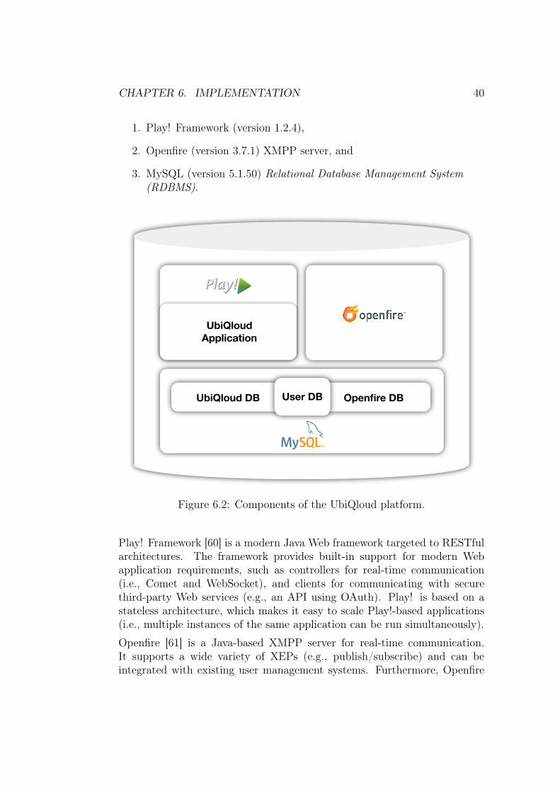
CHAPTER 6. IMPLEMENTATION 40
1. Play! Framework (version 1.2.4),
2. Openfire (version 3.7.1) XMPP server, and
3. MySQL (version 5.1.50) Relational Database Management System(RDBMS).
UbiQloudApplication
UbiQloud DB Openfire DBUser DB
Figure 6.2: Components of the UbiQloud platform.
Play! Framework [60] is a modern Java Web framework targeted to RESTfularchitectures. The framework provides built-in support for modern Webapplication requirements, such as controllers for real-time communication(i.e., Comet and WebSocket), and clients for communicating with securethird-party Web services (e.g., an API using OAuth). Play! is based on astateless architecture, which makes it easy to scale Play!-based applications(i.e., multiple instances of the same application can be run simultaneously).
Openfire [61] is a Java-based XMPP server for real-time communication.It supports a wide variety of XEPs (e.g., publish/subscribe) and can beintegrated with existing user management systems. Furthermore, Openfire
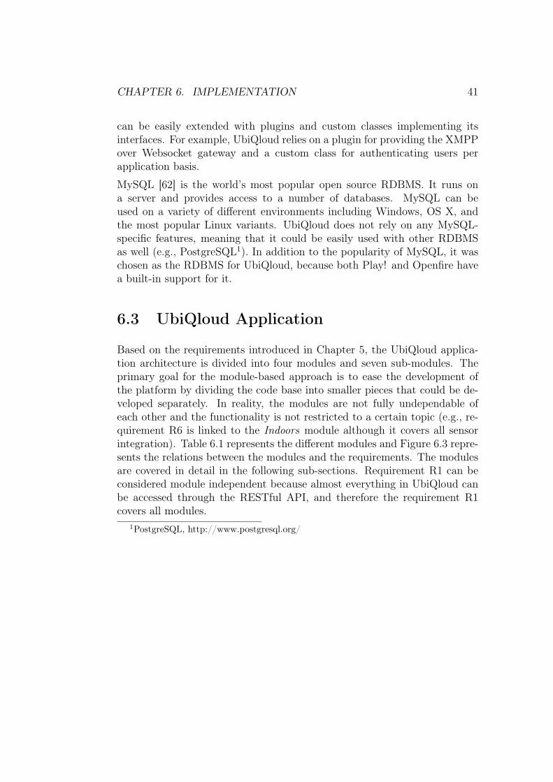
CHAPTER 6. IMPLEMENTATION 41
can be easily extended with plugins and custom classes implementing itsinterfaces. For example, UbiQloud relies on a plugin for providing the XMPPover Websocket gateway and a custom class for authenticating users perapplication basis.
MySQL [62] is the world’s most popular open source RDBMS. It runs ona server and provides access to a number of databases. MySQL can beused on a variety of different environments including Windows, OS X, andthe most popular Linux variants. UbiQloud does not rely on any MySQL-specific features, meaning that it could be easily used with other RDBMSas well (e.g., PostgreSQL1). In addition to the popularity of MySQL, it waschosen as the RDBMS for UbiQloud, because both Play! and Openfire havea built-in support for it.
6.3 UbiQloud Application
Based on the requirements introduced in Chapter 5, the UbiQloud applica-tion architecture is divided into four modules and seven sub-modules. Theprimary goal for the module-based approach is to ease the development ofthe platform by dividing the code base into smaller pieces that could be de-veloped separately. In reality, the modules are not fully undependable ofeach other and the functionality is not restricted to a certain topic (e.g., re-quirement R6 is linked to the Indoors module although it covers all sensorintegration). Table 6.1 represents the different modules and Figure 6.3 repre-sents the relations between the modules and the requirements. The modulesare covered in detail in the following sub-sections. Requirement R1 can beconsidered module independent because almost everything in UbiQloud canbe accessed through the RESTful API, and therefore the requirement R1covers all modules.
1PostgreSQL, http://www.postgresql.org/

CHAPTER 6. IMPLEMENTATION 42
ID NameM1 Recognizem1.1 User Profilesm1.2 ObjectsM2 Locatem2.1 Indoorsm2.2 OutdoorsM3 Connectm3.1 Pushm3.2 AggregateM4 Sharem4.1 Social Media
Table 6.1: UbiQloud modules.
6.3.1 Recognize Module
In order to fulfill the requirements R3 and R5, the Recognize (M1) modulewas implemented. The module consists of two sub-modules that are UserProfiles (m1.1) and Objects (m1.2). Every UbiQloud user (i.e., any user ofany application developed on top of UbiQloud) is represented as an objectwith various profiles and a location feed. All the users have an unique XMPPprofile, which is automatically created during the first login and is completelytransparent to the user. In addition, users have a set of application-specificprofiles ranging from different social media profiles to digital identifiers, suchas NFC tags and Bluetooth devices.
Objects in UbiQloud behave similar to users. They are also identified andthey have a location feed. However, objects do not have profiles like users buta single unique identifier. In addition, all objects have application-specificactivity feeds consisting of different activities made by users. A single activitycan be, for example, a like, a comment, or a check-in. UbiQloud allowsusing any of the provided activities with any kind of object.

CHAPTER 6. IMPLEMENTATION 43
Push
Outdoors
RecognizeUser Profiles
Objects
LocateIndoors
ConnectAggregate
Share Social Media
R3, R5
R4, R6
R2, R7
R8
R1
Figure 6.3: Relations between the UbiQloud modules and requirements.
6.3.2 Locate Module
The Locate (M2) module represents the requirements R4 and R6 and consistsof the Indoors (m2.1) and Outdoors (m2.2) sub-modules. As the sub-moduletopics suggest, the aim of the modules is to provide positioning related func-tionality. Although positioning is the core context, the Indoors sub-moduleis responsible for all sensor integration with the UbiQloud platform (i.e., thesensor interfaces and drivers). The Indoors sub-module can be used withany sensor, but in order to gain parsed and well-formed data, a dedicateddriver for each sensor should be implemented. At the moment, the driversimplemented (RealSense and Feig LRU) are meant for indoor positioning.
The Outdoors sub-module is responsible for providing meaningful outdoorlocation data for other modules and applications. The main task of thesub-module is to receive coordinate points and transform those coordinatesto textual representation by utilizing the MapQuest Nominatim Search APIWeb Service2.
2MapQuest Nominatim Search API Web Service,http://developer.mapquest.com/web/products/open/nominatim

CHAPTER 6. IMPLEMENTATION 44
6.3.3 Connect Module
For the requirements R2 and R7 the Connect (M3) module was implemented.The module consists of two communication related sub-modules, that arePush (m3.1) and Aggregate (m3.2). The Push sub-module is responsiblefor all the real-time communication functionality in UbiQloud. When a datamanipulation request is received by UbiQloud, the Push sub-module performsthree steps as follows:
1. Intersects the request,
2. Converts the data to XML if possible/needed (the data is alreadyparsed, manipulated, converted, and stored by other modules), and
3. Pushes the data to a dedicated channel (e.g., sensor feed or applicationfeed).
Figure 6.4: Example of using the UbiQloud APIs for pushing the locationinformation of a user.
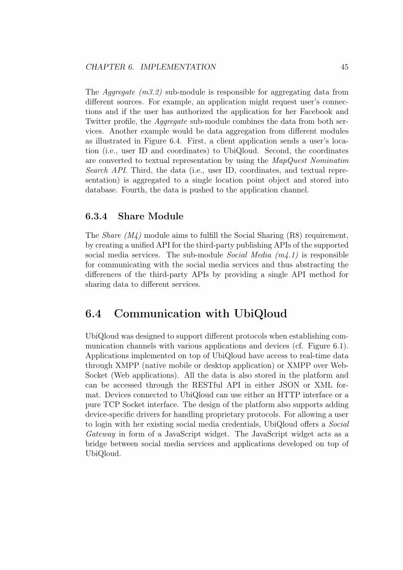
CHAPTER 6. IMPLEMENTATION 45
The Aggregate (m3.2) sub-module is responsible for aggregating data fromdifferent sources. For example, an application might request user’s connec-tions and if the user has authorized the application for her Facebook andTwitter profile, the Aggregate sub-module combines the data from both ser-vices. Another example would be data aggregation from different modulesas illustrated in Figure 6.4. First, a client application sends a user’s loca-tion (i.e., user ID and coordinates) to UbiQloud. Second, the coordinatesare converted to textual representation by using the MapQuest NominatimSearch API. Third, the data (i.e., user ID, coordinates, and textual repre-sentation) is aggregated to a single location point object and stored intodatabase. Fourth, the data is pushed to the application channel.
6.3.4 Share Module
The Share (M4) module aims to fulfill the Social Sharing (R8) requirement,by creating a unified API for the third-party publishing APIs of the supportedsocial media services. The sub-module Social Media (m4.1) is responsiblefor communicating with the social media services and thus abstracting thedifferences of the third-party APIs by providing a single API method forsharing data to different services.
6.4 Communication with UbiQloud
UbiQloud was designed to support different protocols when establishing com-munication channels with various applications and devices (cf. Figure 6.1).Applications implemented on top of UbiQloud have access to real-time datathrough XMPP (native mobile or desktop application) or XMPP over Web-Socket (Web applications). All the data is also stored in the platform andcan be accessed through the RESTful API in either JSON or XML for-mat. Devices connected to UbiQloud can use either an HTTP interface or apure TCP Socket interface. The design of the platform also supports addingdevice-specific drivers for handling proprietary protocols. For allowing a userto login with her existing social media credentials, UbiQloud offers a SocialGateway in form of a JavaScript widget. The JavaScript widget acts as abridge between social media services and applications developed on top ofUbiQloud.

CHAPTER 6. IMPLEMENTATION 46
6.4.1 RESTful API
For accessing the data stored in UbiQloud retrospectively, the platform pro-vides an HTTP-based RESTful API. The REST-based architecture is wellsuited for UbiQloud because UbiQloud contains resources, which are linked tophysical objects (i.e., smart objects). The API is divided into four parts rep-resenting users, objects, sensors, and applications. The resources are accessedwith HTTP methods (GET, POST, PUT, and DELETE ) and identified withthe following URL patterns:
URLhttp://api.ubiqloud.io/{user|object|sensor|app}/...
For example the following request:
HTTP GEThttp://api.ubiqloud.io/object/1/activity/1
could result the following response in JSON:{"activity" :
{"id" : 1,"type" : "like","published" : "2011 -02 -07 11:18:32.0","userid" : "foobar"}
}
Listing 6.1: Example of the JSON representation of a resource
or in XML:<activity >
<id>1</id><type>like</type><published >2011 -02 -07 11 :18:32 .0</published ><userid >foobar </userid >
</activity >
Listing 6.2: Example of the XML representation of a resource
To make sure that the data is accessible only for authorized parties, severalmethods have been implemented to secure the API and to identify the clientapplication making a request (cf. Figure 6.5). The API security proceduresare inspired by the Signature version 2 [63] of the Amazon Web Services(AWS).

CHAPTER 6. IMPLEMENTATION 47
1. Generate a base URLe.g., http://api.ubiqloud.io/object/1/activity/1
2. Append appid and timestamp parametershttp://api.ubiqloud.io/object/1/activity/1
?appid=d41d8cd98f00b204e9800998ecf8427e×tamp=1338193970480
3. Generate a hash from the URL with application secret
975f60d234e66b8c9ed8c0f6957bf46f4be95800939878941bc4fdf9c4183d2b
5. API request
6. Compare the timestamp parameter against the current UTC
Request expired
7. Fetch the application secret based on the appid parameter
Not found
8. Exclude the signature parameter and regenerate the hash
4. Append the hash as a signature parameterhttp://api.ubiqloud.io/object/1/activity/1
?appid=d41d8cd98f00b204e9800998ecf8427e×tamp=1338193970480
&signature=975f60d234e66b8c9ed8c0f6957bf46f4be95800939878941bc4fdf9c4183d2b
9. Compare the hash against the signatureInvalid signature
10. Process the request11. API response
Client Application UbiQloud
Figure 6.5: Secure communication with the UbiQloud RESTful API.
Once a developer registers an application to UbiQloud, unique ID and se-cret — that is public and private keys — are generated for the application.For every request the application makes against the API, three additionalparameters should be included into the URL. The first parameter is appidwith the value of the ID assigned to the application. The second parame-ter is timestamp with the value of the current Coordinated Universal Time(UTC) time in milliseconds. The third parameter is signature with a base64encoded Hash-based Message Authentication Code (HMAC) generated fromthe request string and the application secret with the SHA-256 cryptographichash function. For example, the request presented above could look as fol-lows:

CHAPTER 6. IMPLEMENTATION 48
HTTP GEThttp://api.ubiqloud.io/object/1/activity/1?appid=d41d8cd98f00b204e9800998ecf8427e×tamp=1338193970480&signature=975f60d234e66b8c9ed8c0f6957bf46f4be95800939878941bc4fdf9c4183d2b
When UbiQloud receives the request, it first compares the timestamp pa-rameter against the current UTC time and if the value of the timestamp ismore than five minutes in the past the request is rejected. The timestampcomparison is made to prevent replay attacks (a hostile party copies a re-quest and tries to use the same request in the future to make authenticatedAPI calls). If the timestamp is valid, the appid parameter is used to fetchthe correct application secret from the database. Then, the signature pa-rameter is omitted from the request string and the same hashing operationmade in the application side is made in UbiQloud as well. If the resultedhash value equals to the value of the signature parameter, UbiQloud canbe sure that the request has come from the application and the request isdelegated to the controller processing the actual operation requested.
6.4.2 Server Push Interfaces
Server push in UbiQloud is based on the publish/subscribe architecture anduses XMPP and related XEPs (namely, XEP-0060: Publish-Subscribe) asthe underlying protocols for real-time communication. In UbiQloud, thepublisher is always the platform itself, meaning that all the push eventsare emitted from operations in the RESTful API. There is two reasons fornot allowing a client application to use real-time channels directly. First ofall, the data needs to be stored and possibly manipulated for later use in acorrect format (i.e., XML or JSON). Second of all, by restricting the wayto publish data, an application cannot accidentally or deliberately pollutewrong channels.
The publish/subscribe model fits well for the service-oriented nature ofUbiQloud. The platform consists of related, yet loosely-coupled, servicesthat need to provide data both to each other and to a dynamic group of dataconsumers (i.e., applications developed on top of the platform and Smart Ob-jects integrated to it). In other words, the platform includes services, users,objects, sensors, and applications that do not need to be aware of each other,but need to be able to provide data to each other. To facilitate this kind of aloosely-coupled system, each entity capable of creating or manipulating datahas a unique channel to push changes. For example, a sensor communicating

CHAPTER 6. IMPLEMENTATION 49
with UbiQloud could provide valuable data to several applications, but itdoes not need to know the identity of these applications (the amount andtype of consumer applications may vary over time). Furthermore, some ofthe applications might need data from other sensors as well, but the sensorsdo not need to be aware of each other (i.e., a centralized data broker for allthe sensors would not be an optimal solution). The solution is to provide aunique channel (node) for every sensor to push data and let interested partiesto subscribe to that channel.
XMPP was chosen as the real-time communication protocol for several rea-sons. Firstly, It is a mature, well supported, and standardized protocol.Numerous client libraries exists for several platforms and languages, mean-ing that XMPP would not become a bottleneck for developing UbiQloudapplications. Secondly, XMPP is extensible and there is already a vast rangeof extensions covering features needed in UbiQloud (e.g., publish/subscribe).Furthermore, because of the extensibility, it is possible to implement custom,platform-specific extensions if needed. Thirdly, XMPP has a built-in supportfor user management, authentication, and presence, which is important forthe UbiQloud platform (i.e., regardless of the social media profiles, users needto be able to authenticate to the platform in a common way). Lastly, XMPPis reliable and secure [12], which is important for UbiQloud, because (1) itconsist of interconnected entities that rely on each other, and (2) it mediatessensitive and private data (e.g., user and application-specific data).
As stated in Chapter 2 (Section 2.1.2), although XMPP is a widely used pro-tocol for real-time communication, it is hardly used in traditional Web appli-cations, because none of the major Web browsers support it natively. Luckily,XMPP can also be used [16, 21] over protocols suitable for Web browser en-vironments. To support also browser-based applications, UbiQloud providesa WebSocket gateway for XMPP communication.
Every user in UbiQloud has a shared XMPP profile (i.e., unlike social mediaprofiles, the XMPP profile is not application specific). Even if the XMPPprofile of a user is available to all UbiQloud applications, UbiQloud requiresthat an application making the connection (e.g., user authentication) on be-half of a user is a registered application. In general, when a user wishesto authenticate to an XMPP server, the identity (i.e., Jabber ID, JID) andpassword of the user is sent to server. In UbiQloud, the JID is sent as is,but instead of the password the application must send a string in format{appid}:{hash}, where hash is a base64 encoded HMAC constructed fromthe user’s XMPP password and application’s secret with the SHA-256 cryp-tographic hash function.

CHAPTER 6. IMPLEMENTATION 50
Once authenticated, the user is able to subscribe to any number of channels tostart receiving real-time updates through the push interfaces. For example, ifsubscribed to the application’s channel in which another user adds an activityto an object, the following XMPP message could be received:<message from="pubsub.ubiqloud.io" to="[email protected]
" id="foo"><event xmlns="http:// jabber.org/protocol/pubsub#event">
<items node="{unique node identifier}"><item id="ae890ac52d0df67ed7cfdf51b644e901">
<root><object id="1">
<activity id="1" method="post"><type>like</type><published >2011 -02 -07 11 :18:32 .0</published ><userid >foobar </userid >
</activity ></object >
</root></item>
</items ></event >
</message >
Listing 6.3: Example of an XMPP publish/subscribe message.
6.4.3 Smart Gateway
When a developer integrates a sensor to UbiQloud, the type and InternetProtocol (IP) address of the sensor must be specified. The type can be oneof the known sensor types (i.e., RealSense or Feig LRU) or undefined. In thecase of the known sensor types, the received data is manipulated to moreusable form (i.e., XML) before storing and pushing forward. In the case ofan undefined type, the data is stored and pushed as is. The IP address isused to identify the sending server when new data is received in UbiQloud.If the IP address is known, the data can be treated correctly (i.e., where tostore and push), and if the address is unknown the data is ignored. Eachsensor has a unique channel, where the data is pushed when ready.
For communicating with UbiQloud, there are two kinds of interfaces avail-able for sensors. One is a HTTP interface and the other is a TCP Socketinterface. For using the HTTP interface, a sensor must send either a GETor POST request to a dedicated URL (http://api.ubiqloud.io/sensor)with the data as a value of the data parameter. The other option, the TCPSocket interface, can be used by initializing a socket connection to UbiQloud

CHAPTER 6. IMPLEMENTATION 51
(ubiqloud.io) through the port 9999. Once the connection is established,new data can be sent anytime.
6.4.4 Social Gateway
In general, to integrate a Social Login provided by any social media service, adeveloper needs to complete certain steps. First, an application needs to becreated in the platform. During the application creation, a developer needsto provide some basic information (e.g., name of the application and URLused to communicate with the API) and gain application specific keys tosecurely communicate with the social media service. Second, a JavaScriptwidget needs to be embedded to the client application and initialized withapplication-specific options (e.g., public key). Third, a controller that com-municates with the social media services during and after the authorizationprocess needs to be implemented. From a developer’s point of view, the prob-lem is that social media services use different techniques for the authorization(e.g., different versions of OAuth or OpenID/OAuth hybrids) and differentlyimplemented APIs. In other words, to support more than one Social Loginproviders, a developer needs a unique implementation for each service.
To ease the Social Login integration, UbiQloud provides a unified mechanismto integrate multiple Social Login providers. The mechanism works similarlyas described above. First of all, a developer still needs to register applicationsto the social media services individually, because the users need to give anauthorization per application basis. Once the applications are created, thedeveloper adds the key pairs to UbiQloud which allows UbiQloud to commu-nicate with the social media service on behalf of the client application. Afterthe keys are added to UbiQloud, the developer can start using the SocialLogin service as illustrated in Figure 6.6.
First, the developer embeds the Social Login widget provided by UbiQloud tothe client application as well as initializes it with an application specific URLand the target URL to post a one-time token (cf. Listing 6.4). The widgetprovides an UI to login to all the supported services (i.e., Facebook, Twitter,and LinkedIn). Once the user is logged in to a selected social media serviceand has authorized the application, UbiQloud receives the user informationand user-specific tokens.

CHAPTER 6. IMPLEMENTATION 52
Figure 6.6: Six steps for Social Login through UbiQloud.
Then, a one-time token is generated in UbiQloud and sent to the client ap-plication via the widget. After receiving the token, the client application canexchange it to the user profile information. The authorization part needsto be completed only once per application and once authorized, the applica-tion can interact with the social media service on behalf of the user throughUbiQloud’s unified RESTful APIs.<input id="UQ_login_button" type="button" value="{login
button label}"/><script type="text/javascript" src="http :// ubiqloud.io/public
/javascripts/widgets.js"></script ><script type="text/javascript">
UQ.init("{appid}. ubiqloud.io", "{token URL}");</script >
Listing 6.4: Example of embedding the UbiQloud Social Login widget.

Chapter 7
Sample Applications
This chapter demonstrates two sample applications, FeedThroat and InView,developed on top of the UbiQloud platform. The sample applications weredeveloped for testing two aspects of the platform as follows:
1. Does the implemented platform meet the requirements set, and
2. Does the implemented platform work with real applications in real-world settings.
The first sample application, FeedThroat, was developed in conjunction withthe first version of the UbiQloud core (i.e., FeedThroat was not initially aseparate application, but part of the UbiQloud code base). The reason forthe tight integration was to be able to easily test different technologies andtweak the APIs. The second sample application, InView, was developed as aseparate application to actually test UbiQloud as a PaaS. A detailed overviewof the sample applications is given in the following sections.
7.1 Retail Context: FeedThroat
FeedThroat is a social shopping assistant application developed for iOS1 andthe Web. The core idea of the application is to provide retailer indepen-dent product information with social sharing and collaboration functional-ity. The iOS version of the application is targeted for regular users (i.e.,
1iOS is the operating system used in iPhone, iPod Touch, and iPad
53

CHAPTER 7. SAMPLE APPLICATIONS 54
customers) and it contains all end-user specific functionalities. The Web ver-sion of the FeedThroat also contains most of the features (excluding camera-related functionality) for end-users. However, the main target group of theWeb version is retailers, and therefore it contains retailer features not presentin the iOS application.
(a) Scanning a product (b) Viewing product information (c) Adding a product to a list
Figure 7.1: FeedThroat UI views in iOS application.
Figure 7.1 represents the main functionalities of the iOS application. First,the user can use the smartphone’s built-in camera to scan the barcode of aproduct (a) to gain instant information of it (b). In addition to the traditionalproduct information, there is a social layer on top of it including photos,comments, and a list of friends interested in the same product. Second,the application allows users to generate shared shopping lists with real-timeupdates and in-list product information (e.g., private comments and photos).Users are able to drop products to a list (c) by scanning a barcode, manuallyentering a product, or choosing from a dynamic product list of the newestproducts. Products in shared lists can also be checked as purchased (i.e.,similar to tasks in todo lists that can be marked as done). The ability tocheck products is useful for example in shared shopping lists.
As mentioned, the Web version of FeedThroat shares most of the function-ality with the iOS version. In addition, the Web application also provides acustom view for retailers, in which they can add products, events, and ads
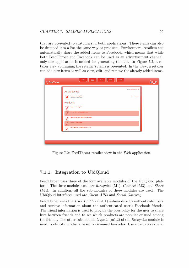
CHAPTER 7. SAMPLE APPLICATIONS 55
that are presented to customers in both applications. These items can alsobe dropped into a list the same way as products. Furthermore, retailers canautomatically share the added items to Facebook, which means that whileboth FeedThroat and Facebook can be used as an advertisement channel,only one application is needed for generating the ads. In Figure 7.2, a re-tailer view containing the retailer’s items is presented. In the view, a retailercan add new items as well as view, edit, and remove the already added items.
Figure 7.2: FeedThroat retailer view in the Web application.
7.1.1 Integration to UbiQloud
FeedThroat uses three of the four available modules of the UbiQloud plat-form. The three modules used are Recognize (M1), Connect (M3), and Share(M4). In addition, all the sub-modules of these modules are used. TheUbiQloud interfaces used are Client APIs and Social Gateway.
FeedThroat uses the User Profiles (m1.1) sub-module to authenticate usersand retrieve information about the authenticated user’s Facebook friends.The friend information is used to provide the possibility for the user to sharelists between friends and to see which products are popular or used amongthe friends. The other sub-module Objects (m1.2) of the Recognize module isused to identify products based on scanned barcodes. Users can also expand

CHAPTER 7. SAMPLE APPLICATIONS 56
the UbiQloud Object database through FeedThroat UI by providing a textualrepresentation for the unrecognized object.
All the data changes made in FeedThroat are pushed to other FeedThroatinstances through the Push (m3.1) sub-module. The iOS version uses nativeXMPP for real-time communication and the Web version uses XMPP overWebSocket. FeedThroat also uses the UbiQloud RESTful API to fetch dataduring the application initialization process and during other operations,such as fetching friend information.
The Share (M4) module is used by the retailer users of FeedThroat to dissem-inate information to social media. For example, ads created in FeedThroatcan be automatically shared to Facebook.
7.1.2 User Tests
For testing the application with real users, a small user test [57] was orga-nized with 15 participants (divided to two groups) in the Iso Omena shoppingcenter. The participants were given a task to buy a set of products to orga-nize a party. For the task, the participants were divided to pairs and eachpair gained a smartphone with a pre-installed FeedThroat application. Inaddition, the list of needed products was populated to FeedThroat beforethe test. The list contained products from various shops in order to preventone group for purchasing everything from a single shop.
The idea was that the pairs did not decide beforehand which pair is going tobuy what. Instead, the pairs used FeedThroat to scan and check products asthey purchased them. As soon as a product was checked by one pair, all theother pairs gained a notification that the particular product was purchased.
The test showed that communication (both pull and push) with UbiQloudworked well even in a crowded shopping center over a 3G cellular network.The latency of the communication was not measured, but at least the usersdid not complain about slowness in data fetching (e.g., scanned barcode wassent to UbiQloud and product information was received fast). Also, all pushnotifications were sent correctly without any dropped messages.

CHAPTER 7. SAMPLE APPLICATIONS 57
7.2 Positioning Context: InView
InView is a cross-platform mobile application for monitoring people flow in-doors. The application was developed with Web technologies — that is,HTML, Cascading Style Sheets (CSS), and JavaScript — and cross-compiledto multiple mobile Operating Systems (OS) with PhoneGap2. The main pur-pose of the InView application is to visualize both authenticated and anony-mous movements in indoor spaces. The location data was obtained from twotypes of sensors integrated to UbiQloud. A set of UHF readers were used toidentify individual users and their location based on user-specific RFID tags.For anonymous people flow (i.e., the amount and direction of people passingby), a custom ZigBee-based WSN was used.
Figure 7.3 illustrates the three main views of the application. The firstview is a location feed sidebar (a) that is updated in real-time based onthe movements of identified users. The second view, called Live View (b),visualizes the people flow by drawing a hit map on top of a floor map. Thefinal view, called History View (c), can be used to retrospectively view theamount of people passed by each sensor on both directions at a given timepoint. The History View contains two sliders to adjust the date and the timewithin one hour interval.
(a) Sidebar and (b) Live View in iPad (c) History View in HTC Desire
Figure 7.3: InView UI views in Android and iOS devices.
2PhoneGap, http://phonegap.com/

CHAPTER 7. SAMPLE APPLICATIONS 58
7.2.1 Integration to UbiQloud
InView utilizes the first three main modules (M1, M2, and M3) of UbiQloud.From the main modules, the most relevant sub-modules for the applicationare Indoors (m2.1), User Profiles (m1.1), Push (m3.1), and Aggregate (m3.2).In addition, all UbiQloud interfaces are used (i.e., Client APIs, Smart Gate-way, and Social Gateway).
The indoor space, Aalto Design Factory monitored with InView, has twotypes of sensors integrated to UbiQloud. For people flow monitoring, thereis a ZigBee-based WSN that monitors movements and sends each pulse toUbiQloud, which in turns pushes the data to a dedicated channel subscribedby InView. As the data arrives to InView, a small animation illustratingactivity and the direction of the movement is presented in the Live View atthe spot of the sensor.
For identifiable movements, there is a set of UHF readers installed in thespace, which are integrated to UbiQloud. When a reader detects an RFIDtag, the ID of the tag is sent to UbiQloud. UbiQloud then maps that ID toa specific user profile and aggregates that profile with social media profilesof that user into a single user object. The user object is then pushed to thesensor’s channel. After receiving the information, InView shows the user inthe sidebar and displays an animation in the Live View to show the locationof the reader.
In addition to real-time updates, InView fetches the history data generatedby the sensors through UbiQloud’s RESTful API. The history data is usedin the sidebar to show the recent movements of authenticated users and inthe History View to visualize people flow on the selected date and time inthe past.
7.3 Conclusions
Based on the sample applications developed on top of the UbiQloud platform,it can be said that the platform can be used with real applications in real-world settings and it fulfills the requirements set in Chapter 5. Firstly, theplatform provides both pull-based and push-based communication channels(requirements R1 and R2), as showed in both sample applications. Secondly,UbiQloud is able to identify people based on different profiles (e.g., RFIDprofile in InView, requirement R3) and objects based on identifiers (e.g.,product recognition in FeedThroat, requirement R5). Thirdly, the platform

CHAPTER 7. SAMPLE APPLICATIONS 59
provides information on user’s social connections (e.g., friends’ interests inFeedThroat, requirement R3). Fourthly, UbiQloud provides ways to inte-grate sensors (requirement R6) that can be used in positioning (requirementR4) as shown in InView, and is able to aggregate information (e.g., com-bined user profile in InView, requirement R7). Lastly, the platform allowssharing information to social media services (e.g., ad sharing in FeedThroat,requirement R8).

Chapter 8
Testing and Evaluation
In this Chapter, the settings and tools used to test UbiQloud in a laboratoryenvironment are presented. In addition, the results gained from the tests arepresented and discussed.
8.1 Setup
The main goal of the experiments was to measure the performance and scal-ability of the UbiQloud platform in a controlled environment. The idea wasto simulate a situation, in which the platform receives a fair amount of re-quests from multiple clients simultaneously [64]. In the tests, the amount ofrequests was set to 10000 and the amount of clients was set to 50. The valuesfor the request count and concurrency were decided based on two criteria.First, it was important to generate enough traffic to monitor the performanceof the platform under heavy load. Second, it was important that the testingtool also performed well in order to exclude any anomalies not related toUbiQloud (e.g., if the concurrency was set over 50, the client machine wasnot able to run the test reliably).
The experiments included test runs against two kinds of methods: requestinga resource from the client interface and adding new data through the sen-sor interface. The first API method tested was a method used to request aspecified activity of an item (HTTP GET, http://api.ubiqloud.io/object/1/activity/1). The second method tested was a method used by sensors to pub-lish data (HTTP GET/POST, http://api.ubiqloud.io/sensor). The methodswere selected for the tests due to their internal differences. Methods used forrequesting UbiQloud resources (e.g., the former test method) do not manip-
60

CHAPTER 8. TESTING AND EVALUATION 61
ulate data, meaning that UbiQloud does not need to push changes to anychannel. Methods that do manipulate data in UbiQloud (e.g., the latter testmethod) trigger the Push (m3.1) module resulting to additional tasks in theplatform. In addition, the latter test method is part of the Smart Gate-way, which has looser security procedures (i.e., UbiQloud does not checkany timestamps or regenerate/compare hashes, which yields faster responsetimes).
Furthermore, to test the scalability of the platform, both tests were conductedagainst two kinds of server setups: against a single instance of UbiQloudrunning on the server and against five UbiQloud instances running side byside on the server. The idea was to determine how well the platform scalesand does the amount of instances correlate the performance benefits (i.e.,is it worth to use a higher number of instances). The number of instances(five) was selected to clearly separate the result between the single and scaledUbiQloud, but in general the number of instances could be anything aboveone. In real-world settings the number of instances should be selected per usecase basis. Both server setups included Apache1 HTTP server as a reverseproxy (i.e., redirecting requests between the Play! framework and clientsthrough the standard HTTP port 80). In addition, Apache handled the loadbalancing in the scaled UbiQloud setup. The tests ran against the singleUbiQloud could have been conducted without the reverse proxy, but forbetter comparison it was used in both cases.
All the tests were carried out in a high speed Local Area Network (LAN)(100/100 Mbit/s) network. The server machine was a Mac mini with a 64-bit OS X 10.7.4 operating system, a 2.0 GHz quad-core Intel Core i7 CPU,and 8GB of RAM. The client machine was a MacBook Pro with a 64-bit OSX 10.7.4 operating system, a 2.53 GHz Intel Core 2 Duo CPU, and 4 GB ofRAM.
8.2 Tools
Apache Bench (ab) [65] was used on the client machine to create the de-sired amount of traffic and concurrency. Ab is an open-source command linetool to benchmark HTTP-based servers. It is pre-installed on many operat-ing systems and supports a wide variety of options, such as authentication,concurrency, and result output in different formats. Listing 8.1 shows anexample of an ab script that performs 10000 request with a concurrency of
1Apache HTTP Server, http://httpd.apache.org/
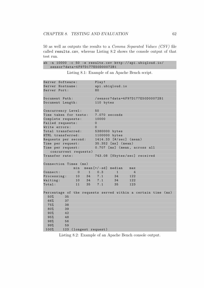
CHAPTER 8. TESTING AND EVALUATION 62
50 as well as outputs the results to a Comma Separated Values (CSV) filecalled results.csv, whereas Listing 8.2 shows the console output of thattest run.ab -n 10000 -c 50 -e results.csv http://api.ubiqloud.io/
sensor?data=4 F97D177E50D00072B1
Listing 8.1: Example of an Apache Bench script.
Server Software: Play!Server Hostname: api.ubiqloud.ioServer Port: 80
Document Path: /sensor?data=4 F97D177E50D00072B1Document Length: 110 bytes
Concurrency Level: 50Time taken for tests: 7.070 secondsComplete requests: 10000Failed requests: 0Write errors: 0Total transferred: 5380000 bytesHTML transferred: 1100000 bytesRequests per second: 1414.33 [#/sec] (mean)Time per request: 35.352 [ms] (mean)Time per request: 0.707 [ms] (mean , across all
concurrent requests)Transfer rate: 743.08 [Kbytes/sec] received
Connection Times (ms)min mean[+/-sd] median max
Connect: 0 1 0.3 1 4Processing: 10 34 7.1 34 122Waiting: 10 34 7.1 34 122Total: 11 35 7.1 35 123
Percentage of the requests served within a certain time (ms)50% 3566% 3775% 3880% 3990% 4295% 4898% 5699% 59
100% 123 (longest request)
Listing 8.2: Example of an Apache Bench console output.

CHAPTER 8. TESTING AND EVALUATION 63
8.3 Testing the Client Interface
Figure 8.1 represents the benchmark results of the tests against the clientinterface (i.e., http://api.ubiqloud.io/object/1/activity/1). As stated, thesame tests were performed against the single UbiQloud instance and thescaled UbiQloud (5 instances). Both tests consisted of 10 identical test runsin order to gain some variance for statistical analysis. The graph lines areconstructed of median values from the 10 test runs.
Figure 8.1: Benchmark results for a single request response time against theclient interface of the single and scaled UbiQloud with 50 concurrent usersand 10000 requests.
The graph clearly shows the superiority of the scaled UbiQloud in responsetime as the amount of requests increase (maximum response time of thescaled UbiQloud for a single request was around 30ms, whereas the corre-sponding value of the single instance was slightly below 150ms). However,the single instance of UbiQloud was capable of responding faster before therequest count increased over 3000. The reason for this is the nature of therequest (i.e., the method called in UbiQloud). The request did not causeany data manipulation on UbiQloud, meaning that UbiQloud did not needmuch time processing the request. With a smaller number of requests, thetime taken in the load balancer to route requests increased the response time

CHAPTER 8. TESTING AND EVALUATION 64
with the scaled UbiQloud. Furthermore, the response time per request withthe single instance increases drastically when the request count reaches over9000. The reason for this might be that the Play! framework reached its limitfor simultaneous requests or the reverse proxy was not configured properly(neither of the two were optimized).
8.4 Testing the Sensor Interface
In these tests, the interface tested was the sensor interface of UbiQloud.In comparison to the client interface tests, the method tested in the sensorinterface manipulated data in UbiQloud, which increased the processing timein the platform. The data sent to UbiQloud was formatted similar to the datasent from the RealSense sensors, meaning that with each request, UbiQloudneeded to parse the data, convert the data to XML, store the data, and pushthe data to the sensor channel. Figure 8.2 represents the results of the sensorinterface tests. The values are again median values from 10 test runs per testcase.
Figure 8.2: Benchmark results for a single request response time against thesensor interface of the single and scaled UbiQloud with 50 concurrent usersand 10000 requests.

CHAPTER 8. TESTING AND EVALUATION 65
Overall, the graph clearly shows that methods manipulating data in Ubi-Qloud need more time for processing (longest response time with the scaledUbiQloud was around 90ms and with the single instance around 410ms).In contrast to the client interface tests, the scaled instance performed bet-ter all the way in the sensor interface test because the time taken in theload balancer is relatively shorter. Furthermore, in these tests the increasein response times with the single UbiQloud towards the end is even moredramatic.
8.5 Evaluation
The performance tests clearly showed that UbiQloud is responsive even withone instance running on the server [64, 66]. In addition, using several Ubi-Qloud instances in parallel showed that the platform scales well and is able toprocess a large number of requests from several clients. Figure 8.3 shows themean count of requests served in a second in all the tests. Without scaling,UbiQloud is able to process nearly 1300 request per second when a client onlyrequests a resource and over 750 requests per second with data manipulationrequests. The corresponding values for the scaled UbiQloud are 2081 requestsper second and 1277 requests per second. However, the tests were performedin a controlled laboratory environment with a high speed wired Internetconnection, which is not often the case in real-world settings. In real-worldsettings, clients often utilize lower speed wireless networks, which in termsaffects the response time. All in all, the tests showed promising results ofthe performance and scalability of the platform, but if the platform wouldbe publicly available, additional testing with additional parameters and indifferent kinds of networks should be performed.

CHAPTER 8. TESTING AND EVALUATION 66
Figure 8.3: Requests per second served during the tests.
Chapter 9
Conclusions
In this Chapter, this Thesis is concluded by first revisiting the research ob-jectives. Then, the main contributions of the author are presented. Next, themain conclusions are drawn based on the results from the literature reviewand empirical validation. Finally, suggestions for future work are discussed.
9.1 Research Objectives Revisited
Before proceeding with the results and conclusions, the research questionsof this Thesis (cf. Chapter 4) are revisited. The research questions of thisThesis were:
Q1: How to integrate server push, Smart Object integration, positioning,and Social Login services under a single cloud-based platform?
Q2: How to transform indoor environments to Smart Spaces by utilizing theexisting plain and smart objects?
Q3: How to seamlessly integrate digital services as part of the everydayphysical activities?
9.2 Main Contributions
The main contributions of this Thesis are as follows:
67

CHAPTER 9. CONCLUSIONS 68
• Requirements analysis for the platform, which is partly conducted bythe Author
• Design of a scalable cloud-based platform offering services for develop-ing real-time, location-aware WoT applications for Smart Spaces, whichhas been solely designed by the Author
• Implementation of a prototype, UbiQloud, whose sole implementer theAuthor has been
• Validation of the design and prototype with performance tests and twosample applications, FeedThroat and InView (both mainly developedby the Author).
9.3 Results
UbiQloud shows that it is possible to develop a cloud-based platform offeringservices related to server push, Web of Things, positioning, and social mediafrom a single entry point. In addition, because of the module-based archi-tecture of the platform, it is relatively easy to add new services and extendexisting ones in the future.
Developing new applications on top of UbiQloud as well as utilizing UbiQloudservices in existing applications should be relatively easy for developers fa-miliar with third-party APIs due to the following reasons: UbiQloud usesstandardized technologies, it is based on the widely used RESTful architec-ture, and it uses well-known security procedures for secure API communica-tion. For a novice developer, the learning curve might be fairly steep, butnot any steeper than using other third-party services.
The sample applications showed (cf. Chapter 7) that UbiQloud can be usedwith real applications in real-world settings and that the implementationmeets the requirements set (Q1). In addition, the functionality and integra-tion to UbiQloud showed that the platform provides a gateway for creatingSmart Spaces (Q2) and that existing objects can be brought as part of theWeb of Things (Q3). Moreover, the performance benchmarks showed thatUbiQloud performs well and can be easily scaled if needed.
All in all, the results suggest that UbiQloud is a powerful and scalable plat-form for developing state-of-the-art Web applications for the Web 3.0 era.There were no indications that the platform would not be suitable for real-world application development. Furthermore, the wide range of services pro-
CHAPTER 9. CONCLUSIONS 69
vided by UbiQloud would ease the development of Web applications andreduce the need to rely on multiple third-party APIs.
9.4 Future Work
There are several possibilities for future work regarding to the work presentedin this Thesis. First of all, the platform could be extended in a variety ofplaces. The amount of social media services supported by the platform couldbe extended to allow users from other services use their existing credentials;the range of sensor-specific drivers could be expanded to offer more usabledata; the coverage of supported protocols for sensor integration could bebroaden (e.g., XMPP and Constrained Application Protocol, CoAP [67]) toallow integration of sensors not capable of communicating with the existinginterfaces.
In addition, the use of XMPP could be increased by supporting, for example,strict client-to-client communication instead of publish/subscribe to allowmore targeted communication and interaction between users. Furthermore,there could be a platform-wide notification channel for broadcasting eventsto better support event-driven architectures.
Furthermore, the APIs could be protected using OAuth 2.0 [68] instead of acustom solution to simplify the communication with the APIs even more. Al-though, the OAuth 2.0 specification is not yet finalized, some of the popularAPIs (e.g., Facebook Graph API) already use it for secure API communica-tion.
Finally, it would be interesting to release UbiQloud as a public service in orderto see how well the platform performs with multiple real-world applicationsdeveloped outside the research community.

Bibliography
[1] A. Taivalsaari and T. Mikkonen. The Web as an Application Platform:The Saga Continues. In Proceedings of the 37th EUROMICRO Confer-ence on Software Engineering and Advanced Applications (SEAA’11),pages 170–174. IEEE, 2011. doi: 10.1109/SEAA.2011.35.
[2] T. Mikkonen and A. Taivalsaari. Reports of the Web’s Death AreGreatly Exaggerated. Journal of Computer, 44(5):30–36, 2011. doi:10.1109/MC.2011.127.
[3] S. Murugesan. Web X.0: A Road Map, volume 1, pages 1–11. Informa-tion Science Reference, 2010.
[4] M. Meeker, S. Devitt, and L. Wu. Internet Trends. Technical re-port, Morgan Stanley, 2010. URL http://www.morganstanley.com/institutional/techresearch/pdfs/Internet_Trends_041210.pdf.
[5] R. Fielding, J. Gettys, J. Mogul, H. Frystyk, L. Masinter, P. Leach,and T. Berners-Lee. Hypertext Transfer Protocol – HTTP/1.1. RFC2616 (Draft Standard), June 1999. URL http://www.ietf.org/rfc/rfc2616.txt. Updated by RFCs 2817, 5785, 6266, 6585.
[6] M. Pohja. Server Push for Web Applications via Instant Messaging.Journal of Web Engineering, 9(3):227–242, 2010.
[7] I. Hickson. HTML5. W3C working draft, W3C, March 2012. URLhttp://www.w3.org/TR/2012/WD-html5-20120329/.
[8] T. Bray, J. Paoli, E. Maler, F. Yergeau, and C. M. Sperberg-McQueen.Extensible Markup Language (XML) 1.0 (Fifth Edition). W3C recom-mendation, W3C, November 2008. URL http://www.w3.org/TR/2008/REC-xml-20081126/.
70
BIBLIOGRAPHY 71
[9] D. Crockford. The application/json Media Type for JavaScript ObjectNotation (JSON). RFC 4627 (Informational), July 2006. URL http://www.ietf.org/rfc/rfc4627.txt.
[10] A. Ginige and S. Murugesan. The essence of web engineering - managingthe diversity and complexity of web application development. Journalof Multimedia, 8(2):22 –25, apr-jun 2001. ISSN 1070-986X. doi: 10.1109/MMUL.2001.917968.
[11] Y. Huang and H. Garcia-Molina. Publish/Subscribe in a Mobile Envi-ronment. Journal of Wireless Networks, 10:643–652, 2004. ISSN 1022-0038.
[12] P. Saint-Andre, K. Smith, and R. Tronçon. XMPP: The DefinitiveGuide. O’Reilly Media, Inc., Sebastobol, CA, the United States of Amer-ica, 2009. ISBN 978-0596521264.
[13] P Saint-Andre. Streaming XML with Jabber/XMPP. IEEE InternetComputing, 9(5):82–89, 2005. URL http://ieeexplore.ieee.org/lpdocs/epic03/wrapper.htm?arnumber=1510608.
[14] P. Saint-Andre. Extensible Messaging and Presence Protocol (XMPP):Core. RFC 6120 (Proposed Standard), March 2011. URL http://www.ietf.org/rfc/rfc6120.txt.
[15] P. Saint-Andre. Extensible Messaging and Presence Protocol (XMPP):Instant Messaging and Presence. RFC 6121 (Proposed Standard), March2011. URL http://www.ietf.org/rfc/rfc6121.txt.
[16] I. Paterson and P. Saint-Andre. XEP-0206: XMPP over BOSH. DraftStandard, July 2010. URL http://xmpp.org/extensions/xep-0206.html.
[17] P. Millard, P. Saint-Andre, and R. Meijer. XEP-0060: Publish-Subscribe. Draft Standard, July 2010. URL http://xmpp.org/extensions/xep-0060.html.
[18] J. Postel. Transmission Control Protocol. RFC 793 (Standard), Septem-ber 1981. URL http://www.ietf.org/rfc/rfc793.txt. Updated byRFCs 1122, 3168, 6093, 6528.
[19] I. Paterson, D. Smith, P. Saint-Andre, and J. Moffitt. XEP-0124:Bidirectional-streams Over Synchronous HTTP (BOSH). Draft Stan-dard, July 2010. URL http://xmpp.org/extensions/xep-0124.html.
BIBLIOGRAPHY 72
[20] I. Fette and A. Melnikov. TheWebSocket Protocol. RFC 6455 (ProposedStandard), December 2011. URL http://www.ietf.org/rfc/rfc6455.txt.
[21] J. Moffit and E. Cestari. An XMPP Sub-protocol for WebSocket.Internet Draft, June 2011. URL http://tools.ietf.org/html/draft-moffitt-xmpp-over-websocket-00.
[22] I. Hickson. The WebSocket API. W3C candidate recommendation,W3C, December 2011. http://www.w3.org/TR/websockets/.
[23] R. Krannenburg. The Internet of Things. A critique of ambient tech-nology and the all-seeing network of RFID. Network Notebooks 02.Institute of Network Cultures, 2008.
[24] Internet of things in 2020, roadmap for the future. Technical report, IN-FSO D.4 Networked Enterprise & RFID INFSO G.2 Micro & Nanosys-tems in co-operation with the Working Group RFID of the ETP EPOSS,May 2008.
[25] D. Guinard, V. Trifa, F. Mattern, and E. Wilde. From the Internetof Things to the Web of Things: Resource Oriented Architecture andBest Practices, chapter 5, pages 97–129. Springer, April 2011. ISBN978-3-642-19156-5.
[26] G. Kortuem, F. Kawsar, V. Sundramoorthy, and D. Fitton. Smart ob-jects as building blocks for the internet of things. IEEE Internet Com-puting, 14(1):44–51, 2010. URL http://oro.open.ac.uk/31631/.
[27] L. Atzori, A. Iera, and G. Morabito. The Internet of Things: ASurvey. Computer Networks, 54(15):2787–2805, 2010. URL http://linkinghub.elsevier.com/retrieve/pii/S1389128610001568.
[28] T. Kawashima, J. Ma, R. Huang, and B. O. Apduhan. GUPSS: AGateway-Based Ubiquitous Platform for Smart Space. 2009 Interna-tional Conference on Computational Science and Engineering, pages213–220, 2009. doi: 10.1109/CSE.2009.265. URL http://ieeexplore.ieee.org/lpdocs/epic03/wrapper.htm?arnumber=5284203.
[29] D. Guinard, V. Trifa, and E. Wilde. A Resource Oriented Ar-chitecture for the Web of Things. Journal of Evolution, pages 1–8, 2010. URL http://ieeexplore.ieee.org/xpls/abs_all.jsp?arnumber=5678452.

BIBLIOGRAPHY 73
[30] R. T. Fielding. Architectural Styles and the Design of Network-based Software Architectures. PhD thesis, University of Califor-nia, Irvine, 2000. URL http://citeseerx.ist.psu.edu/viewdoc/download?doi=10.1.1.91.9164\&rep=rep1\&type=pdf.
[31] L. Reyero and G. Delisle. A Pervasive Indoor-Outdoor PositioningSystem. Journal of Networks, 3(8):70–83, 2008. URL http://www.academypublisher.com/ojs/index.php/jnw/article/view/1056.
[32] H. Liu, H. Darabi, P. Banerjee, and J. Liu. Survey of Wireless IndoorPositioning Techniques and Systems, 2007. URL http://ieeexplore.ieee.org/lpdocs/epic03/wrapper.htm?arnumber=4343996.
[33] A. Popescu. Geolocation API Specification. W3C proposed rec-ommendation, W3C, May 2012. http://www.w3.org/TR/2012/PR-geolocation-API-20120510/.
[34] A. Mayfield. What is social media? Journal of Networks, 1.4:36, 2008. URL http://www.icrossing.co.uk/fileadmin/uploads/eBooks/What_is_Social_Media_iCrossing_ebook.pdf.
[35] How Many Social Networking Websites AreThere? URL http://howmanyarethere.net/how-many-social-networking-websites-are-there/.
[36] H. Oh and S. Jin. The Security Limitations of SSO in OpenID. 2008 10thInternational Conference on Advanced Communication Technology, 3:1608–1611, 2008. URL http://ieeexplore.ieee.org/xpl/freeabs_all.jsp?arnumber=4494089.
[37] M. N. Ko, G. P. Cheek, M. Shehab, and C. North. CONNECTSERVICES. Journal of Computer, 43(8):37–43, 2010. URL http://ieeexplore.ieee.org/xpls/abs_all.jsp?arnumber=5551044.
[38] M. Böhm, S. Leimeister, C. Riedl, and H. Krcmar. Cloud Com-puting and Computing Evolution. In Cloud Computing Technolo-gies Business Models Opportunities and Challenges, pages 1–28.CRC Press, 2010. URL http://www.theseus.joint-research.org/assets/Wissenschaftliche-Publikationen/BoehmEtAl2009c.pdf.
[39] S. P. Mirashe and N. V. Kalyankar. Cloud Computing. Communicationsof the ACM, 51(7):9, 2010. URL http://arxiv.org/abs/1003.4074.
BIBLIOGRAPHY 74
[40] L. Savu. Cloud Computing Deployment models, delivery models, risksand research challanges. Information Security, 2011.
[41] P. Ljungstrand, J. Redström, and L. E. Holmquist. WebStickers: Us-ing Physical Tokens to Access, Manage and Share Bookmarks to theWeb. In Proceedings of DARE 2000 Designing Augmented Reality En-vironments, pages 23–31. ACM Press, 2000. doi: 10.1145/354666.354669. URL http://portal.acm.org/citation.cfm?id=354669\&coll=ACM\&dl=ACM\&CFID=64850236\&CFTOKEN=86024593\#.
[42] V. Trifa, D. Guinard, V. Davidovski, A. Kamilaris, and I. Delchev. WebMessaging for Open and Scalable Distributed Sensing Applications. WebEngineering, 6189:129–143, 2010. URL http://www.springerlink.com/index/G21NG6L3T60147H7.pdf.
[43] M. Blackstock, N. Kaviani, R. Lea, and A. Friday. MAGIC Broker 2:An open and extensible platform for the Internet of Things. Computing,(Nov. 29 2010-Dec. 1 2010):1–8, 2010. URL http://dx.doi.org/10.1109/IOT.2010.5678443.
[44] T. Springer, D. Schuster, I. Braun, J. Janeiro, M. Endler, andA. Loureiro. A Flexible Architecture For Mobile Collaboration Ser-vices. Proceedings of the ACMIFIPUSENIX international middle-ware conference companion on Middleware 08, page 118, 2008. doi:10.1145/1462735.1462770. URL http://portal.acm.org/citation.cfm?doid=1462735.1462770.
[45] R. Lübke, D. Schuster, and A. Schill. MobilisGroups: Location-basedgroup formation in Mobile Social Networks. Computer Networks, pages502–507, 2011. doi: 10.1109/PERCOMW.2011.5766941. URL http://ieeexplore.ieee.org/xpls/abs\_all.jsp?arnumber=5766941.
[46] D. Schuster, T. Springer, and A. Schill. Service-based develop-ment of mobile real-time collaboration applications for Social Net-works. 2010 8th IEEE International Conference on Pervasive Com-puting and Communications Workshops PERCOM Workshops, pages232–237, 2010. URL http://ieeexplore.ieee.org/lpdocs/epic03/wrapper.htm?arnumber=5470662.
[47] N. Jansen. Design and Implementation of a Web Gateway for MobileCollaboration Services. Master’s thesis, TU Dresden, 2011.
[48] Pusher. URL http://pusher.com/. [last checked: June 7, 2012].
BIBLIOGRAPHY 75
[49] Facebook. URL http://www.facebook.com. [last checked: May 7,2012].
[50] LogicAlloy ALE Server. URL http://www.logicalloy.com/. [lastchecked: May 7, 2012].
[51] M. Gudgin, M. Hadley, N. Mendelsohn, Y. Lafon, J.-J. Moreau, A. Kar-markar, and H. Nielsen. SOAP Version 1.2 Part 1: Messaging Frame-work (Second Edition). W3C recommendation, W3C, April 2007.http://www.w3.org/TR/soap12-part1/.
[52] Cosm. URL https://cosm.com/. [last checked: May 7, 2012].
[53] Qubulus. URL http://www.qubulus.com/. [last checked: June 7, 2012].
[54] Gigya. URL http://www.gigya.com/. [last checked: June 7, 2012].
[55] Janrain. URL http://janrain.com/. [last checked: June 7, 2012].
[56] 4D-Space. URL http://mide.aalto.fi/en/4D-Space. [last checked:June 7, 2012].
[57] P. Ojanen, P. Vuorimaa, P. Saarikko, and S. Uotinen. Sharing andBrowsing Social Objects in Physical Space within Close-Knit Groups.In 1st International Workshop on Mobile Interaction in Retail Environ-ments, 2011.
[58] P. Ojanen, P. Vuorimaa, P. Saarikko, and S. Uotinen. Ubeel: Gener-ating Local Narratives for Public Displays from Tagged and AnnotatedVideo Content. 2011. URL http://ftp.informatik.rwth-aachen.de/Publications/CEUR-WS/Vol-720/.
[59] S. Wellman. Google Lays Out Its Mobile User Experience Strategy- mobility Blog, April 11 2007. URL http://www.informationweek.com/blog/229216268. [last checked: June 7, 2012].
[60] Play! Framework. URL http://www.playframework.org/. [lastchecked: June 7, 2012].
[61] Openfire. URL http://www.igniterealtime.org/projects/openfire/. [last checked: June 7, 2012].
[62] MySQL. URL http://www.mysql.com/. [last checked: June 7, 2012].

BIBLIOGRAPHY 76
[63] Signature Version 2 Signing Process. Amazon Web Services.URL http://docs.amazonwebservices.com/general/latest/gr/signature-version-2.html. [last checked: June 7, 2012].
[64] Benchmarking APIs using PerfectAPI vs Express.js vsRestify.js. URL http://blog.perfectapi.com/2012/benchmarking-apis-using-perfectapi-vs-express.js-vs-restify.js/. [last checked: June 7, 2012].
[65] ab - Apache HTTP server benchmarking tool. URL http://httpd.apache.org/docs/2.0/programs/ab.html. [last checked: June 7,2012].
[66] S. Ahuja and J.-E. Yang. Performance Evaluation of Java Web Services:A Developer’s Perspective. Communications and Network, 2:200–206,2010.
[67] Z. Shelby, K. Hartke, C. Bormann, and B. Frank. Constrained Ap-plication Protocol (CoAP). Internet Draft, March 2012. URL http://datatracker.ietf.org/doc/draft-ietf-core-coap/.
[68] D. Recordon and D. Hardt. The OAuth 2.0 Authorization Frame-work. Internet Draft, May 2012. URL http://tools.ietf.org/html/draft-ietf-oauth-v2-26.