ubiquitous and wearable vision systems -...
TRANSCRIPT

Ubiquitous and Wearable Vision Systems
Takashi MatsuyamaGraduate School of Informatics
Kyoto UniversitySakyo, Kyoto, 606-8501, Japan
Capturing multi-view images by a group of spatially distributed cameras is one of the most usefuland practical methods to extend utilities and overcome limitations of a standard pinhole camera: limitedsize of visual field and degeneration of 3D information. This paper gives an overview of our researchactivities on multi-view image analysis. First we address a ubiquitous vision system, where a group ofnetwork-connected active cameras are embedded in the real world to realize 1) wide-area dynamic 3Dscene understanding and 2) versatile 3D scene visualization. To demonstrate utilities of the system, wedeveloped a cooperative distributed active object tracking system and a 3D video generation system. Thelatter half of the paper discusses a wearable vision system, where multiple active cameras are placed nearbyaround human eyes to share the visual field. To demonstrate utilities of the system, we developed systemsfor 1) real time accurate estimation of 3D human gaze point, 2) 3D digitization of a hand-held object,and 3) estimation of 3D human motion trajectory.
1 Introduction
Capturing multi-view images by a group of spatially distributed cameras is one of the most useful andpractical methods to extend utilities and overcome limitations of a standard pinhole camera: limited sizeof visual field and degeneration of 3D information.
Figure 1 illustrates three typical types of multi-view camera arrangements:
(1) Parallel View : for wide area stereo vision (e.g. capturing 100m race at the Olympic game)
(2) Convergent View : for detailed 3D human action observation (e.g. digital archive of traditionaldances)
(3) Divergent View : for omnidirectional panoramic scene observation
This paper gives an overview of our research activities on multi-view image analysis. Following abrief introduction of our specialized active camera, the paper addresses a convergent view multi-camerasystem, where a group of network-connected active cameras are embedded in the real world to realize 1)wide-area dynamic 3D scene understanding and 2) versatile 3D scene visualization[1]. We may call suchsystem a ubiquitous vision system. Based on this scheme, we developed a cooperative distributed active
(a) Parallel View (c) Divergent View(b) Convergent View
Figure 1: Types of multi-view camera arrangements.
i
Anomalous Regions
Generated Image
Input Image
Appearance Plane
ParameterPan, Tilt, Zoom
(Background Image Database)
Camera Action
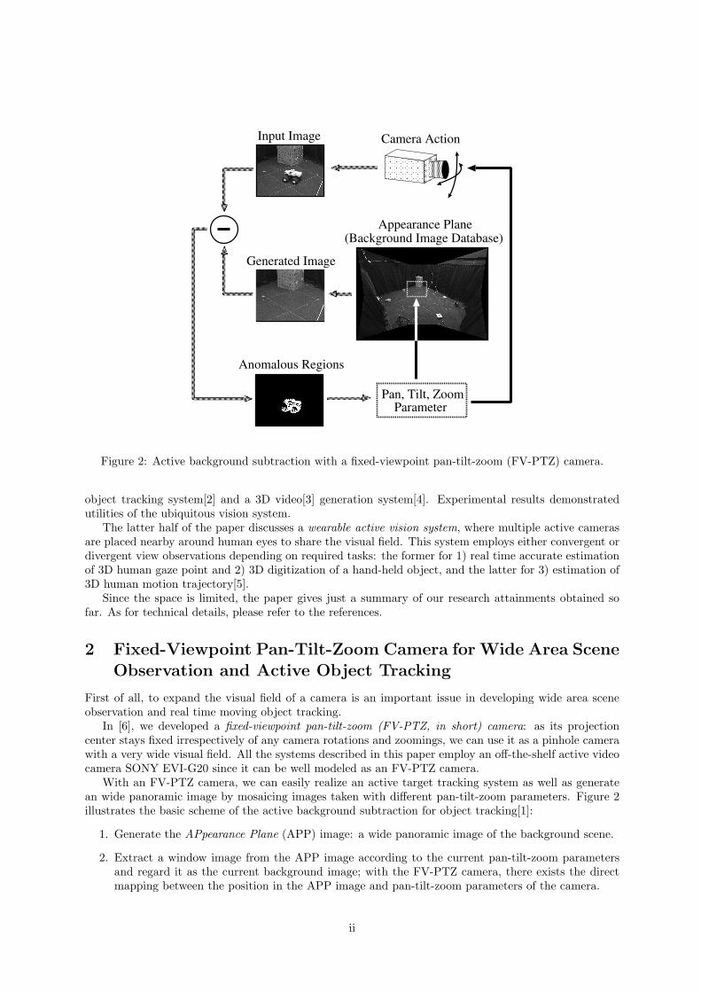
Figure 2: Active background subtraction with a fixed-viewpoint pan-tilt-zoom (FV-PTZ) camera.
object tracking system[2] and a 3D video[3] generation system[4]. Experimental results demonstratedutilities of the ubiquitous vision system.
The latter half of the paper discusses a wearable active vision system, where multiple active camerasare placed nearby around human eyes to share the visual field. This system employs either convergent ordivergent view observations depending on required tasks: the former for 1) real time accurate estimationof 3D human gaze point and 2) 3D digitization of a hand-held object, and the latter for 3) estimation of3D human motion trajectory[5].
Since the space is limited, the paper gives just a summary of our research attainments obtained sofar. As for technical details, please refer to the references.
2 Fixed-Viewpoint Pan-Tilt-Zoom Camera for Wide Area SceneObservation and Active Object Tracking
First of all, to expand the visual field of a camera is an important issue in developing wide area sceneobservation and real time moving object tracking.
In [6], we developed a fixed-viewpoint pan-tilt-zoom (FV-PTZ, in short) camera: as its projectioncenter stays fixed irrespectively of any camera rotations and zoomings, we can use it as a pinhole camerawith a very wide visual field. All the systems described in this paper employ an off-the-shelf active videocamera SONY EVI-G20 since it can be well modeled as an FV-PTZ camera.
With an FV-PTZ camera, we can easily realize an active target tracking system as well as generatean wide panoramic image by mosaicing images taken with different pan-tilt-zoom parameters. Figure 2illustrates the basic scheme of the active background subtraction for object tracking[1]:
1. Generate the APpearance Plane (APP) image: a wide panoramic image of the background scene.
2. Extract a window image from the APP image according to the current pan-tilt-zoom parametersand regard it as the current background image; with the FV-PTZ camera, there exists the directmapping between the position in the APP image and pan-tilt-zoom parameters of the camera.
ii

Agency2
Agency1
Object
Object
AVA1 AVA2 AVA1 AVA2
AVA3AVA4AVA3AVA4
image camera
Detect!
Navigated!
Navigated! Cooperating!
Cooperating! Cooperating!
Agency
Object1
Object2
targetChange
AVA1 AVA2
AVA3AVA4
(a) (b) (c)
Figure 3: Basic scheme for cooperative tracking: (a) Gaze navigation, (b) Cooperative gazing, (c) Adap-tive target switching.
3. Compute difference between the current background image and an observed image.
4. If anomalous regions are detected in the difference image, select one and control the camera param-eters to track the selected target.
Based on this scheme, we developed a real-time active moving object tracking system, where a robustbackground subtraction method[7] and a sophisticated real-time camera control method[8] were employed.
3 Tracking and 3D Digitization of Objects by a Ubiquitous Vi-sion System
3.1 Cooperative multi-target tracking by communicating active vision agents
Since the observation from a single viewpoint cannot give us explicit 3D scene information or avoidocclusion, we developed a multi-viewpoint camera system (i.e. convergent view multi-camera system),where a group of network connected FV-PTZ cameras are distributed in a wide area scene. Each camerais controlled by its corresponding PC, which exchanges observed data with each other to track objectsand measure their 3D information. We call such network-connected PC with an active camera ActiveVision Agent (AVA, in short).
Assuming that the cameras are calibrated and densely distributed over the scene so that their visualfields are well overlapping with each other, we developed a cooperative multi-target tracking system bya group of communicating AVAs[2].
Figure 3 illustrates the basic tasks conducted by the cooperations among AVAs:
1. Initially, each AVA independently searches for a target that comes into its observable area.
2. If an AVA detects a target, it navigates the gazes of the other AVAs towards that target (Figure 3(a)).
3. A group of AVAs which gaze at the same target form what we call an Agency and keep measuringthe 3D information of the target from multi-view images (Figure 3 (b)). Note that while someAVAs are tracking an object, others are still searching for new objects.
4. Depending on target locations in the scene, each AVA dynamically changes its target (Figure 3 (c)).
To verify the effectiveness of the proposed system, we conducted experiments of multiple humantracking in a room (about 5m × 5m). The system consists of ten AVAs. Each AVA is implemented on anetwork-connected PC (Pentium III 600MHz × 2) with an FV-PTZ camera (SONY EVI-G20).
iii

AVA2: 2-a 2-b 2-c 2-d 2-e 2-f 2-g 2-h 2-i
AVA5: 5-a 5-b 5-c 5-d 5-e 5-f 5-g 5-h 5-i
AVA9: 9-a 9-b 9-c 9-d 9-e 9-f 9-g 9-h 9-i
AVA1
AVA2 AVA3
AVA4
(a) (b) (c) (d) (e) (f) (g) (h) (i)time
Figure 4: Experimental results.
In the experiment shown in Figure 4, the system tracked two people. Target1 first came into the sceneand after a while, target2 came into the scene. Both targets then moved freely. The upper three rows inFigure 4 show the partial image sequences observed by AVA2, AVA5 and AVA9, respectively. The imageson the same column were taken at almost the same time. The regions enclosed by black and gray linesin the images show the detected regions corresponding to target1 and target2 respectively. Note thatthe image sequences in Figure 4 are not recorded ones but captured real-time according to the targetmotions.
The bottom row in Figure 4 shows the dynamic cooperation process conducted by ten AVAs. Whitecircles mean that AVAs are in the target search mode, while black and gray circles indicate AVAs aretracking target1 or target2 forming agency1 or agency2, respectively. Black and gray squares indicatecomputed locations of target1 and target2 respectively, toward which gazing lines from AVAs are directed.
The system worked as follows. Note that (a)-(i) below denote the situations illustrated in Figure 4.
(a) : Initially, each AVA searched for an object independently.
(b) : AVA5 first detected target1, and after the gaze navigation of the other AVAs, agency1 was formed.
(c) : After a while, all AVAs except AVA5 were tracking target1, since AVA5 had switched its mode fromtracking to searching, depending the target motion.
(d) : Then, AVA5 detected a new target, target2, and generated agency2.
(e) : The agency restructuring protocol (i.e. adaptive target switching) balanced the numbers of memberAVAs in agency1 and agency2. Note that AVA9 and AVA10 were searching for still new objects.
(f) : Since two targets came very close to each other and no AVA could distinguish them, the agencyunification protocol merged agency2 into agency1.
(g) : When the targets got apart, agency1 detected a ’new’ target. Then, it activated the agencyspawning protocol to generate agency2 again for target2.
(h) : Target1 was going out of the scene.
(i) : After agency1 was eliminated, all the AVAs except AVA4 came to track target2.
iv

Myrinet
Figure 5: PC cluster for real-time active3D object shape reconstruction. Figure 6: Captured multi-viewpoint images
These experiments proved that the cooperative target tracking by a group of multi-viewpoint activecameras is very effective to cope with unorganized dynamic object behaviors.
3.2 Generation of high fidelity 3D video
With the above mentioned tracking system, we can capture convergent multi-view video data of a mov-ing object. To make full use of the captured video data, we developed a system for generating 3Dvideo[4][9][10].
3D video[3] is NOT an artificial CG animation but a real 3D movie recording the full 3D shape,motion, and precise surface color & texture of real world objects. It enables us to observe real objectbehaviors from any viewpoints as well as to see pop-up 3D object images. Such new featured imagemedium will promote wide varieties of personal and social human activities: communication (e.g. 3DTV phone), entertainment (e.g. 3D game and 3D TV), education (e.g. 3D animal picture books), sports(e.g. sport performance analysis), medicine (e.g. 3D surgery monitoring), culture (e.g. 3D archive oftraditional dances), and so on.
So far we developed
1. PC cluster system with distributed active cameras for real-time 3D shape reconstruction
2. Dynamic 3D mesh deformation method for obtaining accurate 3D object shape
3. Texture mapping algorithm for high fidelity visualization
4. User friendly 3D video editing system
3.2.1 System organization
Figure 5 illustrates the architecture of our real-time active 3D object shape reconstruction system. Itconsists of
• PC cluster: 30 node PCs (dual Pentium III 1GHz) are connected through Myrinet, an ultra highspeed network (full duplex 1.28Gbps), which enables us to implement efficient parallel processingon the PC cluster.
• Distributed active video cameras: Among 30, 25 PCs have Fixed-Viewpoint Pan-Tilt (FV-PT)cameras, respectively, for active object tracking and imaging.
v

Voxel data
Marching CubesMethod
Texture Mapping
Patch data
3D video
......
......
Volume Intersection
Silhouette Extraction
Figure 7: 3D video generation process
Figure 6 shows a snapshot of multi-view object video data captured by the system. Note that sincethe above mentioned PC cluster is our second generation system and has just become in operation, alltest data used in this paper are those taken by the first generation system (16PCs and 12 cameras)[9].We have verified that the second generation system can generate much more high quality 3D video inmuch less computation time. Experimental results by the second generation system will be publishedsoon.
3.2.2 Processing scheme of 3D video generation
Figure 7 illustrates the basic process of generating a 3D video frame in our system:(1) Synchronized Multi-View Image Acquisition: A set of multi-view object images are taken
simultaneously (top row in Figure 7).(2) Silhouette Extraction: Background subtraction is applied to each captured image to generate
a set of multi-view object silhouettes (second top row in Figure 7).(3) Silhouette Volume Intersection: Each silhouette is back-projected into the common 3D space
to generate a visual cone encasing the 3D object. Then, such 3D cones are intersected with each otherto generate the visual hull of the object (i.e. the voxel representation of the rough object shape) (thirdbottom in Figure 7).
To realize real-time 3D volume intersection,
• we first developed the plane-based volume intersection method, where the 3D voxel space is parti-tioned into a group of parallel planes and the cross-section of the 3D object volume on each planeis reconstructed.
vi
(a) (b)
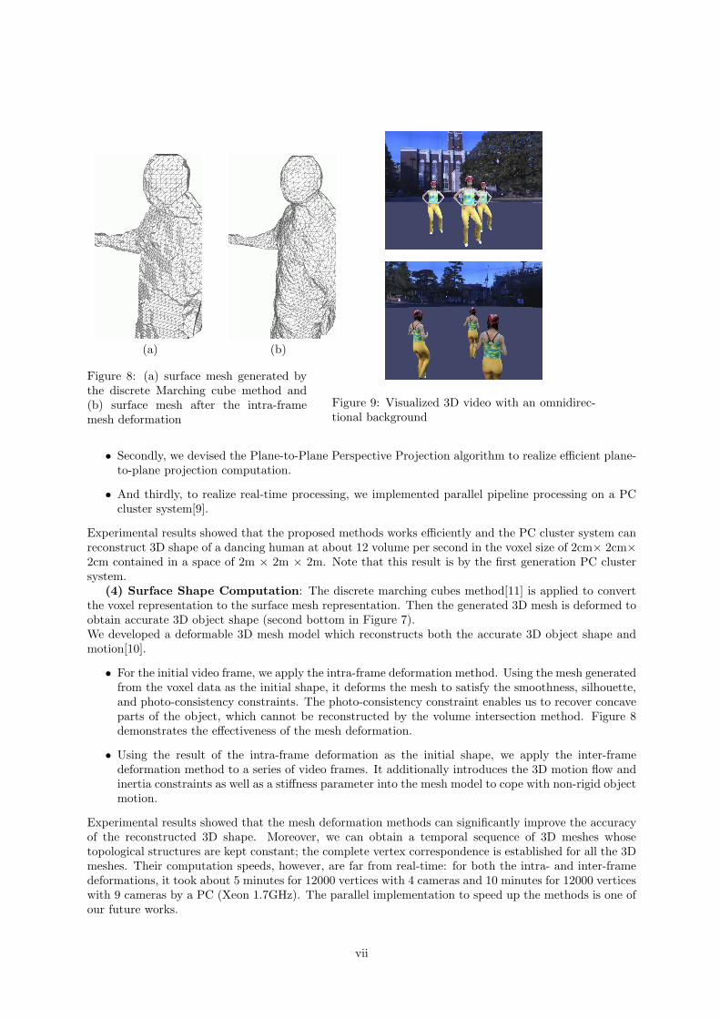
Figure 8: (a) surface mesh generated bythe discrete Marching cube method and(b) surface mesh after the intra-framemesh deformation
Figure 9: Visualized 3D video with an omnidirec-tional background
• Secondly, we devised the Plane-to-Plane Perspective Projection algorithm to realize efficient plane-to-plane projection computation.
• And thirdly, to realize real-time processing, we implemented parallel pipeline processing on a PCcluster system[9].
Experimental results showed that the proposed methods works efficiently and the PC cluster system canreconstruct 3D shape of a dancing human at about 12 volume per second in the voxel size of 2cm× 2cm×2cm contained in a space of 2m × 2m × 2m. Note that this result is by the first generation PC clustersystem.
(4) Surface Shape Computation: The discrete marching cubes method[11] is applied to convertthe voxel representation to the surface mesh representation. Then the generated 3D mesh is deformed toobtain accurate 3D object shape (second bottom in Figure 7).We developed a deformable 3D mesh model which reconstructs both the accurate 3D object shape andmotion[10].
• For the initial video frame, we apply the intra-frame deformation method. Using the mesh generatedfrom the voxel data as the initial shape, it deforms the mesh to satisfy the smoothness, silhouette,and photo-consistency constraints. The photo-consistency constraint enables us to recover concaveparts of the object, which cannot be reconstructed by the volume intersection method. Figure 8demonstrates the effectiveness of the mesh deformation.
• Using the result of the intra-frame deformation as the initial shape, we apply the inter-framedeformation method to a series of video frames. It additionally introduces the 3D motion flow andinertia constraints as well as a stiffness parameter into the mesh model to cope with non-rigid objectmotion.
Experimental results showed that the mesh deformation methods can significantly improve the accuracyof the reconstructed 3D shape. Moreover, we can obtain a temporal sequence of 3D meshes whosetopological structures are kept constant; the complete vertex correspondence is established for all the 3Dmeshes. Their computation speeds, however, are far from real-time: for both the intra- and inter-framedeformations, it took about 5 minutes for 12000 vertices with 4 cameras and 10 minutes for 12000 verticeswith 9 cameras by a PC (Xeon 1.7GHz). The parallel implementation to speed up the methods is one ofour future works.
vii

RightCamera
EyeCamera
LeftCamera
Figure 10: Active wearable vision sensor
(5) Texture Mapping: Color and texture on each patch are computed from the observed multi-viewimages (bottom in Figure 7).
We proposed the viewpoint dependent vertex-based texture mapping method to avoid jitters in ren-dered object images which are caused due to the limited accuracy of the reconstructed 3D object shape[4].Experimental results showed that the proposed method can generate almost natural looking object im-ages from arbitrary viewpoints. By compiling a temporal sequence of reconstructed 3D shape data andmulti-view video into a temporal sequence of vertex lists, we can render arbitrary VGA views of 3D videosequence at video rate by an ordinary PC.
By repeating the above process for each video frame, we have a live 3D motion picture.We also developed a 3D video editing system, with which we can copy and arrange a foreground 3D
video object in front of a background omnidirectional video. Figure 9 illustrates a sample sequence of anedited 3D video.
4 Recognition of Human Activities and Surrounding Environ-ments by an Active Wearable Vision System
The ubiquitous vision systems described so far observe people from outside to objectively analyze theirbehaviors. In this section, on the other hand, we introduce a wearable vision system (Figure 10)[12] toobserve and analyze subjective view of a human; viewpoints of cameras are placed nearby around humaneyes and moves with human behaviors. The system is equipped with a pair of FV-PTZ cameras anda gaze-direction detector (i.e. eye camera in Figure 10) to monitor human eye and head movements.Here we address methods to realized the following three functionalities: 1) 3D gaze point detection andfocused target imaging, 2) 3D digitization of a hand-held object, and 3) 3D human motion trajectorymeasurement.
4.1 3D gaze point detection and focused target imaging
Here, we present a method to capture a close-up image of a human focusing object by actively controllingcameras based on 3D gaze point detection.
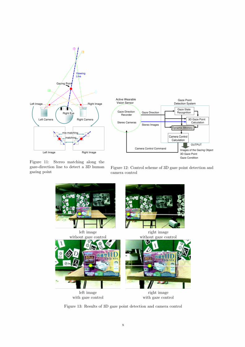
Since the gaze-direction detector equipped can only measure the human gaze direction, we control theFV-PTZ cameras to detect where he/she is looking at in the 3D space. Figure 11 illustrates a method tomeasure a 3D gaze point, which is defined by an intersection point between the gaze-direction line and anobject surface. Assuming the cameras and the gaze-direction detector have been calibrated in advance,the viewing line is projected onto a pair of stereo images captured by the cameras. Then, we apply stereomatching along the pair of the projected lines.
viii

Based on the measured 3D gaze point, we control pan, tilt, and zoom parameters of the active camerasto capture detailed target object images:
• If the human gaze direction is moving, the cameras are zoomed out to capture images of wide visualfield. Pan and tilt are controlled to follow the gaze motion.
• If the human gaze direction is fixed, the camera is zoomed in to capture detailed images of thetarget object. The pan and tilt are controlled to converge toward the 3D gaze point.
We have implemented the above camera control strategy with a dynamic memory architecture[8],with which smooth reactive (without delay) camera control can be realized (Figure 12).
Figure 13 demonstrates the effectiveness of this active camera control. The upper and lower rowsshow pairs of stereo images captured without and with the gaze navigated camera control, respectively.A straight line and a dot in each image illustrate a projected view direction line and a human gazingpoint, respectively.
4.2 3D digitization of a hand-held object
Suppose we are in a department store and checking a coffee cup to buy. In such a situation, we manipulatean object to examine its shape, color, and surface painting from various viewpoints. With the wearablevision system, we developed a method to obtain a full 3D object image from video data captured duringthis human action.
From a viewpoint of human action analysis, first, we classify hand-object relationships into four classesbased on the information human can acquire:Shape Acquisition: Examine the overall object shape, where most of the object silhouette is visible(Figure 14(a)).Surface Texture Acquisition: Examine surface painting, where some parts of the object silhouetteare covered by hands (Figure 14(b)).Haptic Texture Acquisition: Examine surface smoothness, where the object is wrapped by hands andmost of the object surface is invisible (Figure 14(c)).Total Appearance Acquisition: Examine the balance between shape and surface painting, where theobject is turned around and most of object shape and surface painting can be observed (Figure 14(d)).
Then, from a viewpoint of computer vision, the problems to be studied are characterized as follows:
1. Assuming an object is rigid, the wearable vision system can capture convergent multi-view stereoimages of the object; that is, representing the object manipulation process in the object centeredcoordinate system, a pair of stereo cameras are dynamically moved around the object to observeit from different viewpoints. Technically speaking, to determine 3D camera positions and motionin the object centered coordinate system, we have to compute 3D relative position between thecameras and object at each captured video frame as well as conduct stereo camera calibration.
2. While the object shape and position stay fixed in the object centered coordinate system, humanhands change their shapes and positions dynamically to occlude the object. That is, we haveto recover the 3D object shape from convergent multi-view stereo images where the shape andposition of an occluding object changes depending on the viewpoint. We may call this problemshape from multi-view stereo images with viewpoint dependent occlusion, to which we cannot applysuch conventional techniques as shape from silhouettes [13] or space carving [14]..
To solve the problem, we proposed a vacant space carving. That is, we first compute a vacant space,one that is not occupied by any object, from each viewpoint. Then, multiple vacant spaces from differentviewpoints are integrated to generate a 3D object shape. The rationale behind this method is that avacant space from one viewpoint can carve out a space occupied by hands at another viewpoint. Thisremoves the viewpoint dependent occlusion.
The computational algorithm we developed is as follows:1. Capture – A series of stereo images of a hand manipulated object are captured by the wearablevision sensor.2. Feature Point Detection – From each frame of the dynamic stereo images, feature points on the
ix
Gazing Point
Left Image
Right Eye
Left Camera Right Camera
Right Image
ViewingLine
Left Image Right Image
matching
mis-matching
Figure 11: Stereo matching along thegaze-direction line to detect a 3D humangazing point
Active Wearable Vision Sensor
Gaze Direction Recorder
Gaze Direction
Stereo Images
Camera Control Command
Gaze Point Detection System
3D Gaze Point Calculation
Gaze StateRecognition
Camera ControlCalculation
OUTPUT
Images of the Gazing Object 3D Gaze PointGaze Condition
Stereo Cameras
Dynamic Memory
Figure 12: Control scheme of 3D gaze point detection andcamera control
left image right imagewithout gaze control without gaze control
left image right imagewith gaze control with gaze control
Figure 13: Results of 3D gaze point detection and camera control
x

(a) (b) (c) (d)
Figure 14: Categorization of hand-object relationships: (a) Shape acquisition (b) Surface texture acqui-sition (c) Haptic texture acquisition (d) Total appearance acquisition
(a) (b) (c) (d)
Figure 15: 3D digitization of an alien figure: (a) Captured image (b) Silhouette image (c) 3D shape (d)Digitized object
xi

Figure 16: Binocular independentfixation camera control
Figure 17: Geometric configurationin the right camera fixation control.
object surface are detected by Harris Corner Detector [15] and then, the 3D location of the feature pointsare calculated by stereo analysis.3. Camera Motion Recovery – Based on 3D feature point data observed from multiple viewpoints,the 3D camera position and motion in the object centered coordinate system are estimated by a robustICP algorithm [16].4. Depth Map Acquisition – For each viewpoint, a depth map is computed by region based stereoanalysis. Then, the vacant space based on the stereo vision is computed.5. Silhouette Acquisition – For each viewpoint, an object&hand silhouette is computed by backgroundsubtraction. Then, we compute the vacant space based on the silhouette.6. Vacant Space Carving – The 3D block space is carved by a group of vacant spaces computed frommultiple viewpoint to generate a 3D object shape.
Since the wearable vision system can capture video images of the hand manipulation, we can obtaindensely placed multi-view stereo images to generate an accurate 3D object shape.
We applied the method to a complex alien figure as shown in Figure 15(a). Figures 15(b) and (c)illustrate an extracted object&hand silhouette and the result of the vacant space carving, respectively.After mapping the texture, we obtained the 3D digitized object shown in Figure 15(d).
4.3 Estimation of 3D human motion trajectory by binocular independentfixation camera control
Here, we address 3D human motion trajectory estimation using the active wearable vision system. In theprevious two methods, the active cameras work as stereo cameras sharing the visual field with humanto understand what he/she is looking at. In other words, the cameras captured convergent multi-viewimages of a human interested object.
In this research, on the other hand, a pair of active cameras are used to get the 3D surrounding sceneinformation, which enables us to estimate the 3D human motion (i.e. to be specific, camera motion) inthe scene. That is, the cameras capture divergent multi-view images of the scene during human motion.
To estimate the 3D human motion trajectory with a pair of active wearable cameras, we introducedwhat we call the binocular independent fixation camera control (Figure 16): each camera automaticallyfixates its optical axis at a selected scene point (i.e. the fixation point) and keeps the fixation duringhuman motion. This may be called the cross-eyed vision.
Suppose a pair of wearable cameras are calibrated and their optical axes are fixated at a pair ofcorresponding scene points during human motion. Let T and R denote the translation vector androtation matrix describing the human motion between t and t + 1, respectively.
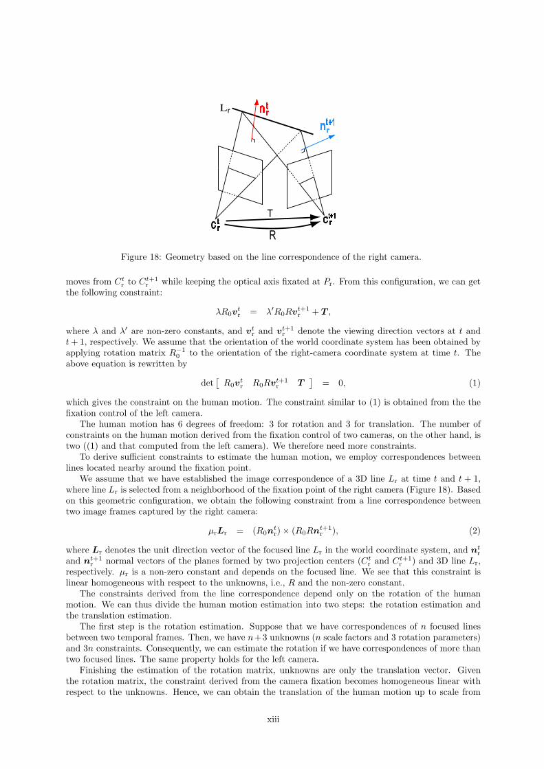
Figure 17 shows the geometric configuration in the right camera fixation control: the projection center
xii
L
C
Figure 18: Geometry based on the line correspondence of the right camera.
moves from Ctr to Ct+1
r while keeping the optical axis fixated at Pr. From this configuration, we can getthe following constraint:
λR0vtr = λ′R0Rvt+1
r + T ,
where λ and λ′ are non-zero constants, and vtr and vt+1
r denote the viewing direction vectors at t andt + 1, respectively. We assume that the orientation of the world coordinate system has been obtained byapplying rotation matrix R−1
0 to the orientation of the right-camera coordinate system at time t. Theabove equation is rewritten by
det[
R0vtr R0Rvt+1
r T]
= 0, (1)
which gives the constraint on the human motion. The constraint similar to (1) is obtained from the thefixation control of the left camera.
The human motion has 6 degrees of freedom: 3 for rotation and 3 for translation. The number ofconstraints on the human motion derived from the fixation control of two cameras, on the other hand, istwo ((1) and that computed from the left camera). We therefore need more constraints.
To derive sufficient constraints to estimate the human motion, we employ correspondences betweenlines located nearby around the fixation point.
We assume that we have established the image correspondence of a 3D line Lr at time t and t + 1,where line Lr is selected from a neighborhood of the fixation point of the right camera (Figure 18). Basedon this geometric configuration, we obtain the following constraint from a line correspondence betweentwo image frames captured by the right camera:
µrLr = (R0ntr) × (R0Rnt+1
r ), (2)
where Lr denotes the unit direction vector of the focused line Lr in the world coordinate system, and ntr
and nt+1r normal vectors of the planes formed by two projection centers (Ct
r and Ct+1r ) and 3D line Lr,
respectively. µr is a non-zero constant and depends on the focused line. We see that this constraint islinear homogeneous with respect to the unknowns, i.e., R and the non-zero constant.
The constraints derived from the line correspondence depend only on the rotation of the humanmotion. We can thus divide the human motion estimation into two steps: the rotation estimation andthe translation estimation.
The first step is the rotation estimation. Suppose that we have correspondences of n focused linesbetween two temporal frames. Then, we have n+3 unknowns (n scale factors and 3 rotation parameters)and 3n constraints. Consequently, we can estimate the rotation if we have correspondences of more thantwo focused lines. The same property holds for the left camera.
Finishing the estimation of the rotation matrix, unknowns are only the translation vector. Giventhe rotation matrix, the constraint derived from the camera fixation becomes homogeneous linear withrespect to the unknowns. Hence, we can obtain the translation of the human motion up to scale from
xiii
two independent fixation points. That is, whenever we estimate the translation of the human motionover two frames, we have one unknown scale factor. The trilinear constraints[17] on corresponding pointsover three frames enable us to adjust the unknown scales with only linear computation.
Comparing our binocular independent fixation camera control with ordinary stereo vision, ours hasthe following advantages:
• Since the image feature matching in our method is conducted between temporally separated imageframes captured from almost the same viewpoint (i.e. by a moving camera), image features to bematched have enough similar appearances to facilitates the matching.
• The similar computational scheme as ours holds when we put cameras at the fixation points inthe scene, which are looking at a person. Since the distance between the fixation points canbe much longer than the baseline length of ordinary stereo cameras and the accuracy in the 3Dmeasurement depends on the baseline length between the cameras, our method can realize moreaccurate 3D position sensing than stereo vision.
To verify the effectiveness of the proposed method, we moved a pair of cameras in a room andestimated their 3D motion trajectory (Figure 19). We marked 35 points on the trajectory and regardedthem as sensing positions during the motion. We then applied the binocular independent fixation cameracontrol at the sensing positions to estimate the right camera motion.
At the starting point of the camera motion, we manually selected a fixation point. During the estima-tion, we manually updated fixation points 8 times; when the camera moves largely and the surroundingscene changes much, we have to change fixation points. We used two focused lines for each camera.Figure 20 shows an example of image pairs captured at a sensing position, where the fixation point (theblack circle) and two focused lines (the thick black lines) are overlaid.
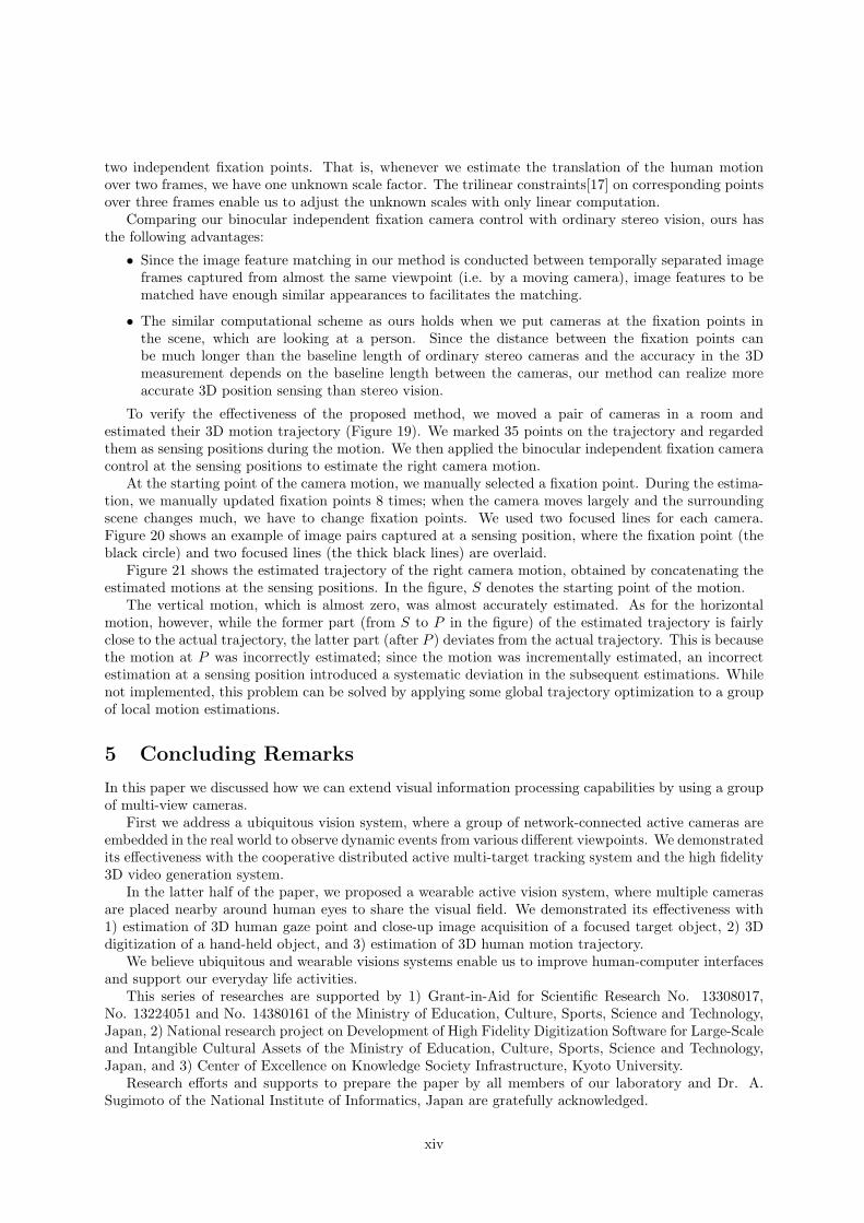
Figure 21 shows the estimated trajectory of the right camera motion, obtained by concatenating theestimated motions at the sensing positions. In the figure, S denotes the starting point of the motion.
The vertical motion, which is almost zero, was almost accurately estimated. As for the horizontalmotion, however, while the former part (from S to P in the figure) of the estimated trajectory is fairlyclose to the actual trajectory, the latter part (after P ) deviates from the actual trajectory. This is becausethe motion at P was incorrectly estimated; since the motion was incrementally estimated, an incorrectestimation at a sensing position introduced a systematic deviation in the subsequent estimations. Whilenot implemented, this problem can be solved by applying some global trajectory optimization to a groupof local motion estimations.
5 Concluding Remarks
In this paper we discussed how we can extend visual information processing capabilities by using a groupof multi-view cameras.
First we address a ubiquitous vision system, where a group of network-connected active cameras areembedded in the real world to observe dynamic events from various different viewpoints. We demonstratedits effectiveness with the cooperative distributed active multi-target tracking system and the high fidelity3D video generation system.
In the latter half of the paper, we proposed a wearable active vision system, where multiple camerasare placed nearby around human eyes to share the visual field. We demonstrated its effectiveness with1) estimation of 3D human gaze point and close-up image acquisition of a focused target object, 2) 3Ddigitization of a hand-held object, and 3) estimation of 3D human motion trajectory.
We believe ubiquitous and wearable visions systems enable us to improve human-computer interfacesand support our everyday life activities.
This series of researches are supported by 1) Grant-in-Aid for Scientific Research No. 13308017,No. 13224051 and No. 14380161 of the Ministry of Education, Culture, Sports, Science and Technology,Japan, 2) National research project on Development of High Fidelity Digitization Software for Large-Scaleand Intangible Cultural Assets of the Ministry of Education, Culture, Sports, Science and Technology,Japan, and 3) Center of Excellence on Knowledge Society Infrastructure, Kyoto University.
Research efforts and supports to prepare the paper by all members of our laboratory and Dr. A.Sugimoto of the National Institute of Informatics, Japan are gratefully acknowledged.
xiv

(a) wide view scene representation (b) top view of the scene
Figure 19: Camera motion trajectory.
(a) left camera image (b) right camera image
Figure 20: Example images acquired for the binocular independent fixation.
(a) 3D representation (b) top-view representation
Figure 21: Estimated trajectory of the camera motion.
xv

References
[1] Matsuyama, T. Cooperative Distributed Vision - Dynamic Integration of Visual Perception, Action,and Communication-, Proc. of Image Understanding Workshop, pp. 365-384, Monterey CA, 1998.
[2] Matsuyama, T. and Ukita, N. Real-Time Multi-Target Tracking by a Cooperative Distributed VisionSystem, Proc. of IEEE, Vol.90, No.7, pp.1136-1150, 2002.
[3] Moezzi, S., Tai, L., and Gerard, P. Virtual View Generation for 3D Digital Video, IEEE Multimedia,pp.18-26, 1997.
[4] Matsuyama, T., Wu, X., Takai, T., and Wada, T. Real-Time Dynamic 3D Object Shape Recon-struction and High-Fidelity Texture Mapping for 3D Video, IEEE Trans. on Circuits and Systemsfor Video Technology, Vol.CSVT-14, No.3, pp.357-369, 2004.
[5] Sumi, K., Sugimoto, A., and Matsuyama, T. Active Wearable Vision Sensor: Recognition of HumanActivities and Environments, Proc. of IEEE International Conference on Informatics Research forDevelopment of Knowledge Society Infrastructure, pp.15-22, Kyoto, 2004.
[6] Wada, T. and Matsuyama, T. Appearance Sphere:Background Model for Pan-Tilt- Zoom Camera,Proc. of 13th ICPR, pp.A-718-A-722, Wienna Austria, 1996.
[7] Matsuyama, T., Ohya, T., and Habe, H. Background Subtraction for Non-Stationary Scenes, Proc.of 4th Asian Conference on Computer Vision, pp.662-667, 2000
[8] Matsuyama, T., Hiura, S., Wada, T., Murase, K., and Yoshioka, A. Dynamic Memory: Architecturefor Real Time Integration of Visual Perception, Camera Action, and Network Communication, Proc.of Comuter Vision and Pattern Recognition Conference, pp.728-735, 2000
[9] Wada, T. and Wu, X. and Tokai, S. and Matsuyama, T. Homography Based Parallel Volume Inter-section: Toward Real-Time Reconstruction Using Active Camera, Proc. of International Workshopon Computer Architectures for Machine Perception, pp.331–339, 2000.
[10] Matsuyama, T. and Wu, X. and Takai, T. and Nobuhara, S. Real-Time 3D Shape Reconstruction,Dynamic 3D Mesh Deformation, and High Fidelity Visualization for 3D Video, International Journalon Computer Vision and Image Understanding, 2004 (in press)
[11] Kenmochi, Y. and Kotani, K. and Imiya, A. Marching Cubes Method with Connectivity, Proc. of1999 International Conference on Image Processing, pp. 361–365, 1999.
[12] Sugimoto, A., Nakayama, A., and Matsuyama, T. Detecting a Gazing Region by Visual Directionand Stereo Cameras, Proc. of the 16th int’l Conf. Pattern Recognition, Vol. III, pp.278-282, 2002.
[13] Hoppe, H., DeRose, T., Duchamp, T., McDonald, J., and Stuetzle, W. Surface reconstruction fromunorganized points, SIGGRAPH ’92, Vol.26, pp.71-78, 1992.
[14] Kutulakos, K.N. and Seitz, S. M. A theory of shape by space carving, IEEE Int’l Conf. on ComputerVision, pp.307-314, 1999.
[15] Harris, C. J. and Stephens, M. A combined corner and edge detector, 4th Alvey Vision Conf.,pp.147–151, 1988
[16] Besl, P.J. and McKey, N.D. A method for registration of 3-D shapes, IEEE Trans. PAMI, Vol.14,No.2, pp.239-256, 1992
[17] Hartley, R. and Zisserman, A. Multiple View Geometry in Computer Vision, Cambridge Univ. Press,2000.
xvi