uc7... · this technical documentation is intended to provide essential information ... 5.6 drive...
TRANSCRIPT
�������������������� ������������� �� ���

������������
������������������ ���������� ��������������������������������������������� ��������������������������������������������������������������������������������������������� ������������������ ����������������������������������������������������������������
���������� ������������������������������������������� ��������!��"#�$�������������������������������������������������%�������������������&����������� #����������'�� #�����������������%�������� ��������������������������&��������������������������������������� �
(������)�
�������� ��������!��"�"��������"���������*+,�'++-.�$�����
������������������� ��������
���������/������0�����)
���������������
�1������������������������������#���������������������������������������������� �����������������2
������ ���� ���� ������������������������������������ �����������!


Foreword
This Technical Documentation is intended to provide essential information about the proper operation and servicing of the Leica EM UC7 Ultramicrotome.
This user manual describes commissioning of the Leica EM UC7 Ultramicrotome, phased testing and adjustment of all components and movement sequences, and restoring the basic functionality.
Service and operating staff must familiarize themselves with all components of the system before commissioning. Particular attention must be paid to the aspect of safety.
This user manual must be retained for future reference.
Texts, schedules and tables may not be copied, reproduced, or divulged to third parties without our express consent.
It should be noted that this Technical Documentation does not constitute a part of any existing, prior agreement or covenant or legal relationship.
All obligations are derived from the purchase agreement, which is also the sole document of record regarding the terms of the warranty. Contractual provisions are not affected by the Technical Documentation.
The documentation issued by the respective suppliers shall apply in addition to this manufacturer's documentation.
In addition, all generally applicable legal and otherwise binding regulations for preventing accidents and protecting the environment must be observed and communicated.
Page 1 Operating Manual Leica EM UC7 09/10
Table of contents 1. Safety Introduction ............................................................................................................4
2. Identification.......................................................................................................................6 2.1 Product ..........................................................................................................................6
2.2 Manufactured by ............................................................................................................6
3. Installation and Set-up.......................................................................................................7 3.1 Transportation and storage condition ............................................................................7
3.2 Installation requirements................................................................................................7 3.2.1 Work area conditions.............................................................................................7 3.2.2 Connections...........................................................................................................8
3.3 Installing, assembling and commissioning.....................................................................8 3.3.1 Unpacking..............................................................................................................8 3.3.2 Installation of the antivibration table ....................................................................12 3.3.3 EM UC7 built in antivibration system...................................................................15 3.3.4 Removal of Transportation Lock..........................................................................15 3.3.5 Mounting the stereo microscope and breath shield.............................................16 3.3.6 Mounting the knife stage .....................................................................................18 3.3.7 Mounting the segment arc ...................................................................................18 3.3.8 Mounting the Peristaltic pump .............................................................................18 3.3.9 Mounting the antistatic electrode for room temperature work (optional) .............19 3.3.10 Electrical connections of the High End control unit .............................................21 3.3.11 Electrical connections of the 7” basic touch screen control unit ..........................22
3.4 Repacking to prevent damage during transportation ...................................................23
3.5 Storage location for the instructions ............................................................................23
4. Operation of the controller..............................................................................................24 4.1 Advanced touch screen control Unit ............................................................................25
4.1.1 Start/Stop.............................................................................................................26 4.1.2. Help .....................................................................................................................26 4.1.3 Cutting window ....................................................................................................26 4.1.4 Speed/Feed .........................................................................................................26 4.1.5 Antistatic ..............................................................................................................27 4.1.6 Knife approach ....................................................................................................27 4.1.7 Return speed .......................................................................................................28 4.1.8 Rocking................................................................................................................28 4.1.9 Illumination ..........................................................................................................28 4.1.10 Reset (total specimen advance indication)..........................................................29 4.1.11 Counter................................................................................................................29 4.1.12 Menu....................................................................................................................34
4.1.12.1 Add and edit user profile ..............................................................................35 4.1.12.2 Add and edit sample ....................................................................................36 4.1.12.3 Add and edit knife / knife segmentation .......................................................37 4.1.12.4 Setup............................................................................................................38
Page 2 Operating Manual Leica EM UC7 09/10
4.1.13 Knife usage (report and upload data to USB stick) .............................................40 4.1.14. Creating a protocol (log book) ............................................................................41
4.2. 7” basic touch screen control Unit ...............................................................................42 4.2.1 Start / Stop...........................................................................................................43 4.2.2 Cutting window ....................................................................................................43 4.2.3 Reset (total specimen advance indication)..........................................................43 4.2.4 Illumination ..........................................................................................................44 4.2.5 Speed / Feed .......................................................................................................44 4.2.6 Antistatic ..............................................................................................................45 4.2.7 Knife approach ....................................................................................................46 4.2.8 Menu....................................................................................................................47
5. Description of the Equipment .........................................................................................49 5.1 Specimen-knife area ....................................................................................................49
5.2 Segment arc ................................................................................................................49
5.3 Specimen transillumination ..........................................................................................50
5.4 Trimming block ............................................................................................................51
5.5 Knife block ...................................................................................................................52
5.6 Drive system ................................................................................................................53
5.7 Stereo carriers .............................................................................................................53
5.8 N-S Position indication of the stage .............................................................................54
6. Technical specifications..................................................................................................55
Page 3 Operating Manual Leica EM UC7 09/10
1. Safety Introduction
The instrument has been so designed and manufactured that the user is not exposed to any danger if the instrument is used as intended. Please read the instruction before use. It is advisable for the user to be trained in the use of the ultramicrotome. The instruments are only allowed to be opened by authorized service personnel. Before opening, the instrument must be disconnected from the electrical mains supply. The instrument is equipped with protected ground. Before connecting it to the local electrical supply make sure that the mains has the required ground and that the instrument is connected to it in accordance with the legal regulations.
Danger of injury when contacting knives
Extremely sharp knives are used for sectioning which can lead to injury when touched. The knife must therefore only be mounted just before sectioning and must be removed from the knife holder after section collection. As long as a knife is in the knife holder, the overhead illumination must be left switched-on. Safety rules must also be observed for the breaking of glass knives. The local regulations must be observed for the disposal of glass knives.
Danger of injury during trimming of specimens
Trimming of specimens can be carried out with razor blades. Doing this, the specimen is clamped in a trimming-block and the excess material removed with a razor blade. Extreme caution is advised when using the razor blade! For safety, Leica recommends the use of a trimming machine.
In certain chapters, a symbol appearing in the margin refers to the function of the respective section of text and is relevant for the operation or maintenance of the system, or indicates important descriptions or additional remarks:
Caution!
This symbol alerts the user to important information which may endanger staff or result in damage to the system if it is ignored.
Note!
This symbol indicates further information relating to a previous explanation, which does not have a safety-critical function. However, it is important to observe this information to ensure that the system functions optimally.
Page 4 Operating Manual Leica EM UC7 09/10

Page 5 Operating Manual Leica EM UC7 09/10

2. Identification
2.1 Product
Leica EM UC7 Ultramicrotome
2.2 Manufactured by
Leica Mikrosysteme GmbH Hernalser Hauptstrasse 219 A-1170 Vienna
Tel.: +43 1 488 99-0 Fax: +43 1 488 99-350
Internet: http:// www.leica-microsystems.com
Page 6 Operating Manual Leica EM UC7 09/10

3. Installation and Set-up
3.1 Transportation and storage condition
The Leica EM UC7 Ultramicrotome is delivered properly packed and in the semi-assembled state. The customer must check the condition of the system upon delivery and file a damage report with the shipping company if the equipment is damaged. The customer must immediately inform the manufacturer of any possible damage in transit.
The system must be positioned upright for transporting.
The overall weight including packaging is approx. 80 kg, with antivibration table approx. 170kg
The packed equipment must be stored in clean, dry areas at temperatures between 5° and 40°C. It must not be exposed to aggressive or corrosive substances.
3.2 Installation requirements
3.2.1 Work area conditions
A certain working distance must be maintained all around the system, to allow the supply connections to be made, and also to enable access for essential servicing activities.
Note!
Minimum of 30 cm.
Page 7 Operating Manual Leica EM UC7 09/10

3.2.2 Connections
The following connections must be assured:
� Electricity supply: 100 – 240 V, 47 – 63 Hz
3.3 Installing, assembling and commissioning
3.3.1 Unpacking
When the instrument is supplied with a working table the EM UC7 is packed in a special carton fastened below the working table. When the EM UC7 is supplied without working table it is housed in a second carton. Cut open the first carton on the top and take out the second carton. Pull off the upper part of the carton and unfold the four lateral walls of its lower part.
1. Cut off the transport ribbons
2. Lift the outer carton above the handle on both sides.
Page 8 Operating Manual Leica EM UC7 09/10
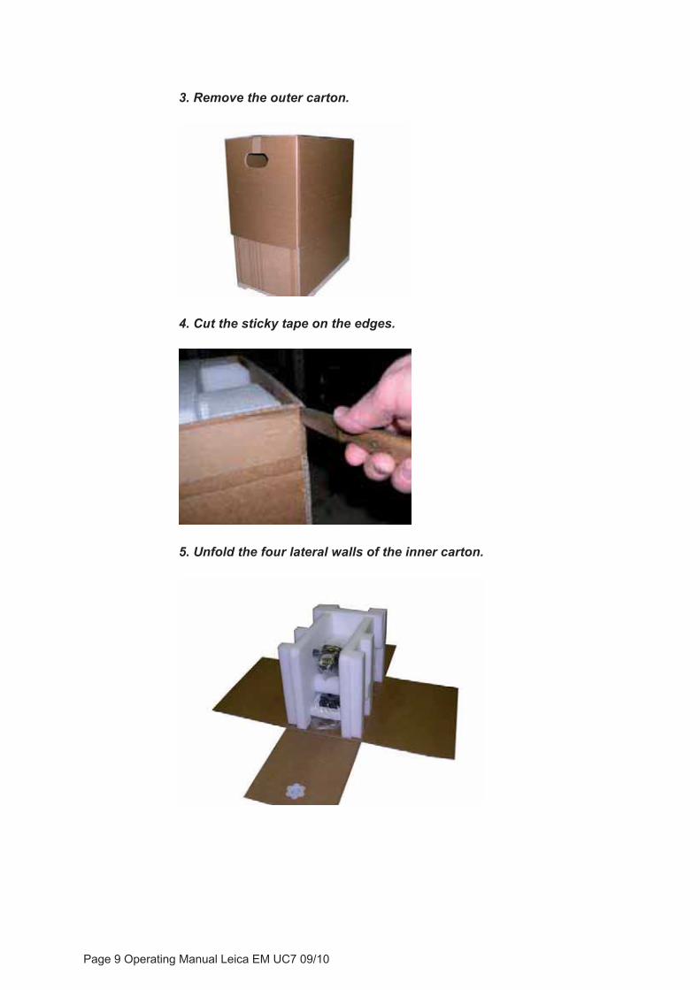
3. Remove the outer carton.
4. Cut the sticky tape on the edges.
5. Unfold the four lateral walls of the inner carton.
Page 9 Operating Manual Leica EM UC7 09/10

6. Remove the rear foam pad.
7. Remove the front foam pad
8. Put the left and right hand pads to the side.
9. Remove plastic bag covering the instrument.
Page 10 Operating Manual Leica EM UC7 09/10
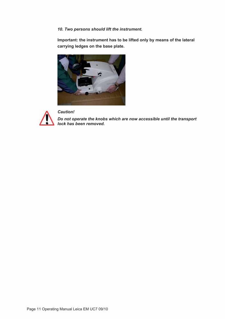
10. Two persons should lift the instrument.
Important: the instrument has to be lifted only by means of the lateral carrying ledges on the base plate.
Caution!Do not operate the knobs which are now accessible until the transport lock has been removed.
Page 11 Operating Manual Leica EM UC7 09/10

3.3.2 Installation of the antivibration table
The instrument table with its special antivibration system is delivered assembled. By using this table the EM UC7 built-in antivibration system will be disabled.
1. Remove the foam transportation lock from the antivibration insert.
2. Remove Allen key and unscrew retaining screws from the cross beam.
3. Mount the shelf on the table cross beam, wider part to the rear.
Page 12 Operating Manual Leica EM UC7 09/10
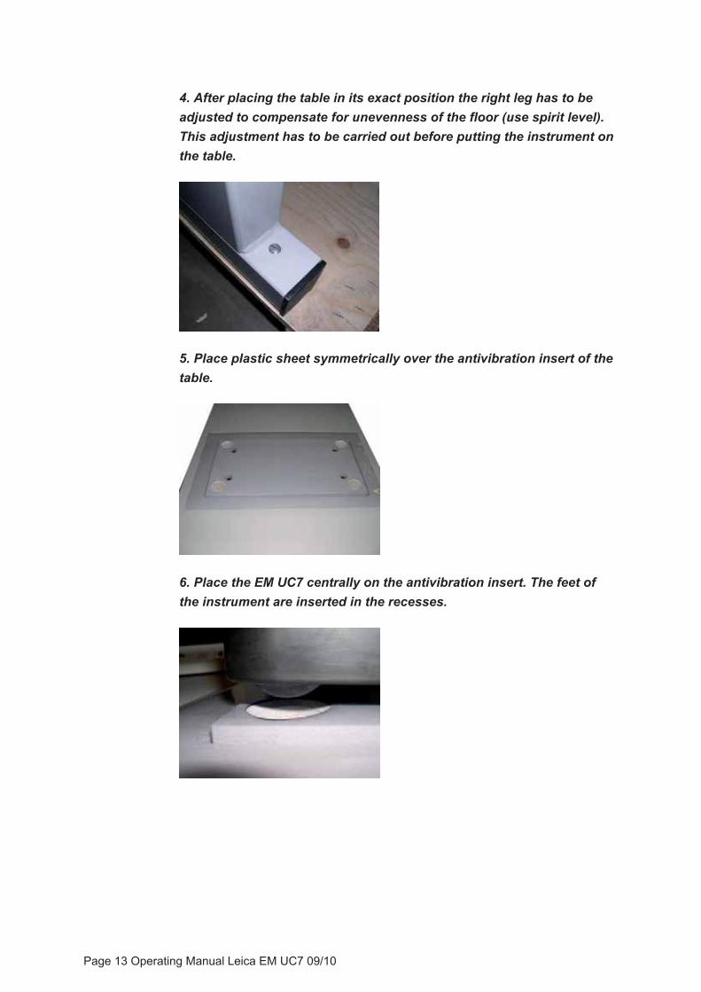
4. After placing the table in its exact position the right leg has to be adjusted to compensate for unevenness of the floor (use spirit level). This adjustment has to be carried out before putting the instrument on the table.
5. Place plastic sheet symmetrically over the antivibration insert of the table.
6. Place the EM UC7 centrally on the antivibration insert. The feet of the instrument are inserted in the recesses.
Page 13 Operating Manual Leica EM UC7 09/10
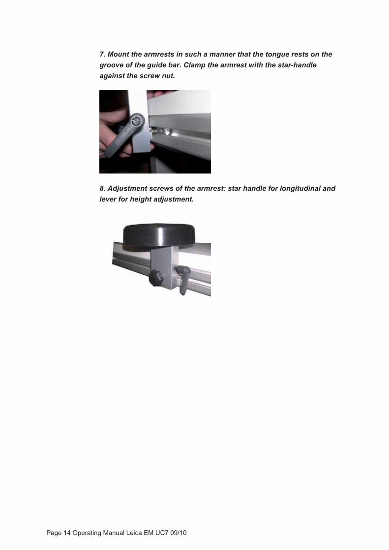
7. Mount the armrests in such a manner that the tongue rests on the groove of the guide bar. Clamp the armrest with the star-handle against the screw nut.
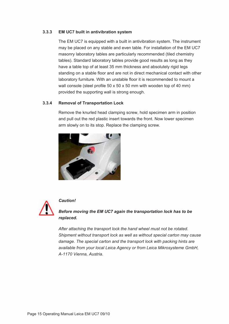
8. Adjustment screws of the armrest: star handle for longitudinal and lever for height adjustment.
Page 14 Operating Manual Leica EM UC7 09/10
3.3.3 EM UC7 built in antivibration system
The EM UC7 is equipped with a built in antivibration system. The instrument may be placed on any stable and even table. For installation of the EM UC7 masonry laboratory tables are particularly recommended (tiled chemistry tables). Standard laboratory tables provide good results as long as they have a table top of at least 35 mm thickness and absolutely rigid legs standing on a stable floor and are not in direct mechanical contact with other laboratory furniture. With an unstable floor it is recommended to mount a wall console (steel profile 50 x 50 x 50 mm with wooden top of 40 mm) provided the supporting wall is strong enough.
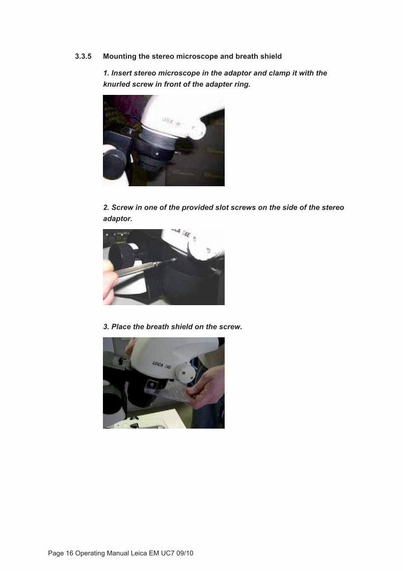
3.3.4 Removal of Transportation Lock
Remove the knurled head clamping screw, hold specimen arm in position and pull out the red plastic insert towards the front. Now lower specimen arm slowly on to its stop. Replace the clamping screw.
Caution!
Before moving the EM UC7 again the transportation lock has to be replaced.
After attaching the transport lock the hand wheel must not be rotated. Shipment without transport lock as well as without special carton may cause damage. The special carton and the transport lock with packing hints are available from your local Leica Agency or from Leica Mikrosysteme GmbH, A-1170 Vienna, Austria.
Page 15 Operating Manual Leica EM UC7 09/10
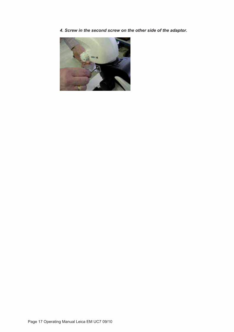
3.3.5 Mounting the stereo microscope and breath shield
1. Insert stereo microscope in the adaptor and clamp it with the knurled screw in front of the adapter ring.
2. Screw in one of the provided slot screws on the side of the stereo adaptor.
3. Place the breath shield on the screw.
Page 16 Operating Manual Leica EM UC7 09/10
4. Screw in the second screw on the other side of the adaptor.
Page 17 Operating Manual Leica EM UC7 09/10
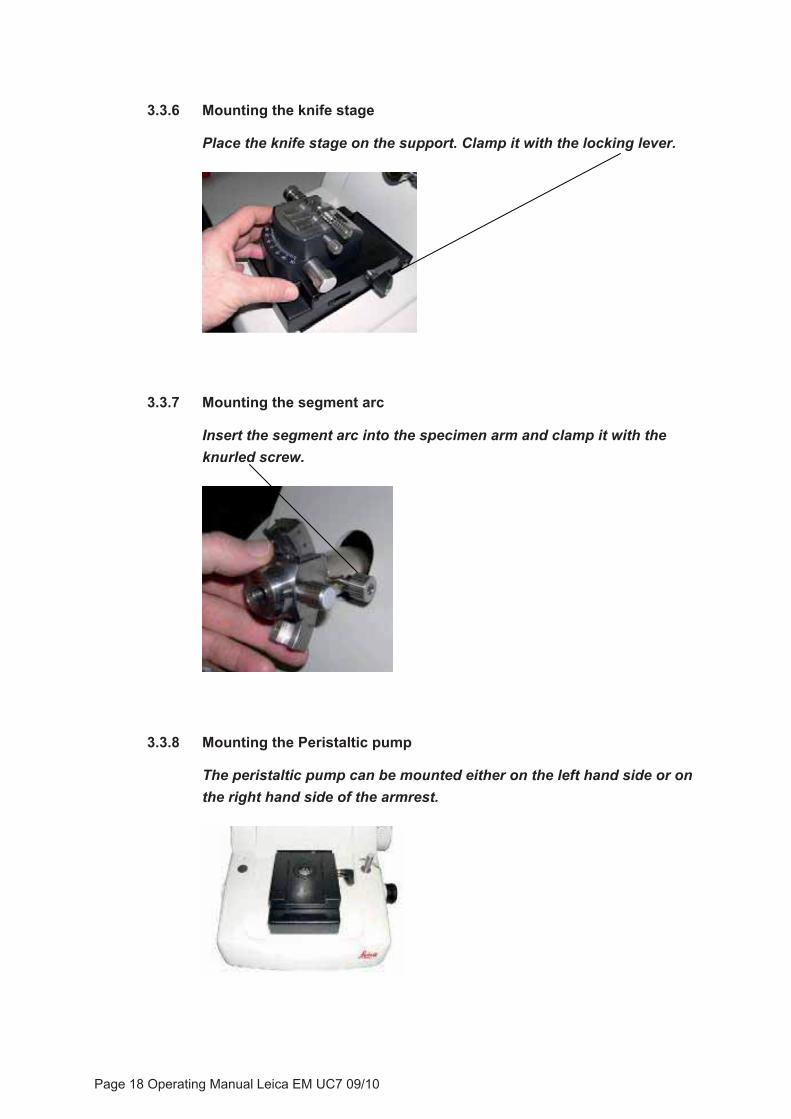
3.3.6 Mounting the knife stage
Place the knife stage on the support. Clamp it with the locking lever.
3.3.7 Mounting the segment arc
Insert the segment arc into the specimen arm and clamp it with the knurled screw.
3.3.8 Mounting the Peristaltic pump
The peristaltic pump can be mounted either on the left hand side or on the right hand side of the armrest.
Page 18 Operating Manual Leica EM UC7 09/10

Remove the armrest from the instrument. Remove the hand wheel of the pump by opening the screw and mount the hand wheel on the other side of the armrest.
3.3.9 Mounting the antistatic electrode for room temperature work (optional)
1. Insert the electrode into the cover of the stereo carrier.
2. Pull the cable of electrode out of the cable channel.
Page 19 Operating Manual Leica EM UC7 09/10

3. Mount the gooseneck on the stereo adapter of the stereo microscope.
4. Secure the gooseneck by tightening the lock nut.
5. Mount the electrode in its adaptor and clamp it on the gooseneck by tightening the Allen screw.
6. Clamp the cable of the electrode with the clip on the gooseneck.
Page 20 Operating Manual Leica EM UC7 09/10
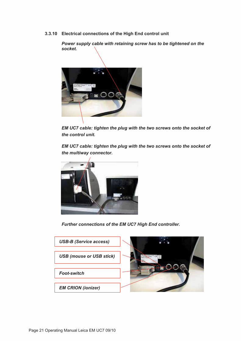
3.3.10 Electrical connections of the High End control unit
Power supply cable with retaining screw has to be tightened on the socket.
EM UC7 cable: tighten the plug with the two screws onto the socket of the control unit.
EM UC7 cable: tighten the plug with the two screws onto the socket of the multiway connector.
Further connections of the EM UC7 High End controller.
USB (mouse or USB stick)
Foot-switch
EM CRION (ionizer)
USB-B (Service access)
Page 21 Operating Manual Leica EM UC7 09/10
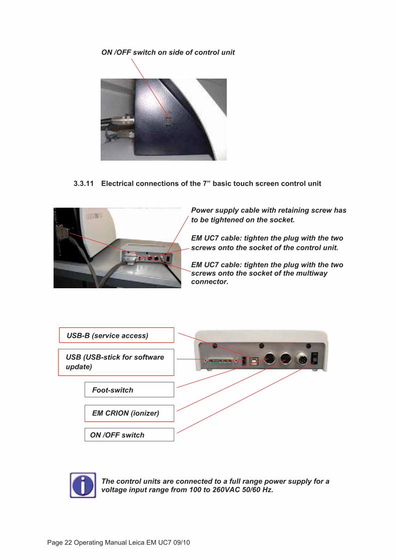
ON /OFF switch on side of control unit
3.3.11 Electrical connections of the 7” basic touch screen control unit
Power supply cable with retaining screw has to be tightened on the socket. EM UC7 cable: tighten the plug with the two screws onto the socket of the control unit. EM UC7 cable: tighten the plug with the two screws onto the socket of the multiway connector.
USB (USB-stick for software update)
USB-B (service access)
Foot-switch
EM CRION (ionizer)
ON /OFF switch
The control units are connected to a full range power supply for a voltage input range from 100 to 260VAC 50/60 Hz.
Page 22 Operating Manual Leica EM UC7 09/10

3.4 Repacking to prevent damage during transportation
The Leica EM UC7 must not be transported unless it is in its original packaging; if it is not, the system may be damaged.
If the system needs to be moved again, disassemble and pack it away by following the instructions listed in 3.3.1 and 3.3.4 Transport Lock in the reverse order.
3.5 Storage location for the instructions
The user manual and associated supplementary documentation (e.g., manual of the stereo microscope) must be kept close to the Leica EM UC7 for fast access.
Page 23 Operating Manual Leica EM UC7 09/10
4. Operation of the controller
Environmental specifications of the touch screen:
Operating temperature: 0°C to 60°C (no condensation)
Operating humidity: Less than 90% RH (no condensation)
Storing temperature: -20°C to 70°C (no condensation)
Storing humidity: Less than 95% RH (no condensation) Cleaning of the touch screen can be carried out with a commercially available damp, lint-free cloth.
After switching on the controller with the rocker switch the initialization process starts. The user interface will appear after about 20 seconds
Page 24 Operating Manual Leica EM UC7 09/10
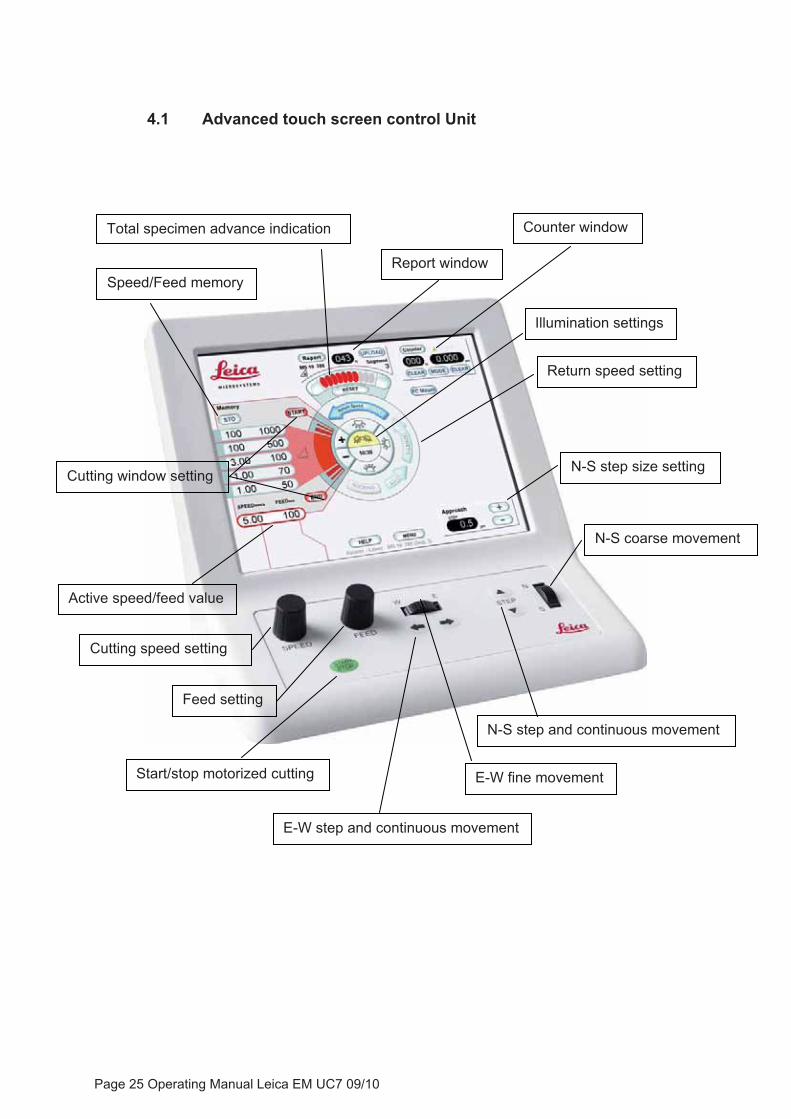
4.1 Advanced touch screen control Unit
N-S coarse movement
N-S step size setting
Return speed setting
Illumination settings
Report window
Active speed/feed value
Cutting speed setting
Feed setting
Start/stop motorized cutting
N-S step and continuous movement
E-W fine movement
E-W step and continuous movement
Cutting window setting
Speed/Feed memory
Total specimen advance indication Counter window
Page 25 Operating Manual Leica EM UC7 09/10
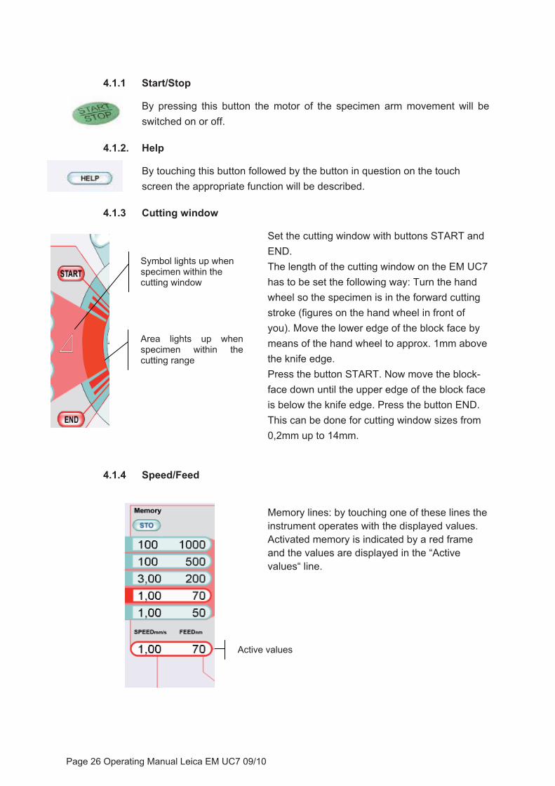
4.1.1 Start/Stop
By pressing this button the motor of the specimen arm movement will be switched on or off.
4.1.2. Help
By touching this button followed by the button in question on the touch screen the appropriate function will be described.
4.1.3 Cutting window
Set the cutting window with buttons START andEND.
Symbol lights up when specimen within the cutting window
The length of the cutting window on the EM UC7 has to be set the following way: Turn the hand wheel so the specimen is in the forward cutting stroke (figures on the hand wheel in front of you). Move the lower edge of the block face by means of the hand wheel to approx. 1mm above the knife edge.
Area lights up when specimen within the cutting range
Press the button START. Now move the block-face down until the upper edge of the block face is below the knife edge. Press the button END. This can be done for cutting window sizes from 0,2mm up to 14mm.
4.1.4 Speed/Feed
Memory lines: by touching one of these lines the instrument operates with the displayed values. Activated memory is indicated by a red frame and the values are displayed in the “Active values“ line.
Active values
Page 26 Operating Manual Leica EM UC7 09/10
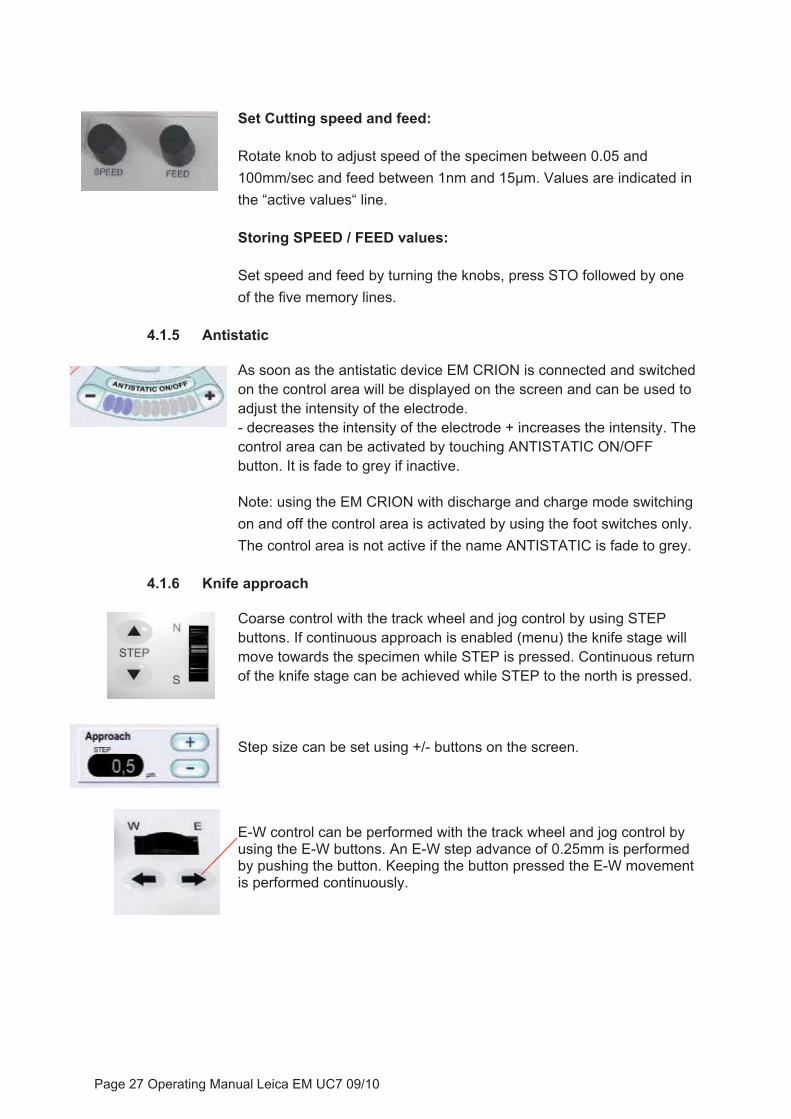
Set Cutting speed and feed:
Rotate knob to adjust speed of the specimen between 0.05 and 100mm/sec and feed between 1nm and 15μm. Values are indicated in the “active values“ line.
Storing SPEED / FEED values:
Set speed and feed by turning the knobs, press STO followed by one of the five memory lines.
4.1.5 Antistatic
As soon as the antistatic device EM CRION is connected and switched on the control area will be displayed on the screen and can be used to adjust the intensity of the electrode. - decreases the intensity of the electrode + increases the intensity. The control area can be activated by touching ANTISTATIC ON/OFF button. It is fade to grey if inactive.
Note: using the EM CRION with discharge and charge mode switching on and off the control area is activated by using the foot switches only. The control area is not active if the name ANTISTATIC is fade to grey.
4.1.6 Knife approach
Coarse control with the track wheel and jog control by using STEP buttons. If continuous approach is enabled (menu) the knife stage will move towards the specimen while STEP is pressed. Continuous return of the knife stage can be achieved while STEP to the north is pressed. Step size can be set using +/- buttons on the screen.
E-W control can be performed with the track wheel and jog control by using the E-W buttons. An E-W step advance of 0.25mm is performed by pushing the button. Keeping the button pressed the E-W movement is performed continuously.
Page 27 Operating Manual Leica EM UC7 09/10
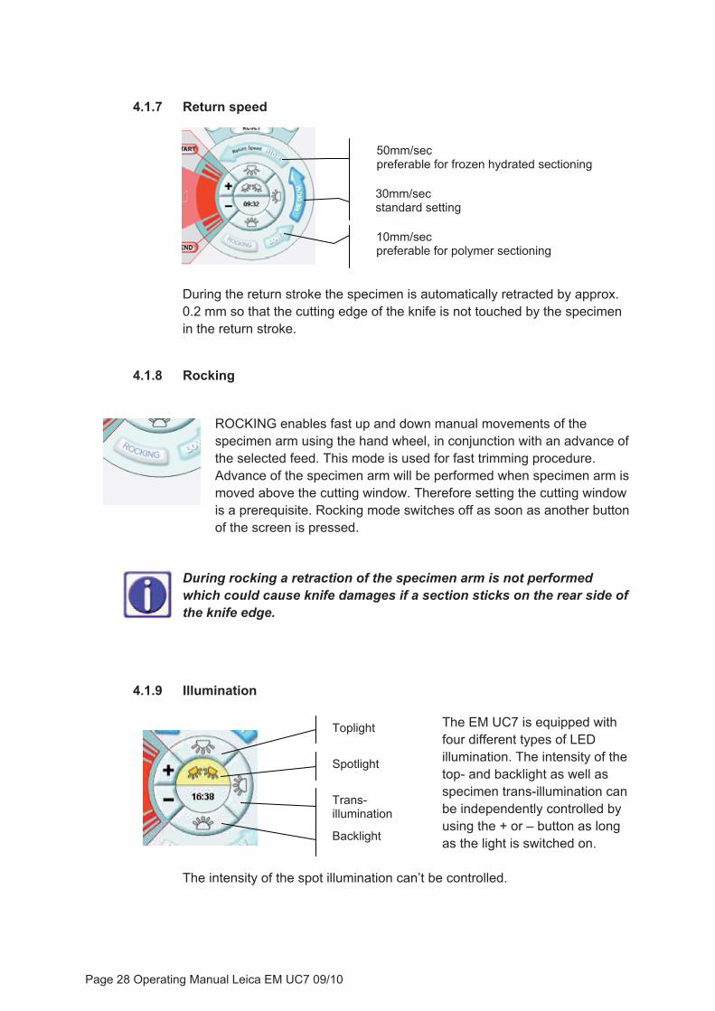
4.1.7 Return speed
10mm/secpreferable for polymer sectioning
50mm/secpreferable for frozen hydrated sectioning
30mm/secstandard setting
During the return stroke the specimen is automatically retracted by approx. 0.2 mm so that the cutting edge of the knife is not touched by the specimen in the return stroke.
4.1.8 Rocking
ROCKING enables fast up and down manual movements of the specimen arm using the hand wheel, in conjunction with an advance of the selected feed. This mode is used for fast trimming procedure. Advance of the specimen arm will be performed when specimen arm is moved above the cutting window. Therefore setting the cutting window is a prerequisite. Rocking mode switches off as soon as another button of the screen is pressed.
During rocking a retraction of the specimen arm is not performed which could cause knife damages if a section sticks on the rear side of the knife edge.
4.1.9 Illumination
The EM UC7 is equipped with four different types of LED illumination. The intensity of the top- and backlight as well as specimen trans-illumination can be independently controlled by using the + or – button as long as the light is switched on.
Trans-illumination
Backlight
Toplight
Spotlight
The intensity of the spot illumination can’t be controlled.
Page 28 Operating Manual Leica EM UC7 09/10

4.1.10 Reset (total specimen advance indication)
Advance indicator and reset control. Each mark indicates the beginning of 20μm of the specimen arm feed. When the last indication mark lights up, an acoustic signal and blinking alerts the operator of the end of the specimen advance. An automated reset will be performed at the end of the advance (200μm). Instant resetting may be carried out at any time by pressing the reset button.
4.1.11 Counter
MODE toggles through the four modes: Section counter and Feed Totalizer, Count down, Integrated E-W measuring system and AutoTrim function. The window can be fade to grey by pressing the COUNTER button.
SECTION COUNTER and FEED TOTALIZER (green arrow points upward)
Display shows the total advance and the total number of sections cut from the moment of CLEAR setting.
COUNT DOWN (green arrow points downward)
Enables sectioning and trimming to a predefined total thickness or predefined amount of sections of up to 200μm or to 999 sections.
After pressing SET either for “N“ (sections) or “μm“ (thickness) a numerical keypad appears. Choose desired value and press OK.
Start motorized sectioning. Sectioning will be done until zero is reached. For further runs press SET again, change or leave value and press OK. Start motorized sectioning again.
Note: as soon as zero is reached the instrument stops cutting. To continue with standard sectioning change to another counter mode.
Page 29 Operating Manual Leica EM UC7 09/10
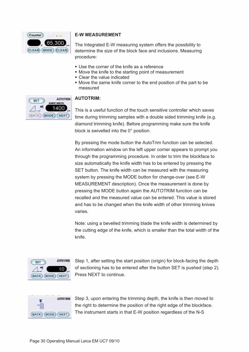
E-W MEASUREMENT
The Integrated E-W measuring system offers the possibility to determine the size of the block face and inclusions. Measuring procedure:
� Use the corner of the knife as a reference � Move the knife to the starting point of measurement � Clear the value indicated � Move the same knife corner to the end position of the part to be
measured
AUTOTRIM:
This is a useful function of the touch sensitive controller which saves time during trimming samples with a double sided trimming knife (e.g. diamond trimming knife). Before programming make sure the knife block is swivelled into the 0° position.
By pressing the mode button the AutoTrim function can be selected. An information window on the left upper corner appears to prompt you through the programming procedure. In order to trim the blockface to size automatically the knife width has to be entered by pressing the SET button. The knife width can be measured with the measuring system by pressing the MODE button for change-over (see E-W MEASUREMENT description). Once the measurement is done by pressing the MODE button again the AUTOTRIM function can be recalled and the measured value can be entered. This value is stored and has to be changed when the knife width of other trimming knives varies.
Note: using a bevelled trimming blade the knife width is determined by the cutting edge of the knife, which is smaller than the total width of the knife.
Step 1, after setting the start position (origin) for block-facing the depth of sectioning has to be entered after the button SET is pushed (step 2). Press NEXT to continue.
Step 3, upon entering the trimming depth, the knife is then moved to the right to determine the position of the right edge of the blockface. The instrument starts in that E-W position regardless of the N-S
Page 30 Operating Manual Leica EM UC7 09/10

position. N-S is determined by the origin position (step 1). Press NEXT to continue.
By using a 45° bevelled trimming knife blade it has to be taken into account that the position of the right edge of the specimen block will be shifted by approx. 1.25x of the trimming depth.
Step 4, key in the total depth of trimming after pushing the SET button. Press NEXT to continue.
Step 5, the size of the blockface is entered after pushing the SET button. During trimming the knife moves automatically to the left E-W position of the sample block (calculated by the width of the knife, right position of step 3 and specimen width which was entered). Press NEXT to continue.
By using a 45° bevelled trimming knife blade it has to be taken into account that the specimen width will be reduced by approx. 2.5x of the trimming depth, e.g. in order to receive a 500µm blockface-size with a total depth of trimming of 200µm the entered specimen width should be 1000µm.
For safety reasons after pressing START button the knife moves approx. 500μm backwards before moving E-W and starts sectioning at the position of the 1st step.
The progress of the cutting step is indicated on the status line. It might be that trimming the blockface needs to be interrupted and skipped. This can be done by pressing the green START/STOP button followed by YES in the “Blockface ready?“ box.
Page 31 Operating Manual Leica EM UC7 09/10
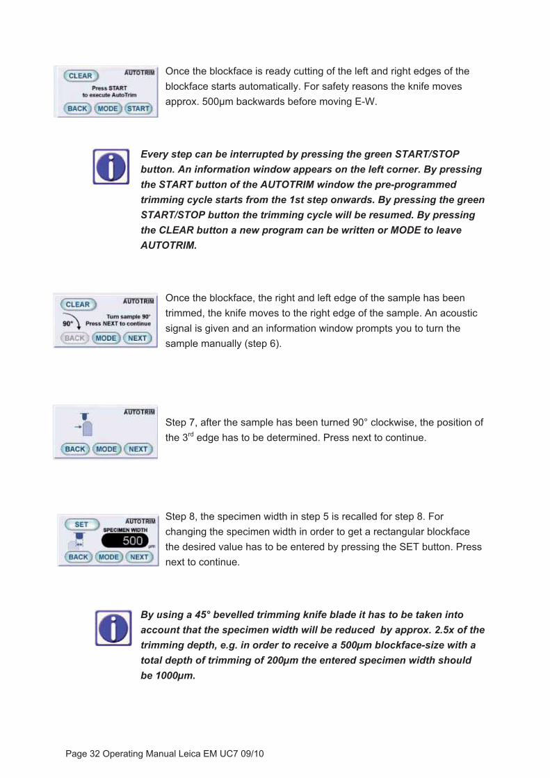
Once the blockface is ready cutting of the left and right edges of the blockface starts automatically. For safety reasons the knife moves approx. 500μm backwards before moving E-W.
Every step can be interrupted by pressing the green START/STOP button. An information window appears on the left corner. By pressing the START button of the AUTOTRIM window the pre-programmed trimming cycle starts from the 1st step onwards. By pressing the green START/STOP button the trimming cycle will be resumed. By pressing the CLEAR button a new program can be written or MODE to leave AUTOTRIM.
Once the blockface, the right and left edge of the sample has been trimmed, the knife moves to the right edge of the sample. An acoustic signal is given and an information window prompts you to turn the sample manually (step 6).
Step 7, after the sample has been turned 90° clockwise, the position of the 3rd edge has to be determined. Press next to continue.
Step 8, the specimen width in step 5 is recalled for step 8. For changing the specimen width in order to get a rectangular blockface the desired value has to be entered by pressing the SET button. Press next to continue.
By using a 45° bevelled trimming knife blade it has to be taken into account that the specimen width will be reduced by approx. 2.5x of the trimming depth, e.g. in order to receive a 500µm blockface-size with a total depth of trimming of 200µm the entered specimen width should be 1000µm.
Page 32 Operating Manual Leica EM UC7 09/10
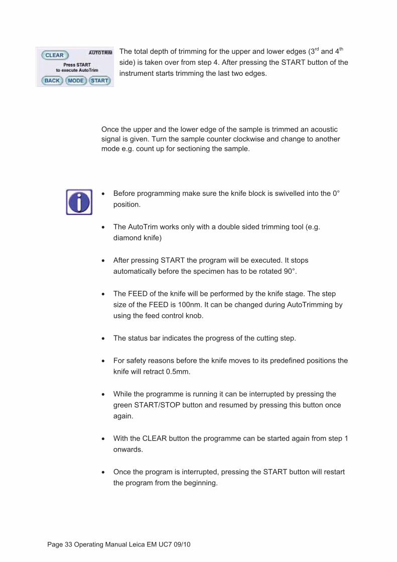
The total depth of trimming for the upper and lower edges (3rd and 4th
side) is taken over from step 4. After pressing the START button of the instrument starts trimming the last two edges.
Once the upper and the lower edge of the sample is trimmed an acoustic signal is given. Turn the sample counter clockwise and change to another mode e.g. count up for sectioning the sample.
� Before programming make sure the knife block is swivelled into the 0° position.
� The AutoTrim works only with a double sided trimming tool (e.g. diamond knife)
� After pressing START the program will be executed. It stops automatically before the specimen has to be rotated 90°.
� The FEED of the knife will be performed by the knife stage. The step size of the FEED is 100nm. It can be changed during AutoTrimming by using the feed control knob.
� The status bar indicates the progress of the cutting step.
� For safety reasons before the knife moves to its predefined positions the knife will retract 0.5mm.
� While the programme is running it can be interrupted by pressing the green START/STOP button and resumed by pressing this button once again.
� With the CLEAR button the programme can be started again from step 1 onwards.
� Once the program is interrupted, pressing the START button will restart the program from the beginning.
Page 33 Operating Manual Leica EM UC7 09/10
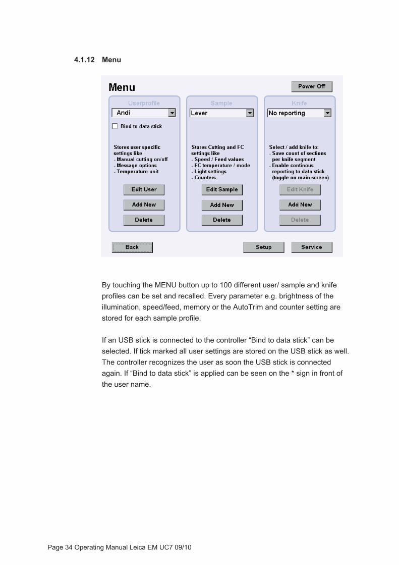
4.1.12 Menu
By touching the MENU button up to 100 different user/ sample and knife profiles can be set and recalled. Every parameter e.g. brightness of the illumination, speed/feed, memory or the AutoTrim and counter setting are stored for each sample profile.
If an USB stick is connected to the controller “Bind to data stick” can be selected. If tick marked all user settings are stored on the USB stick as well. The controller recognizes the user as soon the USB stick is connected again. If “Bind to data stick” is applied can be seen on the * sign in front of the user name.
Page 34 Operating Manual Leica EM UC7 09/10

4.1.12.1 Add and edit user profile
If a new user is added key in the name in the window which appears after “Add New” is pressed. Continue as mentioned below.
� Enable Manual Cutting - sectioning can be performed using the hand wheel.
� Bind Motor to EM Crion Pedals – the specimen arm motor is switched off or on as soon the foot switch is pressed.
� Enable Continuous Approach - by pressing the north step button of the control panel the knife moves towards the sample while this button is pressed.
� Show Cutting Animation - the segment of the cutting range, the indication of the cutting window and the selected return speed lights up on the control panel when the specimen arm is in that position.
� Show Info Messages - the instrument indicates information messages in the upper right corner
� Show Confirm Messages - for safety reasons, confirm messages will be displayed when the RESET and the FC Mount button is pressed.
� Play Sound on Button-Click – enables button click as soon the buttons are pressed.
� Standby – screensaver, after the selected time the light of the screen is switched off.
� Stage Feed Minimum - advance of the stage (instead of the specimen arm) will be performed when the selected FEED corresponds or exceeds that value.
Page 35 Operating Manual Leica EM UC7 09/10
� Beep Volume - increases or decreases the volume of the acoustic signals.
In conjunction with the EM FC7 temperature Unit °C or °F or °K can be selected to be displayed.
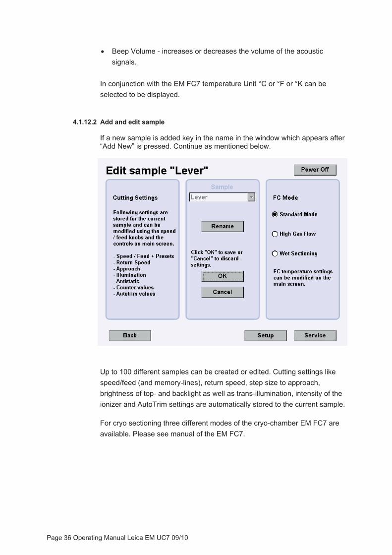
4.1.12.2 Add and edit sample
If a new sample is added key in the name in the window which appears after “Add New” is pressed. Continue as mentioned below.
Up to 100 different samples can be created or edited. Cutting settings like speed/feed (and memory-lines), return speed, step size to approach, brightness of top- and backlight as well as trans-illumination, intensity of the ionizer and AutoTrim settings are automatically stored to the current sample.
For cryo sectioning three different modes of the cryo-chamber EM FC7 are available. Please see manual of the EM FC7.
Page 36 Operating Manual Leica EM UC7 09/10
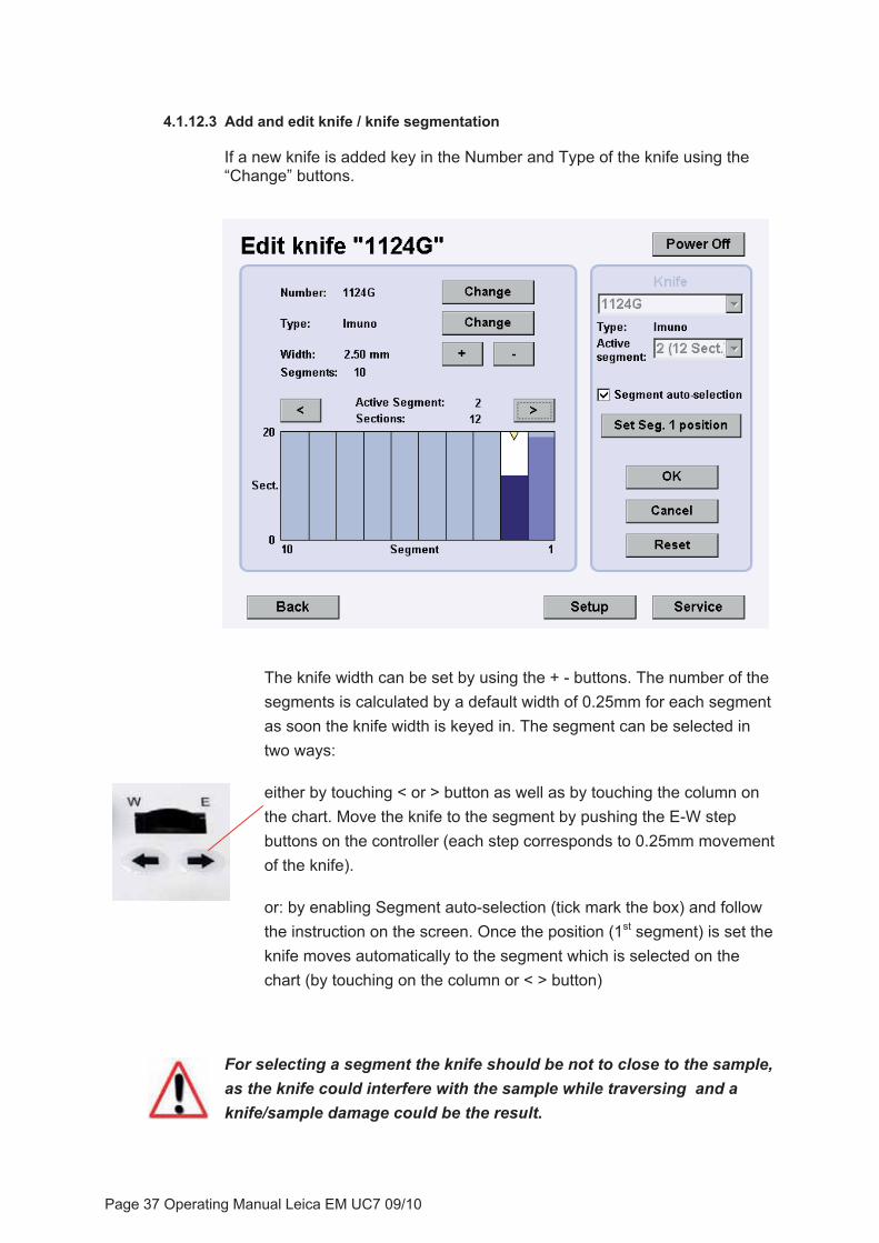
4.1.12.3 Add and edit knife / knife segmentation
If a new knife is added key in the Number and Type of the knife using the “Change” buttons.
The knife width can be set by using the + - buttons. The number of the segments is calculated by a default width of 0.25mm for each segment as soon the knife width is keyed in. The segment can be selected in two ways:
either by touching < or > button as well as by touching the column on the chart. Move the knife to the segment by pushing the E-W step buttons on the controller (each step corresponds to 0.25mm movement of the knife).
or: by enabling Segment auto-selection (tick mark the box) and follow the instruction on the screen. Once the position (1st segment) is set the knife moves automatically to the segment which is selected on the chart (by touching on the column or < > button)
For selecting a segment the knife should be not to close to the sample, as the knife could interfere with the sample while traversing and a knife/sample damage could be the result.
Page 37 Operating Manual Leica EM UC7 09/10
If the sample size is smaller than 0.25mm width of the segment the position within the segment can be changed by using the E-W coarse wheel. The actual position is indicated with the yellow triangle. The sections at the complete segment will be continuously counted.
The selected segment is displayed on the REPORT window on the main screen. The segment can be changed using the E-W movement without changing over to the menu.
After resharpening the knife the segments can be cleared by pressing the RESET button.
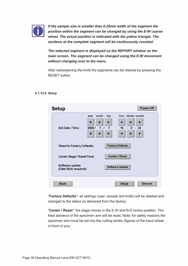
4.1.12.4 Setup
“Factory Defaults”: all settings (user, sample and knife) will be deleted and changed to the status as delivered from the factory.
“Center / Reset”: the stage moves in the E-W and N-S centre position. The feed advance of the specimen arm will be reset. Note: for safety reasons the specimen arm must be set into the cutting stroke (figures of the hand wheel in front of you)
Page 38 Operating Manual Leica EM UC7 09/10
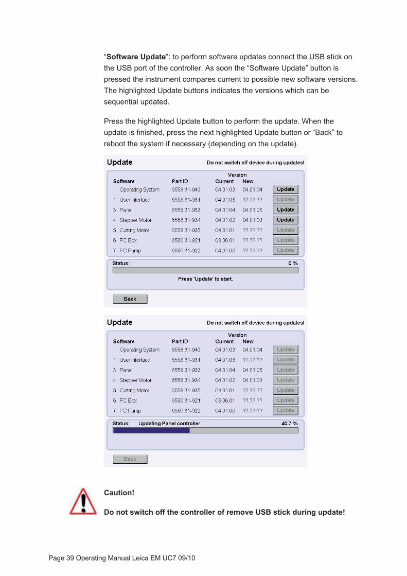
“Software Update”: to perform software updates connect the USB stick on the USB port of the controller. As soon the “Software Update” button is pressed the instrument compares current to possible new software versions. The highlighted Update buttons indicates the versions which can be sequential updated.
Press the highlighted Update button to perform the update. When the update is finished, press the next highlighted Update button or “Back” to reboot the system if necessary (depending on the update).
Caution!
Do not switch off the controller of remove USB stick during update!
Page 39 Operating Manual Leica EM UC7 09/10

4.1.13 Knife usage (report and upload data to USB stick)
For reporting the knife usage chose a knife from the menu window. Uploading user-, sample- and knife parameter to an USB stick will be enabled as well. If you select “No reporting” uploading these parameters is not possible and the report window on the main screen will not appear.
Select the knife segment on which thesectioning process will be performed.
As soon a knife is selected the report window appears on the main screen. The sections on the segment will be counted as long as this window is activated by pressing the Report button. Pressing the Report button again the window is fade to grey and the counter is inactive.
To upload user-, sample- and knife data connect the USB stick to the controller and press “UPLOAD”, a grid box window will appear.
Select the grid position on the box by touching the field e.g. A1. You may change the grid box number by pressing the “Change” button. Press “OK” to upload grid position to the log file. Press “Cancel” to upload parameter without uploading grid information.
Page 40 Operating Manual Leica EM UC7 09/10

4.1.14. Creating a protocol (log book)
Disconnect the USB stick from the UC7 controller and connect it to a computer which has an Excel program installed. Select the “UC7Reports” folder. “UC7Data” folder will be created if “Bind to data stick” was enabled (see 4.1.12) and can be left unconsidered.
Open the desired report by double-clicking the report file.
The report will be opened by using the Excel program. It might be necessary to adjust the size of the columns.
Page 41 Operating Manual Leica EM UC7 09/10
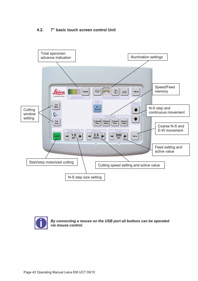
4.2. 7” basic touch screen control Unit
Coarse N-S and E-W movement
Start/stop motorized cutting Cutting speed setting and active value
Feed setting and active value
N-S step size setting
Cuttingwindowsetting
Total specimen advance indication
N-S step and continuous movement
Speed/Feedmemory
Illumination settings
By connecting a mouse on the USB port all buttons can be operated via mouse control.
Page 42 Operating Manual Leica EM UC7 09/10
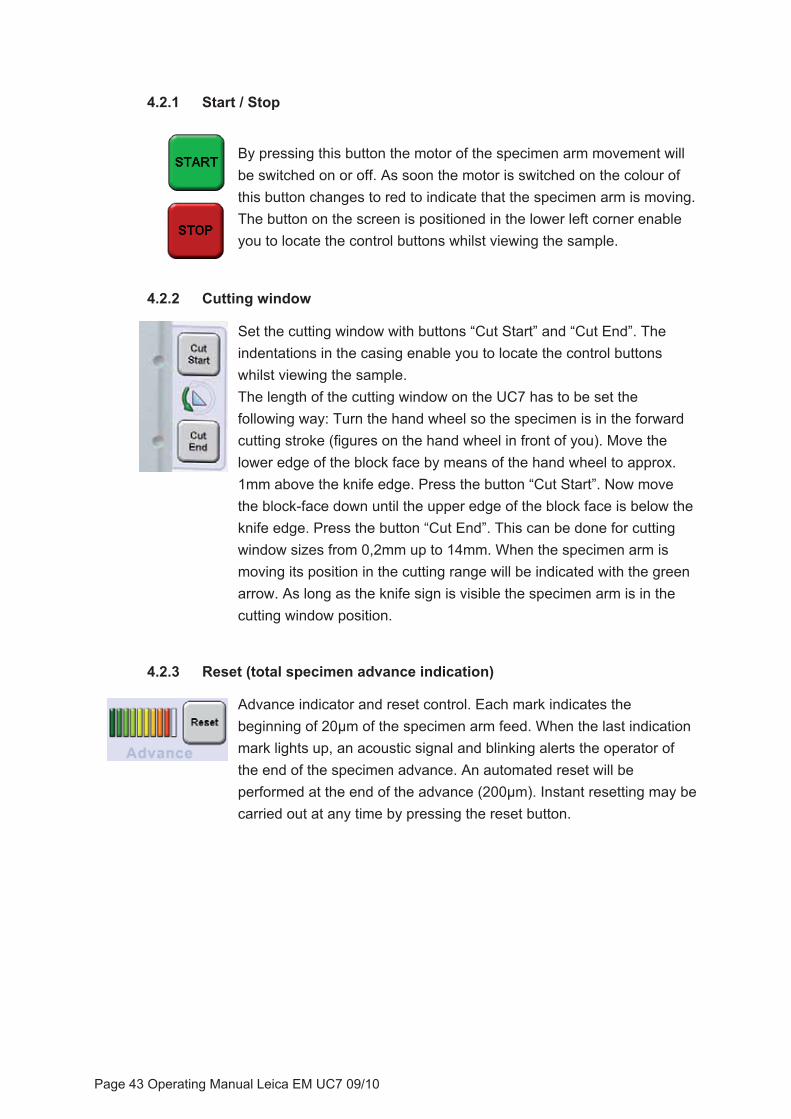
4.2.1 Start / Stop
By pressing this button the motor of the specimen arm movement will be switched on or off. As soon the motor is switched on the colour of this button changes to red to indicate that the specimen arm is moving. The button on the screen is positioned in the lower left corner enable you to locate the control buttons whilst viewing the sample.
4.2.2 Cutting window
Set the cutting window with buttons “Cut Start” and “Cut End”. The indentations in the casing enable you to locate the control buttons whilst viewing the sample. The length of the cutting window on the UC7 has to be set the following way: Turn the hand wheel so the specimen is in the forward cutting stroke (figures on the hand wheel in front of you). Move the lower edge of the block face by means of the hand wheel to approx. 1mm above the knife edge. Press the button “Cut Start”. Now move the block-face down until the upper edge of the block face is below the knife edge. Press the button “Cut End”. This can be done for cutting window sizes from 0,2mm up to 14mm. When the specimen arm is moving its position in the cutting range will be indicated with the green arrow. As long as the knife sign is visible the specimen arm is in the cutting window position.
4.2.3 Reset (total specimen advance indication)
Advance indicator and reset control. Each mark indicates the beginning of 20μm of the specimen arm feed. When the last indication mark lights up, an acoustic signal and blinking alerts the operator of the end of the specimen advance. An automated reset will be performed at the end of the advance (200μm). Instant resetting may be carried out at any time by pressing the reset button.
Page 43 Operating Manual Leica EM UC7 09/10

4.2.4 Illumination
Top-light
Spot-light
Back-light
Trans-illumination
The UC7 is equipped with four different types of LED illumination.
Top-light is used for observation of the cutting process and judgment of the section thickness.
Spot-light is used for knife inspection and site specific trimming.
Trans-illumination is used for locating and identifying interesting structures within the specimen block when trimming with the MESACUT or with the trimming block. Mounting the trans-illumination see point 5.3
Back-light is used for alignment of the diamond and glass knives with the sample and for knife inspection for contamination and flaws (nicks) before sectioning.
The brightness can be set in the menu (see point 4.2.8).
4.2.5 Speed / Feed
Set Cutting speed and feed:
Use the + or - button to adjust speed of the specimen between 0.05 and 100mm/sec and feed between 1nm and 15μm. Actual values are indicated in between the + and – buttons.
The specimen arm performs the advance of the specimen up to 2500nm feed setting. Above 2500nm the feed is performed by the stage.
Page 44 Operating Manual Leica EM UC7 09/10
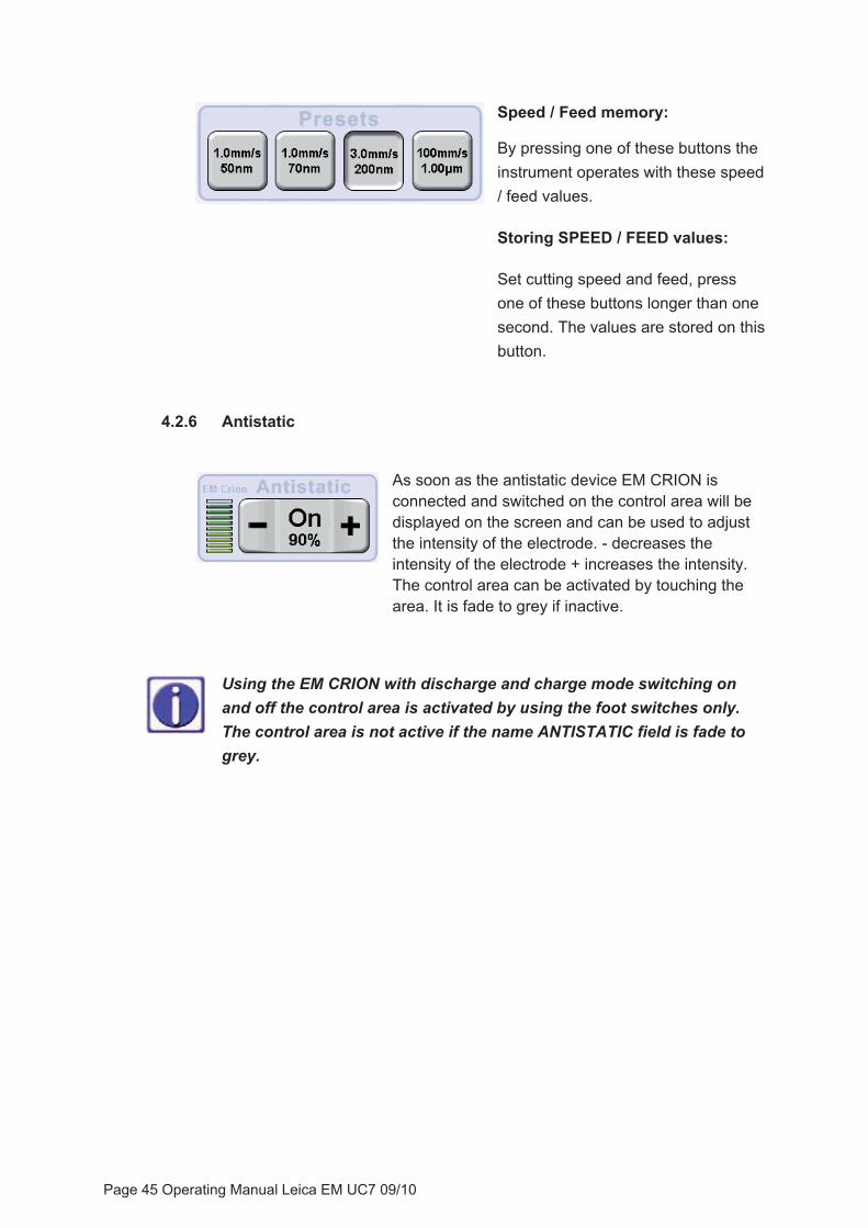
Speed / Feed memory:
By pressing one of these buttons the instrument operates with these speed / feed values.
Storing SPEED / FEED values:
Set cutting speed and feed, press one of these buttons longer than one second. The values are stored on this button.
4.2.6 Antistatic
As soon as the antistatic device EM CRION is connected and switched on the control area will be displayed on the screen and can be used to adjust the intensity of the electrode. - decreases the intensity of the electrode + increases the intensity. The control area can be activated by touching the area. It is fade to grey if inactive.
Using the EM CRION with discharge and charge mode switching on and off the control area is activated by using the foot switches only. The control area is not active if the name ANTISTATIC field is fade to grey.
Page 45 Operating Manual Leica EM UC7 09/10

4.2.7 Knife approach
By pushing the “Move” button two slide controls for N-S and E-W movement of the knife stage appear. Some buttons changes the colour of the lettering to white which indicates that they are disabled.
origin
To control the N-S movement touch the slide control and move the finger to north or south. The lager the distance from the origin the faster is the movement of the stage. N-S step advance can be performed by pushing the slide control on the north side above of origin or on the south side below of origin. The step size can be set from 100nm to 15μm. E-W step advance can be performed by pushing the slide control on the west side left of origin or on the east side right of origin. The step size of the E-W step control is 0.25mm and can’t be changed.
After leaving the “move“ screen a step advance can be performed on the main screen as well. Step size can be set using +/- buttons.
If continuous approach is enabled (menu) the knife stage will move towards the specimen while Step is pressed. Continuous return of the knife stage can be achieved while Step to the north is pressed.
Page 46 Operating Manual Leica EM UC7 09/10
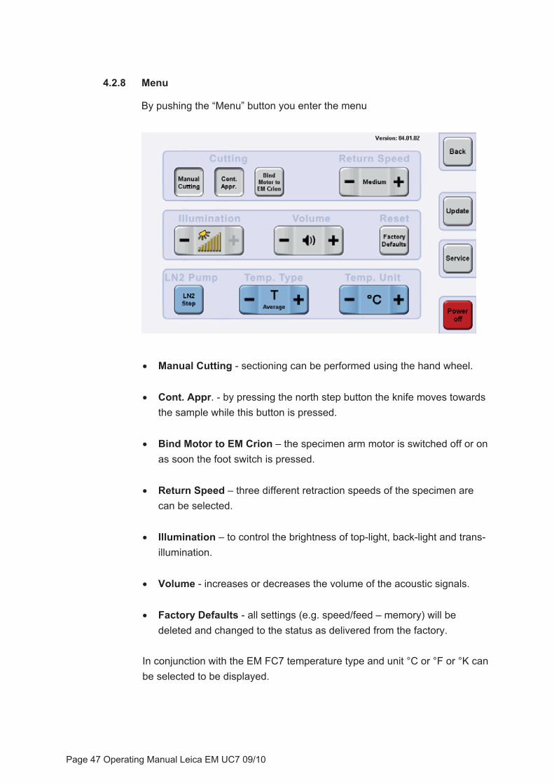
4.2.8 Menu
By pushing the “Menu” button you enter the menu
� Manual Cutting - sectioning can be performed using the hand wheel.
� Cont. Appr. - by pressing the north step button the knife moves towards the sample while this button is pressed.
� Bind Motor to EM Crion – the specimen arm motor is switched off or on as soon the foot switch is pressed.
� Return Speed – three different retraction speeds of the specimen are can be selected.
� Illumination – to control the brightness of top-light, back-light and trans-illumination.
� Volume - increases or decreases the volume of the acoustic signals.
� Factory Defaults - all settings (e.g. speed/feed – memory) will be deleted and changed to the status as delivered from the factory.
In conjunction with the EM FC7 temperature type and unit °C or °F or °K can be selected to be displayed.
Page 47 Operating Manual Leica EM UC7 09/10

Software Update - to perform software updates connect the USB stick on the USB port of the controller. As soon the “Update” button is pressed the instrument compares current to possible new software versions. Available updates are marked with a red cross. To update press this (these) button(s) followed by the “Start Update” button.
Caution!
Do not switch off the controller of remove USB stick during update!
Page 48 Operating Manual Leica EM UC7 09/10
5. Description of the Equipment
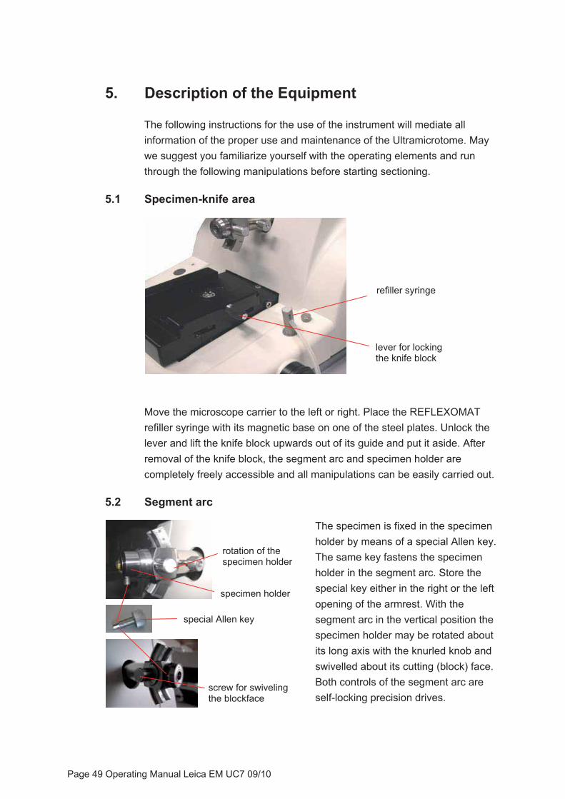
The following instructions for the use of the instrument will mediate all information of the proper use and maintenance of the Ultramicrotome. May we suggest you familiarize yourself with the operating elements and run through the following manipulations before starting sectioning.
5.1 Specimen-knife area
refiller syringe
lever for locking the knife block
Move the microscope carrier to the left or right. Place the REFLEXOMAT refiller syringe with its magnetic base on one of the steel plates. Unlock the lever and lift the knife block upwards out of its guide and put it aside. After removal of the knife block, the segment arc and specimen holder are completely freely accessible and all manipulations can be easily carried out.
5.2 Segment arc
The specimen is fixed in the specimen holder by means of a special Allen key. The same key fastens the specimen holder in the segment arc. Store the special key either in the right or the left opening of the armrest. With the segment arc in the vertical position the specimen holder may be rotated about its long axis with the knurled knob and swivelled about its cutting (block) face. Both controls of the segment arc are self-locking precision drives.
special Allen key
specimen holder
rotation of the specimen holder
screw for swiveling the blockface
Page 49 Operating Manual Leica EM UC7 09/10

mount shaft on this position
unscrew the hex screw
shaft of the segment arc
For longitudinal or radial sections the shaft of the segment arc can also be placed at the end position of the segment arc. This is done by unscrewing it from the centre position and tightening it again at the end position of the segment arc.
5.3 Specimen transillumination
The transillumination is connected with the connecting cable and its plug to the outlet on the right side of the support carrier. The other side with the LED is inserted into the swivelling part of the segment arc. Swivel the arc into the upper position and insert the LED mounting, clamping screw (plastic head) facing you.
Page 50 Operating Manual Leica EM UC7 09/10
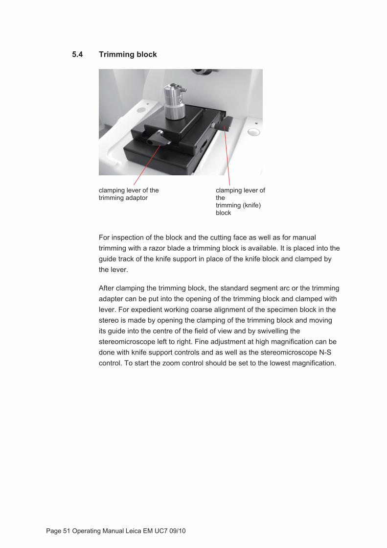
5.4 Trimming block
clamping lever of thetrimming (knife) block
clamping lever of the trimming adaptor
For inspection of the block and the cutting face as well as for manual trimming with a razor blade a trimming block is available. It is placed into the guide track of the knife support in place of the knife block and clamped by the lever.
After clamping the trimming block, the standard segment arc or the trimming adapter can be put into the opening of the trimming block and clamped with lever. For expedient working coarse alignment of the specimen block in the stereo is made by opening the clamping of the trimming block and moving its guide into the centre of the field of view and by swivelling the stereomicroscope left to right. Fine adjustment at high magnification can be done with knife support controls and as well as the stereomicroscope N-S control. To start the zoom control should be set to the lowest magnification.
Page 51 Operating Manual Leica EM UC7 09/10
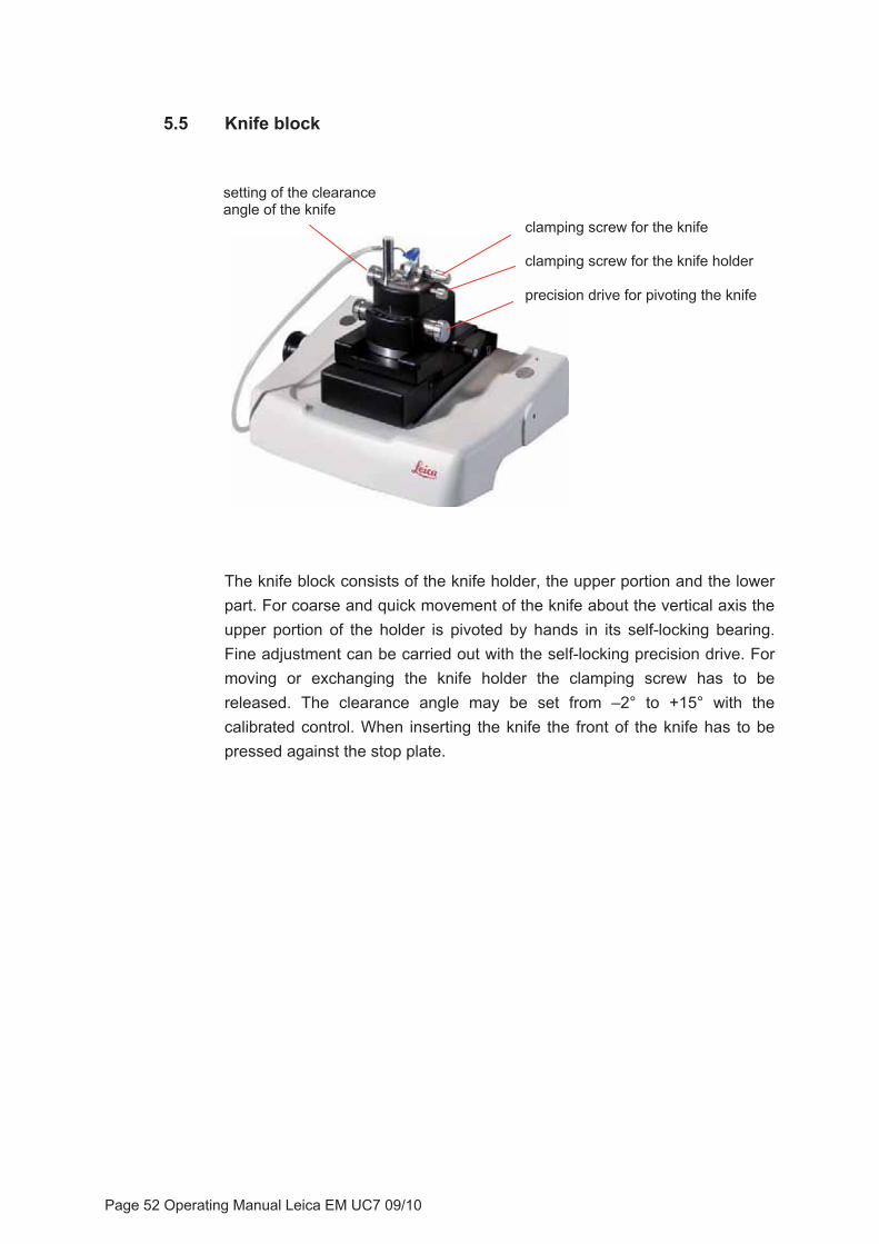
5.5 Knife block
precision drive for pivoting the knife
clamping screw for the knife holder
setting of the clearance angle of the knife
clamping screw for the knife
The knife block consists of the knife holder, the upper portion and the lower part. For coarse and quick movement of the knife about the vertical axis the upper portion of the holder is pivoted by hands in its self-locking bearing. Fine adjustment can be carried out with the self-locking precision drive. For moving or exchanging the knife holder the clamping screw has to be released. The clearance angle may be set from –2° to +15° with the calibrated control. When inserting the knife the front of the knife has to be pressed against the stop plate.
Page 52 Operating Manual Leica EM UC7 09/10
5.6 Drive system
To switch on the motor drive, the green button START/STOP has to be pressed. The motor runs and the handwheel rotates.
Turning the SPEED knob varies the cutting speed between 0,05 and 100 mm/s. When choosing a very slow speed e.g. 0,05 mm/s it will be easy to see that the specimen is moving very slowly in a certain part of its downward movement (cutting window) and thereafter much faster.
The cycling will be indicated by the highlighted segments on the control unit (if Show Cutting Animation is enabled see 4.1.12). During the return stroke the specimen is automatically retracted by approx. 0,2 mm so that the cutting edge of the knife is not touched by the specimen in the return stroke.
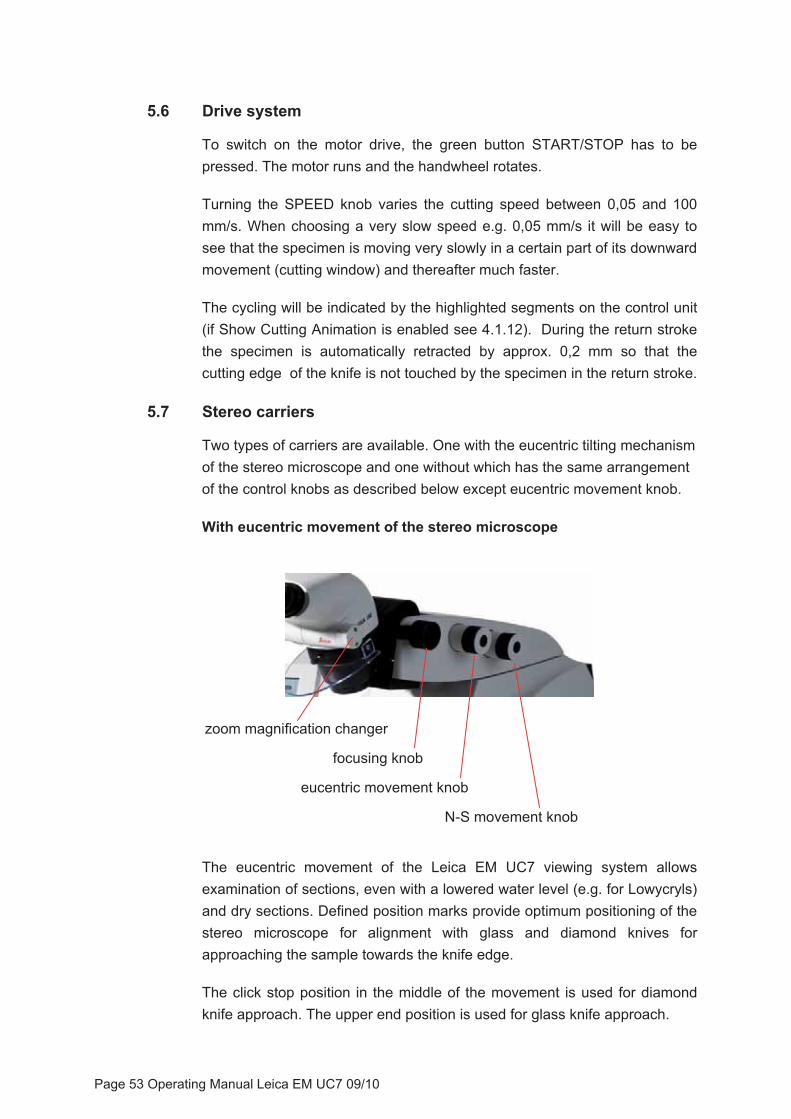
5.7 Stereo carriers
Two types of carriers are available. One with the eucentric tilting mechanism of the stereo microscope and one without which has the same arrangement of the control knobs as described below except eucentric movement knob.
With eucentric movement of the stereo microscope
zoom magnification changer
focusing knob
eucentric movement knob
N-S movement knob
The eucentric movement of the Leica EM UC7 viewing system allows examination of sections, even with a lowered water level (e.g. for Lowycryls) and dry sections. Defined position marks provide optimum positioning of the stereo microscope for alignment with glass and diamond knives for approaching the sample towards the knife edge.
The click stop position in the middle of the movement is used for diamond knife approach. The upper end position is used for glass knife approach.
Page 53 Operating Manual Leica EM UC7 09/10
Example using the eucentric movement at lowered water level:
without eucentric movement with eucentric movement
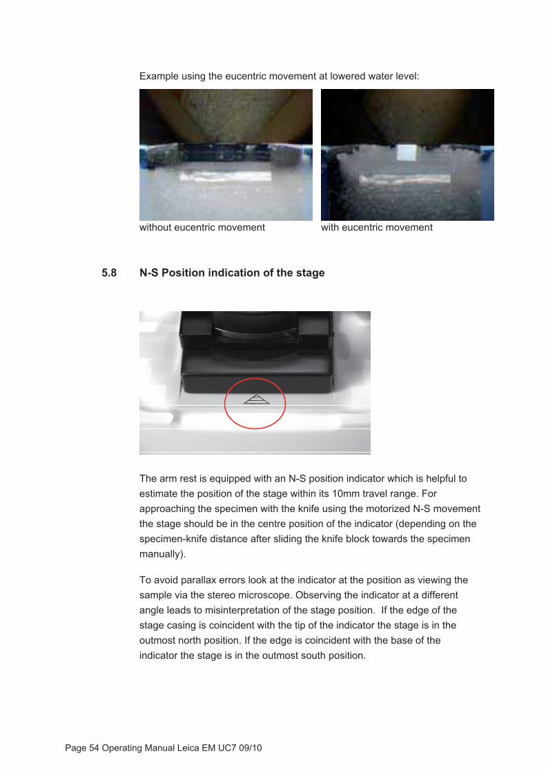
5.8 N-S Position indication of the stage
The arm rest is equipped with an N-S position indicator which is helpful to estimate the position of the stage within its 10mm travel range. For approaching the specimen with the knife using the motorized N-S movement the stage should be in the centre position of the indicator (depending on the specimen-knife distance after sliding the knife block towards the specimen manually).
To avoid parallax errors look at the indicator at the position as viewing the sample via the stereo microscope. Observing the indicator at a different angle leads to misinterpretation of the stage position. If the edge of the stage casing is coincident with the tip of the indicator the stage is in the outmost north position. If the edge is coincident with the base of the indicator the stage is in the outmost south position.
Page 54 Operating Manual Leica EM UC7 09/10

6. Technical specifications
Magnification M80: 9.6x-77x S6E: 10x -64x
Ergo-Wedge 5°-25°Eucentric movement of the stereo carrier +5°/-8°Built in control of antistatic device and FC7 yes Top-light LED brightness controllable Back-light LED brightness controllable Transillumination LED brightness controllable Spot-light LEDCutting transmission vibration decoupled gravity stroke Specimen advance 200μmReserve warning 20μmSegment arc 360° rotatable specimen eucentric movement +/-22°Knife block 360° rotatable self locking yes graduation +/-30° graduation clearance angle adjustment -2° to 15° with 1° scaleKnife holder for 6-12mm knives Coarse knife-movements N-S: 10 mm stepping motor E-W. 25mm stepping motor Cutting window 0.2 -14 mm adjustable Cutting speed 0.05 -100 mm/s wheel controlledSection thickness 0-15000nm wheel controlled
FEED/SPEED storage (combined) 5 advanced controller / 4 basic controller
Return speeds 10, 30, 50mm/sStep control 0.1 -15 μm steps
Page 55 Operating Manual Leica EM UC7 09/10


EC Declaration
Leica Microsysteme GmbH Tel. +43 1 48899 Hernalser Hauptstrasse 219 Fax +43 1 48899-350 A-1170 Wien www.leica-microsystems.com
EC Declaration of Conformity EG Konformitäts-Erklärung Déclaration CE de Conformité
We/Wir/Nous Leica Mikrosysteme GmbH Hernalser Hauptstrasse 219 A-1170 Wien, Austria
declare in exclusive responsibility that the product erklären in alleiniger Verantwortung, dass das Produkt déclarons sous notre seule responsabilité que le produit
Model LEICA EM UC7
Modell LEICA EM UC7
modèle LEICA EM UC7
Type/Typenbezeichnung/type UC7/655850 UC7/655851
to which this declaration relates is in conformity with the following standards: auf das sich diese Erklärung bezieht, mit den folgenden Normen übereinstimmt: auquel se réfère cette déclaration est conforme aux normes :
EN 61010-1
EN 61326-1
following the provisions of directive gemäss den Bestimmungen der Richtlinie conformément aux dispositions de directive
2004/108/EC (Electromagnetic compatibility) (Elektromagnetische Verträglichkeit)
2006/95/EC (Low Voltage Equipment) (Niederspannungsrichtlinie)
2006/42/EC (Machinery) (Maschinen)
Wien, 25. June 2009 Dr. Reinhard Lihl Entwicklungsleiter R & D Manager Chef du service développement

Copy
right
© L
eica
Mik
rosy
stem
e G
mbH
, Her
nals
er H
aupt
stra
sse
219,
117
0 Vi
enna
, Aus
tria
· Tel
. +43
1 4
8899
, Fax
+43
1 4
8899
350
LE
ICA
and
the
Leic
a lo
gos
are
regi
ster
ed tr
adem
arks
of L
eic
IR G
mbH�
Ord
er n
os. o
f the
edi
tions
in: O
pera
ting
Man
ual L
eica
EM
UC7
, Ver
sion
162
1603
2 09
/201
0
Prin
ted
on c
hlor
ine-
free
ble
ache
d pa
per.
�
��������������������������