ucr511 digital hybrid wireless receiver (europe) operating
TRANSCRIPT

Featuring Digital Hybrid Wireless™ Technology(US Patent Pending)
0560
UHF RECEIVER(Includes IFB Compatibility Mode)
UCR511
OPERATING INSTRUCTIONS
Rio Rancho, NM, USAwww.lectrosonics.com

2
UCR511

3
UHF Wireless Digital HybridTM Receiver
Rio Rancho, NM – USA
TABLE OF CONTENTSGENERAL TECHNICAL DESCRIPTION ...................................................................................................... 5
COMPATIBILITY MODES ............................................................................................................................................... 5DIVERSITY RECEPTION .............................................................................................................................................. 5RF FREQUENCY TRACKING FRONT-END AND MIXER ............................................................................................ 5MICROCONTROLLER, PLL AND VCO CIRCUITS ....................................................................................................... 5IF AMPLIFIERS AND SAW FILTERS ............................................................................................................................. 5DIGITAL PULSE COUNTING DETECTOR .................................................................................................................... 6DSP-BASED PILOT TONE ............................................................................................................................................. 6SMART SQUELCH™ ..................................................................................................................................................... 6SMART NOISE REDUCTION (SmartNR™) .................................................................................................................. 6RF-CONTROLLED DIGITAL NOISE FILTER ................................................................................................................. 7OUTPUT LEVEL ADJUST ............................................................................................................................................. 7TEST TONE .................................................................................................................................................................... 7BATTERIES .................................................................................................................................................................... 7POWER SUPPLY ........................................................................................................................................................... 7LCD DISPLAY ................................................................................................................................................................. 7POWER UP SEQUENCE ............................................................................................................................................... 7POWER OFF .................................................................................................................................................................. 7
FRONT PANEL CONTROLS AND FUNCTIONS ......................................................................................... 8SEL Up/Down ................................................................................................................................................................. 8MENU ............................................................................................................................................................................. 8
REAR PANEL FEATURES ............................................................................................................................ 8XLR AUDIO OUTPUT JACK .......................................................................................................................................... 8POWER ON/OFF ........................................................................................................................................................... 8LCD ................................................................................................................................................................................. 8POWER INPUT JACK .................................................................................................................................................... 8
MAIN WINDOW (LCD) ................................................................................................................................... 9PILOT TONE INDICTOR ........................................................................................................................................... 9ANTENNA PHASE INDICATOR ................................................................................................................................ 9RF LEVEL .................................................................................................................................................................. 9AUDIO LEVELS ......................................................................................................................................................... 9BATTERY LEVELS .................................................................................................................................................... 9
FREQUENCY WINDOW .............................................................................................................................................. 10MENU SELECTIONS FROM MAIN WINDOW ............................................................................................ 10
BATTERY LEVEL WINDOW ......................................................................................................................................... 10SETUP WINDOW ......................................................................................................................................................... 10
LEVEL ...................................................................................................................................................................... 11TONE ....................................................................................................................................................................... 11TXBAT ...................................................................................................................................................................... 11PHASE ..................................................................................................................................................................... 11SmtNR ..................................................................................................................................................................... 11TUNING ................................................................................................................................................................... 11
User Programmable Frequency Group Behavior ................................................................................................. 12Adding/Deleting User Programmable Frequency Group Entries .......................................................................... 12
COMPAT .................................................................................................................................................................. 12FREQUENCY SCAN MODE ........................................................................................................................ 13ANTENNA USE AND PLACEMENT ........................................................................................................... 14INSTALLATION AND OPERATING INSTRUCTIONS ............................................................................... 15
FINDING CLEAR FREQUENCIES .............................................................................................................................. 15LOCKING AND UNLOCKING THE UCR511 FRONT PANEL CONTROLS ................................................................ 16
TO REPLACE THE BATTERIES ................................................................................................................. 17Frequency Coordination ............................................................................................................................ 18
Compatible Frequency Chart ........................................................................................................................................ 18Rule No. 1 ................................................................................................................................................................ 18
DIGITAL HYBRID WIRELESS™
The Lectrosonics Digital Hybrid Wireless™ uses innova-tive technology to combine the new advantages of digitalaudio with the classic advantages of analog RF trans-mission, thus delivering the superior sound quality of adigital system and the excellent range of an analogsystem. A proprietary algorithm encodes the digitalaudio information into an analog format which can betransmitted in a robust manner over an analog FMwireless link. The receiver employs the latest filters, RFamplifiers, mixers and detector to capture the encodedsignal and a DSP recovers the original digital audio.
This digital/analog hybrid technique has some verybeneficial properties. Because the information beingtransmitted is digitally encoded, immunity to noise ismuch higher than a compandor can offer. Because theencoded audio is sent in analog format, spectral andpower efficiency and operating range are not compro-mised. Under weak RF conditions, the received signaldegrades gracefully, like an analog system, delivering asmuch usable audio as possible at maximum range.Because the audio is not companded, no compandorartifacts are present at any audio or RF signal level. Thisgreatly reduces the pumping and breathing problemscommonly found in wireless systems with compandors.
(US Patent Pending)

4
UCR511
Rule No. 2 ................................................................................................................................................................ 18Rule No. 3 ................................................................................................................................................................ 20
Using the Scan Function .............................................................................................................................................. 20Call Lectrosonics .......................................................................................................................................................... 20
UCR511 REPLACEMENT PARTS AND ACCESSORIES ......................................................................... 21TROUBLESHOOTING ................................................................................................................................. 22
INITIAL POWER ON .................................................................................................................................................... 22PILOT TONE SQUELCH .............................................................................................................................................. 22ANTENNAS AND RF SIGNAL STRENGTH ................................................................................................................ 22AUDIO SIGNAL QUALITY ............................................................................................................................................ 23
SPECIFICATIONS AND FEATURES .......................................................................................................... 24SERVICE AND REPAIR ............................................................................................................................... 25LIMITED ONE YEAR WARRANTY .............................................................................................................. 28

5
UHF Wireless Digital HybridTM Receiver
Rio Rancho, NM – USA
The UCR511 is a portable, high performance, triple-conversion, frequency synthesized, UHF receiver fullycompatible with all Lectrosonics 500 series transmitters(and some other transmitter types – see CompatibilityModes for details.) The RF performance is extremelystable over a very wide temperature range, making theUCR511 perfectly suited to the rough environmentalconditions found in the field. The proprietary audioprocessing includes a digital signal processor for verylow distortion and a superior signal to noise ratio.
The UCR511 features a menu-driven LCD graphicdisplay and three control buttons to conveniently viewand alter user settings. The main window, for example,displays the pilot tone indicator, antenna diversity phase,RF level, audio level, receiver battery status and trans-mitter battery status. It is also possible to bypass thepilot tone/squelch from the main display window. Otherdisplay windows show operating frequency, audio outputlevel, battery voltage and test tone status. The fre-quency scan mode provides a spectrum analyzer for agraphical means of observing all signals “on the air”within the frequency range of the receiver in order to findoperating frequencies that are free of interference.
COMPATIBILITY MODESThe UCR511 receiver was designed to operate withLectrosonics 500 Series transmitters and will yield thebest performance when doing so. However, due to theflexibility of digital signal processing, the UCR511 is alsoable to operate with Lectrosonics 300 Series, Lectroson-ics 100 Series, and certain non-Lectrosonics transmittersin special compatibility modes.
DIVERSITY RECEPTIONThe UCR511 technology with SMART Diversity™ mini-mizes dropouts in situations where multi-path reflectionscan cause serious problems. The phase diversitynetwork and PIN diode RF switches are controlled by themicroprocessor using a sophisticated algorithm to useboth antennas simultaneously. This design keeps thereceiver compact enough for camera mounting or
shoulder bag applications, yet provides effective diversityreception.
RF FREQUENCY TRACKING FRONT-ENDAND MIXERThe receiver is frequency agile and can be set to operateon any one of 256 frequencies within its tuning range. Tosignificantly reduce unwanted interference and inter-modulation problems, the UCR511 has a frequencyselective front-end section that tracks and tunes to thedesired signal frequency and rejects or “tunes out”unwanted interfering signals. The design consists of fourvaractor tuned ceramic transmission line resonatorscontrolled by the microprocessor to provide excellentselectivity. The low noise high current RF amplifier wasdesigned with feedback regulation for stability andprecise gain in order to handle stronger RF signalswithout output overload. The first mixer is of new GaAstechnology that has a very high third order interceptpoint. This produces a robust front-end that is as selec-tive as fixed single frequency designs and is suitable foruse in close proximity to other receivers and transmitterscommonly used in field production “bag” systems.
MICROCONTROLLER, PLL AND VCOCIRCUITSThe 8-bit microprocessor is truly the “heart” of theUCR511 receiver. It monitors user command inputs fromthe front panel control buttons and numerous otherinternal signals such as RF level, audio levels, pilot tonelevels and external/internal power voltages. Outputsfrom the microcontroller drive the LCD display andbacklight, control the squelch and audio output attenua-tor, and operate the front-end tuning, the PLL/VCOcircuits and the antenna phase switch. The UCR511design and the advanced technology of the microproces-sor control arguably set a new standard in wirelessmicrophone development.
IF AMPLIFIERS AND SAW FILTERSThe first IF low noise amplifier is controlled with feed-back regulation and drives the first of two quartz SAW
2 (HI)
1 (COMMON)
3 (LO)
50
50
5K
5K
uP
LCDDisplayPanel
PILOT TONEDETECT
FILTER FILTER
uP uP
DIGITAL SIGNALPROCESSOR
Attenuation
CERAMICFILTER
2ND MIXER
10.7 MHZ
SAWFILTER
244 MHzIF AMP
A-DCONVERTER
D-ACONVERTER
AMP
2ndVCO
XLROUT
HI-LEVELMIXER
RF MODULE
3RD MIXERAND
IF AMP
50KHzLP FILTER
XTALCONTROLLED
3rdOSCILLATOR
SAWFILTER
244 MHzIF AMP
COUNTINGDETECTOR
AUDIOAMP
UCR511BLOCK DIAGRAM
ANTENNACOMBINING
FILTER
E PROM2
1stVCO
Smart Diversity
FILTER
PLLSYNTHESIZER
LCFilter
OutputLevelAdjust
DigitalAttenuator
GENERAL TECHNICAL DESCRIPTION

6
UCR511
(Surface Acoustical Wave) filters. The 244 MHz SAWfilters combine sharp tuning, constant group delay, widebandwidth and excellent temperature stability, far supe-rior to conventional LC filters. The 244 MHz first IFsignal is converted down to 10.7 MHz, filtered throughtwo ceramic filters for sharp selectivity, then converted to300 kHz.
DIGITAL PULSE COUNTING DETECTORThe UCR511 receiver uses an elegantly simple, yethighly effective digital pulse detector to demodulate theFM signal, rather than a conventional quadrature detec-tor. This unusual design eliminates thermal drift, im-proves AM rejection, and provides very low audiodistortion.
DSP-BASED PILOT TONENote
The above description applies only in 500 Series mode. In 300Series mode, only one pilot tone frequency is used on all channels,emulating the original crystal-based system. In other compatibility
modes, no pilot tone is used.
The 500 Series system design uses a DSP generatedultrasonic pilot tone to control the receiver audio muting(squelch). Brief delays (preset into the UCR511 cir-cuitry) eliminate thumps, pops or other transients thatcan occur when thewhen the associated 500 Seriestransmitter is turned on or off. The pilot tone frequencyis different for each of the 256 frequencies in the tuningrange of a system (frequency block.) This eliminatessquelch problems in multichannel systems where a pilottone signal can appear in the wrong receiver via inter-modulation products. The DSP generated pilot tone alsoeliminates the need for fragile crystals, allowing thereceiver to survive shocks and mishandling much betterthan older analog-based pilot tone systems.
SMART SQUELCH™
The UCR511 employs a sophisticated squelching systemin an attempt to deliver the cleanest possible audioduring marginal conditions of reception. Any squelchingsystem faces inevitable trade-offs: squelch too much andvaluable audio information may be lost, squelch too littleand excessive noise may be heard; respond too rapidlyand the audio sounds “choppy,” respond too sluggishlyand syllables or entire words can be cut off.
The UCR511 combines several techniques to achieve anoptimal balance, removing distracting noise, without thesquelching action itself becoming a distraction. One ofthese techniques involves waiting for a word or syllableto complete before squelching. Another incorporatesrecent squelching history and recent signal strength,adjusting squelching behavior dynamically for the mostserviceable result under variable conditions. Using these
and other techniques, the UCR511 can deliver accept-able audio quality from otherwise unusable signals.
In the Pilot Tone Bypass mode, the squelch system isdisabled. Received audio remains unmuted at all timeswith this setting. (See Front Panel Controls and Func-tions.)
SMART NOISE REDUCTION (SmartNR™)Note
The SmartNR setting is user selectable only in 500 Series mode. Inother modes, noise reduction is applied in such a way as to emulatethe original analog system as accurately as possible and is not user
adjustable.
The UCR511 has been meticulously designed using thebest available low noise components and techniques.Nonetheless, the wide dynamic range of digital hybridtechnology, combined with flat response to 20 kHz,makes it possible to hear the -120 dBV noise floor in themic preamp, or the (usually) greater noise from themicrophone itself. (To put this in perspective, the noisegenerated by the recommended 4 k Ohm bias resistor ofmany electret lavaliere mics is –119 dBV and the noiselevel of the microphone’s electronics is much higher.) Inorder to reduce this noise and thus increase the effectivedynamic range of the system, the UCR511 is equippedwith a Smart Noise Reduction algorithm, which removeshiss without sacrificing high frequency response.
The Smart Noise Reduction algorithm works by attenuat-ing only those portions of the audio signal that fit astatistical profile for randomness or “electronic hiss”.Because it isn’t simply the same sophisticated variablelow pass filter as in Lectrosonics’s 300 Series designs,much greater transparency is thus obtained. Desiredhigh frequency signals having some coherence such asspeech sibilance and tones are not affected.
The Smart Noise Reduction algorithm has three modes,selectable from a user setup screen - OFF/NORMAL/FULL.
OFF, no noise reduction is performed andcomplete transparency is preserved. All signalspresented to the transmitter’s analog front end,including any faint microphone hiss, will befaithfully reproduced at the receiver.
NORMAL, the factory default setting, enoughnoise reduction is applied to remove most of thehiss from the mic preamp and some of the hissfrom lavaliere microphones. The noise reductionbenefit is dramatic in this position, yet the degreeof transparency maintained is exceptional.
FULL, enough noise reduction is applied toremove most of the hiss from nearly any signalsource of reasonable quality, assuming levels areset properly at the transmitter. This additionalnoise reduction comes at the cost of sometransparency for low-level room noise, yet the
7
UHF Wireless Digital HybridTM Receiver
Rio Rancho, NM – USA
algorithm remains undetectable under mostcircumstances.
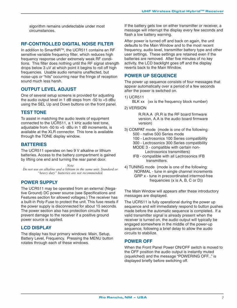
RF-CONTROLLED DIGITAL NOISE FILTERIn addition to SmartNRTM, the UCR511 contains an RFsensitive variable frequency filter, which reduces highfrequency response under extremely weak RF condi-tions. This filter does nothing until the RF signal strengthdrops below 3 uV at which point it begins to roll off highfrequencies. Usable audio remains unaffected, butnoise-ups or “hits” occurring near the fringe of receptionsound much less harsh.
OUTPUT LEVEL ADJUSTOne of several setup screens is provided for adjustingthe audio output level in 1 dB steps from -50 to +5 dBuusing the SEL Up and Down buttons on the front panel.
TEST TONETo assist in matching the audio levels of equipmentconnected to the UCR511, a 1 kHz audio test tone,adjustable from -50 to +5 dBu in 1 dB increments, isavailable at the XLR connector. This tone is availablethrough the TONE display window.
BATTERIESThe UCR511 operates on two 9 V alkaline or lithiumbatteries. Access to the battery compartment is gainedby lifting one end and turning the rear panel door.
NoteDo not use an alkaline and a lithium in the same unit. Standard or
“heavy duty” batteries are not recommended.
POWER SUPPLYThe UCR511 may be operated from an external (Nega-tive Ground) DC power source (see Specifications andFeatures section for allowed voltages.) The receiver hasa built-in Poly-Fuse to protect the unit. This fuse resets ifthe power supply is disconnected for about 15 seconds.The power section also has protection circuits thatprevent damage to the receiver if a positive groundpower source is applied.
LCD DISPLAYThe display has four primary windows: Main, Setup,Battery Level, Frequency. Pressing the MENU buttonrotates through each of these windows.
If the battery gets low on either transmitter or receiver, amessage will interrupt the display every few seconds andflash a low battery warning.
After power is turned off and back on again, the unitdefaults to the Main Window and to the most recentfrequency, audio level, transmitter battery type and otheruser settings. These settings are retained even if thebatteries are removed. After five minutes of no keyactivity, the LCD backlight goes off and the displayreverts back to the Main Window.
POWER UP SEQUENCEThe power up sequence consists of four messages thatappear automatically over a period of a few secondsafter the power is switched on.
1) UCR511 BLK xx (xx is the frequency block number)
2) VERSION
R.R/A.A (R.R is the RF board firmwareversion, A.A is the audio board firmwareversion)
3) COMPAT mode (mode is one of the following:500 - native 500 Series mode100 - Lectrosonics 100 Series compatibility300 - Lectrosonics 300 Series compatibilityMODE 3 - compatible with certain non-
Lectrosonics transmitters)IFB - compatible with all Lectrosonics IFB
transmitters.
4) TUNING mode (mode is one of the following:NORMAL - tune in single channel incrementsGRP x - tune in precoordinated intermod-free frequencies (x is A, B, C or D))
The Main Window will appears after these introductorymessages are displayed.
The UCR511 is fully operational during the power upsequence and will immediately respond to button pushesmade before the automatic sequence is completed. If avalid transmitter signal is already present when thereceiver is turned on, the audio output will typically beengaged somewhere in the middle of the power-upsequence, following a brief delay to allow the audiocircuits to stabilize.
POWER OFFWhen the Front Panel Power ON/OFF switch is moved tothe OFF position the audio output is instantly muted(squelched) and the message “POWERING OFF...” isdisplayed briefly before switching off.

8
UCR511
FRONT PANEL CONTROLS AND FUNCTIONS
SEL Up/DownThe SEL Up and Down pushbutton switches are used inconjunction with the MENU pushbutton to move throughthe submenus and set operating conditions and param-eters. (See also Menu Selections From Main Window.)
MENUThe MENU pushbutton is used to rotate through thevarious set up menus of the UCR511.(See also MenuSelections From Main Window.)
POWER ON/OFFThe Power ON/OFF switch is used to apply or removepower from the UCR511.
LCDThe LCD is used to provide feedback to the user onmenu selections and system operating conditions.
Pilot
Div RF Aud Rx Tx
BAT
-40 -20 0 dB
1000100101
uV
OFF ONMENU
SEL
1 2
LECTRO UCR 5 1 1
SEL Up
SEL Down Power OFF/ON
LCD
MENU
XLR AUDIO OUTPUT JACKThis is a standard XLR configuration with pin 2 “positive”with reference to hand-held and plug-on transmitters.With lavalier microphones and belt-pack transmitters,however, phase will vary with different types of micro-phones (2-wire vs. 3-wire for example). The audio outputis balanced but not floating, so an unbalanced signal isavailable using pin 1 as ground and pin 2 as signal,
REAR PANEL FEATURES
leaving pin 3 open. (See Installation and OperatingInstructions.)
POWER INPUT JACKThe power input jack can accept 10-18 VDC - the centerpin is positive and sleeve is ground. The input is diodeprotected to prevent damage if the power is applied withreversed polarity, but the unit will not work until thecondition is fixed. Strain relief to avoid accidentaldisconnection can be provided with the included small
50
50
5K
5K
XLROUT
AUDIOAMP
OutputLevelAdjust
2 (HI)
1 (COMMON)
3 (LO)
25VNon-Polar
Caps
UCR511 Simplified Audio Output
10-18VDC
BATTERY DOOR
To open liftthis edge andturn door
AUDIOOUT
1 2
3
Audio Output XLR Jack
Power Input Connector

9
UHF Wireless Digital HybridTM Receiver
Rio Rancho, NM – USA
MAIN WINDOW (LCD)
The Main Window displays information concerning thecondition of the Pilot Tone, antenna phase, RF and audiosignal levels and battery conditions for both the receiverand the associated transmitter. It is also the access
portal to menu selections for setting up the receiver andsearching for clear frequency channels. (See MenuSelections from Main Window and Frequency ScanMode.)
Pilot
Div RF Aud Rx Tx
BAT
-40 -20 0 dB
1000100101
uV
OFF ONMENU
SEL
1 2
LECTRO UCR 5 1 1
LCDRF levels - reference for RFlevel screen icon
Audio Levels - reference levels for audio signalmodulation from transmitter
PILOT TONE INDICTORA steady “P” icon will be displayed when a pilot tone from the transmitter is present. (The “P” will appearonly in those compatibility modes which use pilot tone: 300 Series and the native 500 Series mode.)The icon will flash if no pilot tone is detected and will change to a small “b” if the pilot tone has beenbypassed. To bypass the pilot tone, hold MENU and press the UP button. Hold MENU and press UPagain to restore normal pilot tone squelch. Bypassing the pilot tone also disables the squelch, so the“pilot tone bypass” function has an effect even in those compatibility modes that do not use pilot tone.
ANTENNA PHASE INDICATORThis icon shows antenna phase switching activity. As the antenna phase is switched, the symbol will flipvertically.
RF LEVELThis icon changes in size vertically to indicate the strength of the incoming RF signal. RF levels areengraved from 1uV to 1000uV on the bezel to the left of the LCD.
AUDIO LEVELSThis icon changes in size horizontally to indicate the audio level (modulation) of the signal received fromthe transmitter. The icon display will change to a solid rectangular block when the audio signal is beinglimited in the transmitter. Levels in dB are engraved into the bezel above the LCD.
BATTERY LEVELSThe icon above the Rx symbol indicates the receiver battery condition and will flash when approximatelyone hour of operating time is remaining. When external power is being used, the Rx battery iconchanges to look like a power plug. The area above the Tx symbol features either a transmitter batterystatus icon or the transmitter battery timer, depending on the TXBAT setting. The transmitter batterystatus icon is available only in compatibility modes supporting battery telemetry (500 and 300 Series). Insuch cases, the transmitter battery status icon appears 5 to 10 seconds after the transmitter signal isacquired. If selected in the TXBAT setup screen, the transmitter battery timer is available in any compat-ibility mode. It accumulates hours and minutes that the communications link is active, retaining thetiming even when the receiver is off. To reset the battery timer, hold MENU and DOWN together for onesecond.
Icon Description

10
UCR511
From the Main Window, you can navigate to the Fre-quency, Battery Level and Setup windows in a circularsequence by pressing the MENU button.
FREQUENCY WINDOWTVxx - which television broadcastchannel this frequency falls within.
Transmitter switch settings (AE inthe illustration) - these are thecorrect switch settings for the frequency switches onyour transmitter - see your transmitter instructions.
Frequency - Press the SEL Up or Down buttons tochange the frequency of the receiver.
NoteBe certain to change the transmitter frequency select switches tomatch the settings shown in the upper right hand corner of the
Frequency Window display.
When the TUNING mode is set to NORMAL, the SEL Upor Down buttons tune in single channel increments. Inthe group tuning modes, the UP and DOWN buttonsmove among the selected intermod-free frequencies.
MENU SELECTIONS FROM MAIN WINDOW
Tuning short-cuts: In NORMAL tuning mode, MENU+Upand MENU+Down tune in 16 channel increments forfaster tuning. In the group tuning modes, MENU+Upjumps to the first frequency in the group andMENU+Down jumps to the last one in the group.
BATTERY LEVEL WINDOWThis window shows the transmitter (TX)and receiver (RX) battery voltage.These levels will flash when thevoltages drop below suggested opti-mum working levels. Typically, therewill be about one hour operating time remaining after theindicators begin to flash. The RX voltage changes to EXwhen operating on external power and displays theexternal power source voltage. (Disclaimer: We don’tguarantee 0.1 Volt accuracy.)
SETUP WINDOWIn the SETUP window, the SEL Upor Down buttons scroll through a listof eight possible destinations: EXIT,
FrequencyScan Mode
SELECTLock/Unlock
TX 7.2VRX 8.2V
Pilot Off/On
Battery LevelWindow
FrequencyWindow
Main Window
Press MENU
Pre
ss
MENU
Press M
EN
U
Press ME
NU
Hold MENU & press UP
Press All Buttons
Press & Hold MENU
SETUPEXIT
LEVEL00 dBu
SETUPLEVEL
SETUPTONE
TONE?00 dBuLVL 1K
SETUPTX BAT
00 dBu
Press UP
PressUP
Press UP
Press MENU
Setup Window
(Press UP / DOWN to adjust)
Level
Audio Test Tone
TXBAT9V ALK
Press MENU
(Press UP / DOWN to adjust)
Press MENU
Press MENU
Audio Test Tone
(Press UP / DOWN to select)
Tx Battery Type
PHASEINVERT
Press MENU
(Press UP / DOWN to select)
Output PhaseSETUPPHASE
SETUPSmtNR
PressUP
Press MENU SmtNRNORMAL
(Press UP / DOWN to select)
Press MENU
Press UP
Noise Reduction
SETUPTUNING
PressUP
Press MENU TUNINGNORMAL
(Press UP / DOWN to select)
Press MENU
Tuning Mode
SETUPCOMPAT
PressUP
Press MENU COMPAT500
(Press UP / DOWN to select)
Press MENU
Compatibility Mode
PressUP
Press MENU
PressMENU
PressMENU
PressUP
TV41 AE631.800
TV41 AE631.800
TX 7.2VRX 8.2V
SETUPEXIT

11
UHF Wireless Digital HybridTM Receiver
Rio Rancho, NM – USA
TXBAT9V ALK
TONE?00 dBu
LVL 1K00 dBu
SmtNRNORMAL
SmtNRFULL
SmtNROFF
PHASEINVERT
TUNINGNORMAL
LEVEL, TONE, TXBAT, PHASE, SmtNR (in 500 Seriesmode only), TUNING and COMPAT. Each of thesedestinations allows a variety of settings to customize thereceiver operating parameters. Press MENU at thescreen shown here to return to the main window.
LEVELThe LEVEL setup screen shows theaudio output level of the receiver indBu. Use the SEL Up or Downbuttons to change the level. Rangeis from -50 to +5 dBu in 1 dB steps.Press MENU to leave this screen.
TONEThe TONE setup screen enables anaudio test tone at the receiver outputfor precise level matching with otherequipment. The first screen promptsyou to press the UP button to enablethe tone at the receiver output jack.The next screen that appears allowsthe level to be adjusted in 1dB stepsusing the SEL Up or Down buttons.When the audio test tone is enabled, the received audiois muted and an internally generated 1 kHz test tone isrouted to the XLR connector. Since there is only oneaudio output level setting for both received audio andtone, the level set here will be retained in the receivemode (it will supersede the setting made in the LEVELsetup screen). The test tone has 1% distortion and isintended for confirmation of output levels only. To exitthe test tone screen and stop the tone press the MENUbutton.
TXBATThe TXBAT setup screen allows youto select the exact battery beingused in the transmitter to providemore accurate battery level monitor-ing. Four different types of batteries are commonly usedin Lectrosonics transmitters: 9 Volt alkaline, 9 Volt lithium,AA alkaline, and AA lithium. Correctly set, this willensure that adequate warning will be provided in ad-vance of battery failure. Press MENU to leave thisscreen.
In native 500 Series mode as well as in the 300 Seriescompatibility mode, the TXBAT menu offers six choices:
9V ALK - Transmitter uses a 9V alkaline battery. Monitorvoltage with battery icon in main window.
9V LTH - Transmitter uses a 9V lithium battery. Monitorvoltage with battery icon in main window.
9V TIM - Transmitter uses a 9V battery. Display itsvoltage normally in the battery level window but monitorits status with the battery timer in the main window.
AA ALK - Transmitter uses a AA alkaline battery. Monitorvoltage with battery icon in main window.
AA LTH - Transmitter uses a AA lithium battery. Monitorvoltage with battery icon in main window.
AA TIM - Transmitter uses an AA battery. Display itsvoltage normally in the battery level window but monitorits status with the battery timer in the main window.
The 9V TIM and AA TIM settings are most useful forNiMH batteries as they do not exhibit reliably identifiablevoltage drops as they discharge.
In compatibility modes other than 500 Series and 300Series, no battery telemetry information is available sothe TXBAT setup screen offers only two choices:
NOTIMER - Display no transmitter battery status in themain window.
TIMER - Monitor the transmitter battery status with thebattery timer in the main window. To reset the timer, holdMENU and DOWN for one second.
PHASEThe output PHASE setup screenallows the audio output phase to beinverted. The SEL Up or Downbuttons can be used to togglebetween normal and inverted phase.Press MENU to leave this screen.
SmtNRThe SmtNR setup screen (availablein 500 Series compatibility modeonly) places the Smart Noise Reduc-tion algorithm in one of three modes.In the OFF position, no noise reduc-tion is applied, for complete transpar-ency. In the NORMAL position(factory default setting), a moderateamount of noise reduction is applied,dramatically reducing hiss withvirtually no discernible side effects.In the FULL position, the transpar-ency is superior to the Lectrosonicsnoise reduction system used formany years in the 300 series sys-tems. Try switching between thethree modes to decide what setting is correct for yourapplication. Refer to the Smart Noise Reduction sectionin the GENERAL TECHNICAL DESCRIPTION chapterfor more detailed information about this feature.
TUNINGThe Tuning Setup Screen allowsselection of one of four factory setfrequency groups (Groups A throughD), two user programmable fre-quency groups (Groups U and V) orthe choice to not use groups at all.
In the four factory set frequency groups, eight frequen-cies per group are preselected. These frequencies arechosen to be free of intermodulation products. (SeeFrequency Coordination.)
LEVEL-50 dBu

12
UCR511
COMPAT500
In the two user programmable frequency groups, up to16 frequencies can be programmed per group.
NoteThe Tuning Setup Screen only selects the tuning mode (NORMAL orGroup Tuning) and not the operating frequency. Actual operating
frequencies are chosen through the Frequency Window.
If NORMAL tuning mode is selected, the SEL Up andDown buttons select the operating frequency in singlechannel (100 kHz) increments and the MENU+Up andMENU+Down shortcuts tune in 16 channel (1.6 MHz)increments.
There are two group tuning modes: factory presentgroups (Grp A through D) and user programmablefrequency groups (Grp U and V).
In these modes, the SEL Up and Down buttons navigateamong the selected intermod-free frequencies in thegroup and the MENU+Up and MENU+Down shortcutsjump to the first and last frequencies in the group.
Also, a lower case a, b, c, d, u or v will be displayed tothe immediate left of the transmitter switch settings in theFrequency Window. The letter identifies the selectedfactory or user tuning group.
Any time the currently tuned frequency is not in thecurrent tuning group, the group tuning mode indicatorwill blink. Any time the currently tuned frequency is inthe current turning group, the group tuning mode indica-tor will give a steady (non-blinking) indication.
If a factory tuning group has been selected, pressingeither the SEL Up or Down button will select the nearestfactory selected frequency in that group above or belowthe current frequency.
User Programmable Frequency Group BehaviorThe user programmable frequency groups work verysimilar to the factory groups with a few exceptions. Themost obvious difference is the ability to add or removefrequencies from the group. Less obvious is the behav-ior of a user programmable frequency group with onlyone, or no entries.
A user programmable frequency group with only oneentry will only display that one frequency regardless ofhow many times the SEL Up or Down buttons arepressed (providing the MENU button is not pressed atthe same time).
A user programmable frequency group with no entriesreverts to non-group-mode behavior, i.e., access isallowed to all 256 available frequencies in the selected
receiver module's frequency block. However, once afrequency has been added to the tuning group, thisbehavior changes to group-mode behavior where theMENU button must be pressed and held while either theSEL Up or Down buttons are pressed to access frequen-cies that are not part of the current tuning group.
Adding/Deleting User Programmable FrequencyGroup Entries
NoteEach User Programmable Frequency Group (“u” or “v”) hasseparate contents. It is suggested to review the section titled
Frequency Coordination prior to adding frequencies inorder tominimize potential intermodulation problems.
1. Start from the Frequency Window and verifythat a lower case “u” or “v” is present next tothe transmitter switch settings.
2. While pressing and holding the MENU buttonpress either the SEL Up or Down button tomove to one of the 256 available frequenciesin the block. Whenever the selection comes torest on a frequency that is in the currentgroup, the group tuning mode indicator (letter"u" or "v") will give a steady indication. Onfrequencies that are not in the group, theindicator will blink.
3. To add or remove the displayed frequencyfrom the group, hold down the MENU buttonwhile pressing and holding the SEL Up button.The group tuning mode indicator will stopblinking to show that the frequency has beenadded to the group, or begin blinking toindicate that the frequency has been removedfrom the group.T
COMPATThe COMPAT setup screen selectsthe type of transmitter used with theUCR511. The available modes are:
500 - Lectrosonics 500 Series.This is the default settingand should be used if your transmitter supportsit. This mode offers the best audio quality.
100 - Lectrosonics 110 Series compatibility mode.
300 - Lectrosonics 300 Series compatibility mode.
MODE 3 - Compatible with certain non-Lectrosonicstransmitters.
IFB - Compatible with Lectrosonics IFB transmitters.

13
UHF Wireless Digital HybridTM Receiver
Rio Rancho, NM – USA
To use the integrated scanning function, press both UP/DOWN buttons and the MENU button at the same time.The display will switch to the SCAN WINDOW and startscanning immediately. Data gathered during a scan isstored until it is purposely erased or the power is turnedoff. Previous data will remain and subsequent scans canbe made to search for additional signals or to accumu-late higher peaks.
To stop scanning, press the MENU button once. Thescanning will stop immediately, and the display willswitch to the VIEW window. In this window, each verticalband of the display represents eight frequencies (800kHz). Pressing the SEL Up or Down buttons will scrollthe cursor coarsely across the tuning range. The trans-mitter switch settings matching the frequency indicatedby the cursor are shown in the upper right corner of thescreen.
Spectrum data is collected only when the receiver isscanning. Successive scanning with repeated passesthrough the tuning range will accumulate the highestpeaks encountered to aid in finding clear frequencies. Toclear the scan memory without leaving scan mode, turnthe power switch off and back on quickly.
Pressing the MENU button once will shift the display tothe FINE VIEW window which will show an expandedportion of the spectrum around the cursor.
In the FINE VIEW window, each vertical band representsone frequency the UCR511 is capable of tuning. Theupper right corner shows the transmitter switch settings
FREQUENCY SCAN MODE
for the frequency indicated by the cursor. In this screen,a vertical center bar is the cursor. Underneath the switchsettings are two arrows to remind you that this is apartial picture of the spectrum and that you can scroll leftor right to view the entire spectrum of the receiver bypressing the SEL Up or Down buttons.
Pressing the SEL Up button will make the display scrollleft, showing higher frequencies. Pressing the SELDown button will make the display scroll right, showinglower frequencies. The cursor remains in place while thedisplay scrolls left or right
In addition to assessing the congestion within the RFtuning range of the receiver, the scanning mode is alsoused to find a clear operating frequency. Scroll throughthe screen and find a frequency where no RF signals arepresent (or in the worst case, only very weak RF sig-nals). With the cursor on this frequency, press the SELUp, SEL Down and MENU buttons at the same time toleave the scan mode.
When leaving the scan mode, you are given the option ofusing the frequency the unit was on before entering thescan mode, or using the frequency just selected in thescan mode. The display shows USE OLD and USENEW to prompt you to make a frequency selection. Toaccept the new frequency just selected in the scanmode, press the DOWN button for USE NEW. To returnto the frequency you were using before entering the scanmode, press the UP button for USE OLD. (The MENUbutton defaults to USE OLD).
Once you leave the scan mode, the Frequency Windowwill be displayed. Set your transmitter switches to thesame settings as shown on the display and your systemwill be ready for operation.
B8
Scan
ViewFine View
Press All 3 ButtonsB8
Press A
ny Button
Press Menu
Press Men
u
B8
B8
Switch Settings - showsthe transmitter switchsettings - will changerapidly while the unit isscanning.
Cursor - shows relativeposition of the scannerwithin the 25Mhz band ofthe receiver.
Scan level indications -showing relative level of RFactivity across the 25MHzbandwidth of the receiver.
Remaining unscannedpart of band.
Scan & VIEW WINDOW Elements
B8
RF Level indicators
TransmitterSwitch SettingsCursor (center bar)
SCROLL reminders
Fine VIEW WINDOW Elements

14
UCR511
DIRECT SIGNAL
INDIRECT SIGNAL
DIRECT SIGNAL
INDIRECT SIGNAL
MULTI-PATH DROPOUT
TRANSMITTER
RECEIVER
PHASECANCELLATION
REFLECTIVE SURFACE
The receiver is supplied with two straight BNC antennas.In some circumstances remote antennas such as theSNA600 or ALP700 may be useful for improving recep-tion. Position remote antennas at least three or four feetapart and so that they are also not within three or fourfeet of large metal surfaces. If this is not possible, try toposition the antennas so that they are as far away fromthe metal surface as is practical. It is also good toposition the receiver so that there is a direct “line ofsight” between the transmitter and the receiver antenna.In situations where the operating range is less thanabout 100 feet, the antenna positioning is much lesscritical. The antennas can also be configured with onewhip mounted directly onto the panel of the receiver, andthe other one mounted remotely.
NoteBe careful about the length of cabling from antenna to receiver.
Long cable runs can have serious signal loss. Lectrosonics has in-line RF amplifiers suitable for compensating for long cable runs.
Contact your dealer or the factory for more information.
A wireless transmitter sends a radio signal out in alldirections. This signal will often bounce off nearby walls,ceilings, etc. and a strong reflection can arrive at thereceiver antenna along with the direct signal. If thedirect and reflected signals are out of phase with eachother a cancellation may occur. The result would be a
ANTENNA USE AND PLACEMENT
“dropout.” A dropout sounds like either audible noise(hiss), or in severe cases, may result in a complete lossof the carrier and the sound when the transmitter ispositioned in certain locations. A UHF dropout normallysounds like a very brief “hiss” or a “swishing” sound.Moving the transmitter (or the receiver’s antennas) evena few inches will change the sound of the dropout, oreliminate it. A dropout situation may be either better orworse as the crowd fills and/or leaves the room, or whenthe transmitter or receiver is operated in a differentlocation.
The receiver offers a sophisticated diversity design whichovercomes dropout problems in almost any situation. Inthe event, however, that you do encounter a dropoutproblem, first try moving the receiver’s antennas at leastthree or four feet from their original location. This mayalleviate the dropout problem at that location. If dropoutsare still a problem, try moving the unit to an entirelydifferent location in the room or moving the receiver ifantennas are attached, or the receiver’s antennas incloser to the transmitter location.
Lectrosonics transmitters radiate power very efficiently,and the receivers are very sensitive. This reducesdropouts to an insignificant level. If, however, you doencounter dropouts frequently, call the factory or consultyour dealer. There is probably a simple solution.

15
UHF Wireless Digital HybridTM Receiver
Rio Rancho, NM – USA
INSTALLATION AND OPERATING INSTRUCTIONS1. Install a fresh battery or connect an external
power source to the UCR511 and attaach theantennas.
2. Unless frequency settings have beenpreviously assigned, scan for an openfrequency and set both the receiver andtransmitter to that frequency. (See FindingClear Frequencies.)
3. Connect the audio cable to the Receiver AudioOut XLR jack.
4. Set the Power ON/OFF switch to ON andverify that the LCD panel activates.
5. Adjust the transmitter gain. THIS ISPERHAPS THE MOST IMPORTANT STEP INTHE SET UP PROCEDURE. Refer to yourtransmitter manual’s Operating Instructionssection for details on how to adjust thetransmitter gain. In general, adjust thetransmitter gain so that the voice peaks willcause the audio modulation indicators on thereceiver and transmitter to show fullmodulation on the loudest peak audio levels.Normal levels should cause the UCR511’saudio level icon to fluctuate fully. This willresult in the best possible signal to noise ratiofor the system.
NoteA common mistake at this point is to use the transmitter audio gaincontrol to set the overall audio level of the entire audio system. The
transmitter gain control is not a volume control and must be setindependently of the overall system audio level. The transmitter
gain control is only used to set the proper modulation of thetransmitter. To explain it another way, it is used to match the
transmitter to the type of microphone and the sound levels that willbe present at that microphone. We encourage users to either
disconnect the rest of the sound system or turn the sound systemgain to minimum to prevent feedback or overload as the transmitter
gain is set. That way, feedback from the sound system or overload ofother equipment does not get in the way of setting the transmitter
gain properly. Only after the transmitter gain control is set shouldthe gain of the rest of the audio system be adjusted to achieve the
desired sound or signal levels.
6. Adjust the Audio Output according to the typeof input on your equipment. Use the LEVELmenu and adjust the level with the SELECTUp and Down buttons The input levels ofdifferent cameras, VCRs, and PA equipmentvary, which may require that you adjust theAUDIO OUT to an intermediate position. Trydifferent settings and listen to the results. Ifthe output of the receiver is too high, you mayhear distortion or a loss of the naturaldynamics of the audio signal. If the output istoo low, you may hear steady noise (hiss)along with the audio. The UCR511 audiooutput is designed to drive any audio input
device from microphone level to +10 dBu linelevel.
NoteThe test tone output is especially useful for an exact level match.With the test tone running, adjust for the maximum desired peak
level using the metering on the connected device.
FINDING CLEAR FREQUENCIESThe folllowing procedure will help you identify RF signalsin the area and find clear channels for operating thewireless system.
1. Ensure transmitter is turned off. Turn on thereceiver and wait a few seconds until the MainWindow appears on the LCD
2. Ensure the receiver is not in PILOT TONEBYPASS mode. (A “P” will be blinking in theupper left corner of the Main Window.)
3. Simultaneously press the MENU and SELECTUp and Down buttons to enter Scan Mode.
4. View the LCD while the receiver is scanning.The vertical marker will move across the
UCR411a Simplified Audio Output Circuit
50
50
2K
2K
XLROUT
AUDIOAMP
OutputLevelAdjust Squelch
2 (HI)
1 (COMMON)
3 (LO)
25VNon-Polar
Caps
Pilot
BAT
-40 -20 0 dB
1000100
101
uV
Pilot Tone Indicator
Pilot
Div RF Aud Rx Tx
BAT
-40 -20 0 dB
1000100
101
uV
OFF ONMENU
SEL
1 2
LECTRO
Press all three buttons at the same time and thereceiver will start scanning.

16
UCR511
.
Scan
B81000100
101
uV
Vertical marker moves left to right
RF activityStrength of RF activity is
indicated in microvolts withmarkings on the front panel
Scan
B81000100
101
uV
No RF activity (clear channel)
display from left to right. RF activity will beindicated by dark areas in the display.
5. RF signal strength is indicated by markings inmicrovolts on the front panel to the left of theLCD. Look for clear channels in the spectrum
where there is no RF activity. Scanning willrepeat and continue until a button is pressed.
6. If necessary, press the MENU button to zoomin for greater detail for fine adjustment.
8. Then press the SEL Up and Down arrows tomove the marker to the middle of a clear area
where there is no RF activity. If an area withno RF activity cannot be found anywhere inthe spectrum, locate one with the leastamount of RF activity.
9. Press all three buttons (SEL Up and Downand MENU) to move to the next screen. Twooptions will be shown.
Press the SEL Down arrow button toselect the USE NEW option and set thereceiver to the new frequency just found
Move marker to area with no RF activity
B81000100
101
uV
in scanning.
Press the SEL Up arrow button to selectUSE OLD and return to the frequencythat was set before scanning.
LOCKING AND UNLOCKING THE UCR511FRONT PANEL CONTROLS
The front panel panel controls can be “LOCKED” toprevent accidental changes being made during operationand handling.
To LOCK the UCR511 - Press and hold the MENUbutton until a bar tracks horizontally across the LCDscreen and the word “LOCKED” appears. If the MENUbutton is released before the word “LOCKED” appears,the unit will remain UNLOCKED. When in a LOCKEDstate, the pilot tone bypass toggle is also defeated.
In LOCKED state, the use of the MENU and SEL Up/Down buttons are limited to “view only” and any attemptsto change selections will result in a LCD screen display-ing the word “LOCKED.” The unit cannot be used for RFscanning when it is set in the LOCKED state.
To UNLOCK the UCR511 - Press and hold the MENUbutton until a bar tracks horizontally across the screenand the word “UNLOCKED” is displayed on the LCDscreen. When the unit is UNLOCKED, all settings can bealtered.
The UCR511 can only be LOCKED or UNLOCKED fromany of the main windows. (There are four of them.)Also, it cannot be switched between LOCKED andUNLOCKED modes when it is in a scanning mode orfrom other subordinate screens.
B8
Fine adjustment can be made when zoomed closer
Pilot
Div RF Aud Rx Tx
BAT
-40 -20 0 dB
1000100
101
uV
OFF ONMENU
SEL
1 2
LECTRO
Use the SEL Up and Down arrow buttons to select the oldor new frequency.

17
UHF Wireless Digital HybridTM Receiver
Rio Rancho, NM – USA
To open the battery compartment door, push the door up and away from the case with your thumb, then swing open.
1
2
TO REPLACE THE BATTERIESLift and open the bottom battery door cover with yourthumb, rotate the door until it is perpendicular with thecase and allow the batteries to fall out of the compart-ment into your hand. It is difficult to install a batterybackwards. Observe the large and small holes in thebattery contact pad before inserting new batteries.Insert the contact end of the battery first, making surethe contacts are aligned with the holes in the contactpad, and then swing the door closed. You will feel it snapinto place when it is fully closed.
CAUTIONLithium batteries will expand and swell if allowed to go into a deepdischarge. Be sure to remove lithium batteries as soon as possibleafter warnings. If lithium batteries are allowed to fully discharge
while still inside the battery compartment, they will be very difficultto remove.
Stuck lithium batteries can be avoided by removing the labelwrapping around the battery before use. This will allow the batteryto swell but will still leave enough room in the compartment for the
battery to fall out normally.
18
UCR511
Frequency Coordination
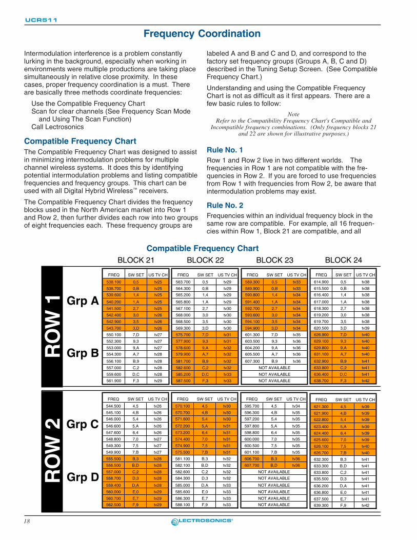
Intermodulation interference is a problem constantlylurking in the background, especially when working inenvironments were multiple productions are taking placesimultaneously in relative close proximity. In thesecases, proper frequency coordination is a must. Thereare basically three methods coordinate frequencies:
Use the Compatible Frequency ChartScan for clear channels (See Frequency Scan Mode
and Using The Scan Function)Call Lectrosonics
Compatible Frequency ChartThe Compatible Frequency Chart was designed to assistin minimizing intermodulation problems for multiplechannel wireless systems. It does this by identifyingpotential intermodulation problems and listing compatiblefrequencies and frequency groups. This chart can beused with all Digital Hybrid Wireless™ receivers.
The Compatible Frequency Chart divides the frequencyblocks used in the North American market into Row 1and Row 2, then further divides each row into two groupsof eight frequencies each. These frequency groups are
labeled A and B and C and D, and correspond to thefactory set frequency groups (Groups A, B, C and D)described in the Tuning Setup Screen. (See CompatibleFrequency Chart.)
Understanding and using the Compatible FrequencyChart is not as difficult as it first appears. There are afew basic rules to follow:
NoteRefer to the Compatibility Frequency Chart's Compatible and
Incompatible frequency combinations. (Only frequency blocks 21and 22 are shown for illustrative purposes.)
Rule No. 1Row 1 and Row 2 live in two different worlds. Thefrequencies in Row 1 are not compatible with the fre-quencies in Row 2. If you are forced to use frequenciesfrom Row 1 with frequencies from Row 2, be aware thatintermodulation problems may exist.
Rule No. 2Frequencies within an individual frequency block in thesame row are compatible. For example, all 16 frequen-cies within Row 1, Block 21 are compatible, and all
Compatible Frequency ChartBLOCK 21 BLOCK 22 BLOCK 23 BLOCK 24
FREQ SW SET US TV CH FREQ SW SET US TV CH FREQ SW SET US TV CH FREQ SW SET US TV CH
538.100 0,5 tv25 563.700 0,5 tv29 589.300 0,5 tv33 614.900 0,5 tv38
538.700 0,B tv25 564.300 0,B tv29 589.900 0,B tv33 615.500 0,B tv38
539.600 1,4 tv25 565.200 1,4 tv29 590.800 1,4 tv34 616.400 1,4 tv38
540.200 1,A tv25 565.800 1,A tv29 591.400 1,A tv34 617.000 1,A tv38
541.500 2,7 tv25 567.100 2,7 tv30 592.700 2,7 tv34 618.300 2,7 tv38
542.400 3,0 tv26 568.000 3,0 tv30 593.600 3,0 tv34 619.200 3,0 tv38
542.900 3,5 tv26 568.500 3,5 tv30 594.100 3,5 tv34 619.700 3,5 tv38
543.700 3,D tv26 569.300 3,D tv30 594.900 3,D tv34 620.500 3,D tv39
550.100 7,D tv27 575.700 7,D tv31 601.300 7,D tv35 626.900 7,D tv40
552.300 9,3 tv27 577.900 9,3 tv31 603.500 9,3 tv36 629.100 9,3 tv40
553.000 9,A tv27 578.600 9,A tv32 604.200 9,A tv36 629.800 9,A tv40
554.300 A,7 tv28 579.900 A,7 tv32 605.500 A,7 tv36 631.100 A,7 tv40
556.100 B,9 tv28 581.700 B,9 tv32 607.300 B,9 tv36 632.900 B,9 tv41
557.000 C,2 tv28 582.600 C,2 tv32 NOT AVAILABLE 633.800 C,2 tv41
559.600 D,C tv28 585.200 D,C tv33 NOT AVAILABLE 636.400 D,C tv41
561.900 F,3 tv29 587.500 F,3 tv33 NOT AVAILABLE 638.700 F,3 tv42
FREQ SW SET US TV CH FREQ SW SET US TV CH FREQ SW SET US TV CH FREQ SW SET US TV CH
544.500 4,5 tv26 570.100 4,5 tv30 595.700 4,5 tv34 621.300 4,5 tv39
545.100 4,B tv26 570.700 4,B tv30 596.300 4,B tv35 621.900 4,B tv39546.000 5,4 tv26 571.600 5,4 tv30 597.200 5,4 tv35 622.800 5,4 tv39
546.600 5,A tv26 572.200 5,A tv31 597.800 5,A tv35 623.400 5,A tv39
547.600 6,4 tv26 573.200 6,4 tv31 598.800 6,4 tv35 624.400 6,4 tv39
548.800 7,0 tv27 574.400 7,0 tv31 600.000 7,0 tv35 625.600 7,0 tv39
549.300 7,5 tv27 574.900 7,5 tv31 600.500 7,5 tv35 626.100 7,5 tv40
549.900 7,B tv27 575.500 7,B tv31 601.100 7,B tv35 626.700 7,B tv40
555.500 B,3 tv28 581.100 B,3 tv32 606.700 B,3 tv36 632.300 B,3 tv41
556.500 B,D tv28 582.100 B,D tv32 607.700 B,D tv36 633.300 B,D tv41
557.000 C,2 tv28 582.600 C,2 tv32 NOT AVAILABLE 633.800 C,2 tv41558.700 D,3 tv28 584.300 D,3 tv32 NOT AVAILABLE 635.500 D,3 tv41
559.400 D,A tv28 585.000 D,A tv33 NOT AVAILABLE 636.200 D,A tv41
560.000 E,0 tv29 585.600 E,0 tv33 NOT AVAILABLE 636.800 E,0 tv41
560.700 E,7 tv29 586.300 E,7 tv33 NOT AVAILABLE 637.500 E,7 tv41562.500 F,9 tv29 588.100 F,9 tv33 NOT AVAILABLE 639.300 F,9 tv42
Grp A
Grp B
Grp C
Grp D
RO
W 1
RO
W 2

19
UHF Wireless Digital HybridTM Receiver
Rio Rancho, NM – USA
Compatible Frequency Chart (cont.)BLOCK 25
FREQ SW SET US TV CH
640.500 0,5 tv42
641.100 0,B tv42
642.000 1,4 tv42
642.600 1,A tv42
643.900 2,7 tv42
644.800 3,0 tv43
645.300 3,5 tv43
646.100 3,D tv43
652.500 7,D tv44
654.700 9,3 tv44
655.400 9,A tv44
656.700 A,7 tv45
658.500 B,9 tv45
659.400 C,2 tv45
662.000 D,C tv45/46
664.300 F,3 tv46
BLOCK 26 BLOCK 27 BLOCK 28 BLOCK 29
FREQ SW SET US TV CH FREQ SW SET US TV CH FREQ SW SET US TV CH FREQ SW SET US TV CH
666.100 0,5 tv46 691.700 0,5 tv50 717.300 0,5 tv55 742.900 0,5 tv59
666.700 0,B tv46 692.300 0,B tv51 717.900 0,B tv55 743.500 0,B tv59
667.600 1,4 tv46 693.200 1,4 tv51 718.800 1,4 tv55 744.400 1,4 tv59
668.200 1,A tv47 693.800 1,A tv51 719.400 1,A tv55 745.000 1,A tv59
669.500 2,7 tv47 695.100 2,7 tv51 720.700 2,7 tv55 746.300 2,7 tv60
670.400 3,0 tv47 696.000 3,0 tv51 721.600 3,0 tv55 747.200 3,0 tv60
670.900 3,5 tv47 696.500 3,5 tv51 722.100 3,5 tv56 747.700 3,5 tv60
671.700 3,D tv47 697.300 3,D tv51 722.900 3,D tv56 748.500 3,D tv60
678.100 7,D tv48 703.700 7,D tv52 729.300 7,D tv57 754.900 7,D tv61
680.300 9,3 tv49 705.900 9,3 tv53 731.500 9,3 tv57 757.100 9,3 tv61
681.000 9,A tv49 706.600 9,A tv53 732.200 9,A tv57 757.800 9,A tv61
682.300 A,7 tv49 707.900 A,7 tv53 733.500 A,7 tv57 759.100 A,7 tv62
684.100 B,9 tv49 709.700 B,9 tv53 735.300 B,9 tv58 760.900 B,9 tv62
685.000 C,2 tv49 710.600 C,2 tv54 736.200 C,2 tv58 761.800 C,2 tv62
687.600 D,C tv50 713.200 D,C tv54 738.800 D,C tv58 764.400 D,C tv63
689.900 F,3 tv50 715.500 F,3 tv54 741.100 F,3 tv59 766.700 F,3 tv63
FREQ SW SET US TV CH FREQ SW SET US TV CH FREQ SW SET US TV CH FREQ SW SET US TV CH FREQ SW SET US TV CH
646.900 4,5 tv43 672.500 4,5 tv47 698.100 4,5 tv52 723.700 4,5 tv56 749.300 4,5 tv60
647.500 4,B tv43 673.100 4,B tv47 698.700 4,B tv52 724.300 4,B tv56 749.900 4,B tv60
648.400 5,4 tv43 674.000 5,4 tv47/48 699.600 5,4 tv52 725.200 5,4 tv56 750.800 5,4 tv60
649.000 5,A tv43 674.600 5,A tv48 700.200 5,A tv52 725.800 5,A tv56 751.400 5,A tv60
650.000 6,4 tv43/44 675.600 6,4 tv48 701.200 6,4 tv52 726.800 6,4 tv56 752.400 6,4 tv61
651.200 7,0 tv44 676.800 7,0 tv48 702.400 7,0 tv52 728.000 7,0 tv56/57 753.600 7,0 tv61
651.700 7,5 tv44 677.300 7,5 tv48 702.900 7,5 tv52 728.500 7,5 tv57 754.100 7,5 tv61
652.300 7,B tv44 677.900 7,B tv48 703.500 7,B tv52 729.100 7,B tv57 754.700 7,B tv61
657.900 B,3 tv45 683.500 B,3 tv49 709.100 B,3 tv53 734.700 B,3 tv58 760.300 B,3 tv62
658.900 B,D tv45 684.500 B,D tv49 710.100 B,D tv54 735.700 B,D tv58 761.300 B,D tv62
659.400 C,2 tv45 685.000 C,2 tv49 710.600 C,2 tv54 736.200 C,2 tv58 761.800 C,2 tv62
661.100 D,3 tv45 686.700 D,3 tv50 712.300 D,3 tv54 737.900 D,3 tv58 763.500 D,3 tv62
661.800 D,A tv45 687.400 D,A tv50 713.000 D,A tv54 738.600 D,A tv58 764.200 D,A tv63
662.400 E,0 tv46 688.000 E,0 tv50 713.600 E,0 tv54 739.200 E,0 tv58 764.800 E,0 tv63
663.100 E,7 tv46 688.700 E,7 tv50 714.300 E,7 tv54 739.900 E,7 tv58 765.500 E,7 tv63
664.900 F,9 tv46 690.500 F,9 tv50 716.100 F,9 tv55 741.700 F,9 tv59 767.300 F,9 tv63
CompatibleThe following frequencycombinations have nointermodulation prob-lems.
IncompatibleThe following frequencycombinations haveintermodulation prob-lems and should not beused.
BLOCK 21 BLOCK 22
FREQ SW SET US TV CH FREQ SW SET US TV CH
538.100 0,5 tv25 563.700 0,5 tv29
538.700 0,B tv25 564.300 0,B tv29
539.600 1,4 tv25 565.200 1,4 tv29
540.200 1,A tv25 565.800 1,A tv29
541.500 2,7 tv25 567.100 2,7 tv30
542.400 3,0 tv26 568.000 3,0 tv30
542.900 3,5 tv26 568.500 3,5 tv30
543.700 3,D tv26 569.300 3,D tv30
550.100 7,D tv27 575.700 7,D tv31
552.300 9,3 tv27 577.900 9,3 tv31
553.000 9,A tv27 578.600 9,A tv32
554.300 A,7 tv28 579.900 A,7 tv32
556.100 B,9 tv28 581.700 B,9 tv32
557.000 C,2 tv28 582.600 C,2 tv32
559.600 D,C tv28 585.200 D,C tv33
561.900 F,3 tv29 587.500 F,3 tv33
FREQ SW SET US TV CH FREQ SW SET US TV CH
544.500 4,5 tv26 570.100 4,5 tv30
545.100 4,B tv26 570.700 4,B tv30
546.000 5,4 tv26 571.600 5,4 tv30
546.600 5,A tv26 572.200 5,A tv31
547.600 6,4 tv26 573.200 6,4 tv31
548.800 7,0 tv27 574.400 7,0 tv31
549.300 7,5 tv27 574.900 7,5 tv31
549.900 7,B tv27 575.500 7,B tv31
555.500 B,3 tv28 581.100 B,3 tv32
556.500 B,D tv28 582.100 B,D tv32
557.000 C,2 tv28 582.600 C,2 tv32
558.700 D,3 tv28 584.300 D,3 tv32
559.400 D,A tv28 585.000 D,A tv33
560.000 E,0 tv29 585.600 E,0 tv33
560.700 E,7 tv29 586.300 E,7 tv33
562.500 F,9 tv29 588.100 F,9 tv33
Grp A
Grp B
Grp C
Grp D
RO
W 1
RO
W 2
BLOCK 21
FREQ SW SET US TV CH
538.100 0,5 tv25
538.700 0,B tv25
539.600 1,4 tv25
540.200 1,A tv25
541.500 2,7 tv25
542.400 3,0 tv26
542.900 3,5 tv26
543.700 3,D tv26
550.100 7,D tv27
552.300 9,3 tv27
553.000 9,A tv27
554.300 A,7 tv28
556.100 B,9 tv28
557.000 C,2 tv28
559.600 D,C tv28
561.900 F,3 tv29
FREQ SW SET US TV CH
544.500 4,5 tv26
545.100 4,B tv26
546.000 5,4 tv26
546.600 5,A tv26
547.600 6,4 tv26
548.800 7,0 tv27
549.300 7,5 tv27
549.900 7,B tv27
555.500 B,3 tv28
556.500 B,D tv28
557.000 C,2 tv28
558.700 D,3 tv28
559.400 D,A tv28
560.000 E,0 tv29
560.700 E,7 tv29
562.500 F,9 tv29
Grp A
Grp B
Grp C
Grp D
RO
W 1
RO
W 2
BLOCK 21 BLOCK 22
FREQ SW SET US TV CH FREQ SW SET US TV CH
538.100 0,5 tv25 563.700 0,5 tv29
538.700 0,B tv25 564.300 0,B tv29
539.600 1,4 tv25 565.200 1,4 tv29
540.200 1,A tv25 565.800 1,A tv29
541.500 2,7 tv25 567.100 2,7 tv30
542.400 3,0 tv26 568.000 3,0 tv30
542.900 3,5 tv26 568.500 3,5 tv30
543.700 3,D tv26 569.300 3,D tv30
550.100 7,D tv27 575.700 7,D tv31
552.300 9,3 tv27 577.900 9,3 tv31
553.000 9,A tv27 578.600 9,A tv32
554.300 A,7 tv28 579.900 A,7 tv32
556.100 B,9 tv28 581.700 B,9 tv32
557.000 C,2 tv28 582.600 C,2 tv32
559.600 D,C tv28 585.200 D,C tv33
561.900 F,3 tv29 587.500 F,3 tv33
FREQ SW SET US TV CH FREQ SW SET US TV CH
544.500 4,5 tv26 570.100 4,5 tv30
545.100 4,B tv26 570.700 4,B tv30
546.000 5,4 tv26 571.600 5,4 tv30
546.600 5,A tv26 572.200 5,A tv31
547.600 6,4 tv26 573.200 6,4 tv31
548.800 7,0 tv27 574.400 7,0 tv31
549.300 7,5 tv27 574.900 7,5 tv31
549.900 7,B tv27 575.500 7,B tv31
555.500 B,3 tv28 581.100 B,3 tv32
556.500 B,D tv28 582.100 B,D tv32
557.000 C,2 tv28 582.600 C,2 tv32
558.700 D,3 tv28 584.300 D,3 tv32
559.400 D,A tv28 585.000 D,A tv33
560.000 E,0 tv29 585.600 E,0 tv33
560.700 E,7 tv29 586.300 E,7 tv33
562.500 F,9 tv29 588.100 F,9 tv33
Grp A
Grp B
Grp C
Grp D
RO
W 1
RO
W 2

20
UCR511
frequencies in Row 2 Block 21 are compatible. However,frequencies in Row 1, Block 21 are not compatible withthe frequencies in Row 2, Block 21. If possible, it ishighly recommeneded to choose frequencies that are inthe same row and same group. For example, stick withfrequencies in Row 1 Group A, or Row 2 Group D ratherthan choosing frequencies from Row 1 Groups A and B.
Rule No. 3Some frequencies in adjacent blocks are compatible andsome are not. Refer to the illustration to the left whichshows compatible and incompatible frequency relation-ships.
By following the three rules, it is possible to locate anumber of potential clear operating frequencies early inthe production that are intermodulation free, then refinethe list during system setup.
Using the Scan FunctionRefer to the section titled "Frequency Scan Mode" fordetails on how to use the built-in spectrum scanner.Interference can result from a wide variety of sourcesincluding TV station signals and other wireless equip-ment in use nearby. The RF spectrum analyzer built intothe UCR511 scans the frequency block to identify
channels with little or no interference. After scanningand finding the needed number of clear channels, onefinal procedure is necessary to verify the compatibility ofthe chosen frequencies.
Turn on all transmitters and receivers used for theprogram and verify there is a strong RF signal for eachreceiver. Turn each transmitter off one at a time andobserve the RF level indicator on the matching receiver.The RF level should disappear or drop to a very lowlevel. If it does not, change frequency on that receiverand transmitter and try it again.
Any time a frequency is changed on any of the systemsin use, you must start at the beginning and go throughthis procedure for all systems. This will test for higherorder imtermodulation from all signal sources and avoidinterference.
Call LectrosonicsLectrosonics uses a proprietary computer program toperform thousands of calculations and identify variousinterfering signals. Potential problems and trouble areascan be identified in advance, and proposed new frequen-cies or other solutions can be suggested. This service isoffered to authorized Lectrosonics dealers and othercustomers who are using LECTRO™ or Lectrosonics®
wireless microphone and wireless IFB systems.

21
UHF Wireless Digital HybridTM Receiver
Rio Rancho, NM – USA
UCR511 REPLACEMENT PARTS AND ACCESSORIESPart No. Description
32251 Velcro mounting strips
CCMINI Zippered, padded vinyl system pouch
CH12E AC power supply with US type 2-pin plug onhousing, 110 VAC input; 12 VDC, 2.8 A output.
VSR1 Thin velcro loop for power cable strain relief.
A8U UHF marine phosphor bronze antenna -straight connector, specify block.
A500RA UHF flexible whip antenna with right angleBNC connector (470 - 608 MHz)
PS70 A/C power supply with US type 2-pin plug onhousing, 110 VAC input; 12 VDC, 2.8 A output.
UM500 Belt-pack Digital Hybrid WirelessTM transmitterwith over 50 mW power.
UMC200D Rack-mount multicoupler combining antennaand power distribution for up to four Lectroson-ics wireless microphone receivers. Includesbuilt-in power supply.
SIXPACK Portable multicoupler for field productioncombining antenna and power distribution forup to six Lectrosonics wireless microphonereceivers. Includes built-in rechargeablebattery pack for added mobility.
SNA600 Collapsible dipole antenna adjustable from 550MHz to 800 MHz. Ideal for situations where afull 360 degree receiving pattern is required asopposed to a directional pattern.
ALP600 “Shark fin” Log Periodic Dipole Array (LPDA)provides useful directional pattern over 500 to800 MHz range. Ideal for portable applicationsincluding temporary setups for field production.Not intended to be left outdoors permanently.
ALP700A LPDA (Log Periodic Dipole Array) providesuseful directional pattern over a broad fre-quency bandwidth (500 to 800 MHz).
ARG15-ARG100 Coaxial cables for remote antennas areavailable from Lectrosonics in a variety oflengths - from 2 to 100 ft. Cables include Velcrotie wraps.

22
UCR511
Symptom Possible Causes
INITIAL POWER ONLCD display not active or lit. External power supply disconnected or inadequate.
Main power supply fuse tripped. Turn the receiver off, remove thecause of the overload and turn the receiver back on.
Wrong polarity power source. The external DC in requiresPOSITIVE to be on the center pin.
Battery may be low. Try a fresh battery
Version message shows DSP or COM. This indicates an internal error. Please contact the factory forassistance.
Display indicates CHECK FREQ.This is a warning that a strong signal is present but it’s far enough
away from the center of the channel that the audio is likely to bedistorted. Try relocating to unused frequencies. If this doesn’tremove the warning mesasge, the transmitter or receiver mayneed repair.
PILOT TONE SQUELCHPILOT indicator is solid “P”,but no sound Audio output cable bad or disconnected.
Audio Output level set too low. Use the built-in test tone to verifylevels.
PILOT “P” keeps flashing whentransmitter audio switch is turned on Pilot tone detection can take several seconds. Turn on the
transmitter power (and the audio switch on some models) andwait 3 to 5 seconds for the “P” to indicate steadily.
Transmitter and receiver not on same frequency.Receiver compatibility mode does not match the trasmitter in use.
(See Menu Selections from Main Window, COMPAT.)
Noise on audio and Pilot indicator is “b” The pilot tone bypass has been activated. Hold MENU and pressUP to reset (works only from the Main Window).
Pilot indicator not present but audio is being receivedReceiver is set to a compatibility mode that doesn’t use Pilot Tone.
Check that receiver compatibility mode matches the transmitterin use as any sufficiently strong signal can unsquelch thereceiver in this mode, compatible or not.
NOTE: In the 500 Series and 300 Series compatibility modes, thePILOT indicator on the front panel shows as a solid “P” to
indicate that the audio has been turned on at thetransmitter, and that the audio output on the receiver is
enabled. When the “P” is on, the audio is enabled. If the“P” is flashing the pilot tone is not detected and the audio
will be muted (squelched).
In the other compatibility modes, no pilot tone is used andthe “P” is never displayed. Audio is present whenever the
receiver detects a sufficiently strong signal.
Regardless of the compatibility mode, activating the “pilotbypass” function causes a lowercase “b” to appear in thepilot indicator position on the main window and forcibly
unsquelches the audio.
ANTENNAS AND RF SIGNAL STRENGTHRF Level is weak Receiver may need to be moved or reoriented.
Antenna on transmitter may be defective or poorly connected -double check antenna on transmitter.
Improper length of antenna, or wrong antenna on transmitter orreceiver. UHF whip antennas are generally about 3 to 5 inches
TROUBLESHOOTING

23
UHF Wireless Digital HybridTM Receiver
Rio Rancho, NM – USA
long. UHF helical antennas may be shorter, but are often lessefficient.
No RF Signal Make certain frequency switches on transmitter match the
receiver frequency setting.Check battery in transmitter
AUDIO SIGNAL QUALITYPoor signal to noise ratio Transmitter gain set too low
The noise may not be in the wireless system. Turn the transmitteraudio gain all the way down and see if the noise remains. If thenoise remains, then turn the power off at the transmitter and seeif it remains. If the noise is still present, then the problem is notin the transmitter.
If noise is still present when the transmitter is turned off, trylowering the audio output level on the UCR511 and see if thenoise lowers correspondingly. If the noise remains, the problemis not in the receiver.
Receiver output is too low for the input of the device it is feeding.Try increasing the output level of the UCR511 and lowering theinput gain on the device the UCR511 is feeding.
DistortionTransmitter input gain too high. Check and/or readjust input gain on
transmitter according to the LEDs on the transmitter and thenverify the setting with the audio meter in the main window.
Audio output level too high for the device the UCR511 is feeding.Lower the output level of the UCR511.
Bad frequency response or generallypoor audio quality. Ensure the receiver is set to the compatibility mode that matches
the transmitter in use.

24
UCR511
Operating Frequencies (MHz):
Block 525:525.000 - 550.500
Block 21: 537.600 - 563.100Block 22: 563.200 - 588.700Block 23: 588.800 - 614.300
Block 24: 614.400 - 639.900Block 25: 640.000 - 665.500Block 26: 665.600 - 691.100Block 27: 691.200 - 716.700Block 28: 716.800 - 742.300Block 29: 742.400 - 767.900Block 30: 768.000 - 793.500Block 31: 793.600 - 805.600Block 32: 819.200 - 844.700Block 31: 844.800 - 862.000
Frequency Adj. Range: 25.5 MHz in 100kHz steps
Receiver Type: Triple conversion, superheterodyne, 244MHz, 10.7 MHz and 300 kHz
Frequency Stability: ±0.001 %
Front end bandwidth: ±5.5 MHz @ -3 dB
Sensitivity
20 dB Sinad: 0.9 uV (-108 dBm), A weighted
60 dB Quieting: 1.12 uV (-105 dBm), A weighted
Squelch quieting: Greater than 100 dB
AM rejection: Greater than 60 dB, 2 uV to 1 Volt(Undetectable after processing)
Modulation acceptance: 60 kHz
Image & spurious rejection:85 dB
Third order intercept: +8 dBm
Diversity method: Phased antenna combining SmartDiversityTM
FM Detector: Digital Pulse Counting Detector operating at300 kHz
Antenna inputs: Dual BNC female, 50 Ohm impedance
Audio outputs
Rear Panel XLR: Adjustable from -50 dBu to +5 dBuin 1 dB steps. Calibrated into a typical 10 kOhm balanced load.Can drive 600 Ohm load.
Front Panel Controls and Indicators:
LCD control panel
Main window: Pilot tone; antenna phase, receiver batterylevel; transmitter battery status; audio level,RF level
Freq. window: Frequency, TV channel Transmitter switchsetting
Audio output level
adjustment: -50 dBu to +5 dBu
Batt. level tracking: Receiver and transmitter (9 V batt.) in 1/10thvolt steps, accuracy +/- 0.2 V.
Transmitter (AA battery) x.xxV format,accuracy +/- 0.05 V.
Timer option available whentransmitter battery is set to NiMH.
SPECIFICATIONS AND FEATURES
Scanning mode: Coarse and fine modes for RF spectrum sitescanning
Audio test tone: 1 kHz, -50 dBu to +5 dBu output, less than1% THD
Transmitter battery type selection:9 V alkaline, 9V lithium, AA alkaline, AA lithium, NiMH
Phase invert: Audio output phase normal or inverted
SmartNR
(noise reduction): OFF, NORMAL, FULL modes(available in 500 Series mode only)
Audio Performance (overall system):
(These specs apply to 500 Series mode only.)
Frequency Response: 32 Hz to 20 kHz (+/- 1dB)
THD: 0.2% (typical)
SNR at receiver output (dB):
Input Dynamic Range: 125 dB (with full Tx limiting)
Rear Panel Controls and features:XLR audio output jack; External DCinput; Battery compartment access
Power Options:Ext DC: Minimum 10 Volts to maximum 18
VDC; 1.6 W, 180 mA at 12 VDC
Int Batt: 9 Volt alkaline or lithium(165 mA @ 9 V, 240 mA @ 6 V)
Battery Life:
9V alkaline 6 to 8 hours continuous, up to 12hours intermittent
9V lithium Up to 20 hours (continuous andintermittent usage are the same)
Weight: 14 oz. with batteries
Dimensions: 3.23" wide x 1.25" high x 4.64" deep
Specifications subject to change without notice
(Note: the dual envelope “soft” limiter provides exceptionally good handlingof transients using variable attack and release time constants. The gradualonset of limiting in the design begins below full modulation, which reducesthe measured figure for SNR without limiting by 4.5 dB)
SmartNR No Limiting W/ Limiting
OFF
NORMAL
FULL
102.0
105.0
106.0
106.5
109.5
110.5
25
UHF Wireless Digital HybridTM Receiver
Rio Rancho, NM – USA
SERVICE AND REPAIRIf your system malfunctions, you should attempt to correct or isolate the trouble before concluding that the equipmentneeds repair. Make sure you have followed the setup procedure and operating instructions. Check out the intercon-necting cords and then go through the TROUBLESHOOTING section in the manual
We strongly recommend that you do not try to repair the equipment yourself and do not have the local repair shopattempt anything other than the simplest repair. If the repair is more complicated than a broken wire or loose con-nection, send the unit to the factory for repair and service. Don’t attempt to adjust any controls inside the units.Once set at the factory, the various controls and trimmers do not drift with age or vibration and never require read-justment. There are no adjustments inside that will make a malfunctioning unit start working.

26
UCR511
This product meets the CE Compliance Standards - ETS 300 489; 2002-08,I ETS 300 422; August 2002 and ENG 0950-1; 2001. A copy of theDeclaration of Conformity may be requested from your dealer or bycontacting the factory directly:
Lectrosonics, Inc.Marketing Department581 Laser Rd. NE, Rio Rancho, NM 87124 USAtel: 505-892-4501 fax: 505-892-6243 e-mail: [email protected]

27
UHF Wireless Digital HybridTM Receiver
Rio Rancho, NM – USA

28
UCR511
October 22, 2004
581 LASER ROADRIO RANCHO, NM 87124 USA
www.lectrosonics.com
LIMITED ONE YEAR WARRANTY
LIMITED ONE YEAR WARRANTYThe equipment is warranted for one year from date of purchase against defects in materials or workmanship provided it was purchased from an authorized dealer. This warranty does not cover equipment which has been abused or damaged by careless handling or shipping. This warranty does not apply to used or demonstrator equipment.
Should any defect develop, Lectrosonics, Inc. will, at our option, repair or replace any defective parts without charge for either parts or labor. If Lectrosonics, Inc. cannot correct the defect in your equipment, it will be replaced at no charge with a similar new item. Lectrosonics, Inc. will pay for the cost of returning your equipment to you.
This warranty applies only to items returned to Lectrosonics, Inc. or an authorized dealer, shipping costs prepaid, within one year from the date of purchase.
This Limited Warranty is governed by the laws of the State of New Mexico. It states the entire liablility of Lectrosonics Inc. and the entire remedy of the purchaser for any breach of warranty as outlined above. NEITHER LECTROSONICS, INC. NOR ANYONE INVOLVED IN THE PRODUCTION OR DELIVERY OF THE EQUIPMENT SHALL BE LIABLE FOR ANY INDIRECT, SPECIAL, PUNITIVE, CONSEQUENTIAL, OR INCIDENTAL DAMAGES ARISING OUT OF THE USE OR INABILITY TO USE THIS EQUIPMENT EVEN IF LECTROSONICS, INC. HAS BEEN ADVISED OF THE POSSIBILITY OF SUCH DAMAGES. IN NO EVENT SHALL THE LIABILITY OF LECTROSONICS, INC. EXCEED THE PURCHASE PRICE OF ANY DEFECTIVE EQUIPMENT.
This warranty gives you specific legal rights. You may have additional legal rights which vary from state to state.