uds overview - construction documents in interior · pdf filedrawing set organization project...
TRANSCRIPT

UDS OVERVIEWUniform Drawing System
The Construction Specifications Institute601 Madison StreetAlexandria, VA
1994CSI began development of UDSOrganization and presentation of drawing setsOrganization and presentation of Sheets, schedules, and
diagramsStandards for drafting conventions and colorStandard systems for keynotes, attributes, and CAD
layering

UDS OVERVIEW
1995
UDS was accepted by:
AIATri-Service CADD/GIS Technology CenterUS Coast GuardNational Institute of Building Sciences
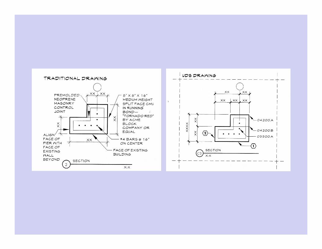
UDS provides uniformity for graphical information in drawings –Similar to MasterFormat™, Section Format™, and Page Format™ in specifications

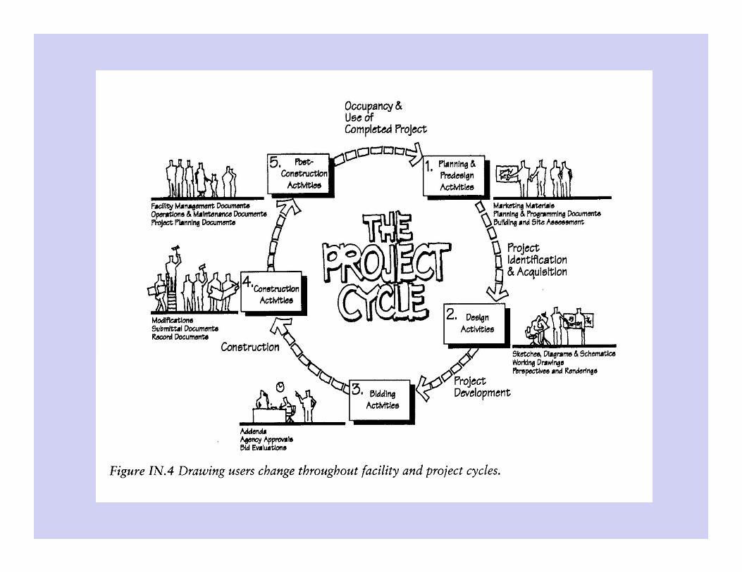
UDS OVERVIEWDrawing Users:
OwnerDesign ProfessionalsContractor
Owner’s RepConsultantSubcontractor
Material supplierProduct ManufacturerBuilding OfficialGovernment OfficialAccountantAttorneyLender
End user

UDS OVERVIEW
Modules
Drawing Set OrganizationFor use by traditional architectural and engineering
disciplinesEstablishes standard designators for disciplines and
presentation order of disciplines in document set.Establishes consistency throughout setAccommodates both simple and complex projects
Drawing Sheet OrganizationStandards for sheet sizes – both metric and inch-pound
systemsProvides a grid system of blocks for organizing informationFormat for title block

UDS OVERVIEWModules, Con’t
SchedulesConsistent format, heading terminology, and content
organizationGroups and identifies schedule types – based on
MasterFormat™ Numbers
LayeringAIA, CAD layer Standards – with updates from CSI
Drafting ConventionsSymbols, Material indications, line types, dimensions,
drawing scale, diagrams, notation, terminology and abbreviations

UDS OVERVIEW
Modules, Con’t
CAD StandardsReference filesPresentation and model viewsPen assignmentsPlotting guidelinesData exchange
ColorStandards for construction drawings

UDS OVERVIEW
DrawingsPlansElevationsSectionsLarge Scale ViewsDetailsSchedulesDiagrams3D Representations

Drawing Set Organization
Set Content and Order
Sheet IdentificationDiscipline DesignatorsModifiersSheet numbering sequence
File NamingProject Flies – specific drawings and sheetsLibrary Files
Generic and template files
Drawing Set Organization
Set Content and Order
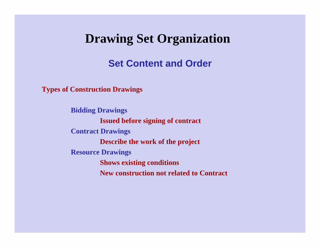
Types of Construction Drawings
Bidding DrawingsIssued before signing of contract
Contract DrawingsDescribe the work of the project
Resource DrawingsShows existing conditionsNew construction not related to Contract
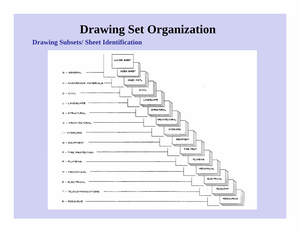
Drawing Set OrganizationDrawing Subsets/ Sheet Identification
Drawing Set Organization
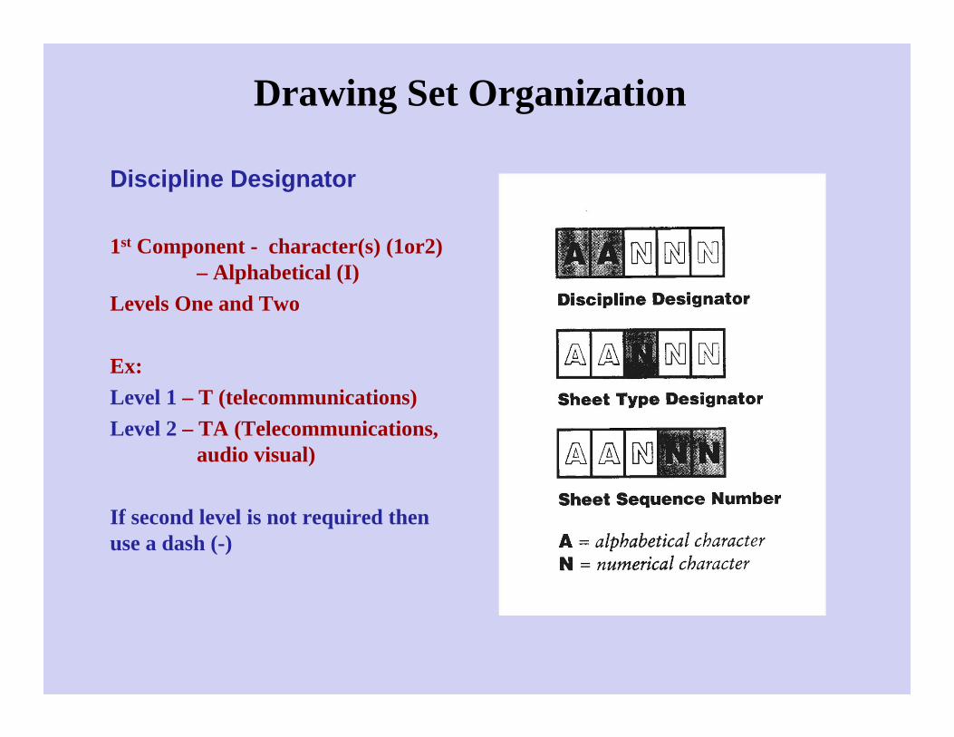
Discipline Designator
1st Component - character(s) (1or2) – Alphabetical (I)
Levels One and Two
Ex: Level 1 – T (telecommunications)Level 2 – TA (Telecommunications,
audio visual)
If second level is not required then use a dash (-)

Drawing Set OrganizationDiscipline Designator
Level 1G - General
Cover SheetIndex Sheet
H - Hazardous MaterialsC - CivilL - LandscapeS - StructuralA – Architectural
Level 2:AS – Architectural siteAD – Architectural DemolitionAE – Architectural ElementsAI – Architectural InteriorsAF – Architectural FinishesAG – Architectural Graphics
Drawing Set Organization
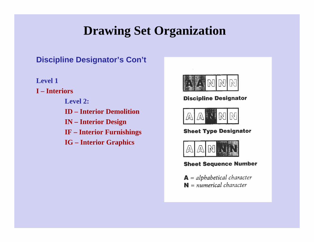
Discipline Designator’s Con’t
Level 1I – Interiors
Level 2:ID – Interior DemolitionIN – Interior DesignIF – Interior FurnishingsIG – Interior Graphics

Drawing Set Organization
Discipline Designators, Con’t
Level 1Q - EquipmentF - Fire ProtectionP - PlumbingM - MechanicalE - ElectricalT - TelecommunicationsR – ResourceX – Other DisciplinesZ – Contractor/Shop Drawings

Drawing Set OrganizationSheet Type Designator – 2nd Component – Numerical (I-1)
0 – General1 – Plans2 – Elevations3 – Sections4 – Large Scale Views5 – Details6 – Schedules and Diagrams7 – User Defined8 – User Defined9 – 3D Representations
Remember, sheet type designators do not preclude combining different types of drawings
Ex: Place schedules on a sheet when the information is closely associated

Drawing Set Organization
Sheet Sequence Designator – 3rd Component – a two-character number.
Ex: 01, 02, 03 (I-101)

Drawing Set OrganizationSupplemental Drawings
If revisions are extensive (revision cloud not feasible) the a new sheet must be altered. A user defined suffix would the be used
R – Revised – smaller scopeX – Complete changes
Ex: (I-101R1)
Drawing Set Organization
File Naming
Consistent file naming and folder structures are necessary for management of information that is reusable from project to project
CategoriesLibrary Files Project Files

Drawing Set Organization
Library Files
The library file would be copied to the drawing and assigned a file name appropriate to the project.:
DetailsSchedulesTextDatabaseSymbolsBordersTitleblockEtc.
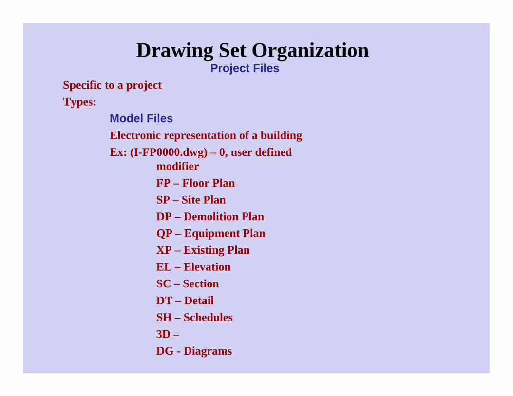
Drawing Set OrganizationProject Files
Specific to a projectTypes:
Model FilesElectronic representation of a buildingEx: (I-FP0000.dwg) – 0, user defined
modifierFP – Floor PlanSP – Site PlanDP – Demolition PlanQP – Equipment PlanXP – Existing PlanEL – ElevationSC – SectionDT – DetailSH – Schedules3D –DG - Diagrams

Drawing Set OrganizationProject Files
Types:Detail Files
A specific type of model file.Detail indicator represents its position on the drawing
detail sheetEx: (I-501-B3.dwg)Sheet position system will be discussed later
Sheet FilesName should be consistent with the sheet identification category of the physical drawing.
Schedule FilesOften produced by software other than CADIf CAD software is used the schedule should be
created full sizeDesignate similar to the Detail file – indicating the
position on the drawing sheetEx: (I-601-D1)

Drawing Set OrganizationProject Files
Types:Text Files
Usable from one project to anotherGeneral NotesDiscipline specific NotesSymbol LegendsThis is a library fileOnce imbedded in a drawing a new file name is not
neededDatabase Files
ExamplesAny scheduleInventory listingsMaster KeynotesSo, this depends on the linkage of the file.
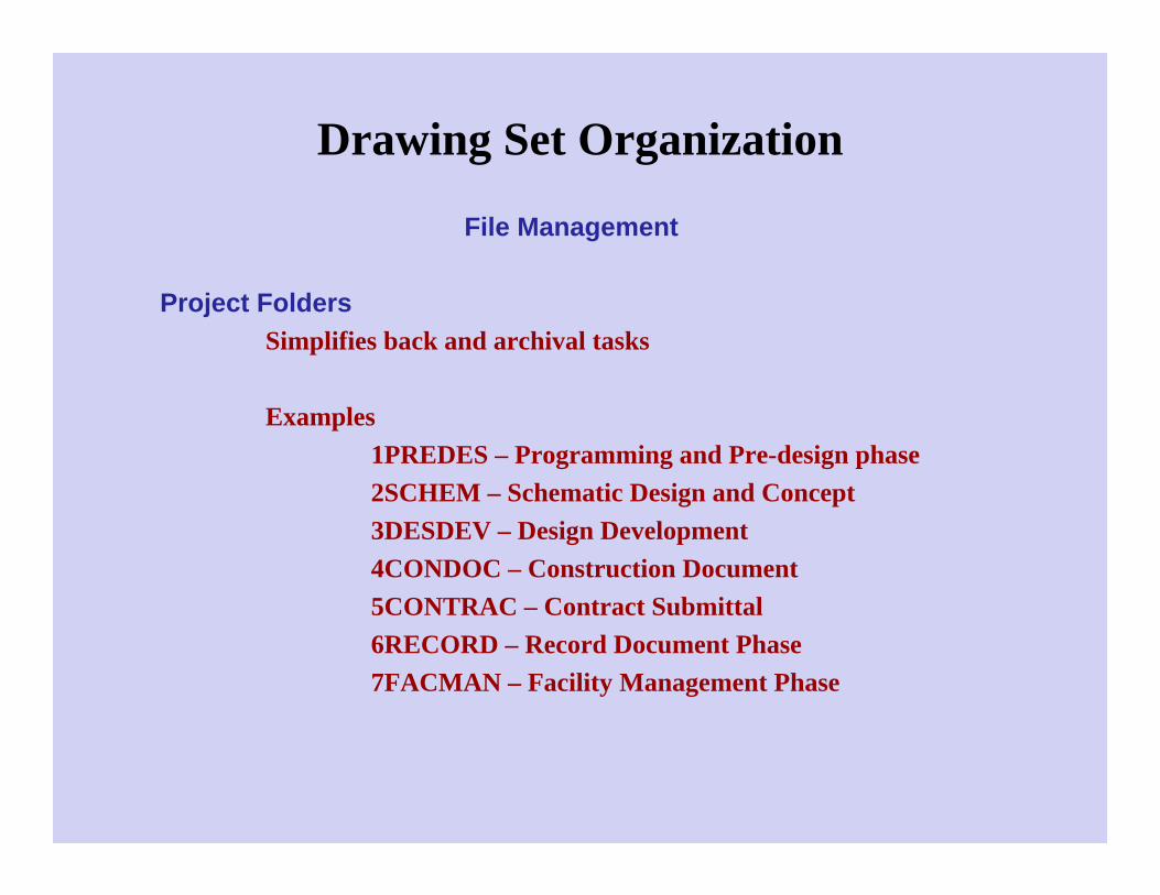
Drawing Set Organization
File Management
Project FoldersSimplifies back and archival tasks
Examples1PREDES – Programming and Pre-design phase2SCHEM – Schematic Design and Concept3DESDEV – Design Development4CONDOC – Construction Document5CONTRAC – Contract Submittal6RECORD – Record Document Phase7FACMAN – Facility Management Phase
Drawing Sheet Organization
Benefits of Sheet Organization
Provides a consistent sheet formatProvides location system for drawings on sheetEnhanced communication among drawing preparers and
usersImproved quality control – less risk of errorEasier data managementCoordinated images among disciplines

Drawing Sheet Organization Sheet Sizes
The most important determinant is selecting a size that will allow placing the floor plan on a single sheet
When plans are divided, a key plan on each plan sheet is necessary to indicate sector
ArchitecturalA – 9x12 Project book, supplemental drawings, Mock-up
sheetsB – 12x18 Reduced drawings from “D” size, Mock-up sheetsC – 18x24 Small Projects accommodating preferred plan
scaleD – 24x36 Projects accommodating preferred scale,
Government projectsE – 36x48 Accommodating preferred scale, Mapping and GISF – 30x42 Accommodating preferred scale


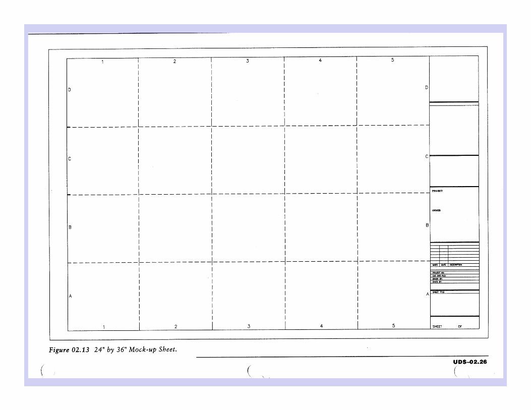
Drawing Sheet Organization
Sheet Layout
Drawing AreaTitle Block Area
Minimum Sheet Margins:
Top and bottom 3/4”Left Margin 1-1/2”Right Margin 3/4”

Drawing Sheet Organization Drawing Area
Divided into modulesModule size (approx) – 5-3/4”high x 6”wideDrawing Area Coordinate System
Columns – left to right – 1, 2, 3, 4, ….Rows – Bottom to top – A, B, C, D, ….
The drawing is identified based on the lower left hand locationPreferred that coordinates are placed on all four sides and
outside drawing area – depends on plotting hardwareMinimum – place coordinates on right hand side and top or
bottomNote Block – (More on this later)
Keynotes, general notes, and key plansmost Right-hand column
Key plan is located in the lowest module of the right column


Drawing Sheet Organization
Title Block Area
Designer Identification BlockProject Identification BlockIssue BlockManagement BlockSheet Title BlockSheet Identification Block

Drawing Sheet Organization
Title Block Area
Sheet Identification BlockOptional data would be the sheet count and the total number of
sheets (set or discipline)

Drawing Sheet Organization Title Block Area
Sheet Title BlockType of information on sheetSheet may contain one or more types of drawings – notation
usually refers to major drawing

Drawing Sheet Organization Title Block Area
Management BlockDrawing project numberOwner’s contract NumberFile NumberDesign Phase NumberDrawn by:Checked by:Copyright

Drawing Sheet Organization Title Block Area
Issue BlockPhase issue datesAddendum issue datesClarification datesRevision issue dates

Drawing Sheet Organization Title Block Area
Project Identification BlockProject name and addressBuilding of facility nameConstruction phase
sequenceProject LogoOther client information –
address, phone, etc.

Drawing Sheet Organization Title Block Area
Designer Identification BlockNameAddressContact infoLogo and professional sealConsultants

Drawing Sheet Organization Title Block Area
FormatsHorizontal – Most commonly used – preferred. Allows easier
readingVertical – Sheet identification block is always horizontal
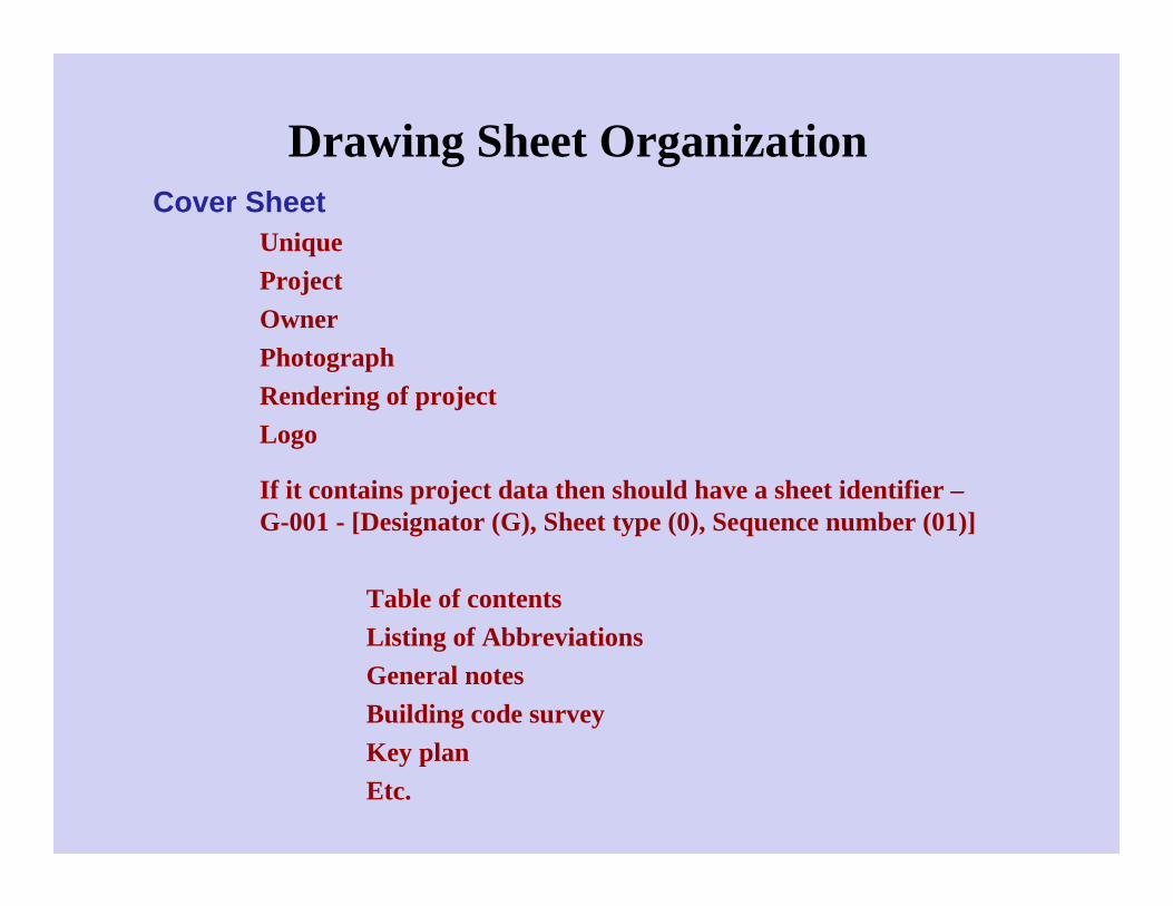
Drawing Sheet Organization Cover Sheet
UniqueProjectOwnerPhotographRendering of projectLogo
If it contains project data then should have a sheet identifier –G-001 - [Designator (G), Sheet type (0), Sequence number (01)]
Table of contentsListing of AbbreviationsGeneral notesBuilding code surveyKey planEtc.

Drawing Sheet Organization
Supplemental Drawing Sheets
9x12 or 12x18
Minimum margins – ½” except for bound edge – ¾”

Notations
Notes are part of the contract documentHave important legal consequencesTerms used in the notes must be consistent with the terms used in the
specifications
Early Twentieth CenturyDrawings were primarily graphicNotes were used sparingly affording the opportunity to provide
additional information in the field (architect and engineer)
Keying became a standard method for improving drawing clarity through reduction is the amount of text

Notations
Types of Notes – Five
General NotesGeneral Discipline NotesGeneral Sheet NotesReference KeynotesSheet Keynotes

Notations
General Notes
Located in the General Drawings Sheet Types (G)Apply to the entire workNot necessary or desirable to repeat these notes on
subsequent sheets
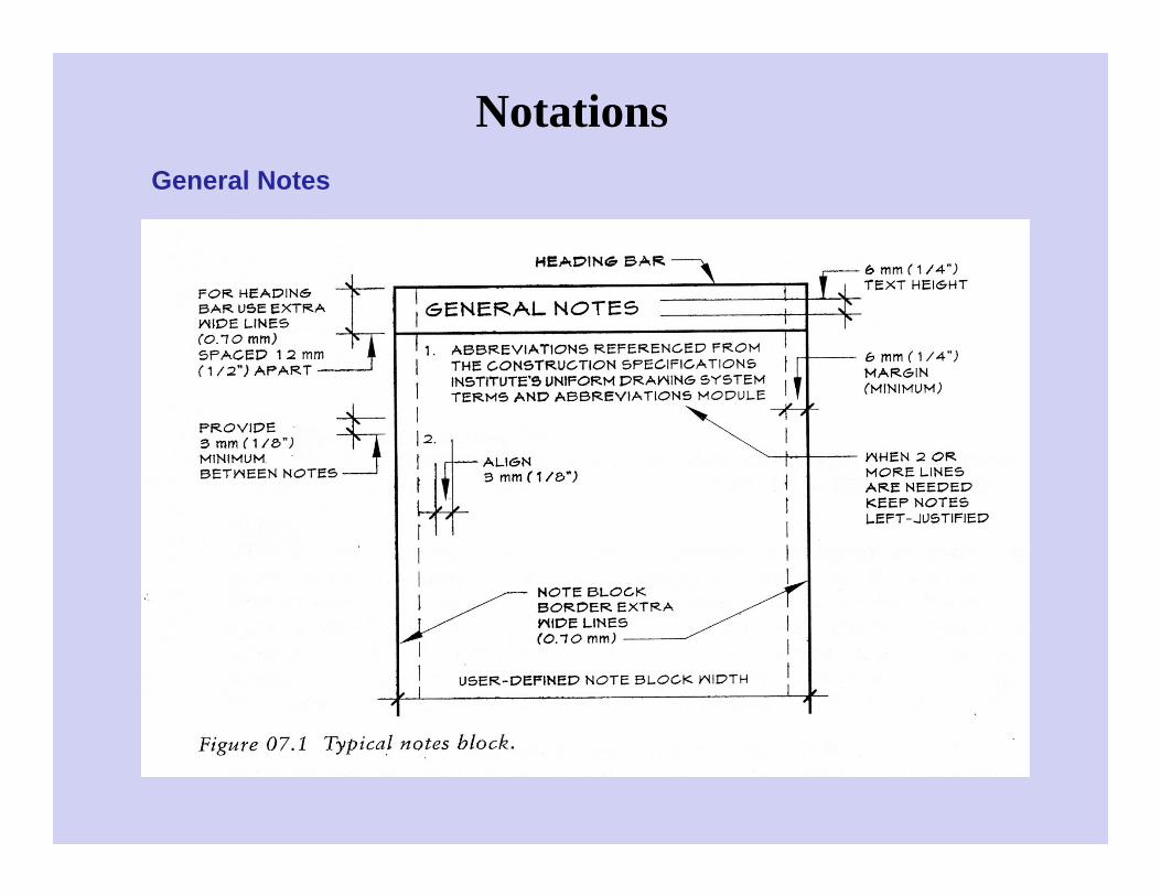
NotationsGeneral Notes

Notations
General Discipline Notes
Located on the first or “O” series sheets within a discipline
Should not be repeated on other sheets of that discipline
Instruction concerning discipline specific drafting conventions
Coordinate with other project information
General Architectural NotesGeneral Structural NotesGeneral Mechanical NotesGeneral Interior Design Notes
Notations
General Sheet Notes
Sheet specific information or instructionsSequential orderThey Follow:
General NotesGeneral Discipline Notes
They PrecedeReference KeynotesSheet Keynotes
Ex:“Dimensions on this sheet drawn to partition walls are to face of stud unless noted otherwise”


Notations
Reference KeynotesReference graphic representations to specific sections
in the specifications
Sheet KeynotesSpecific notes related to graphic information on the
sheet
Drawn with a hexagonal symbol
The bottom of the symbol should be drawn parallel to the bottom of the sheet
Numerals are sequential
They Follow sheet reference keynotes if used


Notations
Note Block Hierarchy
Position notes within the note Block – as developed for the sheet
Remember to leave space for sheet key plan if using
General Notes are first in the note block
If more than on column is needed, shift first column to the left and add another column


Notations
Users’ guide
Generic terminology should be based on well known, commonly available sources – CSI Terms and abbreviations Module
Drawing notes should match the terminology in the specifications
It is not a good practice to repeat proprietary names, model numbers, and other detailed information within the drawing notes
Fonts should be capitalized, proportional, san-serif, and non stylized. Do not use italics, underlining, bold
Try to avoid abbreviations. If abbreviations are necessary, they should be coordinated throughout drawing
If reference to a specification, then be specific