ufad energyplus model: plenum and ras testing and modeling · • ready for next release of...
TRANSCRIPT
UFAD EnergyPlus Model October 2005
Not to be reproduced without permission from the UC Regents
Center for the Built Environment (CBE)
http://www.cbe.berkeley.edu/
Page 1
CENTER FOR THE BUILT ENVIRONMENT OCTOBER 2005
CBEFred Bauman, Tom Webster, and many others
UFAD EnergyPlus Model:Plenum and RAS Testing and Modeling
CENTER FOR THE BUILT ENVIRONMENT OCTOBER 2005
Energy performance of UFAD systems
Goal/Significance• Develop a version of the whole-building energy simulation program,
EnergyPlus, capable of modeling UFAD systems• This will be the first validated UFAD energy simulation tool
Project details• Project start: November 1, 2002• Final report and software: February 28, 2006• Ready for next release of EnergyPlus: April 15, 2006• Primary funding ($610K) from California Energy Commission (CEC)
Public Interest Energy Research (PIER) program• Additional support from CBE,
U.S. Department of Energy, and York International

UFAD EnergyPlus Model October 2005
Not to be reproduced without permission from the UC Regents
Center for the Built Environment (CBE)
http://www.cbe.berkeley.edu/
Page 2
CENTER FOR THE BUILT ENVIRONMENT OCTOBER 2005
Research team
Center for the Built Environment, UC Berkeley• Fred Bauman• Tom Webster• Hui Jin• Wolfgang Lukaschek• Allan Daly, Taylor Engineering• Ian Doebber, Arup
Dept. of Mech. and Aero. Eng., UC San Diego• Paul Linden• Qing (Anna) Liu
Lawrence Berkeley National Laboratory• Fred Buhl
York International• Jack Geortner and others
CENTER FOR THE BUILT ENVIRONMENT OCTOBER 2005
Project Advisory Committee (PAC)
Commission Project Manager• Norm Bourassa (current), CEC• Martha Brook (former), CEC
PAC• Dru Crawley, US DOE• Dan Fisher, Oklahoma State University• Phil Haves, LBNL• Blair McCarry/Kevin Hydes, Stantec• Mike Scofield, Conservation Mechanical• Dennis Stanke, Trane• Steve Taylor, Taylor Engineering

UFAD EnergyPlus Model October 2005
Not to be reproduced without permission from the UC Regents
Center for the Built Environment (CBE)
http://www.cbe.berkeley.edu/
Page 3
CENTER FOR THE BUILT ENVIRONMENT OCTOBER 2005
Energy performance of UFAD systems
UFAD Version of EnergyPlus(LBNL)
Plenum Model(CBE)
RAS Model(UCSD)
SystemUpgrades
(LBNL)
Plenum Testing(CBE)
Full-scaleTesting
(CBE/York)
Salt TankTesting(UCSD)
CENTER FOR THE BUILT ENVIRONMENT OCTOBER 2005
Thermal performance of underfloor plenums
CFD model
Full-scale experiments
Validate model vs. test facility
Study thermal performance for range of design and operating conditions using CFD model
Develop simplified plenum model for implementation in EnergyPlus
UFAD EnergyPlus Model October 2005
Not to be reproduced without permission from the UC Regents
Center for the Built Environment (CBE)
http://www.cbe.berkeley.edu/
Page 4
CENTER FOR THE BUILT ENVIRONMENT OCTOBER 2005
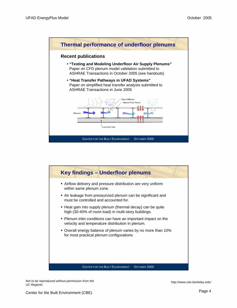
Thermal performance of underfloor plenums
Recent publications• “Testing and Modeling Underfloor Air Supply Plenums”
Paper on CFD plenum model validation submitted to ASHRAE Transactions in October 2005 (see handouts)
• “Heat Transfer Pathways in UFAD Systems”Paper on simplified heat transfer analysis submitted to ASHRAE Transactions in June 2005
CENTER FOR THE BUILT ENVIRONMENT OCTOBER 2005
Key findings – Underfloor plenums
Airflow delivery and pressure distribution are very uniform within same plenum zone.
Air leakage from pressurized plenum can be significant and must be controlled and accounted for.
Heat gain into supply plenum (thermal decay) can be quite high (30-40% of room load) in multi-story buildings.
Plenum inlet conditions can have an important impact on the velocity and temperature distribution in plenum.
Overall energy balance of plenum varies by no more than 10% for most practical plenum configurations

UFAD EnergyPlus Model October 2005
Not to be reproduced without permission from the UC Regents
Center for the Built Environment (CBE)
http://www.cbe.berkeley.edu/
Page 5
CENTER FOR THE BUILT ENVIRONMENT OCTOBER 2005
Energy performance of UFAD systems
UFAD Version of EnergyPlus(LBNL)
Plenum Model(CBE)
RAS Model(UCSD)
SystemUpgrades
(LBNL)
Plenum Testing(CBE)
Full-scaleTesting
(CBE/York)
Salt TankTesting(UCSD)
CENTER FOR THE BUILT ENVIRONMENT OCTOBER 2005
Room air stratification (RAS)
ApproachFull-scale laboratory tests of commercially available floor diffusers in realistic office setting
Study impact of various design and operating parameters on room air stratification (RAS)
Parameters investigatedType and number of diffusersDiffuser throwSupply volumeSupply temperatureRoom loadPlenum leakagePerimeter/interior zonesWindow blinds York test lab
UFAD EnergyPlus Model October 2005
Not to be reproduced without permission from the UC Regents
Center for the Built Environment (CBE)
http://www.cbe.berkeley.edu/
Page 6
CENTER FOR THE BUILT ENVIRONMENT OCTOBER 2005
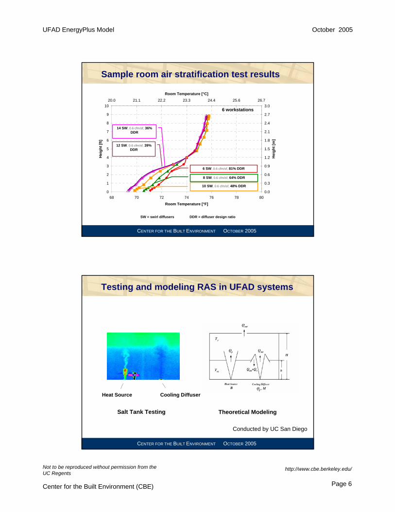
Sample room air stratification test results
0
1
2
3
4
5
6
7
8
9
10
68 70 72 74 76 78 80
Room Temperature [°F]
Hei
ght [
ft]
0.0
0.3
0.6
0.9
1.2
1.5
1.8
2.1
2.4
2.7
3.020.0 21.1 22.2 23.3 24.4 25.6 26.7
Room Temperature [°C]
Hei
ght [
m]
6 SW, 0.6 cfm/sf, 81% DDR
8 SW, 0.6 cfm/sf, 64% DDR
10 SW, 0.6 cfm/sf, 48% DDR
12 SW, 0.6 cfm/sf, 39% DDR
14 SW, 0.6 cfm/sf, 36% DDR
6 workstations
SW = swirl diffusers DDR = diffuser design ratio
CENTER FOR THE BUILT ENVIRONMENT OCTOBER 2005
Testing and modeling RAS in UFAD systems
Heat Source Cooling Diffuser
Salt Tank Testing Theoretical Modeling
Conducted by UC San Diego
UFAD EnergyPlus Model October 2005
Not to be reproduced without permission from the UC Regents
Center for the Built Environment (CBE)
http://www.cbe.berkeley.edu/
Page 7
CENTER FOR THE BUILT ENVIRONMENT OCTOBER 2005
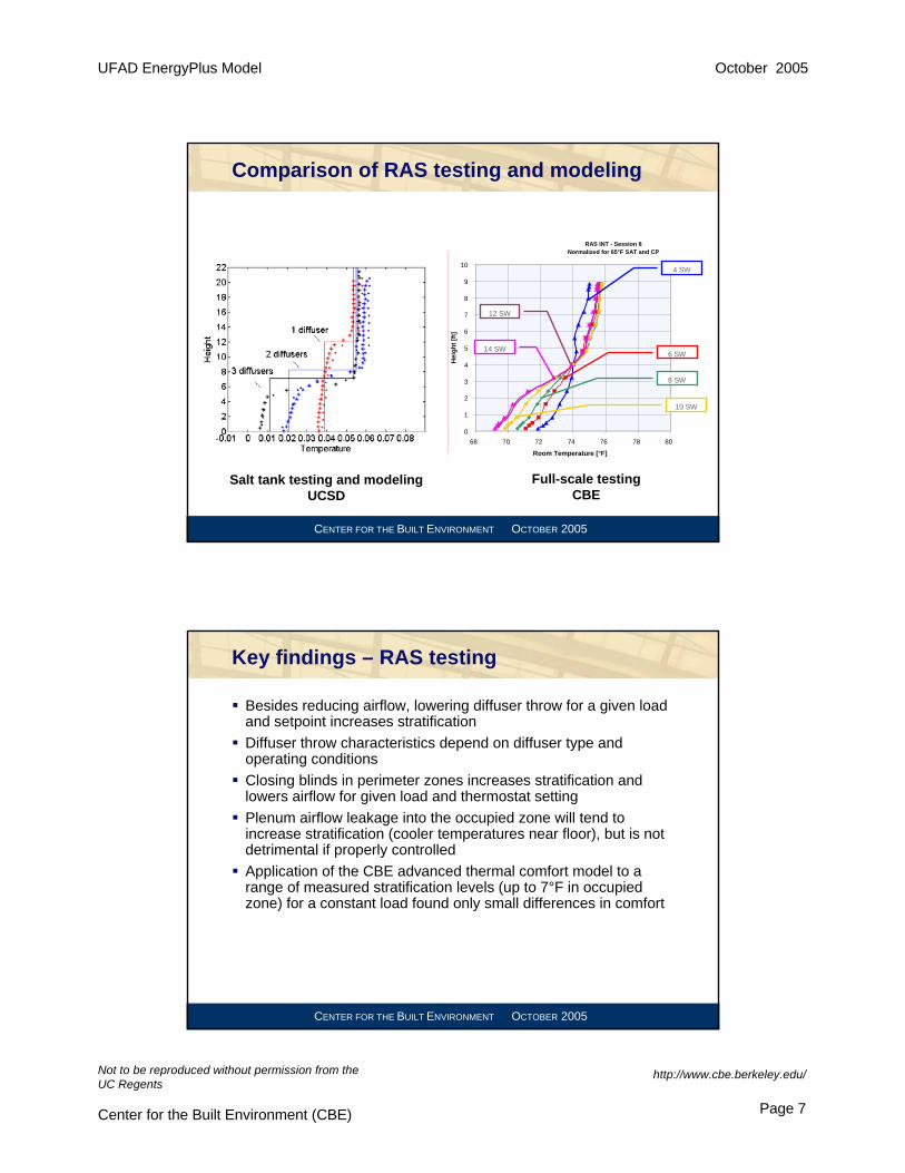
Comparison of RAS testing and modeling
RAS INT - Session 8Normalized for 65°F SAT and CP
0
1
2
3
4
5
6
7
8
9
10
68 70 72 74 76 78 80
Room Temperature [°F]H
eigh
t [ft]
4 SW
6 SW
8 SW
10 SW
12 SW
14 SW
Salt tank testing and modelingUCSD
Full-scale testingCBE
CENTER FOR THE BUILT ENVIRONMENT OCTOBER 2005
Key findings – RAS testing
Besides reducing airflow, lowering diffuser throw for a given load and setpoint increases stratificationDiffuser throw characteristics depend on diffuser type and operating conditionsClosing blinds in perimeter zones increases stratification and lowers airflow for given load and thermostat settingPlenum airflow leakage into the occupied zone will tend to increase stratification (cooler temperatures near floor), but is not detrimental if properly controlledApplication of the CBE advanced thermal comfort model to a range of measured stratification levels (up to 7°F in occupied zone) for a constant load found only small differences in comfort
UFAD EnergyPlus Model October 2005
Not to be reproduced without permission from the UC Regents
Center for the Built Environment (CBE)
http://www.cbe.berkeley.edu/
Page 8
CENTER FOR THE BUILT ENVIRONMENT OCTOBER 2005
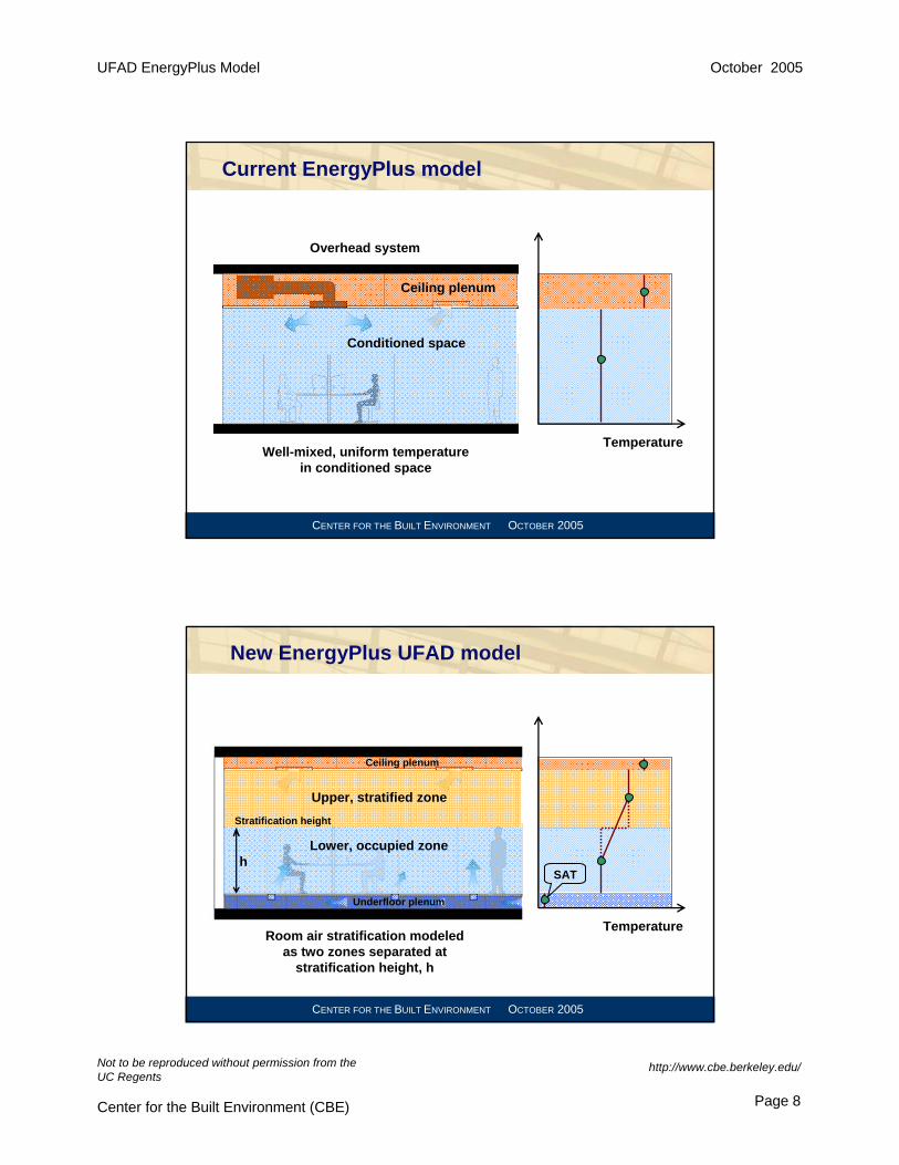
Current EnergyPlus model
Temperature
Ceiling plenum
Conditioned space
Well-mixed, uniform temperature in conditioned space
Overhead system
CENTER FOR THE BUILT ENVIRONMENT OCTOBER 2005
New EnergyPlus UFAD model
Temperature
Ceiling plenum
Room air stratification modeled as two zones separated at
stratification height, h
Underfloor plenum
Upper, stratified zone
Lower, occupied zoneh
SAT
Stratification height

UFAD EnergyPlus Model October 2005
Not to be reproduced without permission from the UC Regents
Center for the Built Environment (CBE)
http://www.cbe.berkeley.edu/
Page 9
CENTER FOR THE BUILT ENVIRONMENT OCTOBER 2005
Inputs and outputs for UFAD interior model
InputsSupply conditions
Supply temp. TsTotal airflow rate Q
DiffusersType (swirl, VA)Number n Area of each diffuser A
Heat load and plumesTotal heat load WNumber of plumes mHeat source height hs
OutputsReturn temp. TROccupied zone temp. TLStrat. height h
CENTER FOR THE BUILT ENVIRONMENT OCTOBER 2005
Validation of EnergyPlus
Comparison with full-scale RAS test dataInterior zones –Allan DalyPerimeter zones –Ian DoebberConsideration of radiation is key to make sense out of heat flows in UFAD (stratified) systems
18.8
17.8
16.2
17.4
22.5
24.223.9
29.1
24.4
24.3
24.3
23.8
23.8
17.4
13.4
23.6
0
20
40
60
80
100
120
140
160
180
10 15 20 25 30
56
63
75
76
ΔTroom=13ΔTsystem=20
75
76

UFAD EnergyPlus Model October 2005
Not to be reproduced without permission from the UC Regents
Center for the Built Environment (CBE)
http://www.cbe.berkeley.edu/
Page 10
CENTER FOR THE BUILT ENVIRONMENT OCTOBER 2005
Energy balance – Testing and EPlus modeling
-20%
0%
20%
40%
60%
80%
100%
120%
Chamber calibration test Eplus simulation
% of Total Cooling Load Leaving Room
Full-scale laboratory measurements demonstrate good room energy balance. EPlus simulations match well.
Net room cooling load = 102%
Net room cooling load = 99%
Room extraction rate
Heat transfer into plenum
Conduction through walls
CENTER FOR THE BUILT ENVIRONMENT OCTOBER 2005
Energy performance of UFAD systems
UFAD Version of EnergyPlus(LBNL)
Plenum Model(CBE)
RAS Model(UCSD)
SystemUpgrades
(LBNL)
Plenum Testing(CBE)
Full-scaleTesting
(CBE/York)
Salt TankTesting(UCSD)

UFAD EnergyPlus Model October 2005
Not to be reproduced without permission from the UC Regents
Center for the Built Environment (CBE)
http://www.cbe.berkeley.edu/
Page 11
CENTER FOR THE BUILT ENVIRONMENT OCTOBER 2005
E+ system upgrades: Variable speed fan coil
Raised Access Floor
Return Air Plenum
Return Air Grille
Linear Bar Diffuser
Flex Duct
Variable-speed fan coil
Glazing
T
Heating Coil
No U/A diffusers in perimeter zones
CENTER FOR THE BUILT ENVIRONMENT OCTOBER 2005
outside air intake
exhaust outlet
returnair
supplyair
21
09 14
bypassairreturn
air
exhaust fan
vfd
vfd
08 11
H
07
P
12 15 16
P
T 17
P
T
T
22 24
P
T
23
T
10
H
18
25
mixed airplenum
plenum fan
return airplenum
19 20
26
H
T
13
P
27
N.C.
N.O. N.O.
cooling coil
E+ system upgrades: Return air bypass
UFAD EnergyPlus Model October 2005
Not to be reproduced without permission from the UC Regents
Center for the Built Environment (CBE)
http://www.cbe.berkeley.edu/
Page 12
CENTER FOR THE BUILT ENVIRONMENT OCTOBER 2005
Next steps
Interior and perimeter zone RAS models into EPlusValidate RAS models in EPlus with full-scale dataComplete validation of plenum modelDraft final report due January 2006Final report and software due February 28, 2006Ready for next release of EnergyPlus (April 15, 2006)
CENTER FOR THE BUILT ENVIRONMENT OCTOBER 2005
Future directions with EnergyPlus/UFAD
UFAD energy analysis studyComparison with field dataInvestigate demand response performanceEnergyPlus in Title 24 EnergyPlus/UFAD training seminars