ufgs 05 30 00 steel decks - connecting repositories · 1.2 submittals 1.3 quality ... usace /...
TRANSCRIPT

**************************************************************************USACE / NAVFAC / AFCEC / NASA UFGS-05 30 00 (November 2011) Change 1 - 08/12 -----------------------------Preparing Activity: NAVFAC Superseding UFGS-05 30 00 (May 2010)
UNIFIED FACILITIES GUIDE SPECIFICATIONS
References are in agreement with UMRL dated July 2014**************************************************************************
SECTION TABLE OF CONTENTS
DIVISION 05 - METALS
SECTION 05 30 00
STEEL DECKS
11/11
PART 1 GENERAL
1.1 REFERENCES 1.2 SUBMITTALS 1.3 QUALITY ASSURANCE 1.3.1 Deck Units 1.3.2 Certification of Powder-Actuated Tool Operator 1.3.3 Qualifications for Welding Work 1.3.4 Regulatory Requirements 1.3.4.1 Fire Safety 1.3.4.2 Wind Storm Resistance 1.3.5 Fabrication Drawings 1.4 DELIVERY, STORAGE, AND HANDLING 1.5 DESIGN REQUIREMENTS FOR ROOF DECKS 1.5.1 Properties of Sections 1.5.2 Allowable Loads
PART 2 PRODUCTS
2.1 MATERIALS 2.1.1 Steel Sheet 2.1.2 Steel Coating 2.1.3 Mixes 2.1.3.1 Galvanizing Repair Paint for Floor Decks 2.1.4 Galvanized Steel Angles for Roof Decks 2.1.5 Joint Sealant Material for Roof Decks 2.1.6 Galvanizing Repair Paint for Roof Decks 2.1.7 Flexible Closure Strips for Roof Decks 2.1.8 Sound Absorbing Material 2.2 ACCESSORIES 2.2.1 Adjusting Plates 2.2.2 End Closures 2.2.3 Partition Closures 2.2.4 Closure Plates for Composite Deck 2.2.5 Sheet Metal Collar
SECTION 05 30 00 Page 1

2.2.6 Cover Plates 2.2.7 Roof Sump Pans 2.2.8 Column Closures 2.2.9 Access Hole Covers 2.2.10 Hanger 2.2.11 Shear Connectors 2.2.12 Mechanical Fasteners 2.2.13 Miscellaneous Accessories 2.3 FABRICATION 2.3.1 Deck Units 2.3.1.1 Cellular Metal Floor Deck Units 2.3.2 Length of Floor Deck Units 2.3.3 Roof Deck 2.3.3.1 Cant Strips for Roof Decks 2.3.3.2 Ridge and Valley Plates for Roof Decks 2.3.3.3 Metal Closure Stripsfor Roof Decks 2.3.4 Form Deck 2.3.5 Composite Deck 2.3.6 Acoustical Steel Deck 2.3.7 Venting 2.3.8 Shop Priming 2.3.9 Touch-Up Paint
PART 3 EXECUTION
3.1 EXAMINATION 3.2 INSTALLATION 3.2.1 Attachment 3.2.1.1 Welding 3.2.1.2 Fastening 3.2.1.3 Fastening Floor Deck Units 3.2.2 Openings 3.2.3 Deck Damage 3.2.4 Accessory Installation 3.2.4.1 Adjusting Plates 3.2.4.2 End Closures 3.2.4.3 Closures Above Partitions 3.2.4.4 Cover Plates 3.2.4.5 Column Closures 3.2.4.6 Access Hole Covers 3.2.4.7 Hangers 3.2.5 Sound Absorbing Material 3.2.6 Concrete Work 3.2.7 Preparation of Fire-Proofed Surfaces 3.3 ROOF SUMP PANS 3.4 CANT STRIPS FOR ROOF DECKS 3.5 RIDGE AND VALLEY PLATES FOR ROOF DECKS 3.6 CLOSURE STRIPS FOR ROOF DECKS 3.7 ROOF INSULATION SUPPORT FOR ROOF DECKS 3.8 CLEANING AND PROTECTION FOR ROOF DECKS 3.9 FIELD QUALITY CONTROL 3.9.1 Decks Not Receiving Concrete
-- End of Section Table of Contents --
SECTION 05 30 00 Page 2
**************************************************************************USACE / NAVFAC / AFCEC / NASA UFGS-05 30 00 (November 2011) Change 1 - 08/12 -----------------------------Preparing Activity: NAVFAC Superseding UFGS-05 30 00 (May 2010)
UNIFIED FACILITIES GUIDE SPECIFICATIONS
References are in agreement with UMRL dated July 2014**************************************************************************
SECTION 05 30 00
STEEL DECKS11/11
**************************************************************************NOTE: This guide specification covers the requirements for steel floor and roof decks, including accessories.
Adhere to UFC 1-300-02 Unified Facilities Guide Specifications (UFGS) Format Standard when editing this guide specification or preparing new project specification sections. Edit this guide specification for project specific requirements by adding, deleting, or revising text. For bracketed items, choose applicable items(s) or insert appropriate information.
Remove information and requirements not required in respective project, whether or not brackets are present.
Comments, suggestions and recommended changes for this guide specification are welcome and should be submitted as a Criteria Change Request (CCR).
**************************************************************************
**************************************************************************NOTE: Determine which roof areas on the structure are considered by the structural engineer as functioning as diaphragms for the lateral force resisting system.
Composite decks and diaphragm acting decks, including connections, should be designed by the structural engineer according to the Steel Deck Institute. Refer to the International Building Code (ICC IBC) and ICC-ES Evaluation Service Reports (ESR) based on AC43, Acceptance Criteria for Steel Deck Roof and Floor Systems, including diaphragm decks in seismic areas.All connections must be shown. Drawings must show wind uplift loads for roof joist design in addition to the items listed below.
SECTION 05 30 00 Page 3

For non-diaphragm acting, non-composite decks, the contractor may provide the deck design and connections. In this case, the drawings must show roof live loads, including snow loads, and wind loads, including internal and external pressures and high intensity zones. Consider showing a roof uplift and snow load plan on the drawings.
In addition to the above, show the following information on the project drawings:
1. Structural properties (height, sheet thickness, and section moduli or moment of inertia).
2. Floor and roof deck penetrations.
3. Location, spacing, and size of hanger clips or loops.
4. Closure plates.
5. Location of cellular decking and whether it is to be used as electrical raceway.
6. Weld or fastener spacing.
7. Whether construction is based on shored construction.
Design steel deck to carry the concrete and steel deck dead loads, and the live loads during construction before the concrete sets. Additional concrete dead load due to deflection of the deck shall be considered when necessary to prevent excessive stresses or deflections in the deck.
**************************************************************************
PART 1 GENERAL
**************************************************************************NOTE: The structural steel design must meet the requirements of OSHA Steel Erection Standard, 29 CFR Part 1926, Subpart R-Steel Erection, Effective Date January 18, 2002.
**************************************************************************
1.1 REFERENCES
**************************************************************************NOTE: This paragraph is used to list the publications cited in the text of the guide specification. The publications are referred to in the text by basic designation only and listed in this paragraph by organization, designation, date, and title.
Use the Reference Wizard's Check Reference feature when you add a RID outside of the Section's Reference Article to automatically place the
SECTION 05 30 00 Page 4

reference in the Reference Article. Also use the Reference Wizard's Check Reference feature to update the issue dates.
References not used in the text will automatically be deleted from this section of the project specification when you choose to reconcile references in the publish print process.
**************************************************************************
The publications listed below form a part of this specification to the extent referenced. The publications are referred to within the text by the basic designation only.
AMERICAN INSTITUTE OF STEEL CONSTRUCTION (AISC)
AISC 360 (2010) Specification for Structural Steel Buildings
AMERICAN IRON AND STEEL INSTITUTE (AISI)
AISI D100 (1991; R 2008) Cold-Formed Steel Design Manual
AISI SG03-3 (2002; Suppl 2001-2004; R 2008) Cold-Formed Steel Design Manual Set
AMERICAN WELDING SOCIETY (AWS)
AWS D1.1/D1.1M (2010; Errata 2011) Structural Welding Code - Steel
AWS D1.3/D1.3M (2008; Errata 2008) Structural Welding Code - Sheet Steel
ASTM INTERNATIONAL (ASTM)
ASTM A1008/A1008M (2013) Standard Specification for Steel, Sheet, Cold-Rolled, Carbon, Structural, High-Strength Low-Alloy and High-Strength Low-Alloy with Improved Formability, Solution Hardened, and Bake Hardened
ASTM A1011/A1011M (2014) Standard Specification for Steel, Sheet, and Strip, Hot-Rolled, Carbon, Structural, High-Strength Low-Alloy and High-Strength Low-Alloy with Improved Formability and Ultra-High Strength
ASTM A108 (2013) Standard Specification for Steel Bar, Carbon and Alloy, Cold-Finished
ASTM A123/A123M (2013) Standard Specification for Zinc (Hot-Dip Galvanized) Coatings on Iron and Steel Products
ASTM A36/A36M (2012) Standard Specification for Carbon Structural Steel
SECTION 05 30 00 Page 5
ASTM A653/A653M (2013) Standard Specification for Steel Sheet, Zinc-Coated (Galvanized) or Zinc-Iron Alloy-Coated (Galvannealed) by the Hot-Dip Process
ASTM A780/A780M (2009) Standard Practice for Repair of Damaged and Uncoated Areas of Hot-Dip Galvanized Coatings
ASTM A792/A792M (2010) Standard Specification for Steel Sheet, 55% Aluminum-Zinc Alloy-Coated by the Hot-Dip Process
ASTM C423 (2009a) Sound Absorption and Sound Absorption Coefficients by the Reverberation Room Method
ASTM D1056 (2014) Standard Specification for Flexible Cellular Materials - Sponge or Expanded Rubber
ASTM D1149 (2007; R 2012) Standard Test Method for Rubber Deterioration - Surface Ozone Cracking in a Chamber
ASTM D746 (2013) Standard Test Method for Brittleness Temperature of Plastics and Elastomers by Impact
ASTM E84 (2014) Standard Test Method for Surface Burning Characteristics of Building Materials
FM GLOBAL (FM)
FM APP GUIDE (updated on-line) Approval Guide http://www.approvalguide.com/
FM DS 1-28 (2002) Design Wind Loads
NATIONAL FIRE PROTECTION ASSOCIATION (NFPA)
NFPA 70 (2014; AMD 1 2013; Errata 1 2013; AMD 2 2013; Errata 2 2013; AMD 3 2014; Errata 3 2014) National Electrical Code
STEEL DECK INSTITUTE (SDI)
SDI 31 (2007) Design Manual for Composite Decks, Form Decks, and Roof Decks
SDI DDMO3 (2004; Errata 2006; Add 2006) Diaphragm Design Manual; 3rd Edition
SDI DDP (1987; R 2000) Deck Damage and Penetrations
SDI MOC2 (2006) Manual of Construction with Steel Deck
SECTION 05 30 00 Page 6

THE SOCIETY FOR PROTECTIVE COATINGS (SSPC)
SSPC Paint 20 (2002; E 2004) Zinc-Rich Primers (Type I, Inorganic, and Type II, Organic)
U.S. DEPARTMENT OF DEFENSE (DOD)
UFC 3-301-01 (2013) Structural Engineering
UNDERWRITERS LABORATORIES (UL)
UL 209 (2011) Cellular Metal Floor Raceways and Fittings
UL 580 (2006; Reprint Oct 2013) Tests for Uplift Resistance of Roof Assemblies
UL Bld Mat Dir (2012) Building Materials Directory
1.2 SUBMITTALS
**************************************************************************NOTE: Review Submittal Description (SD) definitions in Section 01 33 00 SUBMITTAL PROCEDURES and edit the following list to reflect only the submittals required for the project.
The Guide Specification technical editors have designated those items that require Government approval, due to their complexity or criticality, with a "G". Generally, other submittal items can be reviewed by the Contractor's Quality Control System. Only add a “G” to an item, if the submittal is sufficiently important or complex in context of the project.
For submittals requiring Government approval on Army projects, a code of up to three characters within the submittal tags may be used following the "G" designation to indicate the approving authority. Codes for Army projects using the Resident Management System (RMS) are: "AE" for Architect-Engineer; "DO" for District Office (Engineering Division or other organization in the District Office); "AO" for Area Office; "RO" for Resident Office; and "PO" for Project Office. Codes following the "G" typically are not used for Navy, Air Force, and NASA projects.
Choose the first bracketed item for Navy, Air Force and NASA projects, or choose the second bracketed item for Army projects.
**************************************************************************
Government approval is required for submittals with a "G" designation; submittals not having a "G" designation are [for Contractor Quality Control approval.][for information only. When used, a designation following the "G" designation identifies the office that will review the submittal for the Government.] Submit the following in accordance with Section 01 33 00
SECTION 05 30 00 Page 7
SUBMITTAL PROCEDURES:
SD-02 Shop Drawings
Fabrication Drawings
Metal Floor Deck Units
Cant Strips
Ridge and Valley Plates
Metal Closure Strips
SD-03 Product Data
Accessories
Deck Units
Galvanizing Repair Paint
Joint Sealant Material
[Mechanical Fasteners]
Metal Floor Deck Units
Powder-Actuated Tool Operator
Repair Paint
Sound Absorbing Material
Welder Qualifications
Welding Equipment
Welding Rods and Accessories
SD-04 Samples
Metal Roof Deck Units
Flexible Closure Strips
[ Accessories]
SD-05 Design Data
Deck Units
Submit manufacturer's design calculations, or applicable published literature for the structural properties of the proposed deck units.
SD-07 Certificates
. Welding Procedures
SECTION 05 30 00 Page 8

Fire Safety
Wind Storm Resistance
1.3 QUALITY ASSURANCE
1.3.1 Deck Units
Furnish deck units and accessory products from a manufacturer regularly engaged in manufacture of steel decking. [Provide a 0.19 sq meter 2 sq feet sample of decking material and each accessory to be used.] [Provide a sample of acoustical material to be used.] Provide manufacturer's certificates attesting that the decking material meets the specified requirements.
1.3.2 Certification of Powder-Actuated Tool Operator
Manufacturer's certificate attesting that the operators are authorized to use the low velocity powder-actuated tool.
1.3.3 Qualifications for Welding Work
[Follows Welding Procedures in accordance with AWS D1.1/D1.1M. Test specimens shall be made in the presence of Contracting Officer and shall be tested by an approved testing laboratory at the Contractor's expense.
Submit qualified Welder Qualifications in accordance with AWS D1.1/D1.1M, or under an equivalent approved qualification test. Perform tests on test pieces in positions and with clearances equivalent to those actually encountered. If a test weld fails to meet requirements, perform an immediate retest of two test welds until each test weld passes. Failure in the immediate retest will require the welder be retested after further practice or training, performing a complete set of test welds.]
Submit manufacturer's catalog data for Welding Equipment and Welding Rods and Accessories.
1.3.4 Regulatory Requirements
**************************************************************************NOTE: For roofing systems with insulation/ underlayment applied directly to deck, include applicable paragraph/sentence for fire rated and/or windstorm resistance. Specify roof assemblies that are in consonance with other roof components (Supports, deck, adhesives, bitumen, fasteners and attachments, vapor retarders, insulation, membrane, and surfacing) so that the roof construction assembly results in UL or FM fire-resistance and windstorm resistance classification required by project criteria.
**************************************************************************
1.3.4.1 Fire Safety
Test roof deck as a part of a roof deck construction assembly of the type used for this project, listing as fire classified in the UL Bld Mat Dir, or listing as Class I construction in the FM APP GUIDE, and so labeled.
SECTION 05 30 00 Page 9
1.3.4.2 Wind Storm Resistance
**************************************************************************NOTE: Select the appropriate wind uplift pressure based on wind speeds used by the structural designer in accordance with UFC 3-301-01, "Structural Engineering".
**************************************************************************
Provide roof construction assembly capable of withstanding an uplift pressure of [3] [5] [_____] kPa [60] [90] [_____] pounds per square foot when tested in accordance with the uplift pressure test described in the FM DS 1-28 or as described in UL 580 and in general compliance with UFC 3-301-01.
1.3.5 Fabrication Drawings
Show type and location of units, location and sequence of connections, bearing on supports, methods of anchoring, attachment of accessories, adjusting plate details, size and location of holes to be cut and reinforcement to be provided, the manufacturer's erection instructions and other pertinent details.
1.4 DELIVERY, STORAGE, AND HANDLING
Deliver deck units to the site in a dry and undamaged condition. Store and handle steel deck in a manner to protect it from corrosion, deformation, and other types of damage. Do not use decking for storage or as working platform until units have been fastened into position. Exercise care not to damage material or overload decking during construction. The maximum uniform distributed storage load must not exceed the design live load. Stack decking on platforms or pallets and cover with weathertight ventilated covering. Elevate one end during storage to provide drainage. Maintain deck finish at all times to prevent formation of rust. Repair deck finish using touch-up paint. Replace damaged material.
1.5 DESIGN REQUIREMENTS FOR ROOF DECKS
1.5.1 Properties of Sections
Properties of metal roof deck sections must comply with engineering design width as limited by the provisions of AISI D100.
1.5.2 Allowable Loads
Indicate total uniform dead and live load for detailing purposes.
PART 2 PRODUCTS
2.1 MATERIALS
2.1.1 Steel Sheet
**************************************************************************NOTE: Minimum metal thickness should be 0.35 mm 0.014 inch for form decks and 0.75 mm 0.028 inch for roof and composite decks. However, for corrosive exposures, consider 0.92 mm 0.034 inch minimum
SECTION 05 30 00 Page 10

thickness.**************************************************************************
**************************************************************************NOTE: Include requirements for acoustical steel deck when required by the design, otherwise delete. Acoustical steel deck is designed to serve as a sound absorbing ceiling as well as a structural deck. Acoustical noncellular steel roof deck is identical in appearance to standard steel roof deck (noncellular) except that the webs of the ribs are perforated to receive fiber glass sound absorbing material, in roll form, placed between the perforated ribs. Acoustical noncellular roof deck should not be used without modifying FM or UL requirements for roof decks in Division 07. Acoustical cellular steel deck is identical in appearance to cellular steel deck, except that the steel bottom plate (ceiling) is perforated. In addition, acoustical deck serves as both a deck and acoustical ceiling (in lieu of a separate finished acoustical ceiling) where noise levels are to be controlled. Include cover plates when cellular deck is specified. Include 50 mm 2 inch end laps for non-cellular deck.
**************************************************************************
Flat rolled carbon steel sheets of structural quality, [thickness not less than [indicated] [0.75] [_____] mm [0.028] [_____] inch before coating,] meeting the requirements of AISI SG03-3, except as modified herein. [For acoustical steel deck units, provide perforated sheets with 4 mm 5/32 inch diameter holes staggered 10 mm 3/8 inch on-centers.]
2.1.2 Steel Coating
**************************************************************************NOTE: Specify coated steel for most floor decks and all roof decks. Use Z275 G90 galvanized coating or galvalume ASTM A792/A792M for severe corrosive conditions. Galvanize Z275 G90 deck used with concrete or spray applied fire protection. Use Z180 G60 when severe conditions do not exist. Prime painted, not coated, should be specified only for low-budget jobs where deck is not critical. Include sentence in brackets when applicable. Coordinate cellular deck wire raceways with appropriate sections in Division 16 and add information where needed.
**************************************************************************
ASTM A653/A653M designation [Z275] [_____] [G90] [_____] galvanized, or ASTM A792/A792M designation AZ165 AZ55, aluminum-zinc alloy. Apply coating to both sides of sheet. Conform to UL 209 for coating on decking provided as wire raceways.
SECTION 05 30 00 Page 11

2.1.3 Mixes
2.1.3.1 Galvanizing Repair Paint for Floor Decks
Provide a high-zinc-dust content paint for regalvanizing welds in galvanized steel conforming to ASTM A780/A780M.
2.1.4 Galvanized Steel Angles for Roof Decks
Provide hot-rolled carbon steel angles conforming to ASTM A36/A36M, merchant quality, Grade Designation SAE/AISI 1023 or SAE/AISI 1025, and hot-dip galvanized in accordance with ASTM A123/A123M.
2.1.5 Joint Sealant Material for Roof Decks
Provide a nonskinning, gun-grade, bulk compound material as recommended by the manufacturer.
2.1.6 Galvanizing Repair Paint for Roof Decks
Provide a high zinc-dust content paint for regalvanizing welds in galvanized steel and shall conform to ASTM A780/A780M.
2.1.7 Flexible Closure Strips for Roof Decks
**************************************************************************NOTE: Delete paragraph heading and following paragraphs when fire-resistance-rated construction is required.
**************************************************************************
Provide strips made of elastomeric material specified and premolded to the configuration required to provide tight-fitting closures at open ends and sides of steel roof decking.
Provide a vulcanized, closed-cell, expanded chloroprene elastomer having approximately 25 kilopascal 3.5 psi compressive-deflection at 25 percent deflection (limits), conforming to ASTM D1056, Grade No. SCE 41, with the following additional properties:
Brittleness temperature of minus 40 degrees C minus 40 degrees F when tested in accordance with ASTM D746.
Flammability resistance with a flame spread rating of less than 25 when tested in accordance with ASTM E84.
Resistance to ozone must be "no cracks" after exposure of a sample kept under a surface tensile strain of 25 percent to an ozone concentration of 100 parts per million of air by volume in air for 100 hours at 40 degrees C 104 degrees F and tested in accordance with ASTM D1149.
Provide a elastomeric type adhesive with a chloroprene base as recommended by the manufacturer of the flexible closure strips.
2.1.8 [Sound Absorbing Material
**************************************************************************NOTE: Include requirements for acoustical steel deck when required by the design, otherwise delete.
SECTION 05 30 00 Page 12
Acoustical steel deck is designed to serve as a sound absorbing ceiling as well as a structural deck. Acoustical noncellular steel roof deck is identical in appearance to standard steel roof deck (noncellular) except that the webs of the ribs are perforated to receive fiber glass sound absorbing material, in roll form, placed between the perforated ribs. Acoustical noncellular roof deck should not be used without modifying FM or UL requirements for roof decks in Division 07. Acoustical cellular steel deck is identical in appearance to cellular steel deck, except that the steel bottom plate (ceiling) is perforated. In addition, acoustical deck serves as both a deck and acoustical ceiling (in lieu of a separate finished acoustical ceiling) where noise levels are to be controlled. Include cover plates when cellular deck is specified. Include 50 mm 2 inch end laps for non-cellular deck.
**************************************************************************
Provide [glass fiber in roll or premolded form for acoustical noncellular steel roof deck] [and] [glass fiber rigid strip for acoustical cellular steel deck] in accordance with the manufacturer's standards.
]2.2 ACCESSORIES
Provide accessories of same material as deck, unless specified otherwise. Provide manufacturer's standard type accessories, as specified.
2.2.1 Adjusting Plates
Provide adjusting plates, or segments of deck units, of same thickness and configuration as deck units in locations too narrow to accommodate full size units. Provide factory cut plates of predetermined size where possible.
2.2.2 End Closures
Fabricated of sheet metal by the deck manufacturer. Provide end closures minimum 0.75 mm 0.028 inch thick to close open ends at [exposed edges of floors,] [parapets,] [end walls,] [eaves,] [and] openings through deck.
2.2.3 Partition Closures
**************************************************************************NOTE: Coordinate options in paragraphs entitled "Partition Closures" and "Closures Above Partitions." When a suspended acoustical ceiling is provided below the metal deck, the closures above partitions may be eliminated for acoustical purposes provided the acoustical properties of the ceiling are adequate to restrict sound transmission to a level consistent with the facility design criteria.
**************************************************************************
Provide closures for closing voids above interior walls and partitions that are perpendicular to the direction of the configurations. [Provide rubber, plastic, or sheet steel closures above typical partitions.] [Provide
SECTION 05 30 00 Page 13

minimum one inch thick soft composition rubber closures above walls and partitions contiguous to acoustical steel deck.] [Provide sheet steel closures above fire-resistant interior walls and partitions located on both sides of wall or partition.] [Provide glass fiber blanket insulation in the space between pairs of closures at acoustical partitions.]
**************************************************************************NOTE: Drawings shall show closures above interior partitions where required. On fire partitions, metal closures will be shown on both sides of the wall.
**************************************************************************
2.2.4 Closure Plates for Composite Deck
Support and retain concrete at each floor level. Provide edge closures at all edges of the slab of sufficient strength and stiffness to support the wet concrete. Provide metal closures for all openings in composite steel deck 6 mm 1/4 inch and over.
2.2.5 Sheet Metal Collar
Where deck is cut for passage of pipes, ducts, columns, etc., and deck is to remain exposed, provide a neatly cut sheet metal collar to cover edges of deck. Do not cut deck until after installation of supplemental supports.
2.2.6 Cover Plates
Sheet metal to close panel edge and end conditions, and where panels change direction or butt. Polyethylene-coated, self-adhesive, 50 mm 2 inch wide joint tape may be provided in lieu of cover plates on flat-surfaced decking butt joints.
Fabricate cover plates for abutting floor deck units from the specified structural-quality steel sheets not less than nominal 1.3 millimeter 18 gagethick before galvanizing. Provide 150 millimeter 6 inch wide cover plates and form to match the contour of the floor deck units.
2.2.7 Roof Sump Pans
**************************************************************************NOTE: Coordinate sump pans with type of roof drain specified.
**************************************************************************
Sump pans must be provided for roof drains and must be minimum 2 mm 0.075 inch thick steel, [flat] [recessed] type. Shape sump pans to meet roof slope by the supplier or by a sheet metal specialist. Provide bearing flanges of sump pans to overlap steel deck a minimum of 75 mm 3 inch. Shape, size, and reinforce the opening in bottom of the sump pan to receive roof drain.
2.2.8 Column Closures
Sheet metal, minimum 0.85 mm 0.0358 inch thick or metal rib lath.
2.2.9 Access Hole Covers
Sheet metal, minimum 1.2 mm 0.0474 inch thick.
SECTION 05 30 00 Page 14

2.2.10 Hanger
**************************************************************************NOTE: Location, spacing, and size of hangar clips or loops must be indicated or specified, as applicable to the project.
**************************************************************************
Provide clips or loops for [utility systems] [and] [suspended ceilings] of one or more of the following types:
a. Lip tabs or integral tabs where noncellular decking or flat plate of cellular section is 1.2 mm 0.0474 inch thick or more, and a structural concrete fill is used over deck.
b. Slots or holes punched in decking for installation of pigtails.
c. Tabs driven from top side of decking and arranged so as not to pierce electrical cells.
d. Decking manufacturer's standard as approved by the Contracting Officer.
2.2.11 Shear Connectors
**************************************************************************NOTE: Designer shall determine the necessity for shear connectors as per AISC ASD Spec S335. Designer shall show the size, spacing, and location of the shear connectors.
**************************************************************************
Provide shear connectors as [headed stud type, ASTM A108, Grade 1015 or 1020, cold finished carbon steel with dimensions complying with AISC 360] [and] [or] [strap type, ASTM A1011/A1011M, Grade D, hot-rolled carbon steel] [and] [or] [cold-formed, carbon steel powder-actuated mechanical shear connectors]
2.2.12 [Mechanical Fasteners
**************************************************************************NOTE: Delete this paragraph when only welding is allowed.
**************************************************************************
Provide mechanical fasteners, such as powder actuated or pneumatically driven fasteners, for anchoring the deck to structural supports and adjoining units that are designed to meet the loads indicated. Provide positive locking-type fasteners listed by the Steel Deck Institute and ICC-ES, as approved by the Contracting Officer.
]2.2.13 Miscellaneous Accessories
**************************************************************************NOTE: Ensure that items listed in this paragraph are indicated on the project drawings.
**************************************************************************Furnish the manufacturer's standard accessories to complete the deck installation. Furnish metal accessories of the same material as the deck
SECTION 05 30 00 Page 15

and with the minimum design thickness as follows: saddles, 1.204 mm 0.0474 inch welding washers, 1.519 mm 0.0598 inch cant strip, 0.749 mm 0.0295 inch other metal accessories, 0.909 mm 0.0358 inch unless otherwise indicated. Accessories must include but not be limited to saddles, welding washers, fasteners, cant strips, butt cover plates, underlapping sleeves, and ridge and valley plates.
2.3 FABRICATION
Furnish one sample of each type of Metal Floor Deck Units used to illustrate the actual cross section dimensions and configuration.
Furnish sample of Metal Roof Deck Units used to illustrate actual cross section dimensions and configurations.
Furnish one sample of each type Flexible Closure Strips, 300 millimeter 12 inch long.
2.3.1 Deck Units
**************************************************************************NOTE: Cellular and noncellular decking may or may not be combined into one deck system. If only one type is used, delete the other type. Where deck design is based on shored construction, edit and include requirements in the last bracketed sentence and indicate on structural drawings that decking must be shored during placement and curing of concrete.
**************************************************************************
**************************************************************************NOTE: The steel deck shall be designed according to SDI Pub No. 30 Verify grades of steel are appropriate for design. SDI allows ASTM A653/A653M, Grade 230 Grade 33; ASTM A1008/A1008M, Grades C and D; or ASTM A792/A792M. Phosphatized and painted coating is not recommended for the majority of applications. The steel deck specified in this guide specification will be used in conjunction with insulation and built-up roofing in accordance with UFC 3-110-03, "Roofing", or will be used as a permanent form for concrete or as part of a composite deck assembly. Steel deck for lightweight concrete roofs is specified in Section 03 52 16 LIGHTWEIGHT INSULATION CONCRETE. Drawings should show location and extent of steel deck, complete structural support including openings greater than 300 mm 12 inch, type and location of accessories, uniformly distributed live loads (positive and negative) in kPa (psf), thickness, and required values for section modulus and moment of inertia per mm foot of width. Moments of inertia and section modulus values will be designed based on procedures set forth in SDI Pub No. 30. Steel decks used as diaphragms must meet the requirements of UFC 1-200-01, "General Building Requirements". Subsystems for fire-rated construction, including roof deck, joists, insulation, built-in roofing, and
SECTION 05 30 00 Page 16

ceiling material will be indicated. When the finished installations will be exposed to high humidity, seacoast atmosphere or corrosive chemical fumes special care in specifying the finish should be used and individual manufacturers should be consulted for the specific application. Where sprayed-on fireproofing is used only galvanized decking with a G90 coating will be allowed. ASTM A653/A653M, G90 coating should be specified in paragraphs Roof Deck, Composite Deck, and Form Deck. Notes on the drawings should indicate the attachment method to be used, and should give the size and spacing for perimeter, side lap, intermediate supports, and end lap attachments.
**************************************************************************
2.3.1.1 Cellular Metal Floor Deck Units
Provide decking as wire raceways conforming to NFPA 70. Fabricate units from the specified structural-quality steel sheets. Provide nominal thickness of the steel sheets, before galvanizing, a minimum 1.3 millimeter 18-gage for the upper element of the floor deck unit, and a minimum 1.6 millimeter 16-gage for the lower element of the floor deck unit.
Provide sufficient welds, forming the steel sheets into the cellular floor deck unit, to develop the full horizontal shear at the plane where the steel sheets are joined.
**************************************************************************NOTE: Delete inapplicable paragraphs. When fire-resistance-rated construction is required, the fire rating agency's specifications for the applicable floor or roof and ceiling construction must be consulted.
**************************************************************************
Cellular metal floor deck units must be fluted section cells combined on a flat plate having interlocking type sidelaps. Provide depth, width of unit, number of cells per unit, and width of cells as follows:
**************************************************************************NOTE: Delete the following cellular floor deck units that are not required.
**************************************************************************
DEPTH MINIMUM (millimeter)
WIDTH OF UNIT NOMINAL (millimeter)
NUMBER OF CELLS PER UNIT
WIDTH OF CELLS NOMINAL (millimeter)
38 600 4 92
38 600 2 245
38 300 1 245
75 600 3 143
SECTION 05 30 00 Page 17

DEPTH MINIMUM (millimeter)
WIDTH OF UNIT NOMINAL (millimeter)
NUMBER OF CELLS PER UNIT
WIDTH OF CELLS NOMINAL (millimeter)
75 600 2 245
75 300 1 245
115 600 4 67
115 600 2 245
115 300 1 245
150 600 2 245
150 300 1 245
190 600 2 245
190 300 1 245
DEPTH MINIMUM (inch)
WIDTH OF UNIT NOMINAL (inch)
NUMBER OF CELLS PER UNIT
WIDTH OF CELLS NOMINAL (inch)
1-1/2 24 4 3-5/8
1-1/2 24 2 9-5/8
1-1/2 12 1 9-5/8
3 24 3 5-5/8
3 24 2 9-5/8
3 12 1 9-5/8
4-1/2 24 4 2-5/8
4-1/2 24 2 9-5/8
4-1/2 12 1 9-5/8
6 24 2 9-5/8
6 12 1 9-5/8
7-1/2 24 2 9-5/8
7-1/2 12 1 9-5/8
Cellular metal floor deck units must be fluted section cells combined with a matching fluted bottom section having interlocking type sidelaps.
SECTION 05 30 00 Page 18
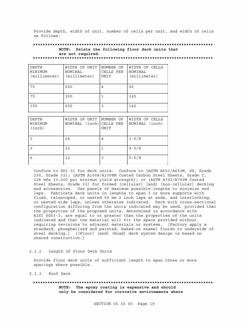
Provide depth, width of unit, number of cells per unit, and width of cells as follows:
**************************************************************************NOTE: Delete the following floor deck units that are not required.
**************************************************************************
DEPTH MINIMUM (millimeter)
WIDTH OF UNIT NOMINAL (millimeter)
NUMBER OF CELLS PER UNIT
WIDTH OF CELLS NOMINAL (millimeter)
75 600 4 92
75 300 1 245
150 600 3 142
DEPTH MINIMUM (inch)
WIDTH OF UNIT NOMINAL (inch)
NUMBER OF CELLS PER UNIT
WIDTH OF CELLS NOMINAL (inch)
3 24 4 3-5/8
3 12 1 9-5/8
6 12 3 5-5/8
Conform to SDI 31 for deck units. Conform to [ASTM A653/A653M, SS, Grade 230, Grade 33]; [ASTM A1008/A1008M Coated Carbon Steel Sheets, Grade C, 228 mPa 33,000 psi minimum yield strength]; or [ASTM A792/A792M Coated Steel Sheets, Grade 33] for formed [cellular] [and] [non-cellular] decking and accessories. Use panels of maximum possible lengths to minimize end laps. Fabricate deck units in lengths to span 3 or more supports with flush, telescoped, or nested 50 mm 2 inch laps at ends, and interlocking, or nested side laps, unless otherwise indicated. Deck with cross-sectional configuration differing from the units indicated may be used, provided that the properties of the proposed units, determined in accordance with AISI SG03-3, are equal to or greater than the properties of the units indicated and that the material will fit the space provided without requiring revisions to adjacent materials or systems. [Factory apply a standard, phosphatized and painted, baked-on enamel finish to underside of steel decking.] [[Floor] [and] [Road] deck system design is based on shared construction.]
2.3.2 Length of Floor Deck Units
Provide floor deck units of sufficient length to span three or more spacings where possible.
2.3.3 Roof Deck
**************************************************************************NOTE: The epoxy coating is expensive and should only be considered for corrosive environments where
SECTION 05 30 00 Page 19

justified by a cost analysis.**************************************************************************
Conform to ASTM A792/A792M or ASTM A1008/A1008M for deck used in conjunction with insulation and built-up roofing. Fabricate roof deck units of [[0.75] [_____] mm [0.0295] [_____] inch design thickness or thicker steel] [the steel design thickness required by the design drawings] and [shop painted] [galvanized] [painted with an epoxy coating or equivalent applied to prime-coating in accordance with manufacturer's standard] [zinc-coated in conformance with ASTM A653/A653M, G90 coating class or aluminum-zinc coated in accordance with ASTM A792/A792M Coating Designation AZ55].
2.3.3.1 Cant Strips for Roof Decks
**************************************************************************NOTE: When cant strips exceeding the dimensions specified in the following paragraph are required, the steel sheet quality and thickness must be revised as required.
**************************************************************************
Fabricate cant strips from the specified commercial-quality steel sheets not less than nominal 0.91 millimeter 0.0359 inch thick before galvanizing. Bend strips to form a 45-degree cant not less than 125 millimeter 5 inch wide, with top and bottom flanges a minimum 75 millimeter 3 inch wide. Length of strips 3000 millimeter 10 feet.
2.3.3.2 Ridge and Valley Plates for Roof Decks
Fabricate plates from the specified structural-quality steel sheets, not less than nominal 0.91 millimeter 0.0359 inch thick before galvanizing. Provide plates of minimum 120 millimeter 4-1/2 inch wide and bent to provide tight fitting closures at ridges and valleys. Provide a minimum length of ridge and valley plates of 3000 millimeter 10 feet.
2.3.3.3 Metal Closure Stripsfor Roof Decks
Fabricate strips from the specified commercial-quality steel sheets not less than nominal 0.91 millimeter 0.0359 inch thick before galvanizing. Provide strips from the configuration required to provide tight-fitting closures at open ends and sides of steel roof decking.
2.3.4 Form Deck
Conform to ASTM A653/A653M or ASTM A1008/A1008M for deck used as formwork for concrete. Fabricate form deck of[ [0.38] [_____] mm [0.015] [_____] inch design thickness or thicker steel.] [the steel design thickness required by the design drawings.] [Paint with one coat of manufacture's standard paint.] [Zinc-coat in conformance with ASTM A653/A653M,[ G60][ G90] coating class.]
2.3.5 Composite Deck
[ Conform to ASTM A653/A653M or ASTM A1008/A1008M for composite deck assembly. Fabricate deck used as the tension reinforcing in composite deck if [0.75][_____] mm [0.0295] [_____] inch design thickness or thicker steel.] [The steel design thickness required by the design drawings. Zinc-coat in conformance with ASTM A653/A653M, [G60][G90] coating class.
SECTION 05 30 00 Page 20

In addition to resisting shear, provide devices to resist vertical separation between the steel deck and the concrete. Provide one of the following types of shear devices:
a. Mechanically fixed shear devices such as embossments, holes, or welded buttons.
b. Mechanically or powder-actuated devices such as inverted, triangular or L-shaped ribs
]2.3.6 [Acoustical Steel Deck
**************************************************************************NOTE: A noise reduction coefficient of 0.70 is a commonly used coefficient. The coefficient can also be obtained from manufacturer's literature. However, specific design requirements must be considered and the appropriate value inserted. The manufacturer's standard acoustical steel deck shall be provided where indicated.
**************************************************************************
Provide a Noise Reduction Coefficient (NRC) rating of not less than [0.70] [_____], when tested in accordance with ASTM C423, Standard Mounting No. 6. Provide sound absorbing materials with either [glass fiber in roll or premolded form for acoustical steel deck (noncellular)] [and] [or] [glass fiber rigid strip for acoustical steel deck (cellular)] in accordance with manufacturer's standards.
]2.3.7 [Venting
**************************************************************************NOTE: Include this paragraph on projects where lightweight insulating concrete roof systems are used. Verify that deck size specified is available as vented.
**************************************************************************
To ensure positive venting from the underside, provide slotted or perforated steel deck to receive concrete fill, overlay, or a poured concrete deck.
]2.3.8 [Shop Priming
**************************************************************************NOTE: Specify shop priming when decking will receive field applied finish painted. Paint will not adhere to passivating or stabilizing treatment commonly used on galvanized steel surfaces to prevent "white rust." Coordinate requirements for finishes with requirements for fireproofing and field finish painting.
**************************************************************************
Shop prime accessories and [underside of] deck at the factory after coating. Clean surfaces in accordance with the manufacturer's standard procedure followed by a spray, dip or roller coat of rust-inhibitive primer, oven cured.
SECTION 05 30 00 Page 21

]2.3.9 Touch-Up Paint
Provide touch-up paint for shop-painted units [of the same type used for the shop painting] [_____], and touch-up paint for zinc-coated units of [an approved galvanizing repair paint with a high-zinc dust content] [_____]. Touch-up welds with paint conforming to SSPC Paint 20 in accordance with ASTM A780/A780M. Maintain finish of deck units and accessories by using touch-up paint whenever necessary to prevent the formation of rust.
For floor decking installation, wire brush, clean, and touchup paint the scarred areas on the top and bottom surfaces of the metal floor decking and on the surface of supporting steel members. Include welds, weld scars, bruises, and rust spots for scarred areas. Touched up the galvanized surfaces with galvanizing repair paint. Touch up the painted surfaces with paint for the repair of painted surfaces.
After roof decking installation, wire brush, clean, and touchup paint the scarred areas on top and bottom surfaces of metal roof decking. The scarred areas include welds, weld scars, bruises, and rust spots. Touchup galvanized surfaces with galvanizing repair paint. Touchup painted surfaces with repair paint of painted surfaces.
PART 3 EXECUTION
3.1 EXAMINATION
Prior to installation of decking units and accessories, examine worksite to verify that as-built structure will permit installation of decking system without modification.
3.2 INSTALLATION
**************************************************************************NOTE: Use SDI Pub No. 30 for all decks except those designed for diaphragm action. Use SDI DDM 03 with Appendix VI and Errata or ICC-ES Evaluation Service Reports (ESR) based on Acceptance Criteria (AC) 43 diaphragm testing. Indicate cellular deck to be used as wiring raceways on the project drawings if included below.
NOTE: The designer must determine if there are shoring requirements for composite decks. For most applications the design is selected so that shoring is not required. Shoring requirements shall be detailed on the design drawings.
**************************************************************************
Install steel deck units in accordance with [SDI 31][SDI DDMO3 and] approved shop drawings. Place units on structural supports, properly adjusted, leveled, and aligned at right angles to supports before permanently securing in place. Damaged deck and accessories including material which is permanently stained or contaminated, deformed, or with burned holes shall not be installed. Extend deck units over three or more supports unless absolutely impractical. Report inaccuracies in alignment or leveling to the Contracting Officer and make necessary corrections before permanently anchoring deck units. Locate deck ends over supports only. [Ends of floor deck may be lapped or butted.] Do not use unanchored
SECTION 05 30 00 Page 22

deck units as a work or storage platform. [Do not fill unanchored deck with concrete.] Permanently anchor units placed by the end of each working day. Do not support suspended ceilings, light fixtures, ducts, utilities, or other loads by steel deck unless indicated. Distribute loads by appropriate means to prevent damage. Prepare [shoring in position before concrete placement begins in composite or form deck. ][Size cellular decking provided as electrical raceways to accommodate indicated wiring systems. Chip off burrs and eliminate sharp edges which may damage wiring. Mesh decking panels accurately and place in accordance with UL 209.] Neatly fit [acoustical material into the rib voids.]
3.2.1 Attachment
**************************************************************************NOTE: Refer to UFC 1-200-01 for shear capacity, flexibility, connection details, size and spacing of welds and attachments, and concrete fill requirements.
For diaphragm acting decks, refer to Steel Deck Institute's SDI DDMO3, "Diaphragm Design Manual".
Where welding only is allowed, delete the first two bracketed phrases and include the last bracketed phrase.
**************************************************************************
Immediately after placement and alignment, and after correcting inaccuracies, permanently fasten steel deck units to structural supports and to adjacent deck units by welding with normal 16 mm 5/8 inch diameter puddle welds [or fastened with screws, powder-actuated fasteners, or pneumatically driven fasteners] as indicated on the design drawings and in accordance with manufacturer's recommended procedure[ and SDI 31]. Clamp or weight deck units to provide firm contact between deck units and structural supports while performing welding [or fastening]. [Anchoring the deck to structural supports with powder-actuated fasteners or pneumatically driven fasteners is prohibited.] Attachment of adjacent deck units by button-punching is prohibited.
**************************************************************************The fasteners shall provide minimum required pull-out, pull-over and shear resistance based upon test results of the specific steel deck and fastener as listed in the current edition of the Factory Mutual Approval Guide and Factory Mutual Data Sheet 1-28 or manufacturer's data sheets. If studs are being welded to the top flanges of beams, the deck ends should be butted. If not, deck ends should be lapped. Welding washers shall be used at welded connections when deck thickness is less than 0.711 mm 0.028 inch. Fasteners for roof insulations are specified in Section 07 22 00 ROOF AND DECK INSULATION.
**************************************************************************
3.2.1.1 Welding
**************************************************************************NOTE: Show location, size, and spacing of
SECTION 05 30 00 Page 23

attachments on the drawings for composite and diaphragm-acting decks. If they are not shown, delete the first phrase and include the second. Coordinate finish repair with finish requirements.
**************************************************************************
Perform welding in accordance with AWS D1.3/D1.3M using methods and electrodes recommended by the manufacturers of the base metal alloys being used. Ensure only operators previously qualified by tests prescribed in AWS D1.1/D1.1M and AWS D1.3/D1.3M make welds. Immediately recertify, or replace qualified welders, that are producing unsatisfactory welding. [Indicate] [Conform to the recommendations of the Steel Deck Institute and the steel deck manufacturer]for location, size, and spacing of fastening. [Do] [Do not] use welding washers at the connections of the deck to supports. Do not use welding washers at sidelaps. Holes and similar defects will not be acceptable. [Lap 50 mm 2 inch] [butted] deck ends. Attach all partial or segments of deck units to structural supports in accordance with Section 2.5 of SDI DDMO3. Attach [shear connectors as shown and welded as per AWS D1.1/D1.1M [through the steel deck to the steel member] [directly to the steel member]]. Immediately clean welds by chipping and wire brushing. Heavily coat welds, cut edges and damaged portions of [coated finish with zinc-dust paint conforming to ASTM A780/A780M] [shop [primed] [painted] finish with the manufacturer's standard touch-up paint].
3.2.1.2 [Fastening
**************************************************************************NOTE: Delete this paragraph when only welding is allowed.
**************************************************************************
Anchor deck to structural supports and adjoining units with mechanical fasteners as listed by the Steel Deck Institute, ICC-ES, the fastener and steel deck manufacturers, and approved by the Contracting Officer. Drive the [powder-actuated fasteners with a low-velocity piston tool by an operator authorized by the manufacturer of the powder-actuated tool. Drive pneumatically fasteners with a low-velocity fastening tool and comply with the manufacturer's recommendations.]
]3.2.1.3 Fastening Floor Deck Units
**************************************************************************NOTE: When fire-resistance-rated construction is required, the fire rating agency's specifications for the applicable floor or roof and ceiling construction must be consulted.
**************************************************************************
Fasten floor deck units to the steel supporting members at ends and at all intermediate supports, both parallel and perpendicular to deck span, by welds. Do not exceed spacing of welds of 300 millimeter 12 inch on center, with a minimum of two welds per floor deck unit at each support. Provide 20 millimeter 3/4 inch minimum diameter fusion welds. Coordinate welding sequence and procedure with the placing of the floor deck units. Blow holes shall be cause for rejection.
Lock sidelaps between adjacent floor deck units together at intervals not exceeding 1220 millimeter 48 inch on center by welding or button punching
SECTION 05 30 00 Page 24

for all spans.
[Free the interior of cells that will be used for electrical raceways of welds having sharp points or edges.]
3.2.2 Openings
**************************************************************************NOTE: Include bracketed phrases when design is based on seismic requirements. When cells of cellular steel floor decking will be used for air ducts, the cutting of decking units for connections to air distribution ductwork, outlets, and system accessories must be coordinated with and specified in applicable sections of the mechanical specifications.
When cells of cellular metal floor decking will be used for electrical raceways, the inspection of these cells, cutting for inserts, and installation of electrical outlets, fittings, or grounding of the metal floor decking, be coordinated with and specified in applicable sections of the electrical specifications.
**************************************************************************
Cut or drill all holes and openings required and be coordinated with the drawings, specifications, and other trades. Frame and reinforce openings through the deck in conformance with SDI DDP. Reinforce [holes and openings 150 to 300 mm 6 to 12 inch across by 1.204 mm 0.0474 inch thick steel sheet at least 300 mm 12 inch wider and longer than the opening and be fastened to the steel deck at each corner of the sheet and at a maximum of 150 mm 6 inch on center. Reinforce holes and openings larger than 300 mm 12 inch by steel channels or angles installed perpendicular to the steel joists and supported by the adjacent steel joists. Install steel channels or angles perpendicular to the deck ribs and fasten to the channels or angles perpendicular to the steel joists. ][Deck manufacturer shall approve holes or openings larger than 150 mm 6 inch in diameter prior to drilling or cutting. ] [Openings must not interfere with seismic members such as chords and drag struts.]
3.2.3 Deck Damage
SDI MOC2, for repair of deck damage.
3.2.4 Accessory Installation
3.2.4.1 Adjusting Plates
Provide in locations too narrow to accommodate full-size deck units and install as shown on shop drawings.
3.2.4.2 End Closures
Provide end closure to close open ends of cells at columns, walls, and openings in deck.
SECTION 05 30 00 Page 25

3.2.4.3 Closures Above Partitions
**************************************************************************NOTE: Coordinate options in paragraphs entitled "Partition Enclosures" and "Closures Above Partitions." When a suspended acoustical ceiling is provided below the metal deck, the closures above partitions may be eliminated for acoustical purposes provided the acoustical properties of the ceiling are adequate to restrict sound transmission to a level consistent with the facility design criteria.
**************************************************************************
Provide for closing voids between cells over partitions that are perpendicular to direction of cells. Provide a one-piece closure strip for partitions 100 mm 4 inch nominal or less in thickness and two-piece closure strips for wider partitions. [Provide sheet metal closures above fire-rated partitions at both sides of partition with space between filled with fiberglass insulation.] [Provide flexible rubber closures above acoustic-rated partitions at both sides of partition with space between filled with blanket insulation.]
3.2.4.4 Cover Plates
[Provide metal cover plates, or joint tape, at joints between cellular decking sheets to be used as electrical raceways.] [Where concrete leakage would be a problem, provide metal cover plates, or joint tape, at joints between decking sheets, cellular or noncellular, to be covered with concrete fill.]
3.2.4.5 [Column Closures
**************************************************************************NOTE: Delete this paragraph if steel floor decks are not included.
**************************************************************************
Provide for spaces between floor decking and columns which penetrate the deck. Field cut closure plate to fit column in the field and tack weld to decking and columns.
]3.2.4.6 Access Hole Covers
Provide access whole covers to seal holes cut in decking to facilitate welding of the deck to structural supports.
3.2.4.7 Hangers
**************************************************************************NOTE: Location, spacing, and size of hanger clips or loops must be indicated or specified, as applicable to the project.
**************************************************************************
Provide as indicated to support [utility system] [and] [suspended ceilings]. Space devices [as indicated] [so as to provide one device per 0.60 square meters 6.25 square feet].
SECTION 05 30 00 Page 26

3.2.5 [Sound Absorbing Material
**************************************************************************NOTE: Include this paragraph when required by the design for acoustical deck.
**************************************************************************
Install sound absorbing [glass fiber roll or premolded form, neatly in voids between perforated webs of acoustical noncellular steel deck] [and] [glass fiber rigid strip, in cells of acoustical cellular steel deck]. Keep sound absorbing material dry before, during and after installation.
]3.2.6 [Concrete Work
**************************************************************************NOTE: Ensure that admixtures containing chloride salts are not used in concrete placed on steel deck. Coordinate with Section 03 30 00 CAST-IN-PLACE CONCRETE. Delete this paragraph if concrete is not cast on metal decking.
**************************************************************************
Prior to placement of concrete, inspect installed decking to ensure that there has been no permanent deflection or other damage to decking. Replace decking which has been damaged or permanently deflected as approved by the Contracting Officer. Place concrete on metal deck in accordance with Construction Practice of SDI 31.
]3.2.7 Preparation of Fire-Proofed Surfaces
Provide deck surfaces, both composite and noncomposite, which are to receive sprayed-on fireproofing, galvanized and free of all grease, mill oil, paraffin, dirt, salt, and other contaminants which impair adhesion of the fireproofing. Complete any required cleaning prior to steel deck installation using a cleaning method that is compatible with the sprayed-on fireproofing.
3.3 ROOF SUMP PANS
Place sump pans over openings in roof decking and fusion welded to top surface of roof decking. Do not exceed spacing of welds of 300 millimeter 12 inch with not less than one weld at each corner. Field cut opening in the bottom of each roof sump pan to receive the roof drain as part of the work of this section.
3.4 CANT STRIPS FOR ROOF DECKS
Provide strips to be fusion welded to surface of roof decking, secured to wood nailers by galvanized screws or to steel framing by galvanized self-tapping screws or welds. Do not exceed spacing of welds and fasteners of 300 millimeter 12 inch. Lap end joints a minimum 75 millimeter 3 inch and secure with galvanized sheet metal screws spaced a maximum 100 millimeter 4 inch on center.
3.5 RIDGE AND VALLEY PLATES FOR ROOF DECKS
Provide plates to be fusion welded to top surface of roof decking. Lap end joints a minimum 75 millimeter 3 inch. For valley plates, provide endlaps to be in the direction of water flow.
SECTION 05 30 00 Page 27

3.6 CLOSURE STRIPS FOR ROOF DECKS
Provide closure strips at open, uncovered ends and edges of the roof decking and in voids between roof decking and top of walls and partitions where indicated. Install closure strips in position in a manner to provide a weathertight installation.
3.7 ROOF INSULATION SUPPORT FOR ROOF DECKS
Provide metal closure strips for support of roof insulation where rib openings in top surface of metal roof decking occur adjacent to edges and openings. Weld metal closure strips in position.
3.8 CLEANING AND PROTECTION FOR ROOF DECKS
Upon completion of the deck, sweep surfaces clean and prepare for installation of the roofing.
3.9 [FIELD QUALITY CONTROL
**************************************************************************NOTE: Include this paragraph when roof decks that are not receiving concrete are in the project. Coordinate paragraph with requirements for roofing membrane.
**************************************************************************
3.9.1 Decks Not Receiving Concrete
Inspect the decking top surface for distortion after installation. For roof decks not receiving concrete, verify distortion by placing a straight edge across three adjacent top flanges. The maximum allowable gap between the straight edge and the top flanges is 2 mm 1/16 inch; when gap is more than 2 mm 1/16 inch, provide corrective measures or replacement. Reinspect decking after performing corrective measures or replacement.
] -- End of Section --
SECTION 05 30 00 Page 28