uganda standards template -...
TRANSCRIPT

UGANDA STANDARD
US ISO 4586-2
First Edition2009-09-04
Reference numberUS ISO 4586-2: 2004
© UNBS 2009
High-pressure decorative laminates — Sheets made from thermosetting resins — Part 2: Determination of properties

US ISO 4586-2: 2004
© UNBS 2009 – All rights reserved ii
Compliance with this standard does not, of itself confer immunity from legal obligations
A Uganda Standard does not purport to include all necessary provisions of a contract. Users are responsible for its correct application
© UNBS 2009
All rights reserved. Unless otherwise specified, no part of this publication may be reproduced or utilised in any form or by any means, electronic or mechanical, including photocopying and microfilm, without prior written permission from UNBS.
Requests for permission to reproduce this document should be addressed to
The Executive Director Uganda National Bureau of Standards P.O. Box 6329 Kampala Uganda Tel: 256 41 505 995 Fax: 256 41 286 123 E-mail: [email protected]: www.unbs.go.ug

US ISO 4586-2: 2004
© UNBS 2009 - All rights reserved iii
National foreword
Uganda National Bureau of Standards (UNBS) is a parastatal under the Ministry of Tourism, Trade and Industry established under Cap 327, of the Laws of Uganda. UNBS is mandated to co-ordinate the elaboration of standards and is (a) a member of International Organisation for Standardisation (ISO) and
(b) a contact point for the WHO/FAO Codex Alimentarius Commission on Food Standards, and
(c) the National Enquiry Point on TBT/SPS Agreements of the World Trade Organisation (WTO).
The work of preparing Uganda Standards is carried out through Technical Committees. A Technical Committee is established to deliberate on standards in a given field or area and consists of representatives of consumers, traders, academicians, manufacturers, government and other stakeholders.
Draft Uganda Standards adopted by the Technical Committee are widely circulated to stakeholders and the general public for comments. The committee reviews the comments before recommending the draft standards for approval and declaration as Uganda Standards by the National Standards Council. This Uganda Standard, US ISO 4586-2:2004, High-pressure decorative laminates — Sheets made from thermosetting resins — Part 2: Determination of properties, is identical with and has been reproduced from a International Standard, ISO 4586-2:2004, High-pressure decorative laminates — Sheets made from thermosetting resins — Part 2: Determination of properties, and adopted as a Uganda Standard.
This standard was developed by the Furniture Standards Technical Committee (UNBS/TC 12).
Wherever the words, "International Standard" appear, they should be replaced by "Uganda Standard."

INTERNATIONALSTANDARD
ISO4586-2
Fifth edition2004-10-15
Reference numberISO 4586-2:2004(E)
© ISO 2004
High-pressure decorative laminates — Sheets made from thermosetting resins —
Part 2:Determination of properties
Stratifiés décoratifs haute pression — Plaques à base de résines thermodurcissables —
Partie 2: Détermination des caractéristiques

ISO 4586-2:2004(E)
ii © ISO 2004 – All rights reserved
PDF disclaimer
This PDF file may contain embedded typefaces. In accordance with Adobe's licensing policy, this file may be printed or viewed but shallnot be edited unless the typefaces which are embedded are licensed to and installed on the computer performing the editing. Indownloading this file, parties accept therein the responsibility of not infringing Adobe's licensing policy. The ISO Central Secretariataccepts no liability in this area.
Adobe is a trademark of Adobe Systems Incorporated.
Details of the software products used to create this PDF file can be found in the General Info relative to the file; the PDF-creationparameters were optimized for printing. Every care has been taken to ensure that the file is suitable for use by ISO member bodies. In theunlikely event that a problem relating to it is found, please inform the Central Secretariat at the address given below.
© ISO 2004
All rights reserved. Unless otherwise specified, no part of this publication may be reproduced or utilized in any form or by any means,electronic or mechanical, including photocopying and microfilm, without permission in writing from either ISO at the address below orISO's member body in the country of the requester.
ISO copyright officeCase postale 56 • CH-1211 Geneva 20Tel. + 41 22 749 01 11Fax + 41 22 749 09 47E-mail [email protected] www.iso.org
Published in Switzerland

ISO 4586-2:2004(E)
© ISO 2004 – All rights reserved iii
Contents Page
1 Scope .................................................................................................................................................... 1
2 Normative references .......................................................................................................................... 1
3 Terms and definitions .......................................................................................................................... 2
4 Thickness ............................................................................................................................................. 2
5 Appearance .......................................................................................................................................... 2
6 Resistance to surface wear ................................................................................................................ 4
7 Resistance to immersion in boiling water ......................................................................................... 7
8 Resistance to dry heat ........................................................................................................................ 9
9 Resistance to wet heat ...................................................................................................................... 10
10 Resistance to steam .......................................................................................................................... 12
11 Dimensional stability ......................................................................................................................... 14
12 Resistance to impact by small-diameter ball .................................................................................. 19
13 Resistance to impact by large-diameter ball ................................................................................... 23
14 Resistance to cracking under stress (thin laminates ) ................................................................... 26
15 Resistance to scratching .................................................................................................................. 30
16 Resistance to staining ....................................................................................................................... 36
17 Lightfastness ..................................................................................................................................... 43
18 Resistance to cigarette burns ........................................................................................................... 48
19 Formability ......................................................................................................................................... 57
20 Resistance to blistering .................................................................................................................... 64
21 Resistance to crazing of compact laminates .................................................................................. 68
22 Resistance to moisture of double-faced compact laminates ........................................................ 69
Bibliography ............................................................................................................................................... 71

ISO 4586-2:2004(E)
iv © ISO 2004 – All rights reserved
Foreword
ISO (the International Organization for Standardization) is a worldwide federation of national standards bodies(ISO member bodies). The work of preparing International Standards is normally carried out through ISOtechnical committees. Each member body interested in a subject for which a technical committee has beenestablished has the right to be represented on that committee. International organizations, governmental andnon-governmental, in liaison with ISO, also take part in the work. ISO collaborates closely with the InternationalElectrotechnical Commission (IEC) on all matters of electrotechnical standardization.
International Standards are drafted in accordance with the rules given in the ISO/IEC Directives, Part 2.
The main task of technical committees is to prepare International Standards. Draft International Standardsadopted by the technical committees are circulated to the member bodies for voting. Publication as anInternational Standard requires approval by at least 75 % of the member bodies casting a vote.
Attention is drawn to the possibility that some of the elements of this document may be the subject of patentrights. ISO shall not be held responsible for identifying any or all such patent rights.
ISO 4586-2 was prepared by Technical Committee ISO/TC 61, Plastics, Subcommittee SC 11, Products.
This fifth edition cancels and replaces the fourth edition (ISO 4586-2:1997), of which it constitues a minorrevision intended
a) to combine the 1997 edition with its amendments (Amendments 3 to 8) to give a single document;
b) to reintroduce a previously deleted method (determination of resistance to colour change in light from anenclosed carbon-arc lamp) (see 17.3).
ISO 4586 consists of the following parts, under the general title High-pressure decorative laminates — Sheetsmade from thermosetting resins :
— Part 1: Classification and specifications
— Part 2: Determination of properties

INTERNATIONAL STANDARD ISO 4586-2:2004(E)
© ISO 2004 – All rights reserved 1
High-pressure decorative laminates — Sheets made from thermosetting resins —
Part 2:Determination of properties
1 Scope
This part of ISO 4586 specifies methods of test for determination of the properties of high-pressure decorativelaminated sheets as defined in Clause 3. These methods are primarily intended for testing the sheets specifiedin ISO 4586-1.
The precision of the test methods specified in Clauses 4, 7 and 11 of this part of ISO 4586 is not knownbecause inter-laboratory data are not available. When inter-laboratory data are obtained, precision statementswill be added to the test methods at the following revision. As all the other test methods have an end pointdetermination based on subjective judgement, it is not meaningful to make a statement of precision in thesecases.
2 Normative references
The following referenced documents are indispensable for the application of this document. For datedreferences, only the edition cited applies. For undated references, the latest edition of the referenced document(including any amendments) applies.
ISO 105-A02, Textiles — Tests for colour fastness — Part A02: Grey scale for assessing change in colour
ISO 105-B02, Textiles — Tests for colour fastness — Part B02: Colour fastness to artificial light: Xenon arcfading lamp test
ISO 4211-3, Furniture — Tests for surface finishes — Part 3: Assessment of resistance to dry heat
ISO 4586-1:2004, High-pressure decorative laminates — Sheets made from thermosetting resins — Part 1:Classification and specification
ISO 4892:1981, Plastics — Methods of exposure to laboratory light sources1)
ISO 4892-1, Plastics — Methods of exposure to laboratory light sources — Part 1: General guidance
ISO 4892-2:1994, Plastics — Methods of exposure to laboratory light sources — Part 2: Xenon-arc sources
ISO 6506-1, Metallic materials — Brinell hardness test — Part 1: Test method
ISO 9352, Plastics — Determination of resistance to wear by abrasive wheels
ISO 9370, Plastics — Instrumental determination of radiant exposure in weathering tests — General guidanceand basic test method
CIE Publication No. 85:1989, Solar spectral irradiance
1) Withdrawn, but still used in certain Asian countries.

ISO 4586-2:2004(E)
2 © ISO 2004 – All rights reserved
3 Terms and definitions
For the purposes of this document, the definition of high-pressure decorative laminate(s) given in 3.1 ofISO 4586-1:2004 applies.
The abbreviation “HPDL” for high-pressure decorative laminate(s) is used in ISO 4586. It should be noted thatthe abbreviation “HPL” is frequently used instead of “HPDL”, and the term “HPL” in the European standardEN 438 is equivalent to “HPDL” in ISO 4586.
4 Thickness
4.1 Principle
The thickness of a sheet is measured using a micrometer or a dial gauge indicator.
4.2 Apparatus
4.2.1 Thickness gauge (ratchet-type micrometer or dial gauge indicator), having two flat parallel measuringsurfaces of diameter at least and capable of being read to . When the thickness of a decorativelaminated sheet is being measured, the two surfaces shall exert a pressure of to upon eachother.
4.3 Test specimen
The specimen shall be the sheet under test, as received.
4.4 Procedure
Check the gauge for accuracy and then determine the thickness of the sheet to the nearest . It isrecommended that the thickness be measured at a minimum of four points and at a distance of at least from the edge of the sheet.
4.5 Test report
The test report shall include the following information:
a) a reference to this part of ISO 4586;
b) the name and type of product;
c) all values measured;
d) the location of the points at which measurements were made;
e) any deviation from the specified test method;
f) the date of the test.
5 Appearance
5.1 Surface defects
5.1.1 Principle
Sheets are inspected for surface appearance under standardized conditions of lighting and viewing.
6 mm 0,01 mm10 kPa 100 kPa
0,02 mm20 mm

ISO 4586-2:2004(E)
© ISO 2004 – All rights reserved 3
5.1.2 Apparatus
5.1.2.1 Horizontal inspection table, of height approximately and large enough to accommodate thelargest sheets to be inspected.
5.1.2.2 Overhead white fluorescent lights, of colour temperature approximately and giving anintensity of to over the whole area of the largest sheets to be inspected. A convenient distance ofthe lights from the inspection table is approximately .
5.1.3 Test specimen
The specimen shall be the sheet under test, as received.
5.1.4 Procedure
Place the sheet, decorative face uppermost, on the inspection table. Wipe it free of any loose contamination, ifnecessary, with a soft cloth. Inspect it from the distance required by ISO 4586-1:2004 for defects such assmudges, smears, fingerprints, scratches, foreign particles, damage or any other form of blemish evident withinthe decorative surface.
The inspector shall use normal vision, corrected if necessary. No magnifying glass shall be used in viewing thesheet.
5.1.5 Test report
The test report shall include the following information:
a) a reference to this part of ISO 4586;
b) the name and type of product;
c) the viewing distance and any defects observed;
d) any deviation from the specified test method;
e) the date of the test.
5.2 Flatness
5.2.1 Apparatus
5.2.1.1 Straightedge, of length, with optional dial gauge (see Figure 1).
5.2.2 Test specimen
The specimen shall be the sheet under test, as received, stored in the conditions recommended by themanufacturer.
5.2.3 Procedure
Place the sheet under test, concave side up, on a flat surface. Measure the departure between the straightedgeand the concave surface of the laminate at the point of maximum curvature.
700 mm
5 000 K800 lx 1 000 lx
1,5 m
1 000 mm

ISO 4586-2:2004(E)
4 © ISO 2004 – All rights reserved
5.2.4 Test report
The test report shall include the following information:
a) a reference to this part of ISO 4586;
b) the name and type of product;
c) the maximum deviation, in millimetres;
d) any deviation from the specified test method;
e) the date of the test.
6 Resistance to surface wear
6.1 Principle
The test measures the ability of the decorative surface of the sheet under test to resist abrasive wear-through tothe sub-layer. Abrasion is achieved by rotating a specimen in contact with a pair of loaded cylindrical wheelscovered with abrasive paper. The wheels are positioned so that their cylindrical faces are equidistant from thespecimen's axis of rotation but not tangential to it. As they are turned by the rotating specimen, they abrade anannular track on the specimen's surface. The numbers of revolutions of the specimen required to cause defineddegrees of abrasion are used as measures of resistance to surface wear.
6.2 Materials
6.2.1 Calibration plates of rolled zinc sheet (Taber S-34 or equivalent), having a thickness of and a Brinell hardness of when tested in accordance with ISO 6506-1, except that
the ball diameter shall be and the load .
Key
1 dial gauge
2 straightedge
3 laminate
4 flat surface
distance between the straightedge and the surface of the laminate
Figure 1 — Example of equipment for measuring flatness (see 5.2.1)
h
0,8 mm± 0,1 mm 48± 25 mm 360 N

ISO 4586-2:2004(E)
© ISO 2004 – All rights reserved 5
6.2.2 Abrasive paper strips (Taber S-42 or equivalent), of width and length about, having the following composition:
a) paper of grammage to ;
b) open coated 180 grit powdered aluminium oxide (Al2O3) having a particle size such that it will pass througha sieve of aperture and remain on a sieve having an aperture of ;
c) adhesive backing (optional).
6.2.3 Double-sided adhesive tape, required only if the abrasive paper has no adhesive backing.
6.3 Apparatus
6.3.1 Test machine, as specified in ISO 9352.
NOTE A suitable machine is available from Taber Acquisition Corp., Taber Industries, 455 Bryant St, P.O. Box 164, NorthTonawanda, NY 14120, USA. This is an example of a suitable product available commercially. This information is given forthe convenience of users of this part of ISO 4586 and does not constitute an endorsement by ISO of this product.
6.3.2 Conditioning chamber, with a standard atmosphere of , relative humidity of .
6.4 Test specimens
Each specimen shall be a piece of the sheet under test, shaped to fit the type of clamping device used. It willusually be a disc of diameter about , or a square of side about with its corners rounded to givea diagonal of about , and it will usually have a hole of diameter in its centre. Three specimensshall be prepared.
6.5 Preparation of specimens and abrasive paper
Clean the surface of the specimens with a non-hazardous organic solvent which is immiscible with water. Usinga suitable marker pen, mark the surface of each specimen with two lines at right angles to each other so that thesurface area is divided into quadrants. Precondition the specimens and the abrasive strips for at least inthe conditioning atmosphere (see 6.3.2) before testing. After preconditioning, seal the paper strips in suitablepolyethylene bags (maximum 10 strips per bag) until required for immediate use.
6.6 Procedure
6.6.1 Preparation of abrasive wheels
Bond a strip of preconditioned unused abrasive paper (6.2.2) to each of the rubber-covered wheels, using eitherthe adhesive backing, if present, or the double-sided adhesive tape (6.2.3), in such a way that the cylindricalsurface is completely covered, but without any overlapping of the abrasive paper.
6.6.2 Calibration of abrasive paper
Prepare two abrasive wheels with preconditioned unused strips of abrasive paper from the batch to be used fortesting (see 6.6.1).
Clamp a zinc plate (6.2.1) in the specimen holder, start the suction device, set the revolution-counter to zero,lower the wheels and abrade the zinc plate for 500 revolutions. Wipe the zinc plate clean and weigh to thenearest . Replace the abrasive paper on the wheels with preconditioned unused strips from the samebatch, clamp the same zinc plate in the specimen holder, lower the abrasive wheels and operate the suctiondevice. Abrade the zinc plate for an additional 500 revolutions, then wipe it clean and reweigh it to the nearest
. Its loss in mass shall be .
12,7 mm± 0,1 mm160 mm
70 g/m2 100 g/m2
100 µm 63 µm
23 C± 2 C (50± 5) %
130 mm 120 mm130 mm 6 mm
72 h
1 mg
1 mg 130 mg± 20 mg

ISO 4586-2:2004(E)
6 © ISO 2004 – All rights reserved
Any batch of abrasive paper which causes a loss in mass of the zinc plate outside this permitted range shall notbe used for testing.
6.6.3 Abrasion of specimen
Perform the test immediately after removal of the specimen and calibrated abrasive paper from thepreconditioning atmosphere.
Prepare two wheels with preconditioned unused abrasive paper from the same batch previously approved bycalibration. Fit the wheels to the machine and set the revolution counter to zero.
Clamp the specimen in the holder, ensuring that its surface is flat. Lower the abrasive wheels on to thespecimen, start the suction device and begin abrading the specimen. Examine the specimen for wear after each25 revolutions and examine the abrasive paper for clogging with abraded particles. Replace the abrasive paperif it becomes clogged, or after 500 revolutions, whichever happens first.
Continue the test in this way until the initial wear point (IP) is reached. Record the number of revolutions andresume the test until the final wear point (FP) is reached. Record the number of revolutions again.
The initial wear point (IP) is the point at which the first clearly recognizable wear-through of the print, pattern,plain colour coating or solid paper appears and the sub-layer becomes exposed in three quadrants, with areasof at least wear-though in each of the three quadrants. The sub-layer for printed patterns is thebackground on which the pattern is printed; for plain colours, it is the first sub-layer of different colour.2) 3)
The final wear point (FP) occurs in the case of a patterned laminate when about of the pattern is removedin the abraded area, and in the case of a plain-colour laminate when an underlayer of a different colour isexposed over about of the abraded area.
6.7 Expression of results
Calculate the wear resistance, expressed as a number of revolutions, for each specimen using the followingequation:
where
IP is the initial wear point, expressed as a number of revolutions;
FP is the final wear point, expressed as a number of revolutions.
Average the value of the initial wear point (IP) of three specimens tested.
Average the value of the wear resistance of three specimens tested, rounded to the nearest 50 revolutions.
2) A full-colour photographic visual aid, known as the IP poster, is available to assist correct interpretation, and increaserepeatability and reproducibility in the determination of the initial wear point (IP). The poster is available from SIS Förlag AB,SE-11880 Stockholm, Sweden; Tel. +46 8 555 523 10, Fax. +46 8 555 523 11 (order reference 21990 IP1 poster).
3) Also available is a dirt size estimation chart. The use of this chart is recommended to determine precisely the size, insquare millimetres, of the wear-through area. It is available from TAPPI, Technology Park/Atlanta, P.O. Box 105113, Atlanta,GA 30348-5113, USA; Tel. +1 770 446 1400, Fax. +1 770 446 6947 (order reference TAPPI — Dirt size estimation chart).
These are examples of suitable products available commercially. This information is given for the convenience of users ofthis part of ISO 4586 and does not constitute an endorsement by ISO of these products.
0,6 mm2
95 %
95 %
Wear resistance =IP + FP
2

ISO 4586-2:2004(E)
© ISO 2004 – All rights reserved 7
6.8 Test report
The test report shall include the following information:
a) a reference to this part of ISO 4586;
b) the name and type of product;
c) the average initial wear point (IP) of the sample under test, in revolutions;
d) the average surface wear resistance of the sample under test, in revolutions;
e) any deviation from the specified procedure;
f) the date of the test.
7 Resistance to immersion in boiling water
7.1 Principle
The effect of immersion in boiling water for is determined by the increase in mass and thickness of testspecimens and by noting the occurrence of any blistering or delamination.
The test is generally in accordance with ISO 62:1999, Method 2, except for a longer period of immersion in theboiling water and the requirement for thickness measurements.
7.2 Apparatus
7.2.1 Balance, accurate to .
7.2.2 Oven, capable of being maintained at .
7.2.3 Vessel, containing boiling distilled water.
7.2.4 Vessel, containing distilled water at .
7.2.5 Desiccator.
7.2.6 Micrometer thickness gauge, as described in 4.2.1.
If curvature of the specimen prevents accurate thickness measurement, then a suitable ball-ended micrometerthickness gauge shall be used.
7.2.7 Suitable heating apparatus (for example an electric hotplate).
7.2.8 Specimen holder, to hold specimens vertically during immersion and prevent contact with otherspecimens or the vessel.
7.3 Test specimens
Three specimens shall be taken from the same sheet. Each specimen shall be square, shallhave the same thickness as the sheet, and shall be cut in such a way that no appreciable heat is generated andthe edges are free from cracks. Cut edges shall be smooth.
7.4 Procedure
Dry the three specimens for in the oven (7.2.2), maintained at , and allow to cool in thedesiccator (7.2.5) to . Weigh each specimen to the nearest (mass ).
2 h
1 mg
50 C± 2 C
23 C± 2 C
50 mm± 1 mm
24 h± 1 h 50 C± 2 C23 C± 2 C 1 mg m1

ISO 4586-2:2004(E)
8 © ISO 2004 – All rights reserved
Measure the thickness of each specimen as specified in Clause 4, but at the centres of its four edges ( , ,, ) and with the external edge of the micrometer anvil approximately from each edge. Mark the
measuring points so that subsequent measurements can be made in the same places.
Place the specimens in the vessel of boiling distilled water (7.2.3). Take care to prevent the specimens frommaking contact over any substantial area with one another or with the vessel.
After , remove the specimens from the boiling water and allow to cool for in thevessel of distilled water maintained at (7.2.4). Take them from the water and remove all surfacewater with a clean dry cloth or with filter paper. Weigh the specimens again to the nearest (mass )within of taking them from the water.
Determine the thickness of each specimen to the nearest at the same points as before ( , , , ).
Examine each specimen visually for change in appearance.
7.5 Expression of results
The boiling water absorbed by each specimen is given, as a percentage by mass, by the formula
where
is the mass of the specimen before immersion;
is the mass of the specimen after immersion.
The percentage increase in thickness at the measuring points of each specimen is given by the formulae
etc.,
where
, , and are the thicknesses measured before immersion;
, , and are the thicknesses measured after immersion.
The percentage by mass of boiling water absorbed by the sample under test shall be the average of the valuesobtained on the three specimens.
The percentage increase in thickness of the sample under test shall be the average of the twelve valuesobtained at the four measuring points on all three specimens.
7.6 Test report
The test report shall include the following information:
a) a reference to this part of ISO 4586;
b) the name and type of product;
d1 d2d3 d4 5 mm
2 h± 5 min 15 min± 5 min23 C± 2 C
1 mg m21 min
0,01 mm d5 d6 d7 d8
m2 −m1
m1× 100
m1
m2
d5 − d1
d1× 100
d6 − d2
d2× 100,
d1 d2 d3 d4
d5 d6 d7 d8

ISO 4586-2:2004(E)
© ISO 2004 – All rights reserved 9
c) the average percentage increase in mass of the three specimens;
d) the average percentage increase in thickness of the three specimens;
e) the effect on the surface of the specimens, expressed in accordance with the following rating scale:
Rating 5: No visible change
Rating 4: Slight change of gloss and/or colour, only visible at certain viewing angles
Rating 3: Moderate change of gloss and/or colour
Rating 2: Marked change of gloss and/or colour
Rating 1: Blistering and/or delamination
f) any deviation from the specified test method;
g) the date of the test.
8 Resistance to dry heat
8.1 Principle
A specimen taken from the sheet under test, bonded to wood chipboard to simulate service conditions, issubjected to dry heat by contact with a vessel of defined heat capacity, initially at but cooling during the
of contact. Resistance to the test conditions is assessed by visual examination.
The test is intended to determine the suitability of decorative laminated sheets for use in kitchens where contactwith moderately hot cooking utensils is to be expected.
8.2 Materials
8.2.1 Glycerol tristearate, or any other material of similar specific heat which will produce the same result. Tominimize health and safety risks, metal blocks can be used if it can be shown that similar results will beobtained. The aluminium alloy block specified in ISO 4211-3 has been found to be suitable.
The same glycerol tristearate or other material may normally be used for at least twenty tests, but if it has beenheated to a temperature above , or in case of dispute, fresh material shall be used.
8.2.2 Fine-faced wood chipboard, square, to nominal thickness with atolerance of , density to and moisture content .
8.2.3 Urea-formaldehyde adhesive, containing approximately filler, or an equivalent adhesive.
8.3 Apparatus
8.3.1 Cast cylindrical aluminium or aluminium alloy vessel, without a lid, the bottom of which has beenmachined flat. It shall have an external diameter of and an overall height of
. The wall thickness shall be and the base thickness .
8.3.2 Heat source, for heating the vessel (8.3.1) uniformly.
8.3.3 Suitable inorganic heat-insulating board, of thickness about and square.
8.3.4 Thermometer, range to .
8.3.5 Fixed frame, to hold the specimen flat.
8.3.6 Stirrer.
180 C20 min
200 C
230 mm± 5 mm 18 mm 20 mm± 0,3 mm 625 kg/m3 700 kg/m3 (9± 2) %
15 %
100 mm± 1,5 mm70 mm± 1,5 mm 2,5 mm± 0,5 mm 2,5+0,5
0 mm
2,5 mm 150 mm
−5 C +250 C

ISO 4586-2:2004(E)
10 © ISO 2004 – All rights reserved
8.4 Test specimen
The specimen shall be prepared by uniformly bonding a piece of the sheet under test to the wood chipboard(8.2.2), using the specified adhesive (8.2.3). One specimen square shall be used. The bondedspecimen shall be preconditioned for at least 7 days at and relative humidity beforebeing used for the test.
For materials of thickness greater than , the effect of bonding the specimen is insignificant and the testmay be conducted with the specimen resting in close contact with the chipboard. This technique is alsoacceptable for routine quality control testing of laminates less than thick. However, in cases of dispute,laminates less than thick shall be bonded to chipboard.
8.5 Procedure
Fill the vessel (8.3.1) with sufficient glycerol tristearate (8.2.1) so that at the level is about fromthe top. Fix the thermometer (8.3.4) centrally in the vessel with its bulb about from the bottom. Raise thetemperature of the glycerol tristearate to approximately , stirring from time to time. Transfer the vessel tothe heat-insulating board (8.3.3) and allow the temperature to fall to , stirring continuously.
Immediately place the vessel on the surface of the specimen and allow to stand for without furtherstirring.
At the end of this period, remove the vessel and allow the specimen to cool for a period of . Examine thespecimen for surface disturbance, for example blistering, crazing, discolouration or loss in gloss visible to thenaked eye, corrected if necessary, allowing the light to fall on the specimen at various angles of incidence.
8.6 Test report
The test report shall include the following information:
a) a reference to this part of ISO 4586;
b) the name and type of product;
c) the effect on the surface of the specimen, expressed in accordance with the following rating scale:
Rating 5: No visible change
Rating 4: Slight change of gloss and/or colour, only visible at certain viewing angles
Rating 3: Moderate change of gloss and/or colour
Rating 2: Marked change of gloss and/or colour
Rating 1: Surface damage and/or blistering
d) any deviation from the specified test method;
e) the date of the test.
9 Resistance to wet heat
9.1 Principle
A specimen taken from the laminate under test (bonded to wood chipboard, if necessary, to simulate serviceconditions) is subjected to wet heat by contact for a specified period with a vessel containing hot water placedin a pool of boiling water which has been poured onto the surface of the specimen. Resistance to the testconditions is assessed by visual examination.
230 mm± 5 mm23 C± 2 C (50± 5) %
2 mm
2 mm2 mm
180 C 15 mm6 mm
185 C180 C± 1 C
20 min
45 min

ISO 4586-2:2004(E)
© ISO 2004 – All rights reserved 11
9.2 Materials
9.2.1 Distilled or de-ionized water.
9.2.2 Sheet of fine-faced wood particleboard, square, with a nominal thickness of to ( ), a density of and moisture content of .
9.2.3 Urea-formaldehyde adhesive, containing approximately filler, or an equivalent adhesive.
9.2.4 Supply of clean, soft, white cloth.
9.3 Apparatus
9.3.1 Cylindrical aluminium or aluminium-alloy vessel, without a lid, the bottom of which has beenmachined flat. It shall have an external diameter of and an overall height of .The wall thickness shall be and the base thickness .
9.3.2 Heat source, for heating the vessel (9.3.1) uniformly.
9.4 Test specimen
Prepare one specimen by uniformly bonding a piece square of the laminate under test to theparticleboard (9.2.2), using the specified adhesive (9.2.3) evenly spread at to . Condition thebonded specimen for at least at and relative humidity before the test.
For materials of thickness greater than , the effect of bonding the specimen is insignificant and the testmay be conducted with the specimen resting in close contact with the chipboard. This technique is alsoacceptable for routine quality control testing of laminates less than thick. However, in cases of dispute,laminates less than thick shall be bonded to particleboard.
9.5 Procedure
Fill the vessel (9.3.1) to from the rim with distilled or de-ionized water, and heat it until the water boilsvigorously.
As water boils and evaporates, dissolved minerals are left behind and will adhere to the vessel walls, formingscale which is an effective insulator. Any such scale shall be removed periodically or the accuracy of the testmay be compromised. The use of distilled or de-ionized water will minimize this problem.
Using tongs, or other suitable means, carefully remove the vessel from the hotplate, pour approximately of boiling water onto the horizontal surface of the test specimen and immediately place the vessel containing theremainder of the boiling water on the surface in the pool of water.
Allow the vessel to remain in place for .
At the end of this period, remove the vessel and wipe the surface of the specimen dry, using a clean, soft cloth(9.2.4) to remove any residual contaminants. Allow the specimen to cool for a period of .
Examine the specimen surface for disturbance (for example blistering, crazing, discolouration or loss in gloss)visible to the naked eye, corrected if necessary, allowing the light to fall on the specimen at various angles ofincidence.
(230± 5) mm 18 mm20 mm ± 0,3 mm (680± 20) kg/m3 (10± 3) %
15 %
(100± 1,5) mm (70± 1,5) mm(2,5± 0,5) mm 2,5+0,5
0 mm
(230± 5) mm80 g/m2 120 g/m2
72 h (23± 2) C (50± 5) %
2 mm
2 mm2 mm
12 mm
10 ml
20 min
45 min

ISO 4586-2:2004(E)
12 © ISO 2004 – All rights reserved
9.6 Expression of results
Express the result of the examination in accordance with the following rating scale:
Rating 5: No visible change
Rating 4: Slight change in gloss and/or colour, only visible at certain viewing angles
Rating 3: Moderate change in gloss and/or colour
Rating 2: Marked change in gloss and/or colour
Rating 1: Surface damage and/or blistering
9.7 Test report
The test report shall include the following information:
a) a reference to this part of ISO 4586;
b) the name, type, and nominal thickness of the product;
c) the effect on the specimen, expressed in accordance with 9.6;
d) any deviation from the method specified;
e) the date of the test.
10 Resistance to steam
10.1 Principle
A specimen from the sheet under test is held in place over the neck of a flask containing boiling water, so thatthe decorative surface of the specimen is exposed to the steam. After , the specimen is removed and allowedto recover for in normal ambient conditions before examination for any change in appearance.
10.2 Materials
10.2.1 Wide-necked Erlenmeyer flask, of capacity and mouth diameter .
10.2.2 Specimen holder and heat screen (see Figure 2).
10.2.3 Non-fibrous filter paper.
10.2.4 Hand lens, with magnification.
10.2.5 Electric hotplate, or other suitable heat source.
10.3 Test specimen
One specimen, measuring the thickness of the sheet under test, is required.
10.4 Procedure
Place approximately of water in the flask (10.2.1) and bring it to the boil on the electric hotplate (10.2.5).Place the heat screen (see 10.2.2) in position around the neck of the flask and place the specimen, decorativeface down, centrally over the mouth of the flask and fix it in position by the wire specimen holder (see Figure 2).
The specimen holder shall be heavy enough to prevent the specimen from curling away from the mouth of theflask.
1 h24 h
250 ml 50 mm
×6
100 mm× 100 mm×
200 ml

ISO 4586-2:2004(E)
© ISO 2004 – All rights reserved 13
After the decorative face has been exposed for to the steam from the boiling water, remove the specimenand use the non-fibrous filter paper (10.2.3) to remove excess water from the surface of the specimen.
Allow the specimen to recover for in normal ambient conditions and then examine the central area of thespecimen with the naked eye, corrected if necessary, and under magnification using the hand lens (10.2.4)for any change in appearance.
10.5 Test report
The test report shall include the following information:
a) a reference to this part of ISO 4586;
b) the name and type of product;
c) the effect on the surface of the specimen, expressed in accordance with the following rating scale:
Rating 5: No visible change
Rating 4: Slight change of gloss and/or colour, only visible at certain viewing angles
Rating 3: Moderate change of gloss and/or colour
Rating 2: Marked change of gloss and/or colour
Rating 1: Blistering and/or delamination
Key
1 specimen
2 wire specimen holder
3 heat screen
4 aluminium ring
5 Erlenmeyer flask, wide-necked,
Figure 2 — Apparatus for resistance to steam (see 10.2)
250 ml
1 h
24 h×6

ISO 4586-2:2004(E)
14 © ISO 2004 – All rights reserved
d) any deviation from the specified procedure;
e) the date of the test.
11 Dimensional stability
11.1 Method A — At elevated temperature
11.1.1 Principle
The test measures the lateral dimensional changes of specimens from the laminate under test over an extremerange of relative humidities at elevated temperatures.
11.1.2 Apparatus
11.1.2.1 Circulating-air oven, capable of being maintained at .
11.1.2.2 High-humidity conditioning chamber, with an atmosphere of relative humidity within the range to and at a temperature of .
11.1.2.3 Standard-atmosphere conditioning chamber, with a standard atmosphere of andrelative humidity .
11.1.2.4 Caliper gauge or other suitable means for measuring length, with a measurement range of atleast , graduated to provide a reading accuracy of . Centering points are recommended but arenot essential.
11.1.2.5 Fixture, to maintain specimens from thin laminates in a flat position while measurements are taken.A suitable fixture is shown in Figure 3.
11.1.2.6 Centre-punch and hammer (optional), suitable for making a small locating indentation in thesurface of the test specimen.
11.1.2.7 Steel rule, graduated in divisions.
11.1.2.8 Desiccator, of suitable size.
11.1.3 Test specimens
Cut four specimens square from the sheet under test. The edges shall be smooth and free fromcracks.
Use two specimens for the dry-heat test and two for the high-humidity test.
Before making the first measurements, all specimens shall be kept for at least in a standard atmosphere of and relative humidity.
11.1.4 Procedure
11.1.4.1 General
All measurements of length shall be made to the nearest . Measurements shall be made within after removal of the specimens from the conditioning atmosphere or the desiccator (11.1.2.8).
The specimen shall be kept flat when making length measurements. For thin laminates, a suitable fixture suchas that shown in Figure 3 shall be used.
(70± 2) C
90 % 95 % (40± 2) C
(23± 5) C(50± 5) %
150 mm 0,01 mm
0,5 mm
(120± 1) mm
72 h(23± 2) C (50± 5) %
0,02 mm 5 min

ISO 4586-2:2004(E)
© ISO 2004 – All rights reserved 15
With each specimen, use the steel rule (11.1.2.7) to locate the point midway between two adjacent corners and in from the corresponding edge. Mark this point, using a centre-punch (11.1.2.6) for instance. Repeat
this for the other three sides of each specimen.
As an alternative to marking the measurement points by punching, they may be scribed or marked on thesurface of the specimen in some other suitable way.
Dimensions in millimetres
Key
1 steel ball and spring
2 bolt and nut
3 suitable spring to maintain specimen in flat position
4 3-mm-wide slot
Figure 3 — Fixture to maintain the test specimen in position (see 11.1.2.5 and 11.2.2.5)
3 mm
(3× 22) mm
10 mm

ISO 4586-2:2004(E)
16 © ISO 2004 – All rights reserved
11.1.4.2 Dry-heat test
Taking two specimens, measure the distances between opposite marks (across the centres of the specimens)to the nearest in both the machine direction and the transverse direction. Any suitable means(see11.1.2.4) may be used to measure the distances between the marks. If a centre-punch has been used tomark the measurement points, measure the distances using a caliper gauge with its points positioned inopposite locating indentations.
If the machine direction is not known, carry out flexural-strength tests on specimens taken at various angles.The highest value will usually be given by the specimen cut parallel to the machine direction.
Place both specimens in the oven (11.1.2.1) maintained at . At the end of , remove thespecimens and allow them to cool to ambient temperature in the desiccator (11.1.2.8) for , then remeasurethe distances between the marks.
11.1.4.3 High-humidity test
Taking the remaining two specimens, measure the distances between opposite marks in both the machinedirection and transverse direction. Place both specimens in the high-humidity conditioning chamber (11.1.2.2)at and a relative humidity within the range to . After , remove each specimen,wipe it free of surface water with a cloth, and immediately remeasure the distances between the marks.
11.1.5 Expression of results
Calculate the change in measured length as a percentage of the corresponding initial measured length.
Calculate the mean percentage change in machine-direction length and transverse-direction length for each ofthe two sets of specimens (i.e. the dry-heat and high-humidity sets) to the nearest .
Calculate the cumulative dimensional change for each direction of the sheet. This change is the sum of themean absolute percentage changes in each of the dry-heat and high-humidity tests if the changes are inopposite directions. If the changes are in the same direction, the larger of the two average changes shall betaken as the cumulative dimensional change. The absolute figure shall be reported.
An example of results (using measurements in the transverse direction) is shown in Table 1.
The movements in the two tests are in opposite directions, therefore the cumulative dimensional change in thetransverse direction is equal to .
Table 1 — An example of dimensional stability at elevated temperature
Dry-heat test
Specimen 1 Specimen 2 Mean
Initial distance (mm) 100,28 99,89
Final distance (mm) 99,83 99,52
Change (mm)
Change (%)
rounded to the nearest
High-humidity test
Specimen 1 Specimen 2 Mean
Initial distance (mm) 100,11 99,74
Final distance (mm) 100,63 100,49
Change (mm)
Change (%)
rounded to the nearest
0,02 mm
(70± 2) C 24 h1 h
(40± 2) C 90 % 95 % (96± 4) h
0,05 %
0,40 % + 0,65 % = 1,05 %
− 0,45 − 0,37
− 0,45 − 0,37 − 0,41
− 0,41 0,05 = − 0,40 %
+ 0,52 + 0,75
+ 0,52 + 0,75 + 0,64
+ 0,64 0,05 = + 0,65 %

ISO 4586-2:2004(E)
© ISO 2004 – All rights reserved 17
11.1.6 Test report
The test report shall include the following information:
a) a reference to this part of ISO 4586;
b) the name, type and nominal thickness of the product;
c) the cumulative dimensional change for the machine direction;
d) the cumulative dimensional change for the transverse direction;
e) any deviation from the method specified;
f) the date of the test.
11.2 Method B — At ambient temperature
11.2.1 Principle
The test measures the lateral dimensional changes of specimens from the laminate under test over an extremerange of relative humidities at ambient temperature.
11.2.2 Apparatus
11.2.2.1 High-humidity conditioning chamber, with an atmosphere of relative humidity and atemperature of .
11.2.2.2 Low-humidity conditioning chamber, with an atmosphere of relative humidity and atemperature of .
NOTE The low-humidity chamber may be set up to operate either mechanically or chemically to control the temperature at and to maintain relative humidity. One way of maintaining the relative humidity at this level is by
using a saturated solution of lithium chloride (LiCl H2O) placed in a tray within the chamber.
11.2.2.3 Standard-atmosphere conditioning chamber, with an atmosphere of relative humidity and a temperature of .
11.2.2.4 Caliper gauge or other suitable means for measuring length, with a measurement range of atleast , graduated to provide a reading accuracy of . Centering points are recommended but arenot essential.
11.2.2.5 Fixture, to maintain specimens from thin laminates in a flat position while measurements are taken.A suitable fixture is shown in Figure 3.
11.2.2.6 Centre-punch and hammer (optional), suitable for making a small locating indentation in thesurface of the test specimen.
11.2.2.7 Steel rule, graduated in divisions.
11.2.3 Test specimens
Cut two specimens square from the sheet under test. The edges shall be smooth and free fromcracks.
Before making the first measurements, the specimens shall be kept for at least in a standard atmosphereof and relative humidity.
(90± 3) %(23± 2) C
(15± 5) %(23± 2) C
(23± 2) C (15± 5) %·
(50± 5) %(23± 2) C
150 mm 0,01 mm
0,5 mm
(120± 1) mm
72 h(23± 2) C (50± 5) %

ISO 4586-2:2004(E)
18 © ISO 2004 – All rights reserved
11.2.4 Procedure
All measurements of length shall be made to the nearest . Measurements shall be made within after removal of the specimens from the conditioning atmosphere.
The specimen shall be kept flat when making length measurements. For thin laminates, a suitable fixture suchas that shown in Figure 3 shall be used.
With each specimen, use the steel rule (11.2.2.7) to locate the point midway between two adjacent corners and in from the corresponding edge. Mark this point, using a centre-punch (11.2.2.6) for instance. Repeat
this for the other three sides of each specimen.
As an alternative to marking the measurement points by punching, they may be scribed or marked on thesurface of the specimen in some other suitable way.
Place both specimens in the high-humidity chamber (11.2.2.1), positioned so that air can circulate freely aroundthem.
After , remove both specimens from the chamber and immediately measure the distances betweenopposite marks (across the centres of the specimens) to the nearest in both the machine direction andthe transverse direction. Any suitable means (see 11.2.2.4) may be used to measure the distances between themarks. If a centre-punch has been used to mark the measurement points, measure the distances using acaliper gauge with its points positioned in opposite locating indentations. Record these measurements as theinitial measurements.
If the machine direction is not known, carry out flexural-strength tests on specimens taken at various angles.The highest value will usually be given by the specimen cut parallel to the machine direction.
Place both specimens in the low-humidity chamber (11.2.2.2), positioned so that air can circulate freely aroundthem.
After , remove both specimens from the chamber and immediately remeasure the distances betweenthe marks. Record these measurements as the final measurements.
11.2.5 Expression of results
For each direction, calculate the average initial length and the average final length.
Calculate the gross dimensional change in each direction, which is the difference between the average initialand average final measurements expressed as a percentage of the corresponding average initial measuredlength, to the nearest .
An example of results (using measurements in the transverse direction) is given below:
Average of two initial measurements
Average of two final measurements
Gross dimensional change
Percentage gross dimensional change, to the nearest
11.2.6 Test report
The test report shall include the following information:
a) a reference to this part of ISO 4586;
b) the name, type and nominal thickness of the product;
c) the percentage gross dimensional change in the machine direction;
d) the percentage gross dimensional change in the transverse direction;
0,02 mm 5 min
10 mm
(96± 4) h0,02 mm
(96± 4) h
0,05 %
= 104,02 mm
= 103,05 mm
= 0,97 mm
0,05 % = 0,95 %

ISO 4586-2:2004(E)
© ISO 2004 – All rights reserved 19
e) any deviation from the method specified;
f) the date of the test.
12 Resistance to impact by small-diameter ball
12.1 Principle
A specimen from the sheet under test is bonded to wood chipboard to simulate service conditions and itsdecorative surface is subjected to the impact of a steel ball mounted at one end of a spring-loaded bolt.The minimum spring force needed to cause visible damage is used as a measure of resistance to impact.
12.2 Materials
12.2.1 High-quality fine-faced wood chipboard, to nominal thickness with a tolerance of, density to and moisture content .
Where the specimen is bonded to chipboard, the test actually measures the impact resistance of the wholecomposite material, i.e. laminate, adhesive and substrate. The correct choice of chipboard quality is thereforevery important in achieving good reproducibility with this test. In cases of dispute, the same test shall be carriedout on chipboards from three different suppliers.
12.2.2 Urea-formaldehyde adhesive, containing approximately filler, or an equivalent adhesive.
12.2.3 Solution of dye in alcohol, graphite or talcum, to contrast with the colour of the sheet under test(optional).
12.3 Apparatus
12.3.1 Impact tester (see Figure 4), consisting of an impact bolt with a steel ball mounted at one end,which is projected once against the surface under test by the release of a compression spring. The springcompression force before release can be adjusted continuously from to by means of a force-settingbarrel (housing).
The newton metre ( ) scale also provided on the tester is only to be used for orientation, as the introductionof a non-linear scale involves relatively great inaccuracies.
The compression spring is long when released and has a constant of . It iscompressed by drawing back the impact bolt and is held in the loaded position by a retainer which engages inthe bolt. It is released to deliver the impact blow by a release unit which withdraws the retainer.
12.3.2 Force-producing arrangement (for example a scale-pan and weights), capable of being suspendedfrom the impact bolt to exert a compressive force on the spring.
12.3.3 Support fixture (see Figure 5), which clamps to the shaft of the impact tester and provides aconvenient mounting of sufficient mass for the tester to be held at right angles to the surface of the specimenand to avoid recoil following the release of the impact bolt.
12.3.4 Steel plate, having dimensions of approximately .
12.3.5 Hand lens, with approximately magnification (optional).
5 mm
18 mm 20 mm± 0,3 mm 625 kg/m3 700 kg/m3 (9± 2) %
15 %
5 mm
0 N 90 N
N · m
100 mm 1 962 N/m± 50 N/m
300 mm× 300 mm× 50 mm
×6

ISO 4586-2:2004(E)
20 © ISO 2004 – All rights reserved
Dimensions in millimetres
Key
1 impact bolt
2 retainer
3 release lever
4 knob
5 force-settingbarrel (housing)
6 compressionspring
7 steel ball
Figure 4 — Impact tester (shown with spring compressed) (see 12.3.1)
Dimensions in millimetres
Key
1 observation slot
2 shaft of impact tester
3 clamp screw
4 pressure bolt
5 steel ball
6 foot
Figure 5 — Support fixture for impact tester (see 12.3.3)

ISO 4586-2:2004(E)
© ISO 2004 – All rights reserved 21
12.4 Test specimens
Specimens shall be prepared by uniformly bonding a piece of the sheet under test to the wood chipboard(12.2.1), using the specified adhesive (12.2.2). About ten specimens, each square, shall beprepared. The bonded specimens shall be preconditioned for at least 7 days at and relative humidity before being used for the test.
12.5 Calibration of the impact tester
Suspend the tester (12.3.1) with the impact bolt pointing upwards so that its longitudinal axis is free to hangvertically under gravity.
Set the force-setting barrel, which serves to vary the impact force, to zero on the scale. Compress the spring bya force (calibration force) using a suitable arrangement (for example weights in a scale-pan) (12.3.2)suspended from the knob used to draw back the impact bolt, ensuring that the bolt is clear of the retainer of therelease unit.
Turn the force-setting barrel until the retainer of the release unit is just in contact with the impact bolt. Thisposition can be determined by increasing or decreasing the compressing force very slightly to observe whetherthe retainer is just in contact. Record the indicated force on the scale of the instrument corresponding to thecalibration force .
Repeat this calibration procedure for various values of in the range required, and draw a graph relatingvalues of the scale reading to values of the calibration force (see Figure 6 for an example).
The graph will be an approximately straight line which will not pass through the origin, because a constant butundetermined force is exerted during the calibration procedure by the mass of the impact bolt and anysuspension arrangement (for example, a scale-pan). Draw a second line passing through the origin and parallelto the first line. This second line is the calibration graph of the instrument and shall be used to correct everyindicated force employed in testing.
Prepare a new calibration graph after every 500 tests.
Key
X calibration force (N)
Y scale reading on instrument (N)
Figure 6 — Example of calibration graph relating actual force to scale value (see 12.5)
230 mm± 5 mm23 C± 2 C (50± 5) %
Fe
FxFe
FxFx Fe
Fx
Fe

ISO 4586-2:2004(E)
22 © ISO 2004 – All rights reserved
12.6 Procedure
The test shall be carried out in the laboratory atmosphere, and in cases of dispute it shall be carried out at.
Place the steel plate (12.3.4) on a convenient rigid horizontal surface and locate the specimen on it with itsdecorative surface uppermost. Fix the impact tester in its support fixture (12.3.3), load the tester, place theassembly on the specimen and release the impact bolt. Start preliminary tests with a spring force of 10 N andincrease by 5 N on each occasion to determine the minimum spring force at which the surface of the specimenshows damage due to impact stress.
Test at least five additional specimens for the final determination of the maximum force at which no damageoccurs. For this purpose, start with the spring force determined in the preliminary test and reduce it in suitablestages, for example 1 N, after every five tests.
To make the damage more easily visible, the surface of the specimen may be rubbed after the test with asolution of dye in alcohol or with graphite or talcum (depending on the colour of the decorative surface). Amagnifier (12.3.5) with magnification may also be used.
The distance between points of impact shall be at least and between points of impact and the edge ofthe specimen at least .
Examine the specimen for damage at the points of impact. For the purpose of this test, damage is defined bythe presence of fine hairline cracks (which are frequently concentric), continuous cracks or flaking of thedecorative surface. Indentations without cracks do not count as damage.
If the test is only conducted to determine whether the impact strength of a material exceeds a limiting value, thespecimen shall sustain no damage after five successive individual impact blows with the prescribed springforce.
12.7 Expression of results
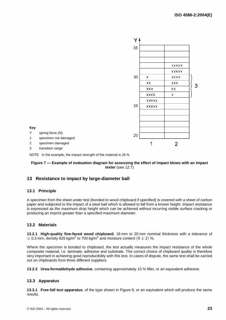
Enter the results of the series of tests on to an evaluation diagram (see Figure 7 for an example) in which theyare subdivided into “Specimen not damaged” and “Specimen damaged”, for each value of spring force used.This results in a transition range in which some specimens are damaged and some undamaged. The impactstrength of the material is the maximum value of the spring force, in newtons, for which no damage occurs in aseries of five tests.
12.8 Test report
The test report shall include the following information:
a) a reference to this part of ISO 4586;
b) the name and type of product;
c) the impact strength, in newtons;
d) any deviation from the specified procedure;
e) the date of the test.
23 C± 2 C
×6
20 mm30 mm
ISO 4586-2:2004(E)
© ISO 2004 – All rights reserved 23
13 Resistance to impact by large-diameter ball
13.1 Principle
A specimen from the sheet under test (bonded to wood chipboard if specified) is covered with a sheet of carbonpaper and subjected to the impact of a steel ball which is allowed to fall from a known height. Impact resistanceis expressed as the maximum drop height which can be achieved without incurring visible surface cracking orproducing an imprint greater than a specified maximum diameter.
13.2 Materials
13.2.1 High-quality fine-faced wood chipboard, to nominal thickness with a tolerance of, density to and moisture content .
Where the specimen is bonded to chipboard, the test actually measures the impact resistance of the wholecomposite material, i.e. laminate, adhesive and substrate. The correct choice of chipboard quality is thereforevery important in achieving good reproducibility with this test. In cases of dispute, the same test shall be carriedout on chipboards from three different suppliers.
13.2.2 Urea-formaldehyde adhesive, containing approximately filler, or an equivalent adhesive.
13.3 Apparatus
13.3.1 Free-fall test apparatus, of the type shown in Figure 8, or an equivalent which will produce the sameresults.
Key
Y spring force (N)
1 specimen not damaged
2 specimen damaged
3 transition range
NOTE In the example, the impact strength of the material is 26 N.
Figure 7 — Example of evaluation diagram for assessing the effect of impact blows with an impact tester (see 12.7)
18 mm 20 mm± 0,3 mm 625 kg/m3 700 kg/m3 (9± 2) %
15 %

ISO 4586-2:2004(E)
24 © ISO 2004 – All rights reserved
13.3.2 Polished steel ball, of mass and diameter , having no damaged orflattened areas on its surface.
13.3.3 Specimen clamping frame, conforming to Figure 9.
Dimensions in millimetres
Key
1 electric power supply
2 transformer and rectifier
3 junction box with two-pin socket
4 junction box with indicator light
5 coiled wire lead
6 foot treadle switch
7 angle iron brackets (attached firmly to wall or column, plumb and perpendicular to base plate)
8 mounting board for test apparatus (medium- or high-density chipboard)
9 6-mm-wide slot
10 slidable machinist’s steel scale
11 electromagnet on sliding mount
12 wing nut
13 steel base plate, levelled and set firmly to floor, and projecting out far enough in front of the stand for the whole of the clamping frame holding the test specimen (see Figure 9) to be placed on it
Figure 8 — Resistance to impact by large-diameter ball (see 13.3.1)
324 g± 5,0 g 42,8 mm± 0,2 mm
450 mm× 450 mm× 20 mm

ISO 4586-2:2004(E)
© ISO 2004 – All rights reserved 25
13.4 Test specimens
Specimens shall be square. For laminates of thickness less than , specimens shall beprepared by uniformly bonding a piece of the sheet under test to the wood chipboard (13.2.1) using thespecified adhesive (13.2.2). The bonded specimens shall be preconditioned for at least 7 days at and relative humidity before being used for the test.
For laminates of thickness and , the effect of bonding the specimen is insignificant and thetest may be conducted with the laminate clamped in the frame in contact with the chipboard.
Laminates of thickness shall be tested clamped in the frame without the chipboard support.
Dimensions in millimetres
Key
1 specimen
2 metal frame
3 upper metal frame, thickness
4 lower metal frame
Figure 9 — Clamping frame (see 13.3.3)
5 mm
230 mm± 5 mm 2,0 mm
23 C± 2 C(50± 5) %
2,0 mm < 5,0 mm
5,0 mm

ISO 4586-2:2004(E)
26 © ISO 2004 – All rights reserved
13.5 Procedure
The test shall be carried out in the laboratory atmosphere, and in cases of dispute it shall be carried out at.
Clamp the specimen in the clamping frame (13.3.3) and place the assembly on the solid base of the free-fall testapparatus (13.3.1). Cover the specimen with a sheet of carbon paper with its coated face in contact with thedecorative surface. Adjust the height scale so that its base is touching the face of the specimen.
Position the electromagnet at any arbitrary height (the specification limit for the material under test is a usefulstarting point).
Place the steel ball (13.3.2) on the energized electromagnet. Operate the release mechanism so that the ballfalls on the specimen, catching the ball on the first rebound so that multiple impacts do not occur.
Examine the impact spot. If cracking is evident, or the carbon imprint is greater than the diameter specified inISO 4586-1, lower the electromagnet and repeat the test. If no cracking is evident and the imprint is smaller thanthe specified diameter, raise the electromagnet and repeat the test. The distance between points of impact, andbetween points of impact and the edge of the specimen, shall be at least . For referee purposes, only oneimpact per specimen shall be made, with the point of impact as near as possible to the centre of the specimen.
Repeat the above procedure, as necessary, to determine the impact resistance, which is defined as themaximum height for which no visible surface cracking, or imprint greater than the specified diameter, occurs infive successive strikes.
13.6 Test report
The test report shall include the following information:
a) a reference to this part of ISO 4586;
b) the name and type of product;
c) the impact resistance, expressed in centimetres;
d) the indentation diameter, expressed in millimetres;
e) any deviation from the specified test method;
f) the date of the test.
14 Resistance to cracking under stress (thin laminates )
14.1 Principle
A specimen, with a drilled hole, taken from the sheet under test is rigidly clamped in a steel fixture. Additionalstress is imposed by heating the clamped specimen at for , and the resistance to cracking assessedby visual examination.
14.2 Apparatus
14.2.1 Clamping device, as shown in Figure 10.
14.2.2 Drilling jig, to facilitate drilling of accurate holes which are free from chipping or cracking. A suitable jigis shown in Figure 11.
14.2.3 Conditioning chamber, with a standard atmosphere of and relative humidity of.
23 C± 2 C
50 mm
2 mm
50 C 6 h
23 C± 2 C(50± 5) %

ISO 4586-2:2004(E)
© ISO 2004 – All rights reserved 27
14.2.4 Electrically heated oven, provided with air circulation and capable of being maintained at.
14.2.5 Hand lens, with approximately magnification.
14.2.6 Lighting, of intensity to .
14.2.7 Drilling machine, operating at less than .
14.2.8 Micrometer thickness gauge, as described in 4.2.1.
14.3 Test specimens
Four specimens shall be prepared, of which three shall be tested and the fourth used as a drill backing piece.
Each specimen shall be long, wide and of the thickness of the sheet undertest. The length of the specimen shall correspond to the cross direction of the sheet.
The specimens shall have a diameter hole drilled in their centres using a drilling jig (14.2.2),the four specimens being clamped together with the decorative surfaces face to face. During the drillingoperation, care shall be taken to avoid chipping, cracking or burning around the edge of the holes. The drill shallbe sharp, and the speed of the drilling machine shall not exceed . After the drilling has been carriedout, the specimen used as a backing piece (i.e. the bottom specimen) shall be discarded.
Any specimen showing cracking, chipping or burning around the edge of the hole shall be discarded, and areplacement prepared. Replacement specimens will also be needed if any specimen movement occurs duringthe test (see 14.4).
Dimensions in millimetres
Key
1 clamping block
2 nut
3 base plate
4 serrated surfaces
Figure 10 — Clamping device (mild steel)
50 C± 2 C
×6
800 lx 1 000 lx
400 r/min
150 mm± 1 mm 50 mm± 0,5 mm
10 mm± 0,5 mm
400 r/min

ISO 4586-2:2004(E)
28 © ISO 2004 – All rights reserved
14.4 Procedure
Measure the thickness of the laminate under test in accordance with Clause 4.
Precondition the specimens for in a standard atmosphere of and relativehumidity.
Preheat the clamping device (14.2.1) in the oven (14.2.4) for at .
Take one specimen from the conditioning chamber (14.2.3), place it immediately in the pre-heated clampingdevice, and tighten the nuts firmly to prevent movement of the specimen. Make reference marks on the surfaceof the specimen adjacent to each clamping block to confirm absence of movement.
Place the clamping device containing the specimen in the oven at .
After , remove the device from the oven, check the reference marks to ensure that the specimenhas not moved, and immediately examine the specimen (while still hot and clamped in the device) with thenaked eye and under magnification for signs of cracking around the hole.
If there is any evidence of movement of the specimen in the clamps during the test period, discard thespecimen without examination and repeat the whole procedure using a new specimen.
Test two further specimens using the same procedure.
Dimensions in millimetres
Key
1 handle
Figure 11 — Drilling jig (mild steel)
48 h 23 C± 2 C (50± 5) %
2 h 50 C± 2 C
50 C± 2 C
6 h± 15 min
×6
6 h

ISO 4586-2:2004(E)
© ISO 2004 – All rights reserved 29
14.5 Expression of results
Express the result of the examination in accordance with the following rating scale (see also Figure 12):
Rating 5: No evidence of cracking
Rating 4: Hairline cracks only visible under magnification
Rating 3: Cracks visible with normal vision (corrected if necessary) from the edge of the hole, but notextending to either edge of the specimen
Rating 2: A crack visible with normal vision (corrected if necessary) from the edge of the hole, extending toone edge of the specimen such that the specimen is not broken into two pieces
Rating 1: Specimen broken into two pieces
The resistance to cracking under stress is expressed as the arithmetic mean of the three individual ratings,rounded to the nearest integer.
14.6 Test report
The test report shall include the following information:
a) a reference to this part of ISO 4586;
b) the name and type of product;
c) the thickness of the sheet under test;
d) the resistance to cracking under stress;
e) any deviation from the specified procedure;
f) the date of the test.
Key
1 to 4 ratings on rating scale (see 14.5)
a Hairline cracks only visible under magnification.
Figure 12 — Classification of types of failure
×6
×6

ISO 4586-2:2004(E)
30 © ISO 2004 – All rights reserved
15 Resistance to scratching
15.1 Principle
Increasing loads are applied in specified steps to a diamond scratching point of defined geometry. Theresistance to scratching of the decorative laminate sheet under test is expressed as a rating which defines themaximum applied load which does not produce a continuous surface scratch. The test result is verified byvisually confirming that the next-higher load-step produces a continuous scratch.
15.2 Materials
15.2.1 Contrast medium, e.g. graphite, talcum, or a solution of dye in alcohol, to contrast with the colour ofthe sheet under test.
15.2.2 Supply of cotton fabric.
15.3 Apparatus
15.3.1 Scratch test apparatus (see Figure 13), consisting of the following parts:
15.3.1.1 Stand, with a device to indicate the horizontal, for example a spirit level.
15.3.1.2 Motor-driven turntable (A), able to rotate about a vertical axis without play. The rotational frequencyshall be .
15.3.1.3 Arm (B), carrying the holder for the diamond, mounted on a ball bearing, with a horizontal axis. Theheight of this axis shall be adjustable so that the arm is exactly horizontal when the scratching point rests on thetest specimen.
15.3.1.4 Means of applying a known load, with an accuracy of to the scratching point with weights( ).
15.3.1.5 Hemispherical diamond scratching point (E), with a point radius of and anincluded angle of (see also Figure 14)4). The diamond shall be mounted in the holder with the flatpart on the leading side of the shank facing the working direction.
15.3.1.6 Clamping disc (F), to keep the test specimen flat.
15.3.2 Viewing enclosure, having a matt black interior and a light source (defined below) located at the top.Its dimensions shall be such that the test specimen is located vertically below the light source and at distanceof . An aperture in the front shall allow inspection of the test specimen at various angles from adistance of . A diagram of a suitable enclosure is shown in Figure 15.
The light source shall consist of a frosted bulb, mounted in a white reflector having an aperture ofapproximately diameter and producing an illumination of to at the specimen surface.
15.3.3 Conditioning chamber, with a standard atmosphere of and relative humidity of.
15.3.4 Electronic balance, suitable for verifying the force applied to the diamond point.
4) Diamond points conforming to these dimensions and profile are available from Cie Weinz, Industrie Edelstein Fabrik,Postfach 2740, D-55743 Idar-Oberstein, Germany. The same product is available through Erichsen GmbH & Co. KG,D-58675 Hemer-Sundwig/Westfalien, Germany. This is an example of a suitable product available commercially. Thisinformation is given for the convenience of users of this part of ISO 4586 and does not constitute an endorsement by ISO ofthis product.
(5± 1) r/min
± 0,01 NC + D
(0,090± 0,003) mm(90± 1)
(600± 5) mm(400± 10) mm
100 W140 mm 800 lx 1 000 lx
(23± 2) C(50± 5) %

ISO 4586-2:2004(E)
© ISO 2004 – All rights reserved 31
Key
1 direction of rotation
Figure 13 — Type of apparatus for measuring resistance to scratching (see 15.3.1)

ISO 4586-2:2004(E)
32 © ISO 2004 – All rights reserved
Dimensions in millimetres
Key
1 diamond holder
2 diamond
3 diamond point
4 optical axis of projector
NOTE The crystal axis of the diamond shall be parallel to the longitudinal axis of the diamond holder. The dimensions ofthe diamond holder are approximate and are given for information only.
Figure 14 — Diamond scratching point (see 15.3.1.5 )

ISO 4586-2:2004(E)
© ISO 2004 – All rights reserved 33
Dimensions in millimetres
Key
1 lamp holder
2 forehead rest (foam-rubber pad)
3 inside wall matt black
4 device for centering test specimen
Figure 15 — Example of suitable viewing enclosure (see 15.3.2)

ISO 4586-2:2004(E)
34 © ISO 2004 – All rights reserved
15.4 Calibration of apparatus
Place the diamond point on the table of the electronic balance (15.3.4) and, with the arm (B) in a horizontalposition, verify that the position marks for the sliding weight (C) correspond to the load values shown in Table 2.If not, move weight C as necessary to achieve the correct loads, and mark the correct positions on the arm (B).
Calibration of the apparatus shall be carried out at least once a year.
15.5 Test specimen
The test specimen shall be a square of side cut from the sheet under test. If required by the typeof apparatus used, a hole of suitable size shall be drilled in the centre of the specimen. One specimen shall betested.
Wipe the specimen surface using cotton fabric (15.2.2) impregnated with a solvent such as acetone. It isimportant that, once cleaned, the surface is not fingered in the test area.
Before making the scratch test, store the specimen for in the standard atmosphere specified in 15.3.3.
15.6 Procedure
Make sure that the stand of the test apparatus is standing horizontally.
Adjust the height of the arm (B) so that it is horizontal when the diamond point rests on the test specimen.
Start the test by making two scratches (each with one revolution of the turntable) at load with a spacing of to between the scratch marks.
On the same specimen, repeat this procedure with loads of , and , leaving a space of to between each pair of scratches.
Remove the specimen from the apparatus and rub the entire scratched area of the surface with a suitablecontrast medium (15.2.1) so that it is engrained in the scratches.
Carefully wipe the surface with clean cotton fabric (15.2.2) to remove any excess contrast medium which is notengrained in a scratch.
NOTE This procedure is necessary to ensure that only true scratches are considered, and superficial hairline polish marksare ignored.
Place the specimen against the centre support in the viewing enclosure (15.3.2) at an angle such that thespecimen can be viewed at right angles to the plane of the surface.
Examine the surface to determine the lowest load for which an almost continuous (i.e. ) double circle ofscratch marks can be seen. The examples shown in Figure 16 can be used as a guide.
A scratch mark is where the contrast medium is engrained in the scratch, and is clearly visible as a line of colourcontrasting with the colour of the specimen.
Superficial polish marks (i.e. where there is a change in gloss level but no continuous engrained contrastmedium) shall be ignored.
The examination of the surface shall take no longer than , and the operator shall ensure that the doublecircle of scratch marks selected is truly continuous.
Table 2 — Load values
Position mark 1,0 N 2,0 N 4,0 N 6,0 N
Load (grams force) 102± 1 204± 1 408± 1 612± 1
(100± 1) mm
72 h
1,0 N1 mm 2 mm
2,0 N 4,0 N 6,0 N 3 mm5 mm
> 90 %
10 s> 90 %

ISO 4586-2:2004(E)
© ISO 2004 – All rights reserved 35
15.7 Expression of results
Express the scratch resistance of the laminate under test in accordance with the rating scale in Table 3 (seealso Figure 16).
Key
1 to 5 ratings on rating scale (see Table 3)
Figure 16 — Examples of scratch resistance test results

ISO 4586-2:2004(E)
36 © ISO 2004 – All rights reserved
15.8 Test report
The test report shall include the following information:
a) a reference to this part of ISO 4586;
b) the name, type and nominal thickness of the product tested;
c) the scratch resistance, expressed in accordance with the rating scale in Table 3;
d) any deviation from the specified test method;
e) the date of the test.
16 Resistance to staining
16.1 Method A
16.1.1 Principle
Test specimens are left in contact with a series of staining agents which are likely to be encountered in everydayuse. The time and conditions of contact are specified for each staining agent. At the end of the specified contactperiod, the specimens are washed and examined for residual surface marks.
If the product under test meets specification requirements when tested with each of the six staining agentsmarked with an asterisk, then it is deemed to comply with the specification for stain resistance. The otherstaining agents are included for information only. In the case of a specific complaint, the staining agent inquestion (selected from group 1, 2 or 3) shall be used to verify the quality of the laminate.
Table 3 — Scratch resistance rating scale
Discontinuous scratches, or faint superficial marks, or no
visible marks
continuous double circle of scratch marks clearly
visible
Rating 5
Rating 4
Rating 3
Rating 2
Rating 1 —
> 90 %
6 N > 6 N
4 N 6 N
2 N 4 N
1 N 2 N
1 N

ISO 4586-2:2004(E)
© ISO 2004 – All rights reserved 37
16.1.2 Staining agents
Staining agent Test conditions Contact time
Group 1
*AcetoneTrichlorethaneOther organic solventsToothpasteHand creamUrineAlcoholic beveragesNatural fruit and vegetable juicesLemonade and fruit drinksMeats and sausagesAnimal and vegetable fats and oilsWaterYeast suspension in waterSalt (NaCl) solutionsMustardLyes, soap solutionsCleaning solution
dodecylbenzene sulfonate alkyl aryl polyglycol ether water
Phenol and chloramine T disinfectantsStain or paint remover based on organic solventsCitric acid ( solution)
16.1.5.1 Procedure AApply staining agentat ambient temperature
to
Group 216.1.5.1 Procedure AApply staining agentat approximately
*Coffee ( of coffee per litre of water)Black tea ( of tea per litre of water)Milk (all types)
Cola beveragesWine vinegarAlkaline-based cleaning agents diluted to concentration
with waterHydrogen peroxide ( solution)Ammonia ( solution of commercial concentrate)Nail varnishNail varnish removerLipstickWater coloursLaundry marking inksBall point inks
16.1.5.1 Procedure AApply staining agentat ambient temperature
Group 3a
*Sodium hydroxide ( solution)
16.1.5.1 Procedure AApply staining agentat ambient temperature
*Hydrogen peroxide ( solution)Concentrated vinegar ( acetic acid)Bleaching agents and sanitary cleaners containing themHydrochloric acid based cleaning agents ( )Acid-based metal cleanersMercurochrome (2,7-dibromo-4-hydroxymercurifluorescein,
disodium salt)*Shoe polishHair colouring and bleaching agentsTincture of iodine (or povidone iodine)Boric acidLacquers and adhesives (except fast-curing materials)Amidosulfonic acid descaling agents ( solution)
Group 4
*Citric acid ( solution)Acetic acid ( solution)
16.1.5.2 Procedure B
a Acids and alkalis, in concentrations stronger than those shown in group 3, which can be contained in commercial cleaning agents, cancause surface damage or marking, even with very short contact times. Any spillage of such materials shall be washed off immediately.
23 %10 %67 %
10 %
16 h 24 h
80 C
120 g9 g
16 h
10 %
3 %10 %
25 %
10 min
30 %30 %
3 % HCl
10 %
< 10 %
10 %5 %
20 min

ISO 4586-2:2004(E)
38 © ISO 2004 – All rights reserved
16.1.3 Apparatus and materials
16.1.3.1 Glass covers (for example watch glasses), to restrict evaporation.
16.1.3.2 Thermometer, range to .
16.1.3.3 Flat-bottomed aluminium vessel, in accordance with 8.3.1.
16.1.3.4 Hotplate, or other suitable heat source.
16.1.3.5 Horizontal inspection surface, illuminated by overhead and low-angle daylight or white fluorescentlight of intensity to .
16.1.3.6 Wetting agent, for example domestic detergent.
16.1.3.7 Solvents, such as ethanol, acetone, methyl ethyl ketone, etc. (see 16.1.5).
16.1.3.8 Soft clean cloth.
16.1.3.9 Hard nylon bristle brush (for example a nail brush).
16.1.4 Test specimens
Individual specimens of any suitable size shall be used, cut from the sheet under test. Alternatively, a singlepiece of laminate, large enough to allow the staining agents to be applied side by side, can be used. Keep thespecimen flat during the test.
In cases of dispute, specimens shall be bonded to chipboard (see 8.4), particularly for procedure B.
16.1.5 Procedures
16.1.5.1 Procedure A
The specimens shall be initially at ambient temperature.
Apply a small quantity (for example 2 or 3 drops) of staining agent to two specimens. The staining agent shallbe at the temperature specified in 16.1.2. Cover the staining agent on one of the two specimens with a glasscover (16.1.3.1).
After the specified contact time has elapsed, if necessary remove the staining agent with a suitable solvent (forexample butyl acetate to remove nail varnish), then wash with water containing a suitable wetting agent(16.1.3.6), and finally with ethanol (16.1.3.7) or other solvents as required to clean the surface. A suitable brush(16.1.3.9) may be used to remove staining agent from textured surfaces.
One hour after washing, place the specimen on the inspection surface (16.1.3.5) and view it from various anglesat a distance of .
16.1.5.2 Procedure B
The specimen shall be prepared in accordance with 8.4.
Apply a small quantity (for example 2 or 3 drops) of the staining agent to the specimen. The staining agent shallbe at ambient temperature.
Fill the vessel (16.1.3.3) with water (to within of the top) and heat it until the water boils vigorously.Discontinue heating and immediately place the vessel containing the boiling water on the surface of thespecimen directly over the pool of staining agent.
0 C 100 C
800 lx 1 000 lx
400 mm
15 mm

ISO 4586-2:2004(E)
© ISO 2004 – All rights reserved 39
After the specified contact time, remove the vessel and wash the specimen with water containing a suitablewetting agent (16.1.3.6) and then with ethanol (16.1.3.7) or other solvents as required to clean the surface.A suitable brush (16.1.3.9) may be used to remove staining agent from textured surfaces.
One hour after washing, place the specimen on the inspection surface (16.1.3.5) and view it from various anglesat a distance of .
16.1.6 Expression of results
The effect on the surface of the specimen shall be expressed in accordance with the following rating scale foreach of the six mandatory staining agents.
Rating 5: No visible change
Rating 4: Slight change of gloss and/or colour, only visible at certain viewing angles
Rating 3: Moderate change of gloss and/or colour
Rating 2: Marked change of gloss and/or colour
Rating 1: Surface distortion and/or blistering
16.1.7 Test report
The test report shall include the following information:
a) a reference to this part of ISO 4586;
b) the name and type of product;
c) an assessment of stain resistance for each staining agent applied, expressed in accordance with the ratingscale given in 16.1.6;
d) any deviation from the specified procedure;
e) the date of the test.
16.2 Method B
16.2.1 Principle
Test specimens are left in contact with a series of staining agents that are likely to be encountered in everydayhousehold use. At the end of the prescribed contact period, the specimens are subjected to a specified cleaningprogramme and examined for any residual surface marks.
This test method may also be used with staining agents other than those specified, to cover specificrequirements agreed between supplier and purchaser.
16.2.2 Materials
16.2.2.1 Commercially available non-abrasive cleaner, containing approximately of butyl cellosolve.
16.2.2.2 Commercially available bleach, containing of sodium hypochlorite.
16.2.2.3 Baking soda.
16.2.2.4 Supply of clean, soft, white cloth.
16.2.2.5 Supply of cotton balls.
16.2.2.6 Acetone.
400 mm
4 %
(5± 0,5) %

ISO 4586-2:2004(E)
40 © ISO 2004 – All rights reserved
16.2.2.7 Distilled water.
16.2.2.8 Staining agents, as listed in Table Table 4.
16.2.3 Apparatus
16.2.3.1 Glass covers, approximately in diameter (for example watch-glasses), one for each testrequiring a cover.
16.2.3.2 Overhead white fluorescent lights, with bulb(s) positioned parallel to the line of sight and providingan intensity of to at the specimen surface.
16.2.3.3 Cellulose sponge, measuring approximately .
16.2.3.4 Hard polyamide (nylon) bristle brush, for example a nail brush.
16.2.3.5 Weight, of one kilogram mass.
16.2.4 Test specimen
The test specimen shall have a surface area sufficient to permit all 15 test reagents to be placed on the surfacein two lines with the individual stains about apart. A specimen is adequate.
Table 4 — Staining agents and their application
Agent number Description Preparation notes Application
1 Distilled water —
Apply 2 drops (an approximately6-mm-diameter spot) and cover with a watch-glass
2 Ethyl alcoholA mixture of ethyl alcohol and
distilled water
3 Acetone —
4 Household ammonia Non-sudsing type
5 citric acid A solution of citric acid in distilled water
6 Vegetable oil —
7 Fresh coffeeOne teaspoon instant coffee per distilled water
8 Fresh tea Brew 1 tea bag per boiling distilled water for two minutes
9 Tomato ketchup —
10 Yellow mustard —
11Tincture of iodine (or povidone iodine)
—
12 Black permanent marker —
Apply a spot approximately in diameter; do not cover
13 HB pencil —
14 Wax crayon —
15 Black paste shoe polish —
NOTE Staining agents shall be kept in closed containers to avoid any change in concentration. Perishable food items shall be kept refrigerated.
50 %50 %
10 %10 %
180 ml
120 ml
10 %
6 mm
25 mm
800 lux 1 100 lux
75 mm× 100 mm× 50 mm
50 mm 100 mm× 400 mm

ISO 4586-2:2004(E)
© ISO 2004 – All rights reserved 41
16.2.5 Procedure
16.2.5.1 Staining procedure
Clean the surface of the test specimen using the cleaner (16.2.2.1) and water on a clean cloth (16.2.2.4). Rinsethe specimen thoroughly and dry using another clean, soft cloth. Allow to dry completely at room temperature.
Position the test specimen on a flat, level, horizontal surface and fix it down (e.g. with tape or weights) to keep itin a horizontal plane.
Place a small quantity of each staining agent (to give a spot approximately in diameter) on the surface ofthe test specimen. The staining agents shall be at room temperature.
If indicated in Table 4, cover each staining agent with a glass cover (16.2.3.1), concave side down, and movethe glass cover gently while in contact with the surface of the test specimen until the entire circular rim of theglass cover is wetted by the staining agent and the staining agent covers an area both under and outside theglass cover.
Mark the test specimen suitably so that each staining agent is identified.
Leave the test specimen undisturbed for a period of to , then remove the glass covers and subject thetest specimen to the cleaning procedures prescribed in16.2.5.2.
16.2.5.2 Cleaning procedures and ratings
Stage 1: Flush the surface of the specimen with water and wipe gently with the sponge (16.2.3.3) moistenedwith water. Blot the specimen dry with a clean, soft cloth (16.2.2.4) and examine the surface in accordance withthe inspection procedure described in 16.2.5.3. If a staining agent is completely removed by stage 1 cleaning(i.e. no visible marks remain), then give that agent a rating of 0. If any stains remain, proceed to stage 2.
Stage 2: Wet the surface of the specimen with the non-abrasive cleaner (16.2.2.1). Moisten the sponge(16.2.3.3) with water and place it on the surface, then place the weight (16.2.3.5) centrally on top of thesponge. Push the weighted sponge back and forth (without any additional downward pressure) over the area tobe cleaned, for 25 cycles (see NOTE). Rinse the specimen with water and wipe dry using a clean, soft cloth(16.2.2.4), then examine the surface in accordance with the inspection procedure (see 16.2.5.3). If a stainingagent is completely removed by stage 2 cleaning (i.e. no visible marks remain), then give that agent a rating of1. If any stains remain, proceed to stage 3.
NOTE In stages 2 and 3, one cycle is a movement forward across the area to be cleaned and back again to the startingposition.
Stage 3: Wet the surface of the specimen with the non-abrasive cleaner (16.2.2.1) and add baking soda toachieve a pasty consistency. Using the stiff-bristle brush (16.2.3.4), scrub any areas where traces of the stainingagents are still visible, for 25 cycles (see NOTE). Rinse the specimen with water and wipe dry using a clean,soft cloth (16.2.2.4), then examine the surface in accordance with the inspection procedure (see 16.2.5.3). If astaining agent is completely removed by stage 3 cleaning (i.e. no visible marks remain), then give that agent arating of 2. If any stains remain, proceed to stage 4.
Stage 4: Using a cotton ball (16.2.2.5) saturated with acetone (16.2.2.6), rub the stain gently for two minutes.Rinse the specimen with water and wipe dry using a clean, soft cloth (16.2.2.4), then examine the surface inaccordance with the inspection procedure (see 16.2.5.3). If a staining agent is completely removed by stage 4cleaning (i.e. no visible marks remain), then that agent shall be given a rating of 3. If any stains remain, proceedto stage 5.
Stage 5: Place a cotton ball (16.2.2.5) saturated with hypochlorite bleach (16.2.2.2) on the stain, and allow it toremain in contact for a period of two minutes. Rinse the specimen with water and wipe dry using a clean, softcloth (16.2.2.4), then examine the surface in accordance with the inspection procedure (see 16.2.5.3). If a
6 mm
16 h 24 h
1 kg

ISO 4586-2:2004(E)
42 © ISO 2004 – All rights reserved
staining agent is completely removed by stage 5 cleaning (i.e. no visible marks remain) then give that agent arating of 4.
Give any staining agent that remains visible after stage 5 a rating of 5.
16.2.5.3 Inspection procedure
After each stage of cleaning, place the specimen on a horizontal surface under the inspection lights (16.2.3.2)and view it at an eye-to-specimen distance of to , and at an angle of to to thehorizontal plane. Rotate the specimen on the horizontal surface and view it from all directions. Direct sunlight orother light sources which might accentuate or minimize the visual effect shall be avoided.
16.2.6 Expression of results
16.2.6.1 Cleanability
Add up the ratings given to the 15 staining agents, and report the cleanability of the test specimen as the sumof the ratings of the 15 agents.
A typical example, showing a specimen with a cleanability of 16, is shown in Table 5.
16.2.6.2 Stain resistance
Assess the stain resistance after completion of the required stages of cleaning, and report as one of thefollowing:
Rating 5: The staining agents have no effect. All marks from the staining agents removed, with noimpairment to surface appearance other than a change in gloss due to cleaning.
Rating 3: The staining agents have a moderate effect. One or more slight stains evident, with no otherimpairment to surface appearance other than a change in gloss due to cleaning.
Rating 1: The staining agents have a severe effect. One or more heavy stains evident and/or disturbance ofthe surface other than a change in gloss due to cleaning.
Record any staining agents that produce a moderate or severe effect.
Table 5 — A typical example of cleanability
Agent number Stain Rating
1 Distilled water 0
2 Ethyl alcohol 0
3 Acetone 0
4 Household ammonia 0
5 citric acid 0
6 Vegetable oil 0
7 Fresh coffee 0
8 Fresh tea 0
9 Tomato ketchup 1
10 Yellow mustard 2
11 Tincture of iodine (or povidone iodine) 2
12 Black permanent marker 2
13 HB pencil 2
14 Wax crayon 3
15 Black paste shoe polish 4
Total: 16
750 mm 900 mm 45 75
10 %
10 %

ISO 4586-2:2004(E)
© ISO 2004 – All rights reserved 43
16.3 Test report
The test report shall include the following information:
a) a reference to this part of ISO 4586;
b) the name, type, and nominal thickness of the product;
c) the cleanability of the specimen, expressed in accordance with 16.2.6.1;
d) the stain resistance of the specimen, expressed in accordance with 16.2.6.2, plus a note of any stainingagents that produced a moderate or severe effect;
e) any deviation from the test method specified;
f) the date of the test.
17 Lightfastness
17.1 Method A
17.1.1 Principle
A test specimen taken from the laminate under test is exposed to daylight simulated by the filtered light of oneor more xenon-arc lamps. The effect on the colour of the specimen, at a specified radiant exposure, is assessedby the contrast between the exposed and unexposed portions of the test specimen. The radiant exposure isdetermined both instrumentally and by assessing the effect on blue wool references which are exposedsimultaneously.
Daylight spectral distribution is specified since decorative laminates may, in certain applications, be exposed todirect daylight through open windows.
17.1.2 Apparatus
17.1.2.1 Test device, as specified in ISO 4892-1 and ISO 4892-2, equipped with:
— one or more xenon-arc lamps, filtered to provide a spectral energy distribution which closely approximatesto that of solar irradiance as described in CIE Publication No. 85:1989, Table 4, and ISO 4892-2:1994,Subclause 4.1.1, method A;
— stainless-steel specimen holders, in the form of an open frame, which provide the test specimens with asolid backing;
— a black-standard thermometer as specified in ISO 4892-1;
— a photoelectronic sensor (radiometer) of one of the types specified in ISO 9370 to measure the irradianceand the radiant exposure at the specimen surface in the wavelength range to , or at .
17.1.2.2 Conditioning chamber, maintained at a temperature of and a relative humidity of.
17.1.2.3 Viewing enclosure, having a matt interior colour corresponding approximately to Munsell N5. It shallbe equipped with an artificial light source, located at the top, simulating average north sky daylight (e.g.tungsten-halogen incandescent lamps) and generating a colour temperature of and at least
at the surface of the specimen. The viewing enclosure shall be placed in a position where thesurrounding lighting conditions will not affect the visual assessment of the specimen.
300 nm 400 nm 340 nm
(23± 2) C(50± 5) %
(6 500± 200) K800 lux

ISO 4586-2:2004(E)
44 © ISO 2004 – All rights reserved
17.1.3 Test specimen
One test specimen shall be prepared in accordance with ISO 4892-1. It shall be representative of the laminateto be tested, be cut to the size required for the specimen holder used, and be appropriate for the method ofassessment after exposure.
17.1.4 Procedure
The test specimen and a set of blue wool references 5, 6 and 7 (as specified in ISO 105-B02) shall be exposedsimultaneously. Blue wool references 5 and 7 are included to provide confirmation that wool reference 6 hasdegraded to the specified degree of contrast.
Using opaque stainless-steel covers, shield approximately one-half of both the test specimen and the set of bluewool references.
Carry out the test in accordance with ISO 4892-2 under the following operating conditions:
— irradiance at the test specimen surface in the wavelength range to : ; or atwavelength : ;
— black-standard temperature: ;
— relative humidity: .
Discontinue the exposure when the contrast between the exposed and unexposed portions of blue woolreference 6 is equal to grade 4 on the grey scale, as defined in ISO 105-A02 (see NOTE 1).
Measure and record the radiant exposure (over to , or at ).
Remove the test specimen from the apparatus, take off the cover, and leave the specimen for in darkconditions in the conditioning chamber (17.1.2.2) to prevent extraneous darkening and/or photochromism (seeNOTE 2).
NOTE 1 Although the use of blue wool references is no longer the preferred method of measuring radiant exposure (seeISO 4892-2:1994), the method is still in common use and is therefore permitted. Once sufficient data have been collected,the end-point of the test will be defined by the level of radiant exposure.
NOTE 2 Extraneous darkening and/or photochromism are due to the shock effect of accelerated exposure, and are notcharacteristics of natural exposure. Keeping the specimens in dark conditions for allows recovery from these effects.
17.1.5 Assessment of specimen and expression of results
Place the test specimen in the viewing enclosure (17.1.2.3).
Examine the surface of the test specimen with the naked eye, corrected if necessary, at a distance ofapproximately for any change in colour, assessing the contrast between the exposed and unexposedportions of the test specimen in terms of a grade on the grey scale in accordance with ISO 105-A02.
The lightfastness of the test specimen is expressed in terms of the contrast being greater than, equal to or lessthan grade 4 on the grey scale.
17.1.6 Test report
The test report shall include the following information:
a) a reference to this part of ISO 4586;
b) the name, type and nominal thickness of the product;
c) details of the apparatus used;
d) the irradiance at the test specimen surface;
300 nm 400 nm (60± 3) W/m2
340 nm (0,5± 0,03) W/m2
(65± 3) C
(50± 5) %
300 nm 400 nm 340 nm
(24± 2) h
24 h
50 cm

ISO 4586-2:2004(E)
© ISO 2004 – All rights reserved 45
e) the radiant exposure;
f) the exposure time;
g) the lightfastness of the specimen;
h) any deviation from the method specified;
i) the date of the test.
17.2 Method B
17.2.1 Principle
The test assesses the effect on the colour of a test specimen of exposure to a filtered xenon-arc light sourcehaving a frequency range approximating to sunlight through window glass.
It is not intended to show the resistance to continuous exposure to outdoor weathering conditions.
17.2.2 Materials
17.2.2.1 White petroleum jelly.
17.2.3 Apparatus
17.2.3.1 Suitable xenon-arc test apparatus, as specified in ISO 4892-1 and ISO 4892-2, capable ofproviding radiant energy closely approximating to sunlight, with a spectral bandpass of to andwith appropriate filtering to simulate daylight through window glass. The apparatus shall incorporate a systemfor mounting specimen holders at an equal radial distance from the centre of the light source and revolving themaround the light source so as to provide equal radiant exposure.
17.2.3.2 Specimen holders, suitable for the test apparatus, and incorporating a mask to cover half of theexposed face of the test specimen.
17.2.3.3 Overhead white fluorescent lights, with bulb(s) positioned parallel to the line of sight and providingan intensity of to at the specimen surface.
17.2.3.4 Conditioning chamber, maintained at a temperature of and a relative humidity of.
17.2.4 Standardization of apparatus
Calibration, maintenance and filter changes shall be strictly in accordance with the equipment manufacturer'srecommendations.
The calibration wavelength for the xenon unit shall be
17.2.5 Test specimen
The test specimen shall be of the size specified for the test apparatus being used. The length of the specimenshall be in the machine direction of the laminate.
Condition the specimen for at least prior to the test at a temperature of and relative humidity.
280 nm 800 nm
800 lux 1 100 lux
(23± 2) C(50± 5) %
420 nm.
48 h (23± 2) C(50± 5) %

ISO 4586-2:2004(E)
46 © ISO 2004 – All rights reserved
17.2.6 Procedure
Mount the test specimen in a specimen holder (17.2.3.2) so that approximately one-half of the specimen isexposed to the light source, the other half being covered by the mask. Fill all the specimen holders, utilizingblanks if necessary, and keep them filled during the whole of the test, in order to maintain correct air-flowconditions through the test chamber.
Carry out the test under the operating conditions specified in Table 6.
NOTE 1 The setting of the wet-bulb temperature in relation to the dry-bulb temperature is designed to maintain a relativehumidity of .
NOTE 2 All test parameters should be maintained as close as possible to the required settings.
The black-panel thermometer shall be mounted at the same distance from the light source as the testspecimen. The black coating shall be maintained in good condition in order to achieve as accurately as possiblethe black-body temperature of the panel.
At the conclusion of the specified exposure period, remove the test specimen from its holder and allow it tocondition at room temperature for a period of .
After this conditioning period, examine the specimen within by placing the specimen on a horizontal surfaceunder the inspection lights (17.2.3.3) and viewing it at an eye-to-specimen distance of to , andat an angle of to from the horizontal plane. Rotate the specimen on the horizontal surface and view itfrom all directions. Direct sunlight or other light sources which might accentuate or minimize the visual effectshall be avoided.
If a difference in appearance is evident between the exposed and unexposed areas of the test specimen, coatthe surface of the specimen with a thin film of white petroleum jelly (17.2.2.1) and re-examine it. If the differencepersists, report the difference as a colour change; if it disappears, report it as a change in surface finish.
17.2.7 Expression of results
Express the result of the examination in accordance with the following rating scale:
Rating 5: No change in colour or surface finish
Rating 4: A slight change in colour or surface finish visible only at certain viewing angles and directions
Rating 3: A moderate change in colour or surface finish that is just visible at all viewing angles anddirections
Rating 2: A marked change in colour or surface finish that is very evident at all viewing angles anddirections
Rating 1: Surface blistering and/or cracking
Table 6 — Operating conditions
Parameter Setting Tolerance
Total irradiance
Irradiance level
Black-panel temperature
Dry-bulb temperature
Wet-bulb temperature
Conditioning-water temperature
Duration of exposure
Power adjustment Automatic To maintain steady irradiance levels, allowing forageing of xenon burners and solarization of filters
(50± 5) %
24 h
4 h750 mm 900 mm
45 75
285,1 kJ/m2 ± 2,0 kJ/m2
1,10 W/m2 ± 0,03 W/m2
70 C ± 3 C
50 C ± 3 C
39 C ± 1 C
20 C ± 3 C
72 h ± 1 %

ISO 4586-2:2004(E)
© ISO 2004 – All rights reserved 47
17.2.8 Test report
The test report shall include the following information:
a) a reference to this part of ISO 4586;
b) the name, type and nominal thickness of the product;
c) details of the apparatus used;
d) the lightfastness of the specimen, expressed in accordance with 17.2.7;
e) any deviation from the method specified;
f) the date of the test.
17.3 Method C (Resistance to colour change in light from an enclosed carbon-arc lamp)
17.3.1 Principle
Part of a test specimen taken from the sheet under test is exposed, together with standard blue woolspecimens, to the light of an enclosed carbon-arc lamp. The light dosage is determined by the effect on the woolspecimens, and the effect on the test specimen is assessed at a specified light dosage by the contrast betweenthe exposed and unexposed portions of the specimen.
The test is fully described in ISO 4892:1981.
17.3.2 Apparatus
As specified in ISO 4892:1981, without control of humidity.
17.3.3 Test specimen
As specified in ISO 4892:1981.
17.3.4 Procedure
Carry out the test using the single-exposure method described in ISO 4892:1981, and discontinue the exposurewhen blue wool standard No. 5 shows a contrast between exposed and unexposed portions equal to grade 4 onthe grey scale.
17.3.5 Evaluation and expression of results
Examine the contrast between the exposed and unexposed portions of the test specimen and record it in termsof grades on the grey scale.
Express the result in relation to the resistance to colour change of blue wool standard No. 5 as one of thefollowing:
Specimen contrast(grey scale grade No.)
Resistance to colour change(blue wool standard No.)
4 5
> 4 > 5
< 4 < 5

ISO 4586-2:2004(E)
48 © ISO 2004 – All rights reserved
17.3.6 Test report
The test report shall include the following information:
a) a reference to this part of ISO 4586;
b) the name and type of product;
c) the resistance of the specimen to colour change, expressed as greater than, equal to, or less than of bluewool standard No. 5;
d) any deviation from the specified procedure;
e) the date of the test.
18 Resistance to cigarette burns
18.1 Method A
18.1.1 Principle
Specimens from the sheet under test are bonded to wood chipboard to simulate service conditions andsubjected to the heat from burning cigarettes placed on their surfaces. The test result is expressed in terms ofany resultant damage.
18.1.2 Materials
18.1.2.1 Fine-faced wood chipboard, to nominal thickness with a tolerance of ,density to and moisture content .
18.1.2.2 Urea-formaldehyde adhesive, containing approximately filler, or an equivalent adhesive.
18.1.2.3 Pale-tobacco cigarettes without filters, from each of three well known brands, each with a mass of to for a length of and with the tobacco evenly distributed over its length. They shall be kept in
the standard atmosphere (see 18.1.4) for at least before being used for the test.
18.1.2.4 Ethanol, by volume.
18.1.2.5 Soft cloth.
18.1.3 Test specimen
The specimen shall be prepared by uniformly bonding a piece of the sheet under test to the wood chipboard(18.1.2.1), using the specified adhesive (18.1.2.2). The bonded specimen shall be kept in the standardatmosphere (see 18.1.4) for at least 7 days before being used for the test. One specimen square shall be prepared.
18.1.4 Apparatus
18.1.4.1 Conditioning chamber, with a standard atmosphere of and relative humidity of.
18.1.5 Procedure
Ignite one cigarette from one of the brands and let it burn to consume a length of approximately .
Place the burning cigarette in full-length contact with the horizontal surface of the specimen in a draught-freearea so that the glued seam of the cigarette is not in contact with the specimen. Allow the cigarette to continue
18 mm 20 mm ± 0,3 mm625 kg/m3 700 kg/m3 (9± 2) %
15 %
1,0 g 1,1 g 70 mm24 h
95 %
230 mm± 5 mm
23 C± 2 C(50± 5) %
10 mm

ISO 4586-2:2004(E)
© ISO 2004 – All rights reserved 49
burning until an additional length is consumed. If the cigarette goes out before this occurs, repeat thetest.
Follow the same procedure with the two cigarettes from the other two brands.
Remove any superficial combustion residues with a soft cloth moistened with alcohol. Examine the surface withthe naked eye, corrected if necessary, for any changes such as discolouration, cracks or blisters.
18.1.6 Expression of results
Express the result for each area of cigarette contact in accordance with the following rating scale:
Rating 5: No visible change
Rating 4: Slight change of gloss only visible at certain viewing angles and/or slight brown stain
Rating 3: Moderate change of gloss and/or moderate brown stain
Rating 2: Severe brown mark, but no destruction of the surface
Rating 1: Blistering and/or cracks
18.1.7 Test report
The test report shall include the following information:
a) a reference to this part of ISO 4586;
b) the name and type of product;
c) the brands of cigarette used;
d) the cigarette burn resistance of the specimen, expressed as the arithmetic mean of the three individualratings, rounded to the nearest integer;
e) any deviation from the specified procedure;
f) the date of the test.
18.2 Method B (simulated test using electric heater)
18.2.1 Principle
Specimens taken from the sheet under test, and bonded to wood chipboard to simulate service conditions, areexposed to local radiant heat from an electric heater. The resistance of the material is assessed in terms of theduration of exposure needed to cause visible damage.
18.2.2 Materials
18.2.2.1 Fine-faced wood chipboard, to nominal thickness with a tolerance of ,density to and moisture content .
18.2.2.2 Urea-formaldehyde adhesive, containing approximately filler, or an equivalent adhesive.
18.2.3 Apparatus
18.2.3.1 Heating-element support (see Figure 17), consisting of electrically non-conducting laminated sheet.
20 mm
18 mm 20 mm ± 0,3 mm625 kg/m3 700 kg/m3 (9± 2) %
15 %

ISO 4586-2:2004(E)
50 © ISO 2004 – All rights reserved
18.2.3.2 Heating element (see Figure 17), of iron-aluminium alloy, having the following characteristics:
— cross-section of flat wire: ;
— wire length:
— electrical resistance: .
This heating element shall be in the form of a spiral (outside diameter approximately , external ring notincluded).
18.2.3.3 Adjustable mounting, for the heating element (see Figure 17), consisting of an externally threadedbrass sleeve located vertically by two knurled brass nuts.
18.2.3.4 Calibration block (see Figure 18), of electrically insulating laminate, on which are mounted:
a) A disc support, made from homogeneous heat-insulating diatomaceous-earth sheet material of bulk density to , and of thermal conductivity to in the temperature
range to .
b) A stainless-steel disc, to the bottom of which is silver-soldered an iron-constantan thermocouple. Thesurface of the disc shall be highly polished and flat, and shall be in the same plane as the surface of the discsupport. The disc shall be clamped firmly on its support.
18.2.3.5 Glass-windowed cover (see Figure 19), with the following nominal dimensions:
length
width
height
18.2.3.6 Stopwatch.
18.2.3.7 Power source, producing a constant current for the heating element.
This source may be
a) either a series of well charged accumulators with elements in good condition, able to provide the heatingelement with a power greater than ,
b) or an electrical unit powered from the mains supply.
18.2.3.8 Control circuit, to adjust and maintain the power consumption of the heating element with anaccuracy of . Measurements are made by means of a voltmeter and an ammeter. A circuit for use witha supply is shown in Figure 20.
18.2.3.9 Potentiometer, for measuring the temperature of the stainless-steel disc.
18.2.3.10 Cotton wick, saturated with liquid paraffin.
18.2.3.11 Conditioning chamber, with a standard atmosphere of and relative humidity of.
1,6 mm× 0,25 mm
480 mm;
1,8Ω ± 0,1Ω
15 mm
512 kg/m3 576 kg/m3 0,10 W/(m·K) 0,12 W/(m·K)0 C 300 C
240 mm
110 mm
80 mm
20 W
± 0,1 %115 V
23 C± 2 C(50± 5) %

ISO 4586-2:2004(E)
© ISO 2004 – All rights reserved 51
Dimensions in millimetres
Key
1 heating-element support
2 heating element
3 silver-soldered connection
4 two screws F/90, Ø
5 two knurled nuts, thickness , fine threaded pitch , Ø int. , Ø ext.
6 tube, Ø , length , externally threaded, fine threaded pitch
7 nut HM4
8 earthing terminal
9 four nuts HM4
10 four washers M4
11 electrical resistance coil soldered to the threaded tube at three points on the circumference
12 four screws R 4/12
Materials: Electrically insulating laminate, screws and threaded tube.
Figure 17 — Electric heater for cigarette test (see 18.2.3.1, 18.2.3.2 and 18.2.3.3)
4/18 mm
3 mm 0,75 mm 27 mm 39 mm
20/27 mm 17 mm 0,75 mm

ISO 4586-2:2004(E)
52 © ISO 2004 – All rights reserved
Dimensions in millimetres
Key
1 calibration block
2 disc support (material: diatomaceous earth or similar insulating material)
3 stainless-steel disc, Ø , thickness , central hole Ø
4 iron-constantan thermocouple silver-soldered in a hole (Ø ) in the stainless-steel disc
5 duct, Ø
6 holes, Ø
7 circular depression
8 electrically insulating laminate washer, Ø ext. , Ø int. , thickness
9 eight screws F/90, Ø
Materials: Electrically insulating laminate.
Figure 18 — Calibration block for cigarette test (see 18.2.3.4)
12,5 mm 0,4 mm 1 mm
1 mm
3 mm
3,5 mm
57 mm 3 mm 7 mm
3/10 mm

ISO 4586-2:2004(E)
© ISO 2004 – All rights reserved 53
Dimensions in millimetres
Key
1 two glass-covered observation windows facing each other — size (nominal)
Figure 19 — Apparatus cover for cigarette test (see 18.2.3.5)
180 mm× 50 mm

ISO 4586-2:2004(E)
54 © ISO 2004 – All rights reserved
Key
1 wire
2 heater cord
3 resistor heating element
List of items
Symbol Function Description
F-1 Line fuse 5 ALine fuse mounting
F-2 Control fuse 1 A
Control fuse mounting Extractor postF-3 Power fuse 10 A
Power fuse mounting Extractor post
M-1 Ammeter 0 A to 10 A alternating currentM-2 Voltmeter 0 V to 6 V alternating current (452/V)S-1 Line connector Male connector
SW-1 Line switch DPST toggle switchT-1 Autotransformer Primary: 115 V;
secondary: 0,130 V; 5 A
T-2 Power transformer Primary: 115 V;secondary: 5,25 V; 22 A
T-3 Voltage stabilizer ; 115 V output
Figure 20 — Wiring diagram of control circuit for cigarette test (see 18.2.3.8)
5 mm2
5 mm2
100 V · A ± 1 %

ISO 4586-2:2004(E)
© ISO 2004 – All rights reserved 55
18.2.4 Test specimens
Each specimen shall be prepared by uniformly bonding a piece of the sheet under test to the wood chipboard(18.2.2.1), using the specified adhesive (18.2.2.2). The bonded specimens shall be kept in the conditioningchamber (18.2.3.11) for at least 7 days before being used for the test. Three specimens measuring
shall be prepared.
18.2.5 Procedure
18.2.5.1 Calibration
The bottom of the heating element shall be flat.
Adjust the heating element so that the distance between its lower side and the disc is (withoutincluding the edging ring).
Stand the heating-element support (18.2.3.1) on its end and adjust the power input to approximately .
Allow to heat for .
Blacken the stainless-steel disc with the flame from the burning paraffin-saturated wick to produce a uniformcoating of carbon. The insulating support shall be kept clean.
Place the heating-element support on the calibration block so that the heating element covers the disc.
Cover the assembly to exclude draughts.
Allow the heating element to warm the disc for in order to produce a final temperature of approximately.
It is not necessary to record the intermediate temperatures. If the final temperature is not , adjust thepower input. Lift up the heating-element support without disconnecting the power supply and stand it in thevertical position.
Keep the calibration block under the cover until the disc cools to , then replace the heating-element support on the calibration block and cover immediately.
Start the stopwatch when the heating-element support and the calibration block touch. Measure and record thetemperature at intervals, for a period of .
The calibration curve shall be within the following limits:
Time (min) Temperature (°C)
0
1
2
3
4
5
6
7
8
9
10
(230± 2) mm× (80± 1) mm
8 mm± 0,1 mm
20 W
30 min
10 min285 C
285 C
40 C± 0,5 C
1 min 10 min
40± 0,5
215± 3
251± 3
265± 3
274± 3
279± 3
282± 3
284± 3
285± 3
286± 3
287± 3

ISO 4586-2:2004(E)
56 © ISO 2004 – All rights reserved
During the calibration, the current shall not fluctuate. If necessary, adjustment shall be made and furthercalibration carried out until the desired curve is obtained (each time allowing the calibration block to cool to
).
When the calibration curve is obtained, proceed with the test.
18.2.5.2 Test
Position the heater on the specimen so that the resistance coil is at least from the nearest edge, start thetimer at the same time, and cover the assembly with the enclosure within .
Continue the test until the specimen fails or for . Failure is defined for this purpose as blistering, charring,permanent discolouration or crazing. If failure occurs in less than , record the time of failure.
The test shall be invalid if
a) the heating element is moved during the test or is not positioned above the surface of thespecimen;
b) the power input to the heating element does not remain constant at the level of last calibration;
c) the cover is removed at any time during the test.
Repeat the test on additional specimens to obtain three valid results.
The calibration of the heating element shall be checked at least once per hour, and at any time that irregularresults or an unsteady power input are observed.
18.2.6 Expression of results
Report the result as the average of the three times to failure, in seconds.
If one or two tests are discontinued without failure, their results shall be taken as for the purpose ofcalculating the average. If all three tests are discontinued without failure, the result shall be recorded as “nofailure in ”.
18.2.7 Test report
The test report shall include the following information:
a) a reference to this part of ISO 4586;
b) the name and type of product;
c) the average time to failure, or a statement that failure did not occur in ;
d) the type of failure, for example blistering, crazing;
e) any deviation from the specified procedure;
f) the date of the test.
40 C± 0,5 C
40 mm2 s
10 min10 min
8 mm± 0,1 mm
600 s
600 s
600 s

ISO 4586-2:2004(E)
© ISO 2004 – All rights reserved 57
19 Formability
19.1 Method A
19.1.1 Principle
A test specimen is subjected to radiant heat on its decorative face until the reverse side reaches apredetermined temperature. It is then formed in a jig to a specified radius and angle, and cooled beforeexamining for signs of failure on the bend line.
The test is carried out with specimens cut in the longitudinal and transverse directions of the sheet and with thedecorative face on both the outside and the inside of the bend.
This method is an alternative test method to be used when so designated by the national authority or byagreement between supplier and purchaser.
19.1.2 Apparatus
19.1.2.1 Radiant heater, consisting of two electrically heated sheathed elements of total rating,mounted parallel and in a horizontal plane in a metal-lined trough approximately wide and deep (inside dimensions), the height of the heating elements above the bottom of the trough being such that,when a specimen is laid across the trough, the specimen is at a distance of above the heatingelements. A windscreen enclosure to surround three sides and the top is advisable.
19.1.2.2 Variable-output transformer, with a voltage indicator, to control the voltage applied to the heater.
19.1.2.3 Temperature indicators (thermal crayons or waxes), with melting points covering the required rangeof temperatures. Other types of temperature indicator with equal or better precision may also be used(e.g. infra-red thermometers, colour-change indicators).
19.1.2.4 Stopwatch, or other suitable timer.
19.1.2.5 Forming apparatus (see Figure 21), with forming blocks machined from straight-grained wood.
It is recommended that a fitting be placed on top of the male forming blocks which can be securely attached tothe ram of the press used in conjunction with these blocks.
19.1.2.6 Conditioning chamber, with a standard atmosphere of and relative humidity of.
19.1.2.7 Strips, of plain-colour white laminate conforming to the specifications for HGP given in ISO 4586-1,measuring and with the major axis in the machine direction of the fibrous sheet material fromwhich the laminate was made, to be used for calibration purposes.
19.1.3 Test specimens
The specimens shall have dimensions of approximately , shall be of the thickness of thesheet under test and shall be sanded smooth at the long edges to remove hairline cracks.
Eight specimens shall be tested, four with their major axis in the machine direction of the fibrous sheet materialfrom which the laminate was made, and four at right angles to this direction.
The specimens shall be conditioned for at least at and relative humidity beforetesting.
1 500 W110 mm 125 mm
76 mm± 1,0 mm
23 C± 2 C(50± 5) %
200 mm× 50 mm
200 mm× 50 mm
24 h 23 C± 2 C (50± 5) %

ISO 4586-2:2004(E)
58 © ISO 2004 – All rights reserved
19.1.4 Procedure
19.1.4.1 Calibration of test apparatus
Turn on the heater (19.1.2.1) prior to conducting the test, with the variable transformer (19.1.2.2) atfull-line voltage.
Dimensions in millimetres
Key
1 rod, Ø
2 spring
3 tube, Ø
4 pipe flange
5 base,
6 slot
7 sheet metal guide
8 male forming block with the radius required for the type of laminate being tested
Figure 21 — Forming apparatus (radiant heat test) (Method A) (see 19.1.2.5)
25 mm
38 mm
19 mm× 305 mm× 560 mm
90
30 min

ISO 4586-2:2004(E)
© ISO 2004 – All rights reserved 59
Use a temperature indicator (19.1.2.3) with a melting point of to make several marks about longnear the centre of the non-decorative surface of several calibration strips (19.1.2.7).
Place a calibration strip on the heating trough so that the heat is applied to the decorative face. Adjust the inputvoltage by means of the variable transformer so that the time taken to reach is per ofcalibration strip thickness, accurate to within .
After three or more consecutive calibration strips reach within the prescribed time , begin the testand maintain and record the voltage setting.
19.1.4.2 Test procedure
Place the male forming block with radius as recommended by the laminate manufacturer, or as required byISO 4586-1, into the forming apparatus (19.1.2.5).
Measure the thickness of the sheet as specified in Clause 4 and record.
Use a temperature indicator with a melting point as recommended by the laminate manufacturer to makeseveral marks about long on the surface that will be the inside of the bend and near the centre of eachspecimen.
Place a specimen on the heating trough so that the heat is applied to the side opposite the side marked with thetemperature indicator.
Remove the specimen when the temperature indicator is completely melted in the area to be formed, place thespecimen within in the bending jig and carry out the forming test.
The closing time of the male forming block after the initial contact with the specimen shall be to . Allowthe specimen to cool in the closed bending jig.
Remove and inspect the specimen after allowing it to cool for not less than . Failure to form satisfactorilyshall be defined by the presence of cracks, blisters or delamination.
Carry out the test to assess the formability in both the longitudinal and transverse directions of the sheet andwith the decorative face on both the inside and the outside of the bond, testing two specimens in each case.
19.1.5 Test report
The test report shall include the following information:
a) a reference to this part of ISO 4586;
b) the name and type of product;
c) the thickness of the laminate;
d) the forming radius;
e) the direction of the major axis of the specimen;
f) whether the decorative face is inside or outside the bend;
g) any failure: defects, for example cracks and their extent, blisters, delamination or discolouration;
h) any deviation from the specified procedure;
i) the date of the test.
163 C 100 mm
163 C 1 s 0,025 mm± 2 s
163 C ± 2 s
100 mm
5 s
0,5 s 1 s
60 s

ISO 4586-2:2004(E)
60 © ISO 2004 – All rights reserved
19.2 Method B
19.2.1 Principle
A specimen from the sheet under test is subjected to infrared radiation until the heated face reaches apredetermined temperature. It is then formed on a jig made of wood (for example premachined chipboard) to aspecified radius, allowed to cool and examined for signs of failure.
The test is repeated with specimens cut in each direction of the sheet and with the decorative face on both theoutside and the inside of the bend. The formability is assessed in terms of the success or failure of the formingprocess at the specified radius.
This method is an alternative test method which is close to industrial practice and allows for adjustment of all thetest variables in order to establish the optimum conditions for the forming of individual materials. It is possiblethat different laminates, even from the same manufacturer, may require different forming conditions. Theconditions shall be specified by the laminate manufacturer, and the requirements shall be considered to besatisfied if the forming operation is successful under these conditions.
19.2.2 Apparatus
19.2.2.1 Radiant heater element5), fitted with a reflector6), the distance and orientation relative to the testspecimen being adjustable (see Figure 22).
This heater unit is mounted on a hinged support allowing it to be quickly moved away to the rear.
19.2.2.2 Forming jig, of wood, chipboard or other material having a similar thermal conductivity, the front ofwhich is rounded to a specified radius. The jig is easily replaceable, and it is possible to use a series of formingjigs machined to specified radii (for example , , , , ) (see Figure 22).
19.2.2.3 Clamping device, for the test sample (see Figure 22).
19.2.2.4 L-shaped forming bar, with a handle (see Figure 22).
19.2.2.5 Temperature indicators (thermal crayons or waxes), with melting points covering the required rangeof temperature. Other types of temperature indicator with equal or better precision may also be used(e.g. infra-red thermometers, colour-change indicators).
19.2.2.6 Stopwatch, or other suitable timer.
19.2.2.7 Thickness gauge (ratchet-type micrometer) (see 4.2.1).
19.2.2.8 Conditioning chamber, with a standard atmosphere of and relative humidity of.
19.2.3 Test specimens
The specimens shall measure approximately and be of the thickness of the sheet under test.They shall be sanded smooth at the edges to remove any hairline cracks.
At least twelve specimens shall be prepared, six with their major axes in the machine direction of the fibroussheet material from which the laminate was made, and six at right angles to this direction.
5) For example, Elstein Type FSR 650 W - 220 V ( ).
6) For example, Elstein Type REO .
These are examples of suitable products available commercially. This information is given for the convenience of users ofthis part of ISO 4586 and does not constitute an endorsement by ISO of these products.
245 mm× 60 mm
250 mm
8 mm 9 mm 10 mm 11 mm 12 mm
23 C± 2 C(50± 5) %
180 mm× 90 mm

ISO 4586-2:2004(E)
© ISO 2004 – All rights reserved 61
Dimensions in millimetres
a) Profile
b) Plan view B-B
Figure 22 — Forming apparatus (Method B) (see 19.2.2)

ISO 4586-2:2004(E)
62 © ISO 2004 – All rights reserved
Dimensions in millimetres
c) Vertical section A-A
d) Details of L-shaped forming barKey1 raising handle2 reflector3 ceramic parabolic heater4 clamping device5 L-shaped forming bar, 6 slotted support bat (for blister test only)7 heater element8 specimen9 forming jig10 clamping device11 adjustable stops12 specified radius13 stainless steel, thickness 14 handle15 felt
Figure 22 — Forming apparatus (Method B) (see 19.2.2) (continued)
40 mm× 40 mm× 2,5 mm
2,5 mm

ISO 4586-2:2004(E)
© ISO 2004 – All rights reserved 63
The specimens shall be conditioned for at and relative humidity before testing.
19.2.4 Procedure
19.2.4.1 General
Measure the thickness of the specimens as specified in Clause 4.
Use the forming jig corresponding to the radius specified in ISO 4586-1.
Turn on the heater element at least prior to starting the test.
19.2.4.2 Calibration of test apparatus
Clamp a specimen on the forming jig (19.2.2.2).
Using a temperature indicator (19.2.2.5), make a mark on the upper face in the area to be formed.
Lower the heater element (19.2.2.1) over the specimen and start the timer (19.2.2.6) immediately. The time toreach shall be .
Move the heater element quickly to the rear.
If the time to reach is not , adjust the height of the heater element relative to the specimenuntil the setting is found where the indicator melts in this time.
19.2.4.3 Test procedure
Clamp the specimen on the forming jig.
Make a mark on the upper face in the area to be formed, using a temperature indicator (19.2.2.5) in thetemperature range recommended by the laminate manufacturer.
Lower the heater element over the test sample, and start the timer immediately.
Observe the temperature indicator mark for signs of melting. When the mark melts completely, stop the timer,and note the heating time required for the specimen to reach the forming temperature.
Move the heater element quickly to the rear.
Using the handle, immediately but smoothly lower the forming bar (19.2.2.4). The forming time shall not exceed.
Keep the bar lowered for to allow the formed specimen to cool in the forming apparatus.
Raise the bar and release and remove the formed specimen.
Carry out the test on specimens cut in both the machine and the cross-machine directions, and with thedecorative face on both the inside and the outside of the bend, to obtain three results under the conditionsspecified.
If the dimensions of the equipment permit, several specimens can be formed side by side simultaneously.
Observe the formed specimens with the naked eye, corrected if necessary.
A material has failed if one or more of the twelve test specimens does not form to the prescribed minimumforming radius or shows cracking, blistering, crazing or discolouration.
24 h 23 C± 2 C (50± 5) %
20 min
163 C
163 C 30 s± 5 s
163 C 30 s± 5 s
1 s
1 min

ISO 4586-2:2004(E)
64 © ISO 2004 – All rights reserved
19.2.5 Test report
The test report shall include the following information:
a) a reference to this part of ISO 4586;
b) the name and type of product;
c) the thickness of the laminate;
d) the forming radius;
e) the direction of the major axis of the specimen;
f) whether the decorative face was inside or outside the bend;
g) any failure: defects, for example cracks and their extent, blisters, delamination or discolouration;
h) any deviation from the specified procedure;
i) the date of the test.
20 Resistance to blistering
20.1 Method A
20.1.1 Principle
This test measures the ability of postforming-type high-pressure decorative laminate to resist blistering duringthe forming process. This is a companion test to that described in 19.1.
This method is an alternative test method to be used when so designated by the national authority or byagreement between supplier and purchaser.
20.1.2 Apparatus
The same as in 19.1.2 plus an additional timer.
20.1.3 Test specimens
The specimens shall measure approximately , shall be of the thickness of the sheet undertest and shall be cut from the right edge, centre and left edge of the sheet as manufactured.
Three specimens shall be tested, one from each of the sections of the sheet as stated.
The specimens shall be conditioned for at least at and relative humidity beforetesting.
20.1.4 Procedure
20.1.4.1 Calibration of test apparatus
Calibrate the apparatus as specified in 19.1.4.1.
20.1.4.2 Test procedure
Measure the thickness of the sheet as specified in Clause 4 and record.
200 mm× 50 mm
24 h 23 C± 2 C (50± 5) %

ISO 4586-2:2004(E)
© ISO 2004 – All rights reserved 65
Use a temperature indicator (19.1.2.3) with a melting point as recommended by the laminate manufacturer tomake several marks about long on the non-decorative surface and near the centre of the specimen.
Place the specimen on the heating trough (19.1.2.1) so that the heat is applied to the decorative side, and startboth timers immediately.
Observe the temperature indicator marks on the specimen for signs of melting. When the marks have meltedcompletely, stop the first timer. Allow the second timer to run until blistering occurs and then stop it. Blistering isdetected visually and/or audibly.
Record the melt and blister times in seconds.
20.1.5 Test report
The test report shall include the following information:
a) a reference to this part of ISO 4586;
b) the name and type of product;
c) the thickness of the sheet;
d) the melting point of the temperature indicator used;
e) the average time to reach this temperature (first timer), ;
f) the average time to blistering (second timer), ;
g) the average time from the melting point of the temperature indicator to blistering, ;
h) any deviation from the specified procedure;
i) the date of the test.
20.2 Method B
20.2.1 Principle
This test measures the ability of postforming-type high-pressure decorative laminate to resist blistering. This isa companion test to that described in 19.2.
This method is an alternative test method to be used when so designated by the national authority or byagreement between interested parties.
20.2.2 Apparatus
The same as in 19.2.2 plus an additional timer.
20.2.3 Test specimens
Specimens shall be approximately and of the thickness of the sheet under test.
Three specimens shall be tested.
The specimens shall be conditioned for at and relative humidity before testing.
100 mm
t1
t2
t2 − t1
180 mm× 90 mm
24 h 23 C± 2 C (50± 5) %

ISO 4586-2:2004(E)
66 © ISO 2004 – All rights reserved
20.2.4 Procedure
20.2.4.1 General
Any forming jig radius can be used.
20.2.4.2 Calibration of test apparatus
Calibrate the apparatus as specified in 19.2.4.2.
20.2.4.3 Test procedure
Measure and record the thickness of the sheet as specified in Clause 4.
Clamp a specimen on the forming jig (19.2.2.2), decorative face up. Raise the slotted support bar (seeFigure 23) to support the free end of the specimen and prevent it from warping during the test.
Make a mark on the upper face in the bending area using a temperature indicator (19.2.2.5) corresponding tothe forming temperature recommended by the laminate manufacturer.
Lower the heater element (19.2.2.1) over the specimen and start the two timers immediately.
Observe the temperature indicator mark for signs of melting. When the mark melts completely, stop the firsttimer. Allow the second timer to run until blistering occurs and stop it immediately. Blistering is detected visuallyand/or audibly.
Move the heater element to the rear.
Record the melt and blister times in seconds.
20.2.5 Test report
The test report shall include the following information:
a) a reference to this part of ISO 4586;
b) the name and type of product;
c) the thickness of the sheet;
d) the melting point of the temperature indicator used;
e) the average time to reach this temperature (first timer), ;
f) the average time to blistering (second timer), ;
g) the average time from the melting point of the temperature indicator to blistering, ;
h) any deviation from the specified procedure;
i) the date of the test.
t1
t2
t2 − t1

ISO 4586-2:2004(E)
© ISO 2004 – All rights reserved 67
Dimensions in millimetres
Key
1 clampingdevice
2 adjustablestops
3 heaterelementwithreflector
4 specimen
5 slottedsupportbar
6 jig
Figure 23 — Blister apparatus (Method B) (see 20.2.4.3)

ISO 4586-2:2004(E)
68 © ISO 2004 – All rights reserved
21 Resistance to crazing of compact laminates
21.1 Principle
A specimen from the sheet under test is exposed to dry heat at for and resistance to crazing isassessed by visual examination after cooling.
21.2 Apparatus
21.2.1 Specimen holder, to hold specimens vertically during the test and prevent contact with otherspecimens or the oven.
21.2.2 Electrically heated oven, provided with air circulation and capable of being maintained at.
21.2.3 Hand lens, with approximately magnification.
21.2.4 Lighting, of intensity to .
21.2.5 Conditioning chamber, with a standard atmosphere of and relative humidity of.
21.3 Test specimens
The specimens shall be square and of the thickness of the sheet under test and shall besanded smooth at the edges to remove any hairline cracks.
Two specimens shall be used and shall be conditioned for at least at and relativehumidity before testing.
21.4 Procedure
Place the specimens in the holder (21.2.1) and then place the holder in the oven (21.2.2), maintained at, and leave for .
At the end of , remove the holder and specimens and allow to cool for at ambient temperature.After the cooling period, examine the surfaces and edges with the naked eye, corrected if necessary, and under
magnification using the hand lens (21.2.3) to determine the presence and extent of any cracking. The lightintensity during the examination shall be to .
21.5 Expression of results
The result of the examination shall be expressed in accordance with the following rating scale:
Rating 5: Decorative surfaces and edges unchanged from “as received” condition; no hairline cracks
Rating 4: Hairline cracks irregularly distributed across the surface and/or edges, on the surface, only visibleunder magnification
Rating 3: Surface cracks visible to the naked eye and/or moderate edge cracking
Rating 2: A gaping crack which may extend right across the specimen and/or severe edge cracking
Rating 1: Specimen broken into separate parts
80 C 20 h
80 C± 2 C
×6
800 lx 1 000 lx
23 C± 2 C(50± 5) %
250 mm± 2 mm
72 h 23 C± 2 C (50± 5) %
80 C± 2 C 20 h± 1 h
20 h± 1 h 3 h
×6800 lx 1 000 lx
×6

ISO 4586-2:2004(E)
© ISO 2004 – All rights reserved 69
21.6 Test report
The test report shall include the following information:
a) a reference to this part of ISO 4586;
b) the name and type of product;
c) the lower result of the tests on the two specimens, expressed in accordance with the rating scale given in21.5;
d) any deviation from the specified procedure;
e) the date of the test.
22 Resistance to moisture of double-faced compact laminates
22.1 Principle
Specimens taken from the sheet under test are totally immersed in water at for , and assessed byvisual examination after cooling.
22.2 Apparatus
22.2.1 Water bath, capable of being maintained at .
22.2.2 Specimen holder, to prevent specimens from touching one another during immersion.
22.2.3 Vessel, containing distilled water at .
22.3 Test specimens
The specimens shall be square and be of the thickness of the sheet under test. The cut edgesshall be smooth and free from cracks.
Three specimens shall be used.
22.4 Procedure
Place the specimens in the specimen holder (22.2.2) and place the specimen holder in the water bath (22.2.1)so that all specimens are totally immersed in water at .
After , remove the specimens from the water bath and immerse for in the vessel (22.2.3)containing distilled water at .
Remove the specimens from the water and use a clean dry cloth or filter paper to remove all surface water.
Examine each specimen visually with the naked eye, corrected if necessary, for any change in appearance,blistering or delamination.
22.5 Expression of results
Express the change in appearance of the specimens in accordance with the following rating scale:
Rating 5: No visible change
Rating 4: Slight change of gloss/colour, or slight edge swell, or hairline edge cracks
Rating 3: Moderate change of gloss/colour, or moderate edge swell, or slight edge cracks
65 C 48 h
65 C± 2 C
23 C± 2 C
150 mm± 1 mm
65 C± 2 C
48 h 15 min± 5 min23 C± 2 C

ISO 4586-2:2004(E)
70 © ISO 2004 – All rights reserved
Rating 2: Marked change of gloss/colour, and/or severe edge swell, or edge cracks
Rating 1: Blistering and/or delamination
22.6 Test report
The test report shall contain the following information:
a) a reference to this part of ISO 4586;
b) the name and type of product;
c) the lowest rating obtained with the three specimens;
d) any deviation from the specified procedure;
e) the date of the test.

ISO 4586-2:2004(E)
© ISO 2004 – All rights reserved 71
Bibliography
[1] ISO 62:1999, Plastics — Determination of water absorption

ISO 4586-2:2004(E)
ICS 83.140.20Price based on 71 pages
© ISO 2004 – All rights reserved