ui t m earthwork ( feb2010)
TRANSCRIPT

EARTHWORK
1
EARTHWORKMasterplan, Design and Authority’s Requirement
Ir. Abdul Aziz Abas P.Eng, C.Eng, Int.PE

EARTHWORKPREFACE
• As a module of the Integrated Design Project course for the Bachelor of
Civil Engineering programme, Faculty of Civil Engineering, UiTM, Shah
Alam
This program will provide basic overview of all aspects of Earthwork
planning and design, guidelines, legislative and regulatory requirements
Preparation for life…
planning and design, guidelines, legislative and regulatory requirements
2Feb 2010

EARTHWORKPREFACE
• UNDERSTANDING the subject of Civil Engineering in wider perspective,
inter-relation with other subjects influencing the performance of Engineering
works and challenges.
• ACQUIRRING cutting edge practical design knowledge & skills that last
forever in the world of ever-changing infrastructural engineering.
Benefit
• DEVELOPING your engineering knowledge significantly and permanently.
• PROVIDING your dashing factor (distinguish factor) for better chance of
employment upon graduation.
• EXPAND your employment versatility in an ever-changing marketplace.
• WINNING at the office and in daily job with the power of practical skill.
• ADVANCING your career as an Engineer.
• GAINING LEVERAGE by demonstrating knowledge of engineering in a
multi-disciplinary context.
3
multi-disciplinary context.
Feb 2010

1. Introduction
2. Masterplan & Design
Guiding Principle
• Definition & General Understanding
• Planning of Earthwork & Early
Scoping of Design
EARTHWORK
Guiding Principle
3. Preliminary Design
4. Detail Design
5. Authorities
6. Construction
• Compliance & Authority
Approval
• Control of Earthworks
Consideration
• Guidelines & Preliminary Design
• Design Criteria & Detail
Design
4
6. Construction
7. Post - Construction
TABLE OF CONTENTS
• Control of Earthworks
• Certificate of Completion And Compliance
Feb 2010

EARTHWORK
1
5
1 INTRODUCTION
5Feb 2010

EARTHWORKINTRODUCTION
Earthworks are engineering works created through
the moving of massive quantities of soil or unformed
rock.
1Definition of Earthwork
6Feb 2010

EARTHWORK
Typical earthworks include Platforms, roads, dams, dikes, cannal, bunding, and berms ("noise mounds").
INTRODUCTION1Typical Earthwork Development
Roadwork Football field Agriculture
7
Recreation Tourism / Housing Landscape
Feb 2010

EARTHWORKINTRODUCTION1Problems Associated With Earthwork
High tide
Sinkhole
8
8
High tide
Slope FailureFeb 2010

EARTHWORK
22 Masterplan & Design Guiding Principle
9Feb 2010

EARTHWORK2 MASTERPLAN & DESIGN GUIDING PRINCIPLE
To establish the overall earthworks for the viability of the project
and to assist on planning of landuse, compliance with prevailing
guidelines and laws.
Objectives
2
• Enhance Early Scoping
• Minimize Scope Changes
• Provide base platforms & Layout Plan
• Reduce Conflicts/ Disputes
• Costs Plan
2 Masterplan & Design
10Feb 2010

EARTHWORK2Typical Development Condition• Coastal Development
Influence by high & low tides
MASTERPLAN & DESIGN GUIDING PRINCIPLE
• Soft Ground Development
Influence by poor soil condition
• Low Land Development
Influence by Highest Flood Level
11
11
11
• High Land Development
Influence by slopes’ risk
Low risk, slopes < 25 deg
High risk, slopes > 25 deg
Feb 2010

EARTHWORK
Controlled Earthwork
1Typical Earthwork Development – Compliance
MASTERPLAN & DESIGN GUIDING PRINCIPLE
Slopes turfed
Centralised facility
12
Silt trap / rubbish trap
Feb 2010

EARTHWORK
Uncontrolled Earthwork
1Typical Earthwork Development – Non-Compliance
MASTERPLAN & DESIGN GUIDING PRINCIPLE
No sediment / silt trap
13
Earth not graded
Feb 2010

EARTHWORK2Planning & Design Benchmarks
A. Client’s Requirement
• Development Master Plan
• Terms Of Reference
MASTERPLAN & DESIGN GUIDING PRINCIPLE
2
B. Authority’s Requirement
• Compliance to local council conditions &
requirements
(Development Order)
• Design Guidelines
• Statutory Requirement
14
2
14Feb 2010

Development Masterplan
N
• Development Landuse determined
by Masterplanner
• Engineer to advise on platform &
drainage pattern and other aspects
EARTHWORK2 MASTERPLAN & DESIGN GUIDING PRINCIPLE
drainage pattern and other aspects
of engineering
• Engineer to balance cut & fill
design (wherever possible)
• Engineer to minimise import earth
• Engineer to establish
Term Of Reference
• Engineer to establish Specification
• Engineer to obtain approvals
15
15
Ggreen / Forest
Institution
Industrial
Residential
Existing Development
Commercial
• Engineer to obtain approvals
• Engineer to supervise construction
Typical Development MasterplanLayout Feb 2010

EARTHWORK2Infrastructure Influencing Earthwork Design
MASTERPLAN & DESIGN GUIDING PRINCIPLE
Source: MSMA
16
Drainage System Detention Pond
Feb 2010
Drainage System – Main Stream

EARTHWORK2Infrastructure Influencing Earthwork Design
MASTERPLAN & DESIGN GUIDING PRINCIPLE
- Generally flat area with only
prominent highest ground
-Gravity Flow Water Supply
is most possible
17
Water Supply System
Feb 2010

EARTHWORK
33 Preliminary Design
18Feb 2010

Confirm Site Location
EARTHWORKPRELIMINARY DESIGN 3
Identificationof correct site &Project BoundaryProject Boundary“CRUCIAL”
• Obtain CPfrom Survey
Dept.
• Check lot
numbers
19Typical Cadestral Plan – Obtained from Land Survey Department
• Check
boundaries
Feb 2010

Obtaining Confirmed Requirements & Data
EARTHWORK3
• Approved Development Layout Masterplan
• Development Order
• Topographical Survey
Architect or Town Planner / JPBD
Local Council
Land Surveyor
PRELIMINARY DESIGN
• Topographical Survey
• Highest Flood Level
• Soil Investigation
• Local Guidelines
Land Surveyor
DID
Geotechnical Engineer
Local Council / Authority / Agency
20Feb 2010

Site Reconnaissance
EARTHWORK
• Mandatory site visit
• To confirm site location and development
boundaries
3 PRELIMINARY DESIGN
• To familiarize with the site geographical
condition
• To identify adjacent development, Access,
etc.
• To observe & assess site constraints
• To have general idea of existing & future
design system
• To gather information about flooding
history
21
history
Feb 2010

Assess Site Constraints / Issues
EARTHWORK3
Main river system
No pollution permitted
Control flows from development
Swampy area
Soft soil
PRELIMINARY DESIGN
Sg. Balok at Coastal Road
Low laying areas &
Flooding issue
Raise platform or bunding?
22
Tidal influence
Feb 2010

Objectives
EARTHWORK
SOIL INVESTIGATION
3
• To identify general sub-soil profile i.e. suitability
PRELIMINARY DESIGN
Sg. Balok at Coastal Road
• To provide detail picture of soil stratigraphy & geological
settings i.e. extend of soft & hard underlayings, ground water
• To obtaining representative geotechnical parameters of
various sub-soil strata for engineering design i.e. N-Values
23Feb 2010
EARTHWORK
44 Detail Design
24Feb 2010

Design Guiding Principles
EARTHWORKDETAIL DESIGN4
• Integrate the design platform levels with existing developments.
• Design platform levels shall tie in with the roads.
Sg. Balok at Coastal Road
• All Slope formations shall be kept within the plot boundaries.
• Achieve an almost balanced cut and fill volume within the development
• Establishing preliminary platform levels based on development
scheme requirements, infrastructure and utilities.
25Feb 2010
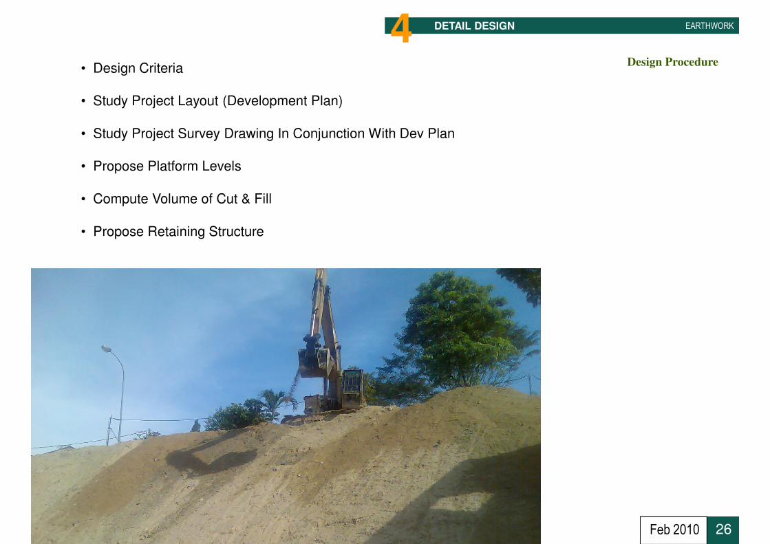
Design Procedure
EARTHWORKDETAIL DESIGN4• Design Criteria
• Study Project Layout (Development Plan)
• Study Project Survey Drawing In Conjunction With Dev Plan
• Propose Platform Levels
• Compute Volume of Cut & Fill
• Propose Retaining Structure
26Feb 2010

Design Procedure
EARTHWORKDETAIL DESIGN4
• Design Criteria
• Study Project Layout (Development Plan)
• Study Project Survey Drawing In Conjunction With Dev Plan
• Propose Platform Levels
• Compute Volume of Cut & Fill
• Propose Retaining Structure
27Feb 2010
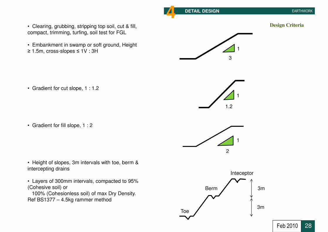
Design Criteria
EARTHWORKDETAIL DESIGN4• Clearing, grubbing, stripping top soil, cut & fill,
compact, trimming, turfing, soil test for FGL
• Embankment in swamp or soft ground, Height
≥ 1.5m, cross-slopes ≤ 1V : 3H 1
3
Sg. Balok at Coastal Road
• Gradient for cut slope, 1 : 1.2
• Gradient for fill slope, 1 : 2
1
1.2
1
2
28
• Height of slopes, 3m intervals with toe, berm &
intercepting drains
• Layers of 300mm intervals, compacted to 95%
(Cohesive soil) or
100% (Cohesionless soil) of max Dry Density.
Ref BS1377 – 4.5kg rammer method
Inteceptor
Berm
Toe
3m
3m
Feb 2010

Design Criteria
EARTHWORKDETAIL DESIGN4• All slopes closed turf
Tg Gelang
Sg. Balok at Coastal Road
• Min Formation Platform Level, 1m above
Highest Flood Level or EHW (Coastal)
• Temporary drains to main drain shall pass Silt
Trap (Sediment trap)
29
• Wash Through before public road
• Temporary drains, design for 1 in 5 years,
checked for 1 in 10 years
• Min 1 no Temporary Bench Mark established
Feb 2010

Design Criteria
EARTHWORKDETAIL DESIGN4
Sg. Balok at Coastal Road
30Feb 2010

Design Options For Cut Slopes
EARTHWORKDETAIL DESIGN4
31Feb 2010

Design Options For Fill Slopes
EARTHWORKDETAIL DESIGN4
32Feb 2010

Design Procedure
EARTHWORKDETAIL DESIGN4
• Design Criteria
• Study Project Layout (Development Plan)
• Study Project Survey Drawing In Conjunction With Dev Plan
• Propose Platform Levels
• Compute Volume of Cut & Fill
• Balancing Cut & Fill Volume
33Feb 2010
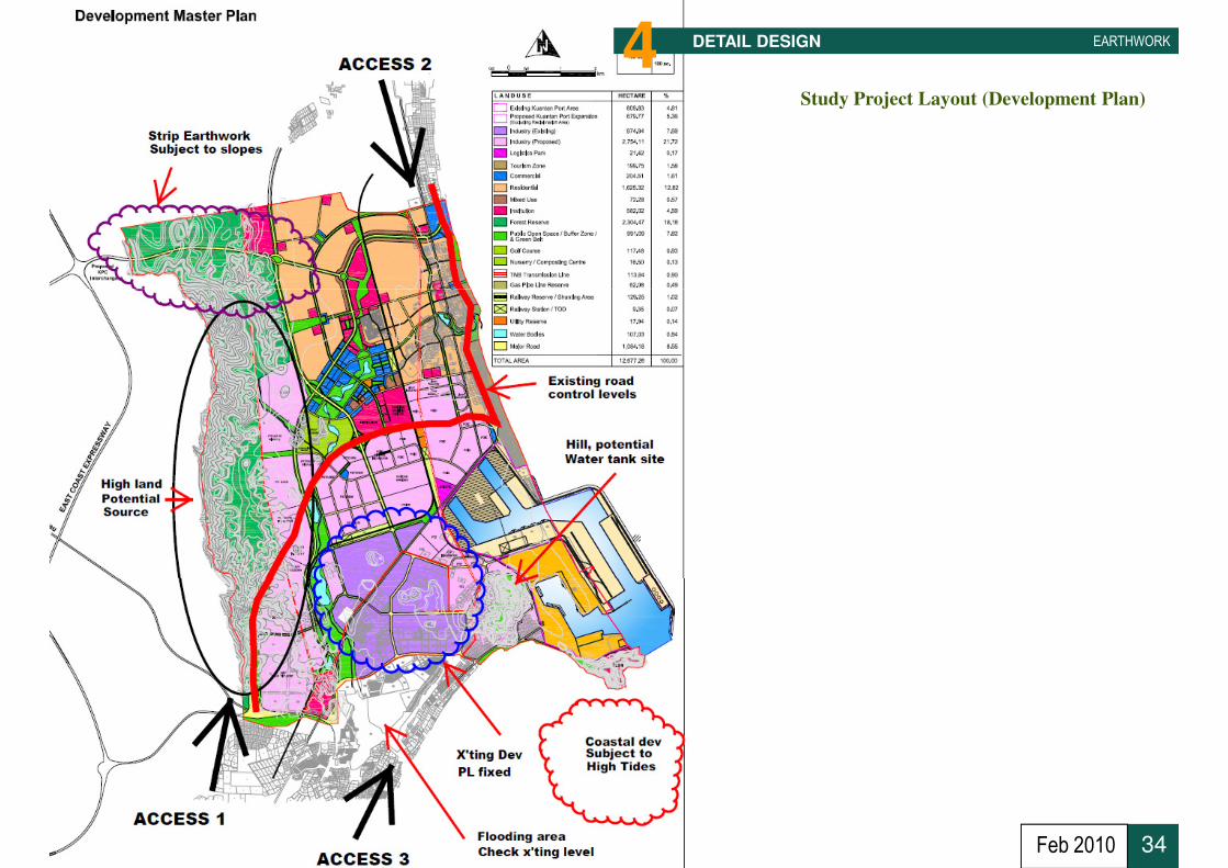
Study Project Layout (Development Plan)
EARTHWORKDETAIL DESIGN4
34Feb 2010

Assessment of Available Survey Information
EARTHWORKDETAIL DESIGN4Slopes direction
Slopes directionSwampy
Potential high
Ground for Water
Supply Tank
Swampy+2m to 3m
Hilly 80m
Existing Existing
35
Slopes direction
Existing+5m to 9m
Existing+5.5m
Existing+3m
Feb 2010

Design Procedure
EARTHWORKDETAIL DESIGN4
• Design Criteria
• Study Project Layout (Development Plan)
• Study Project Survey Drawing In
Conjunction With Dev Plan
• Propose Platform Levels
• Compute Volume of Cut & Fill
36
• Compute Volume of Cut & Fill
• Propose Retaining Structure
Feb 2010

Assessment of Available Survey Information
EARTHWORKDETAIL DESIGN4Slopes direction
Slopes directionSwampy
Fill
Potential high
Ground for Water
Supply Tank
Swampy+2m to 3m
Hilly 80m
Existing Existing
Cut
37
Slopes direction
Existing+5m to 9m
Existing+5.5m
Existing+3m
Feb 2010
Design Procedure
EARTHWORKDETAIL DESIGN4
• Design Criteria
• Study Project Layout (Development Plan)
• Study Project Survey Drawing In Conjunction With Dev Plan
• Propose Platform Levels
• Propose Retaining Structure
• Balancing Cut & Fill Volume
38Feb 2010

Assessment of Minimum Platform Level
EARTHWORKDETAIL DESIGN4
• HFL = 2.2 m ODL
• Freeboard = 1.0m
• Drainage Gradient = 1.5m
• Recommended Min. Platform Level = 4.7m ODL
Existing Platform Level at Project Site Varies from PL+5m to PL+9m
Swampy and Low Lying Level at Upstream = PL+2m to PL3m
Highest Flood Level (JPS record or ever known)
39
Freeboard = +1m
Highest Flood Level = +2.2m ODL
Water body
Proposed Platform Level Formation
Min.
Max.
Feb 2010

Conceptual Platform
EARTHWORKDETAIL DESIGN4
Platform Level to be above Highest Flood Levelbe above Highest Flood Level
40Feb 2010
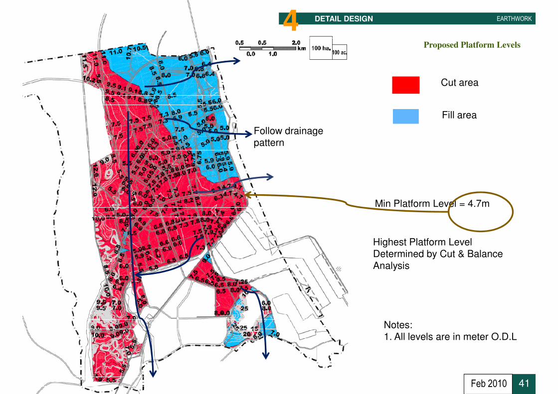
Cut area
Fill area
Follow drainage
Proposed Platform Levels
EARTHWORKDETAIL DESIGN4
• Min Platform Level = 4.7m
Follow drainagepattern
Highest Platform LevelDetermined by Cut & Balance
Analysis
41
Notes:1. All levels are in meter O.D.L
Analysis
Feb 2010
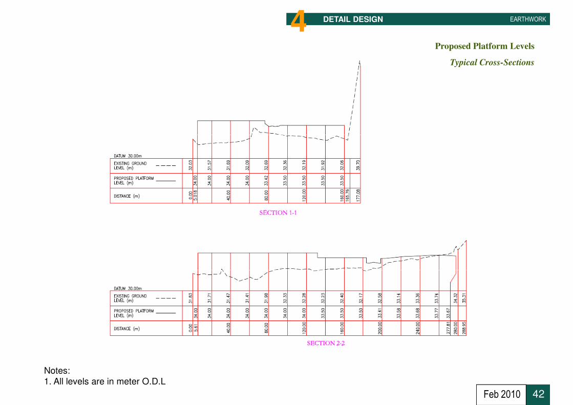
EARTHWORKDETAIL DESIGN4Proposed Platform Levels
Typical Cross-Sections
42
Notes:
1. All levels are in meter O.D.L
Feb 2010

EARTHWORKDETAIL DESIGN4Proposed Platform Levels
Typical Building Platforms
43Feb 2010

Design Procedure
EARTHWORKDETAIL DESIGN4
• Design Criteria
• Study Project Layout (Development Plan)
• Study Project Survey Drawing In Conjunction With Dev Plan
• Propose Platform Levels
• Compute Volume of Cut & Fill
• Propose Retaining Structure
44
• Propose Retaining Structure
Feb 2010
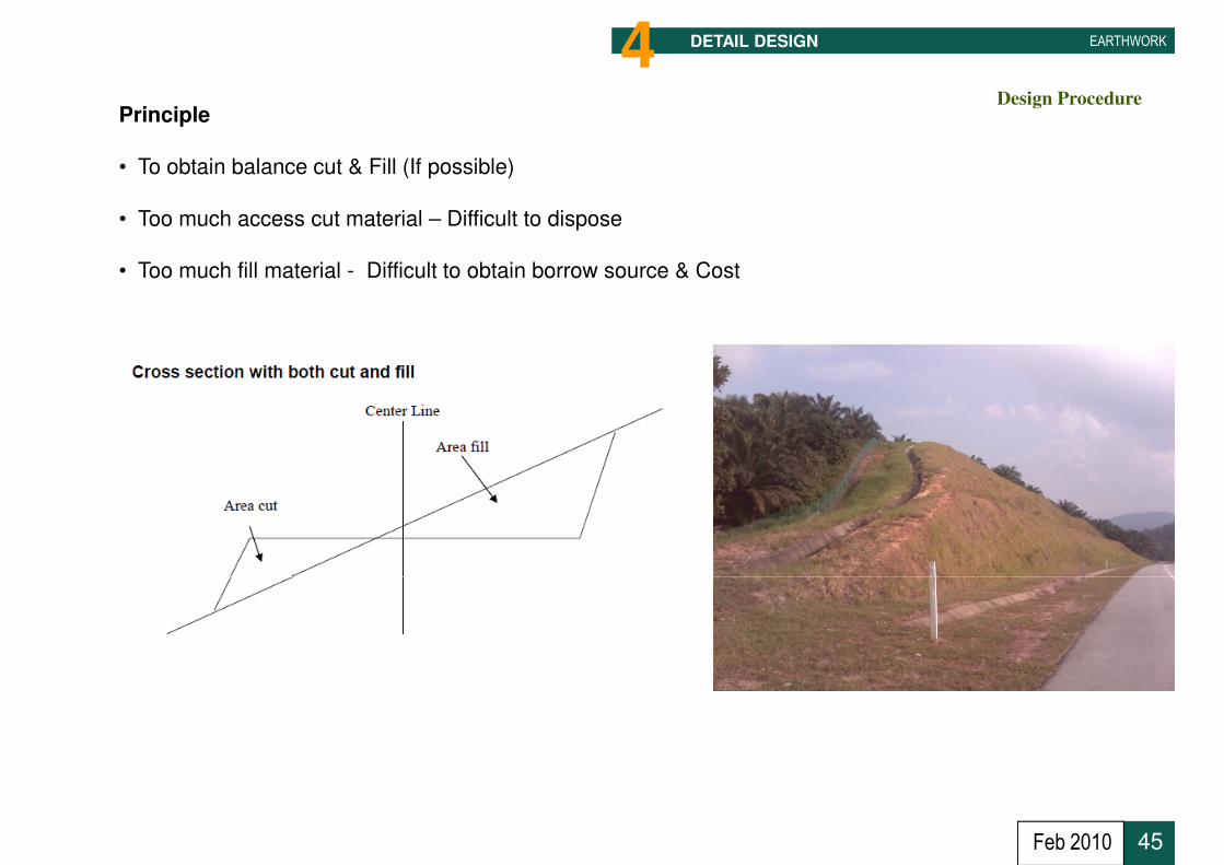
Design Procedure
EARTHWORKDETAIL DESIGN4Principle
• To obtain balance cut & Fill (If possible)
• Too much access cut material – Difficult to dispose
• Too much fill material - Difficult to obtain borrow source & Cost
45Feb 2010
Design Procedure
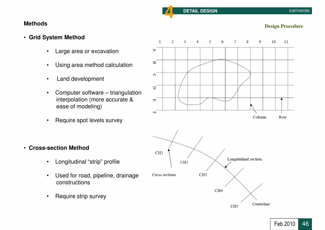
EARTHWORKDETAIL DESIGN4Methods
• Grid System Method
• Large area or excavation
• Using area method calculation
• Land development• Land development
• Computer software – triangulationinterpolation (more accurate &
ease of modeling)
• Require spot levels survey
• Cross-section Method
46
• Longitudinal “strip” profile
• Used for road, pipeline, drainage
constructions
• Require strip survey
Feb 2010

EARTHWORKDETAIL DESIGN4Proposed Platform Levels
Volume of Cut & Fill
A1 2 3 4 5 6 7 8 9 10 11 GRID SYSTEM METHOD
B
C
D
E
F
• To obtain large area of excavation
• Square rectangular and levels at
each cross-sections established
• Establish datum
• Calculate volume of existing ground
• Calculate volume of proposed platform
• Difference s constitute cut or fill volume
47
• Difference s constitute cut or fill volume
Feb 2010
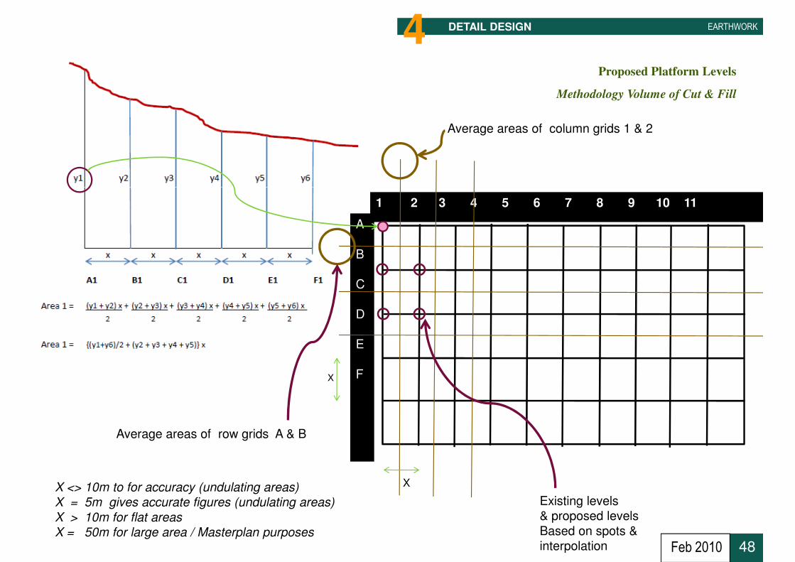
EARTHWORKDETAIL DESIGN4Proposed Platform Levels
Methodology Volume of Cut & Fill
Average areas of column grids 1 & 2
A
B
C
D
E
F
1 2 3 4 5 6 7 8 9 10 11
X
48
F
Average areas of row grids A & B
X
X
Existing levels
& proposed levels
Based on spots &
interpolation
X <> 10m to for accuracy (undulating areas)
X = 5m gives accurate figures (undulating areas)
X > 10m for flat areas
X = 50m for large area / Masterplan purposes
Feb 2010

EARTHWORKDETAIL DESIGN4Grid System
1 10 10 10 10 10 10 10 10 10 10
A E 10 10 10 8 8 5 5 3 3 3 3 2 2 2 2 3 3 3
P 7.5 7.5 7.5 7.5 7.5 7.5 7.5 6 6 5 5 5 5 5 5 5 5 5
10 C 250 175 0 0 0 0 0 0 0
F 0 0 0 -212.5 -275 -275 -300 -250 -200
P 7.5 7.5 7.5 7.5 7.5 5 5 6 6 6 6 5 5 5 5 5 5 5
E 10 10 10 9 9 5 5 3 3 3 3 2 2 2 2 3 3 3
E 10 10 10 9 9 5 5 3 3 3 3 2 2 2 2 3 3 3
P 7.5 7.5 7.5 7.5 7.5 5 5 6 6 6 6 5 5 5 5 5 5 5
10 C 325 300 212.5 0 0 0 0 0 0
F 0 0 0 -25 -250 -250 -247.5 -245 -195
P 6 6 6 6 6 6 6 6 6 6 6 6 6 5.9 5.9 5.9 5.9 5.9
2 3 4 5 8 9
B
6 7
LegendP 6 6 6 6 6 6 6 6 6 6 6 6 6 5.9 5.9 5.9 5.9 5.9
E 10 10 10 10 10 9 9 5 5 3 3 5 5 3 3 4 4 4
E 10 10 19 10 10 9 9 5 5 3 3 5 5 3 3 4 4 4
P 6 6 6 6 6 6 6 6 6 6 6 7 7 5.9 5.9 5.9 5.9 5.9
10 C 325 500 225 50 0 0 0 0 0
F 0 0 0 0 -150 -150 -115 -105 -80
P 6 6 6 6 6 6 6 6 6 6 6 5 5 4.7 4.7 4.7 4.7 4.7
E 9 8 8 7 7 7 7 5 5 5 5 5 5 5 5 5 5 5
E 9 8 8 7 7 7 7 5 5 5 5 5 5 5 5 5 5 5
P 6 6 6 6 6 6 6 6 6 6 6 6 6 4.7 4.7 4.7 4.7 4.7
10 C 250 162.5 137.5 75 25 0 0 30 30
F 0 0 0 0 0 0 -10 0 0
P 6 6 6 6 6 6 6 6 6 5 5 5 5 4.7 4.7 4.7 4.7 4.7
E 9 8 8 7.5 7.5 8 8 7 7 7 7 5 5 5 5 5 5 5
E 9 8 8 7.5 7.5 8 8 7 7 7 7 5 5 5 5 5 5 5
P 6 6 6 6 6 6 6 6 6 5 5 5 5 4.7 4.7 4.7 4.7 4.7
10 C 225 162.5 137.5 137.5 162.5 100 15 30 30
F 0 0 0 0 0 0 0 0 0
E
C
D
Legend
E Existing
P Proposed
C Cut
F Fill
49
Proposed Platform Levels
Volume of Cut & Fill
F 0 0 0 0 0 0 0 0 0
P 6 6 6 6 6 6 6 5.5 5.5 5 5 5 5 4.7 4.7 4.7 4.7 4.7
F E 8 8 8 7 7 7 7 7 7 7 7 5 5 5 5 5 5 5
All dimensions are in meters Total Area = Acres
Total Cut = CuM
Spoil @ 20% = CuM
Available Fill = CuM
Total Fill = CuM
To import Fill = CuM
Access Cut = CuMNil
50.02
4,072.50
814.50
3,258.00
3,335.00
77.00
Feb 2010
Design Procedure
EARTHWORKDETAIL DESIGN4
• Design Criteria
• Study Project Layout (Development Plan)
• Study Project Survey Drawing In Conjunction With Dev Plan
• Propose Platform Levels
• Compute Volume of Cut & Fill
• Propose Retaining Structure
50Feb 2010

Design Procedure
EARTHWORKDETAIL DESIGN4Earth Retaining Structure
Standards Used in Design
51Feb 2010
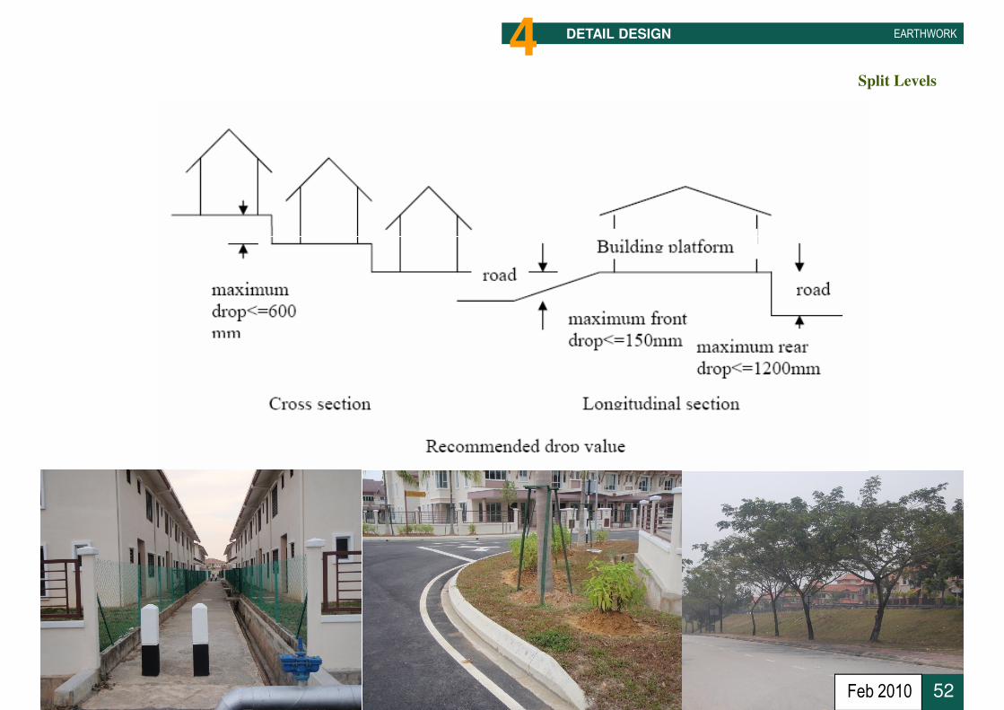
Split Levels
EARTHWORKDETAIL DESIGN4
52Feb 2010

Earth Retaining Structure
EARTHWORKDETAIL DESIGN4
53Feb 2010
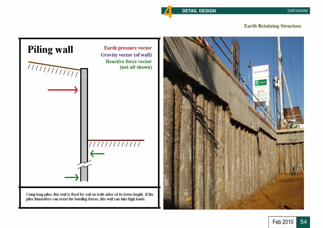
Earth Retaining Structure
EARTHWORKDETAIL DESIGN4
54Feb 2010
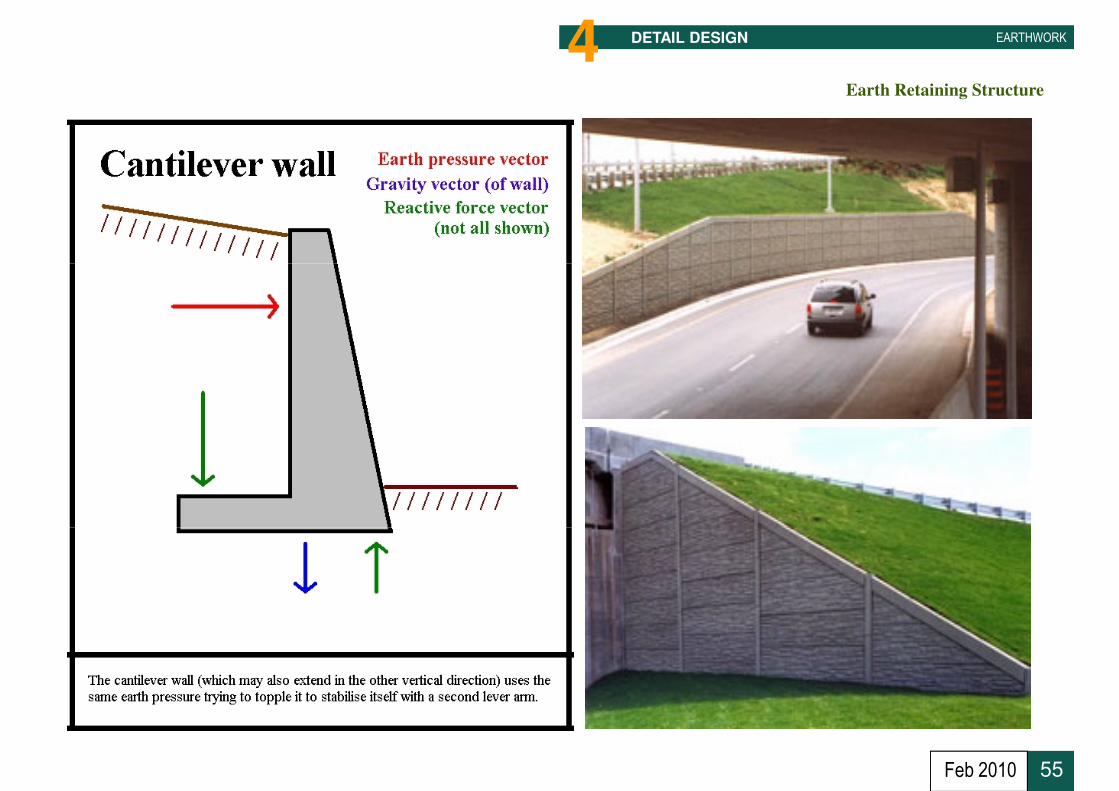
Earth Retaining Structure
EARTHWORKDETAIL DESIGN4
55Feb 2010
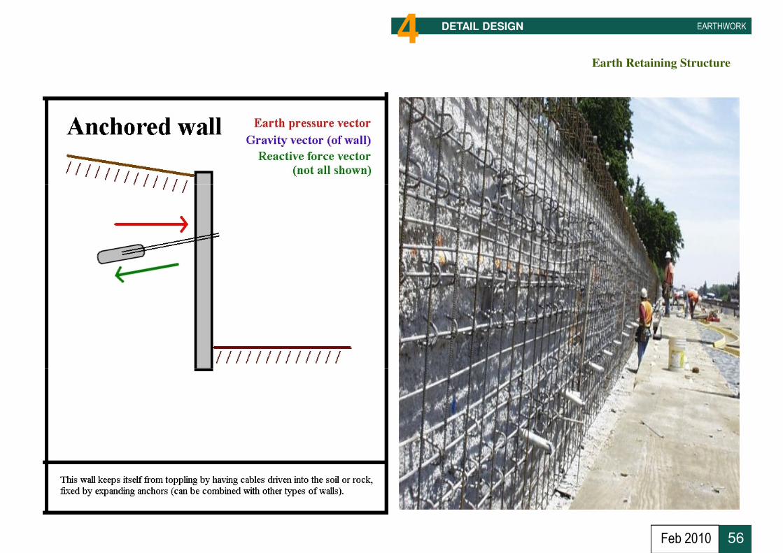
Earth Retaining Structure
EARTHWORKDETAIL DESIGN4
56Feb 2010

Earth Retaining Structure – Typical Detail
EARTHWORKDETAIL DESIGN4
57Feb 2010

EARTHWORK
55 Authority
Compliance & Approvals
58Feb 2010

Governing Law
EARTHWORKAUTHORITY Compliance & Approvals5
Earthworks regulation and approval is under the jurisdiction of Local Council.Earthworks regulation and approval is under the jurisdiction of Local Council.
59Feb 2010
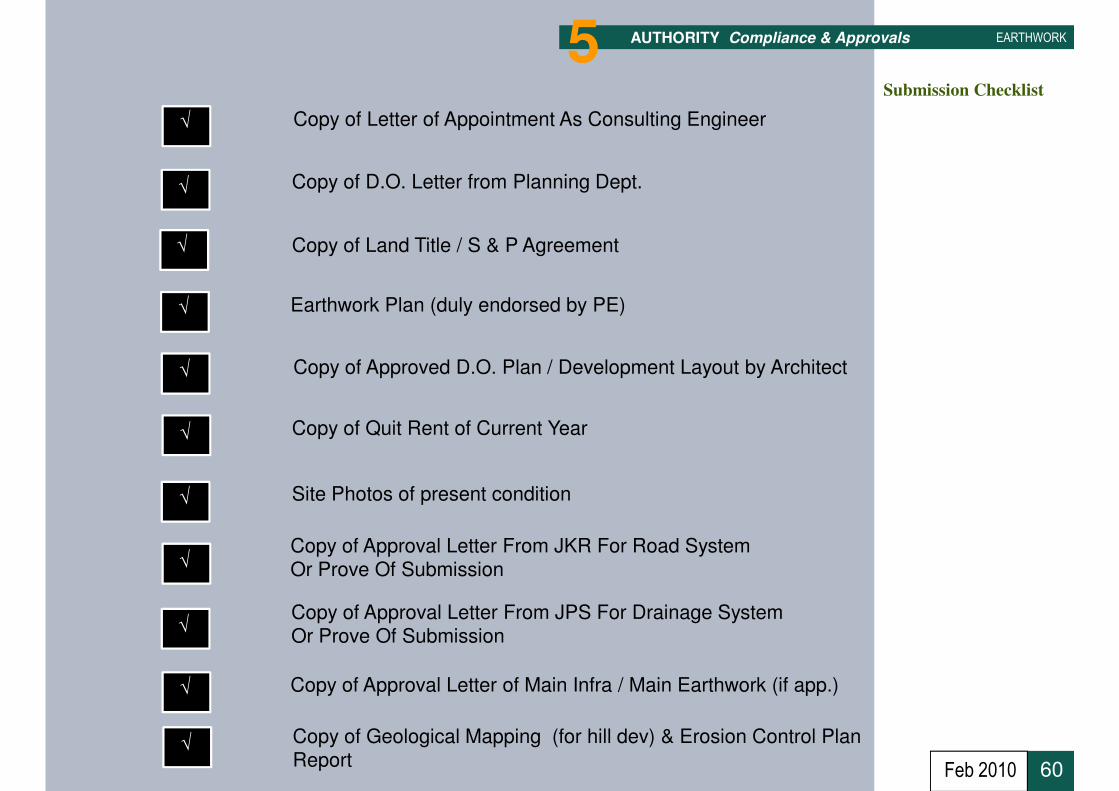
Submission Checklist
√
√
√
Copy of Letter of Appointment As Consulting Engineer
Copy of D.O. Letter from Planning Dept.
Copy of Land Title / S & P Agreement
EARTHWORK5 AUTHORITY Compliance & Approvals
√
√
√
√
Earthwork Plan (duly endorsed by PE)
Copy of Approved D.O. Plan / Development Layout by Architect
Copy of Quit Rent of Current Year
Site Photos of present condition
60
√
√
√
√
Copy of Approval Letter From JKR For Road SystemOr Prove Of Submission
Copy of Approval Letter From JPS For Drainage SystemOr Prove Of Submission
Copy of Approval Letter of Main Infra / Main Earthwork (if app.)
Copy of Geological Mapping (for hill dev) & Erosion Control Plan Report
Feb 2010

Submission Process Flow
EARTHWORK5
SUBMITTING PERSON
No
AUTHORITY Compliance & Approvals
JPS
JKR
Approval
No
Yes
61
PTG
LC
OSC One Stop Centre
Feb 2010

EARTHWORK
66 Construction
62Feb 2010
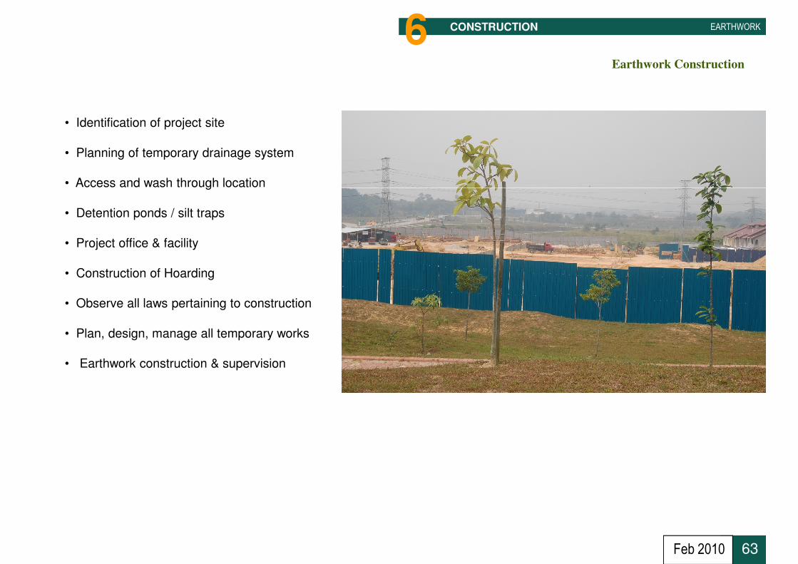
Earthwork Construction
EARTHWORK6 CONSTRUCTION
• Identification of project site
• Planning of temporary drainage system
• Access and wash through location• Access and wash through location
• Detention ponds / silt traps
• Project office & facility
• Construction of Hoarding
• Observe all laws pertaining to construction
• Plan, design, manage all temporary works
• Earthwork construction & supervision
63Feb 2010

Earthwork Construction
EARTHWORK6 CONSTRUCTION
• Review costruction
programme
• Control & Monitor• Control & Monitor
64Feb 2010
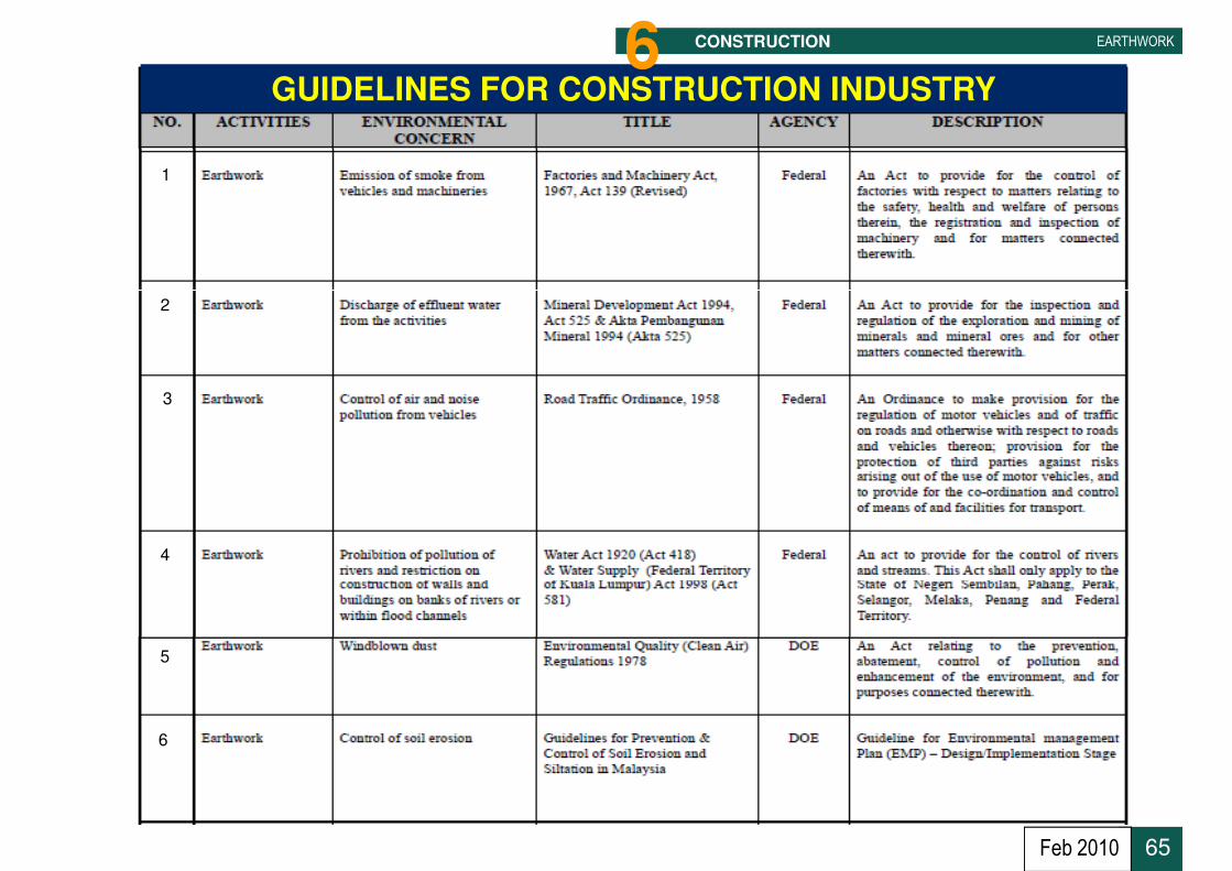
GUIDELINES FOR CONSTRUCTION INDUSTRY
1
EARTHWORKCONSTRUCTION6
2
3
4
5
6
65Feb 2010

Quality Control
EARTHWORK6 CONSTRUCTION
• General Instruction
• Construction Drawings
• Specifications Contract Document
• Bills of Quantities
• Compliance to Authority’s requirement
Site Supervision to comply ;
• Compaction 95% max of dry density @ BS 1377
Building footprints, roads & services corridor, runways, etc
• Compaction 75%
Building footprints but to allow Suspended Floor slab design
Area not subject to buildings construction i.e fields, landscape, etc
• Each layer ≤ 200mm thick
66
• For road sub-base, soaked CBR value ≥ 30 for 95% consolidation
Feb 2010

Soil Compaction
EARTHWORK6 CONSTRUCTION
Selection of types of compaction machinery Vs types of soil
67
Grid roller
Sheepsfoot rollerSmooth wheeled roller
Feb 2010

EARTHWORK6 CONSTRUCTION
July 2009 68Site Clearing Work
68Feb 2010

EARTHWORK6 CONSTRUCTION
69
In-land Development
Feb 2010

EARTHWORK6 CONSTRUCTION
Low Land Earthwork Platforming
70Feb 2010

EARTHWORK6 CONSTRUCTION
Mandatory Hoarding
71Feb 2010

EARTHWORK6 CONSTRUCTION
Installation of Mandatory Paver Blocks at Entrance of Construction Site
72Feb 2010
EARTHWORK6 CONSTRUCTION
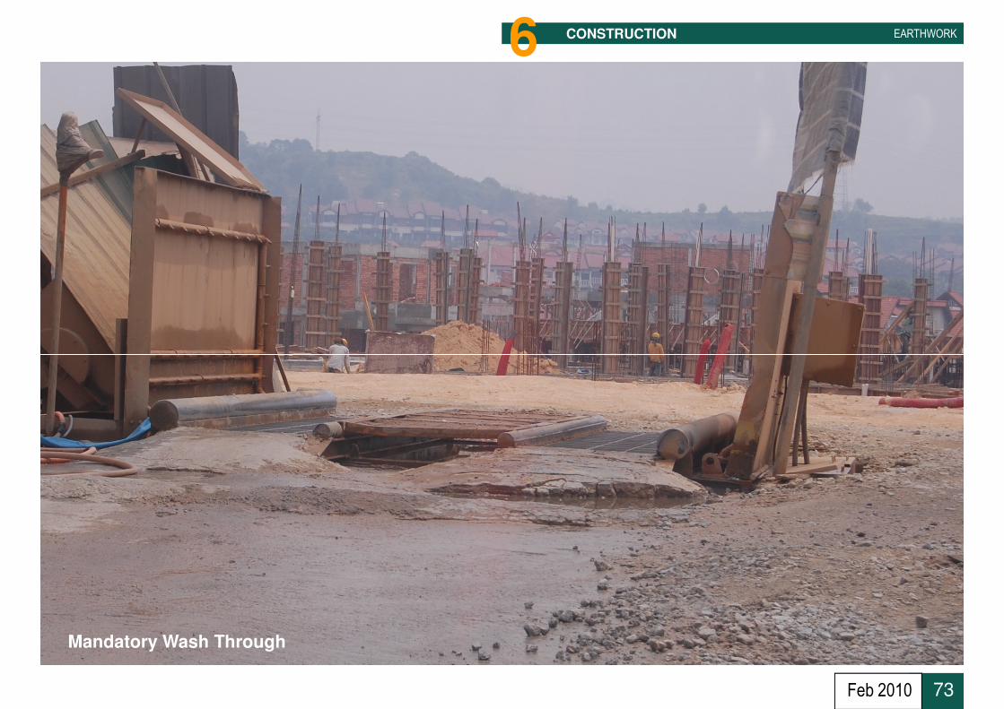
Mandatory Wash Through
73Feb 2010

EARTHWORK6 CONSTRUCTION
Installation of Geosynthetic Materials For Earthwork in Soft Ground
74Feb 2010

EARTHWORK6 CONSTRUCTION
Cut Slopes Formation With Closed Turf
75Feb 2010

EARTHWORK6 CONSTRUCTION
76
76
Installation of Geomembrane to prevent ground contamination @ solid waste disposal
Feb 2010

EARTHWORK6 CONSTRUCTION
Urban Construction - Completed Earthwork Being CloseTurfed – Final Stage
77Feb 2010

EARTHWORK
77 Post - Construction
78Feb 2010

Inspection & As-Built Documents
EARTHWORK7 POST - CONSTRUCTION
• Engineer to carry out confirmatory Soil Investigation to verify full compliance i.e. Compaction, Soil Stabilization, etc.
• Land Surveyor to survey As-Built earthworks platforms to verify full • Land Surveyor to survey As-Built earthworks platforms to verify full
compliance pertaining to FGL or PL.
• Land Surveyor & Engineer to certify As-Built survey drawings
• Engineer Review Construction Drawings & Correct to As-Built Drawings
• Engineer updating As-Built information not covered i.e. Authority’s requirement not spelt out in Construction Drawings, V.O.
• Engineer to ensure all mandatory dues to Authority are complied
79
• Engineer arranged mandatory inspections with JPS, JKR, LC, etcto facilitate handing over works & recommendation for CCC
Feb 2010

CCC Process Flow
EARTHWORK7 POST - CONSTRUCTION
SUBMITTING PERSON (SP)
No
JPS
JKR
Recommendation
No
Yes
80
PTG
LCPSP Issue CCC
Feb 2010
PSP Principal Submitting Person

Post - CCC
EARTHWORK7 POST - CONSTRUCTION
• Issue Certificate Of Completion & Compliance
• Defects Liability Period. Generally 1 to 1.5 years
• Issue Certificate of Completion After Defects• Issue Certificate of Completion After Defects
• Final Account
• Total Completion of Project
81Feb 2010

Thank You
Terima Kasih
82July 2009

Questions & Answers
83July 2009