u.j ay - dtic · weld cross sections were extracted from selected weld specimens for verification...
TRANSCRIPT

•• TECHNICAL REPORT NO. 11891
Ji'l REFERENCE RADIOGRAPHS FOR FULLSi} PENETRATION ALUMINUM WELDMENTS
JUNE 1974
"" by MELVIN ,,PYHTIrA. WALTER •,,WULF
] • Approved for Public release;
• distribution unlimited.
t-VEHICULAR COMPONENTS & MATERIALS LABORATORY
U.j 3 AY
Ask2
TECHNICAL REPORT NO. 11891
REFERENCE RADIOGRAPHS FOR FULLPENETRATION ALUMINUM WELDMENTS
* BYWALTER F. WULFM4ELVIN V. PYHTILA
,JUNE 1974
AMCMS CODE 5393-OM-6350
ARMOR, MATERIALS & COMPONENTS DIVISION

ABSTRACT
Standard reference radiographs were selected fromweld flaw specimens fabricated from aluminum plate ofvarious thicknesses to establish a military documentcontaining reference radiographs for quality control offull penetration aluminum weldments. The various typesof flaws known to occur in full penetration aluminum weldswere prepared with production reproducible welding procedures,and were radiographically graded according to pre-establishedseverity levels.
S~iii
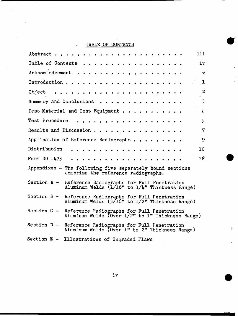
TABLE OF CONTENTS o
Abstract .iii ... 00000
Table of Contents . .... . . . *. .. iv
Acknowledgement ........ . . . . . . . . . . . v
Introduction . . . . . . . . . ... o1
Object 0 12
Summary and Conclusions •o• S * . . . e o • * 3
Test Material and Test Equipment . . . . . . . . . . . 4
Test Procedure • •• •• .• e.. ... • • • • • 5
Results and Discussion . .. . . .0 . . . .0 . . . . . . 7
Application of Reference Radiographs . . . . . . . . o 9
Distribution . * . . . . . . . .. .. . 10
Form DD 1473 .. . . .. . .& . . . . . . . . 018
Appendixes - The following five separately bound sectionscomprise the reference radiographs.
Section A - Reference Radio graphs for Full PenetrationAluminum Welds (71/6" to 1/4" Thickness Range)
Section B- Reference Radiogra hs for Full PenetrationAluminum Welds (3/16" to 1/2" Thickness Range)
Section C - Reference Radio graphs for Full PenetrationAluminum Welds (Over 1/2" to 1" Thickness Range)
Section D - Reference Radiographs for Full PenetrationAluminum Welds (Over 1" to 2" Thickness Range)
Section E - Illustrations of Ungraded Flaws
iv

ACKNOWLEDGEMENT
Appreciation is expressed for the excellent weldingservice furnished by personnel of the Armor Function andExperimental Division. Through their technical proficiency,the difficult task of achieving the designated weld flawtypes and quality levels was accomplished at an unprecedented501 efficiency factor.
This project has been accomplished as part of the USArmy Materials Testing Technology Program, which has for itsobjective the timely establishment of testing techniques,procedures or prototype equipment (in mechanical, chemical,or nondestructive testing) to insure efficient inspectionmethods for materiel/material procured or maintained by AMC.
V

INTRODUCTION
The increasing use of aluminum in the fabricationof military hardware has brought into focus the need fora document to provide universal quality control for fullpenetration aluminum weldments.
In accordance with project authorization from ArmyMaterials and Mechanics Research Center, this task wasestablished under the Materials Testing Technology Program.The effort was determined necessary since there are nostandard reference radiographs presently available for fullpenetration aluminum welds in the thickness ranges requiredfor Army application.
10
3-Q

OBJECTIVE
Establish standard reference radiographs for fullpenetration aluminum weldments ranging in thickness from1/16 inch to'inches.
Q'
÷2

SUMMARY AND CONCLUSIONS or
Standard reference radiographs displaying graded andungraded illustrations of flaws found in full penetrationaluminum weldments were established. Completion of thedocument provides the means for establishing universalquality assurance standards for military hardware containingfull penetration aluminum welds.
3

TEST MATERIAL
1. Wrought aluminum alloy plates, types 6061 and5083, 1/8", 3/16", 3/8", 3/4" and 1-1/2" thick.
2. Electrode wire of varying sizes for the MIG andTIG welding process of aluminum.
3. Argon shielding gas, welding grade, 99% pure(TIG).
4. Argon shielding gas, welding grade with 1% oxygenadded (MIG).
5. Industrial X-ray film, size 4-1/2 x 17", fine grain.
6. Commercial photographic copy film, size 4 x 5".
7. Photographic projection print paper.
5 • TEST EQUIPMENT
1. Constant-arc voltage rectifier power source, 500ampere capacity, for the inert gas consummable electrode weld-ing process.
2. An AC-DC, 300 amp, power source for the inert gastungsten arc welding process.
3. Industrial X-ray machine, 250 KVP, 10 MA capacity.
4. Commercial, 4 x 5", view camera.
5. Commercial, 4 x 5", condenser type photographicenlarger.
A1

Section A(1/16" to 1/4" Thickness Range)
± /6 1/6 -"
SectionB (3/16" to 1/2" Thickness Range)
-75T
ICI0
+1rTO ~
Section C (Over 1/2" to 1" Thickness Range)
750 -] O75 oS/I -r• . __h•+ -F--I .- OroI
WELD JOINT DESIGNS USED ON FLAW SPECIMEN PLATES
Figure 1

SectionD(Over 1" to 2" Thickness Range)
ici°
CO~ro 75,
WELD JOINT DESIGNS USED ON FLAW SPECIMEN PLATES
O Figure 2

TEST PROCEDURE
1. Weld Plate Preparation:
Plate size and thickness used for each of the fourthickness ranges are as follows:
MasterThickness Plate PlateRange Thickness Size
Section A 1/16" to 1/4" 1/8" & 3/16" 6" x 15"
Section B 3/16" to 1/2" 3/8" 6" X 24"
Section C Over 1/2" to 3/4" 8" x 30"1i"
Section D Over 1" to 2" 1-1/2" 10" x 30"
Edge preparation for the weld groove was accomplished bysawing and hand grinding. A few plates requiring a moreprecise fit were machined. Joint designs used for each weld Sthickness range are illustrated on Figures 1 and 2.
2. Welding Procedure:
Two welding processes were employed. The gas tungstenarc (TIG) process was used on the 1/8" and 3/16" platescomprising Section A. These plates cover the thickness rangefrom 1/16 to 1/4 inch. The gas Metal Arc (MIG) process wasused on the remaining plates.
3. Radiographic Examination
Radiography of the weld plates was performed in accordancewith MIL-STD-453. A minimum quality level of 2 - 1T,representing 1.4% sensitivity was maintained for all exposures.The following radiographic technique was employed for thevarious size plates.
5

Plate Approx.Thick- Filmness KV MAS FFD SCREENS DENSITY
1/8 in 80 150 36 in. None 2.0
3/16 in. 80 180 36 in. None 2.0
3/8 in. 80 325 36 in. None 2.0
3/4 in. 100 700 48 in. None 2.0
1-1/2 in. 156 550 48 in. .005" 2.0
4. Metallographic Evaluation:
Weld cross sections were extracted from selected weldspecimens for verification of radiographic findings.Photomacrographs were also made of typical flaw conditionsfor correlation with the reference radiographs.
5. Selection of Reference Radiographs:
Selection and grading of the radiographs was based on;(a) correlation of current USATACOM standards for partialpenetration weldments (ATAC - STD-113 and 114), (b) Weldresearch programs conducted at USATACOM, and (c) Productionwelding problems experienced by government contractors.
6. Reproduction of Radiographs:
The original radiographs were photographically reproduced,utilizing a 4 x 5 inch view camera to copy the radiographicimage as viewed with a flurescent illuminator. Projectionprints were then made from the copy negatives and assembledinto a photo composite for each page of the document. Finallithographic reproductions were then made from the photographiccomposites.
6

RkýULTS, AND DISCUSSION
1. The primary objective of this effort was production ofthe standard reference radiographs. These are included aspart of the report in five separately bound sections.Separate binding was performed to provide greater flexibility,and to accommodate later conversion of the document to eithera TACOM or Military Standard.
2. Lithograph reproductions were selected for the finalprinting rather than film transparencies or photographicprints. Thi's was clone primarily to reduce cost and provideease of application. When proper controls are exercised,lithographs will display 90% or more of the original printdetail which is adequate for reference radiographs. Thecapability of viewing the radiographs with reflected lightalso permits wider use of the document by concerned engineering personnel that do not have X-ray viewing equipment.
3. Welding procedures used to produce the various flaws werefor the most part those that could accidently*be performedin production. Following are the procedures found mosteffective for the flaws illustrated:
a. Scattered Porosity:
Water contamination of the shielding gas using the MIGprocess proved most successful on the 3/4" and 1-1/2" thickweld specimens. On the 1/8", 3/16" and 3/8", contaminationof the joint face proved successful.
b. Linear Porosity:
This type of flaw occurs in full penetration aluminumplates as a result of entraped gas emanating from the root areaThe severity level varies depending on the cleanliness of jointinterfaces and joint fit. The method used to produce thereference radiographs was by contaminating the root area ofthe joint.
7

c. Clustered Porosity:
On the 3/4 in. and 1-1/2 in. thick weld specimens,this flaw was achieved by intermittently distubing theshielding gas with an air draft. On the 1/8 in., 3/16 in.and 3/8 in. thick weld specimens, the condition was obtainedby contaminating selected areas on the joint interface withsmall amounts of oil and paint.
d. Tungsten Inclusions:
This condition occurs only with the TIG weldingprocess. It usually happens when the tungsten electrode isaccidently inserted into the molten weld puddle during thewelding operation.
e. Incomplete Penetration:
Most of the illustrations shown were achieved byreducing the welding current. This condition can alsoresult from an improper gun position during the weldoperation.
f. Lack of Fusion:
Most frequently this flaw is associated withincomplete penetration on aluminum weldments. It resultsfrom molten metal flowing beyond the point of penetrationand filling most of the weld groove without fusing withthe side walls. Unfortunately, however, it is oftendifficult to detect radiographically due to radiationangle problems. It is, therefore, considered as anintegral part of incomplete penetration, and judgedaccordingly.

APPLICATION OF REFERENCE RADIOGRAPHS
1. The reference standards are a collection of radiographsillustrating types and degrees of weld flaws experienced infull penetration aluminum weldments. They are not qualitylevel acceptance requirements; designation of requiredacceptable quality level should be made from the referenceradiographs by the design agency.
2. The standards are intended to cover a weld thicknessrange from 1/16 to 2 inches. This may be extended to 3 inches,if applicable, at the discretion of the design agency.
3. Grading of the standards was based on correlation ofexisting specifications, welding research programs, andliaison with private industry. Standard 1 represents thehighest quality normally expected in production weldingwhich contains a few flaws to reserve a rating of "sound"for special applications. Standard 5 is designated as thelowest quality welds ever accepted in production welding.The intermediate standards are divided proportionally between1 and 5.
4. Acceptance standards may be selected directly from oneof five reference radiographs for all flaws illustratedexcept clustered porosity and incomplete penetration. Rulesgoverning the standards for these flaws are specified on theappropriate illustrations in each section.
5. When only one type of flaw is present in the radiographand is less severe than the specified quality level, theweld shall be regarded as radiographically acceptable. Ifthe radiograph shows a flaw of greater severity than specified,the weld shall be rejected unless repair is permitted.
6. When two or more types of flaws are present in the sameradiograph, the predominating flaw, if unacceptable, shallgovern without regard to the other types of flaws.
7. When two or more types of flaws are present to an extentequal to that of the specified standard, the weld shall bejudged unacceptable unless repair is permitted.
9

DISTRIBUTION LIST
ADDRESSEE NO. OFCOPIES
Defense Metals Information Center,Battelle Memorial Institute, 505 King Avenue.Columbus, Ohio 43201 2
CommanderDefense Documentation Center,Cameron Station
.Alexandria, Virginia 22314 12
Commander, U. S. Army Foreign Science and Tech-nology CenterATTN: AMXST-SD3,220 Seventh Street NECharlottesville, Virginia 22901 1
Office of Chief of Research and DevelopmentDepartment of the ArmyWashington, DC 20310ATTN: DARD-ARS-P 1
CommanderArmy Research OfficeATTN: Dr. H. M. Davis 1
Mr. J. J. Murray 1Box CM, Duke StationDurham, North Carolina 27706
CommanderU. S. Army Materiel CommandATTN: AMCQA-V 1
AMCQA-E 1AMCQA-P 1AMCRD-TC 1AMCDL 1AMCRD-EA 1AMCRD-U 1
Alexandria, Virginia 22304
CommanderU. S. Army Electronics CommandATTN: AMSEL-PA-P 1
AMSEL-CT-DT 1AMSEL-WL-DO 1AMSEL-VL-D 1AMSEL-RD-EA 1
Fort Monmouth, New Jersey 07703
10

No. offCopies
Commander Copies
U. S. Army Missile CommandATTN: AMSMI-RP, Redstone Scientific Info Center 2
AMSMI-M 1AMSMI-Q, Mr. Robert 0. Black 1AMSMI-QS, Mr. George L. Stewart, Jr. 1AMSMI-QSD, Mr. Leslie Conger 1
Redstone Arsenal, Alabama 35809
CommanderU. S. Army Troop Support CommandATTN: AMSTS-QR 1
AMSTS-M 1AMSTS-P 1AMSTS-R 1
4300 Goodfellow BlvdSt. Louis, Missouri 63120
CommanderU. S. Army Natick LaboratoriesATTN: STSNLT-EQR i
STSNLT-GE 1Kansas StreetNatick Massachusetts
CommanderU. S. Army Mobility Equipment Research &Development Center 2ATTN: STSFB-E 1
STSFB-M 1STSFB-MM 1STSFB-X 1STSFB-D 1STSFB-DO 1STSFB-O 1STSFB-J 1STSFB-W 1
Fort Belvoir, VA 22060
.DirectorUSA Mobility Equipment Research & DevelopmentCenter, Coating and Chemical LabATTN: STSFB-CL 1Aberdeen Proving Ground, MD 21005
1-1

NO. OF
Commander COPIES
US Army Tank Automotive CommandATTN: AMSTA-RKMD, Mr. J. Duzinski 1
AMSTA-RKAB, Mr. W. Wulf 1AMSTA-RHP, Mr. 0. Renius 1AMSTA-QE, MR. P. Duika 5AMSTA-RWL 1AMSTA-RE 1
28251 Van Dyke AvenueWarren, MI 48090
CommanderU. S. Army Armament Command 2ATTN: AMSAR-QA 1
AMSAR-SC 1AMSAR-RDP 1AMSAR-EN 1
Rock Island, IL 61201
CommanderEdgewood ArsenalATTN: SAREA-TS-A 1
SAREA-PA 1SAREA-PA-Q 1SAREA-PA-T 1
Aberdeen Proving Ground, MD 21010
Commander, Frankford ArsenalATTN: SARFA-A2000 1
SARFA-F6000 2SARFA-P3000 1SARFA-KIO00 2SARFA-Q1000 2SARFA-NIO00 1SARFA-N7100, Mr. Mondress 1SARFA-JIO00 1
Philadelphia, PA 19137
Commander, Pictinny ArsenalATTN: SARPA-TS-S, Mr. M. Costello,) 1
SARPA-FR-P, Mr. H. DeFazio 1SARPA-FR-S, Mr. T. M. Roach, Jr. 1SARPA-FR-G, Mr. A. J. Clear 1SARPA-QA-T, Mr. D. Stein 1SARPA-FR-M, Mr. W. Powers 1
Dover, New Jersey, 07801
12

Commander, Rock Island ArsenalATTN: 9320, Research and Development 1
SARRI-LEQ, MR. J. Hausman 1SARRI-LER, Mr. W. Kisner 2SARRI-Q, Mr. W. Betts 1SARRI-RS, Mr. V. Long 1SARRI-R, Mr. W. McHenry 1
Rock Island, IL 61201
Commander, Watervliet Arsenal 2ATTN: SARWV-PPI, Mr. L. A. Jette 1
SARWV-RDS, Mr. M. L. Slawsky 1SARWV-RDR, Dr. F. W. Scheideshoff 1SARWV-QA, Mr. J. J. Miller 1SARWV-QA, Quality Assurance Directorate 1
Watervliet, New York, 12189
CommanderU. S. Army Tropic Test CenterATTN: STETC-XO-A, Drawer 942Ft. Clayton, CZ 1
Commander, Aberdeen Proving GroundATTN: STEAP-MT 1
STEAP-TL 1STEAP-MT-M, Mr. J. A. Feroli 1STEAP-MT-G, Mr. R. L. Huddleston 1
Aberdeen Proving Ground, Maryland 21005
CommanderU. S. Army Arctic Test CenterATTN: STEAC-MO-ASAPO Seattle 98733 1
Commander,Dugway Proving GroundATTN: STEPD-TO(D),Utah 84022 1
CommanderU. S. Army Electronic Proving GroundATTN: STEEP-MTFt. Huachuea, AZ 8561 1
CommanderJefferson Proving GroundATTN: STEUP-TD-IMadison, IN 47250 1
113-

CommanderU. S. Army Aviation Systems CommandATTN: AMSAV-EE 1
AMSAV-EEG 1AMSAV-FEE 1AMSAV-LE 1AMSAV-LEP 1AMSAV-LSA 1AMSAV-PV 1AMSAV-EFS 1
St. Louis, MO 63166
CommanderU. S. Army Aeronautical Depot Maintenance Center(Mail Stop 55), Attn: AMSAV-FES, Mr. Bee,Corpus Christi, TX 78419 1
DirectorU. S. Army Production Equipment AgencyATTN: AMXPE-MTRock Island ArsenalRock Island, IL 61201 1
CommanderHarry Diamond LaboratoriesATTN: AMXDO-EDEConnecticut Avenue & Van Ness Street, NWWashington, DC 20438 2
CommanderU. S. Army Test & Evaluation CommandATTN: AMSTE-RA,Aberdeen Proving Ground, Maryland 21005 1
Commander, U. S. Army White Sands Missile RangeWSMR, NM 88002ATTN: STES-AD-L 1
STEWS-ID-P 1
CommanderU. S. Army Yuma Proving GroundATTN: STEYP-MTS 1
STEYP-ADT 1Yuma, AZ 85364
014

PresidentU. S. Army Airborne, Communications & ElectronicsBoardATTN: STEBF-TDFt. Bragg, NC 28307
PresidentU. S. Army Air Defense BoardATTN: STEBD-TDFt. Bliss, TX 79916
PresidentU. S. Army Armor & Engineer BoardATTN: STEBB-TDFt. Knox, KY 40121
PresidentU. S. Army Aviation Test BoardATTN: STEBG-MTFt. Rucker, AL 36360
PresidentU. S. Army Field Artillery BoardATTN: STEBA-TDFt. Sill, OK 73503
PresidentU. S. Army Infantry BoardATTN: STEBC-TEFt. Benning, GA 319051
CommanderAnniston Army DepotATTN: AMXAN-QAAnniston, Alabama 36202
CommanderLetterkenny Army DepotATTN: AMXLE'QAChambersburg, PA 12701
CommanderLexington-Bluegrass Army DepotATTN: AMXLX-QALexington, KY 40507
1-5

Commander
New Cumberland Amy DepotATTN: AMXNC-QANew Cumberland, PA 17070
Commander-Pueblo Army Depot,ATTN: AMXPU-QPueblo, Colorado 81001 2
CommanderRed River Amy DepotATTN: AMXRR-QATexarkana, TX 75501 1
CommanderSacremento Army DepotATTN: AMXSA-QASacramento, CA 950l 1
CommanderSavanna Army DepotATTN: AMXSV-QASavanna, IL 61074 1
DirectorAMC Ammunication CenterATTN: AMXAC-DESavanna, IL 61074 1
CommanderSeneca Army DepotATTN: AMXSE-RGRomulus, NY 14541 1
CommanderSharpe Amy DepotATTN: AMXSH-QELathrop, CA 95330 1
CommanderSierra Army DepotATTN: AMXSI-DQAHerlong, CA 96113 1
CommanderTobyhanna Army DepotATTN: AMXTO-QTobyhanna, PA 18466 1
CommanderTooele Amy DepotATTN: AMXTE-QATooele, UT 84074 2
16

Chief, Bureau of Naval WeaponsDepartment of the NavyWashington, DC 20390 i
Chief, Bureau of ShipsDepartment of the Navy,Washington, DC 20315 1
Naval Research LaboratoryATTN: Dr. J. M. Krafft, Code 8430Washington, DC 20314
CommanderWright Air Development DivisionWright-Patterson AFB, OH 45433ATTN: ASRC 2
DirectorAir Force Materiel LaboratoryATTN: AFML-DO-LibraryWright-Patterson AFB, OH 45433 1
DirectorArmy Materials and Mechanics Research CenterATTN: AMXMR-PL 2
AMXMR-M-1AMXMR-P1AMXMR-RA, Mr. F. Valente 1AMXMR-MQ 2AMXMR-MS 1AMXMR-MN, Mr. H. Hatch 1
Watertown, MA 02172
17

UNCLASSIFIEDSecurity Classification
DOCUMENT CONTROL DATA - R & D(Security classification of title, body of abstract and indexing annotation must be entered when the overall report is classified)
I. ORIGINATING ACTIVITY (Corporate author) |20. REPORT SECURITY CLASSIFICATION
Fabrication & Processing Sub-Function(RKAB) UNCLASSIFIEDArmor Branch, Armor, Mat & Comp Div, 2b. GROUP
US Army Tank Automotive Command, Warren, MI3. REPORT TITLE
Reference Radiographs for Full Penetration Aluminum Weldments
4. DESCRIPTIVE NOTES (T•pe of report and inclusive dates)
5. AUTHOR(S) (First name, middle initial, last name)
Melvin V. PyhtilaWalter F. Wulf
S. REPORT DATE 7a. TOTAL NO. OF PAGES 7b. NO. OF REFS
T5a. CONTRACT OR GRANT NO. 9a. ORIGINATOR'S REPORT NUM`BER(S)
b. PROJECT NO. 11891
C. 9b. OTHER REPORT NO(S) (Any other numbers that may be aesignedthis report)
d.
10. DISTRIBUTION STATEMENTApproved for public release;distribution unlimited.
11, SUPPLEMENTARY NOTES 112. SPONSORING MILITARY ACTIVITY
13. ABSTRACT
Standard reference radiographs were selected from weld flaw specimensfabricated from aluminum plate' of various thicknesses to establish amilitary document containing reference radiographs for quality controlof full penetration aluminum weldments. The various types of flaws knowto occur in full penetration aluminum welds were prepared with productioreproducible welding procedures, and were radiographically gradedaccording to pre-established severity levels.
SDD FOR INPLAC.S DO FORM 1473. I JAN -4..WHICH is
, O,.v ., 3 O.SOLTE FOR ARMY USE. UNCLASSIFIEDSecurity Classification

Security Classification .... .14. LINK A LINK B LINK CKEY WORba ,, - -
ROLE WT ROLE WT ROLE WT.,
S y f
Security Classification

*SECTION A'
REFERENCE RADIOGRAPHSFOR
FULL PENETRATIONALUMINUM WELDS
(TIG WELDING PROCESS)
THICKNESS RANGE1/16" TO 1/4"

CONTENTS
Reference Radiographs Page NO.
Fine Scattered Porosity 1A- 2A
Coarse Scattered Porosity 3A- 4A
Linear Porosity 5A -. 6A
Clustered Porosity 7A
Tungsten Inclusions 8A- 9A
Incomplete Penetration 10A
0

FINE SCATTERED POROSITY(1/16" to 1/4" Thickness Range)
Cross Section ofFine Scattered Porosity 2-IT Radiographic
2X - Mag. Quality Level
STD. 1 (Approx. 6 Pores Per Sq. Inch)
STD. 2 (Approx. 12 Pores Per Sq. Inch)
IA

FINE SCATTERED POROSITY*t (1/16 to 1/4" Thickness Range)
STD. 3 (Approx. 25 Pores Per Sq. Inch)
STD. 4 (Approx. 50 Pores Per Sq. Inch)
STD. 5 (Approx. 100 Pores Per Sq. Inch)
2A

COARSE SCATTERED POROSITY(1/16" to 1/4" Thickness Range)
Cross Section ofCourse Scattered Porosity 2-IT Radiographic
2X - Mag. Quality Level
STD. 1 (Approx. 2 Pores Per Sq. Inch)
STD. 2 (Approx. 4 Pores Per Sq. Inch)
3A

COARSE SCATTERED POROSITY*• (1/16 to 1/4" Thickness Range)
STD.3 (Approx. 8 Pores Per Sq. Inch)
STD. 4 (Approx. 16 Pores Per Sq. Inch)
STD. 5 (Approx. 32 Pores Per Sq. Inch)
4A

LINEAR POROSITY(1/16" to 1/4" Thickness Range)
Cross Section ofLinear Porosity - 2X-Mag. 2-IT Radiographic
Quality Level
STD. 1
STD. 2
5A

LINEAR POROSITYO (1/16" to 1/4" Thickness Range)
........ ...---------STD. 3
m0SD4STD. 4
STD. 5
6A

CLUSTERED POROSITY(1/16 to 1/4" Thickness Range)
.4.:
Cross Section of 2-IT RadiographicClustered Porosity- 2X-Mag. Quality Level
STD. 1
STD. 2
STD. 3 NOTE: Any condition more
severe than Std. 3 shallbe judged as scatteredporosity.
7A

TUNGSTEN INCLUSIONS(1/16 to 1/4" Thickness Range)
ILI
Cross Section of 2-IT RadiographicTungsten Inclusions- 2X-Mag. Quality Level
STD. 1
STD. 2
8A

TUNGSTEN INCLUSIONS* (1/16" to 1/4" Thickness Range)
ZIA
STD. 3
STD. 4
STD. 5
0 9A

INCOMPLETE PENETRATION(1/16 to 1/4" Thickness Range)
[7 •2X- Mag.
ABOVE - Cross section of two conditions that produce asingle line image on the radiograph as shown.
BELOW - Cross section of two conditions that produce adouble line image as shown.
7 !•2X Mag.
ILLUSTRATIONS OF INCOMPLETE PENETRATION -Std. 1 - 1/2"
Reference standards are based on flaw length as Std. 2 - 1"follows: The accumulated length of flaw shall Std. 3 - 2"not exceed the limit stated for each standard in Std. 4 - 4"any 6 inch weld length. Std. 5 - 6"
10A
SECTION B
REFERENCE RADIOGRAPHSFOR
FULL PENETRATIONALUMINUM WELDS
(MIG WELDING PROCESS)
FTHICKNESS RANGE
S3/16" TO 1/2"7

CONTENTS
Reference Radiographs Page No.
Fine Scattered Porosity 1B - 2B
Coarse Scattered Porosity 3B- 4B
Linear Porosity 5B - 6B
Clustered Porosity 7B
Incomplete Penetration 8B
9

FINE SCATTERED POROSITY(3/16" to 1/2" Thickness Range)
Cross Section of 2-IT RadiographicFine Scattered Porosity Quality Level
1.5X - Mag.
STD. 1 (Approx. 6 Pores Per Sq. Inch)
STD. 2 (Approx. 12 Pores Per Sq. Inch)
1B

FINE SCATTERED POROSITY(3/16" to 1/2" Thickness Range)
STD. 3 (Approx. 25 Pores Per Sq. Inch)
J, ISTD. 4 (Approx. 50 Pores Per Sq. Inch)
STD. 5 (Approx. 100 Pores Per Sq. Inch)
2B

COARSE SCATTERED POROSITY* (3/16" to 1/2" Thickness Range)
Cross Section of 2-IT RadiographicCoarse Scattered Porosity Quality Level
1.5X - Mag.
STD. 1 (Approx. 2 Pores Per Sq. Inch)
STD. 2 (Approx. 4 Pores Per Sq. Inch)
3B

COARSE SCATTERED POROSITY(3/16" to 1/2" Thickness Range)
STD. 3 (Approx. 8 Pores Per Sq. Inch)
STD. 4 (Approx. 16 Pores Per Sq. Inch)
STD. 5 (Approx. 32 Pores Per Sq. Inch)
4B

LINEAR POROSITY(3/16" to 1/2" Thickness Range)
Cross Section of 2-IT Radiographic
Linear Porosity - 1.5X Mag. Quality Level
t, •~
" ivSTD.--
STD. 1
STD. 2
•~5 B

LINEAR POROSITY(3/16" to 1/2" Thickness Range)
STD. 3
STD 4L,
STD. 4
STD. 5
6B 0

CLUSTERED POROSITY(3/16" to 1/2" Thickness Range)
Cross Section of1Mag. 2-IT RadiographicClustered Porosity - 1.5 Quality Level
STD. 1
"~~ e
STD. 2
STD. 3 NOTE: Any condition more
severe than Std. 3 shall* be judged as scattered
7 B porosity.

INCOMPLETE PENETRATION O(3/16" to 1/2" Thickness Range)
Cross Section of Cross Section ofPlate 19B - 1.5X - Mag. Plate 20B - 1.5X - Mag.
Linear Porosity frequently accompanies incompletepenetration when the plates are fit tightly together.
r0
ILLUSTRATIONS OF INCOMPLETE PENETRATION Std. 1 - ¾"Reference standards are based on flaw length as Std. 2 - 1/"follows: The accumulated length of flaw shall Std. 3 - 3"not exceed the limit stated for each standard Std. 4 - 5½"in any 8 inch weld length. Std. 5 - 8"
86

SECTION C
REFERENCE RADIOGRAPHSFOR
FULL PENETRATIONALUMINUM WELDS
(MIG WELDING PROCESS)
THICKNESS RANGEOVER 1/2" TO 1"

CONTENTS
Reference Radiographs Page No.
Fine Scattered Porosity 1C- 2C
Coarse Scattered Porosity 3C- 4C
Linear Porosity 5C - 6C
Clustered Porosity 7C
Incomplete Penetration 8C
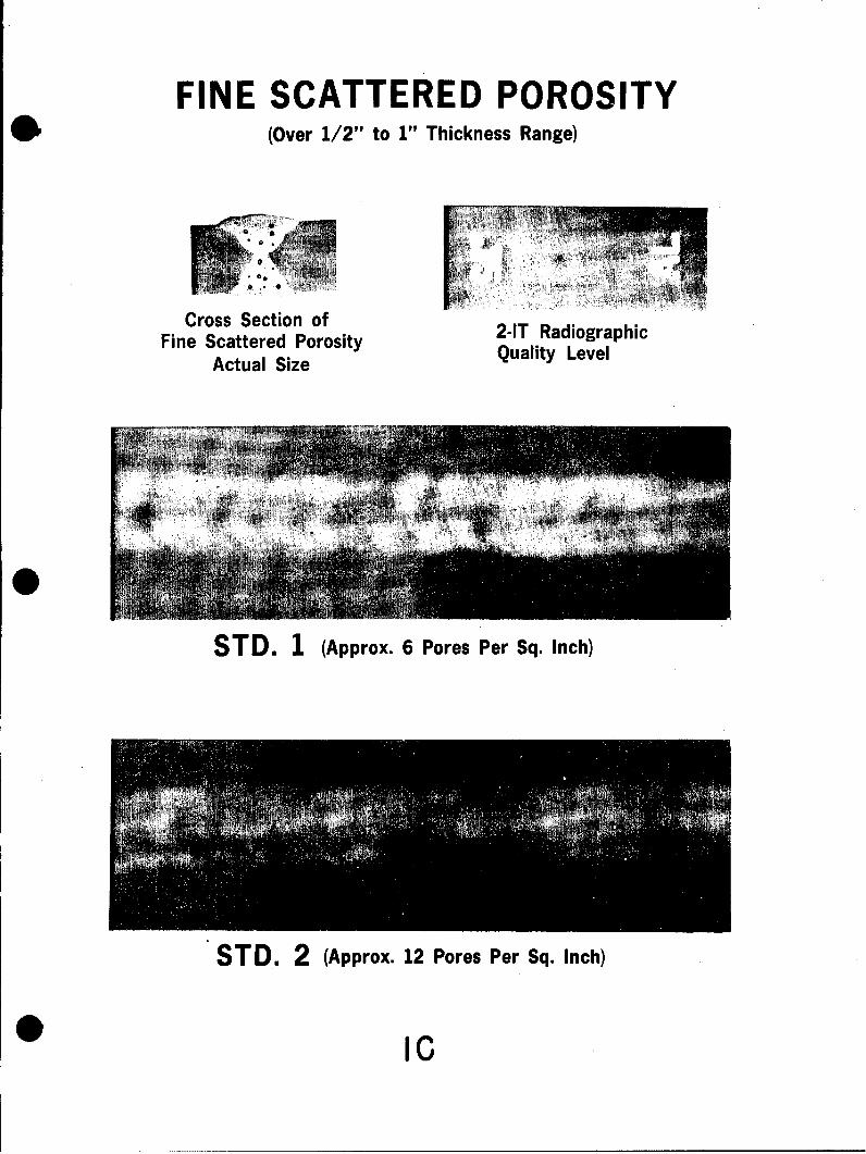
FINE SCATTERED POROSITY* (Over 1/2" to 1" Thickness Range)
~N
Cross Section of 2-IT RadiographicFine Scattered Porosity Quality Level
Actual Size
TD 1(po 6
STD. 1 (Approx. 6 Pores Per Sq. Inch)
STD. 2 (Approx. 12 Pores Per Sq. Inch)

FINE SCATTERED POROSITY(Over 1/2" to 1" Thickness Range)
STD. 3 (Approx. 25 Pores Per Sq Inch)
STD. 4 (Approx. 50 Pores Per Sq. Inch)
STD. 5 (Approx. 100 Pores Per Sq. Inch)
20 0

COARSE SCATTERED POROSITYS(Over 1/2" to 1" Thickness Range)
Cross Section of 2-IT RadiographicCoarse Scattered Porosity Quality Level
Actual Size
STD. 1 (Approx 2 Pores Per Sq. Inch)
STD. 2 (Approx. 4 Pores Per Sq. Inch)
30

COARSE SCATTERED POROSITY(Over 1/2" to 1" Thickness Range)
STD. 3 (Approx. 8 Pores Per Sq. Inch)
ToP
STD. 4 (Approx. 16 Pores Per Sq. Inch)
4C
40 ;•
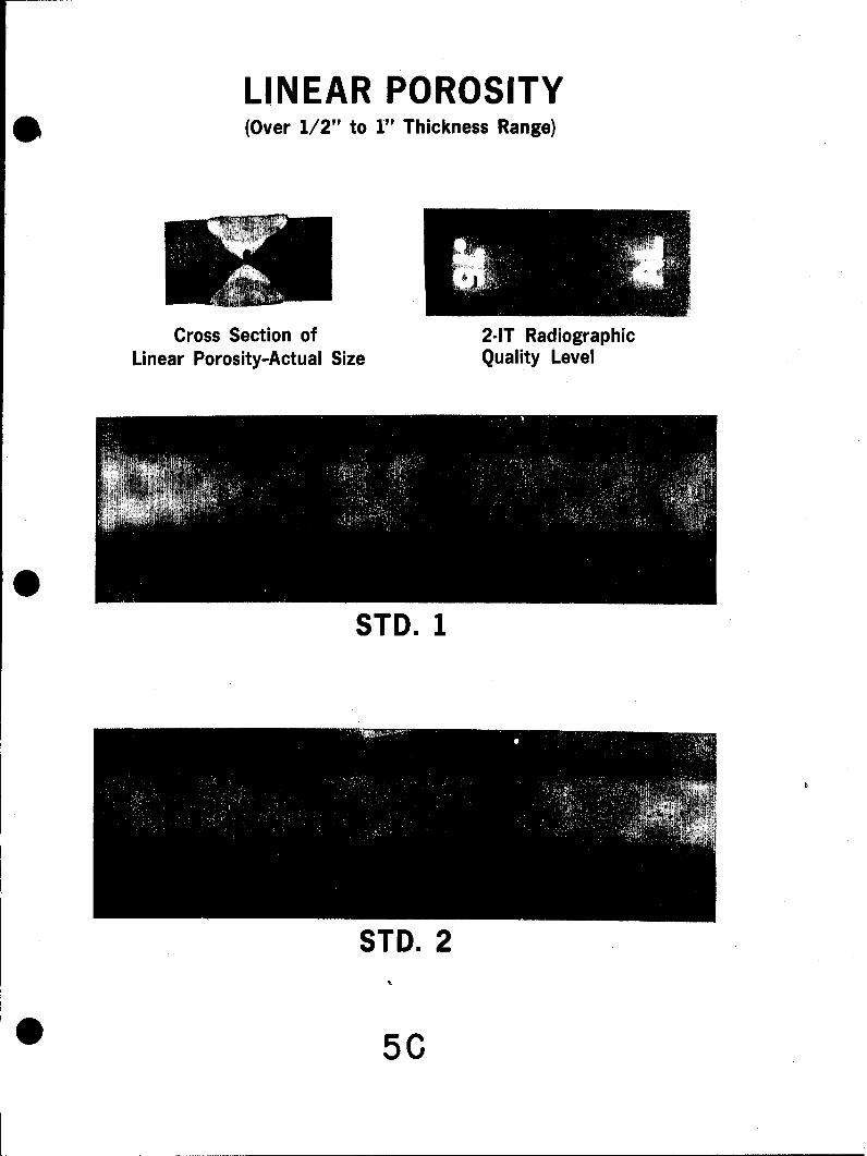
LINEAR POROSITY* (Over 1/2" to 1" Thickness Range)
Cross Section of 2-IT RadiographicLinear Porosity-Actual Size Quality Level
0STD. 1
STD. 2
"0 50

LINEAR POROSITY(Over 1/2 to 1" Thickness Range)
STD. 3
STD. 4
STD. 5
60

CLUSTERED POROSITY(Over 1/2" to 1" Thickness Range)
Cross Section of 2-IT RadiographicClustered Porosity-Actual Size Quality Level
STD. 1
STD. 2
SSTD. 3 NOTE: Any condition more
Ssevere
than Std. 3 shall
7C be judged as scattered porosity.

INCOMPLETE PENETRATION(Over 1/2 to 1" Thickness Range)
Cross Section of Cross Section ofPlate C-19-Actual Size Plate C-20-Actual Size
ABOVE - Faint image due to tight fit of plates.
BELOW - Heavy image due to plate separation.
ILLUSTRATIONS OF INCOMPLETE PENETRATION -Std. 1 - 1"
Reference standards are based on flaw length as Std. 2 - 2"follows: The accumulated length of flaw shall not Std. 3 - 4"exceed the limit stated for each standard in any Std. 4 - 7"10 inch weld length. Std. 5 - 10"
8C

* ISECTION D
REFERENCE RADIOGRAPHSFOR
FULL PENETRATIONALUMINUM WELDS
(MIG WELDING PROCESS)
THICKNESS RANGEI OVjER 1"1 TO 2"

0
CONTENTS
Reference Radiographs Page No.
Fine Scattered Porosity 1D- 2D
Coarse Scattered Porosity 3D -4D
Linear Porosity 5D - 6D
Clustered Porosity 7D
Incomplete Penetration 8D- 9D0
0

FINE SCATTERED POROSITY(Over 1" to 2" Thickness Range) S
2-IT Radiographic
Cross Section of Quality Level
Fine Scattered PorosityActual Size
SA
STD. 1 (Approx. 6 Pores Per Sq. Inch)
mw
STD. 2 (Approx. 12 Pores Per Sq. Inch
ID S

FINE SCATTERED POROSITY* (Over 1" to 2" Thickness Range)
STD. 3 (Approx. 25 Pores Per Sq. Inch)
..i? ....... ...
STD. 4 (Approx. 50 Pores Per Sq. Inch)
STD. 5 (Approx. 100 Pores Per Sq. Inch)
22D

COARSE SCATTERED POROSITY,(Over 1" to 2" Thickness Range)
2-IT RadiographicCross Section of Quality Level
Coarse Scattered PorosityActual Size
STD. 1 (Approx. 2 Pores Per Sq. Inch.)
STD. 2 (Approx. 4 Pores Per Sq. Inch)
3D

COARSE SCATTERED POROSITY*) (Over 1" to 2" Thickness Range)
STD. 3 (Approx 8 Pores Per Sq. Inch)
STD. 4 (Approx. 16 Pores Per Sq. Inch)
STD. 5 (Approx. 32 Pores Per Sq. Inch)
4D

LINEAR POROSITY(Over 1" to 2" Thickness Range) S
2-IT Radiographic
Cross Section of Quality Level
Linear Porosity-Actual Size
STD. 1
STD. 2
5D

LINEAR POROSITY* (Over 1" to 2" Thickness Range)
STD. 3
STD. 4
STD. 5
0 6D

CLUSTERED POROSITY* (Over 1" to 2" Thickness Range)
2-IT Radiographic
Cross Section of Clustered Porosity Quality Level
STD. 1
STD. 2
* STD. 3 NOTE: Any condition moresevere than Std. 3 shallbe judged as scattered porosity.',

INCOMPLETE PENETRATION(Over 1" to 2" Thickness Range)
2-IT Radiographic
Cross Section of Quality Level
Plate 19D-Actual Size
~
ABOVE - Faint image due to tight fit of plates.
BELOW - Heavy image due to plate separation.
ILLUSTRATIONS OF INCOMPLETE PENETRATION
8D

INCOMPLETE PENETRATION(Over 1" to 2" Thickness Range)
Cross Section of Cross Section ofPlate 20D-Actual Size Plate 21D-Actual Size
0
Incomplete Penetration and Lack of Fusion.
ILLUSTRATIONS OF INCOMPLETE PENETRATION - Std. 1 - V/2
Reference standards are based on flaw length as Std. 2 - 3"
follows: The accumulated length of flaw shall not Std. 3 - 6"
exceed the limit stated for each standard in any Std. 4 - 9"
12 inch weld length. Std. 5 - 12"
9D

*SECTION E
ILLUSTRATIONS OF
UNGRADED FLAWS
FOR FULL PENETRATION0
ALUMINUM WELDS
...... ...

CONTENTS
Ungraded Flaws Page No.
Longitudinal Cracks 1E
Transverse Cracks 2E
Plate Separation 2E
Oxide Inclusions 3E
Undercutting 4E
Incomplete Weld 4E
9

UNGRADED FLAWS
Cross Section of Cross Section ofPlate 1E-Actual Size Plate 2E--Actual Size
oVm
ILLUSTRATIONS OF LONGITUDINAL CRACKS(All Cracks are unacceptable)
IE
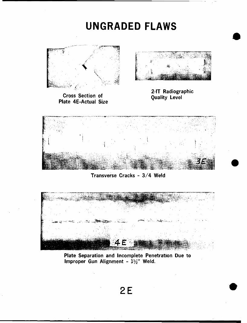
UNGRADED FLAWS
2-IT RadiographicCross Section of Quality Level
Plate 4E-Actual Size
Transverse Cracks - 3/4 Weld
Plate Separation and Incomplete Penetration Due toImproper Gun Alignment - 11" Weld.
2 E

UNGRADED FLAWS
Cross Section of 2-IT RadiographicPlate 5E-Actual Size Quality Level
0
ILLUSTRATIONS OF OXIDE INCLUSIONS
(Judge severity according to scattered Porosity)
3 E

UNGRADED FLAWS
Cross Section of Cross Section ofPlate 7E-Actual Size Plate 8E-Actual Size
Undercutting
V
Incomplete Weld
ILLUSTRATIONS OF UNDERCUTTING AND INCOMPLETE WELD(Both conditions are normally detected visually)
4E