uk atc 2015: cfd - a practical tool for large passenger carrying vehicles
TRANSCRIPT

CFD a practical tool for large passenger carrying vehicles
• Laurence Wood • Team leader test & development • Plaxton (Part of the ADL Group) • Engineer
– mechanical – Structural and Systems Analysis – Structural and Systems Testing

Background
• As a business we are increasingly challenged by product diversity and reduced time to market.
• Our CAE approach is based around improved problem understanding and iterative advancement.
• With respect to CAE simulation tools we tend to be Product rich and Resource Poor.
• But we are continually evolving.

We have evolved our CAE capabilities over the years
• Hand Calcs • Punched card analysis • 1D FEA analysis, implicit • 2D FEA analysis, implicit • 2D FEA Crash analysis, explicit • ~CFD~

The Opportunity
• As a rapidly growing business we face increasing technical challenges which CFD could potentially assist
• Cooling • HVAC • Aerodynamic & Fuel efficiency • Poor weather Visibility

The Project
• Evaluate the practicalities of CFD with respect to large passenger carrying vehicles
• Ease of model creation and interrogation • Required knowledge to get simple results • Required computing power to get simple
results • Method of validation, (Visual Engineering
Validation)

Target Vehicle (E400)

Project outline
• Static internal air flow • Static exterior pressure distribution • Transient internal thermal analysis
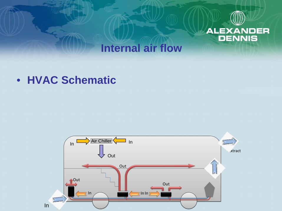
Internal air flow
• HVAC Schematic
OutOut
In InIn
Out
Extract
In
Out
In In Air Chiller

Level of Model Detail (Interior Air Flow)

Domain Inlets & Outlets
Heater Inlets into driver cabin: 14.3m/s
Inlet fan: 7.5 m/s
Inlets Top deck floor: 1.7 m/s
Inlet Chiller: 180 ft3/min
Inlet from Outside: 8.03m/s
Upper Deck Demisters: 5.3 m/s


External Air Flow

Level of Model Detail (Exterior Air Flow)

External Air Flow

External pressure distribution

Reversed Air Flow

External air flow what ifs Original Vehicle Geometry

External air flow what ifs HyperMesh Mesh Morphing

Morphed Mesh Geometry

CD = 0.494 ; CL = 0.019 Original Geometry

Iteration 1
CD = 0.461 ; CL = 0.020

Iteration 2
CD = 0.486 ; CL = 0.011

Iteration 4
CD = 0.452 ; CL = 0.007

Iteration 3
CD = 0.413 ; CL = 0.118

External Air Flow comparison results
Drag (N) Lift (N) CD CL L/DOriginal 1241 48.3 0.494 0.019 0.039Design1 1158 49.1 0.461 0.020 0.042Design2 1220 27.6 0.486 0.011 0.023Design4 1135 17.2 0.452 0.007 0.015Design3 1036 297.1 0.413 0.118 0.287

Transient Thermal Analysis
Heater Inlets into driver cabin: 14.3m/s, 30°C
Inlet fan: 7.5 m/s, 30°C
Inlets Top deck floor: 1.7 m/s, 30°C
Inlet Chiller: No Flow
Inlet from Outside: 8.03m/s, 30°C
Upper Deck Demisters: 5.3 m/s, 30°C

Temperature Results 566 second

Time Dependent Temperature Results

Summary of Resource
• Internal Air Flow: – 80% CAD manipulation, 20% Model build, 108 hours – Simulation Pre and Post Processing 32 hours
• External air Flow: – Lift converged within 120 time steps: 5.9 hours run
time on 128 cores • Thermal Transient:
– 300 sec simulation time required <7 hours on 64 cores

Internal CFD investigations Coach Racks

Outlet air velocities

Rack Air Flow, Stream Lines
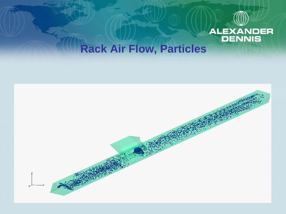
Rack Air Flow, Particles

Rack Plenum Pressure Profile

Summary of Evaluation
• Current HyperMesh skills a good start point • Acusolve CFD give good visualisation
results for a relatively simplistic modelling approach
• For broad-based CFD problem appreciation and understanding good engineering visualisation correlation was achieved
• Excellent starting point to evolve in-house CFD capabilities

CFD a practical tool for large passenger carrying vehicles
Thank You