ukccs winter school carbon dioxide transport ... · pdf filecarbon dioxide transport...
TRANSCRIPT

Carbon Dioxide Transport Infrastructure for the UK
Research Activitiesat the
Newcastle University
UKCCS Winter School
CO2 Transport in CCS
Martin Downie
School of Marine Technology, University of Newcastle

Introduction• Transport of CO2 until recently received relatively little
attention in the CCS debate because it was generally held to be a routine and proven technology, as evidenced by experience largely in the USA up to the present day.
• There are important differences between CO2 transport as it has been practised in the US for EOR, and how it needs to be practised in different countries in the future for mitigating climate change (with or without EOR).
• In addition, the CO2 transport requirements of other countries differ to varying degrees with regard to industry drivers, geographical and demographic characteristics and consequent technical and regulatory outcomes.
• CO2 transport outside the US raises new challenges and opportunities.
• The presentation focusses on some of the technical issues involved
9th February 2UKCCSC Winter School 2011

CO2 Transport Issues• CO2 transport until now has been concerned with purpose designed
‘natural’ (mostly) CO2 pipelines running exclusively overland through relatively sparsely populated regions.
• In the future, CCS for climate change mitigation will require aninfrastructure to transport anthropogenic ‘impure’ CO2 from multiple sources overland through often densely populated regions to storage sites, which may be subsea, using existing infrastructure where possible and desirable.
• The infrastructure may include other transport modes.• Countries adopting CCS will need to introduce a legal framework
for the design, operation and maintenance of dense phase CO2pipelines, and other transport modes, which will set technical constraints
• The properties of anthropogenic CO2 and its capture could have important implications for pipeline design procedures and practice, and for the legislation governing its implementation.
9th February 3UKCCSC Winter School 2011

Options: pipelines and ships• Economic large scale transport
in semi-pressurised vessels at pressures near the triple point (6.5 bar,-52oC)
• Process: Liquefaction, Storage, Loading, (Offshore) Unloading, Injection
• Requires harbour alterations and either offshore unloading or collection hub
• Competes with pipelines over large distances
• Flexibility allows collection from isolated sources and delivery to short life sinks
Offsho
rePipe
line Onshore
pipeline
Ship
9th February 4UKCCSC Winter School 2011

9th February UKCCSC Winter School 2011
Source: CO2Norway (2004)
Previous experience: Land Based Pipelines
5

9th February UKCCSC Winter School 2011
Existing Pipelines Transporting CO2
Pipeline LocationCO2
Capacity (Mt/y)
Length (km)
MAOP(bar)
Source Year
Cortez USA 19.3 808 186McElmo Dome
1984
Sheep Mountain USA 9.5 660 132Sheep Mountain
1983
Bravo USA 7.3 350 165 Bravo Dome 1984
Central Basin Pipeline
USA 20 278 170Denver City Hub
1985
NEJD USA -- 295 152Jackson Dome
1986
Bati Raman Turkey 1.1 90 170 Dodan Field 1983
6
Pipeline LocationCapacity
(Mt/y)Length (km)
MAOP (bar)
Source Year
Canyon Reef Carriers
USA 5.2 225 140 Gasification Plant 1972
Val Verde USA 2.5 130 140 Val Verde Gas Plant 1998
Bairoil USA 8.3 180 - La Barge Gas Plant 1986
WeyburnUSA & Canada
5 328186 & 204
Gas Plant 2000
Snohvit Norway 0.7 153 200 LNG Plant 2008
• Much more experience with pipelines transporting ‘natural’ CO2
• No CO2 transported from power plant
• Snohvit is the only sub-sea CO2pipeline

9th February UKCCSC Winter School 2011
Offshore Pipelines
• CO2 is separated during LNG production
• Transported back to Snøvhit field and injected into Tubåen Formation
• 8” pipeline constructed all subsea
• Projected to store 0.7Mt/year
• Only project operated by Statoil
7

9th February UKCCSC Winter School 2011
• CO2 is not explosive or inflammable like natural gas and is odourless• Can exist as solid, liquid, gas or dense phase• CO2 is denser than air and might accumulate in depressions or valleys• High concentrations of CO2 might have negative impacts on humans
(asphyxiation) & ecosystems• Above concentrations of 25-30%, CO2 is lethal. Need to set acceptable
levels for CO2 exposure • Best transported in liquid or dense phase• Dense phase: density of a liquid, viscosity of a gas• Properties are sensitive to impurities• CO2 mixtures do not corrode pipelines if ‘dry’ even in presence of co-
products such as NOx and Sox• Modelling the phase behaviour and hydraulics of CO2 mixtures is not
straightforward and requires empirical input and validation
Properties of CO2
8

9th February UKCCSC Winter School 2011
Properties of CO2
0
20
40
60
80
100
120
140
160
180
200
-100 -90 -80 -70 -60 -50 -40 -30 -20 -10 0 10 20 30 40 50 60
Temperature /degC
Pres
sure
/bar
Vapour CO2
Liquid CO2
Solid CO2
Supe
rcri
tical
CO
2
Critical point
Triple Point
Den
se P
hase
CO
2
Ships, trucks, trains
Pipelines
Pipelines
9

9th February UKCCSC Winter School 2011
CO2 mixturesTransported CO2
CO2 CH4 N2 H2S C2+ CO O2 Source
Canyon Reef Carriers
95% 5% <0.5% 100ppm -- -- -- Anthropogenic
Central Basin Pipeline
98.5% 0.2% 1.3% -- -- -- -- Natural
Sheep Mountain Source
96.8% 1.7% 0.9% -- 0.6% -- -- Natural
Bravo Dome Source
99.7% -- 0.3% -- -- -- -- Natural
Weyburn 96% 0.7% <300ppm 0.9% 2.3% 0.1% <50ppm Anthropogenic
10
Capture Technology ComponentCoal Fired% Volume
Gas Fired% Volume
Post Combustion CaptureSO2 <0.01 <0.01
NO <0.01 <0.01
N2/Ar/O2 0.01 0.01
Pre Combustion Capture (IGCC)
H2S 0.01-0.6 <0.01
H2 0.8-2.0 1
CO 0.03-0.4 0.04
CH4 0.01 2
N2/Ar/O2 0.03-0.6 1.3
OxyfuelSO2 0.5 <0.01
NO 0.01 <0.01
N2/Ar/O2 3.7 4.1
• Anthropogenic CO2 stream carries more co-products than ‘natural’ CO2stream
• CO2 captured from power plants contains co-products not previously transported

9th February UKCCSC Winter School 2011
Phase Diagram for CO2 mixtures
30
40
50
60
70
80
0 5 10 15 20 25 30 35
Temperature /degC
Pres
sure
/bar
Post Combustion - Gas and Coal
Pre Combustion - Coal
Pre Combustion - Gas
Pure Carbon Dioxide
11

9th February UKCCSC Winter School 2011
Phase Diagram for CO2 mixtures
12
30
40
50
60
70
80
90
100
0 5 10 15 20 25 30 35 40Temperature / degC
IPCC Coal
ENCAP Coal CO2/H2S
ENCAP Coal CO2+H2S
O&R Coal & Gas
IPCC Gas
Pure CO2
Pre
ssu
re (
bar
)
Oxyfuel Specifications

Pipeline calculations
• At its simplest, flow in a pipe occurs when the pressure forces are sufficient to overcome the resistance forces provided by friction and gravity. Analysis along these lines leads to the flow equation.
• Frictional forces can be predicted from empirical regression equations.
• There is a pressure drop along the length of the pipe.
9th February 13UKCCSC Winter School 2011
dF4 = πD dy τ
• Objectives of pipeline design include delivering the desired flow rate at acceptable pressures, and velocities that are low enoughto avoid damaging the pipe and high enough for viable pigging.

9th February UKCCSC Winter School 2011
Pipeline flow equations are derived from the equation for one dimensional fluid flow in a horizontal pipe (as cited by Schroeder (2001) and modified to account for changes in elevation):
Flow equations
14
5.0225.2
−−=dwaa
coi
b
b
fZLGT
hPPeD
P
TCQ
where: C is a constant, D is the pipe diameter (in mm), e is the pipe efficiency, fdw ,is the Darcy-Weisbach friction factor, G is the Gas specific gravity, L is the Pipe length (km), Pb is the Pressure base (kPa), Pi is the Inlet pressure (kPa), Po is the Outlet pressure kPa), Q is the Flow rate (m3/day), Ta is the Average temperature (°K), Tb is the Temperature base (°K) and Za is the Compressibility factor.

9th February UKCCSC Winter School 2011
• Parameters in the flow equation are governed by the phase behaviour of the fluid which can be modelled by equations of state (EoS).
• Equations of state are empirical relationships based on the ideal gas laws modified to conform to experimental data.
• The flow equation together with the EoS have to be successively modified to account for two phase flow, the presence of co-products, the ability to model transients.
• The solution of the equations becomes increasingly complex.
• Simplified equations exist for initial pipe sizing exercises.
Flow equations and Equations of State
15
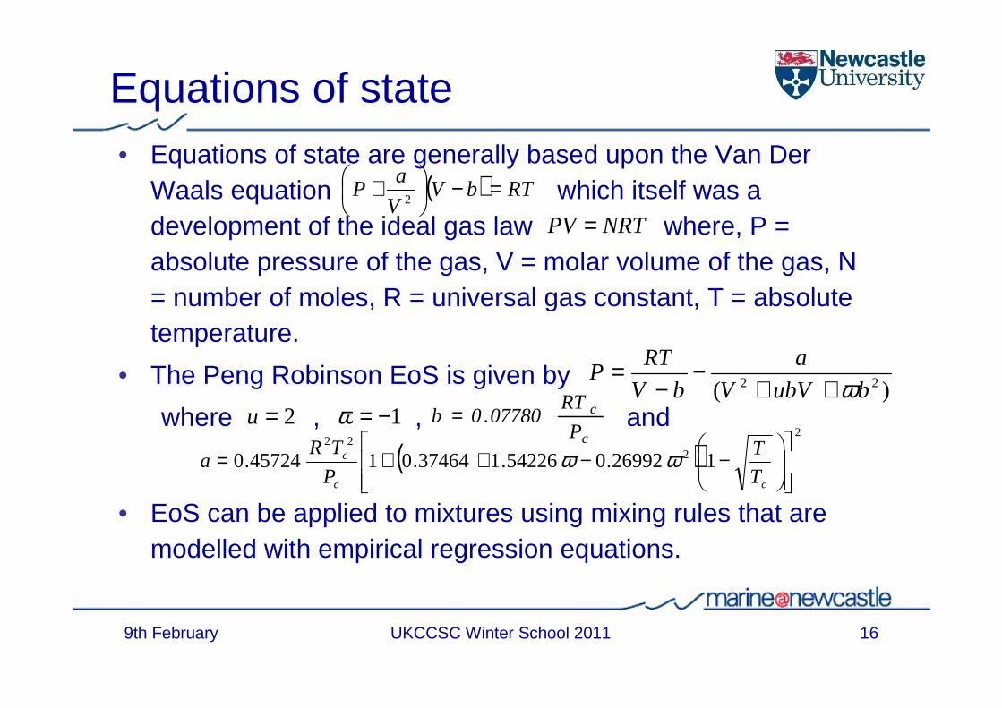
Equations of state• Equations of state are generally based upon the Van Der
Waals equation which itself was a development of the ideal gas law where, P = absolute pressure of the gas, V = molar volume of the gas, N = number of moles, R = universal gas constant, T = absolute temperature.
• The Peng Robinson EoS is given by
where , , and
• EoS can be applied to mixtures using mixing rules that are modelled with empirical regression equations.
9th February 16UKCCSC Winter School 2011
NRTPV =( ) RTbV
V
aP =−
+2
)( 22 bubVV
a
bV
RTP
ω++−
−=
2=u 1−=ω
( )2
222
126992.054226.137464.0145724.0
−−++=
cc
c
T
T
P
TRa ωω
c
c
P
RT07780.0b =
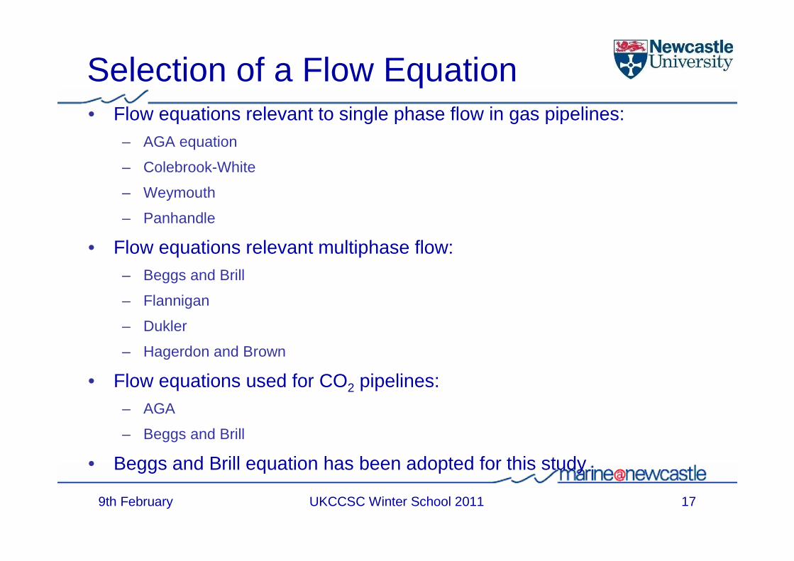
Selection of a Flow Equation• Flow equations relevant to single phase flow in gas pipelines:
– AGA equation
– Colebrook-White
– Weymouth
– Panhandle
• Flow equations relevant multiphase flow:– Beggs and Brill
– Flannigan
– Dukler
– Hagerdon and Brown
• Flow equations used for CO2 pipelines:– AGA
– Beggs and Brill
• Beggs and Brill equation has been adopted for this study
9th February 17UKCCSC Winter School 2011

Selection of an Equation of State
• Available EOSs include:– Peng-Robinson (PR)– Modified Peng-Robinson– Soave-Redlich-Kwong (SRK)– Modified Soave-Redlich-Kwong– Benedict-Webb-Rubin-Starling (BWRS)– European Gas Research Group (GERG)– Li-Kessler – Span and Wagner
• Currently no validated EOS for CO2 containing impurities in the dense phase
• Peng Robinson selected for the study but ongoing research being conducted in this area
9th February 18UKCCSC Winter School 2011

9th February UKCCSC Winter School 2011
Simple models
• There are occasions when simplified equations are used, eg a number of simple cost models (MIT, Ecofys, IEA GHG) use a simplified flow equation for pipe sizing, eg
• The wall thickness, t, is obtained from the design pressure which allows the weight of the pipeline to be estimated
where F, L, J and T are Design, Location Joint and Temperature Correction factors fixed by Regulatory Codes
• The velocity, us, must be smaller than the erosional velocity, ue,
• (see Mohitpour et al. (2007) for further details)
19
=f
( )tDtLW os += ρπ
2PD
Q
T
Tcu b
b
fus =
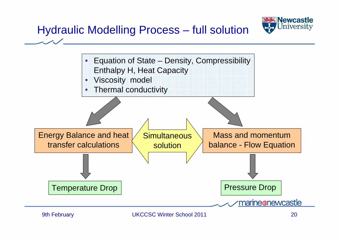
Hydraulic Modelling Process – full solution
• Equation of State – Density, Compressibility Enthalpy H, Heat Capacity
• Viscosity model• Thermal conductivity
Mass and momentum balance - Flow Equation
Pressure Drop
Energy Balance and heat transfer calculations
Temperature Drop
Simultaneous solution
9th February 20UKCCSC Winter School 2011

9th February UKCCSC Winter School 2011
Variation in Density for CO2 mixtures
0
100
200
300
400
500
600
700
800
900
1000
0 10 20 30 40 50 60 70 80 90 100 110 120 130 140 150 160 170 180 190
Pressure /bar
Den
sity
/kg/
m^3
Pure Carbon Dioxide5% Argon5% Carbon Monoxide5% Hydrogen5% Hydrogen Sulphide5% Methane5% Nitrogen5% Nitrogen Dioxide5% Oxygen5% Sulphur Dioxide
Calculations conducted at 20°C
21
9th February UKCCSC Winter School 2011
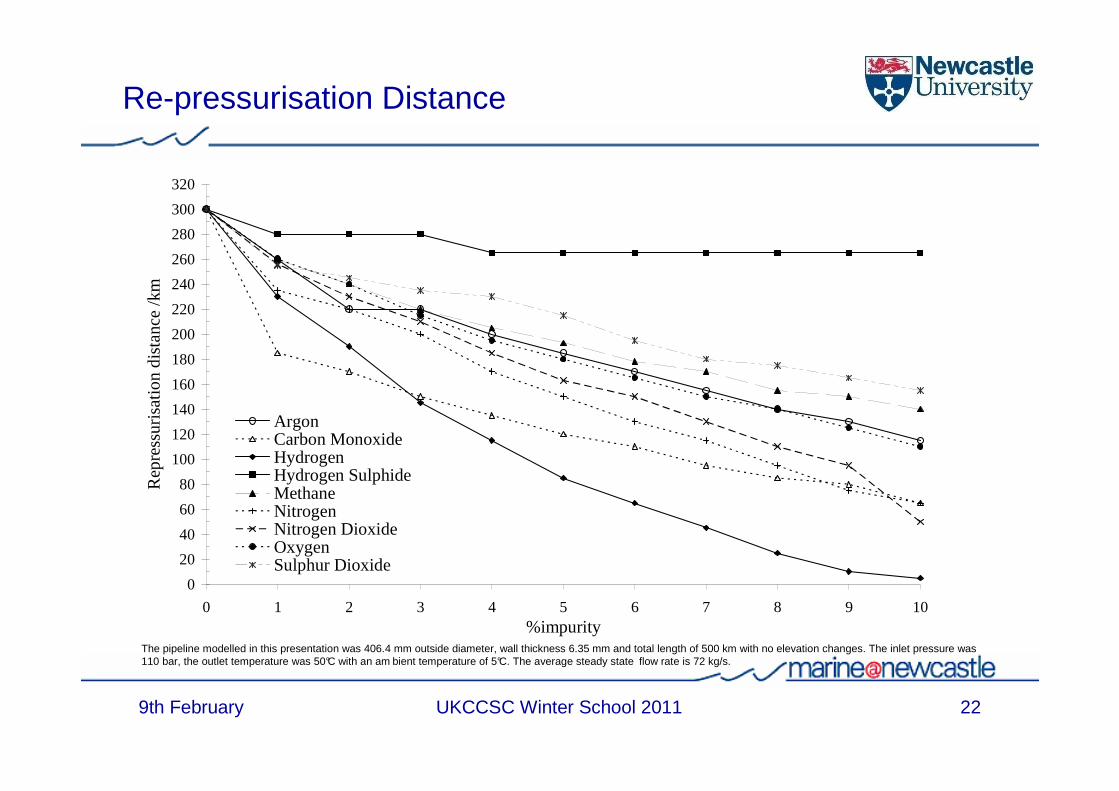
Re-pressurisation Distance
The pipeline modelled in this presentation was 406.4 mm outside diameter, wall thickness 6.35 mm and total length of 500 km with no elevation changes. The inlet pressure was 110 bar, the outlet temperature was 50°C with an am bient temperature of 5°C. The average steady state flow rate is 72 kg/s.
0
20
40
60
80
100
120
140
160
180
200
220
240
260
280
300
320
0 1 2 3 4 5 6 7 8 9 10%impurity
Rep
ress
uris
atio
n di
stan
ce /k
m
ArgonCarbon MonoxideHydrogenHydrogen SulphideMethaneNitrogenNitrogen DioxideOxygenSulphur Dioxide
22

9th February UKCCSC Winter School 2011
Fluid properties of CO2 streams
23
0
10
20
30
40
50
60
70
80
90
0 5 10 15 20 25 30 35
Temperature /degC
Pre
ssu
re /b
ar
Best Case: IPCC Post Combustion
Worst Case: O&R Oxyfuel
Pure Carbon Dioxide
0
100
200
300
400
500
600
700
800
900
1000
25 50 75 100 125 150
Pressure /bar
Den
sity
/kg
.m-3
Best case at 5 degCBest case at 10 degCBest case at 20 degCWorst case 5 degCWorst case 10 degCWorst case 20 degCPure carbon dioxide at 5 degCPure carbon dioxide at 10 degCPure carbon dioxide at 20 degC
0.00
0.02
0.04
0.06
0.08
0.10
0.12
25 50 75 100 125 150
Pressure /bar
Vis
cosi
ty /c
P
Best case at 5 degCBest case at 10 degCBest case at 20 degCWorst case 5 degCWorst case 10 degCWorst case 20 degCPure carbon dioxide at 5 degCPure carbon dioxide at 10 degCPure carbon dioxide at 20 degC
0.00
0.10
0.20
0.30
0.40
0.50
0.60
0.70
0.80
0.90
1.00
0 10 20 30 40 50 60 70 80 90 100 110 120 130 140 150 160
Pressure /bar
Co
mp
ress
ibili
ty
Best case at 5 degCBest case at 10 degCBest case at 20 degCWorst case 5 degCWorst case 10 degCWorst case 20 degCPure carbon dioxide at 5 degCPure carbon dioxide at 10 degCPure carbon dioxide at 20 degC

9th February UKCCSC Winter School 2011
Capture Technology and Re-pressurisation Distance
0
0.2
0.4
0.6
0.8
1
1.2
1.4
0 0.1 0.2 0.3 0.4 0.5 0.6 0.7 0.8 0.9 1
Distance along Pipeline/Pipeline Length
Pre
ssur
e/(C
ritic
al P
ress
ure+
10ba
r)
Post Combustion - Coal & Gas (IPCC)
Pre Combustion - Coal (IPCC)
Pre Combustion - Gas (IPCC)
Oxyfuel - Coal (IPCC)
Oxyfuel - Gas (IPCC)
Pure Carbon Dioxide
24

9th February UKCCSC Winter School 2011
Issues: Corrosion Prevention
Drying the product stream• Carbon dioxide corrosion will not occur if free water is not
present• The water specification is dependent on the solubility of water
in the fluid at the operating temperature and pressure• Solubility limit for water in pure CO2 at pipeline operating
conditions is up to 1.69 g/m3
• Corrosion of carbon steel will not occur if the water content isbelow 60% saturation (1.02 g/m3)
• Industry accepted levels of water for pipeline facilities are conservatively specified between 0.288-0.480 g/m3
• Dehydration is expensive!
25

9th February UKCCSC Winter School 2011
Issues: Corrosion Prevention Options
• Drying the product stream
– Effect of impurities– Solubility of water in CO2
in liquid and supercritical phase decreases with increasing CH4 content
– No data available for mixtures of CO2/N2 and CO2/H2S
• Use an inhibitor
Source: Heggum et al (2005)
26

9th February UKCCSC Winter School 2011
Issues: Propagating Fractures
Propagating brittle fracture• Risk of long running brittle fracture due to
cooling effects around leaksPropagating ductile fracture• In-service ductile fractures have
propagated up to 300m in natural gas pipelines
• Need to understand the nature the decompression process & fracture velocity
• Decompression dependent on gas composition
Fractures in natural gas pipelines
27

9th February UKCCSC Winter School 2011
Issues: Fracture of CO2 Pipelines
Cosham, A. & Eiber, R., “Fracture Control in CO2 Pipelines”, Presented at Transmission of CO2, H2 and biogas: exploring new uses for natural gas pipelines, Amsterdam, May 2007
Saturation Pressure
Arrest Pressure
28

9th February UKCCSC Winter School 2011
Issues: Ductile Fracture Arrest in CO2 Pipelines
CRC Pipeline Ductile Fracture Analysis (16”OD, 0.375”wt, X60 pipe)
29

9th February
Issues:Fracture Control
• Control of toughness– Specification of toughness to
prevent brittle fracture and to control ductile fracture
• Crack Arrestors– Use of mechanical devices along
the pipeline to arrest a propagating fracture
– CRC Pipeline in West Texas installed 100 ClockSprings at 2 mile intervals
– CBPL in West Texas installed crack arrestors every 0.25 mile and 300 feet at crossings
UKCCSC Winter School 2011 30
9th February UKCCSC Winter School 2011
Issues: CO2 Pipeline Risk Analysis - Consequences
• Need to know concentration of CO2 in area after leak • Dependent on:
– Pipeline size– Type of failure – Pressure at the point of failure– Phase changes as CO2 escapes from pipeline– CO2 composition– Block valve spacing (inventory of CO2 available)– Topography in region of leak– Weather conditions
31

9th February
Issues: Risk Assessment for CO2 Pipelines
• Determine risk contours for distances from the pipeline leak & therefore the safe distances
• Defines zones in which the pipeline should avoid residential areas
• Requires definition of acceptable risk levels and exposure limits
Source: Turner R., Hardy, N. and Hooper, B. (2006), ‘Quantifying the risks associated with a CO2 pipeline: A methodology case study, GHGT8, Trondheim, Norway, 19th-22nd June 2006
UKCCSC Winter School 2011 32

9th February UKCCSC Winter School 2011
Issues: Regulation and Design Standards
Pipeline Regulations and Codes
United Kingdom United States
Health and Safety Executive Department of Transport Pipeline and Hazardous Materials Safety Administration (PHMSA) - Office of Pipeline Safety (OPS)
Pipeline Safety Regulation (PSR) Code of Federal Regulation – 49CFR192 and 49CFR195
Design Codes & Recommended Practice
Design Codes
PD 8010 - Onshore and Offshore Liquid
and Gas
IGE /TD/1-Onshore Gas 1 to 100 bars
ASME B31.4 (Liquid)
ASME B31.8 (Gas)
Regulator
Legislation
Codes & Standards
33

9th February
• In US, classified under 49 CFR Part 195 – “Transportation of Hazardous Liquids by Pipeline”
• Applicable design code - ASME B31.4 “Liquid Transportation System for Hydrocarbons, Liquid Petroleum Gas and Anhydrous Ammonia and Alcohols” makes specific mention to CO2
• Most operators have designed CO2 pipelines to ASME B31.8“Gas Transmission and Distribution Piping Systems”
• PSR 1996 has no substance classification of CO2 – is being updated for CCS applications
• Applicable design code - UK PD BS 8010• CO2 is a classified as Category C substance “non-flammable
liquids that are non toxic gases at ambient temperature and atmospheric pressure”
• Supercritical CO2 is not classified
Issues: Regulation - Codes & Standards for CO2
34UKCCSC Winter School 2011

9th February UKCCSC Winter School 2011
Distribution of Sources and Cumulative Emissions
Source: BGS Database http://www.bgs.ac.uk/co2/ukco2.html
35

9th February UKCCSC Winter School 2011
Useful ReferencesAnheden, M., Andersson, A., Bernstone, C., Eriksson, S., Yan, Liljemark, S. & Wall, C.
“CO2 Quality Requirement for a System with CO2 Capture, Transport and Storage.” Proceedings of the 7th Greenhouse Gas Technologies Conference GHGT-7, Vancouver, Vol 2 pp. 2559-2563, 2005
Aspelund, A., Sandvik, T.E., Krogstad, H. and De Koeijer, G. (2004)“Liquefaction of Captured CO2 for Ship-Based Transport”, Proceedings of GHGT-7, Sept. 2004
Carroll,J. J.,“Compression and High Pressure Pipeline Transportation of Carbon Dioxide Rich Fluids,” 1st Regional Symposium on Carbon Management – Carbon Management Challenges and Opportunities for Petroleum Industry, May 22-24, 2006
Beggs, H.D. & Brill, J.P. (1973)“A Study of Two Phase Flow in Inclined Pipes,” Journal of Petroleum Technology, Vol. 25 (May), pp 607-617.
BGS (2004), GIS file provided courtesy of the British Geological Survey , UK., document website: http://www.bgs.ac.uk/co2/ukco2.html
CO2Norway (2004)“CO2 in the United States” Last updated 03.06.04. Available from: http://www.co2.no/default.asp?UID=54&CID=24.
Cosham, A. & Eiber, R. (2007)“Fracture Control in CO2 Pipelines”, Presented at Transmission of CO2, H2 and biogas: exploring new uses for natural gas
pipelines, Amsterdam, May 2007Farris, C.B., (1983) “Unusual Design Factors for Supercritical CO2 Pipelines”, Energy Progress, Vol.3, No. 3.Gale, J., & Davison, J., (2004)
“Transmission of CO2-safety and economic considerations” Energy, 29(9-10): 1319.Heggum, G., T. Weydahl, R. Mo, M. Mølnvik and A. Austergaard (2005)
CO2 Conditioning and Transportation Carbon Dioxide Capture for Storage in Deep Geologic Formations. D. C. Thomas and S. M. Benson, Elsevier Ltd. 2: 925-936
Hendriks, C., Hagedoorn, S. & Warmenhoven, H.,“Transportation of Carbon Dioxide and Organisational Issues of CCS in the Netherlands”, Report prepared by Ecofys for EnergieNed, the Ministry of Economic Affairs and the Ministry of Housing, Spatial Planning and the Environment, March 2007.
IEAGHG, “Impact of Impurities on CO2 Capture, Transport and Storage,” Report no. PH4/32, Study conducted by SNC Lavalin, August 2004.
36

ReferencesIEA (2005)
Building the Cost Curves for CO2 Storage, IEA Greenhouse Gas R & D Programme , Reports Nos 2005/2&3IPCC (2005)
IPCC special report on carbon dioxide capture and storage. Prepared by Working Group III of the Intergovernmental Panel on Climate Change, Edited by Metz, B., Davidson, O., de Coninck, H.C., Loos, M. and Meyer, L. A., Cambridge University Press, Cambridge, United Kingdom and New York, NY, USA, 442 pp
McCollum, S. And Rubin, E. (2007) “An Engineering Economic Model of Pipeline Transport of CO2 with Application to CCS”, Dept. Eng. And Public Policy, Carnegie Mellon University, Pittsburgh
Mohitpour, M., Golshan,H. And Murray, A. “Pipeline Design and Construction: A Practical Approach”, ASME PRESS, ISBN 0-7918-0257-4, 2007
McCollough, D.E..,“The Central Basin Pipeline: a CO2 System in West Texas” Energy Progress, 6(4), pp. 230-234, 1986Odenberger, M. and Svensson, R. (2003)
“Transportation system for CO2 – Applications to carbon sequestration”, Chalmers University of Technology, Goteburg, Sweden
Oosterkamp, A. and Ramsen, J., 2008, State-of-the-Art overview of CO2 pipeline transport with relevance to offshore pipelines, Polytec Report No. POL-O-2007-138-A, 8 January 2008
OPS (2000)Pipeline Safety: The Office of Pipeline Safety is changing how it oversees the pipeline industry, United States General Accounting Office GAO/RCED-00-128, 2000.
Trench, C. J. The U.S. Oil Pipeline Industry's Safety Performance, Allegro Energy Consulting, 2003.Visser, E. & Hendriks, C.“Towards Hydrogen and Electricity Production with Carbon Capture and Storage- DYNAMIS
Quality Recommendation,” DYNAMIS ,Project No.: 019672 , 2007White,V., Allam, R.& Miller, E.,“Purification of Oxyfuel Derived CO2 for Sequestration or EOR”, Proceedings of the 8th
Greenhouse Gas Technologies Conference GHGT-8, Trondheim, Norway, 2006Wong, S. (2005)
“Module 4 – CO2 Compression & Transportation to Storage Reservoir” in Building Capacity for CO2 Capture and Storage Project in the APEC Region: A Training Manual for Policy Makers and Practitioners APEC Reference #205-RE-01.3 Available from: http://www.delphi.ca/apec/
9th February 37UKCCSC Winter School 2011