ultra 100 series drives installation manual · ultra 100 series drives (cat. no. 1398-5.2)...
TRANSCRIPT
Installation Manual
ULTRA 100 SeriesDrives(Cat. No. 1398-5.2)
Allen-Bradley
Important User Information
Because of the variety of uses for the products described in this publication, those responsible for the application and use of this control equipment must satisfy themselves that all necessary steps have been taken to assure that each application and use meets all performance and safety requirements, including any applicable laws, regulations, codes and standards.
The illustrations, charts, sample programs and layout examples shown in this guide are intended solely for purposes of example. Since there are many variables and requirements associated with any particular installation, Allen-Bradley does not assume responsibility or liability (to include intellectual property liability) for actual use based upon the examples shown in this publication.
Allen-Bradley publication SGI-1.1, Safety Guidelines for the Application, Installation, and Maintenance of Solid-State Control (available from your local Allen-Bradley office), describes some important differences between solid-state equipment and electromechanical devices that should be taken into consideration when applying products such as those described in this publication.
Reproduction of the contents of this copyrighted publication, in whole or in part, without written permission of Allen-Bradley Company, Inc., is prohibited.
Throughout this manual we use notes to make you aware of safety considerations. For example:
Attention statements help you to:
identify a hazard
avoid the hazard
recognize the consequences
Mathcad is a registered trademark of MathSoft, Inc.Microsoft, MS-DOS and Windows are trademarks of Microsoft Corporation. UL and cUL are registered trademarks of Underwriters Laboratories.
!
Intro
ATTENTION: This symbol identifies information about practices or circumstances that can lead to personal injury or death, property damage or economic loss.
Note: This symbol identifies information that is critical for successful application and understanding of the product.
Table of Contents
IntroTable of Contents
Table of Contents Intro-3
List of Figures Intro-9
List of Tables Intro-13
Preface Intro-17
Who Should Use this Manual . . . . . . . . . . . . . . . . . . .Intro-17
ULTRA 100 Series Product Receiving and Storage Responsibility. .Intro-17
Rockwell Automation Support . . . . . . . . . . . . . . . . . . .Intro-18
Local Product Support. . . . . . . . . . . . . . . . . . . . . . . .Intro-19
Technical Product Assistance . . . . . . . . . . . . . . . . . . .Intro-19
Purpose and Contents of this Manual . . . . . . . . . . . . . . .Intro-19
Additional Instructions and Manuals . . . . . . . . . . . . . . .Intro-22
Host Commands and ULTRA Master . . . . . . . . . . . . .Intro-22
TouchPad . . . . . . . . . . . . . . . . . . . . . . . . . . . . .Intro-22
Symbols and Conventions . . . . . . . . . . . . . . . . . . . . .Intro-23
Typographical and Wording Conventions . . . . . . . . . . .Intro-23
Graphical Symbols . . . . . . . . . . . . . . . . . . . . . . . .Intro-24
Pictorial Index . . . . . . . . . . . . . . . . . . . . . . . . . . . .Intro-25
Chapter 1 SafetyInstalling and Using the ULTRA 100 Series Drive . . . . . . . . . 1-1
Potential Hazards . . . . . . . . . . . . . . . . . . . . . . . . . . . 1-1
Voltage Potentials . . . . . . . . . . . . . . . . . . . . . . . . . . 1-2
Your Responsibilities . . . . . . . . . . . . . . . . . . . . . . . . . . 1-2
General Safety Guidelines . . . . . . . . . . . . . . . . . . . . . . . 1-3
Chapter 2 Unpacking, Inspecting and StoringUnpacking the Drive. . . . . . . . . . . . . . . . . . . . . . . . . . . 2-1
Inspection Procedure . . . . . . . . . . . . . . . . . . . . . . . . . . 2-1
Testing the Unit . . . . . . . . . . . . . . . . . . . . . . . . . . . . . 2-2
Hardware Set Up . . . . . . . . . . . . . . . . . . . . . . . . . . . 2-2
Drive Checkout Test . . . . . . . . . . . . . . . . . . . . . . . . . 2-3
Storing the Unit . . . . . . . . . . . . . . . . . . . . . . . . . . . . 2-8
Chapter 3 Selecting Other System ComponentsULTRA 100 Series Overview . . . . . . . . . . . . . . . . . . . . . 3-1
Publication 1398-5.2 – PDF 1997
Intro-4 Table of Contents
ULTRA 100 Series Features . . . . . . . . . . . . . . . . . . . . . . 3-1
Drive Power Ratings . . . . . . . . . . . . . . . . . . . . . . . . . 3-1
High Performance Microcontroller Technology . . . . . . . . . . 3-2
IPM Technology. . . . . . . . . . . . . . . . . . . . . . . . . . . . 3-2
Analog and Digital Interfaces . . . . . . . . . . . . . . . . . . . . 3-2
Encoder Control . . . . . . . . . . . . . . . . . . . . . . . . . . . . 3-2
Encoder Output . . . . . . . . . . . . . . . . . . . . . . . . . . . . 3-2
Digital I/O . . . . . . . . . . . . . . . . . . . . . . . . . . . . . . . 3-2
Analog I/O . . . . . . . . . . . . . . . . . . . . . . . . . . . . . . . 3-3
AC Input Power . . . . . . . . . . . . . . . . . . . . . . . . . . . . 3-3
Personality Module . . . . . . . . . . . . . . . . . . . . . . . . . . 3-3
Multiple Protection Circuits . . . . . . . . . . . . . . . . . . . . . 3-3
Command Sources . . . . . . . . . . . . . . . . . . . . . . . . . . . . 3-3
Serial Command Sources . . . . . . . . . . . . . . . . . . . . . . . 3-3
Analog Command Sources . . . . . . . . . . . . . . . . . . . . . . 3-4
I/O Interface . . . . . . . . . . . . . . . . . . . . . . . . . . . . . . . . 3-4
Analog Input . . . . . . . . . . . . . . . . . . . . . . . . . . . . . . 3-4
Analog Output . . . . . . . . . . . . . . . . . . . . . . . . . . . . . 3-5
Digital Inputs . . . . . . . . . . . . . . . . . . . . . . . . . . . . . 3-5
Digital Outputs. . . . . . . . . . . . . . . . . . . . . . . . . . . . . 3-5
Auxiliary Encoder Interface . . . . . . . . . . . . . . . . . . . . . 3-6
ULTRA Master Software . . . . . . . . . . . . . . . . . . . . . . . . 3-6
Autotuning . . . . . . . . . . . . . . . . . . . . . . . . . . . . . . . 3-7
Agency Approvals . . . . . . . . . . . . . . . . . . . . . . . . . . . . 3-7
Interface Cables . . . . . . . . . . . . . . . . . . . . . . . . . . . . . . 3-7
Motors . . . . . . . . . . . . . . . . . . . . . . . . . . . . . . . . . . . 3-7
Options . . . . . . . . . . . . . . . . . . . . . . . . . . . . . . . . . 3-8
European Union Requirements . . . . . . . . . . . . . . . . . . . 3-9
Chapter 4 ULTRA Master InstallationHardware and Software Requirements . . . . . . . . . . . . . . . . . 4-1
Installing ULTRA Master . . . . . . . . . . . . . . . . . . . . . . . . 4-1
Starting and Quitting ULTRA Master . . . . . . . . . . . . . . . . . 4-2
From the C:> Prompt . . . . . . . . . . . . . . . . . . . . . . . . . 4-2
From Windows . . . . . . . . . . . . . . . . . . . . . . . . . . . . 4-3
The ULTRA Master Start-Up Screen . . . . . . . . . . . . . . . . 4-4
Version Level . . . . . . . . . . . . . . . . . . . . . . . . . . . . . . . 4-4
Miscellaneous Files. . . . . . . . . . . . . . . . . . . . . . . . . . . . 4-5
The readme File . . . . . . . . . . . . . . . . . . . . . . . . . . . . 4-5
Firmware Files . . . . . . . . . . . . . . . . . . . . . . . . . . . . . 4-5
Chapter 5 InstallationMechanical Installation Requirements . . . . . . . . . . . . . . . . . 5-1
Interface Connections . . . . . . . . . . . . . . . . . . . . . . . . . . 5-5
Publication 1398-5.2 – PDF 1997
Table of Contents Intro-5
Wiring . . . . . . . . . . . . . . . . . . . . . . . . . . . . . . . . . 5-5
Electromagnetic Compatibility . . . . . . . . . . . . . . . . . . . 5-7
AC Line Filters . . . . . . . . . . . . . . . . . . . . . . . . . . . . . 5-8
Chapter 6 InterfacesJ1 – Controller. . . . . . . . . . . . . . . . . . . . . . . . . . . . . . 6-1
Digital I/O Power. . . . . . . . . . . . . . . . . . . . . . . . . . . 6-1
Digital Inputs . . . . . . . . . . . . . . . . . . . . . . . . . . . . . 6-3
Input Interface Circuit Examples . . . . . . . . . . . . . . . 6-5
Auxiliary Encoder Input Types . . . . . . . . . . . . . . . . . . 6-20
Interface Cable Examples. . . . . . . . . . . . . . . . . . . . . 6-21
J1 Terminal Strip/Breakout Board. . . . . . . . . . . . . . . . 6-24
J2 – Encoder. . . . . . . . . . . . . . . . . . . . . . . . . . . . . . 6-29
J5 – Serial Port. . . . . . . . . . . . . . . . . . . . . . . . . . . . . 6-31
Serial Communications Overview. . . . . . . . . . . . . . . . 6-33
Four Wire RS-485 Connections. . . . . . . . . . . . . . . . . . 6-35
Interface Connections. . . . . . . . . . . . . . . . . . . . . . . . . 6-39
Chapter 7 Power Connections Motor Power Cabling. . . . . . . . . . . . . . . . . . . . . . . . . . 7-2
Shield Termination of Power Cables . . . . . . . . . . . . . . . 7-2
Motor Overload Protection. . . . . . . . . . . . . . . . . . . . . 7-4
Power Supply Protection. . . . . . . . . . . . . . . . . . . . . . . 7-5
Emergency Stop Wiring. . . . . . . . . . . . . . . . . . . . . . . 7-5
AC Power Cabling. . . . . . . . . . . . . . . . . . . . . . . . . . . . 7-7
DC Bus . . . . . . . . . . . . . . . . . . . . . . . . . . . . . . . . . . 7-9
Chapter 8 Application and Configuration ExamplesAnalog Control. . . . . . . . . . . . . . . . . . . . . . . . . . . . . . 8-1
Hardware Set Up. . . . . . . . . . . . . . . . . . . . . . . . . . . 8-1
Connection Diagram . . . . . . . . . . . . . . . . . . . . . . . . . 8-2
Configuration. . . . . . . . . . . . . . . . . . . . . . . . . . . . . 8-2
Tuning . . . . . . . . . . . . . . . . . . . . . . . . . . . . . . . . . 8-4
Operation . . . . . . . . . . . . . . . . . . . . . . . . . . . . . . . 8-5
Preset Controller. . . . . . . . . . . . . . . . . . . . . . . . . . . . . 8-6
Hardware Set Up. . . . . . . . . . . . . . . . . . . . . . . . . . . 8-6
Connection Diagram. . . . . . . . . . . . . . . . . . . . . . . . . 8-7
Configuration. . . . . . . . . . . . . . . . . . . . . . . . . . . . . 8-7
Tuning . . . . . . . . . . . . . . . . . . . . . . . . . . . . . . . . . 8-9
Operation . . . . . . . . . . . . . . . . . . . . . . . . . . . . . . 8-10
Position Follower (Master Encoder). . . . . . . . . . . . . . . . . 8-12
Hardware Set Up. . . . . . . . . . . . . . . . . . . . . . . . . . 8-12
Connection Diagram. . . . . . . . . . . . . . . . . . . . . . . . 8-13
Configuration. . . . . . . . . . . . . . . . . . . . . . . . . . . . 8-13
Publication 1398-5.2 – PDF 1997
Intro-6 Table of Contents
Tuning . . . . . . . . . . . . . . . . . . . . . . . . . . . . . . . . 8-16
Operation . . . . . . . . . . . . . . . . . . . . . . . . . . . . . . . 8-16
Position Follower (Step/Direction) . . . . . . . . . . . . . . . . . . 8-18
Hardware Set Up . . . . . . . . . . . . . . . . . . . . . . . . . . 8-18
Connection Diagram . . . . . . . . . . . . . . . . . . . . . . . . 8-19
Configuration . . . . . . . . . . . . . . . . . . . . . . . . . . . . 8-19
Tuning . . . . . . . . . . . . . . . . . . . . . . . . . . . . . . . . 8-22
Operation . . . . . . . . . . . . . . . . . . . . . . . . . . . . . . . 8-22
Position Follower (Step Up/Down) . . . . . . . . . . . . . . . . . . 8-24
Hardware Set Up . . . . . . . . . . . . . . . . . . . . . . . . . . 8-24
Connection Diagram . . . . . . . . . . . . . . . . . . . . . . . . 8-25
Configuration . . . . . . . . . . . . . . . . . . . . . . . . . . . . 8-25
Tuning . . . . . . . . . . . . . . . . . . . . . . . . . . . . . . . . 8-28
Operation . . . . . . . . . . . . . . . . . . . . . . . . . . . . . . . 8-28
Incremental Indexing . . . . . . . . . . . . . . . . . . . . . . . . . 8-30
Hardware Set Up . . . . . . . . . . . . . . . . . . . . . . . . . . 8-31
Connection Diagram . . . . . . . . . . . . . . . . . . . . . . . . 8-31
Configuration . . . . . . . . . . . . . . . . . . . . . . . . . . . . 8-31
Tuning . . . . . . . . . . . . . . . . . . . . . . . . . . . . . . . . 8-35
Operation . . . . . . . . . . . . . . . . . . . . . . . . . . . . . . . 8-35
Registration Indexing . . . . . . . . . . . . . . . . . . . . . . . . . 8-37
Hardware Set Up . . . . . . . . . . . . . . . . . . . . . . . . . . 8-37
Connection Diagram . . . . . . . . . . . . . . . . . . . . . . . . 8-38
Configuration . . . . . . . . . . . . . . . . . . . . . . . . . . . . 8-38
Tuning . . . . . . . . . . . . . . . . . . . . . . . . . . . . . . . . 8-41
Operation . . . . . . . . . . . . . . . . . . . . . . . . . . . . . . . 8-41
Absolute Indexing . . . . . . . . . . . . . . . . . . . . . . . . . . . 8-43
Hardware Set Up . . . . . . . . . . . . . . . . . . . . . . . . . . 8-43
Connection Diagram . . . . . . . . . . . . . . . . . . . . . . . . 8-45
Configuration . . . . . . . . . . . . . . . . . . . . . . . . . . . . 8-45
Tuning . . . . . . . . . . . . . . . . . . . . . . . . . . . . . . . . 8-48
Operation . . . . . . . . . . . . . . . . . . . . . . . . . . . . . . . 8-48
Modifying User Units . . . . . . . . . . . . . . . . . . . . . . . . . 8-50
Changing the Display Units Settings . . . . . . . . . . . . . . . 8-50
Chapter 9 TuningTuning Guidelines . . . . . . . . . . . . . . . . . . . . . . . . . . . . 9-1
General Tuning Rules . . . . . . . . . . . . . . . . . . . . . . . . . 9-1
High Inertia Loads. . . . . . . . . . . . . . . . . . . . . . . . . . . 9-1
Mechanical Resonance . . . . . . . . . . . . . . . . . . . . . . . . . . 9-2
Backlash . . . . . . . . . . . . . . . . . . . . . . . . . . . . . . . . 9-3
Auto Tune Mode . . . . . . . . . . . . . . . . . . . . . . . . . . . . . 9-3
Auto Tuning . . . . . . . . . . . . . . . . . . . . . . . . . . . . . . 9-3
Publication 1398-5.2 – PDF 1997
Table of Contents Intro-7
Manual Tune Mode . . . . . . . . . . . . . . . . . . . . . . . . . . . 9-6
Filters . . . . . . . . . . . . . . . . . . . . . . . . . . . . . . . . . 9-6
Gains . . . . . . . . . . . . . . . . . . . . . . . . . . . . . . . . . 9-6
Manual Tuning . . . . . . . . . . . . . . . . . . . . . . . . . . . . 9-6
Velocity Loop Tuning Examples . . . . . . . . . . . . . . . . . . 9-9
Chapter 10 Status DisplayStatus Indicator. . . . . . . . . . . . . . . . . . . . . . . . . . . . . 10-1
Error Messages . . . . . . . . . . . . . . . . . . . . . . . . . . . . . 10-1
Run Time Error Codes . . . . . . . . . . . . . . . . . . . . . . . 10-1
Power-Up Error Codes . . . . . . . . . . . . . . . . . . . . . . . 10-2
Chapter 11 Maintenance and TroubleshootingMaintenance . . . . . . . . . . . . . . . . . . . . . . . . . . . . . . 11-1
Periodic Maintenance . . . . . . . . . . . . . . . . . . . . . . . 11-1
Firmware Upgrading . . . . . . . . . . . . . . . . . . . . . . . . . 11-2
Firmware Upgrade Procedure using ULTRA Master. . . . . . 11-2
Troubleshooting . . . . . . . . . . . . . . . . . . . . . . . . . . . . 11-3
Error Codes . . . . . . . . . . . . . . . . . . . . . . . . . . . . . 11-4
RS-232 Communication Test . . . . . . . . . . . . . . . . . . . 11-8
Testing Digital Outputs . . . . . . . . . . . . . . . . . . . . . . 11-9
Testing Digital Inputs . . . . . . . . . . . . . . . . . . . . . . . 11-11
Testing Analog Output . . . . . . . . . . . . . . . . . . . . . . . 11-11
Testing Analog Input . . . . . . . . . . . . . . . . . . . . . . . . 11-12
Testing Encoder Inputs. . . . . . . . . . . . . . . . . . . . . . . 11-13
Appendix A Options and AccessoriesULTRA 100 Series Drives . . . . . . . . . . . . . . . . . . . . . . . A-1
Fuses . . . . . . . . . . . . . . . . . . . . . . . . . . . . . . . . . . . A-1
Interface Cables . . . . . . . . . . . . . . . . . . . . . . . . . . . . . A-1
Serial Interface Cables . . . . . . . . . . . . . . . . . . . . . . . . . A-3
Encoder Feedback Cables. . . . . . . . . . . . . . . . . . . . . . . . A-3
Motor Power Cables . . . . . . . . . . . . . . . . . . . . . . . . . . . A-4
Connector Kits . . . . . . . . . . . . . . . . . . . . . . . . . . . . . . A-6
Mating Connectors. . . . . . . . . . . . . . . . . . . . . . . . . . . . A-6
Appendix B Cable Diagrams, Schematics and ExamplesInterface Cables . . . . . . . . . . . . . . . . . . . . . . . . . . . . . B-3
Serial Interface Cables . . . . . . . . . . . . . . . . . . . . . . . . B-11
Encoder Feedback Cables. . . . . . . . . . . . . . . . . . . . . . . B-14
Motor Power Cables . . . . . . . . . . . . . . . . . . . . . . . . . B-21
Cabling Examples . . . . . . . . . . . . . . . . . . . . . . . . . . . B-24
Allen-Bradley 9/Series CNC Family Connections . . . . . . . . . B-26
Publication 1398-5.2 – PDF 1997
Intro-8 Table of Contents
Appendix C TouchPad InstructionsInstallation and Operation . . . . . . . . . . . . . . . . . . . . . . . .C-1
TouchPad Commands . . . . . . . . . . . . . . . . . . . . . . . . . .C-3
Supplemental Instructions . . . . . . . . . . . . . . . . . . . . . .C-6
Motor Selection . . . . . . . . . . . . . . . . . . . . . . . . . . . .C-6
Analog Output Scaling . . . . . . . . . . . . . . . . . . . . . . . .C-6
Displays . . . . . . . . . . . . . . . . . . . . . . . . . . . . . . . .C-7
Motor Table . . . . . . . . . . . . . . . . . . . . . . . . . . . . . . . C-11
TouchPad Options and Lists. . . . . . . . . . . . . . . . . . . . . . C-16
TouchPad Lists . . . . . . . . . . . . . . . . . . . . . . . . . . . . . C-16
Appendix D Creating Custom Motor FilesDrive and Motor File Configuration with ULTRA Master . . . . D-1
Motor Parameter Set . . . . . . . . . . . . . . . . . . . . . . . . D-2
General Parameters . . . . . . . . . . . . . . . . . . . . . . . . . D-5
Feedback Parameters . . . . . . . . . . . . . . . . . . . . . . . . D-9
Electrical Parameters . . . . . . . . . . . . . . . . . . . . . . . . D-11
Rating Parameters . . . . . . . . . . . . . . . . . . . . . . . . . . D-13
Example of Custom Motor File Creation . . . . . . . . . . . . . . D-16
Manufacturer’s Data . . . . . . . . . . . . . . . . . . . . . . . . . D-16
Parameter Conversions . . . . . . . . . . . . . . . . . . . . . . . D-16
Custom Motor File . . . . . . . . . . . . . . . . . . . . . . . . . D-17
Troubleshooting Custom Motor Files . . . . . . . . . . . . . . . . D-19
Appendix E Electromagnetic Compatibility Guidelines for Machine DesignFiltering . . . . . . . . . . . . . . . . . . . . . . . . . . . . . . . . . .E-2
AC Line Filter Selection . . . . . . . . . . . . . . . . . . . . . . .E-4
Grounding . . . . . . . . . . . . . . . . . . . . . . . . . . . . . . . . .E-5
Shielding and Segregation . . . . . . . . . . . . . . . . . . . . . . . .E-7
Appendix F Dynamic Braking Resistor SelectionDynamic Braking Equations. . . . . . . . . . . . . . . . . . . . . . . F-1
Sample Calculations. . . . . . . . . . . . . . . . . . . . . . . . . . F-3
Appendix G SpecificationsPower . . . . . . . . . . . . . . . . . . . . . . . . . . . . . . . . . . G-5
Power Dissipation . . . . . . . . . . . . . . . . . . . . . . . . . . . G-5
Index Index-1
Publication 1398-5.2 – PDF 1997
List of Figures
IntroList of Figures
Product Parts Explained . . . . . . . . . . . . . . . . . . . . . Intro-25
Chapter 1 Safety
Chapter 2 Unpacking, Inspecting and StoringHost Mode Connection Diagram . . . . . . . . . . . . . . . . . . . . 2-3
Chapter 3 Selecting Other System Components
Chapter 4 ULTRA Master Installation
Chapter 5 Installation1398-DDM-005 and -005X Mounting Dimensions . . . . . . . . . . 5-3
1398-DDM-009 and -009X, 1398-DDM-019 and -019X Mounting Dimensions 5-4
MIF Single Phase AC Line Filter Mounting Diagram . . . . . . . . 5-9
Power Wiring Diagram . . . . . . . . . . . . . . . . . . . . . . . . 5-11
Chapter 6 InterfacesDigital Input Circuit . . . . . . . . . . . . . . . . . . . . . . . . . . . 6-3
Drive Input Connected to a Switch/Relay Contact . . . . . . . . . 6-6
Drive Input Connected to an Opto-Isolator . . . . . . . . . . . . . . 6-6
Drive Input Connected to an Active High Sourcing Transistor . . 6-6
Drive Input Connected to Active Low Output using a Switch/Relay . . . . . . . . . . . . . . . . . . . . . . . . 6-7
Drive Input Connected to Active Low Output using an Opto-Isolator . . . . . . . . . . . . . . . . . . . . . . . . 6-7
Drive Input Connected to Sourcing Output . . . . . . . . . . . . . 6-7
READY and BRAKE/DRIVE ENABLED Circuits . . . . . . . . . . 6-9
Digital Output Circuit . . . . . . . . . . . . . . . . . . . . . . . . . . 6-9
BRAKE/DRIVE ENABLE Application Examples . . . . . . . . . 6-10
Drive Output Connected to an Opto-Isolator . . . . . . . . . . . . 6-12
Drive Output Connected to an LED Indicator . . . . . . . . . . . 6-12
Drive Output Connected to a Resistive Load . . . . . . . . . . . . 6-12
Drive Output Connected to a Switch/Relay . . . . . . . . . . . . 6-13
Drive Output Connected to Active Low Input using a Switch/Relay . . . . . . . . . . . . . . . . . . . . . . . 6-13
Drive Output Connected to Active Low Input using an Opto-Isolator . . . . . . . . . . . . . . . . . . . . . . . 6-13
Drive Output Connected to Active High (Sinking) Input . . . . . 6-14
External Current Limit Circuit . . . . . . . . . . . . . . . . . . . . 6-14
Analog COMMAND Input Circuit . . . . . . . . . . . . . . . . . 6-15
ANALOG 1 Output Circuit . . . . . . . . . . . . . . . . . . . . . . 6-15
Output Encoder Interface Circuits . . . . . . . . . . . . . . . . . . 6-17
Publication 1398-5.2 – PDF 1997
Intro-10 List of Figures
J2 Breakout Board Assembly – European Union EMC Compliance . . . . . . . . . . . . . . . . . . . . . . . . . . 6-18
Auxiliary Encoder Inputs . . . . . . . . . . . . . . . . . . . . . . . 6-20
Auxiliary Encoder Input Circuit . . . . . . . . . . . . . . . . . . . 6-21
External Encoder Interface via TTL Differential Line Drivers . . . 6-23Complementary Encoder Interface via 7406 Line Drivers
with Pull-up Resistors . . . . . . . . . . . . . . . . . . . . . . . . 6-23
Complementary Encoder Interface via Standard TTL Logic . . . . 6-24
Single-Ended Encoder Interface via Open Collector Transistor without Pull-up (not recommended) . . . . . . . . . . . . . . . 6-24
Single-Ended Encoder Interface via Standard TTL Signals (not recommended) . . . . . . . . . . . . . . . . . . . . . . . . . 6-25
Single-Ended Encoder Interface via Open Collector Transistor with 5 VDC to 12 VDC Pull-up (not recommended) . . . . . . 6-25
Single-Ended Encoder Interface via Open Collector Transistor with 24 VDC Pull-up (not recommended) . . . . . . . . . . . . 6-26
External Step/Direction Interface via TTL Differential Line Drivers . . . . . . . . . . . . . . . . . . . . . . . . . . . . . 6-27
External Step/Direction Interface via Single-Ended TTL Line Drivers (not recommended) . . . . . . . . . . . . . . 6-27
External CW/CCW (Step Up/Step Down) Interface via TTL Differential Line Drivers . . . . . . . . . . . . . . . . . . . . . . 6-27
External CW/CCW (Step Up/Step Down) Interface via Single-Ended Line Drivers (not recommended) . . . . . . . . . 6-28
Motor Encoder Interface Circuit . . . . . . . . . . . . . . . . . . . 6-29
Hall Effect Sensor Circuit . . . . . . . . . . . . . . . . . . . . . . . 6-30
ULTRA 100 Series Motor Encoder Connections . . . . . . . . . . . 6-31
RS-232/485 Interface Circuit . . . . . . . . . . . . . . . . . . . . . 6-32
RS-232 Connection Diagrams . . . . . . . . . . . . . . . . . . . . . 6-34
RS-485/RS-422 Communication Comparison . . . . . . . . . . . . 6-36
RS-232 to RS-485 Connection Diagram . . . . . . . . . . . . . . . . 6-38
1398-DDM Interface Connection Diagram . . . . . . . . . . . . . . 6-39
Chapter 7 Power ConnectionsMotor Power EMC Shield Connection . . . . . . . . . . . . . . . . 7-3
LD and Y-Series Motor Cable Termination . . . . . . . . . . . . . 7-4
Emergency Stop Contactor Wiring . . . . . . . . . . . . . . . . . . 7-6
Chapter 8 Application and Configuration ExamplesAnalog Controller Connection Diagram . . . . . . . . . . . . . . . 8-2
Preset Controller Connection Diagram . . . . . . . . . . . . . . . . 8-7
Position Follower (Master Encoder) Connection Diagram . . . . . 8-13
Position Follower (Step/Direction) Connection Diagram . . . . . 8-19
Position Follower (Step Up/Down Controller) Connection Diagram . . . . . . . . . . . . . . . . . . . . . . . . 8-25
Incremental Indexing Examples . . . . . . . . . . . . . . . . . . . 8-30
Incremental Indexing Connection Diagram . . . . . . . . . . . . . 8-32
Registration Indexing Examples . . . . . . . . . . . . . . . . . . . 8-37
Publication 1398-5.2 – PDF 1997
List of Figures Intro-11
Registration Indexing Connection Diagram . . . . . . . . . . . . 8-38Absolute Indexing Examples . . . . . . . . . . . . . . . . . . . . . 8-43
Absolute Indexing Connection Diagram . . . . . . . . . . . . . . 8-45
PC Display Units – Default Dialog . . . . . . . . . . . . . . . . . . 8-50
Chapter 9 TuningVelocity Loop Structure . . . . . . . . . . . . . . . . . . . . . . . . . 9-2
Torque Current Conditioning Structure . . . . . . . . . . . . . . . . 9-3Signal Nomenclature . . . . . . . . . . . . . . . . . . . . . . . . . 9-10
Underdamped Signal . . . . . . . . . . . . . . . . . . . . . . . . . 9-10
Overdamped Signal . . . . . . . . . . . . . . . . . . . . . . . . . . 9-11
Critically Damped Signal (Ideal Tuning) . . . . . . . . . . . . . . 9-11
Chapter 10 Status Display
Chapter 11 Maintenance and Troubleshooting
Appendix A Options and Accessories
Appendix B Cable Diagrams, Schematics and ExamplesJ1 to J3 Interface Cable (P/N 9101-1367) . . . . . . . . . . . . . . . . B-3J1 to No Connector Interface Cable (P/N 9101-1370) . . . . . . . . B-4J3 to J3 Interface Cable (P/N 9101-1463) . . . . . . . . . . . . . . . . B-5J3 to No Connector Interface Cable (P/N 9101-1368) . . . . . . . . B-6J1 to 50-pin Terminal Block Kit Diagram
(P/N 9101-1391 and 9101-1560) . . . . . . . . . . . . . . . . . . B-7J1 to 50-pin D-Connector Cable (P/N 9101-1369) . . . . . . . . . . B-8J2 to 25-pin Terminal Block Kit Diagram (P/N 9101-1392) . . . . . B-9J2 to 25-pin D-Connector Cable (P/N 9101-1371) . . . . . . . . . B-10J5 to 9-pin D-Shell Interface Diagram (P/N 9101-1372) . . . . . . B-11J5 to J5 Serial Interface Cable (P/N 9101-1374) . . . . . . . . . . . B-12J5 to No Connector Serial Interface Cable (P/N 9101-1379) . . . . B-13F- or H-Series Motors to No Connector Encoder Cable
(P/N 9101-1365) . . . . . . . . . . . . . . . . . . . . . . . . . . B-14J2 to F- or H-Series Encoder Cable (P/N 9101-1366) . . . . . . . . B-15J2 to Y-Series Encoder Cable (P/N 9101-1375) . . . . . . . . . . . B-16No Connector to Y-Series Encoder Cable (P/N 9101-1373) . . . . B-17J2 to No Connector Encoder Cable (P/N 9101-1380) . . . . . . . . B-18Reliance HR2000 Encoder Cable (P/N 9101-1445) . . . . . . . . . B-19Reliance HR2000 to No Connector Encoder Cable
(P/N 9101-1446) . . . . . . . . . . . . . . . . . . . . . . . . . . B-202000 or 3000 F- or H-Series Power Cable (P/N 9101-1381) . . . . B-214000 F- or H-Series Power Cable (P/N 9101-1382) . . . . . . . . . B-226000 F- or H-Series Power Cable (P/N 9101-1383) . . . . . . . . . B-22Y-Series Power Cable (P/N 9101-1385) . . . . . . . . . . . . . . . B-231398-DDM-075 to 6000 Motors (F- or H-Series)
(P/N 9101-2179) . . . . . . . . . . . . . . . . . . . . . . . . . . B-23F- or H-Series Motors to ULTRA 100 Series Drive . . . . . . . . . B-24
Publication 1398-5.2 – PDF 1997
Intro-12 List of Figures
F- or H-Series Motors to ULTRA 100 Series Drive using P2 Terminal Strip . . . . . . . . . . . . . . . . . . . . . . .B-25
Y-Series Motors to ULTRA 100 Series Drive . . . . . . . . . . . . .B-26Y-Series Motors to ULTRA 100 Series Drive
using P2 Terminal Strip . . . . . . . . . . . . . . . . . . . . . . .B-27
Appendix C TouchPad InstructionsTouchPad Connection and Pinouts . . . . . . . . . . . . . . . . . . C-1TouchPad Version Number Display . . . . . . . . . . . . . . . . . C-2TouchPad Command Tree . . . . . . . . . . . . . . . . . . . . . . . C-4
Appendix D Creating Custom Motor FilesAllen-Bradley Motor Naming Convention . . . . . . . . . . . . . D-4Required Back-EMF and Hall Signal Phasing
for Clockwise Rotation . . . . . . . . . . . . . . . . . . . . . . . D-4Phasing of the Encoder Signals for Clockwise Rotation . . . . . . D-5Index Offsets . . . . . . . . . . . . . . . . . . . . . . . . . . . . . . D-9Hall Offsets . . . . . . . . . . . . . . . . . . . . . . . . . . . . . . D-10Motor Thermal Protection Software Method . . . . . . . . . . . D-15Back-EMF and Hall Signals, Clockwise Rotation . . . . . . . . . D-16
Appendix E Electromagnetic Compatibility Guidelines for Machine DesignEMI Source-Victim Model . . . . . . . . . . . . . . . . . . . . . . E-2AC Line Filter Installation . . . . . . . . . . . . . . . . . . . . . . . E-4Single Point Ground Types . . . . . . . . . . . . . . . . . . . . . . E-6
Appendix F Dynamic Braking Resistor Selection
Appendix G Specifications
Publication 1398-5.2 – PDF 1997
List of Tables
IntroList of Tables
Chapter 1 Safety
Chapter 2 Unpacking, Inspecting and Storing
Chapter 3 Selecting Other System Components
Chapter 4 ULTRA Master Installation
Chapter 5 Installation1398-DDM-005 and -005X Mounting Dimensions . . . . . . . . . . 5-3
1398-DDM-009 and -009X, 1398-DDM-019 and -019X Mounting Dimensions5-4
AC Line Filters for ULTRA 100 Series drives . . . . . . . . . . . . . 5-8
MIF Single Phase AC Line Filter Engineering Specifications . . . . 5-9
Chapter 6 InterfacesJ1 Controller Pin-Outs . . . . . . . . . . . . . . . . . . . . . . . . . . 6-2
General and Dedicated Inputs . . . . . . . . . . . . . . . . . . . . . 6-4
INPUT1, INPUT2 and INPUT3 Functions . . . . . . . . . . . . . . . 6-4
Operation and Override Mode Combinations . . . . . . . . . . . . 6-5
Digital Input Specifications . . . . . . . . . . . . . . . . . . . . . . . 6-6
READY and BRAKE/DRIVE ENABLED Output Specifications . . 6-9
Current Draw for Brake Motor Coils . . . . . . . . . . . . . . . . 6-10
Selectable Output Circuits . . . . . . . . . . . . . . . . . . . . . . . 6-11
OUTPUT1 and OUTPUT2 Functions . . . . . . . . . . . . . . . . . 6-11
Transistor Output Specifications . . . . . . . . . . . . . . . . . . . 6-12
Analog Inputs (I LIMIT) . . . . . . . . . . . . . . . . . . . . . . . . 6-14
External Current Limit Input Specification . . . . . . . . . . . . . 6-14
Analog Command Input. . . . . . . . . . . . . . . . . . . . . . . . 6-15
Analog Command Input Specifications . . . . . . . . . . . . . . . 6-15
Analog Outputs: ANALOG 1 . . . . . . . . . . . . . . . . . . . . . 6-16
Analog Output Specifications . . . . . . . . . . . . . . . . . . . . . 6-16
Motor Encoder Output Signal. . . . . . . . . . . . . . . . . . . . . 6-18
Motor Encoder Output Specifications . . . . . . . . . . . . . . . . 6-18
Motor Encoder Output Signal. . . . . . . . . . . . . . . . . . . . . 6-22
Quadrature Interface Specifications . . . . . . . . . . . . . . . . . 6-22
Step/Direction and CW/CCW (Step Up/Step Down) Interface Specifications . . . . . . . . . . . . . . . . . . . . . . . 6-26
J2 – Motor Encoder Connector Pin-Outs . . . . . . . . . . . . . . . 6-30
J1 Controller Pin-Outs . . . . . . . . . . . . . . . . . . . . . . . . . 6-31
J5 - Serial Port Connector Pin-Outs . . . . . . . . . . . . . . . . . . 6-32
Publication 1398-5.2 – PDF 1997
Intro-14 List of Tables
Chapter 7 Power ConnectionsTB1 - DC Bus and AC Power Terminal Block Connections . . . . . 7-1
Motor Power Contact and Wire Size Recommendations . . . . . . 7-4TB1 - AC Power Terminals . . . . . . . . . . . . . . . . . . . . . . . 7-7
AC Input Power Sizing Requirements . . . . . . . . . . . . . . . . 7-8
Chapter 8 Application and Configuration ExamplesPreset Binary Inputs. . . . . . . . . . . . . . . . . . . . . . . . . . . 8-6
Chapter 9 TuningVelocity Loop Gains. . . . . . . . . . . . . . . . . . . . . . . . . . . 9-7
Position Loop Gains. . . . . . . . . . . . . . . . . . . . . . . . . . . 9-7
Chapter 10 Status DisplayList of Run Time Error Codes . . . . . . . . . . . . . . . . . . . . . 10-1
List of Power-Up Error Codes . . . . . . . . . . . . . . . . . . . . . 10-2
Chapter 11 Maintenance and TroubleshootingTroubleshooting Guide . . . . . . . . . . . . . . . . . . . . . . . . . 11-4
Appendix A Options and Accessories
Appendix B Cable Diagrams, Schematics and Examples9/260 or 9/290 to Breakout Board . . . . . . . . . . . . . . . . . .B-27
9/260 or 9/290 to J1 Connector . . . . . . . . . . . . . . . . . . . .B-28
9/230 to Breakout Board . . . . . . . . . . . . . . . . . . . . . . . .B-28
9/230 to J1 Connector . . . . . . . . . . . . . . . . . . . . . . . . .B-28
Appendix C TouchPad InstructionsTouchPad Fault/Error/Warning Displays . . . . . . . . . . . . . . C-9
TouchPad Motor Table Identification by Motor Series . . . . . . .C-11
TouchPad Motor Table Identification by Motor ID . . . . . . . . .C-13
Option Selections for the TouchPad . . . . . . . . . . . . . . . . . .C-16
Drive Communications Parameter List for the TouchPad . . . . .C-16
Baud Rate Parameter List for TouchPad . . . . . . . . . . . . . . .C-16
Encoder Output Parameter List for TouchPad . . . . . . . . . . . .C-16
IO Mode Parameter List for TouchPad . . . . . . . . . . . . . . . .C-17
Index Pointer Parameter List for TouchPad . . . . . . . . . . . . .C-17
Index Termination Parameter List for TouchPad . . . . . . . . . .C-17
Home Type Parameter List for TouchPad . . . . . . . . . . . . . .C-17
Homing Auto-Start Parameter List for TouchPad . . . . . . . . . .C-17
Reverse Enable for Homing . . . . . . . . . . . . . . . . . . . . . .C-18
Digital Input Parameter List for TouchPad. . . . . . . . . . . . . .C-18
Digital Output Parameter List for TouchPad. . . . . . . . . . . . .C-18
Analog Output Parameter List for TouchPad . . . . . . . . . . . .C-19
Drive Status List for TouchPad . . . . . . . . . . . . . . . . . . . .C-19
Input Flags Parameter List for TouchPad. . . . . . . . . . . . . . .C-20
Publication 1398-5.2 – PDF 1997
List of Tables Intro-15
Output Flags Parameter List for TouchPad . . . . . . . . . . . . . C-21
Appendix D Creating Custom Motor Files
Appendix E Electromagnetic Compatibility Guidelines for Machine Design
Appendix F Dynamic Braking Resistor SelectionDynamic Braking Resistor Parameters . . . . . . . . . . . . . . . . . F-1
Appendix G Specifications
Publication 1398-5.2 – PDF 1997

Intro-16 List of Tables
Publication 1398-5.2 – PDF 1997

Preface
IntroPreface
Read this preface to familiarize yourself with the rest of the manual. This preface covers the following topics:
who should use this manual
the purpose and contents of this manual
storing the product
related documentation
conventions used in this manual
safety precautions
Rockwell Automation support for Allen-Bradley products
Who Should Use this Manual Use this manual if you are responsible for designing, installing, programming, or troubleshooting the ULTRA 100 Series family of products
If you do not have a basic understanding of the ULTRA 100 Series, contact your local Allen-Bradley representative for information on available training courses before using this product.
Purpose of this Manual
This manual is a user guide for the ULTRA 100 Series. It gives you an overview of the ULTRA 100 Series family and describes the procedures you use to install, setup, use, and troubleshoot the ULTRA 100 Series.
ULTRA 100 Series Product Receiving and Storage Responsibility
You, the customer, are responsible for thoroughly inspecting the equipment before accepting the shipment from the freight company. Check the item(s) you receive against your purchase order. If any items are obviously damaged, it is your responsibility to refuse delivery until the freight agent has noted the damage on the freight bill. Should you discover any concealed damage during unpacking, you are responsible for notifying the freight agent. Leave the shipping container intact and request that the freight agent make a visual inspection of the equipment.
Leave the drive in its shipping container prior to installation. If you are not going to use the equipment for a period of time, store it:
in a clean, dry location
within an ambient temperature range of -40 to 70° C (-40 to 158° F)
within a relative humidity range of 5% to 95%, non-condensing
Publication 1398-5.2 – PDF 1997
Intro-18 Preface
nit
in an area where it cannot be exposed to a corrosive atmosphere
in a non-construction area
The “Drive Checkout Test” on page 2-3 is useful to verify that the uis operating correctly after delivery.
Rockwell Automation Support
Rockwell Automation offers support services worldwide.
Publication 1398-5.2 – PDF 1997
Preface Intro-19
Local Product Support Contact your local Allen-Bradley representative for:
sales and order support
product technical training
warranty support
support service agreements
Technical Product Assistance
If you need to contact Rockwell Automation for technical assistance, please review the information in the Troubleshooting chapter first. Then call your local Allen-Bradley distributor. For the quickest possible response, we recommend that you have the part and model numbers and/or software revision level of your products available when you call. The Rockwell Automation Technical Support number is (216) 646-6800.
Purpose and Contents of this Manual
This manual is a user guide for the ULTRA 100 Series. It gives you an overview of the ULTRA 100 Series family and describes the procedures you use to install, setup, use, and troubleshoot the ULTRA 100 Series.
This manual provides instructions on how to setup and connect the ULTRA 100 Series drive to a controlling device and a motor. A ULTRA 100 Series drive can operate in one of several different functional modes. The hardware connections necessary to run the drive are detailed in this manual and basic software instructions are provided for common setup procedures. For detailed explanation of software instructions, refer to the comprehensive online instructions available in the ULTRA Master software.
The instructions in this manual detail how to install your ULTRA 100 Series drive using ULTRA Master software with a personal computer. If you are using a TouchPad device, abbreviated command titles are displayed but the setup steps remain the same. If you are using the serial Host Command Language to control the drive, comprehensive instructions are accessible through the Host Command Reference icon displayed in the ULTRA Master window.
This manual is organized into numbered chapters and alphabetical appendices. The topics covered in each chapter and section are briefly described. Typographical conventions, warning and cautions specific to the drive, and complementary manuals are also described.
Title DescriptionSafety Lists general safety requirements that must be followed when
installing or servicing the drive.Selecting Other System Components Identifies motors and signal types that are compatible with
ULTRA 100 Series drives.ULTRA Master Installation Provides snapshot instructions for installing, accessing and
exiting ULTRA Master.
Publication 1398-5.2 – PDF 1997
Intro-20 Preface
Unpacking, Inspecting and Storing Lists what should be included with your ULTRA 100 Series drive and instructs you on how to perform a basic functional test before installing or storing the drive.
Installation Instructs you on how to physically install your ULTRA 100 Series drive.
Interfaces Each signal or set of signals is identified by:
Power requirements for driving the signal.
Functions performed by the signal.
Specifications, including ON and OFF states.
Schematic depictions of the circuit design for each signal type.
The signals are grouped by the connector on which they are present.
• J1 – Controller Diagrams depict the cable connections necessary for common controller interfaces.
• J2 – Encoder Provides comprehensive information about the encoder sig-nals, Hall Effect switches and thermostat connections avail-able through this connector.
• J5 – Serial Port Diagrams and instructions detail how to communicate with a drive using serial communications.
Power Connections Provides information on making motor power, DC bus and AC Power connections.
Application and Configuration Exam-ples
Describes the hardware and software set up necessary to install the drive as one of the following types operating in a specific mode:
• Analog Control Velocity or torque mode• Preset Controller Velocity or torque mode• Position Follower (Master Encoder) Velocity mode• Position Follower (Step/Direction) Velocity mode• Position Follower (Step Up/Down) Velocity mode• Incremental Indexing Velocity mode• Registration Indexing Velocity mode• Absolute Indexing Velocity mode
Tuning Provides instructions on how to tune a drive and motor combi-nation using the autotuning or manual tuning features in ULTRA Master.
Status Display Discusses the Status LED indicator on the front panel. Operat-ing or Error Messages accessible through the TouchPad or a PC are explained.
Maintenance and Troubleshooting Describes the minimal maintenance necessary with the ULTRA 100 Series drives and provides a comprehensive trou-bleshooting chart of potential problems and their solutions.
Options and Accessories Lists the optional equipment available for the ULTRA 100 Series drives. Schematics and cabling examples are provided.
TouchPad Instructions Describes how to program an ULTRA 100 Series drive using the optional TouchPad device. Tables reference the various motor types that are programmed to work with the ULTRA 100 Series drive. A copy of the TouchPad Command Tree card for the current firmware version is bound into the manual.
Creating Custom Motor Files Describes how to create a custom motor file for use with an ULTRA 100 Series drive.
Title Description
Publication 1398-5.2 – PDF 1997
Preface Intro-21
Related Documentation
The following documents contain additional information concerning related Allen-Bradley products. To obtain a copy, contact your local Allen-Bradley office or distributor.
Electromagnetic Compatibility Guide-lines for Machine Design
Describes common electrical noise problems and suggests methods to ensure ElectroMagnetic Compatibility.
Dynamic Braking Resistor Selection Provides equations to assist in sizing resistors for dynamic braking.
Specifications Details the design and operational specifications for the ULTRA 100 Series drives in a tabular format.
Title Description
For Read This Document Document NumberAn overview of the ULTRA Series family. ULTRA Series Brochure 1398-1.0
A description and specifications for the ULTRA Series family.
ULTRA Series Product Data 1398-2.0
An article on wire sizes and types for grounding electrical equipment
National Electrical Code Published by the National Fire Protec-tion Association of Boston, MA.
A complete listing of current Allen-Bradley documentation, including ordering instruc-tions. Also indicates whether the docu-ments are available on CD-ROM or in multi-languages.
Allen-Bradley Publication Index SD499
A glossary of industrial automation terms and abbreviations
Allen-Bradley Industrial Automa-tion Glossary
AG-7.1
Publication 1398-5.2 – PDF 1997
Intro-22 Preface
s
Additional Instructions and Manuals
Host Commands and ULTRA Master
All ULTRA 100 Series drives are setup through serial Host Commands. The drives can be configured directly through the Host Command language or indirectly through the ULTRA Master software. ULTRA Master is a graphical user interface that provides a visual method of accessing the Host Command language through the Microsoft Windows Operating System.
All documentation for both the Host Commands and ULTRA Master is online. Host Command information is available through a comprehensive online reference manual. ULTRA Master information is available through Help menus. The online information provides in-depth explanations of the Host Command language as well as the menus, windows and dialog boxes that make ULTRA Master a convenient method for programming ULTRA 100 Series drives.
To access the Host Command Reference
Click on the Host Command Reference icon in the ULTRA Master program group.
To access ULTRA Master Help
Open ULTRA Master by clicking on the ULTRA Master icon in the ULTRA Master group, and
Press the F1 key.
TouchPad
The optional TouchPad can be used to monitor and configure the ULTRA 100 Series drive. The TouchPad command structure is similar to the structure of ULTRA Master, but operates through an abbreviated keypad interface. A TouchPad Instructions card is provided with the TouchPad. It describes the installation and operational instructions in a pocket-sized directory. The TouchPad Command Tree card and additional instructions for the TouchPad are included in the section titled “TouchPad Commands”, which beginon page C-3. The TouchPad Command Tree card is a graphical presentation of both the operational instructions and the commandstructure for the ULTRA 100 Series drives. You may find it convenient to refer to the TouchPad Command Tree card when using the TouchPad with a ULTRA 100 Series drive.
Publication 1398-5.2 – PDF 1997
Preface Intro-23
en item
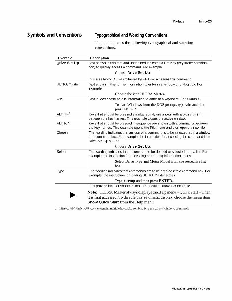
Symbols and Conventions Typographical and Wording Conventions
This manual uses the following typographical and wording conventions:
Example DescriptionDrive Set Up Text shown in this font and underlined indicates a Hot Key (keystroke combina-
tion) to quickly access a command. For example,
Choose Drive Set Up.
indicates typing ALT+D followed by ENTER accesses this command.
ULTRA Master Text shown in this font is information to enter in a window or dialog box. For example,
Choose the icon ULTRA Master. win Text in lower case bold is information to enter at a keyboard. For example,
To start Windows from the DOS prompt, type win and then press ENTER.
ALT+F4a Keys that should be pressed simultaneously are shown with a plus sign (+) between the key names. This example closes the active window.
ALT, F, N Keys that should be pressed in sequence are shown with a comma (,) between the key names. This example opens the File menu and then opens a new file.
Choose The wording indicates that an icon or a command is to be selected from a window or a command box. For example, the instruction for accessing the command icon Drive Set Up states:
Choose Drive Set Up.Select The wording indicates that options are to be defined or selected from a list. For
example, the instruction for accessing or entering information states:
Select Drive Type and Motor Model from the respective list box.
Type The wording indicates that commands are to be entered into a command box. For example, the instruction for loading ULTRA Master states:
Type a:setup and then press ENTER. Tips provide hints or shortcuts that are useful to know. For example,
Note: ULTRA Master always displays the Help menu – Quick Start – whit is first accessed. To disable this automatic display, choose the menu Show Quick Start from the Help menu.
a. Microsoft® Windows™ reserves certain multiple keystroke combinations to activate Windows commands.
Publication 1398-5.2 – PDF 1997
Intro-24 Preface
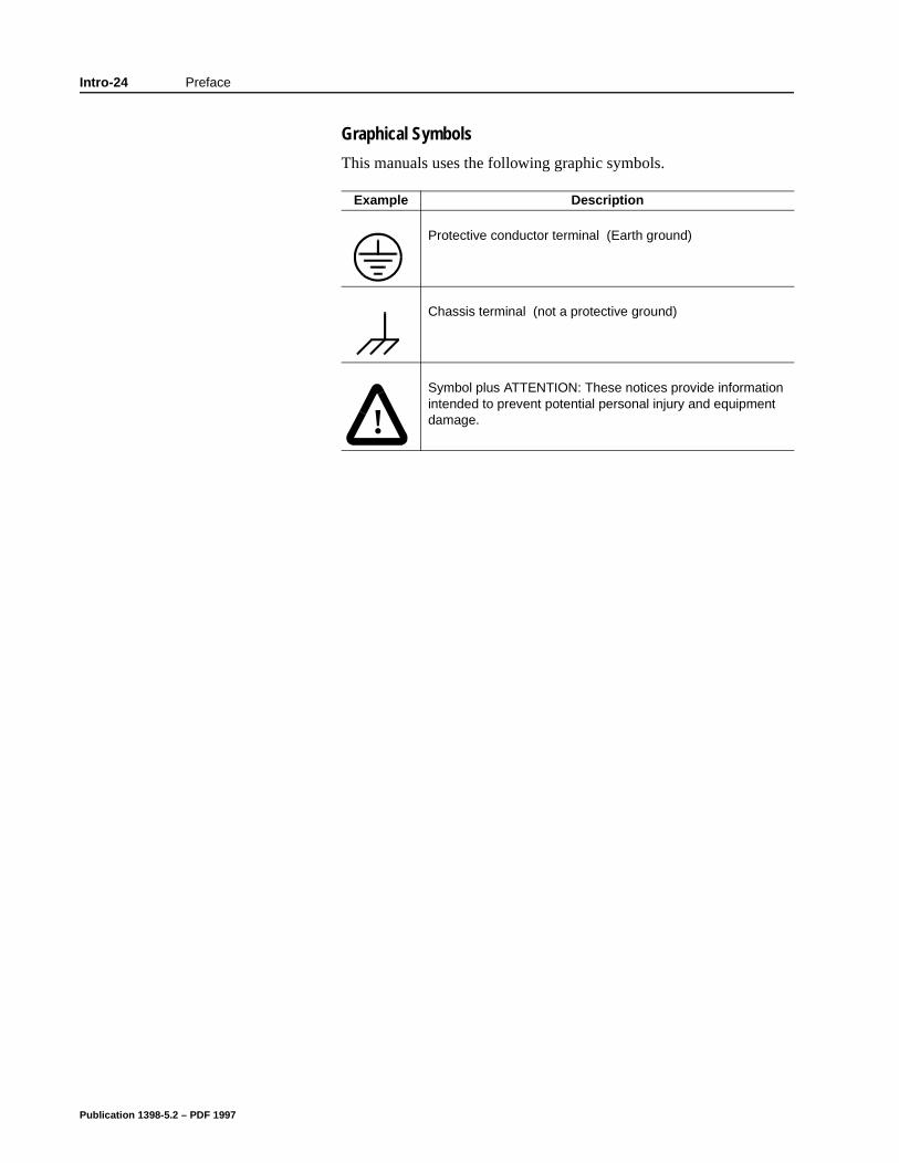
Graphical Symbols
This manuals uses the following graphic symbols.
Example Description
Protective conductor terminal (Earth ground)
Chassis terminal (not a protective ground)
!Symbol plus ATTENTION: These notices provide information intended to prevent potential personal injury and equipment damage.
Publication 1398-5.2 – PDF 1997
Preface Intro-25
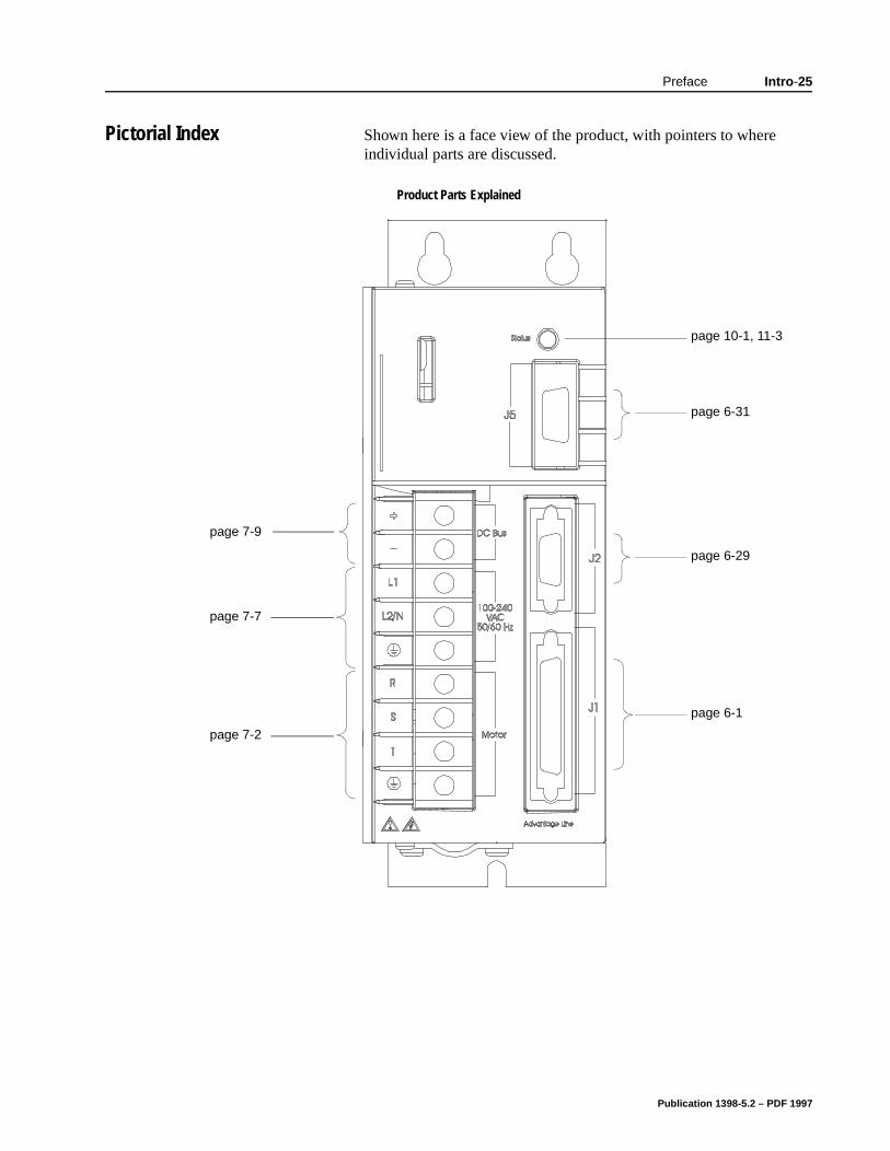
Pictorial Index Shown here is a face view of the product, with pointers to where individual parts are discussed.
Product Parts Explained
page 7-2
page 7-7
page 7-9
page 6-31
page 6-29
page 6-1
page 10-1, 11-3
Publication 1398-5.2 – PDF 1997

Intro-26 Preface
Publication 1398-5.2 – PDF 1997

Chapter 1
re:
Safety Chapter 1
Installing and Using the ULTRA 100 Series Drive
Read the complete manual before attempting to install or operate the drive. By reading the manual you will become familiar with practices and procedures that allow you to operate the drive safely and effectively.
You should always adhere to the “General Safety Guidelines” on page 1-3. Specific Warnings and Cautions appear throughout the manual.
Potential Hazards
The equipment described in this manual is intended for use in industrial drive systems. This equipment can endanger life throughrotating machinery and high voltages, therefore it is essential that guards for both electrical and mechanical parts are not removed.
Hazards which can be encountered in the use of this equipment a
Electric Shock
Electric Fire
Mechanical
Stored Energy
These hazards must be controlled by safe machine design, using specific local regulations, normal safety guidelines and the specificnotices that follow. There are no chemical or ionizing radiation hazards.
Publication 1398-5.2 – PDF 1997
1-2 Safety
e
n. r
d
e
al or . As pt
ry to
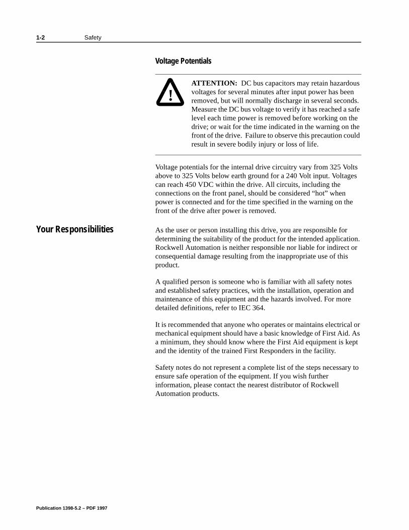
Voltage Potentials
Voltage potentials for the internal drive circuitry vary from 325 Volts above to 325 Volts below earth ground for a 240 Volt input. Voltages can reach 450 VDC within the drive. All circuits, including the connections on the front panel, should be considered “hot” when power is connected and for the time specified in the warning on thfront of the drive after power is removed.
Your Responsibilities As the user or person installing this drive, you are responsible for determining the suitability of the product for the intended applicatioRockwell Automation is neither responsible nor liable for indirect oconsequential damage resulting from the inappropriate use of thisproduct.
A qualified person is someone who is familiar with all safety notesand established safety practices, with the installation, operation anmaintenance of this equipment and the hazards involved. For mordetailed definitions, refer to IEC 364.
It is recommended that anyone who operates or maintains electricmechanical equipment should have a basic knowledge of First Aida minimum, they should know where the First Aid equipment is keand the identity of the trained First Responders in the facility.
Safety notes do not represent a complete list of the steps necessaensure safe operation of the equipment. If you wish further information, please contact the nearest distributor of Rockwell Automation products.
!
Intro
ATTENTION: DC bus capacitors may retain hazardous voltages for several minutes after input power has been removed, but will normally discharge in several seconds. Measure the DC bus voltage to verify it has reached a safe level each time power is removed before working on the drive; or wait for the time indicated in the warning on the front of the drive. Failure to observe this precaution could result in severe bodily injury or loss of life.
Publication 1398-5.2 – PDF 1997
Safety 1-3
General Safety Guidelines This section covers general safety guidelines for electronic devices. Safety information specific to ULTRA 100 Series drives begins on page 1-1.
Hazards which can be encountered in the use of this equipment are:
Electric Shock
Electric Fire
Mechanical
Stored Energy
There are no chemical or ionizing radiation hazards.
Electrical shock and fire hazards are avoided by using normal installation procedures for electrical power equipment in an industrial environment. Installation must be undertaken by suitably qualified personnel. Note that this amplifier must be installed in an industrial cabinet such that access is restricted to suitable qualified personnel.
Mechanical hazards are associated with potentially uncontrolled movement of the motor shaft. If this imposes a risk in the machine, then appropriate precautions must be made to electrically disconnect the motor from the drive when personnel have access to moving parts of the machine. Note also that the motor must be securely mounted at all times.
Stored energy hazards are both electrical and mechanical.
1. Electrical hazards can be avoided by disconnecting the drive from its power source and measuring the DC bus voltage to verify it has reached a safe level or by waiting for the time indicated in the warning on the front of the drive prior to removing the protective covers or touching any connections.
2. Mechanical hazards require a risk analysis on the effects of stored mechanical energy when the machine is running at speed, as well as the potential for the conversion of electrical energy stored in the drive being converted to mechanical energy. Electrical energy may be stored in drive for the time indicated in the warning on the front of the drive.
The following points should be observed for the safety of personnel:
Only qualified personnel familiar with the equipment are permitted to install, operate and maintain the device.
System documentation must be available and observed at all times.
Publication 1398-5.2 – PDF 1997
1-4 Safety
All non-qualified personnel should maintain a safe distance from the equipment.
The system must be installed in accordance with local regulations.
The equipment is intended for permanent connection to a main power input. It is not intended for use with a portable power input.
Do not power up the unit without the covers in place and the protective conductor connected.
Do not operate the unit without connecting the motor conductor to the appropriate terminal on the drive.
Always remove power before making or removing any connection on the unit.
Before removing the cover of the unit, shut off the main power and measure the DC bus voltage to verify it has reached a safe level or wait for the time as indicated on the front of the drive.
Do not make any connections to the internal circuitry. Connections on the front panel are the only points where users should make connections.
Be careful of the DC bus and shunt terminals. High voltage is present when power is applied to the drive.
Never connect the DC- (negative) terminal to earth ground, the drive requires a floating DC bus.
Do not use the ENABLE input as a safety shutdown. Always remove power to a drive before maintaining or repairing the unit.
Motors without thermal protection devices require a valid thermal time constant. Otherwise the motor overload protection will not function properly.
Publication 1398-5.2 – PDF 1997
Chapter 2
we nit:
it.
r to d
ns cts.
Unpacking, Inspecting and StoringChapter 2
This chapter describes the steps which ensure that the drive will function as specified. The steps include:
Unpacking the ULTRA 100 Series drive
Inspecting the drive for shipping damage
Testing the basic functionality of the drive
Guidelines for storing the drive.
Unpacking the Drive 1. Remove the ULTRA 100 Series drive from the shipping carton and remove all packing materials from the unit. The materials and carton may be retained for storage or shipment of the drive.
2. Check all items against the packing list. A label located on the side of the unit identifies:
• model number
• serial number
• manufacturing date code.
Inspection Procedure To protect your investment and ensure your rights under warranty,recommend the following steps be performed upon receipt of the u
Inspect the unit for any physical damage that may have been sustained during shipment.
Perform the Inspections Test to verify the functionality of the un
If you find damage, either concealed or obvious, contact your buyemake a claim with the shipper. If degraded performance is detectewhen testing the unit, contact your distributor or Rockwell Automation to obtain a Return Material Authorization (RMA). Do this as soon as possible after receipt of the unit.
“Our Warranty” on page Help-7 summarizes the period and conditiounder which ULTRA 100 Series drives are warranted against defe
Publication 1398-5.2 – PDF 1997
2-2 Unpacking, Inspecting and Storing
e es.
the r he to be
on ll
es
d
Testing the Unit Drives are burned-in and individually tested before they leave the factory. However, damage may occur during shipping. Perform the procedures below to ensure the ULTRA 100 Series drive is operational and undamaged.
Abbreviated directions for connecting the drive to a motor and a PC are provided.
The test requires:
Approximately 20 minutes to complete
A motor with appropriate power and encoder cables
A PC with the ULTRA Master software package installed
An RS-232 communications cable
An external I/O power supply
A single phase 100-240 VAC, 50/60 Hz power source. Standard wall outlet power is suitable for verification testing of ULTRA 100 Series drives.
A test cable constructed from two normally open switches, several
pieces of 1.5 mm2 (16 AWG) wire and a mating connector. Connectors are listed in “Mating Connectors” on page A-6. ThAppendix “Options and Accessories” on page A-1 lists the cabl
During the test, power is removed several times. Always measureDC Bus voltage to verify the bus capacitors are fully discharged, owait for the time indicated in the warning on the front of the drive. Tbus capacitors must be fully discharged for the subsequent steps valid.
If problems arise during this procedure, refer to “Troubleshooting” page 11-3 and review other relevant sections in this manual, or cayour local distributor.
Hardware Set Up
Make the connections described below and shown in Figure 2.1. “Options and Accessories” on page A-1 lists the interconnect cablavailable from the factory.
1. Connect an external I/O power supply (12-24 VDC) to J1-5 anJ1-6, or J1-26 and J1-13.
!
Intro
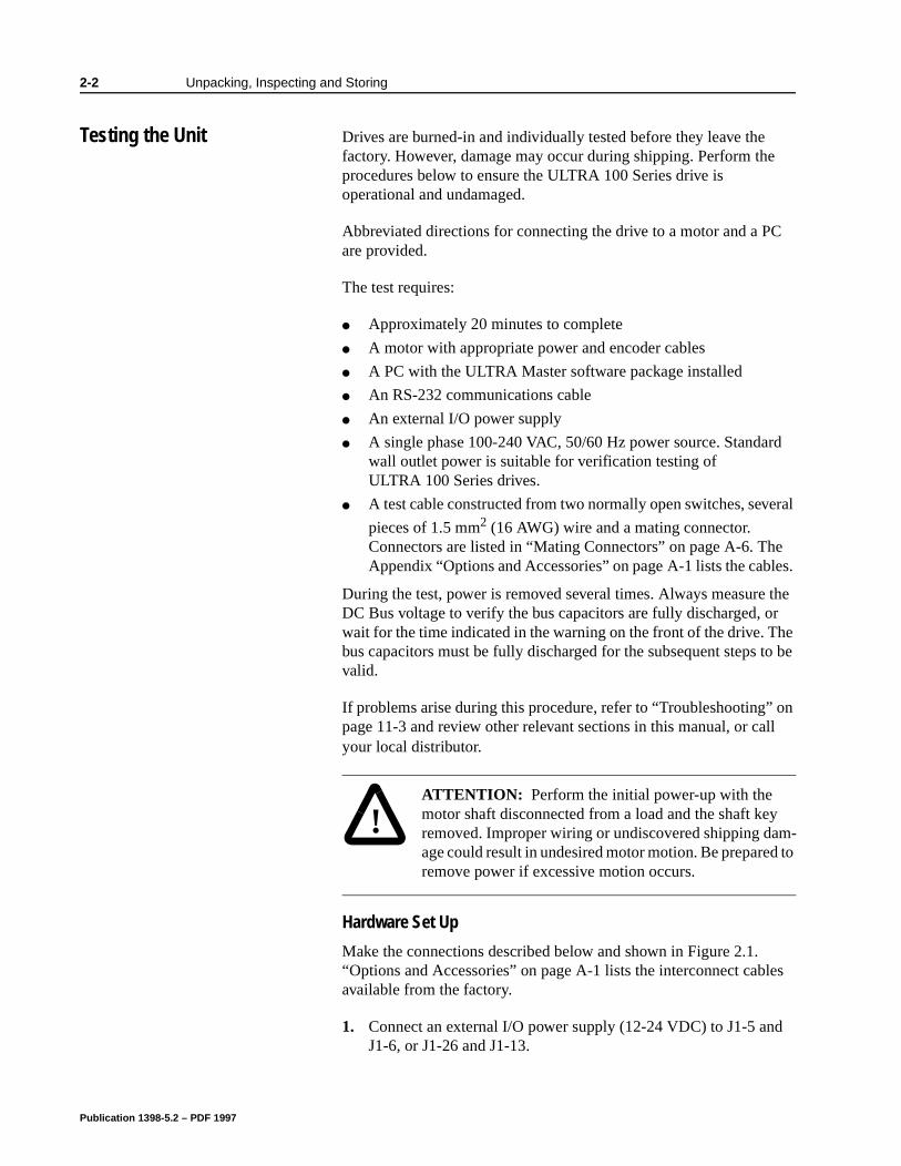
ATTENTION: Perform the initial power-up with the motor shaft disconnected from a load and the shaft key removed. Improper wiring or undiscovered shipping dam-age could result in undesired motor motion. Be prepared to remove power if excessive motion occurs.
Publication 1398-5.2 – PDF 1997
Unpacking, Inspecting and Storing 2-3
/60
.
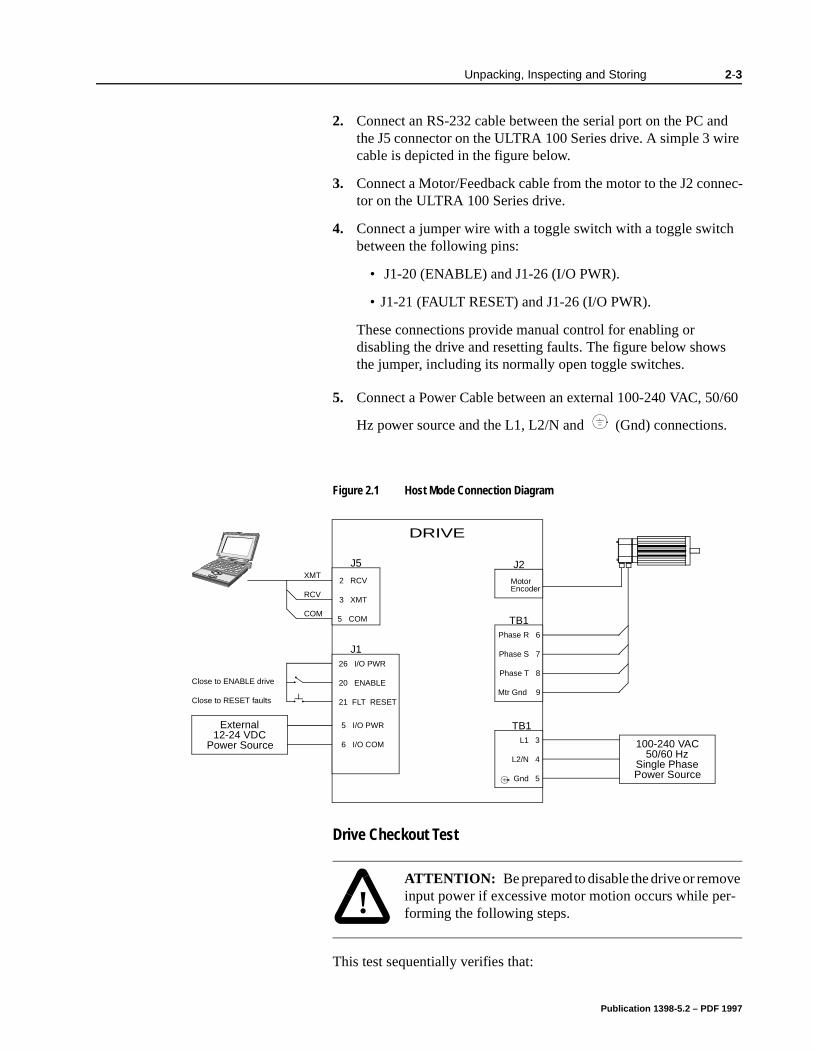
2. Connect an RS-232 cable between the serial port on the PC and the J5 connector on the ULTRA 100 Series drive. A simple 3 wire cable is depicted in the figure below.
3. Connect a Motor/Feedback cable from the motor to the J2 connec-tor on the ULTRA 100 Series drive.
4. Connect a jumper wire with a toggle switch with a toggle switch between the following pins:
• J1-20 (ENABLE) and J1-26 (I/O PWR).
• J1-21 (FAULT RESET) and J1-26 (I/O PWR).
These connections provide manual control for enabling or disabling the drive and resetting faults. The figure below showsthe jumper, including its normally open toggle switches.
5. Connect a Power Cable between an external 100-240 VAC, 50
Hz power source and the L1, L2/N and (Gnd) connections
Drive Checkout Test
This test sequentially verifies that:
Figure 2.1 Host Mode Connection Diagram
External12-24 VDC
Power Source
J5
DRIVE
J1
TB1
TB1
26 I/O PWR
20 ENABLE
21 FLT RESET
2 RCV
3 XMT
5 COM
Phase R 6
Phase S 7
Phase T 8
Mtr Gnd 9
L1 3
L2/N 4
Gnd 5
100-240 VAC50/60 Hz
Single Phase
XMT
RCV
COM
Close to ENABLE drive
Close to RESET faults
Power Source
J2
MotorEncoder
5 I/O PWR
6 I/O COM
!
Intro
ATTENTION: Be prepared to disable the drive or remove input power if excessive motor motion occurs while per-forming the following steps.
Publication 1398-5.2 – PDF 1997

2-4 Unpacking, Inspecting and Storing
:
Drive power wiring is correct and start-up logic is functioning.
The drive and motor are correctly wired
Drive serial communications are operational
Before beginning the “Initial Power-up”, please check the following
All wiring and mounting to verify correct installation
Input voltages to ensure they do not exceed specifications for the drive or motor.
Publication 1398-5.2 – PDF 1997

Unpacking, Inspecting and Storing 2-5
lay:
en
w
,
st
Initial Power-up
1. Verify the AC power is within specifications at the terminal strip.
2. Switch the AC Power to ON and verify the Status LED is green
3. Switch the power OFF and wait until the DC Bus Voltage is below 30 Volts.
4. Connect the motor windings to:
• R (TB1-6)for the Phase R winding
• S (TB1-7) for the Phase S winding
• T (TB1-8) for the Phase T winding
• (TB1-9) for the Ground connection.
5. If a brake motor is being used for the test, connect the brake re
• BRAKE ENABLE + (J1-49) to the Motor Brake +
• BRAKE ENABLE - (J1-50) to the Motor Brake -.
6. Switch AC Power ON again and verify the STATUS LED is gre
7. Switch the power OFF and wait until the DC Bus Voltage is belo30 Volts.
Communications Verification
8. Start ULTRA Master on the PC.
9. Close any windows that are open in ULTRA Master.
10. Select PC Set Up from the Communications menu in ULTRA Master.
11. Verify the communication port settings match those of the drivethen select OK. Factory default drive settings are:
• Baud Rate: 9600
• Data Bits: 8
• Parity: None
• Stop Bits: 1
• Serial Port: COM1
Assignment of communications ports on PCs varies between manufacturers. The COM port setting for the drive and PC mumatch. Refer to “Troubleshooting” on page 11-3 if communication problems are encountered.
12. Switch AC power ON.
Publication 1398-5.2 – PDF 1997
2-6 Unpacking, Inspecting and Storing
13. Select Read Drive Parameters from the Communications menu in ULTRA Master.
14. Select OK in the Drive Select dialog box. A dialog box indicating that the PC is reading drive parameters should appear.
If this dialog box does not appear, a message appears that advises you to check the COM settings and the communication cable. If necessary, refer to “Troubleshooting” on page 11-3 for instructions on how to perform these checks.
Publication 1398-5.2 – PDF 1997
Unpacking, Inspecting and Storing 2-7
e
on 4
ce.)
rive.
Initial Drive Operation
1. When the message appears that a motor must be selected, choose OK. The Drive Set Up dialog box is selected with Motor Model active.
2. Select the appropriate motor from the drop-down Motor Model box.
3. Choose OK when the message appears advising that the drive must reset. A change in motor parameters requires reselection of the firmware based drive/motor tables. The software reset pre-vents improper sequencing of these table parameters.
4. Choose Close from the Drive Set Up window.
5. Select the Control Panel icon from the Drive Window.
6. Close the connection between J1-26 and J1-20 to enable the drive.
7. Holding torque should be sufficient so that the shaft is either immovable or very resistant to rotation.
8. Move the Slide Bar in the Control Panel window to the right and then to the left. Verify that the motor rotates:
• CW as the Slide Bar is moved right of center, and
• CCW as the Slide Bar is moved left of center.
If the motor rotates in the wrong direction (CCW when the slidbar is set to the right of center) or jumps and locks-up, motor phasing and encoder feedback phasing may be incorrect. If necessary, refer to the Troubleshooting chapter for instructionshow to correct the motor power connections at TB1-1, 2, 3 andor the encoder feedback connections at J2.
9. Choose Set to Zero. The motor will stop rotating.
10. Choose Drive Disable and verify the motor shaft can be rotatedby hand.
11. Choose Drive Enable and verify the motor shaft has holding torque. (i.e., The shaft cannot be moved or moves with resistan
12. Open the connection between J1-26 and J1-20 to disable the d
13. Choose Close from the Control Panel window.
Publication 1398-5.2 – PDF 1997
2-8 Unpacking, Inspecting and Storing
na-
A drive completing these steps is functional. If the ULTRA 100 Series drive did not pass the steps above, refer to “Troubleshooting” on page 11-3.
Storing the Unit
Return the drive to its shipping carton using the original packing materials to enclose the unit.
Store the drive in a clean, dry place that will not exceed the following ranges:
Humidity: 5% to 95%, non-condensing
Storage temperature: -40° to 158° Fahrenheit (-40° to 70° Celsius).
Note: For information on testing the digital and analog signals refer to “Testing Digital Outputs” on page 11-9, “Testing Digital Inputs” on page 11-11, “Testing Analog Output” on page 11-11 and “Testing Alog Input” on page 11-12.
Publication 1398-5.2 – PDF 1997
Chapter 3
Selecting Other System Components Chapter 3
This chapter reviews the ULTRA 100 Series 1398-DDM-005 and -005X, 1398-DDM-009 and -009X, 1398-DDM-019 and -019X drives, command sources and interfaces for the drives, and complementary motors and accessory equipment. Selection of complementary servo components allows you to efficiently connect other devices to your microdrive. Pertinent information about each is provided to assist you in planning your servo system.
ULTRA 100 Series Overview The ULTRA 100 Series drives are part of a family of universal digital drives. ULTRA 100 Series drives use microcontrollers to digitally manage the current, velocity, and position. All system and application parameters are set in software, which ensures repeatability of all functions and prevents element drift.
A single unit fully encloses all electronics. An external transformer is not required on the power line. All connectors and indicators are accessible and clearly marked on the front panel.
ULTRA 100 Series Features Drive Power Ratings
Several power levels of ULTRA 100 Series drives are available. All
models have integral power supplies1 and use a single phase power source. They differ only in physical size, indexing capability and output power:
1398-DDM-005 and -005X with continuous output power of 500 Watts.
1398-DDM-009 and -009X with continuous output power of 1000 Watts.
1398-DDM-019 and -019X with continuous output power of 2000 Watts.
The ULTRA 100 Series drives, when combined with brushless servo motors, provide continuous torque ranging from 0.17 Nm to 2.5 Nm (1.5 to 22.5 lb-in) and peak torque ranging from 0.48 Nm to 7.12 Nm (4.3 lb-in to 63 lb-in).
1. 1398-DDM-005 and -005X, 1398-DDM-009 and -009X, 1398-DDM-019 and -019X require an external 12-24VDC power source for I/O.
Publication 1398-5.2 – PDF 1997
3-2 Selecting Other System Components
on
or
l
4
High Performance Microcontroller Technology
All digital current, velocity and position loop calculations as well as the motor commutation calculation are performed by a microcontroller.
IPM Technology
IPM (Intelligent Power Module) technology in the output stage provides a high frequency, digital PWM (Pulse Width Modulation) sine wave that controls the current loop, including overcurrent, short circuit and overtemperature protection.
Analog and Digital Interfaces
All ULTRA 100 Series drives allow the user to select one of the following analog or digital command interfaces:
±10 Volt analog interface - velocity or torque control
Presets (from one to eight binary inputs) - torque or velocity control
Quadrature encoder digital interface - electronic gearing positifollower
Step/Direction digital interface - position control
CW/CCW (step up/step down) interface - position control
Indexing - position control from a single point in one of three ways
Operating mode override - alternate movement interface
Encoder Control
A single, motor mounted encoder provides complete commutationinformation and velocity feedback. Low velocity regulation is enhanced by the use of a 5000 PPR (pulses per revolution) incremental encoder.
Encoder Output
A selectable output allows the encoder resolution to be specified fmaximum performance without added circuitry. Outputs are differential line drivers capable of dividing the motor encoder signaby a factor of 1, 2, 4 or 8.
Digital I/O
Digital I/O channels allow the user to program the drive to fit the specific application. Power for the I/O must be supplied by an 12-2VDC external I/O power source. Selections include:
Four selectable (INPUT1, INPUT2, INPUT3 and FAULT RESET), optically isolated, active high inputs.
Publication 1398-5.2 – PDF 1997
Selecting Other System Components 3-3
s for
d
e
l
One dedicated, control (ENABLE), optically isolated, active high input.
Two selectable, optically isolated and short circuit protected, active high outputs.
Two dedicated (BRAKE/DRIVE ENABLED and DRIVE READY), normally open relay outputs.
Analog I/O
A dedicated analog input provides current limiting capabilities, while the analog output can be customized to fit the application:
One dedicated 0 - 10 Volt, analog input (EXTERNAL CURRENT LIMIT)
One selectable, ±10 Volt analog output.
AC Input Power
ULTRA 100 Series drives covered by this manual are powered directly from a main 100-240 VAC single phase line.
Personality Module
EEPROM (electrically erasable programmable read only memory)stores both motor and application specific settings and parameterthe drive.
Multiple Protection Circuits
Device and circuit protection, and diagnostic information is provideby:
Bi-color single point LED
Overtemperature, short circuit and overcurrent protection for thpower output
I2T (power-time) protection for the motor and the power drive
Bus Overvoltage
Bus Undervoltage
Overspeed
Fault diagnostics
Watchdog timers provide fail-safe operation.
Command Sources Serial Command Sources
ULTRA 100 Series drives are configured and controlled via a seriacommunication link. Commands may be issued from a variety of sources through a serial communications port. Possible commandsources include:
Personal computers
Publication 1398-5.2 – PDF 1997
3-4 Selecting Other System Components
ires e
ic a
the wn t 5
f
mA
put
d.
Host computers
Programmable Logic Controllers
Motion controllers
TouchPad.
The serial communication interface for the ULTRA 100 Series supports:
RS-232 and the four wire RS-485 communications standards
NRZ (non-return to zero) asynchronous serial format
Baud rates: 1200, 2400, 4800, 9600 and 19200
Parity generation and checking: Even, Odd or None.
Connection of communication cables between the drive and user-supplied equipment is described in the following sections:
One ULTRA 100 Series drive - “Single Axis RS-232 Set Up” onpage 6-34
Multiple ULTRA 100 Series drives - “Multiple Axes Four-wire RS-485 Communications” on page 6-35.
Analog Command Sources
In the analog mode of operation, the ULTRA 100 Series drive requa variable ±10 Volt DC external analog signal capable of driving thservo regulator’s command input at an input impedance of 13.3 kOhms. Choose a source such as a PLC (programmable logcontroller), the DAC (digital-to-analog converter) of a computer, ormotion controller that meets this requirement.
Differential or single-ended line drivers may supply the signals for auxiliary encoder inputs, step and direction inputs, and step up/doinputs. The differential signal must be capable of supplying at leasmA with 2.0 Volts across the + and - inputs. A differential signal source provides the best noise margin of all the interface circuit options. Single-ended signals from TTL drivers must be capable osourcing or sinking 5 mA.
In preset mode, the controlling device should be able to source 10into the digital inputs.
I/O Interface Analog Input
One analog input channel is accessible to the user. The analog inlimits the peak current available from the drive.
I LIMIT (current limit)
The analog signal must be within 0-10 Volt range and single-ende
Publication 1398-5.2 – PDF 1997
Selecting Other System Components 3-5
e
y
l
s.
If this signal is not provided, the peak current of the drive may be set in software through the Drive Parameter window.
Analog Output
One analog output channel may be defined by the user through software:
ANALOG is a ±10 Volt signal. The allowable current draw of thload is ±2 mA
This analog output is designed for monitoring purposes only. This signal should not be used for control purposes due to the relativelhigh ripple voltage (1%).
Digital Inputs
Control Inputs
One optically isolated, single ended, active high, dedicated controinput provides the controller ENABLE function. This input operateswith switch closure or sourcing type transistor outputs.
The current rating is 10 mA maximum.
Selectable Inputs
Four optically isolated, single ended, active high inputs (INPUT1, INPUT2, INPUT3 and FAULT RESET) support logic type interfaceThe input circuits operate with switch closure or sourcing type transistor circuits.
The current rating of each input is 10 mA maximum.
Digital Outputs
Control Outputs
Two normally open relays are dedicated control outputs to the following signals:
BRAKE/DRIVE ENABLED
DRIVE READY.
The current ratings of each relay is 1 Amp at 30 VDC.
Note: Power for the I/O must be supplied by an external 12-24 VDC power source.
Publication 1398-5.2 – PDF 1997
3-6 Selecting Other System Components
If using a motor with the 90VAC brake option, a user-provided relay may be driven by these outputs up to the specified levels. Refer to Figure 6.10 on page 6-10 for information about the necessary hardware connections. Consult the I/O Configuration in the on-line ULTRA Master help for additional information about the software parameters.
Selectable Outputs
Two optically isolated, single ended, active high, current sourcing, discrete output channels provide logic outputs under software control.
Each selectable output channel is capable of sourcing 50 mA maximum and is optically isolated and short circuit protected.
Auxiliary Encoder Interface
The external encoder I/O port permits quadrature type encoder signals for applications, such as electronic gearing.
Encoder Inputs
Software automatically selects the appropriate input based on the command source:
Master Encoder
Step/Direction
Step Up/Step Down.
Encoder Output
The resolution of the encoder output channel is under software control. The motor encoder signal is divided by 1, 2, 4 or 8 to provide an output from a differential line driver measured in PPR (pulses per revolution). The maximum encoder frequency output is 1 MHz (4 MHz quadrature).
ULTRA Master Software A Windows-based software interface provides start-up selections. Tasks are organized for efficient set up, control and maintenance. Context sensitive, on-line help provides immediate assistance.
Set up is simplified by a series of logically arranged set up screens.
Files can be stored and printed for on-line or off-line modification, and on-site or off-site back-up.
Diagnostic and set up tools make system integration easy.
Note: If a controller requires synchronization to a specific output state, refer to “IOUT Signal Generation” on page 6-18 for additional information.
Publication 1398-5.2 – PDF 1997
Selecting Other System Components 3-7
s ory
into
ed
Critical information is available with complete Windows-based on-line help.
Serial Host Language commands are explained through on-line help.
User defined velocity, acceleration, position and torque parameters.
Tuning and diagnosis is aided with an on-screen dual channel digital oscilloscope.
On-screen meters and software tools provide rapid debugging and measurement.
Autotuning
Digital auto tuning allows easy setup. All adjustments are made in software, which immediately sets the servo system compensation parameters. This eliminates the time-consuming adjustments required by potentiometers.
Agency Approvals UL listed
cUL listed
CE marked.
Interface Cables Standard motor power and encoder feedback cables, as well as communications cables, are available to complete your motion control system and provide reliable, trouble free start-up. Refer to “Optionand Accessories” on page A-1 for optional equipment. Use of factsupplied cables is required for compliance to the European Electromagnetic Compatibility (EMC) Directive and to protect yourwarranty rights.
Motors The ULTRA 100 Series is compatible with many motors, both Allen-Bradley motors and motors from other manufacturers. Drive and motor parameters for all compatible motors are programmed each ULTRA 100 Series drive at the factory. Allen-Bradley motorsthat are compatible with the ULTRA 100 Series drives include:
F-Series motors
H-Series motors
N-Series motors
W-Series motors
Y-Series motors.
ULTRA Master software speeds drive and motor set up by predefinparameters for each drive and motor combination.
Publication 1398-5.2 – PDF 1997

3-8 Selecting Other System Components
d,
Refer to the Torque/Speed curves in the Allen-Bradley Standard Product Catalog and Handbook (Publication 1398-2.0) or contact your local Allen-Bradley distributor for motor sizing and compatibility assistance.
Custom motors or motors not manufactured by Allen-Bradley may be interfaced, refer to “Creating Custom Motor Files” on page D-1 anif necessary, contact Product Support for assistance.
Options
Power and feedback cables are potted and molded with 360 degree shielding.
AC line filters.
Breakout boards for I/O control and encoder interface.
TouchPad - a compact and highly portable input and display device.
Publication 1398-5.2 – PDF 1997
Selecting Other System Components 3-9
n --
CE
European Union Requirements
ULTRA 100 Series drives conform to the following European Union Directives:
Low Voltage Directive (72/23/EEC, 93/68/EEC)
Electromagnetic Compatibility Directive (89/336/EEC, 92/31/EEC, 93/68/EEC)
Compliance with the EEC Directives is contingent on two conditions:
1. Installation of AC line filters between the power source and the drive, and
2. Use of factory authorized cables to connect motors. “EuropeaUnion EMC Directives” on page 5-7 and “Options and Accessories” on page A-1 lists this equipment and associated part numbers.
Use of this product with other non-CE products or in a manner inconsistent with established testing requirements invalidates the registration declaration.
Allen-Bradley motors currently available for use with ULTRA 100 Series drives in installations requiring CE marking include:
F-Series motors
H-Series motors
LD-Series motors
S-Series motors
Y-Series motors
Publication 1398-5.2 – PDF 1997
Chapter 4
ws
l-
e -
ULTRA Master Installation Chapter 4
Installation of ULTRA Master on a PC is covered in this chapter, which:
Lists the minimum PC hardware and software necessary to run ULTRA Master.
Provides step-by-step instructions on how to load ULTRA Master.
Shows you how to start and quit ULTRA Master and introduces the Drive Window, the main command window for ULTRA Master.
Instructs you on how to access on-line help.
Instructions for using the features available in ULTRA Master are detailed in on-line help. To access the Help menu, depress the F1 key.
Hardware and Software Requirements
The minimum personal computer (PC) requirements to run the software are:
A DOS computer with a 286 microprocessor
A hard disk, with 2.0 MB of free disk space
3½ inch, 1.44MB floppy disk drive
2 MB of RAM
A Video Graphics Array (VGA) monitor
Microsoft Windows version 3.1
A mouse is recommended.
Windows must be installed on your PC. If Windows is not already installed, refer to the appropriate Microsoft manual to install Windoon your computer.
Installing ULTRA Master To install ULTRA Master software on a hard drive:
1. Make a backup copy of the ULTRA Master disk in one of the folowing ways:
• Copy the ULTRA Master disk using the disk menu in the Windows File Manager.
• If your computer has only one floppy disk drive, type from the DOS command line prompt diskcopy a: b: and then press ENTER. The software will prompt you when to insert thSOURCE (ULTRA Master) disk and when to insert the TARGET (blank) disk.
Publication 1398-5.2 – PDF 1997
ULTRA Master Installation 4-2
.
.
d
2. If Windows is not running, type win at the DOS prompt (C:>). If Windows is already running, close any open applications.
3. Insert the ULTRA Master disk into a 1.44MB floppy disk drive, typically drive A:, and close the drive door.
4. Choose Run, from the File menu in Windows Program Manager.
5. Type a:setup and then press ENTER. A message box will appear saying that the setup is initializing. The message box may be present for up to 40 seconds, depending on the speed of the PC.
6. A dialog box requires you to confirm whether or not ULTRA Master should be installed on the hard drive (C: drive) of the PC.
• To install ULTRA Master, choose Continue, or press ENTER, and continue with the next step.
• To stop the installation, choose Exit. You are returned to Win-dows.
7. Setup then asks where you would like to install ULTRA Master
• To accept the path that Setup proposes in the Path: box (c:\ultramst\...), choose Continue,
• To choose another directory, type a new path in the Path: box, and then choose Continue. You will not have the opportunity to confirm your entry so type carefully.
• To return to the initial Setup window, choose Back.
• To stop the installation, choose Exit. You will return to Win-dows.
• To obtain on-line help with the installation, Choose Help.
8. A status bar will keep you informed of the installation progressWhen Setup is complete, choose OK or press ENTER to return to Windows.
Starting and Quitting ULTRA Master
Setup automatically creates the ULTRA Master program group anthen returns you to Windows. The ULTRA Master program group provides access to the ULTRA Master application icon,
From the C:> Prompt
1. Type win c:\ultramst\ultramst.exe.
The ULTRA Master start-up screen will open.
Note: This step assumes ULTRA Master was loaded into the c:\ultramst directory during setup.
Publication 1398-5.2 – PDF 1997
4-3 ULTRA Master Installation
From Windows
1. Choose the ULTRA Master program group from the Program Manager in Windows.
2. Choose the ULTRA Master icon from the ULTRA Master pro-gram group.
The ULTRA Master start-up screen will open.
Note: If the ULTRA Master window is not active, hold down ALT and press TAB (ALT+TAB) until the ULTRA Master title bar and icon are highlighted, or select ULTRA Master from the list in the Window menu.
Publication 1398-5.2 – PDF 1997
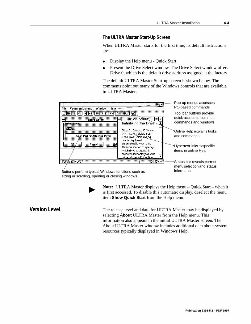
ULTRA Master Installation 4-4
it enu
The ULTRA Master Start-Up Screen
When ULTRA Master starts for the first time, its default instructions are:
Display the Help menu - Quick Start.
Present the Drive Select window. The Drive Select window offers Drive 0, which is the default drive address assigned at the factory.
The default ULTRA Master Start-up screen is shown below. The comments point out many of the Windows controls that are available in ULTRA Master.
Version Level The release level and date for ULTRA Master may be displayed by selecting About ULTRA Master from the Help menu. This information also appears in the initial ULTRA Master screen. The About ULTRA Master window includes additional data about system resources typically displayed in Windows Help.
Note: ULTRA Master displays the Help menu – Quick Start – whenis first accessed. To disable this automatic display, deselect the mitem Show Quick Start from the Help menu.
Tool bar buttons provide quick access to common commands and windows
Hypertext links to specific items in online Help
Status bar reveals current menu selection and status informationButtons perform typical Windows functions such as
sizing or scrolling, opening or closing windows.
4XLFN6WDUW
Pop-up menus accesses PC-based commands
Online Help explains tasks and commands
Publication 1398-5.2 – PDF 1997
4-5 ULTRA Master Installation
Miscellaneous Files The readme File
A file, titled README, may be included in the ULTRA Master directory. This file contains installation instructions, change notes from previous revisions, and information that became available after this manual was printed. After you install ULTRA Master you can access this file by choosing the Read Me icon in the ULTRA Master window or by using Microsoft Write or an equivalent application program to view the file readme.wri in the directory path where ULTRA Master is installed.
Firmware Files
Firmware files are supplied in the Miscellaneous directory on the ULTRA Master diskette. The current revision level of drive firmware, excluding the TouchPad firmware, is displayed in the Drive Information window of ULTRA Master. The current revision level of TouchPad firmware is displayed as part of the TouchPad initialization when a TouchPad is connected to the drive.
The types of files and their functions are:
Firmware – Main Operating firmware for the drive
Boot Block – Drive Initialization firmware for the drive
Publication 1398-5.2 – PDF 1997
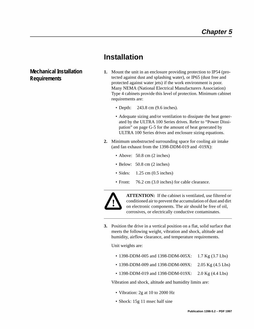
Chapter 5
er-i-
e
at
)
Installation Chapter 5
Mechanical Installation Requirements
1. Mount the unit in an enclosure providing protection to IP54 (pro-tected against dust and splashing water), or IP65 (dust free and protected against water jets) if the work environment is poor. Many NEMA (National Electrical Manufacturers Association) Type 4 cabinets provide this level of protection. Minimum cabinet requirements are:
• Depth: 243.8 cm (9.6 inches).
• Adequate sizing and/or ventilation to dissipate the heat genated by the ULTRA 100 Series drives. Refer to “Power Disspation” on page G-5 for the amount of heat generated by ULTRA 100 Series drives and enclosure sizing equations.
2. Minimum unobstructed surrounding space for cooling air intak(and fan exhaust from the 1398-DDM-019 and -019X):
• Above: 50.8 cm (2 inches)
• Below: 50.8 cm (2 inches)
• Sides: 1.25 cm (0.5 inches)
• Front: 76.2 cm (3.0 inches) for cable clearance.
3. Position the drive in a vertical position on a flat, solid surface thmeets the following weight, vibration and shock, altitude and humidity, airflow clearance, and temperature requirements.
Unit weights are:
• 1398-DDM-005 and 1398-DDM-005X: 1.7 Kg (3.7 Lbs)
• 1398-DDM-009 and 1398-DDM-009X: 2.05 Kg (4.5 Lbs
• 1398-DDM-019 and 1398-DDM-019X: 2.0 Kg (4.4 Lbs)
Vibration and shock, altitude and humidity limits are:
• Vibration: 2g at 10 to 2000 Hz
• Shock: 15g 11 msec half sine
!
Intro
ATTENTION: If the cabinet is ventilated, use filtered or conditioned air to prevent the accumulation of dust and dirt on electronic components. The air should be free of oil, corrosives, or electrically conductive contaminates.
Publication 1398-5.2 – PDF 1997

5-2 Installation
m
re:
. ed
• Altitude: 1500 meters (5000 feet), Derate power performance 3% for each 300 m above 1500(1000 ft above 5000 ft).
• Humidity: 5% to 95% non-condensing
Ambient operating temperature range and airflow clearances a
• 0 ° to 55° Celsius (32° to 131° Fahrenheit).
• 50.8 mm (2 inches) above and below unit for airflow.
4. Bolt the unit to the cabinet using the mounting slots in the driveMounting dimensions are shown in Figure 5.2. The recommendsize of mounting hardware is:
• M5 Metric (1/4-20 equivalent), or
• #10 MS bolts
Publication 1398-5.2 – PDF 1997
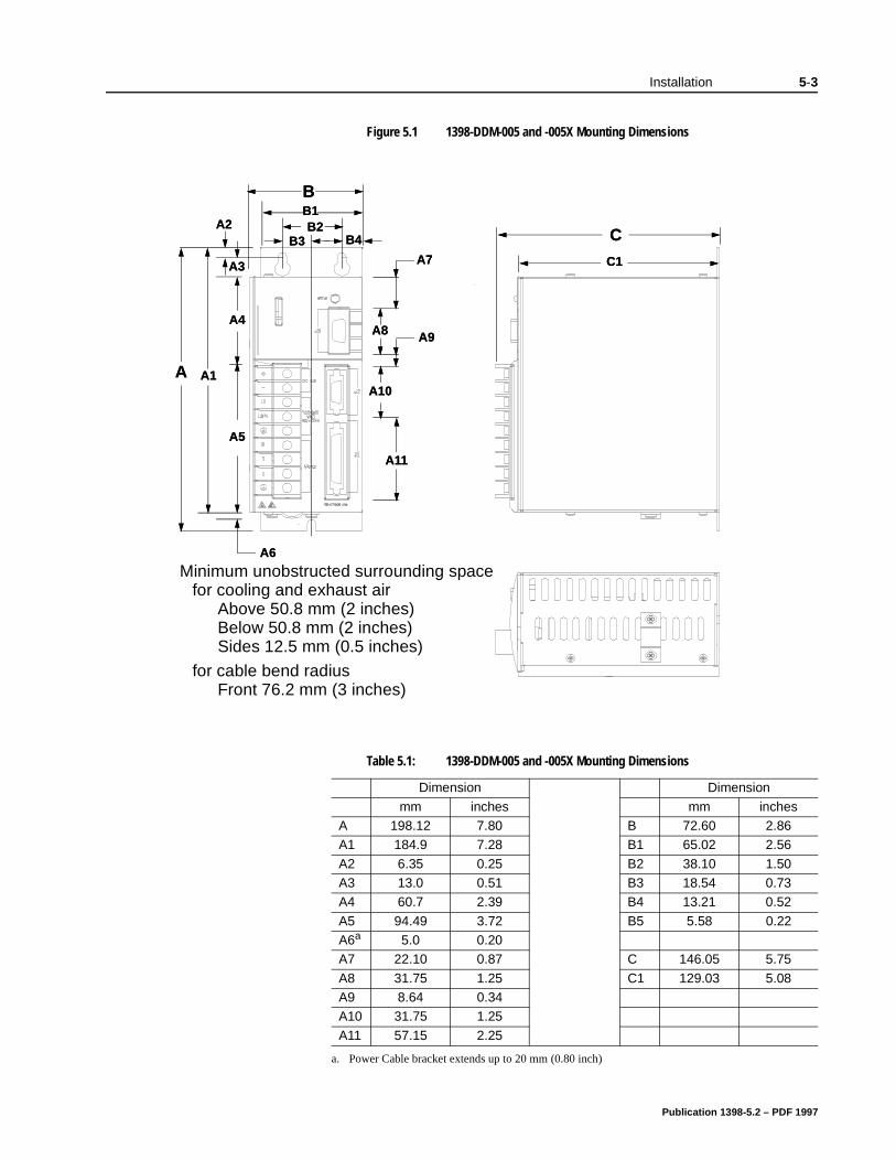
Installation 5-3
Figure 5.1 1398-DDM-005 and -005X Mounting Dimensions
Table 5.1: 1398-DDM-005 and -005X Mounting Dimensions
Dimension Dimension
mm inches mm inchesA 198.12 7.80 B 72.60 2.86A1 184.9 7.28 B1 65.02 2.56
A2 6.35 0.25 B2 38.10 1.50A3 13.0 0.51 B3 18.54 0.73A4 60.7 2.39 B4 13.21 0.52
A5 94.49 3.72 B5 5.58 0.22A6a 5.0 0.20A7 22.10 0.87 C 146.05 5.75
A8 31.75 1.25 C1 129.03 5.08A9 8.64 0.34A10 31.75 1.25
A11 57.15 2.25
a. Power Cable bracket extends up to 20 mm (0.80 inch)
C
C1
BB1B2
B4B3
A A1
A2
A3
A4
A6
A7
A8 A9
A10
A11
A5
C
C1
BB1B2
B4B3
A A1
A2
A3
A4
A6
A7
A8 A9
A10
A11
A5
Minimum unobstructed surrounding spacefor cooling and exhaust air
Above 50.8 mm (2 inches)Below 50.8 mm (2 inches)Sides 12.5 mm (0.5 inches)
for cable bend radiusFront 76.2 mm (3 inches)
Publication 1398-5.2 – PDF 1997
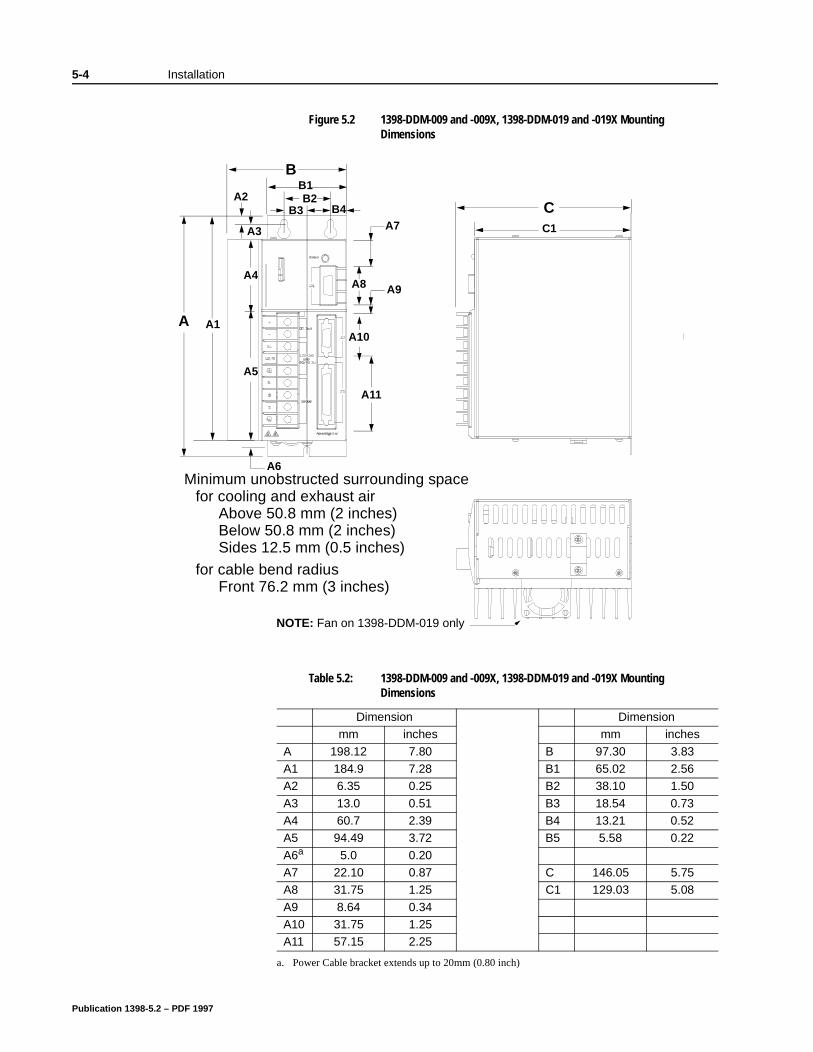
5-4 Installation
Figure 5.2 1398-DDM-009 and -009X, 1398-DDM-019 and -019X Mounting Dimensions
Table 5.2: 1398-DDM-009 and -009X, 1398-DDM-019 and -019X Mounting Dimensions
Dimension Dimensionmm inches mm inches
A 198.12 7.80 B 97.30 3.83A1 184.9 7.28 B1 65.02 2.56A2 6.35 0.25 B2 38.10 1.50
A3 13.0 0.51 B3 18.54 0.73A4 60.7 2.39 B4 13.21 0.52A5 94.49 3.72 B5 5.58 0.22
A6a 5.0 0.20A7 22.10 0.87 C 146.05 5.75A8 31.75 1.25 C1 129.03 5.08
A9 8.64 0.34A10 31.75 1.25A11 57.15 2.25
a. Power Cable bracket extends up to 20mm (0.80 inch)
A1
A2
A3
A4
A6
A5
CC1
BB1B2
B4B3
A
A7
A8 A9
A10
A11
Minimum unobstructed surrounding spacefor cooling and exhaust air
Above 50.8 mm (2 inches)Below 50.8 mm (2 inches)Sides 12.5 mm (0.5 inches)
for cable bend radiusFront 76.2 mm (3 inches)
NOTE: Fan on 1398-DDM-019 only
Publication 1398-5.2 – PDF 1997
Installation 5-5
s
rial
rove
e
Interface Connections Input/Output and power cables connect to the front panel of a ULTRA 100 Series drive, no internal connections are necessary.
I/O Connections, including the external I/O power supply, are fully described in the following sections:
“J1 – Controller” on page 6-1 defines the controller connection
“J2 – Encoder” on page 6-29 defines the motor encoder connections
“J5 – Serial Port” on page 6-31 defines the RS-232/RS-485 seport connections
Power Connections are fully described in the following sections:
Chapter 7, “Power Connections” defines the AC, DC Bus and Motor power connections.
Specific operational set ups are depicted in Figure 8.1 through Figure 8.11 (pages 8-2 through 8-45, respectively). These figures cover velocity and torque mode controls for:
Analog Controllers in velocity or torque modes,
Preset Controllers in velocity or torque modes,
Position Followers using a Master Encoder,
Position Followers using a Step/Direction signal,
Position Followers using Step Up/Down signals,
Incremental Indexing over a specific distance,
Registration Indexing from a mark, or
Absolute Indexing to a home position.
Wiring
Wiring sizes and practices, as well as grounding and shielding techniques are described in the sections listed below. Refer to Chapter 7, “Power Connections”.
The descriptions represent common wiring practices and should psatisfactory in the majority of applications.
!
Intro
ATTENTION: Perform the initial power-up with the motor shaft disconnected from a load and the shaft key removed. Improper wiring or undiscovered shipping dam-age could result in undesired motor motion. Be prepared to remove power if excessive motion occurs.
Note: Cables, listed in Appendix A, “Options and Accessories”, arnot rated for continuous flexing.
Publication 1398-5.2 – PDF 1997

5-6 Installation
Minimum wire gages for power cables are listed in:
“Motor Power Contact and Wire Size Recommendations” on page 7-4,
“AC Input Power Sizing Requirements” on page 7-8.
Publication 1398-5.2 – PDF 1997
Installation 5-7
r
e
up-
C d.
r the rs ing
Electromagnetic Compatibility
General Guidelines
Refer to Appendix E, “Electromagnetic Compatibility Guidelines foMachine Design” for an in-depth discussion of electromagnetic compatibility (EMC) and electromagnetic interference (EMI).
European Union EMC Directives
The ULTRA 100 Series drives are designed and tested to meet thEuropean EMC Directive. Declarations of conformity, which enumerate the standards used, are included in the manual.
Installation requirements necessary to meet this directive are:
1. Use of factory supplied cables,
2. Use of an external AC line filter, and
3. If an external supply powers the I/O, grounding of this power sply is required.
Refer to Appendix A, “Options and Accessories” for part numbers.The following diagrams show the mounting dimensions for single phase AC Line Filters available from Rockwell Automation.
Table 5.3 shows a typical filter selection matrix for ULTRA 100 Series drives. All the filters identified below are manufactured by Schaffner or Roxburgh and are widely available. There are many Aline filter manufacturers whose filters can be successfully integrateRockwell Automation recommends Schaffner or Roxburgh filters based on our test results, but the machine builder is responsible fosuitability of the filter selection in a specific application. These filtecan be used for distributing power to multiple drives, rather than usan individual filter for each drive. Further information is available from Schaffner (1-800-367-5566) or Roxburgh (01724.281770 [011.44.1724.281770 from the USA]).
AC line filters for use with ULTRA 100 Series drives are listed in Table 5.3.
!
Intro
ATTENTION: Large leakage currents exist in AC line filters. They must be grounded properly before applying power. Filter capacitors retain high voltages after power removal. Before handling the equipment, voltages should be measured to determine safe levels prior to handling the equipment. Failure to observe this precaution could result in severe bodily injury.
Publication 1398-5.2 – PDF 1997
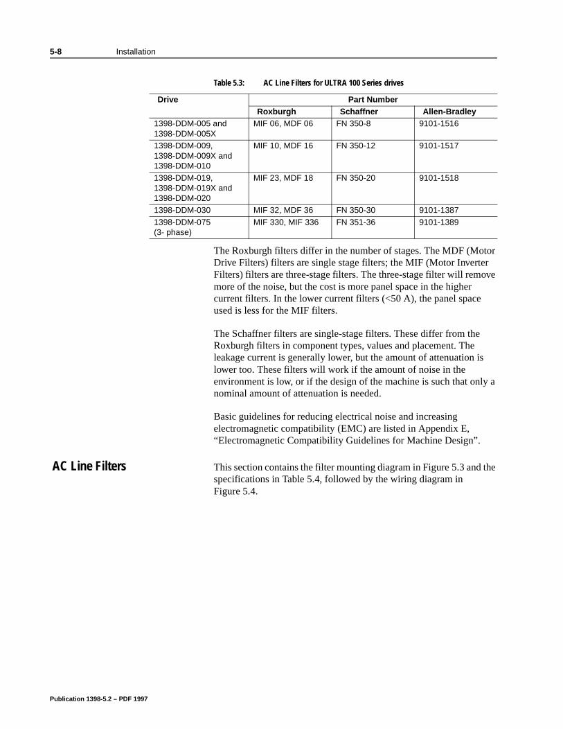
5-8 Installation
the
The Roxburgh filters differ in the number of stages. The MDF (Motor Drive Filters) filters are single stage filters; the MIF (Motor Inverter Filters) filters are three-stage filters. The three-stage filter will remove more of the noise, but the cost is more panel space in the higher current filters. In the lower current filters (<50 A), the panel space used is less for the MIF filters.
The Schaffner filters are single-stage filters. These differ from the Roxburgh filters in component types, values and placement. The leakage current is generally lower, but the amount of attenuation is lower too. These filters will work if the amount of noise in the environment is low, or if the design of the machine is such that only a nominal amount of attenuation is needed.
Basic guidelines for reducing electrical noise and increasing electromagnetic compatibility (EMC) are listed in Appendix E, “Electromagnetic Compatibility Guidelines for Machine Design”.
AC Line Filters This section contains the filter mounting diagram in Figure 5.3 and specifications in Table 5.4, followed by the wiring diagram in Figure 5.4.
Table 5.3: AC Line Filters for ULTRA 100 Series drives
Drive Part NumberRoxburgh Schaffner Allen-Bradley
1398-DDM-005 and 1398-DDM-005X
MIF 06, MDF 06 FN 350-8 9101-1516
1398-DDM-009, 1398-DDM-009X and 1398-DDM-010
MIF 10, MDF 16 FN 350-12 9101-1517
1398-DDM-019, 1398-DDM-019X and 1398-DDM-020
MIF 23, MDF 18 FN 350-20 9101-1518
1398-DDM-030 MIF 32, MDF 36 FN 350-30 9101-1387
1398-DDM-075 (3- phase)
MIF 330, MIF 336 FN 351-36 9101-1389
Publication 1398-5.2 – PDF 1997
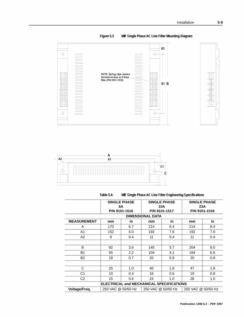
Installation 5-9
Figure 5.3 MIF Single Phase AC Line Filter Mounting Diagram
Table 5.4: MIF Single Phase AC Line Filter Engineering Specifications
SINGLE PHASE6A
P/N 9101-1516
SINGLE PHASE10A
P/N 9101-1517
SINGLE PHASE23A
P/N 9101-1518DIMENSIONAL DATA
MEASUREMENT mm in mm in mm inA 170 6.7 214 8.4 214 8.4
A1 152 6.0 192 7.6 192 7.6A2 9 0.4 11 0.4 11 0.4
B 92 3.6 145 5.7 204 8.0B1 55 2.2 104 4.1 164 6.6
B2 18 0.7 20 0.8 20 0.8
C 25 1.0 40 1.6 47 1.8
C1 10 0.4 16 0.6 19 0.8C2 15 0.6 24 1.0 28 1.0
ELECTRICAL and MECHANICAL SPECIFICATIONSVoltage/Freq. 250 VAC @ 50/50 Hz 250 VAC @ 50/50 Hz 250 VAC @ 50/50 Hz
Publication 1398-5.2 – PDF 1997
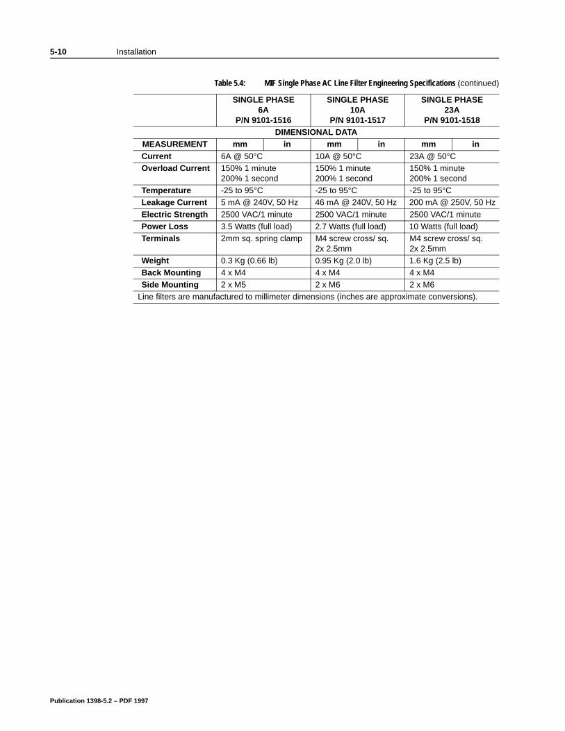
5-10 Installation
Current 6A @ 50°C 10A @ 50°C 23A @ 50°COverload Current 150% 1 minute
200% 1 second150% 1 minute200% 1 second
150% 1 minute200% 1 second
Temperature -25 to 95°C -25 to 95°C -25 to 95°CLeakage Current 5 mA @ 240V, 50 Hz 46 mA @ 240V, 50 Hz 200 mA @ 250V, 50 Hz
Electric Strength 2500 VAC/1 minute 2500 VAC/1 minute 2500 VAC/1 minutePower Loss 3.5 Watts (full load) 2.7 Watts (full load) 10 Watts (full load)Terminals 2mm sq. spring clamp M4 screw cross/ sq.
2x 2.5mmM4 screw cross/ sq. 2x 2.5mm
Weight 0.3 Kg (0.66 lb) 0.95 Kg (2.0 lb) 1.6 Kg (2.5 lb)
Back Mounting 4 x M4 4 x M4 4 x M4Side Mounting 2 x M5 2 x M6 2 x M6
Line filters are manufactured to millimeter dimensions (inches are approximate conversions).
Table 5.4: MIF Single Phase AC Line Filter Engineering Specifications (continued)
SINGLE PHASE6A
P/N 9101-1516
SINGLE PHASE10A
P/N 9101-1517
SINGLE PHASE23A
P/N 9101-1518DIMENSIONAL DATA
MEASUREMENT mm in mm in mm in
Publication 1398-5.2 – PDF 1997
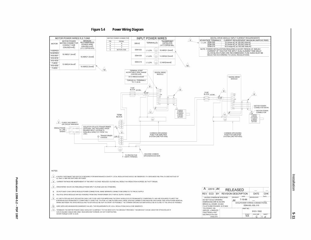
Installation5-11
Publication 1398-5.2 – P
DF
1997
Figure 5.4 Power Wiring Diagram

5-12 Installation
Publication 1398-5.2 – PDF 1997
Chapter 6
and
.
st
ow
Interfaces Chapter 6
This chapter provides information about:
Interface signals available on the ULTRA 100 Series drive
• J1 - The Controller interface for commanding and reportingmotion
• J2 - The Encoder interface for reporting movement by the motor
• J5 - The Serial interface for communicating with the drive.
Commonly encountered interface cabling methods
Optional signal extension kits and standard cables.
J1 – Controller J1 is a 50 pin female mini-D connector (AMP 2-178238-7) for connecting a host computer or controller to the drive. Contact between the connector’s shell and the grounded chassis provides shield termination. This section lists the connector pin-outs and providessignal specifications.
Cables are available in various lengths for connecting between J1a suitable controller. The appendix “Options and Accessories” on page A-1 lists the cables. “J1 Terminal Strip/Breakout Board” on page 6-24 details the optional signal extension kit that is available“Interface Cable Examples” beginning on page 6-21 depict variousinterface cable types commonly encountered in applications.
Digital I/O Power
The drive requires an external 12 to 24VDC power source for the inputs and outputs.
External I/O Power
The external I/O power supply must be capable of supplying at lea250 mA.
The pin-outs are:
The external I/O COM must be grounded to meet the European LVoltage Directive (LVD).
I/O PWR (12 to 24 Volts) J1-5 J1-26
I/O COM J1-6 J1-13
Publication 1398-5.2 – PDF 1997
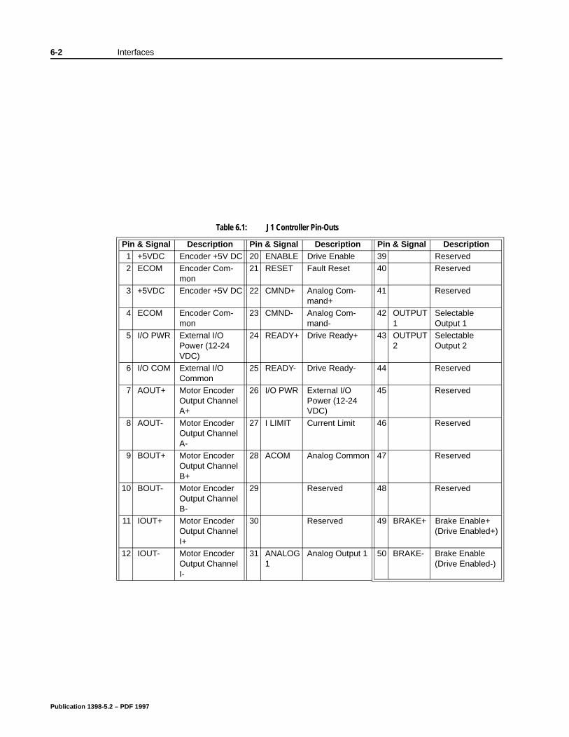
6-2 Interfaces
Table 6.1: J1 Controller Pin-Outs
Pin & Signal Description Pin & Signal Description Pin & Signal Description1 +5VDC Encoder +5V DC 20 ENABLE Drive Enable 39 Reserved2 ECOM Encoder Com-
mon21 RESET Fault Reset 40 Reserved
3 +5VDC Encoder +5V DC 22 CMND+ Analog Com-mand+
41 Reserved
4 ECOM Encoder Com-mon
23 CMND- Analog Com-mand-
42 OUTPUT1
Selectable Output 1
5 I/O PWR External I/O Power (12-24 VDC)
24 READY+ Drive Ready+ 43 OUTPUT2
Selectable Output 2
6 I/O COM External I/O Common
25 READY- Drive Ready- 44 Reserved
7 AOUT+ Motor Encoder Output Channel A+
26 I/O PWR External I/O Power (12-24 VDC)
45 Reserved
8 AOUT- Motor Encoder Output Channel A-
27 I LIMIT Current Limit 46 Reserved
9 BOUT+ Motor Encoder Output Channel B+
28 ACOM Analog Common 47 Reserved
10 BOUT- Motor Encoder Output Channel B-
29 Reserved 48 Reserved
11 IOUT+ Motor Encoder Output Channel I+
30 Reserved 49 BRAKE+ Brake Enable+ (Drive Enabled+)
12 IOUT- Motor Encoder Output Channel I-
31 ANALOG1
Analog Output 1 50 BRAKE- Brake Enable (Drive Enabled-)
Publication 1398-5.2 – PDF 1997
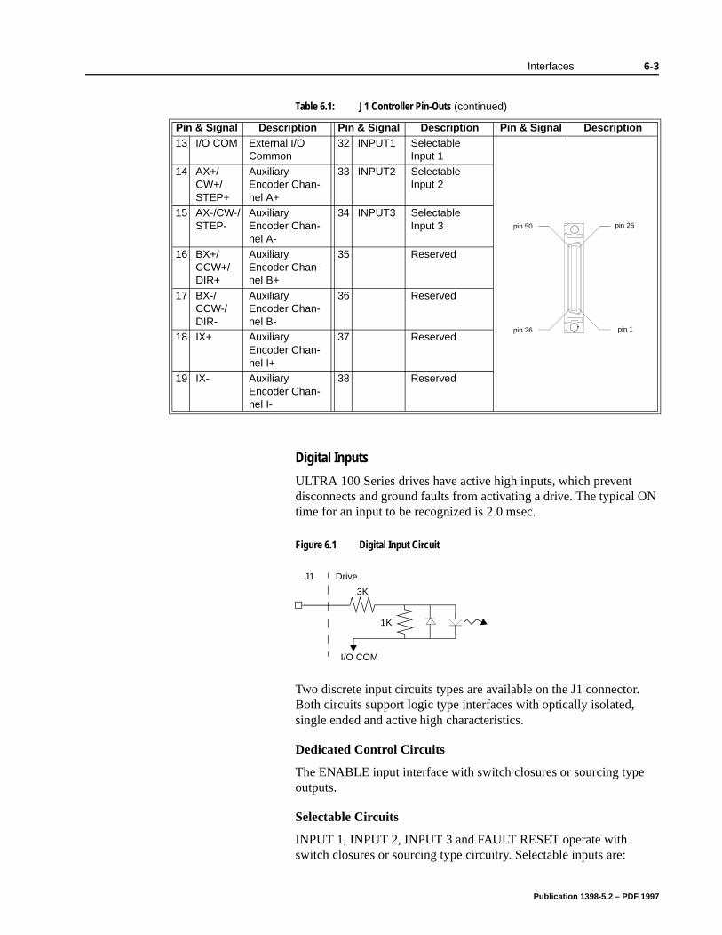
Interfaces 6-3
Digital Inputs
ULTRA 100 Series drives have active high inputs, which prevent disconnects and ground faults from activating a drive. The typical ON time for an input to be recognized is 2.0 msec.
Two discrete input circuits types are available on the J1 connector. Both circuits support logic type interfaces with optically isolated, single ended and active high characteristics.
Dedicated Control Circuits
The ENABLE input interface with switch closures or sourcing type outputs.
Selectable Circuits
INPUT 1, INPUT 2, INPUT 3 and FAULT RESET operate with switch closures or sourcing type circuitry. Selectable inputs are:
13 I/O COM External I/O Common
32 INPUT1 Selectable Input 1
14 AX+/CW+/STEP+
Auxiliary Encoder Chan-nel A+
33 INPUT2 Selectable Input 2
15 AX-/CW-/STEP-
Auxiliary Encoder Chan-nel A-
34 INPUT3 Selectable Input 3
16 BX+/CCW+/DIR+
Auxiliary Encoder Chan-nel B+
35 Reserved
17 BX-/CCW-/DIR-
Auxiliary Encoder Chan-nel B-
36 Reserved
18 IX+ Auxiliary Encoder Chan-nel I+
37 Reserved
19 IX- Auxiliary Encoder Chan-nel I-
38 Reserved
Table 6.1: J1 Controller Pin-Outs (continued)
Pin & Signal Description Pin & Signal Description Pin & Signal Description
pin 25
pin 26
pin 50
pin 1
Figure 6.1 Digital Input Circuit
DriveJ1
3K
1K
I/O COM
Publication 1398-5.2 – PDF 1997
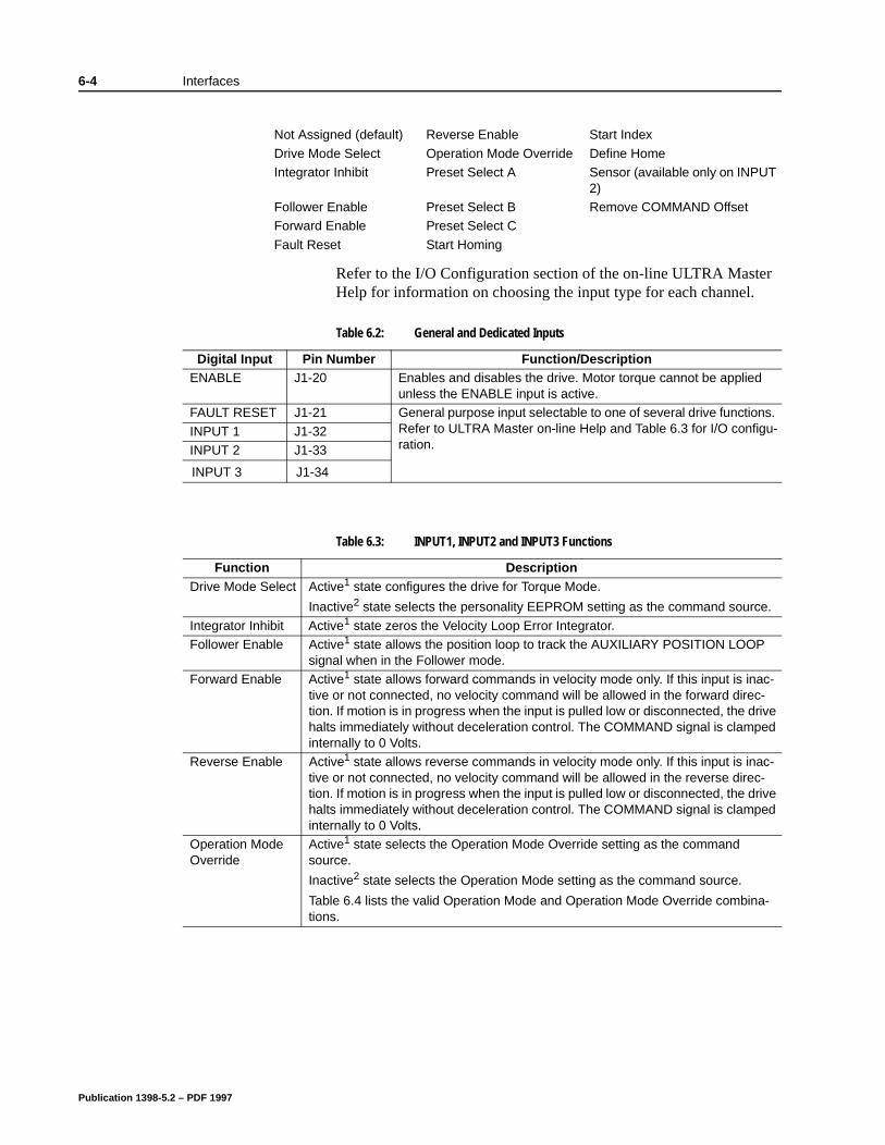
6-4 Interfaces
Refer to the I/O Configuration section of the on-line ULTRA Master Help for information on choosing the input type for each channel.
Not Assigned (default) Reverse Enable Start Index
Drive Mode Select Operation Mode Override Define HomeIntegrator Inhibit Preset Select A Sensor (available only on INPUT
2)Follower Enable Preset Select B Remove COMMAND OffsetForward Enable Preset Select C
Fault Reset Start Homing
Table 6.2: General and Dedicated Inputs
Digital Input Pin Number Function/DescriptionENABLE J1-20 Enables and disables the drive. Motor torque cannot be applied
unless the ENABLE input is active.FAULT RESET J1-21 General purpose input selectable to one of several drive functions.
Refer to ULTRA Master on-line Help and Table 6.3 for I/O configu-ration.
INPUT 1 J1-32INPUT 2 J1-33
INPUT 3 J1-34
Table 6.3: INPUT1, INPUT2 and INPUT3 Functions
Function DescriptionDrive Mode Select Active1 state configures the drive for Torque Mode.
Inactive2 state selects the personality EEPROM setting as the command source.
Integrator Inhibit Active1 state zeros the Velocity Loop Error Integrator. Follower Enable Active1 state allows the position loop to track the AUXILIARY POSITION LOOP
signal when in the Follower mode. Forward Enable Active1 state allows forward commands in velocity mode only. If this input is inac-
tive or not connected, no velocity command will be allowed in the forward direc-tion. If motion is in progress when the input is pulled low or disconnected, the drive halts immediately without deceleration control. The COMMAND signal is clamped internally to 0 Volts.
Reverse Enable Active1 state allows reverse commands in velocity mode only. If this input is inac-tive or not connected, no velocity command will be allowed in the reverse direc-tion. If motion is in progress when the input is pulled low or disconnected, the drive halts immediately without deceleration control. The COMMAND signal is clamped internally to 0 Volts.
Operation Mode Override
Active1 state selects the Operation Mode Override setting as the command source.
Inactive2 state selects the Operation Mode setting as the command source.
Table 6.4 lists the valid Operation Mode and Operation Mode Override combina-tions.
Publication 1398-5.2 – PDF 1997
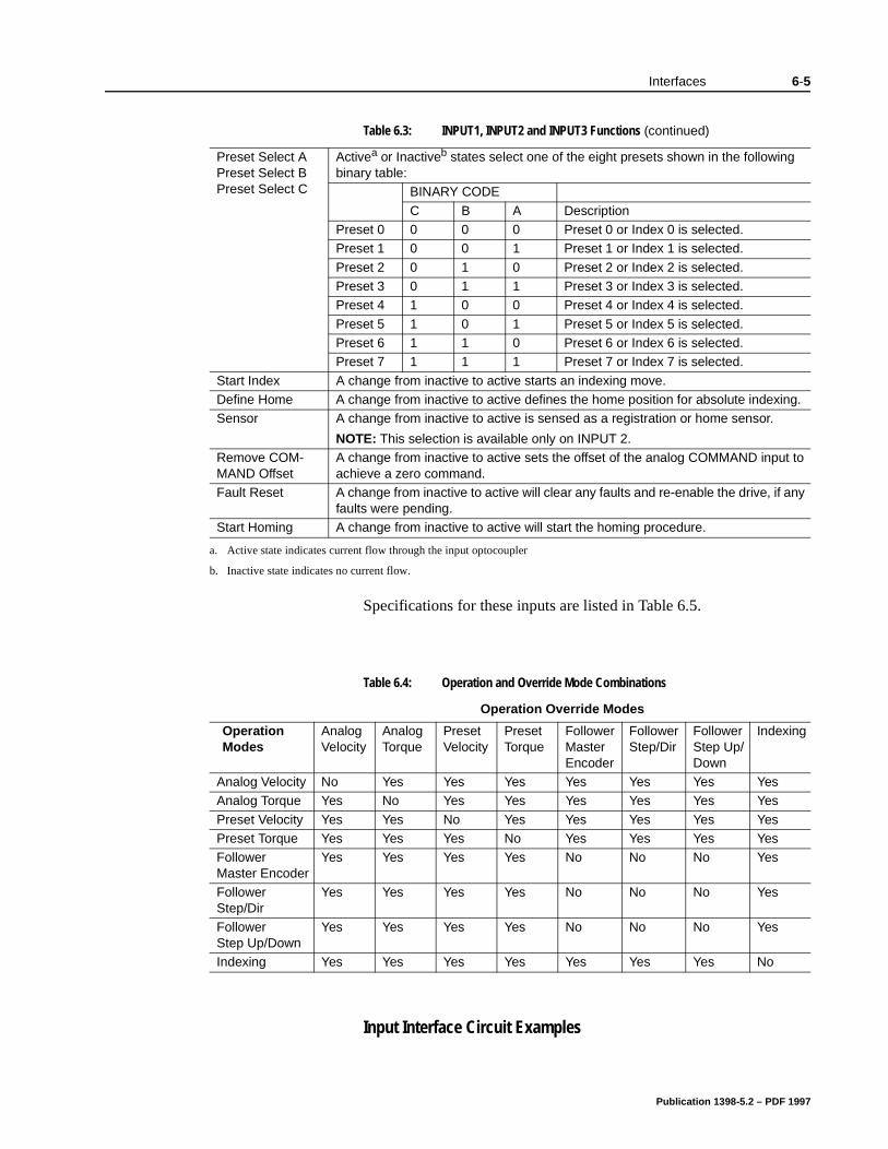
Interfaces 6-5
Specifications for these inputs are listed in Table 6.5.
Input Interface Circuit Examples
Preset Select APreset Select BPreset Select C
Activea or Inactiveb states select one of the eight presets shown in the following binary table:
BINARY CODE
C B A DescriptionPreset 0 0 0 0 Preset 0 or Index 0 is selected. Preset 1 0 0 1 Preset 1 or Index 1 is selected.
Preset 2 0 1 0 Preset 2 or Index 2 is selected. Preset 3 0 1 1 Preset 3 or Index 3 is selected. Preset 4 1 0 0 Preset 4 or Index 4 is selected.
Preset 5 1 0 1 Preset 5 or Index 5 is selected. Preset 6 1 1 0 Preset 6 or Index 6 is selected. Preset 7 1 1 1 Preset 7 or Index 7 is selected.
Start Index A change from inactive to active starts an indexing move. Define Home A change from inactive to active defines the home position for absolute indexing. Sensor A change from inactive to active is sensed as a registration or home sensor.
NOTE: This selection is available only on INPUT 2.Remove COM-MAND Offset
A change from inactive to active sets the offset of the analog COMMAND input to achieve a zero command.
Fault Reset A change from inactive to active will clear any faults and re-enable the drive, if any faults were pending.
Start Homing A change from inactive to active will start the homing procedure.
a. Active state indicates current flow through the input optocoupler
b. Inactive state indicates no current flow.
Table 6.3: INPUT1, INPUT2 and INPUT3 Functions (continued)
Table 6.4: Operation and Override Mode Combinations
Operation Override Modes
Operation Modes
Analog Velocity
Analog Torque
Preset Velocity
Preset Torque
Follower Master Encoder
Follower Step/Dir
Follower Step Up/Down
Indexing
Analog Velocity No Yes Yes Yes Yes Yes Yes YesAnalog Torque Yes No Yes Yes Yes Yes Yes Yes
Preset Velocity Yes Yes No Yes Yes Yes Yes YesPreset Torque Yes Yes Yes No Yes Yes Yes YesFollower Master Encoder
Yes Yes Yes Yes No No No Yes
Follower Step/Dir
Yes Yes Yes Yes No No No Yes
Follower Step Up/Down
Yes Yes Yes Yes No No No Yes
Indexing Yes Yes Yes Yes Yes Yes Yes No
Publication 1398-5.2 – PDF 1997
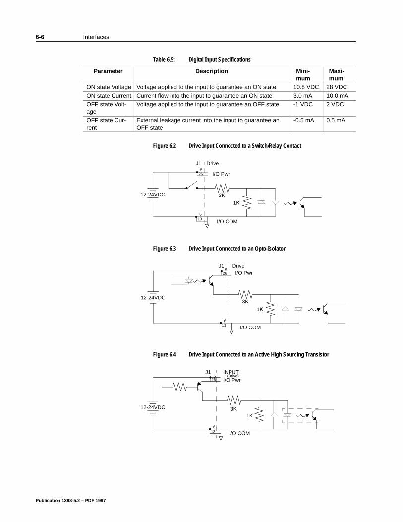
6-6 Interfaces
Table 6.5: Digital Input Specifications
Parameter Description Mini-mum
Maxi-mum
ON state Voltage Voltage applied to the input to guarantee an ON state 10.8 VDC 28 VDC
ON state Current Current flow into the input to guarantee an ON state 3.0 mA 10.0 mAOFF state Volt-age
Voltage applied to the input to guarantee an OFF state -1 VDC 2 VDC
OFF state Cur-rent
External leakage current into the input to guarantee an OFF state
-0.5 mA 0.5 mA
Figure 6.2 Drive Input Connected to a Switch/Relay Contact
Figure 6.3 Drive Input Connected to an Opto-Isolator
Figure 6.4 Drive Input Connected to an Active High Sourcing Transistor
1K
3K
DriveJ1
I/O Pwr265
I/O COM
12-24VDC
136
1K
3K
I/O Pwr265
DriveJ1
I/O COM
12-24VDC
136
265
INPUTJ1
I/O COM
I/O Pwr
3K1K
(Drive)
12-24VDC
136
Publication 1398-5.2 – PDF 1997
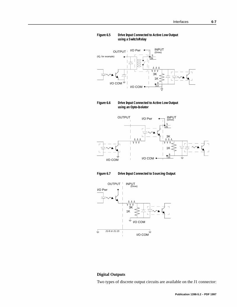
Interfaces 6-7
Digital Outputs
Two types of discrete output circuits are available on the J1 connector:
Figure 6.5 Drive Input Connected to Active Low Output using a Switch/Relay
Figure 6.6 Drive Input Connected to Active Low Output using an Opto-Isolator
Figure 6.7 Drive Input Connected to Sourcing Output
(Drive)OUTPUT
(IQ, for example)
INPUT
3K
1K
I/O COM 136
265
I/O Pwr
I/O COM
(Drive)INPUTOUTPUT
3K
1K
I/O COM I/O COM 136
265
I/O Pwr
I/O COM
I/O Pwr
1K3K
INPUT(Drive)
OUTPUT
I/O COMJ1-6 or J1-13
Publication 1398-5.2 – PDF 1997
6-8 Interfaces
ay efer
Dedicated relay outputs
Selectable transistor based outputs
Both types support 12-24 VDC logic interfaces:
Dedicated Relay Outputs
BRAKE/DRIVE ENABLED and DRIVE READY. Each output is a normally open relay. The relays are rated for 1 Amp at 30 VDC.
Note: The Brake contacts may be used to control 24VDC brakes on Allen-Bradley motors with a 4” frame or smaller. A user provided relmay be driven by these outputs if higher power levels are required. Rto Figure 6.10 for examples.
Publication 1398-5.2 – PDF 1997
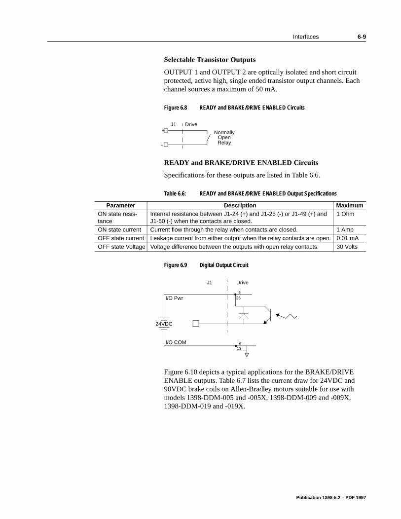
Interfaces 6-9
Selectable Transistor Outputs
OUTPUT 1 and OUTPUT 2 are optically isolated and short circuit protected, active high, single ended transistor output channels. Each channel sources a maximum of 50 mA.
READY and BRAKE/DRIVE ENABLED Circuits
Specifications for these outputs are listed in Table 6.6.
Figure 6.10 depicts a typical applications for the BRAKE/DRIVE ENABLE outputs. Table 6.7 lists the current draw for 24VDC and 90VDC brake coils on Allen-Bradley motors suitable for use with models 1398-DDM-005 and -005X, 1398-DDM-009 and -009X, 1398-DDM-019 and -019X.
Figure 6.8 READY and BRAKE/DRIVE ENABLED Circuits
J1 Drive+
-
NormallyOpenRelay
Table 6.6: READY and BRAKE/DRIVE ENABLED Output Specifications
Parameter Description MaximumON state resis-tance
Internal resistance between J1-24 (+) and J1-25 (-) or J1-49 (+) and J1-50 (-) when the contacts are closed.
1 Ohm
ON state current Current flow through the relay when contacts are closed. 1 AmpOFF state current Leakage current from either output when the relay contacts are open. 0.01 mA
OFF state Voltage Voltage difference between the outputs with open relay contacts. 30 Volts
Figure 6.9 Digital Output Circuit
265
24VDC
136I/O COM
I/O Pwr
J1 Drive
Publication 1398-5.2 – PDF 1997
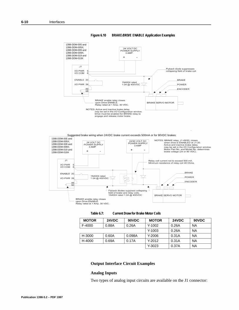
6-10 Interfaces
Output Interface Circuit Examples
Analog Inputs
Two types of analog input circuits are available on the J1 connector:
Figure 6.10 BRAKE/DRIVE ENABLE Application Examples
Table 6.7: Current Draw for Brake Motor Coils
MOTOR 24VDC 90VDC MOTOR 24VDC 90VDCF-4000 0.88A 0.26A Y-1002 0.26A NA
Y-1003 0.26A NAH-3000 0.60A 0.098A Y-2006 0.31A NAH-4000 0.69A 0.17A Y-2012 0.31A NA
Y-3023 0.37A NA
Suggested brake wiring when 24VDC brake current exceeds 500mA or for 90VDC brakes: 1398-DDM-005 and 1398-DDM-005X; 1398-DDM-009 and 1398-DDM-009X; 1398-DDM-019 and 1398-DDM-019X
1398-DDM-005 and 1398-DDM-005X; 1398-DDM-009 and 1398-DDM-009X; 1398-DDM-019 and 1398-DDM-019X
Publication 1398-5.2 – PDF 1997
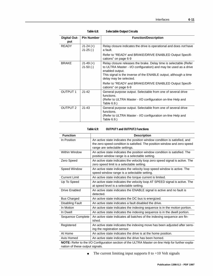
Interfaces 6-11
The current limiting input supports 0 to +10 Volt signals
Table 6.8: Selectable Output Circuits
Digital Out-put
Pin Number Function/Description
READY J1-24 (+) J1-25 (-)
Relay closure indicates the drive is operational and does not have a fault.
Refer to “READY and BRAKE/DRIVE ENABLED Output Specifi-cations” on page 6-9
BRAKE J1-49 (+) J1-50 (-)
Relay closure releases the brake. Delay time is selectable (Refer to ULTRA Master - I/O configuration) and may be used as a drive enabled output. This signal is the inverse of the ENABLE output, although a time delay may be selected.
Refer to “READY and BRAKE/DRIVE ENABLED Output Specifi-cations” on page 6-9
OUTPUT 1 J1-42 General purpose output. Selectable from one of several drive functions. (Refer to ULTRA Master - I/O configuration on-line Help and Table 6.9.)
OUTPUT 2 J1-43 General purpose output. Selectable from one of several drive functions. (Refer to ULTRA Master - I/O configuration on-line Help and Table 6.9.)
Table 6.9: OUTPUT1 and OUTPUT2 Functions
Function DescriptionIn Position An active state indicates the position window condition is satisfied, and
the zero speed condition is satisfied. The position window and zero speed range are selectable settings.
Within Window An active state indicates the position window condition is satisfied. The position window range is a selectable setting.
Zero Speed An active state indicates the velocity loop zero speed signal is active. The zero speed limit is a selectable setting.
Speed Window An active state indicates the velocity loop speed window is active. The speed window range is a selectable setting.
Current Limit An active state indicates the torque current is limited. Up To Speed An active state indicates the velocity loop AT SPEED signal is active. The
at speed level is a selectable setting. Drive Enabled An active state indicates the ENABLE signal is active and no fault is
detected. Bus Charged An active state indicates the DC bus is energized. Disabling Fault An active state indicates a fault disabled the drive.
In Motion An active state indicates the indexing sequence is in the motion portion.In Dwell An active state indicates the indexing sequence is in the dwell portion. Sequence Complete An active state indicates all batches of the indexing sequence are fin-
ished. Registered An active state indicates the indexing move has been adjusted after sens-
ing the registration sensor. At Home An active state indicates the drive is at the home position.
Axis Homed An active state indicates the drive has been homed. NOTE: Refer to the I/O Configuration section of the ULTRA Master on-line Help for further expla-nation of these output signals.
Publication 1398-5.2 – PDF 1997
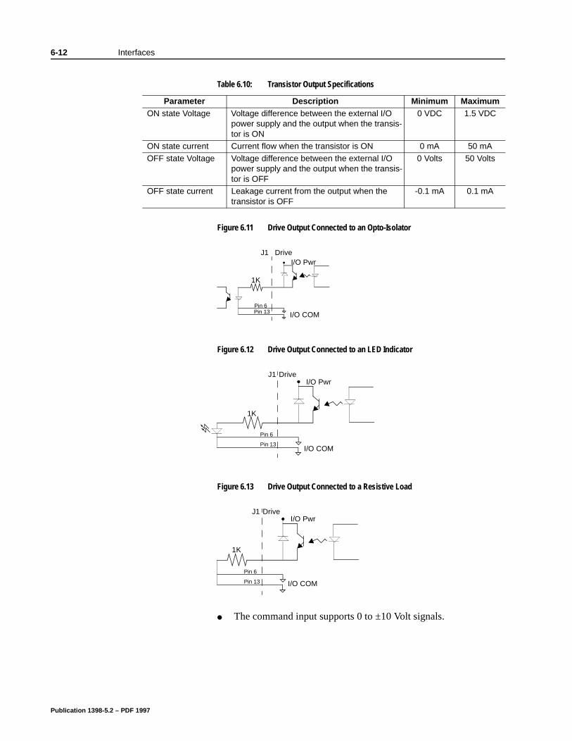
6-12 Interfaces
The command input supports 0 to ±10 Volt signals.
Table 6.10: Transistor Output Specifications
Parameter Description Minimum MaximumON state Voltage Voltage difference between the external I/O
power supply and the output when the transis-tor is ON
0 VDC 1.5 VDC
ON state current Current flow when the transistor is ON 0 mA 50 mA
OFF state Voltage Voltage difference between the external I/O power supply and the output when the transis-tor is OFF
0 Volts 50 Volts
OFF state current Leakage current from the output when the transistor is OFF
-0.1 mA 0.1 mA
Figure 6.11 Drive Output Connected to an Opto-Isolator
Figure 6.12 Drive Output Connected to an LED Indicator
Figure 6.13 Drive Output Connected to a Resistive Load
DriveJ1I/O Pwr
Pin 13Pin 6
I/O COM
1K
1K
I/O Pwr
Pin 13
Pin 6
DriveJ1
I/O COM
Pin 13
Pin 6
DriveJ1
I/O COM
I/O Pwr
1K
Publication 1398-5.2 – PDF 1997
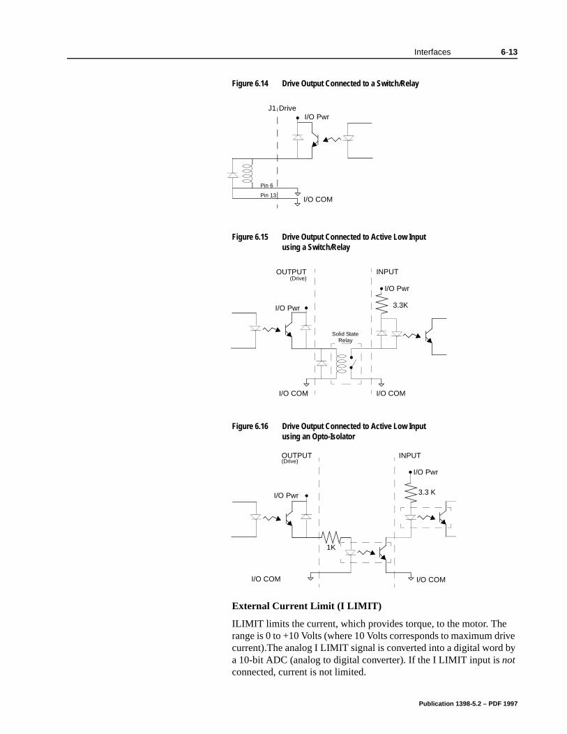
Interfaces 6-13
External Current Limit (I LIMIT)
ILIMIT limits the current, which provides torque, to the motor. The range is 0 to +10 Volts (where 10 Volts corresponds to maximum drive current).The analog I LIMIT signal is converted into a digital word by a 10-bit ADC (analog to digital converter). If the I LIMIT input is not connected, current is not limited.
Figure 6.14 Drive Output Connected to a Switch/Relay
Figure 6.15 Drive Output Connected to Active Low Input using a Switch/Relay
Figure 6.16 Drive Output Connected to Active Low Input using an Opto-Isolator
Pin 13
Pin 6
DriveJ1
I/O COM
I/O Pwr
Solid StateRelay
(Drive)
I/O COM I/O COM
3.3K
I/O Pwr
I/O Pwr
INPUTOUTPUT
I/O COM
I/O Pwr
1K
I/O COM
I/O Pwr
3.3 K
INPUTOUTPUT(Drive)
Publication 1398-5.2 – PDF 1997
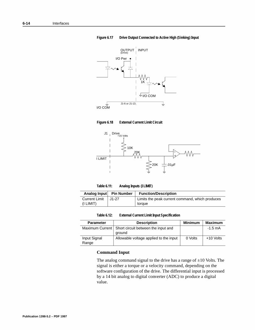
6-14 Interfaces
The ed
Command Input
The analog command signal to the drive has a range of ±10 Volts. signal is either a torque or a velocity command, depending on thesoftware configuration of the drive. The differential input is processby a 14 bit analog to digital converter (ADC) to produce a digital value.
Figure 6.17 Drive Output Connected to Active High (Sinking) Input
Figure 6.18 External Current Limit Circuit
Table 6.11: Analog Inputs (I LIMIT)
Analog Input Pin Number Function/DescriptionCurrent Limit (I LIMIT)
J1-27 Limits the peak current command, which produces torque
Table 6.12: External Current Limit Input Specification
Parameter Description Minimum MaximumMaximum Current Short circuit between the input and
ground -1.5 mA
Input Signal Range
Allowable voltage applied to the input 0 Volts +10 Volts
I/O COM
I/O Pwr
INPUTOUTPUT(Drive)
I/O COMJ1-6 or J1-13
1K
DriveJ1+15 Volts
10K
20K .01µF
20K -+
I LIMIT
Publication 1398-5.2 – PDF 1997
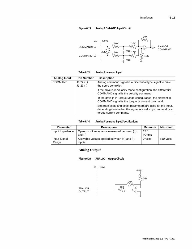
Interfaces 6-15
Analog Output
Figure 6.19 Analog COMMAND Input Circuit
Table 6.13: Analog Command Input
Analog Input Pin Number DescriptionCOMMAND J1-22 (+)
J1-23 (-)Analog command signal is a differential type signal to drive the servo controller.
If the drive is in Velocity Mode configuration, the differential COMMAND signal is the velocity command.
If the drive is in Torque Mode configuration, the differential COMMAND signal is the torque or current command.
Separate scale and offset parameters are used for the input, depending on whether the signal is a velocity command or a torque current command.
Table 6.14: Analog Command Input Specifications
Parameter Description Minimum MaximumInput Impedance Open circuit impedance measured between (+)
and (-) 13.3 kOhms
Input Signal Range
Allowable voltage applied between (+) and (-) inputs
0 Volts ±10 Volts
DriveJ1
COMMAND+
COMMAND-
10K
20K
10K
10K 10K
ANALOG+-
COMMAND
10K
10K
.01uF
.01uF
Figure 6.20 ANALOG 1 Output Circuit
DriveJ1-5 Volts
10K
100 -+
20K
ANALOGOUTPUT
Publication 1398-5.2 – PDF 1997
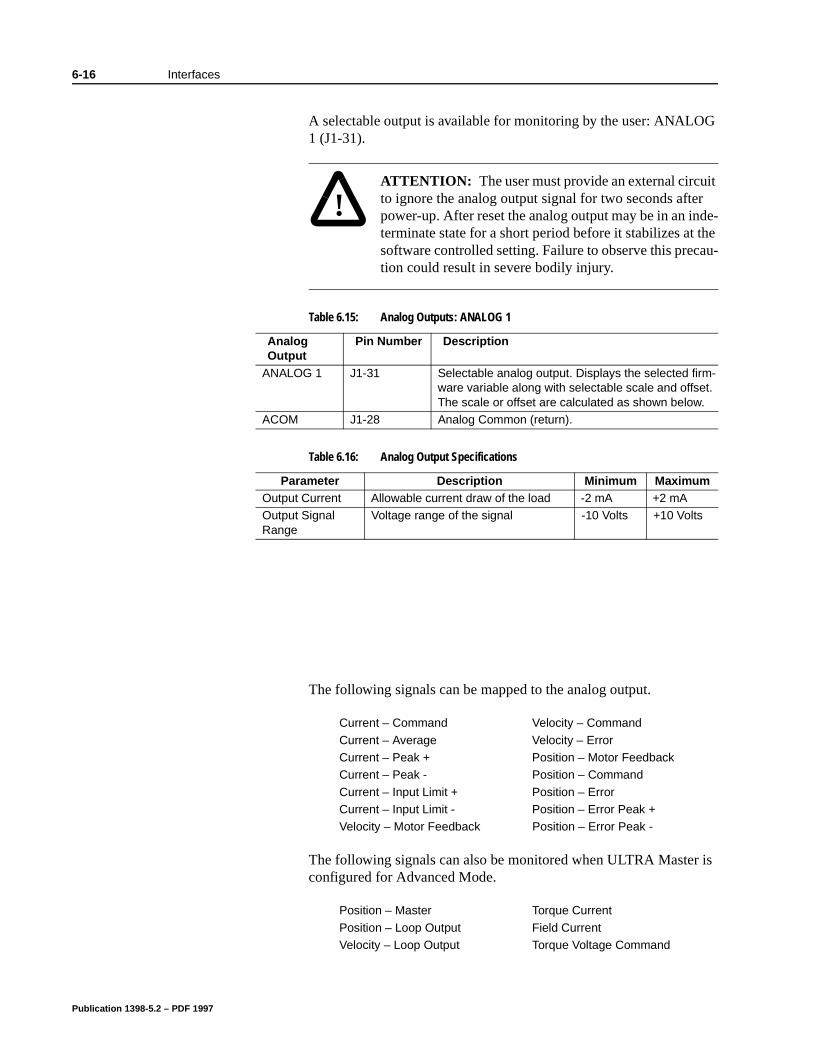
6-16 Interfaces
A selectable output is available for monitoring by the user: ANALOG 1 (J1-31).
The following signals can be mapped to the analog output.
The following signals can also be monitored when ULTRA Master is configured for Advanced Mode.
!
Intro
ATTENTION: The user must provide an external circuit to ignore the analog output signal for two seconds after power-up. After reset the analog output may be in an inde-terminate state for a short period before it stabilizes at the software controlled setting. Failure to observe this precau-tion could result in severe bodily injury.
Table 6.15: Analog Outputs: ANALOG 1
Analog Output
Pin Number Description
ANALOG 1 J1-31 Selectable analog output. Displays the selected firm-ware variable along with selectable scale and offset. The scale or offset are calculated as shown below.
ACOM J1-28 Analog Common (return).
Table 6.16: Analog Output Specifications
Parameter Description Minimum MaximumOutput Current Allowable current draw of the load -2 mA +2 mAOutput Signal Range
Voltage range of the signal -10 Volts +10 Volts
Current – Command Velocity – Command
Current – Average Velocity – ErrorCurrent – Peak + Position – Motor FeedbackCurrent – Peak - Position – Command
Current – Input Limit + Position – ErrorCurrent – Input Limit - Position – Error Peak +Velocity – Motor Feedback Position – Error Peak -
Position – Master Torque Current
Position – Loop Output Field CurrentVelocity – Loop Output Torque Voltage Command
Publication 1398-5.2 – PDF 1997
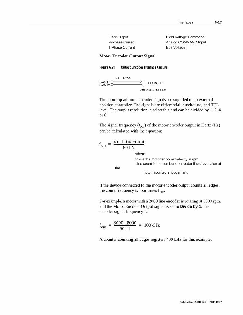
Interfaces 6-17
Motor Encoder Output Signal
The motor quadrature encoder signals are supplied to an external position controller. The signals are differential, quadrature, and TTL level. The output resolution is selectable and can be divided by 1, 2, 4 or 8.
The signal frequency (fout) of the motor encoder output in Hertz (Hz) can be calculated with the equation:
If the device connected to the motor encoder output counts all edges, the count frequency is four times fout.
For example, a motor with a 2000 line encoder is rotating at 3000 rpm, and the Motor Encoder Output signal is set to Divide by 1, the encoder signal frequency is:
A counter counting all edges registers 400 kHz for this example.
Filter Output Field Voltage Command
R-Phase Current Analog COMMAND InputT-Phase Current Bus Voltage
Figure 6.21 Output Encoder Interface Circuits
AOUT-AOUT+ AMOUT
AM26C31 or AM26LS31
DriveJ1
foutVm linecount⋅
60 N⋅---------------------------------------=
where:
Vm is the motor encoder velocity in rpmLine count is the number of encoder lines/revolution of
the motor mounted encoder, and
fout3000 2000⋅
60 1⋅---------------------------- 100kHz= =
Publication 1398-5.2 – PDF 1997
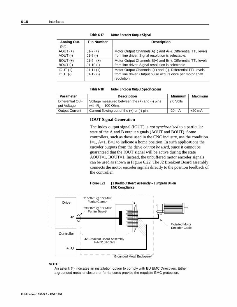
6-18 Interfaces
IOUT Signal Generation
The Index output signal (IOUT) is not synchronized to a particular state of the A and B output signals (AOUT and BOUT). Some controllers, such as those used in the CNC industry, use the condition I=1, A=1, B=1 to indicate a home position. In such applications the encoder outputs from the drive cannot be used, since it cannot be guaranteed that the IOUT signal will be active during the state AOUT=1, BOUT=1. Instead, the unbuffered motor encoder signals can be used as shown in Figure 6.22. The J2 Breakout Board assembly connects the motor encoder signals directly to the position feedback of the controller.
Table 6.17: Motor Encoder Output Signal
Analog Out-put
Pin Number Description
AOUT (+) AOUT (-)
J1-7 (+)J1-8 (-)
Motor Output Channels A(+) and A(-). Differential TTL levels from line driver. Signal resolution is selectable.
BOUT (+) BOUT (-)
J1-9 (+)J1-10 (-)
Motor Output Channels B(+) and B(-). Differential TTL levels from line driver. Signal resolution is selectable.
IOUT (+) IOUT (-)
J1-11 (+)J1-12 (-)
Motor Output Channels I(+) and I(-). Differential TTL levels from line driver. Output pulse occurs once per motor shaft revolution.
Table 6.18: Motor Encoder Output Specifications
Parameter Description Minimum MaximumDifferential Out-put Voltage
Voltage measured between the (+) and (-) pins with RL = 100 Ohm.
2.0 Volts
Output Current Current flowing out of the (+) or (-) pin. -20 mA +20 mA
Figure 6.22 J2 Breakout Board Assembly – European Union EMC Compliance
Drive
Controller
J2
A,B,I
J2 Breakout Board Assembly P/N 9101-1392
Pigtailed Motor Encoder Cable
Grounded Metal Enclosure*
230Ohm @ 100MHzFerrite Toroid*
215Ohm @ 100MHzFerrite Clamp*
NOTE:An asterik (*) indicates an installation option to comply with EU EMC Directives. Either a grounded metal enclosure or ferrite cores provide the requisite EMC protection.
Publication 1398-5.2 – PDF 1997

Interfaces 6-19
Note: If a controller connected to the drive requires the Index Output (IOUT) signal to be synchronized to a particular state of the A and B Outputs (AOUT and BOUT) the unbuffered encoder outputs from the motor must be used. (Required for use with A-B 1746, 1771, 4100 and 1354 motion controllers.)
Publication 1398-5.2 – PDF 1997
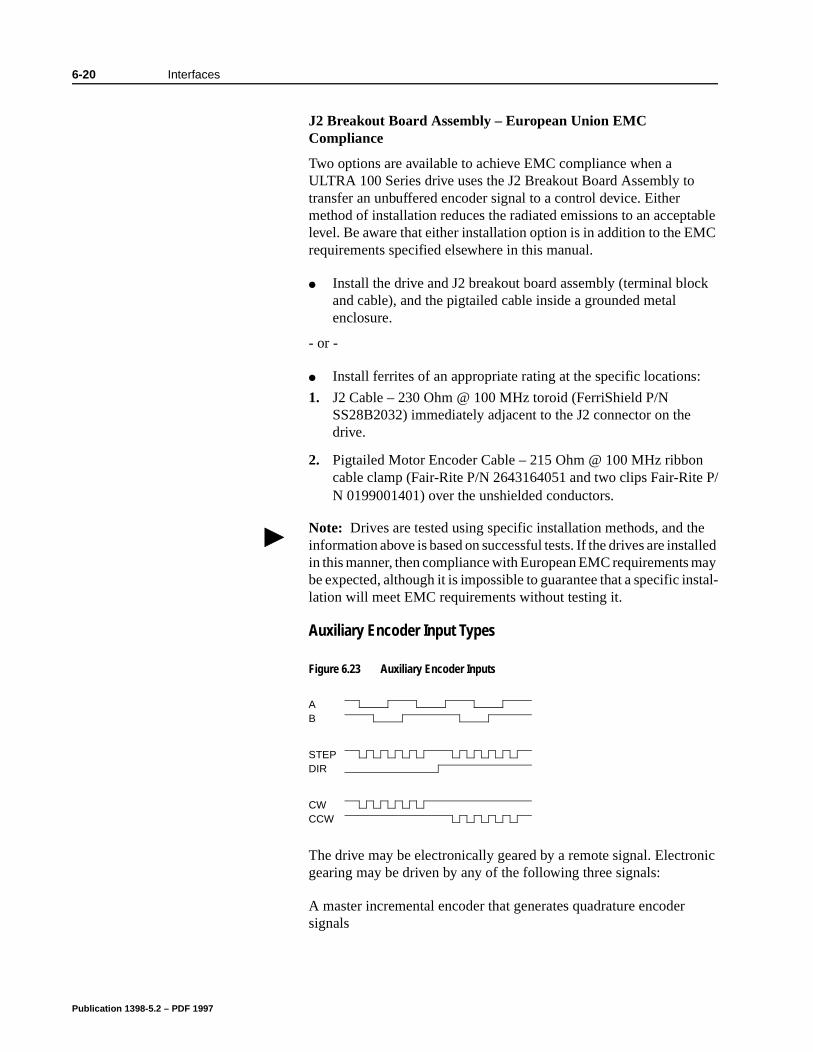
6-20 Interfaces
P/
nic
J2 Breakout Board Assembly – European Union EMC Compliance
Two options are available to achieve EMC compliance when a ULTRA 100 Series drive uses the J2 Breakout Board Assembly to transfer an unbuffered encoder signal to a control device. Either method of installation reduces the radiated emissions to an acceptable level. Be aware that either installation option is in addition to the EMC requirements specified elsewhere in this manual.
Install the drive and J2 breakout board assembly (terminal block and cable), and the pigtailed cable inside a grounded metal enclosure.
- or -
Install ferrites of an appropriate rating at the specific locations:
1. J2 Cable – 230 Ohm @ 100 MHz toroid (FerriShield P/N SS28B2032) immediately adjacent to the J2 connector on the drive.
2. Pigtailed Motor Encoder Cable – 215 Ohm @ 100 MHz ribboncable clamp (Fair-Rite P/N 2643164051 and two clips Fair-RiteN 0199001401) over the unshielded conductors.
Auxiliary Encoder Input Types
The drive may be electronically geared by a remote signal. Electrogearing may be driven by any of the following three signals:
A master incremental encoder that generates quadrature encodersignals
Note: Drives are tested using specific installation methods, and the information above is based on successful tests. If the drives are installed in this manner, then compliance with European EMC requirements may be expected, although it is impossible to guarantee that a specific instal-lation will meet EMC requirements without testing it.
Figure 6.23 Auxiliary Encoder Inputs
AB
STEPDIR
CWCCW
Publication 1398-5.2 – PDF 1997
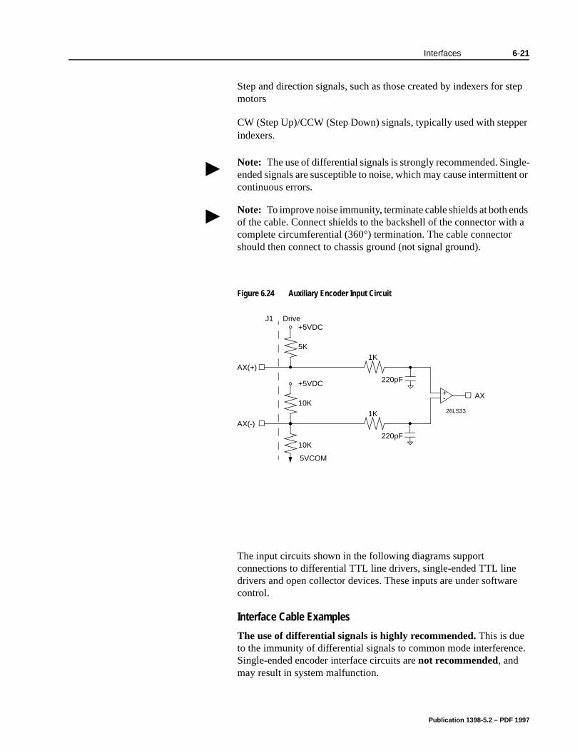
Interfaces 6-21
Step and direction signals, such as those created by indexers for step motors
CW (Step Up)/CCW (Step Down) signals, typically used with stepper indexers.
The input circuits shown in the following diagrams support connections to differential TTL line drivers, single-ended TTL line drivers and open collector devices. These inputs are under software control.
Interface Cable Examples
The use of differential signals is highly recommended. This is due to the immunity of differential signals to common mode interference. Single-ended encoder interface circuits are not recommended, and may result in system malfunction.
Note: The use of differential signals is strongly recommended. Single-ended signals are susceptible to noise, which may cause intermittent or continuous errors.
Note: To improve noise immunity, terminate cable shields at both ends of the cable. Connect shields to the backshell of the connector with a complete circumferential (360°) termination. The cable connector should then connect to chassis ground (not signal ground).
Figure 6.24 Auxiliary Encoder Input Circuit
-+
26LS33
AX(-)
1K
220pF
AX
220pF
AX(+)
1K
5K
+5VDC
10K
+5VDC
10K
5VCOM
DriveJ1
Publication 1398-5.2 – PDF 1997
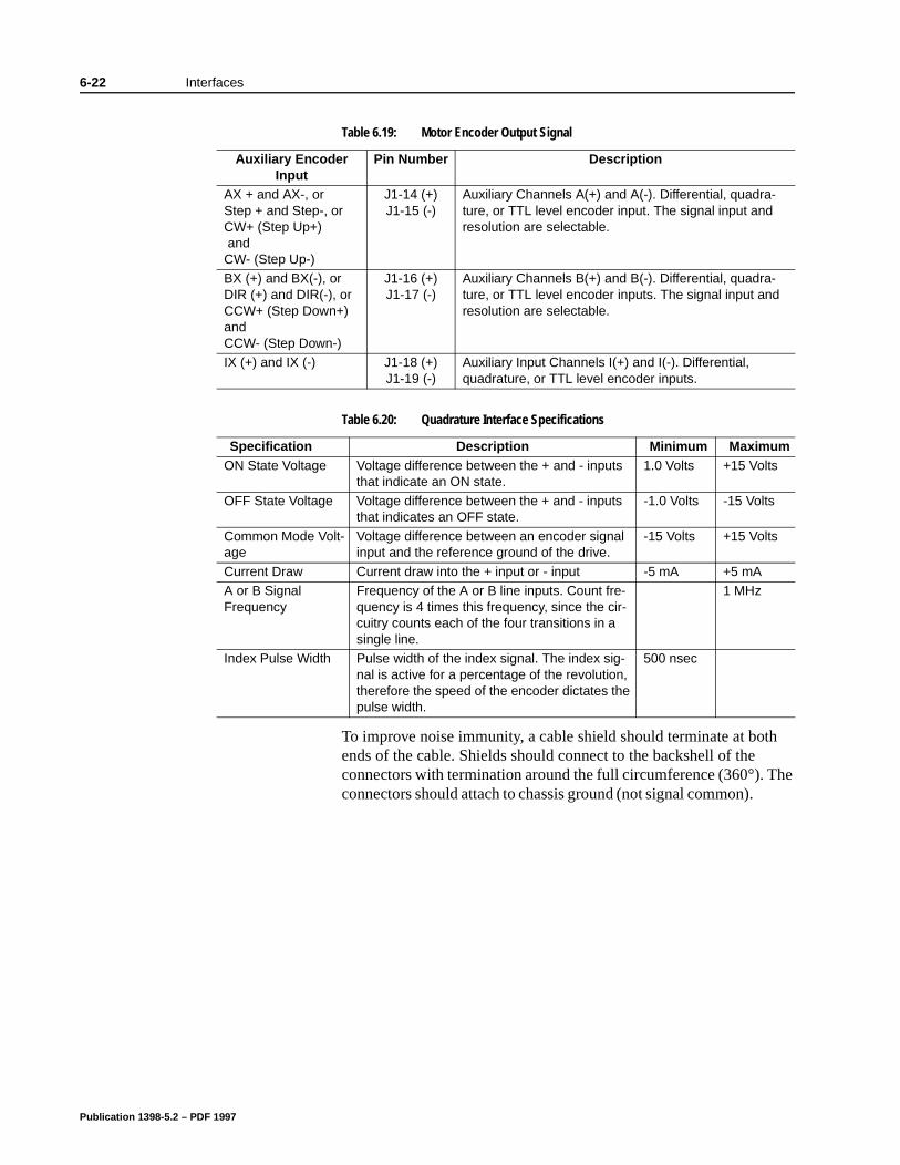
6-22 Interfaces
he
To improve noise immunity, a cable shield should terminate at both ends of the cable. Shields should connect to the backshell of the connectors with termination around the full circumference (360°). Tconnectors should attach to chassis ground (not signal common).
Table 6.19: Motor Encoder Output Signal
Auxiliary Encoder Input
Pin Number Description
AX + and AX-, or Step + and Step-, orCW+ (Step Up+) and CW- (Step Up-)
J1-14 (+)J1-15 (-)
Auxiliary Channels A(+) and A(-). Differential, quadra-ture, or TTL level encoder input. The signal input and resolution are selectable.
BX (+) and BX(-), orDIR (+) and DIR(-), orCCW+ (Step Down+) and CCW- (Step Down-)
J1-16 (+)J1-17 (-)
Auxiliary Channels B(+) and B(-). Differential, quadra-ture, or TTL level encoder inputs. The signal input and resolution are selectable.
IX (+) and IX (-) J1-18 (+)J1-19 (-)
Auxiliary Input Channels I(+) and I(-). Differential, quadrature, or TTL level encoder inputs.
Table 6.20: Quadrature Interface Specifications
Specification Description Minimum MaximumON State Voltage Voltage difference between the + and - inputs
that indicate an ON state.1.0 Volts +15 Volts
OFF State Voltage Voltage difference between the + and - inputs that indicates an OFF state.
-1.0 Volts -15 Volts
Common Mode Volt-age
Voltage difference between an encoder signal input and the reference ground of the drive.
-15 Volts +15 Volts
Current Draw Current draw into the + input or - input -5 mA +5 mAA or B Signal Frequency
Frequency of the A or B line inputs. Count fre-quency is 4 times this frequency, since the cir-cuitry counts each of the four transitions in a single line.
1 MHz
Index Pulse Width Pulse width of the index signal. The index sig-nal is active for a percentage of the revolution, therefore the speed of the encoder dictates the pulse width.
500 nsec
Publication 1398-5.2 – PDF 1997
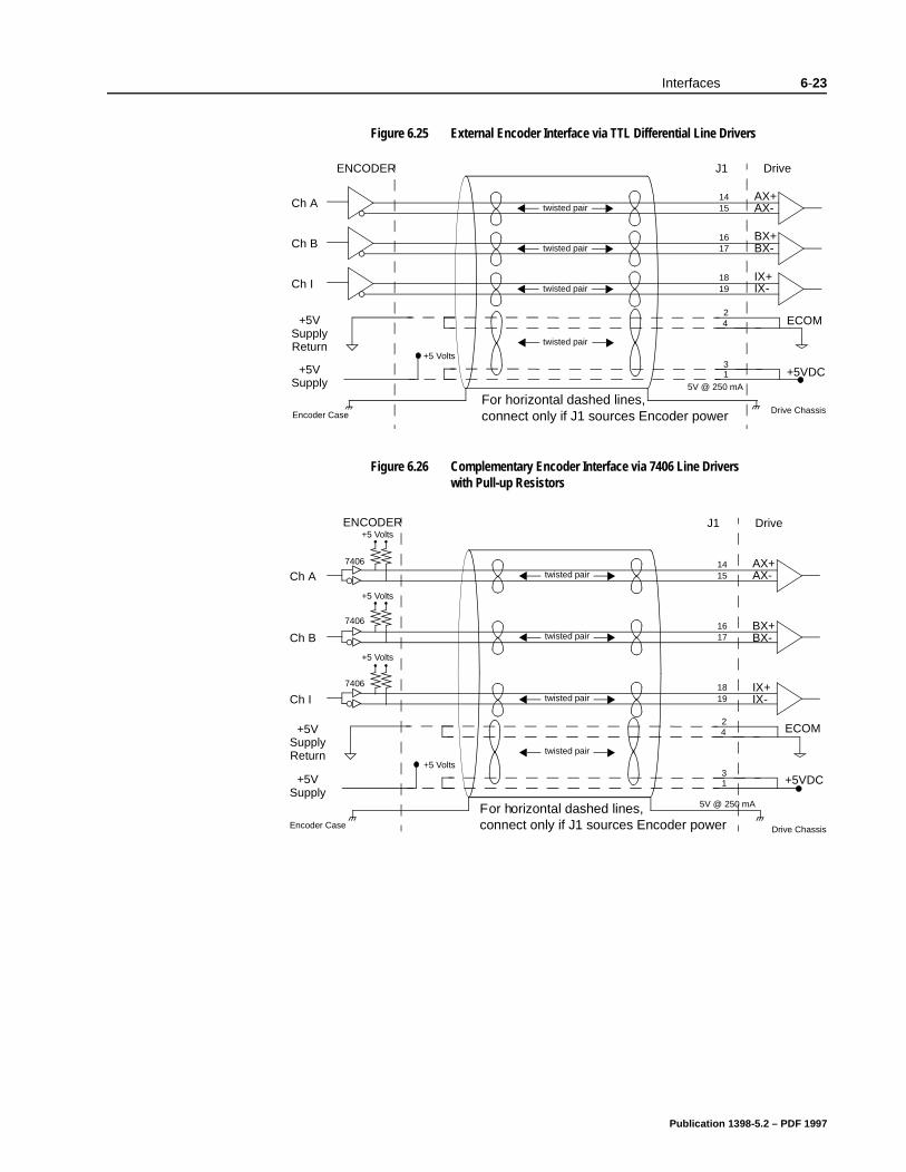
Interfaces 6-23
Figure 6.25 External Encoder Interface via TTL Differential Line Drivers
Figure 6.26 Complementary Encoder Interface via 7406 Line Drivers with Pull-up Resistors
Ch A
ENCODER
AX+AX-
1415
J1 Drive
twisted pair
Ch BBX+BX-
1617twisted pair
Ch IIX+IX-
1819twisted pair
Drive ChassisEncoder Case
24+5V
SupplyReturn
+5 Volts
13+5V
Supply+5VDC
5V @ 250 mA
ECOM
twisted pair
For horizontal dashed lines, connect only if J1 sources Encoder power
ENCODER J1 Drive
Ch BBX+BX-
1617
twisted pair
Drive ChassisEncoder Case
+5 Volts
7406
Ch AAX+AX-
1415
+5 Volts
7406
Ch IIX+IX-
1819
+5 Volts
7406
twisted pair
twisted pair
twisted pair
24+5V
SupplyReturn
+5 Volts
13
+5VSupply
+5VDC
5V @ 250 mA
ECOM
For horizontal dashed lines, connect only if J1 sources Encoder power
Publication 1398-5.2 – PDF 1997
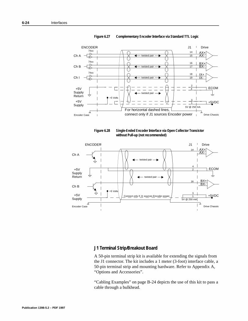
6-24 Interfaces
s a
J1 Terminal Strip/Breakout Board
A 50-pin terminal strip kit is available for extending the signals from the J1 connector. The kit includes a 1 meter (3-foot) interface cable, a 50-pin terminal strip and mounting hardware. Refer to Appendix A, “Options and Accessories”.
“Cabling Examples” on page B-24 depicts the use of this kit to pascable through a bulkhead.
Figure 6.27 Complementary Encoder Interface via Standard TTL Logic
Figure 6.28 Single-Ended Encoder Interface via Open Collector Transistor without Pull-up (not recommended)
Ch AAX+AX-
14
15twisted pair
Ch BBX+BX-
16
17twisted pair
Ch IIX+IX-
18
19twisted pair
Drive ChassisEncoder Case
74xx
74xx
74xx
ENCODER J1 Drive
twisted pair
24+5V
SupplyReturn
+5 Volts
13+5V
Supply+5VDC
5V @ 250 mA
ECOM
For horizontal dashed lines, connect only if J1 sources Encoder power
twisted pair
Ch A
ENCODER
AX+AX-
14
J1 Drive
BX+BX-
16
Drive ChassisEncoder Case
Ch B+5 Volts
13
+5VSupply
+5VDCConnect only if J1 sources Encoder power.5V @ 250 mA
42+5V
SupplyReturn
ECOM
twisted pair
Publication 1398-5.2 – PDF 1997
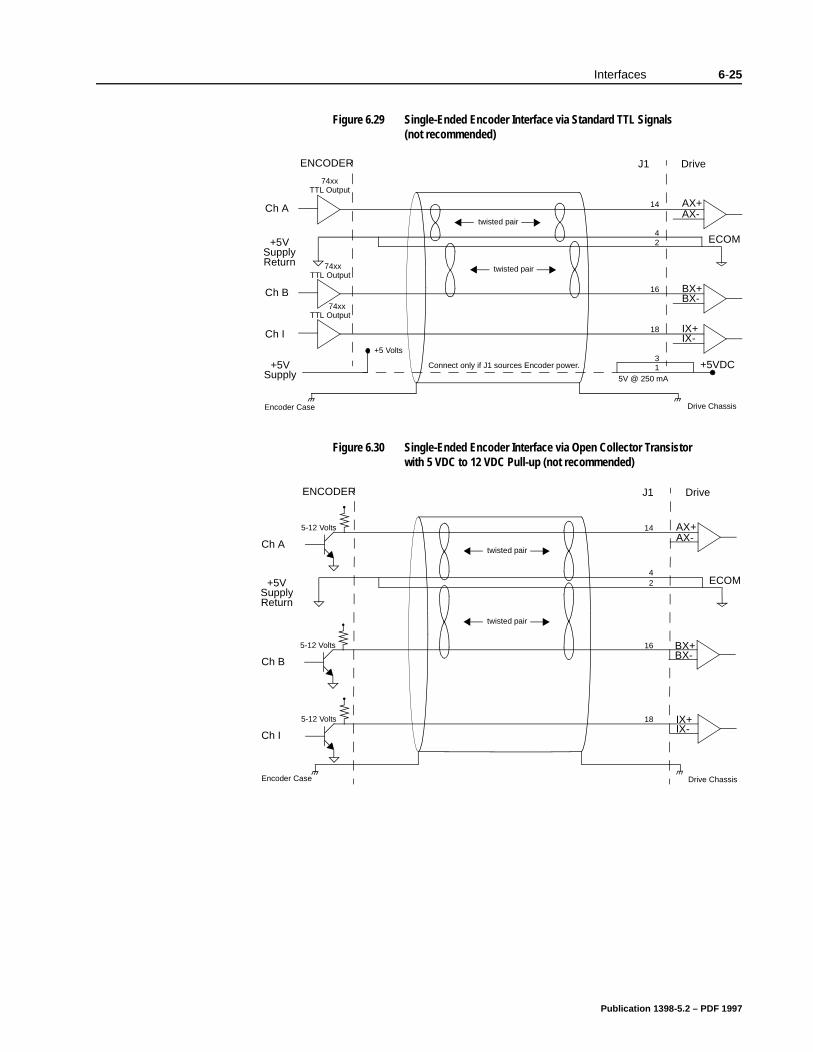
Interfaces 6-25
Figure 6.29 Single-Ended Encoder Interface via Standard TTL Signals (not recommended)
Figure 6.30 Single-Ended Encoder Interface via Open Collector Transistor with 5 VDC to 12 VDC Pull-up (not recommended)
twisted pair
twisted pair
Ch B
ENCODER
BX+BX-
16
J1 Drive
Ch A AX+AX-
14
Drive ChassisEncoder Case
42+5V
SupplyReturn
+5 Volts
13
+5VSupply
+5VDCConnect only if J1 sources Encoder power.
5V @ 250 mA
ECOM
74xxTTL Output
74xxTTL Output
Ch I IX+IX-
18
74xxTTL Output
twisted pair
twisted pair
Ch B
ENCODER
BX+BX-
16
J1 Drive
AX+AX-
14
Drive ChassisEncoder Case
Ch A
5-12 Volts
5-12 Volts
42+5V
SupplyReturn
ECOM
Ch I
IX+IX-
185-12 Volts
Publication 1398-5.2 – PDF 1997
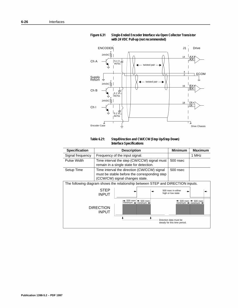
6-26 Interfaces
Figure 6.31 Single-Ended Encoder Interface via Open Collector Transistor with 24 VDC Pull-up (not recommended)
Table 6.21: Step/Direction and CW/CCW (Step Up/Step Down) Interface Specifications
Specification Description Minimum MaximumSignal frequency Frequency of the input signal. 1 MHzPulse Width Time interval the step (CW/CCW) signal must
remain in a single state for detection.500 nsec
Setup Time Time interval the direction (CW/CCW) signal must be stable before the corresponding step (CCW/CW) signal changes state.
500 nsec
The following diagram shows the relationship between STEP and DIRECTION inputs.
twisted pair
twisted pairCh A
ENCODER
AX+AX-
14
J1 Drive
BX+BX-
16
Drive ChassisEncoder Case
Ch B
24VDC
24VDC
42
SupplyReturn
ECOM
IX+IX-
18
Ch I
24VDC
IN7515.1 V
IN7515.1 V
IN7515.1 V
STEPINPUT
DIRECTIONINPUT
Direction data must besteady for this time period.
500 nsecminimum
500 nsecminimum
500 nsec in eitherhigh or low state
500 nsecminimum
500 nsecminimum
Publication 1398-5.2 – PDF 1997
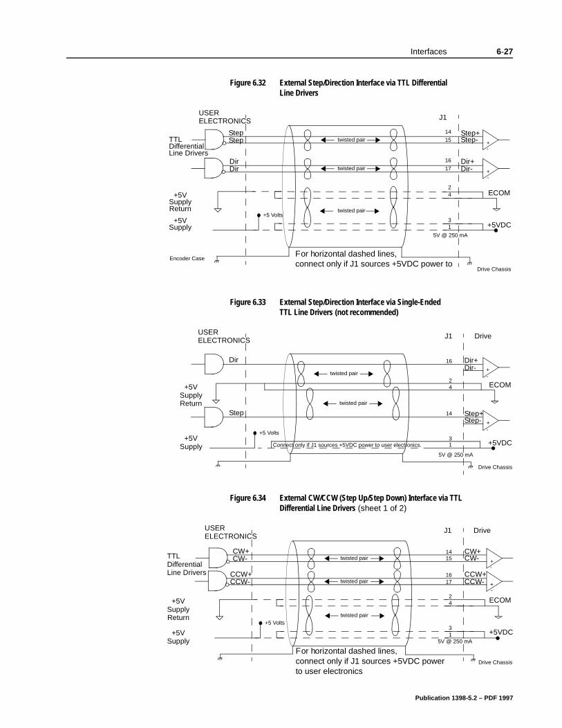
Interfaces 6-27
Figure 6.32 External Step/Direction Interface via TTL Differential Line Drivers
Figure 6.33 External Step/Direction Interface via Single-Ended TTL Line Drivers (not recommended)
Figure 6.34 External CW/CCW (Step Up/Step Down) Interface via TTL Differential Line Drivers (sheet 1 of 2)
TTL
USER
Step+Step-
14
15
J1
twisted pair
Dir+Dir-
16
17twisted pair
Drive Chassis
DifferentialLine Drivers
ELECTRONICS
StepStep
DirDir +
-+
-
twisted pair
Encoder Case
24+5V
SupplyReturn
+5 Volts
13+5V
Supply +5VDC5V @ 250 mA
ECOM
For horizontal dashed lines, connect only if J1 sources +5VDC power to
twisted pair
twisted pair
USER
Step+Step-
14
J1 Drive
Dir+Dir-
16
Drive Chassis
24+5V
SupplyReturn
13+5V
Supply +5VDCConnect only if J1 sources +5VDC power to user electronics.
5V @ 250 mA
ECOM
ELECTRONICS
Step
Dir
-+
-+
+5 Volts
TTL
USER
CW+CW-
1415
J1 Drive
twisted pair
CCW+CCW-
1617twisted pair
Drive Chassis
DifferentialLine Drivers
ELECTRONICS
CW+CW-
CCW+CCW- +
-+
-
twisted pair
24+5V
SupplyReturn
+5 Volts
13
+5VSupply
+5VDC5V @ 250 mA
ECOM
For horizontal dashed lines, connect only if J1 sources +5VDC power to user electronics
Publication 1398-5.2 – PDF 1997
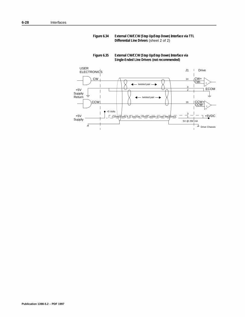
6-28 Interfaces
Figure 6.35 External CW/CCW (Step Up/Step Down) Interface via Single-Ended Line Drivers (not recommended)
Figure 6.34 External CW/CCW (Step Up/Step Down) Interface via TTL Differential Line Drivers (sheet 2 of 2)
twisted pair
twisted pair
USER
CCW+CCW-
16
J1 Drive
CW+CW-
14
Drive Chassis
42+5V
SupplyReturn
+5 Volts
13
+5VSupply
+5VDCConnect only if J1 sources +5VDC power to user electronics.
5V @ 250 mA
ECOM
ELECTRONICS
CCW
CW
-+
-+
Publication 1398-5.2 – PDF 1997
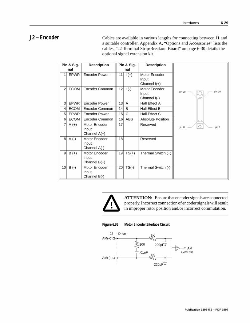
Interfaces 6-29
he e
J2 – Encoder Cables are available in various lengths for connecting between J1 and a suitable controller. Appendix A, “Options and Accessories” lists tcables. “J2 Terminal Strip/Breakout Board” on page 6-30 details thoptional signal extension kit.
Pin & Sig-nal
Description Pin & Sig-nal
Description
1 EPWR Encoder Power 11 I (+) Motor Encoder Input Channel I(+)
2 ECOM Encoder Common 12 I (-) Motor Encoder Input Channel I(-)
3 EPWR Encoder Power 13 A Hall Effect A4 ECOM Encoder Common 14 B Hall Effect B5 EPWR Encoder Power 15 C Hall Effect C
6 ECOM Encoder Common 16 ABS Absolute Position7 A (+) Motor Encoder
Input Channel A(+)
17 Reserved
8 A (-) Motor Encoder Input Channel A(-)
18 Reserved
9 B (+) Motor Encoder Input Channel B(+)
19 TS(+) Thermal Switch (+)
10 B (-) Motor Encoder Input Channel B(-)
20 TS(-) Thermal Switch (-)
pin 10
pin 11
pin 20
pin 1
!
Intro
ATTENTION: Ensure that encoder signals are connected properly. Incorrect connection of encoder signals will result in improper rotor position and/or incorrect commutation.
Figure 6.36 Motor Encoder Interface Circuit
-+AM26LS33
AM(-)
1K
220pF
AM220pF
AM(+)
1K
200
.01uF
DriveJ2
Publication 1398-5.2 – PDF 1997
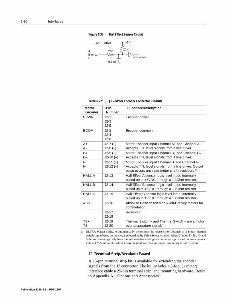
6-30 Interfaces
J2 Terminal Strip/Breakout Board
A 25-pin terminal strip kit is available for extending the encoder signals from the J2 connector. The kit includes a 3-foot (1 meter) interface cable a 25-pin terminal strip, and mounting hardware. Refer to Appendix A, “Options and Accessories”.
Figure 6.37 Hall Effect Sensor Circuit
MC74HC14F
200A,1K
DriveJ2 +5V
B orC
0.1 uF
Table 6.22: J2 – Motor Encoder Connector Pin-Outs
Motor Encoder
Pin Number
Function/Description
EPWR J2-1 J2-3 J2-5
Encoder power.
ECOM J2-2 J2-4 J2-6
Encoder common
A+ A–
J2-7 (+) J2-8 (–)
Motor Encoder Input Channel A+ and Channel A–. Accepts TTL level signals from a line driver.
B+ B–
J2-9 (+) J2-10 (–)
Motor Encoder Input Channel B+ and Channel B–. Accepts TTL level signals from a line driver.
I+ I–
J2-11 (+) J2-12 (–)
Motor Encoder Input Channel I+ and Channel I–. Accepts TTL level signals from a line driver. Output pulse occurs once per motor shaft revolution. a
HALL A J2-13 Hall Effect A sensor logic level input. Internally pulled up to +5VDC through a 1 kOhm resistor.
HALL B J2-14 Hall Effect B sensor logic level input. Internally pulled up to +5VDC through a 1 kOhm resistor.
HALL C J2-15 Hall Effect C sensor logic level input. Internally pulled up to +5VDC through a 1 kOhm resistor.
ABS J2-16 Absolute Position used on Allen-Bradley motors for commutation.
J2-17 J2-18
Reserved
TS+ TS–
J2-19 J2-20
Thermal Switch + and Thermal Switch – are a motor overtemperature signal.a
a. ULTRA Master software automatically determines the presence or absence of a motor thermalswitch signal based on the motor selected in the Drive Select window. Allen-Bradley F-, H-, N- andS-Series motors typically have thermal switches and signal continuity is provided on these motors.LD- and Y-Series motors do not have thermal switches and signal continuity is not required.
Publication 1398-5.2 – PDF 1997
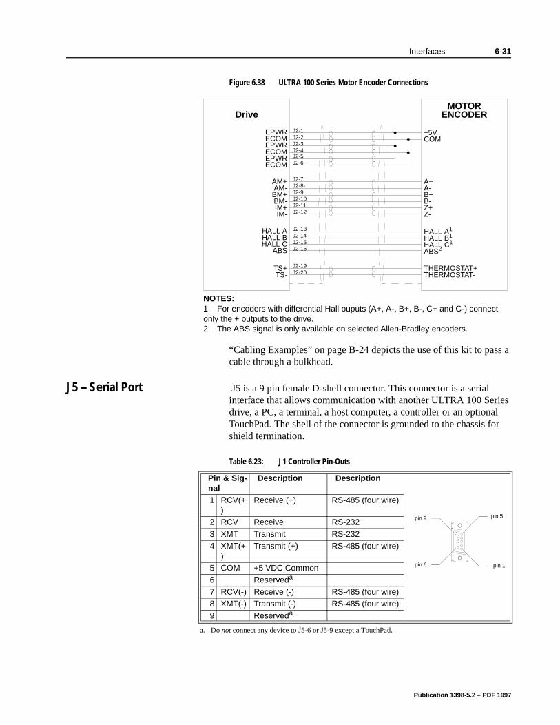
Interfaces 6-31
s a
“Cabling Examples” on page B-24 depicts the use of this kit to pascable through a bulkhead.J5 – Serial Port J5 is a 9 pin female D-shell connector. This connector is a serial interface that allows communication with another ULTRA 100 Series drive, a PC, a terminal, a host computer, a controller or an optional TouchPad. The shell of the connector is grounded to the chassis for shield termination.
Figure 6.38 ULTRA 100 Series Motor Encoder Connections
MOTORENCODERDrive
EPWRECOMEPWRECOMEPWRECOM
AM+AM-BM+BM-IM+IM-
HALL AHALL BHALL C
ABS
TS+TS-
J2-1J2-2J2-3J2-4J2-5J2-6-
J2-7J2-8-J2-9J2-10J2-11J2-12
J2-13J2-14J2-15J2-16
J2-19J2-20
+5VCOM
A+A-B+B-Z+Z-
HALL A1
HALL B1
HALL C1
ABS2
THERMOSTAT+THERMOSTAT-
NOTES:1. For encoders with differential Hall ouputs (A+, A-, B+, B-, C+ and C-) connect only the + outputs to the drive.2. The ABS signal is only available on selected Allen-Bradley encoders.
Table 6.23: J1 Controller Pin-Outs
Pin & Sig-nal
Description Description
1 RCV(+)
Receive (+) RS-485 (four wire)
2 RCV Receive RS-232
3 XMT Transmit RS-2324 XMT(+
)Transmit (+) RS-485 (four wire)
5 COM +5 VDC Common6 Reserveda
7 RCV(-) Receive (-) RS-485 (four wire)8 XMT(-) Transmit (-) RS-485 (four wire)
9 Reserveda
a. Do not connect any device to J5-6 or J5-9 except a TouchPad.
pin 5
pin 6
pin 9
pin 1
Publication 1398-5.2 – PDF 1997
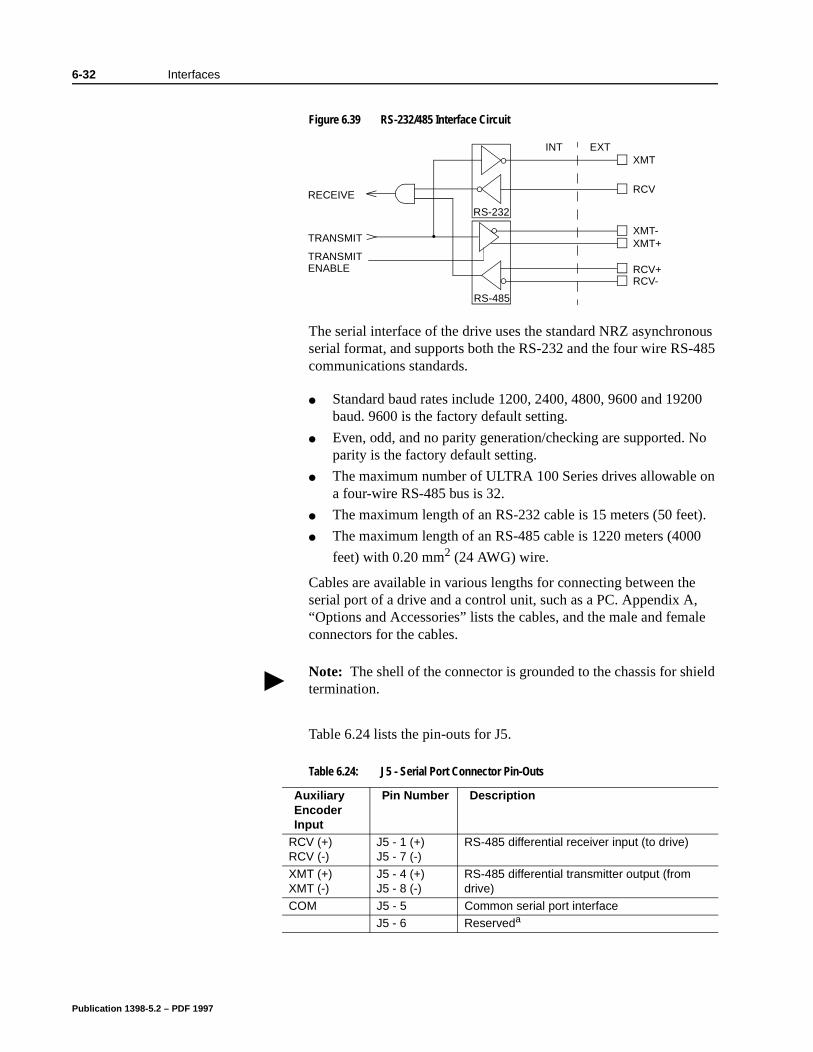
6-32 Interfaces
le
The serial interface of the drive uses the standard NRZ asynchronous serial format, and supports both the RS-232 and the four wire RS-485 communications standards.
Standard baud rates include 1200, 2400, 4800, 9600 and 19200 baud. 9600 is the factory default setting.
Even, odd, and no parity generation/checking are supported. No parity is the factory default setting.
The maximum number of ULTRA 100 Series drives allowable on a four-wire RS-485 bus is 32.
The maximum length of an RS-232 cable is 15 meters (50 feet).
The maximum length of an RS-485 cable is 1220 meters (4000
feet) with 0.20 mm2 (24 AWG) wire.
Cables are available in various lengths for connecting between the serial port of a drive and a control unit, such as a PC. Appendix A, “Options and Accessories” lists the cables, and the male and femaconnectors for the cables.
Table 6.24 lists the pin-outs for J5.
Figure 6.39 RS-232/485 Interface Circuit
EXTINTXMT
RCV
XMT-XMT+
RCV+RCV-
RS-232
RS-485
TRANSMIT
RECEIVE
TRANSMITENABLE
Note: The shell of the connector is grounded to the chassis for shield termination.
Table 6.24: J5 - Serial Port Connector Pin-Outs
Auxiliary Encoder Input
Pin Number Description
RCV (+)RCV (-)
J5 - 1 (+)J5 - 7 (-)
RS-485 differential receiver input (to drive)
XMT (+) XMT (-)
J5 - 4 (+)J5 - 8 (-)
RS-485 differential transmitter output (from drive)
COM J5 - 5 Common serial port interfaceJ5 - 6 Reserveda
Publication 1398-5.2 – PDF 1997
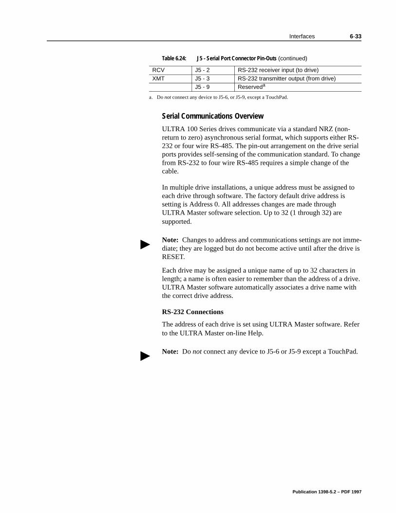
Interfaces 6-33
Serial Communications Overview
ULTRA 100 Series drives communicate via a standard NRZ (non-return to zero) asynchronous serial format, which supports either RS-232 or four wire RS-485. The pin-out arrangement on the drive serial ports provides self-sensing of the communication standard. To change from RS-232 to four wire RS-485 requires a simple change of the cable.
In multiple drive installations, a unique address must be assigned to each drive through software. The factory default drive address is setting is Address 0. All addresses changes are made through ULTRA Master software selection. Up to 32 (1 through 32) are supported.
Each drive may be assigned a unique name of up to 32 characters in length; a name is often easier to remember than the address of a drive. ULTRA Master software automatically associates a drive name with the correct drive address.
RS-232 Connections
The address of each drive is set using ULTRA Master software. Refer to the ULTRA Master on-line Help.
RCV J5 - 2 RS-232 receiver input (to drive)
XMT J5 - 3 RS-232 transmitter output (from drive)J5 - 9 Reserveda
a. Do not connect any device to J5-6, or J5-9, except a TouchPad.
Table 6.24: J5 - Serial Port Connector Pin-Outs (continued)
Note: Changes to address and communications settings are not imme-diate; they are logged but do not become active until after the drive is RESET.
Note: Do not connect any device to J5-6 or J5-9 except a TouchPad.
Publication 1398-5.2 – PDF 1997
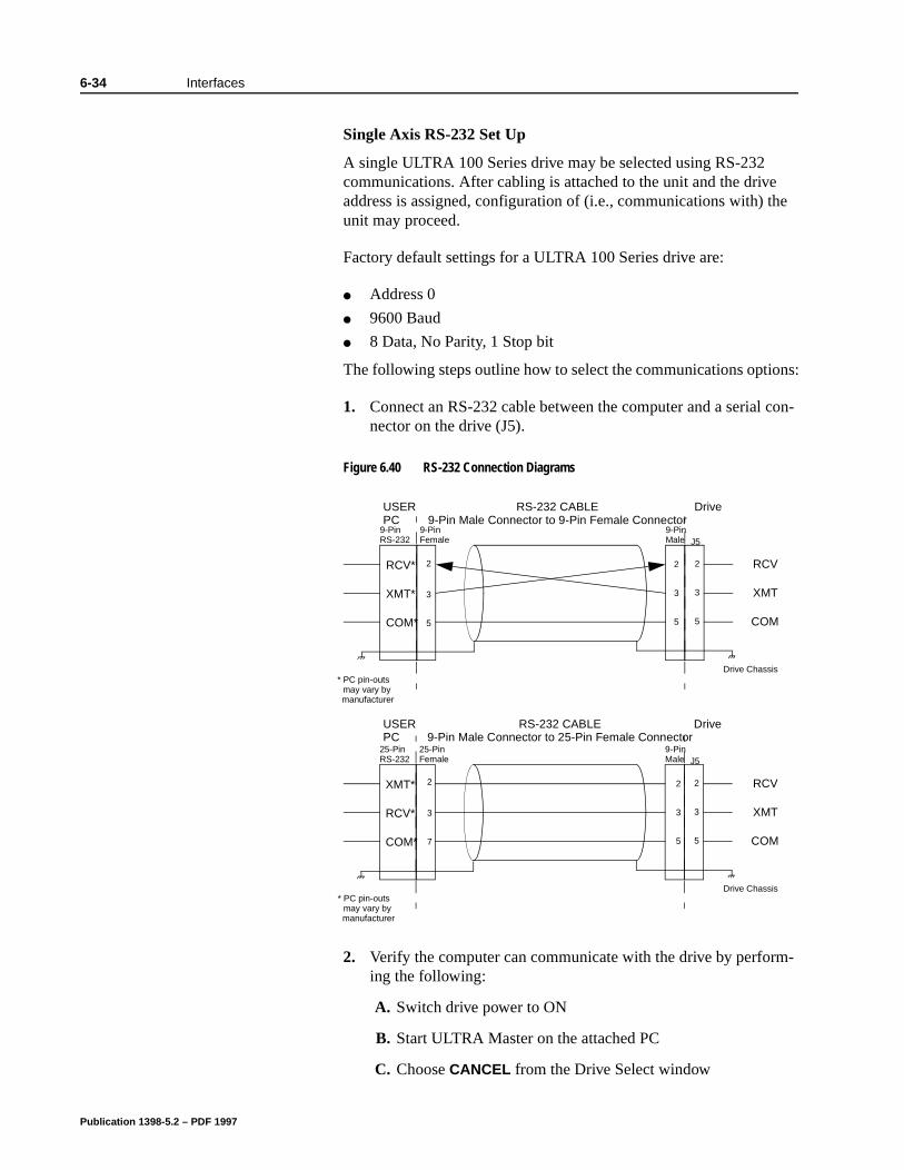
6-34 Interfaces
Single Axis RS-232 Set Up
A single ULTRA 100 Series drive may be selected using RS-232 communications. After cabling is attached to the unit and the drive address is assigned, configuration of (i.e., communications with) the unit may proceed.
Factory default settings for a ULTRA 100 Series drive are:
Address 0
9600 Baud
8 Data, No Parity, 1 Stop bit
The following steps outline how to select the communications options:
1. Connect an RS-232 cable between the computer and a serial con-nector on the drive (J5).
2. Verify the computer can communicate with the drive by perform-ing the following:
A. Switch drive power to ON
B. Start ULTRA Master on the attached PC
C. Choose CANCEL from the Drive Select window
Figure 6.40 RS-232 Connection Diagrams
USER
2
9-Pin
Drive
2
Drive Chassis
PC
33
5
Male
RS-232 CABLE
J5
2
3
5
RCV
XMT
COM
RCV*
XMT*
COM*
* PC pin-outs may vary by manufacturer
9-PinFemale
9-Pin Male Connector to 9-Pin Female Connector9-PinRS-232
USER
2
9-Pin
Drive
2
Drive Chassis
PC
33
57
Male
RS-232 CABLE
J5
2
3
5
RCV
XMT
COM
XMT*
RCV*
COM*
25-PinFemale
9-Pin Male Connector to 25-Pin Female Connector25-PinRS-232
5
* PC pin-outs may vary by manufacturer
Publication 1398-5.2 – PDF 1997
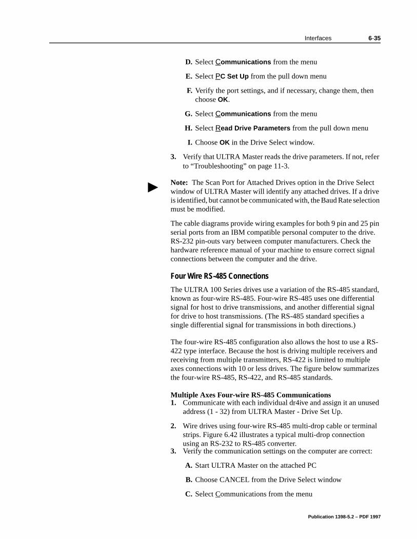
Interfaces 6-35
pin e. e nal
ard, al al
S-nd
izes
ed
l
:
D. Select Communications from the menu
E. Select PC Set Up from the pull down menu
F. Verify the port settings, and if necessary, change them, then choose OK.
G. Select Communications from the menu
H. Select Read Drive Parameters from the pull down menu
I. Choose OK in the Drive Select window.
3. Verify that ULTRA Master reads the drive parameters. If not, refer to “Troubleshooting” on page 11-3.
The cable diagrams provide wiring examples for both 9 pin and 25serial ports from an IBM compatible personal computer to the drivRS-232 pin-outs vary between computer manufacturers. Check thhardware reference manual of your machine to ensure correct sigconnections between the computer and the drive.
Four Wire RS-485 Connections
The ULTRA 100 Series drives use a variation of the RS-485 standknown as four-wire RS-485. Four-wire RS-485 uses one differentisignal for host to drive transmissions, and another differential signfor drive to host transmissions. (The RS-485 standard specifies a single differential signal for transmissions in both directions.)
The four-wire RS-485 configuration also allows the host to use a R422 type interface. Because the host is driving multiple receivers areceiving from multiple transmitters, RS-422 is limited to multiple axes connections with 10 or less drives. The figure below summarthe four-wire RS-485, RS-422, and RS-485 standards.
Multiple Axes Four-wire RS-485 Communications 1. Communicate with each individual dr4ive and assign it an unus
address (1 - 32) from ULTRA Master - Drive Set Up.
2. Wire drives using four-wire RS-485 multi-drop cable or terminastrips. Figure 6.42 illustrates a typical multi-drop connection using an RS-232 to RS-485 converter.
3. Verify the communication settings on the computer are correct
A. Start ULTRA Master on the attached PC
B. Choose CANCEL from the Drive Select window
C. Select Communications from the menu
Note: The Scan Port for Attached Drives option in the Drive Select window of ULTRA Master will identify any attached drives. If a drive is identified, but cannot be communicated with, the Baud Rate selection must be modified.
Publication 1398-5.2 – PDF 1997
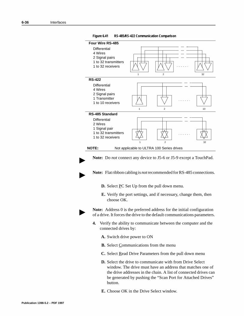
6-36 Interfaces
s”
D. Select PC Set Up from the pull down menu.
E. Verify the port settings, and if necessary, change them, then choose OK.
4. Verify the ability to communicate between the computer and the connected drives by:
A. Switch drive power to ON
B. Select Communications from the menu
C. Select Read Drive Parameters from the pull down menu
D. Select the drive to communicate with from Drive Select window. The drive must have an address that matches one of the drive addresses in the chain. A list of connected drives can be generated by pushing the “Scan Port for Attached Drivebutton.
E. Choose OK in the Drive Select window.
Figure 6.41 RS-485/RS-422 Communication Comparison
Four Wire RS-485
Differential4 Wires2 Signal pairs1 to 32 transmitters1 to 32 receivers
RS-422
Differential4 Wires2 Signal pairs1 Transmitter1 to 10 receivers
RS-485 Standard
Differential2 Wires1 Signal pair1 to 32 transmitters1 to 32 receivers
NOTE: Not applicable to ULTRA 100 Series drives
Note: Do not connect any device to J5-6 or J5-9 except a TouchPad.
Note: Flat ribbon cabling is not recommended for RS-485 connections.
1 2 32
1 2 10
1 2 32
Note: Address 0 is the preferred address for the initial configuration of a drive. It forces the drive to the default communications parameters.
Publication 1398-5.2 – PDF 1997

Interfaces 6-37
5. Verify that ULTRA Master loads the drive parameters. If not, refer to the troubleshooting section.
6. Repeat the preceding two steps for each additional drive.
Publication 1398-5.2 – PDF 1997
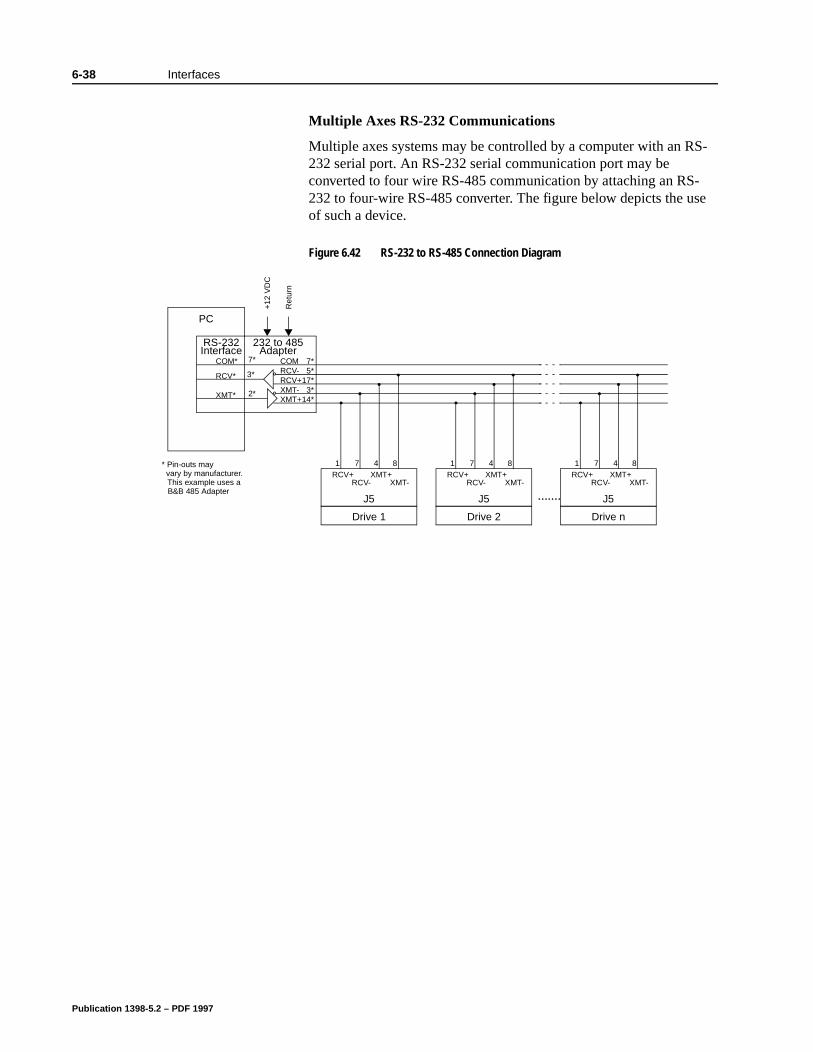
6-38 Interfaces
Multiple Axes RS-232 Communications
Multiple axes systems may be controlled by a computer with an RS-232 serial port. An RS-232 serial communication port may be converted to four wire RS-485 communication by attaching an RS-232 to four-wire RS-485 converter. The figure below depicts the use of such a device.
Figure 6.42 RS-232 to RS-485 Connection Diagram
PC
* Pin-outs may vary by manufacturer. This example uses a
Drive 1
RCV+RCV-
XMT+
J5
1 7 4 8
XMT-
COMRCV-RCV+XMT-XMT+
Drive 2
RCV+RCV-
XMT+
J5
1 7 4 8
XMT-
Drive n
RCV+RCV-
XMT+
J5
1 7 4 8
XMT-
232 to 485Adapter
.......
7* 5*17* 3*14*
3*
2*
7*COM*
RCV*
XMT*
RS-232Interface
+12
VD
C
Ret
urn
B&B 485 Adapter
Publication 1398-5.2 – PDF 1997
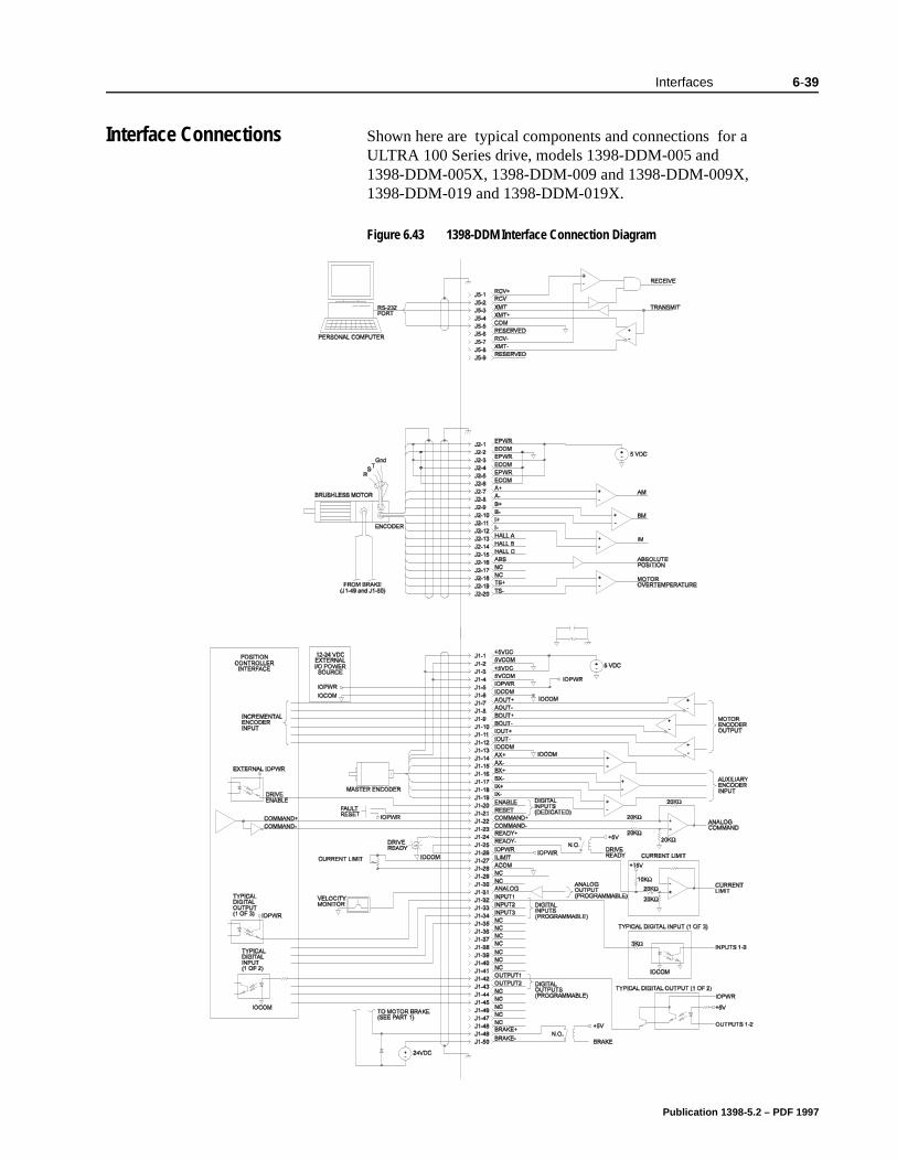
Interfaces 6-39
Interface Connections Shown here are typical components and connections for a ULTRA 100 Series drive, models 1398-DDM-005 and 1398-DDM-005X, 1398-DDM-009 and 1398-DDM-009X, 1398-DDM-019 and 1398-DDM-019X.
Figure 6.43 1398-DDM Interface Connection DiagramIntro
-
-
-
Publication 1398-5.2 – PDF 1997

6-40 Interfaces
Publication 1398-5.2 – PDF 1997
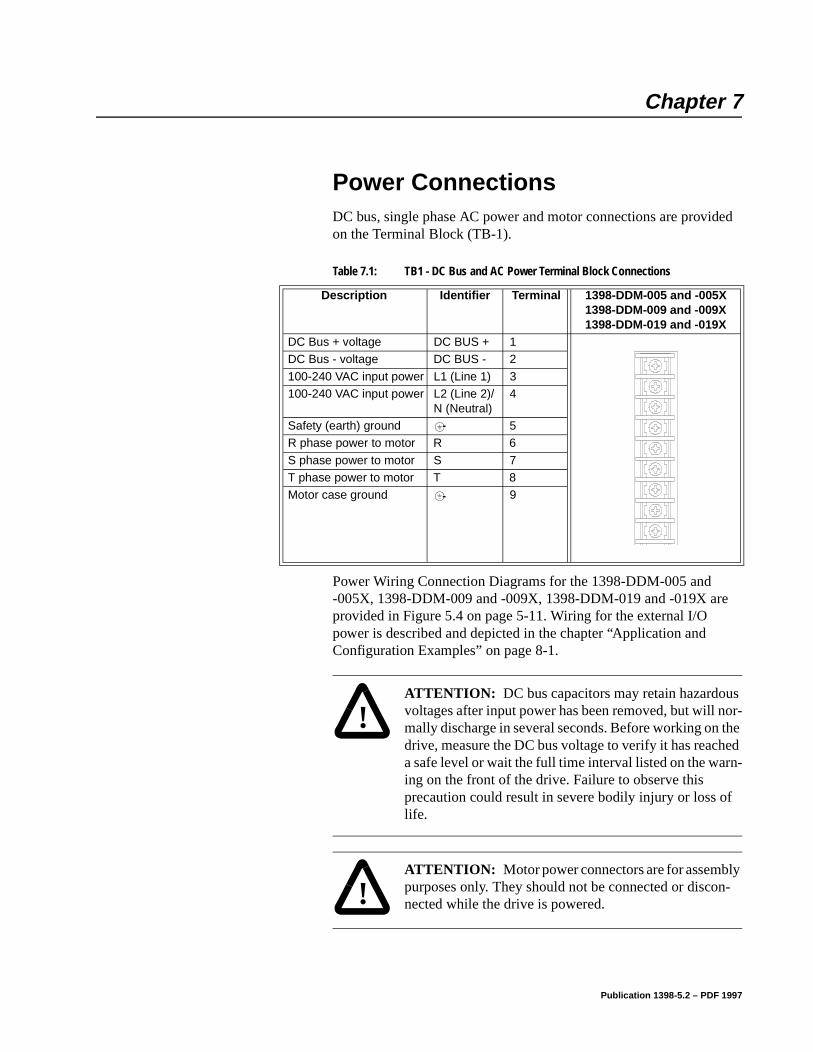
Chapter 7
Power Connections Chapter 7
DC bus, single phase AC power and motor connections are provided on the Terminal Block (TB-1).
Power Wiring Connection Diagrams for the 1398-DDM-005 and -005X, 1398-DDM-009 and -009X, 1398-DDM-019 and -019X are provided in Figure 5.4 on page 5-11. Wiring for the external I/O power is described and depicted in the chapter “Application and Configuration Examples” on page 8-1.
Table 7.1: TB1 - DC Bus and AC Power Terminal Block Connections
Description Identifier Terminal 1398-DDM-005 and -005X1398-DDM-009 and -009X1398-DDM-019 and -019X
DC Bus + voltage DC BUS + 1DC Bus - voltage DC BUS - 2
100-240 VAC input power L1 (Line 1) 3100-240 VAC input power L2 (Line 2)/
N (Neutral)4
Safety (earth) ground 5R phase power to motor R 6
S phase power to motor S 7T phase power to motor T 8Motor case ground 9
!
Intro
ATTENTION: DC bus capacitors may retain hazardous voltages after input power has been removed, but will nor-mally discharge in several seconds. Before working on the drive, measure the DC bus voltage to verify it has reached a safe level or wait the full time interval listed on the warn-ing on the front of the drive. Failure to observe this precaution could result in severe bodily injury or loss of life.
!
Intro
ATTENTION: Motor power connectors are for assembly purposes only. They should not be connected or discon-nected while the drive is powered.
Publication 1398-5.2 – PDF 1997
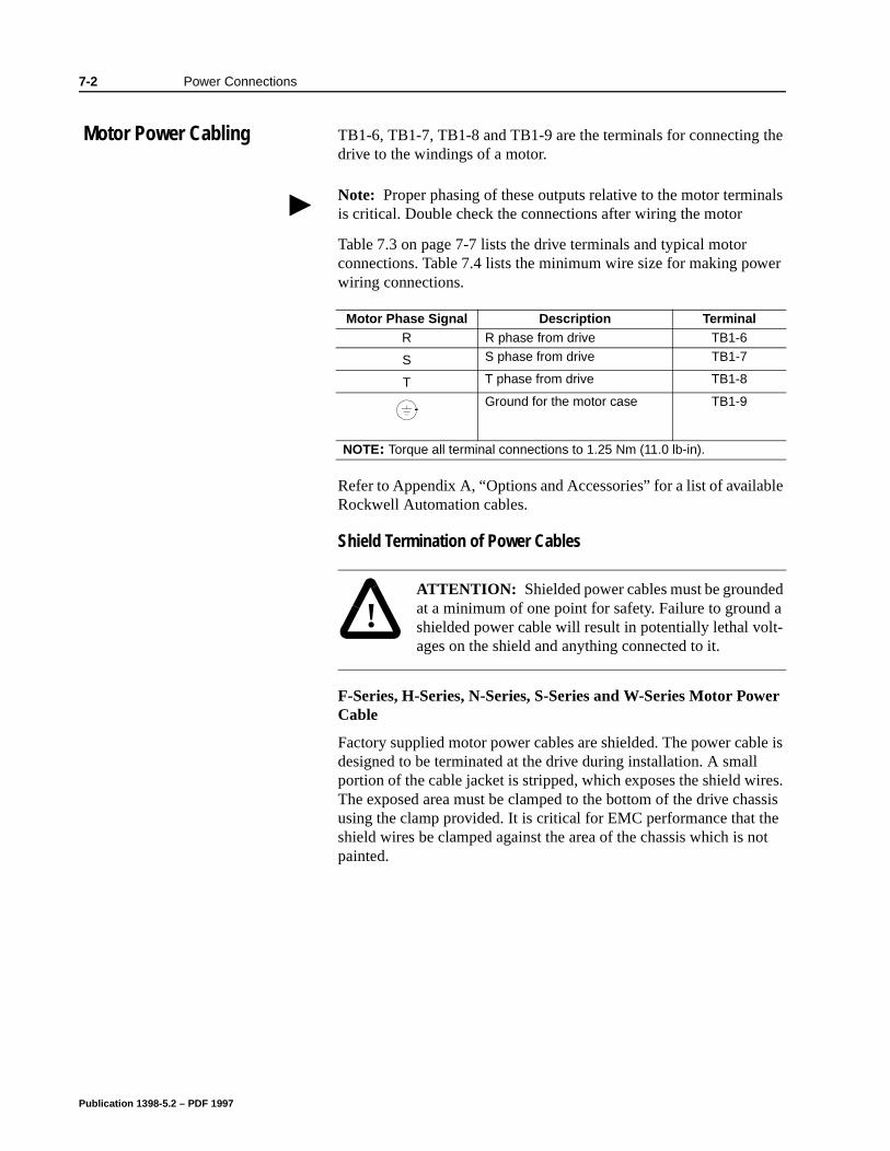
7-2 Power Connections
le
le is
res. ssis e ot
Motor Power Cabling TB1-6, TB1-7, TB1-8 and TB1-9 are the terminals for connecting the drive to the windings of a motor.
Table 7.3 on page 7-7 lists the drive terminals and typical motor connections. Table 7.4 lists the minimum wire size for making power wiring connections.
Refer to Appendix A, “Options and Accessories” for a list of availabRockwell Automation cables.
Shield Termination of Power Cables
F-Series, H-Series, N-Series, S-Series and W-Series Motor Power Cable
Factory supplied motor power cables are shielded. The power cabdesigned to be terminated at the drive during installation. A small portion of the cable jacket is stripped, which exposes the shield wiThe exposed area must be clamped to the bottom of the drive chausing the clamp provided. It is critical for EMC performance that thshield wires be clamped against the area of the chassis which is npainted.
Note: Proper phasing of these outputs relative to the motor terminals is critical. Double check the connections after wiring the motor
Motor Phase Signal Description TerminalR R phase from drive TB1-6
S S phase from drive TB1-7
T T phase from drive TB1-8
Ground for the motor case TB1-9
NOTE: Torque all terminal connections to 1.25 Nm (11.0 lb-in).
!
Intro
ATTENTION: Shielded power cables must be grounded at a minimum of one point for safety. Failure to ground a shielded power cable will result in potentially lethal volt-ages on the shield and anything connected to it.
Publication 1398-5.2 – PDF 1997
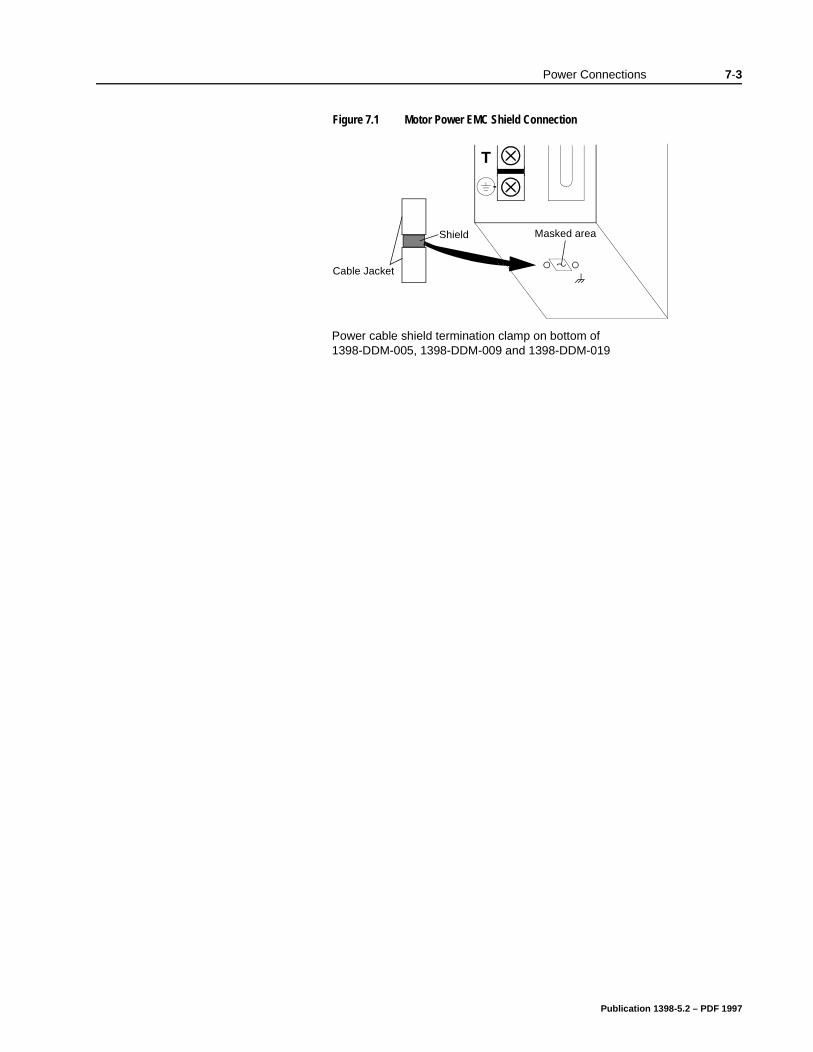
Power Connections 7-3
Figure 7.1 Motor Power EMC Shield Connection
Masked areaShield
Cable Jacket
T
Power cable shield termination clamp on bottom of 1398-DDM-005, 1398-DDM-009 and 1398-DDM-019
Publication 1398-5.2 – PDF 1997
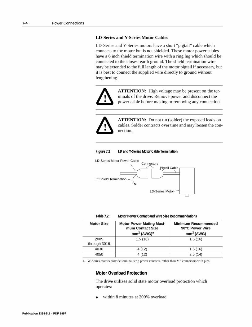
7-4 Power Connections
les be
but
LD-Series and Y-Series Motor Cables
LD-Series and Y-Series motors have a short “pigtail” cable which connects to the motor but is not shielded. These motor power cabhave a 6 inch shield termination wire with a ring lug which should connected to the closest earth ground. The shield termination wiremay be extended to the full length of the motor pigtail if necessary,it is best to connect the supplied wire directly to ground without lengthening.
Motor Overload Protection
The drive utilizes solid state motor overload protection which operates:
within 8 minutes at 200% overload
!
Intro
ATTENTION: High voltage may be present on the ter-minals of the drive. Remove power and disconnect the power cable before making or removing any connection.
!
Intro
ATTENTION: Do not tin (solder) the exposed leads on cables. Solder contracts over time and may loosen the con-nection.
Figure 7.2 LD and Y-Series Motor Cable Termination
6” Shield Termination
LD-Series Motor Power CableConnectors
Pigtail Cable
LD-Series Motor
Table 7.2: Motor Power Contact and Wire Size Recommendations
Motor Size Motor Power Mating Maxi-mum Contact Size
mm2 (AWG)a
Minimum Recommended 90°C Power Wire
mm2 (AWG)2005
through 30161.5 (16) 1.5 (16)
4030 4 (12) 1.5 (16)4050 4 (12) 2.5 (14)
a. W-Series motors provide terminal strip power contacts, rather than MS connectors with pins.
Publication 1398-5.2 – PDF 1997
Power Connections 7-5
elf
the
ent s, can
nce
within 20 seconds at 600% overload
Power Supply Protection
The feedback encoder, auxiliary encoder and optional TouchPad are powered by a single internal power supply. The power supply has a “resettable” fuse that opens at 3 amps and automatically resets itswhen the current falls below 3 amps.There are no internal fuses requiring replacement.
Emergency Stop Wiring
An overlapping contactor may be inserted between the motor anddrive for emergency stop purposes. The contactor must not simplybreak the motor current, it also must switch a three phase resistiveload in parallel with the motor windings.
The three resistors provide dynamic braking. In addition, they prevcontinuous arcing at the main contacts when breaking DC currentsuch as when the motor stalls. Simply breaking the motor current result in high voltages due to motor inductance, which will cause prolonged arcing in the contactor. In extreme cases, the prolongedarcing could result in the contactor catching fire. An overlapping contactor provides the required timing by engaging the braking contactors before the drive contactors disengage.
Figure 7.3 depicts a contactor installation with resistive loads. Guidelines for the installation include:
Resistor values should be one to four times the winding resistafor good braking performance. Refer to Appendix F, “DynamicBraking Resistor Selection” for resistor sizing equations.
Screen and ground cables should be connected as shown.
Shields should be unbraided (not a drain wire soldered to the shield).
Connection lengths should be minimized.
Safety ground (GND) and shield connections are permanentlyconnected. This is essential for electrical safety.
EMC guidelines require connection of the shield at the point where the contactor is inserted.
Publication 1398-5.2 – PDF 1997
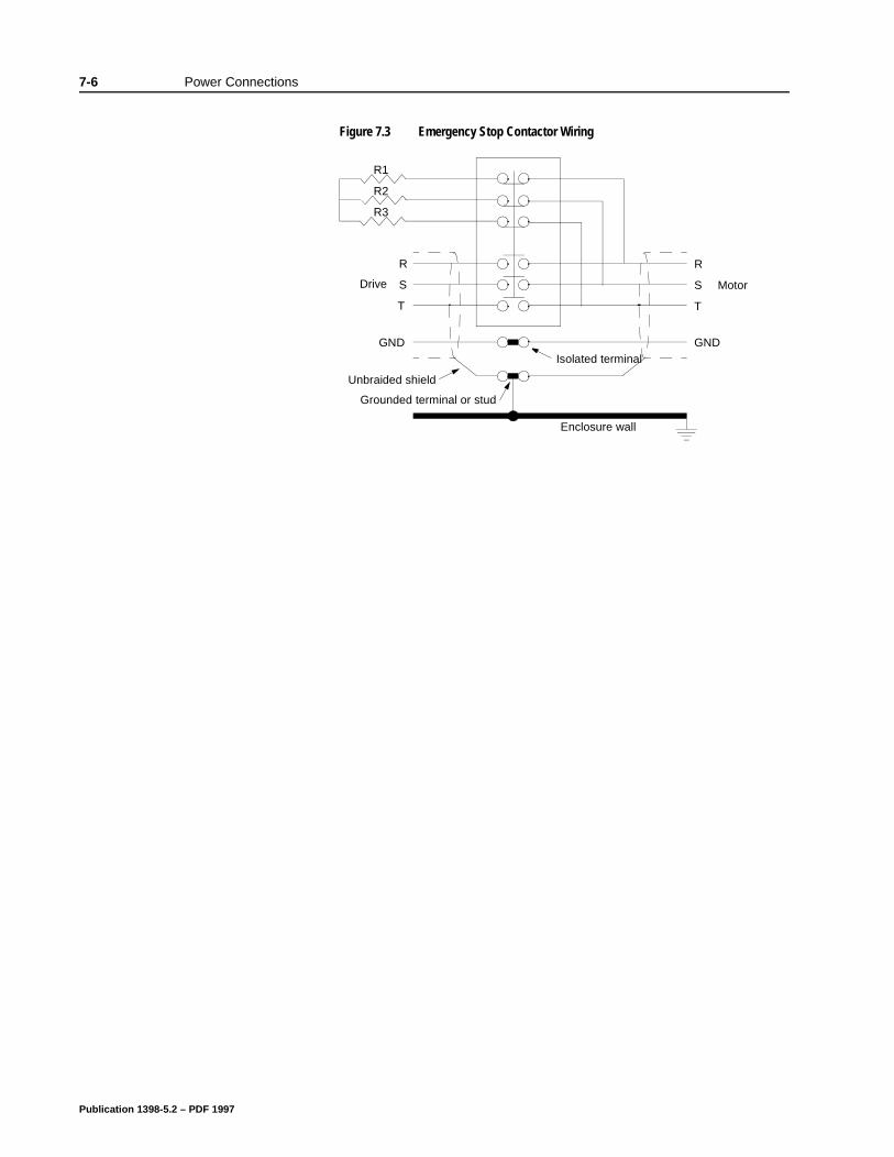
7-6 Power Connections
Figure 7.3 Emergency Stop Contactor Wiring
R
S
T
Drive
R
S
T
Motor
GNDGNDIsolated terminal
Grounded terminal or stud
Unbraided shield
Enclosure wall
R3
R2
R1
Publication 1398-5.2 – PDF 1997
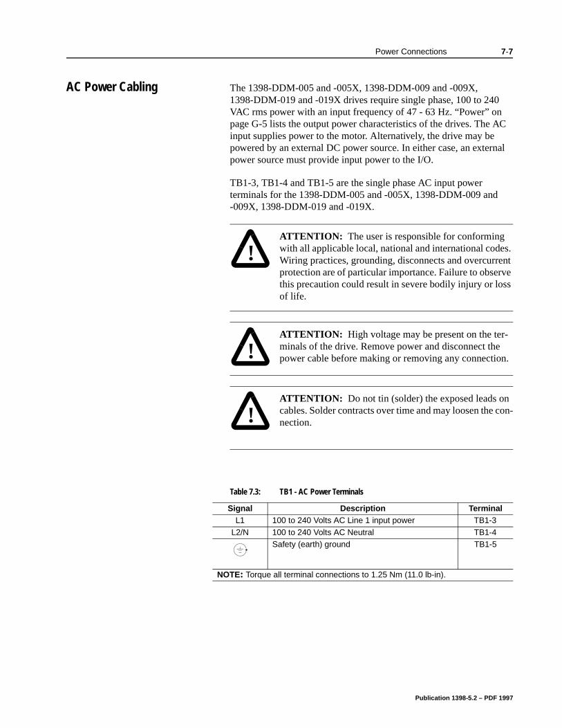
Power Connections 7-7
C
nal
AC Power Cabling The 1398-DDM-005 and -005X, 1398-DDM-009 and -009X, 1398-DDM-019 and -019X drives require single phase, 100 to 240 VAC rms power with an input frequency of 47 - 63 Hz. “Power” on page G-5 lists the output power characteristics of the drives. The Ainput supplies power to the motor. Alternatively, the drive may be powered by an external DC power source. In either case, an exterpower source must provide input power to the I/O.
TB1-3, TB1-4 and TB1-5 are the single phase AC input power terminals for the 1398-DDM-005 and -005X, 1398-DDM-009 and -009X, 1398-DDM-019 and -019X.
!
Intro
ATTENTION: The user is responsible for conforming with all applicable local, national and international codes. Wiring practices, grounding, disconnects and overcurrent protection are of particular importance. Failure to observe this precaution could result in severe bodily injury or loss of life.
!
Intro
ATTENTION: High voltage may be present on the ter-minals of the drive. Remove power and disconnect the power cable before making or removing any connection.
!
Intro
ATTENTION: Do not tin (solder) the exposed leads on cables. Solder contracts over time and may loosen the con-nection.
Table 7.3: TB1 - AC Power Terminals
Signal Description TerminalL1 100 to 240 Volts AC Line 1 input power TB1-3
L2/N 100 to 240 Volts AC Neutral TB1-4 Safety (earth) ground TB1-5
NOTE: Torque all terminal connections to 1.25 Nm (11.0 lb-in).
Publication 1398-5.2 – PDF 1997
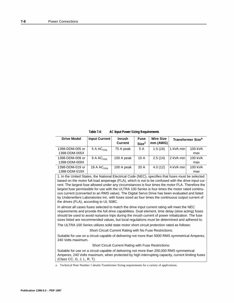
7-8 Power Connections
Table 7.4: AC Input Power Sizing Requirements
Drive Model Input Current Inrush Current
Fuse
Size1Wire Size
mm (AWG)Transformer Sizea
1398-DDM-005 or 1398-DDM-005X
5 A ACrms 75 A peak 5 A 1.5 (16) 1 kVA min 100 kVA max
1398-DDM-009 or 1398-DDM-009X
9 A ACrms 100 A peak 10 A 2.5 (14) 2 kVA min 100 kVA max
1398-DDM-019 or 1398-DDM-019X
18 A ACrms 100 A peak 20 A 4.0 (12) 4 kVA min 100 kVA max
1. In the United States, the National Electrical Code (NEC), specifies that fuses must be selected based on the motor full load amperage (FLA), which is not to be confused with the drive input cur-rent. The largest fuse allowed under any circumstances is four times the motor FLA. Therefore the largest fuse permissible for use with the ULTRA 100 Series is four times the motor rated continu-ous current (converted to an RMS value). The Digital Servo Drive has been evaluated and listed by Underwriters Laboratories Inc. with fuses sized as four times the continuous output current of the drives (FLA), according to UL 508C.
In almost all cases fuses selected to match the drive input current rating will meet the NEC requirements and provide the full drive capabilities. Dual element, time delay (slow acting) fuses should be used to avoid nuisance trips during the inrush current of power initialization. The fuse sizes listed are recommended values, but local regulations must be determined and adhered to.
The ULTRA 100 Series utilizes solid state motor short circuit protection rated as follows:
Short Circuit Current Rating with No Fuse Restrictions:
Suitable for use on a circuit capable of delivering not more than 5000 RMS symmetrical Amperes, 240 Volts maximum.
Short Circuit Current Rating with Fuse Restrictions:
Suitable for use on a circuit capable of delivering not more than 200,000 RMS symmetrical Amperes, 240 Volts maximum, when protected by high interrupting capacity, current limiting fuses (Class CC, G, J, L, R, T).
a. Technical Note Number 1 details Transformer Sizing requirements for a variety of applications.
Publication 1398-5.2 – PDF 1997
Power Connections 7-9
DC Bus TB1-1 and TB1-2 are the DC Bus connections for an external shunt.
!
Intro
ATTENTION: External shunt resistors connect directly to the power bus. For safety reasons, external shunt resis-tors must be enclosed.
!
Intro
ATTENTION: DC bus capacitors may retain hazardous voltages after input power has been removed, but will nor-mally discharge in several seconds. Before working on the drive, measure the DC bus voltage to verify it has reached a safe level or wait the full time interval listed on the warn-ing on the front of the drive. Failure to observe this precaution could result in severe bodily injury or loss of life.
!
Intro
ATTENTION: Do not connect an external I/O power sup-ply to the DC Bus. The DC+ and DC- terminals connect directly to the power bus of the drive.
Publication 1398-5.2 – PDF 1997

7-10 Power Connections
Publication 1398-5.2 – PDF 1997
Chapter 8
nd in
nec-
, T
ng
Application and Configuration Examples Chapter 8
This section explains how to install and verify the ULTRA 100 Series drive for various modes of operation. The procedures verify the installation by:
Showing how the power and logic wiring is connected.
Selecting the Operation Mode setup for the drive.
Tuning the drive for a particular motor type and size.
Verifying the basic functionality of the drive and motor combination.
How to modify the units of measurement for ULTRA Master displays is explained on page 8-50.
Analog Control The ULTRA 100 Series drive can be set up as an analog drive in either the Velocity or Torque mode by making the hardware connections and performing the software setup and tuning described below. The connection diagram depicts the minimum hardware necessary. Interfacing the drive to an external controller requires similar circuitry from the controller to J1. Instructions are provided to configure the drive using a PC with ULTRA Master software, but the optional TouchPad also may be used.
Hardware Set Up
Make the connections described below and shown in the figure.
1. Connect a ±10VDC power source between J1-22 and J1-23 (ANALOG CMND +/-) to provide the analog speed or torque command.
2. Connect an RS-232 cable between the serial port on the PC athe J4 connector on the drive. A simple 3 wire cable is depictedthe figure below.
3. Connect a Motor/Feedback cable from the motor to the J2 contor on the drive.
4. Connect a Power cable from the motor to TB1 (terminals R, S
and ) on the drive.
5. Connect a jumper wire with a toggle switch between the followipins:
• J1-20 (ENABLE) and J1-26 (I/O PWR)
Publication 1398-5.2 – PDF 1997
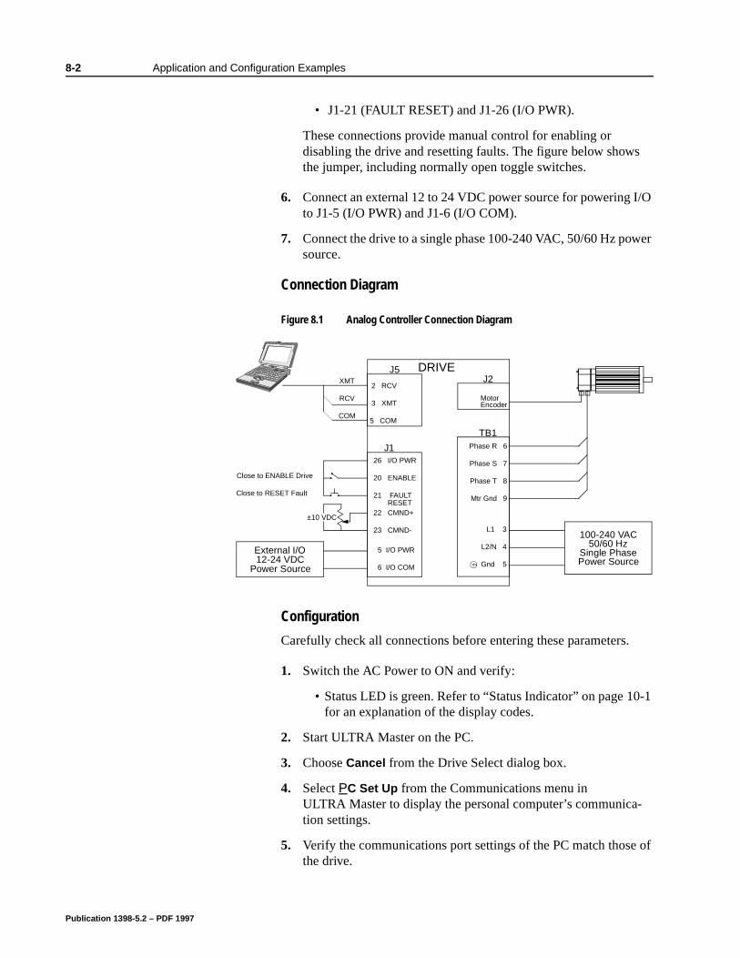
8-2 Application and Configuration Examples
s
I/O
wer
-1
-
of
• J1-21 (FAULT RESET) and J1-26 (I/O PWR).
These connections provide manual control for enabling or disabling the drive and resetting faults. The figure below showthe jumper, including normally open toggle switches.
6. Connect an external 12 to 24 VDC power source for powering to J1-5 (I/O PWR) and J1-6 (I/O COM).
7. Connect the drive to a single phase 100-240 VAC, 50/60 Hz posource.
Connection Diagram
Configuration
Carefully check all connections before entering these parameters.
1. Switch the AC Power to ON and verify:
• Status LED is green. Refer to “Status Indicator” on page 10for an explanation of the display codes.
2. Start ULTRA Master on the PC.
3. Choose Cancel from the Drive Select dialog box.
4. Select PC Set Up from the Communications menu in ULTRA Master to display the personal computer’s communication settings.
5. Verify the communications port settings of the PC match thosethe drive.
Figure 8.1 Analog Controller Connection Diagram
J126 I/O PWR
20 ENABLE
21 FAULT
22 CMND+
23 CMND-
Close to ENABLE Drive
Close to RESET Fault
±10 VDC
DRIVE
L1 3
L2/N 4
Gnd 5
100-240 VAC50/60 Hz
Single PhasePower Source
RESET
J5
2 RCV
3 XMT
5 COM
XMT
RCV
COM
TB1Phase R 6
Phase S 7
Phase T 8
Mtr Gnd 9
J2
MotorEncoder
External I/O12-24 VDC
Power Source
5 I/O PWR
6 I/O COM
Publication 1398-5.2 – PDF 1997
Application and Configuration Examples 8-3
ow
e
t is
lect
e r
• If the settings are correct, select OK in the Port - Settings dia-log box.
• If the settings are different, correct the Port - Settings to allcommunications with the drive.
Factory default communications Port - Settings for the drivare:
– Baud Rate: 9600– Data Bits: 8– Parity: None– Stop Bits: 1– Serial Port: COM1
Refer to “RS-232 Communication Test” on page 11-8 for troubleshooting instructions.
6. Select Read Drive Parameters from the Communications menu.
7. Verify the Drive Name and Address are correct for the drive thabeing addressed.
8. Choose OK to load the drive parameters.
9. If the message box appears that a motor must be selected, seOK. The Drive Set Up window is displayed with Motor Model selection parameter active. The motor may be selected from thdrop down box. If this message box does not appear, the motodisplayed in the Motor Model box was previously selected.
10. Select or verify the correct motor model number from the dropdown Motor Model list.
11. If a message advises that the drive must be reset, choose Yes.
12. Select the Operation Mode parameters for the drive:
13. Choose Close to exit the Drive Set Up window.
14. Choose the Drive Parameters icon from the Drive window and then select the Analog tab.
15. Enter appropriate Scale and Offset values for the input.
16. Verify the Status indicator is green.
Note: A motor must be selected for the parameters to load.
Velocity Mode Settings Torque Mode SettingsAnalog Velocity Input as the Operation Mode
Analog Torque Input as the Operation Mode
Publication 1398-5.2 – PDF 1997
8-4 Application and Configuration Examples
e
.
Tuning
1. Choose the Tuning command icon from the Drive window. The drive must be configured in Velocity mode for tuning to be effec-tive.
2. Select AutoTune from the Tuning mode group.
3. Select the appropriate values for the following Auto Tune com-mands:
• Distance and
• Step Current.
4. Select the appropriate entry for the Motor Direction:
• BiDirectional,
• Forward Only or
• Reverse Only.
5. Close the toggle switch between J1-26 and J1-20 to enable thdrive.
6. Choose Start from the Tuning window. The drive powers the motor shaft for a short period and then motion will cease. ThenULTRA Master displays the calculated gains and disables the drive.
7. Open the switch between J1-26 and J1-20 to disable the drive
8. Choose Normal Drive Operation from the Tuning window.
9. Choose Close to exit the Tuning windows.
10. Verify the Status indicator is green.
11. Close any open windows or dialogs.
Note: Do not attempt to Tune a drive with the Command mode set for Analog Torque Input. If the drive is set to torque mode, continue with the Operation section below.
Do not attempt to Auto Tune systems that have gravitational effects. The ULTRA 100 Series will not hold initial position.
!
Intro
ATTENTION: Rotating motor shafts can cause extensive damage and injury. Motors must be properly guarded dur-ing testing and installation.
Publication 1398-5.2 – PDF 1997

Application and Configuration Examples 8-5
Operation
The drive is now configured as an Analog Controller in either the velocity or torque mode.
The current loop is compensated properly for the selected motor.
The servo parameters have been setup with an unloaded motor.
The motor speed or current is commanded through the analog input.
The firmware saves the parameters in EEPROM memory. Thus the drive can be power cycled and, after power-up, will use the parameters selected in the steps above.
When motion is required:
1. Close the switch between J1-26 and J1-20 to enable the drive.
Publication 1398-5.2 – PDF 1997
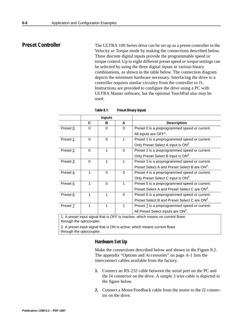
8-6 Application and Configuration Examples
nd in
nec-
8Application and Configuration Examples
Preset Controller The ULTRA 100 Series drive can be set up as a preset controller in the Velocity or Torque mode by making the connections described below. Three discrete digital inputs provide the programmable speed or torque control. Up to eight different preset speed or torque settings can be selected by using the three digital inputs in various binary combinations, as shown in the table below. The connection diagram depicts the minimum hardware necessary. Interfacing the drive to a controller requires similar circuitry from the controller to J1. Instructions are provided to configure the drive using a PC with ULTRA Master software, but the optional TouchPad also may be used.
Hardware Set Up
Make the connections described below and shown in the Figure 8.2. The appendix “Options and Accessories” on page A-1 lists the interconnect cables available from the factory.
1. Connect an RS-232 cable between the serial port on the PC athe J4 connector on the drive. A simple 3 wire cable is depictedthe figure below.
2. Connect a Motor/Feedback cable from the motor to the J2 contor on the drive.
Table 8.1: Preset Binary Inputs
InputsC B A Description
Preset 0 0 0 0 Preset 0 is a preprogrammed speed or current.
All inputs are OFF1.
Preset 1 0 0 1 Preset 1 is a preprogrammed speed or current.
Only Preset Select A input is ON2.
Preset 2 0 1 0 Preset 2 is a preprogrammed speed or current.
Only Preset Select B input is ON2.
Preset 3 0 1 1 Preset 3 is a preprogrammed speed or current.
Preset Select A and Preset Select B are ON2.
Preset 4 1 0 0 Preset 4 is a preprogrammed speed or current.
Only Preset Select C input is ON2.
Preset 5 1 0 1 Preset 5 is a preprogrammed speed or current.
Preset Select A and Preset Select C are ON2.
Preset 6 1 1 0 Preset 6 is a preprogrammed speed or current.
Preset Select B and Preset Select C are ON2.
Preset 7 1 1 1 Preset 7 is a preprogrammed speed or current.
All Preset Select inputs are ON2.
1. A preset input signal that is OFF is inactive, which means no current flows through the optocoupler.
2. A preset input signal that is ON is active, which means current flows through the optocoupler.
Publication 1398-5.2 – PDF 1997
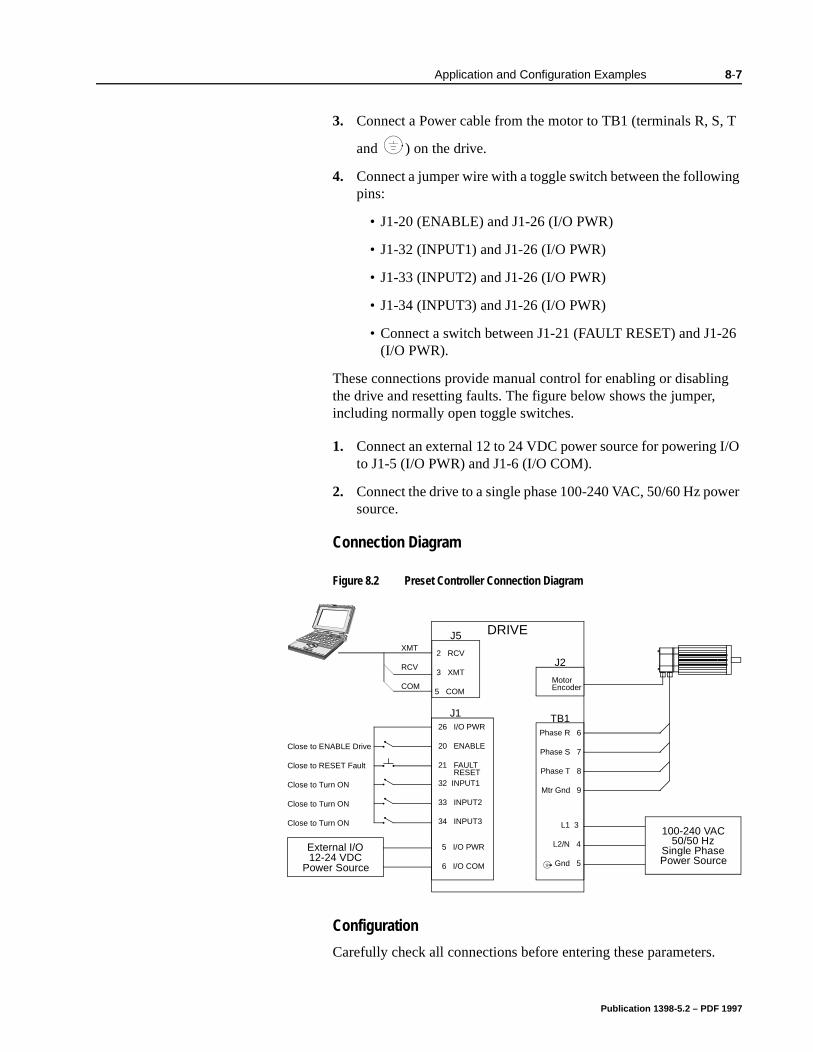
Application and Configuration Examples 8-7
26
g
I/O
wer
3. Connect a Power cable from the motor to TB1 (terminals R, S, T
and ) on the drive.
4. Connect a jumper wire with a toggle switch between the following pins:
• J1-20 (ENABLE) and J1-26 (I/O PWR)
• J1-32 (INPUT1) and J1-26 (I/O PWR)
• J1-33 (INPUT2) and J1-26 (I/O PWR)
• J1-34 (INPUT3) and J1-26 (I/O PWR)
• Connect a switch between J1-21 (FAULT RESET) and J1-(I/O PWR).
These connections provide manual control for enabling or disablinthe drive and resetting faults. The figure below shows the jumper, including normally open toggle switches.
1. Connect an external 12 to 24 VDC power source for powering to J1-5 (I/O PWR) and J1-6 (I/O COM).
2. Connect the drive to a single phase 100-240 VAC, 50/60 Hz posource.
Connection Diagram
Configuration
Carefully check all connections before entering these parameters.
Figure 8.2 Preset Controller Connection Diagram
J126 I/O PWR
20 ENABLE
21 FAULT
32 INPUT1
33 INPUT2
Close to ENABLE Drive
Close to RESET Fault
34 INPUT3
Close to Turn ON
Close to Turn ON
Close to Turn ON
DRIVE
L1 3
L2/N 4
Gnd 5
100-240 VAC50/50 Hz
Single PhasePower Source
J5
2 RCV
3 XMT
5 COM
XMT
RCV
COM
RESET
TB1Phase R 6
Phase S 7
Phase T 8
Mtr Gnd 9
J2
MotorEncoder
External I/O12-24 VDC
Power Source
5 I/O PWR
6 I/O COM
Publication 1398-5.2 – PDF 1997
8-8 Application and Configuration Examples
-1
-
of
ow
e
-8
t is
lect
e r
1. Switch the AC Power to ON and verify:
• Status LED is green. Refer to “Status Indicator” on page 10for an explanation of the display codes.
2. Start ULTRA Master on the PC.
3. Choose Cancel from the Drive Select dialog box.
4. Select PC Set Up from the Communications menu in ULTRA Master to display the personal computer’s communication settings
5. Verify the communications port settings of the PC match thosethe drive.
• If the settings are correct, select OK in the Port - Settings dia-log box.
• If the settings are different, correct the Port - Settings to allcommunications with the drive.
Factory default communications Port - Settings for the drivare:
– Baud Rate: 9600– Data Bits: 8– Parity: None– Stop Bits: 1– Serial Port: COM1
Refer to the section “RS-232 Communication Test” on page 11for troubleshooting instructions.
6. Select Read Drive Parameters from the Communications menu.
7. Verify the Drive Name and Address are correct for the drive thabeing addressed.
8. Choose OK to load the drive parameters.
9. If the message box appears that a motor must be selected, seOK. The Drive Setup window is displayed with Motor Model selection parameter active. The motor may be selected from thdrop down box. If this message box does not appear, the motodisplayed in the Motor Model box was previously selected.
10. Select or verify the correct motor model number from the dropdown Motor Model list.
11. If a message advises that the drive must be reset, choose Yes,
Note: A motor must be selected for the parameters to load.
Publication 1398-5.2 – PDF 1997

Application and Configuration Examples 8-9
or
12. Select the Operation Mode parameter for the drive:
13. Choose Close from the Drive Setup window.
14. Choose the Drive Parameters command icon from the Drive window and then select the Preset tab.
15. Enter the appropriate parameters for the Command mode in which the drive will operate:
Up to eight presets (0-7) may be programmed.
16. Choose Close to exit the Drive Parameters window.
17. Verify the Status indicator is green.
18. Select the I/O Configuration command icon from the Drive win-dow.
19. Assign one of the three Preset Selects (A, B and C) to each of the Digital Input Assignments. For example, the following selects three presets:
• Input 1 to Preset Select A
• Input 2 to Preset Select B
• Input 3 to Preset Select C
The presets provide up to eight binary combinations of speed current. Unassigned preset inputs should be set to Not Assigned, which forces an OFF state.
20. Verify all Digital Output Assignments are Not Assigned.
21. Choose Close to exit the I/O Configuration window.
Tuning
Velocity Mode Settings Torque Mode SettingsPreset Velocities as the Operation Mode
Preset Torques as the Operation Mode
Velocity Mode Settings Torque Mode SettingsEnter the appropriate velocity value for each speed required
Enter the appropriate cur-rent value for each torque required
Note: Do not attempt to Tune a drive with the Command mode set for Preset Torques. If the drive is set to Torque mode, continue with the Operation section below.
Do not attempt to Auto Tune systems that have gravitational effects. The ULTRA 100 Series will not hold initial position.
Publication 1398-5.2 – PDF 1997
8-10 Application and Configuration Examples
e
.
or.
e ters
1. Choose the Tuning command icon from the Drive window. The drive must be configured in Velocity mode for tuning to be effec-tive.
2. Select AutoTune from the Tuning mode group.
3. Select the appropriate values for the following Auto Tune com-mands:
• Distance and
• Step Current.
4. Select the appropriate entry for the Motor Direction:
• BiDirectional,
• Forward Only or
• Reverse Only.
5. Close the toggle switch between J1-26 and J1-20 to enable thdrive.
6. Choose Start from the Tuning window. The drive powers the motor shaft for a short period and then motion will cease. ThenULTRA Master displays the calculated gains and disables the drive.
7. Choose Normal Drive Operation from the Tuning window.
8. Open the switch between J1-26 and J1-20 to disable the drive
9. Choose Close to exit the Tuning window.
10. Verify the Status indicator is green.
11. Close any open windows or dialog boxes.
Operation
The drive is now configured as a Preset Controller in Velocity or Torque mode.
The servo parameters have been setup with the unloaded mot
The motor speed or current is controlled through the digital inputs.
The firmware saves the parameters in EEPROM memory. Thus thdrive can be power cycled and, after power-up, will use the parameselected in the steps above.
!
Intro
ATTENTION: Rotating motor shafts can cause extensive damage and injury. Motors must be properly guarded dur-ing testing and installation.
Publication 1398-5.2 – PDF 1997

Application and Configuration Examples 8-11
When motion is required:
1. Close the switch between J1-26 and J1-20 to enable the drive.
2. Close any of the switches for INPUT1, INPUT2 or INPUT3 to run the drive at the programmed preset speed or torque.
Publication 1398-5.2 – PDF 1997
8-12 Application and Configuration Examples
nd ble
nec-
, T
am.
s
I/O
wer
8Application and Configuration Examples
Position Follower (Master Encoder)
The ULTRA 100 Series can be electronically geared to a master incremental encoder generating quadrature encoder signals by making the hardware connections and performing the software setup and tuning described below. The connection diagram depicts the minimum hardware necessary. Interfacing the drive to an external controller requires similar circuitry from the controller to J1. Instructions are provided to configure the drive using a PC with ULTRA Master software, but the optional TouchPad also may be used.
Hardware Set Up
Make the connections described below and shown in the Figure 8.3. The appendix “Options and Accessories” on page A-1 lists the interconnect cables available from the factory.
1. Connect an RS-232 cable between the serial port on the PC athe J4 connector on the ULTRA 100 Series. A simple 3 wire cais depicted in the figure below.
2. Connect a Motor/Feedback cable from the motor to the J2 contor on the drive.
3. Connect a Power cable from the motor to TB1 (terminals R, S
and ) on the drive.
4. Connect the Master Encoder to the drive as shown in the diagr
5. Connect a jumper wire with a switches between the following pins:
• J1-20 (ENABLE) and J1-26 (I/O PWR)
• J1-32 (INPUT1) and J1-26 (I/O PWR)
• J1-21 (FAULT RESET) and J1-26 (I/O PWR).
These connections provide manual control for enabling or disabling the drive and resetting faults. The figure below showthe jumper, including normally open toggle switches.
6. Connect an external 12 to 24 VDC power source for powering to J1-5 (I/O PWR) and J1-6 (I/O COM).
7. Connect the drive to a single phase 100-240 VAC, 50/60 Hz posource.
Publication 1398-5.2 – PDF 1997
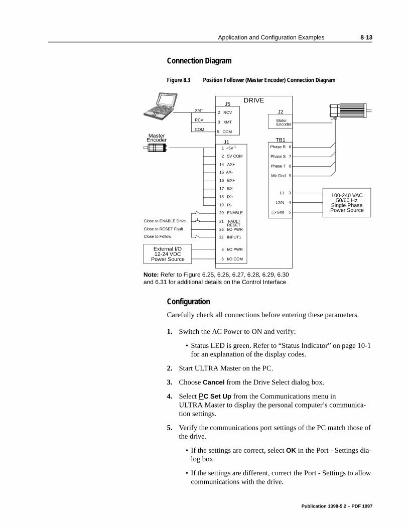
Application and Configuration Examples 8-13
-1
-
of
ow
Connection Diagram
Configuration
Carefully check all connections before entering these parameters.
1. Switch the AC Power to ON and verify:
• Status LED is green. Refer to “Status Indicator” on page 10for an explanation of the display codes.
2. Start ULTRA Master on the PC.
3. Choose Cancel from the Drive Select dialog box.
4. Select PC Set Up from the Communications menu in ULTRA Master to display the personal computer’s communication settings.
5. Verify the communications port settings of the PC match thosethe drive.
• If the settings are correct, select OK in the Port - Settings dia-log box.
• If the settings are different, correct the Port - Settings to allcommunications with the drive.
Figure 8.3 Position Follower (Master Encoder) Connection Diagram
J1 1 +5V 1
2 5V COM
14 AX+
15 AX-
16 BX+
Close to ENABLE Drive
Close to RESET Fault
17 BX-
Close to Follow
18 IX+
19 IX-
20 ENABLE
21 FAULT
32 INPUT1
MasterEncoder
Note: Refer to Figure 6.25, 6.26, 6.27, 6.28, 6.29, 6.30 and 6.31 for additional details on the Control Interface
J5DRIVE
2 RCV
3 XMT
5 COM
L1 3
L2/N 4
Gnd 5
XMT
RCV
COM
100-240 VAC50/60 Hz
Single PhasePower Source
RESET
TB1Phase R 6
Phase S 7
Phase T 8
Mtr Gnd 9
J2
MotorEncoder
External I/O12-24 VDC
Power Source
5 I/O PWR
6 I/O COM
26 I/O PWR
Publication 1398-5.2 – PDF 1997
8-14 Application and Configuration Examples
t is
lect
e r
). If
Factory default communications Port - Settings for the drive are:
– Baud Rate: 9600– Data Bits: 8– Parity: None– Stop Bits: 1– Serial Port: COM1
Refer to “RS-232 Communication Test” on page 11-8 for troubleshooting instructions.
6. Select Read Drive Parameters from the Communications menu.
7. Verify the Drive Name and Address are correct for the drive thabeing addressed.
8. Choose OK to load the drive parameters.
9. If the message box appears that a motor must be selected, seOK. The Drive Setup window is displayed with Motor Model selection parameter active. The motor may be selected from thdrop down box. If this message box does not appear, the motodisplayed in the Motor Model box was previously selected.
10. Select or verify the correct motor model number from the dropdown Motor Model list.
11. If a message advises that the drive must be reset, choose Yes,
12. Select Follower: Master Encoder as the Operation Mode for thedrive.
13. Choose Close from the Drive Setup window.
14. Choose the Drive Parameter command icon from the Drive win-dow, and then select the Follower tab.
15. Enter an appropriate Gear Ratio as the Follower Input. The default Gear Ratio is 1:1 (motor encoder pulses:master pulsesa Gear Ratio of 3:1 is entered, the motor is moved 3 encoder pulses for every incoming master pulse.
16. Choose Close to exit the Drive Parameters window.
17. Verify the Status indicator is green.
18. Select the I/O Configuration command icon from the Drive Win-dow.
Note: A motor must be selected for the parameters to load.
Publication 1398-5.2 – PDF 1997

Application and Configuration Examples 8-15
19. Select an appropriate digital input from the pull-down lists avail-able as Digital Input Assignments in the I/O Configuration win-dow.For example:
• Follower Enable as Input 1
• Not Assigned as Inputs 2 through 3.
• Not Assigned as Inputs 1 and 2.
20. Choose Close to exit the I/O Configuration window.
21. Verify the Status indicator is green.
Publication 1398-5.2 – PDF 1997
8-16 Application and Configuration Examples
e
.
r).
tor.
or.
Tuning
1. Choose the Tuning command icon from the Drive window.
2. Select AutoTune from the Tuning mode group.
3. Select the appropriate values for the following Auto Tune com-mands:
• Distance and
• Step Current.
4. Select the appropriate entry for the Motor Direction:
• BiDirectional,
• Forward Only or
• Reverse Only.
5. Close the toggle switch between J1-26 and J1-20 to enable thdrive.
6. Choose Start from the Tuning window. The drive powers the motor shaft for a short period and then motion will cease. ThenULTRA Master displays the calculated gains and disables the drive.
7. Choose Normal Drive Operation from the Tuning window.
8. Open the switch between J1-26 and J1-20 to disable the drive
9. Choose Close to exit the Tuning window.
10. Verify the Status indicator is green.
11. Close any open windows or dialog boxes.
Operation
The drive is now configured as a Position Follower (Master Encode
The current loop is compensated properly for the selected mo
The servo parameters have been setup with the unloaded mot
The motor position is controlled by the master encoder input.
Note: Do not attempt to Auto Tune systems that have gravitational effects. The ULTRA 100 Series will not hold initial position.
!
Intro
ATTENTION: Rotating motor shafts can cause extensive damage and injury. Motors must be properly guarded dur-ing testing and installation.
Publication 1398-5.2 – PDF 1997

Application and Configuration Examples 8-17
The firmware saves the parameters in EEPROM memory. Thus the drive can be power cycled and, after power-up, will use the parameters selected in the steps above.
When motion is required:
1. Close the switch between J1-26 and J1-20 to enable the drive.
2. Close the switch between J1-26 and J1-32 to enable following.
Publication 1398-5.2 – PDF 1997
8-18 Application and Configuration Examples
nd in
nec-
, T
I/O
wer
8Application and Configuration Examples
Position Follower (Step/Direction)
The ULTRA 100 Series drive can be set up as a Position Follower using Step/Direction commands by making the hardware connections and performing the software setup and tuning described below. This configuration allows the ULTRA 100 Series drive to electronically gear or drive a servo motor using step and direction signals that typically control a stepper drive. The connection diagram depicts the minimum hardware necessary. Interfacing the drive to a stepper indexer requires similar circuitry from the stepper indexer to J1. Instructions are provided to configure the drive using a PC with ULTRA Master software, but the optional TouchPad may also may be used.
Hardware Set Up
Make the connections described below and shown in the Figure 8.4. The appendix “Options and Accessories” on page A-1 lists the interconnect cables available from the factory.
1. Connect an RS-232 cable between the serial port on the PC athe J4 connector on the drive. A simple 3 wire cable is depictedthe figure below.
2. Connect a Motor/Feedback cable from the motor to the J2 contor on the drive.
3. Connect a Power cable from the motor to TB1 (terminals R, S
and ) on the drive.
4. Connect the Step/Direction signals to the drive as shown in thediagram.
5. Connect a jumper wire with a switches between the following pins:
• J1-20 (ENABLE) and J1-26 (I/O PWR)
• J1-32 (INPUT1) and J1-26 (I/O PWR)
• J1-21 (FAULT RESET) and J1-26 (I/O PWR).
8These connections provide manual control for enabling or disabling the drive and resetting faults. Figure 8.4 shows the jumper, including normally open toggle switches.
6. Connect an external 12 to 24 VDC power source for powering to J1-5 (I/O PWR) and J1-6 (I/O COM).
7. Connect the drive to a single phase 100-240 VAC, 50/60 Hz posource.
Publication 1398-5.2 – PDF 1997
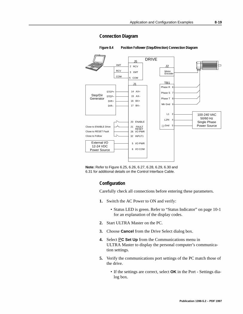
Application and Configuration Examples 8-19
-1
-
of
Connection Diagram
Configuration
Carefully check all connections before entering these parameters.
1. Switch the AC Power to ON and verify:
• Status LED is green. Refer to “Status Indicator” on page 10for an explanation of the display codes.
2. Start ULTRA Master on the PC.
3. Choose Cancel from the Drive Select dialog box.
4. Select PC Set Up from the Communications menu in ULTRA Master to display the personal computer’s communication settings.
5. Verify the communications port settings of the PC match thosethe drive.
• If the settings are correct, select OK in the Port - Settings dia-log box.
Figure 8.4 Position Follower (Step/Direction) Connection Diagram
J1
Close to ENABLE Drive
Close to RESET Fault
Close to Follow
20 ENABLE
21 FAULT
26 I/O PWR
32 INPUT1
Note: Refer to Figure 6.25, 6.26, 6.27, 6.28, 6.29, 6.30 and 6.31 for additional details on the Control Interface Cable.
J5DRIVE
2 RCV
3 XMT
5 COM
L1 3
L2/N 4
Gnd 5
XMT
RCV
COM
100-240 VAC50/60 Hz
Single PhasePower Source
RESET
TB1Phase R 6
Phase S 7
Phase T 8
Mtr Gnd 9
J2
MotorEncoder
5 I/O PWR
6 I/O COM
Step/DirGenerator
14 AX+STEP+
15 AX–STEP–
16 BX+DIR+
17 BX–DIR–
External I/O12-24 VDC
Power Source
Publication 1398-5.2 – PDF 1997
8-20 Application and Configuration Examples
ow
e
t is
lect
e r
). If
• If the settings are different, correct the Port - Settings to allcommunications with the drive.
Factory default communications Port - Settings for the drivare:
– Baud Rate: 9600– Data Bits: 8– Parity: None– Stop Bits: 1– Serial Port: COM1
Refer to “RS-232 Communication Test” on page 11-8 for troubleshooting instructions.
6. Select Read Drive Parameters from the Communications menu.
7. Verify the Drive Name and Address are correct for the drive thabeing addressed.
8. Choose OK to load the drive parameters.
9. If the message box appears that a motor must be selected, seOK. The Drive Setup window is displayed with Motor Model selection parameter active. The motor may be selected from thdrop down box. If this message box does not appear, the motodisplayed in the Motor Model box was previously selected.
10. Select or verify the correct motor model number from the dropdown Motor Model list.
11. If a message advises that the drive must be reset, choose Yes,
12. Select Follower: Step/Direction as the Operation Mode for the drive.
13. Choose Close to exit the Drive Set Up window.
14. Choose the Drive Parameters command icon from the Drive window and then select the Follower tab.
15. Enter an appropriate Gear Ratio as the Follower Input. The default Gear Ratio is 1:1 (motor encoder pulses:master pulsesa Gear Ratio of 3:1 is entered, the motor is moved 3 encoder pulses for every incoming step pulse.
16. Choose Close to exit the Drive Parameters window.
17. Verify the Status indicator is green.
18. Select the I/O Configuration command icon from the Drive Win-dow.
Note: A motor must be selected for the parameters to load.
Publication 1398-5.2 – PDF 1997

Application and Configuration Examples 8-21
19. Select an appropriate digital input from the pull-down lists avail-able as Digital Input Assignments in the I/O Configuration win-dow.For example:
• Follower Enable as Input 1
• Not Assigned as Inputs 2 through 3.
• Not Assigned as Outputs 1 and 2.
20. Choose Close to exit the I/O Configuration window.
Publication 1398-5.2 – PDF 1997
8-22 Application and Configuration Examples
e
.
).
or.
Tuning
1. Choose the Tuning command icon from the Drive window.
2. Select AutoTune from the Tuning mode group.
3. Select the appropriate values for the following Auto Tune com-mands:
• Distance and
• Step Current.
4. Select the appropriate entry for the Motor Direction:
• BiDirectional,
• Forward Only or
• Reverse Only.
5. Close the toggle switch between J1-26 and J1-20 to enable thdrive.
6. Choose Start from the Tuning window. The drive powers the motor shaft for a short period and then motion will cease. ThenULTRA Master displays the calculated gains and disables the drive.
7. Choose Normal Drive Operation from the Tuning window.
8. Open the switch between J1-26 and J1-20 to disable the drive
9. Choose Close to exit the Tuning window.
10. Verify the Status indicator is green.
11. Close any open windows or dialog boxes.
Operation
The drive is now configured as a Position Follower (Step/Direction
The servo parameters have been setup with the unloaded mot
The motor position is controlled by the step/direction inputs.
Note: Do not attempt to Auto Tune systems that have gravitational effects. The ULTRA 100 Series will not hold initial position.
!
Intro
ATTENTION: Rotating motor shafts can cause extensive damage and injury. Motors must be properly guarded dur-ing testing and installation.
Publication 1398-5.2 – PDF 1997

Application and Configuration Examples 8-23
The firmware saves the parameters in EEPROM memory. Thus the drive can be power cycled and, after power-up, will use the parameters selected in the steps above.
When motion is required:
1. Close the switch between J1-26 and J1-20 to enable the drive.
2. Close the toggle switch between J1-26 and J1-32 to enable follow-ing.
Publication 1398-5.2 – PDF 1997
nd ble
nec-
, T
am.
ng
s
I/O
wer
8Application and Configuration Examples
Position Follower (Step Up/Down)
The ULTRA 100 Series can be set up as a Position Following using Step Up and Step Down signals typically used to control stepper drives. The connection diagram depicts the minimum hardware necessary. Interfacing the drive to a controller requires similar circuitry from the indexer to J1. Instructions are provided to configure the drive with ULTRA Master software.
Hardware Set Up
Make the connections described below and shown in the Figure 8.5. The appendix “Options and Accessories” on page A-1 lists the interconnect cables available from the factory.
1. Connect an RS-232 cable between the serial port on the PC athe J4 connector on the ULTRA 100 Series. A simple 3 wire cais depicted in the figure below.
2. Connect a Motor/Feedback cable from the motor to the J2 contor on the ULTRA 100 Series.
3. Connect a Power cable from the motor to TB1 (terminals R, S
and ) on the drive.
4. Connect the Stepper Indexer to the drive as shown in the diagr
5. Connect a jumper wire with a toggle switch between the followipins:
• J1-20 (ENABLE) and J1-26 (I/O PWR)
• J1-32 (INPUT1) and J1-26 (I/O PWR)
• J1-21 (FAULT RESET) and J1-26 (I/O PWR).
These connections provide manual control for enabling or disabling the drive and resetting faults. The figure below showthe jumper, including normally open toggle switches.
6. Connect an external 12 to 24 VDC power source for powering to J1-5 (I/O PWR) and J1-6 (I/O COM).
7. Connect the drive to a single phase 100-240 VAC, 50/60 Hz posource.
Publication 1398-5.2 – PDF 1997
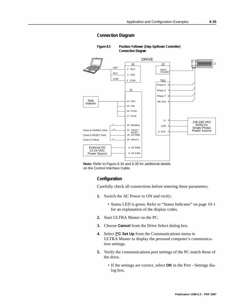
Application and Configuration Examples 8-25
-1
-
of
Connection Diagram
Configuration
Carefully check all connections before entering these parameters.
1. Switch the AC Power to ON and verify:
• Status LED is green. Refer to “Status Indicator” on page 10for an explanation of the display codes.
2. Start ULTRA Master on the PC.
3. Choose Cancel from the Drive Select dialog box.
4. Select PC Set Up from the Communications menu in ULTRA Master to display the personal computer’s communication settings.
5. Verify the communications port settings of the PC match thosethe drive.
• If the settings are correct, select OK in the Port - Settings dia-log box.
Figure 8.5 Position Follower (Step Up/Down Controller) Connection Diagram
J1
14 CW+
15 CW-
16 CCW+
Close to ENABLE Drive
Close to RESET Fault
17 CCW-
Close to Follow
21 FAULT
26 I/O PWR
32 INPUT1
20 ENABLE
StepIndexer
Note: Refer to Figure 6.34 and 6.35 for additional details on the Control Interface Cable.
DRIVE
L1 3
L2/N 4
Gnd 5
100-240 VAC50/50 Hz
Single PhasePower Source
RESET
TB1Phase R 6
Phase S 7
Phase T 8
Mtr Gnd 9
J2
MotorEncoder
External I/O12-24 VDC
Power Source
5 I/O PWR
6 I/O COM
J5
2 RCV
3 XMT
5 COM
XMT
RCV
COM
Publication 1398-5.2 – PDF 1997
8-26 Application and Configuration Examples
ow
e
t is
lect
e r
). If
• If the settings are different, correct the Port - Settings to allcommunications with the drive.
Factory default communications Port - Settings for the drivare:
– Baud Rate: 9600– Data Bits: 8– Parity: None– Stop Bits: 1– Serial Port: COM1
Refer to “RS-232 Communication Test” on page 11-8 for troubleshooting instructions.
6. Select Read Drive Parameters from the Communications menu.
7. Verify the Drive Name and Address are correct for the drive thabeing addressed.
8. Choose OK to load the drive parameters.
9. If the message box appears that a motor must be selected, seOK. The Drive Setup window is displayed with Motor Model selection parameter active. The motor may be selected from thdrop down box. If this message box does not appear, the motodisplayed in the Motor Model box was previously selected.
10. Select or verify the correct motor model number from the dropdown Motor Model list.
11. If a message advises that the drive must be reset, choose Yes,
12. Select Follower: Step Up/Step Down as the Operation Mode forthe drive.
13. Choose Close to exit the Drive Set Up window.
14. Choose the Drive Parameters command icon from the Drive window and then select the Follower tab.
15. Enter an appropriate Gear Ratio as the Follower Input. The default Gear Ratio is 1:1 (motor encoder pulses:master pulsesa Gear Ratio of 3:1 is entered, the motor is moved 3 encoder pulses for every incoming step pulse.
16. Choose Close to exit the Drive Parameters window.
17. Verify the Status indicator is green.
18. Select the I/O Configuration command icon from the Drive Win-dow.
Note: A motor must be selected for the parameters to load.
Publication 1398-5.2 – PDF 1997
Application and Configuration Examples 8-27
19. Select an appropriate digital input from the pull-down lists avail-able as Digital Input Assignments in the I/O Configuration win-dow.For example:
• Follower Enable as Input 1
• Not Assigned as Inputs 2 through 3.
• Not Assigned as Outputs 1 and 2.
20. Choose Close to exit the I/O Configuration window.
Publication 1398-5.2 – PDF 1997
8-28 Application and Configuration Examples
e
.
/
or.
Tuning
1. Choose the Tuning command icon from the Drive window.
2. Select AutoTune from the Tuning mode group.
3. Select the appropriate values for the following Auto Tune com-mands:
• Distance and
• Step Current.
4. Select the appropriate entry for the Motor Direction:
• BiDirectional,
• Forward Only or
• Reverse Only.
5. Close the toggle switch between J1-26 and J1-20 to enable thdrive.
6. Choose Start from the Tuning window. The drive powers the motor shaft for a short period and then motion will cease. ThenULTRA Master displays the calculated gains and disables the drive.
7. Choose Normal Drive Operation from the Tuning window.
8. Open the switch between J1-26 and J1-20 to disable the drive
9. Choose Close to exit the Tuning window.
10. Verify the Status indicator is green.
11. Close any open windows or dialog boxes.
Operation
The drive is now configured as either a Position Follower (Step UpStep Down).
The servo parameters have been setup with the unloaded mot
The motor position is controlled by the step indexer.
Note: Do not attempt to Auto Tune systems that have gravitational effects. The ULTRA 100 Series will not hold initial position.
!
Intro
ATTENTION: Rotating motor shafts can cause extensive damage and injury. Motors must be properly guarded dur-ing testing and installation.
Publication 1398-5.2 – PDF 1997

Application and Configuration Examples 8-29
The firmware saves the parameters in EEPROM memory. Thus the drive can be power cycled and, after power-up, will use the parameters selected in the steps above.
When motion is required:
1. Close the switch between J1-26 and J1-20 to enable the drive.
2. Close the toggle switch between J1-26 and J1-32 to enable follow-ing.
Publication 1398-5.2 – PDF 1997
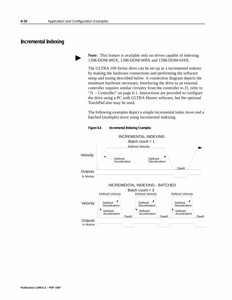
8-30 Application and Configuration Examples
re l
d a
8Application and Configuration Examples
Incremental Indexing
The ULTRA 100 Series drive can be set up as a incremental indexer by making the hardware connections and performing the software setup and tuning described below. A connection diagram depicts the minimum hardware necessary. Interfacing the drive to an external controller requires similar circuitry from the controller to J1, refer to “J1 – Controller” on page 6-1. Instructions are provided to configuthe drive using a PC with ULTRA Master software, but the optionaTouchPad also may be used.
The following examples depict a simple incremental index move anbatched (multiple) move using incremental indexing.
Note: This feature is available only on drives capable of indexing: 1398-DDM-005X, 1398-DDM-009X and 1398-DDM-019X.
Figure 8.6 Incremental Indexing Examples
Velocity
Dwell
DefinedDeceleration
DefinedAcceleration
Defined Velocity
Outputs
INCREMENTAL INDEXING
Velocity
Dwell
DefinedDeceleration
DefinedAcceleration
Defined Velocity
INCREMENTAL INDEXING - BATCHED
Dwell
DefinedDeceleration
DefinedAcceleration
Defined Velocity
Dwell
DefinedDeceleration
DefinedAcceleration
Defined VelocityBatch count = 3
Batch count = 1
In Motion
OutputsIn Motion
Publication 1398-5.2 – PDF 1997

Application and Configuration Examples 8-31
nd ble
nec-
, T
ng
s
I/O
wer
-1
-
Hardware Set Up
Make the connections described below and shown in the Figure 8.7. The appendix “Options and Accessories” on page A-1 lists the interconnect cables available from the factory.
1. Connect an RS-232 cable between the serial port on the PC athe J4 connector on the ULTRA 100 Series. A simple 3 wire cais depicted in the figure below.
2. Connect a Motor/Feedback cable from the motor to the J2 contor on the ULTRA 100 Series.
3. Connect a Power cable from the motor to TB1 (terminals R, S
and ) on the drive.
4. Connect a jumper wire with a toggle switch between the followipins:
• J1-20 (ENABLE) and J1-26 (I/O PWR)
• J1-32 (INPUT1) and J1-26 (I/O PWR)
• J1-21 (FAULT RESET) and J1-26 (I/O PWR).
These connections provide manual control for enabling or disabling the drive and resetting faults. The figure below showthe jumper, including normally open toggle switches.
5. Connect an external 12 to 24 VDC power source for powering to J1-5 (I/O PWR) and J1-6 (I/O COM).
6. Connect the drive to a single phase 100-240 VAC, 50/60 Hz posource.
Connection Diagram
Configuration
Carefully check all connections before entering these parameters.
1. Switch the AC Power to ON and verify:
• Status LED is green. Refer to “Status Indicator” on page 10for an explanation of the display codes.
2. Start ULTRA Master on the PC.
3. Choose Cancel from the Drive Select dialog box.
4. Select PC Set Up from the Communications menu in ULTRA Master to display the personal computer’s communication settings.
Publication 1398-5.2 – PDF 1997
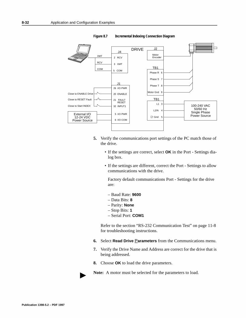
8-32 Application and Configuration Examples
ow
e
-8
t is
5. Verify the communications port settings of the PC match those of the drive.
• If the settings are correct, select OK in the Port - Settings dia-log box.
• If the settings are different, correct the Port - Settings to allcommunications with the drive.
Factory default communications Port - Settings for the drivare:
– Baud Rate: 9600– Data Bits: 8– Parity: None– Stop Bits: 1– Serial Port: COM1
Refer to the section “RS-232 Communication Test” on page 11for troubleshooting instructions.
6. Select Read Drive Parameters from the Communications menu.
7. Verify the Drive Name and Address are correct for the drive thabeing addressed.
8. Choose OK to load the drive parameters.
Figure 8.7 Incremental Indexing Connection Diagram
J126 I/O PWR
20 ENABLE
21 FAULT
32 INPUT1
Close to ENABLE Drive
Close to RESET Fault
J4DRIVE
TB1
2 RCV
3 XMT
5 COM
L1 3
L2/N 4
Gnd 5
XMT
RCV
COM
100-240 VAC50/60 Hz
Single PhasePower Source
TB1
Phase R 6
Phase S 7
Phase T 8
Motor Gnd 9
J2
MotorEncoder
RESET
Close to Start INDEX
External I/O12-24 VDC
Power Source
5 I/O PWR
6 I/O COM
Note: A motor must be selected for the parameters to load.
Publication 1398-5.2 – PDF 1997

Application and Configuration Examples 8-33
l-
9. If the message box appears that a motor must be selected, select OK. The Drive Setup window is displayed with Motor Model selection parameter active. The motor may be selected from the drop down box. If this message box does not appear, the motor displayed in the Motor Model box was previously selected.
10. Select or verify the correct motor model number from the drop down Motor Model list.
11. If a message advises that the drive must be reset, choose Yes.
12. Select Indexing as the Operation Mode for the drive.
13. Choose Close to exit the Drive Set Up window.
14. Choose the Drive Parameters command icon from the Drive window and then select the Indexing tab.
15. Enter the following values for Index 0. Refer to “Incremental Indexing Examples” on page 8-30 for examples of Single and Batched Incremental Indexing profiles.
16. Choose Close to exit the Drive Parameters window.
17. Verify the Status indicator is green.
18. Select the I/O Configuration command icon from the Drive Win-dow.
19. Select an appropriate digital input from the pull-down lists avaiable as Digital Input Assignments in the I/O Configuration win-dow.For example:
• Start Index as Input 1
• Not Assigned as Inputs 2 through 3.
Single Move Settings Batched Move SettingsIncremental as Mode Incremental as Mode8000 as Distance 8000 as Distance1 as the Batch Count 3 as the Batch Count
0 as Dwell 1000 as DwellAppropriate values for Acceleration and Decelera-tion
Appropriate values for Acceleration and Decelera-tion
Publication 1398-5.2 – PDF 1997

8-34 Application and Configuration Examples
• Not Assigned as Outputs 1 and 2.
20. Choose Close to exit the I/O Configuration window.
Publication 1398-5.2 – PDF 1997
Application and Configuration Examples 8-35
e
.
or.
Tuning
1. Choose the Tuning command icon from the Drive window.
2. Select AutoTune from the Tuning mode group.
3. Select the appropriate values for the following Auto Tune com-mands:
• Distance and
• Step Current.
4. Select the appropriate entry for the Motor Direction:
• BiDirectional,
• Forward Only or
• Reverse Only.
5. Close the toggle switch between J1-26 and J1-20 to enable thdrive.
6. Choose Start from the Tuning window. The drive powers the motor shaft for a short period and then motion will cease. ThenULTRA Master displays the calculated gains and disables the drive.
7. Choose Normal Drive Operation from the Tuning window.
8. Open the switch between J1-26 and J1-20 to disable the drive
9. Choose Close to exit the Tuning window.
10. Verify the Status indicator is green.
11. Close any open windows or dialog boxes.
Operation
The drive is now configured as an Incremental Indexing controller.
The servo parameters have been setup with the unloaded mot
Motion is commanded through the inputs.
Note: Do not attempt to Auto Tune systems that have gravitational effects. The ULTRA 100 Series will not hold initial position.
!
Intro
ATTENTION: Rotating motor shafts can cause extensive damage and injury. Motors must be properly guarded dur-ing testing and installation.
Publication 1398-5.2 – PDF 1997
8-36 Application and Configuration Examples
The firmware saves the parameters in EEPROM memory. Thus the drive can be power cycled and, after power-up, will use the parameters selected in the steps above.
When motion is required:
1. Close the switch between J1-26 and J1-20 to enable the drive.
2. Close the toggle switch between J1-26 and J1-32 to start Index 0.
Publication 1398-5.2 – PDF 1997
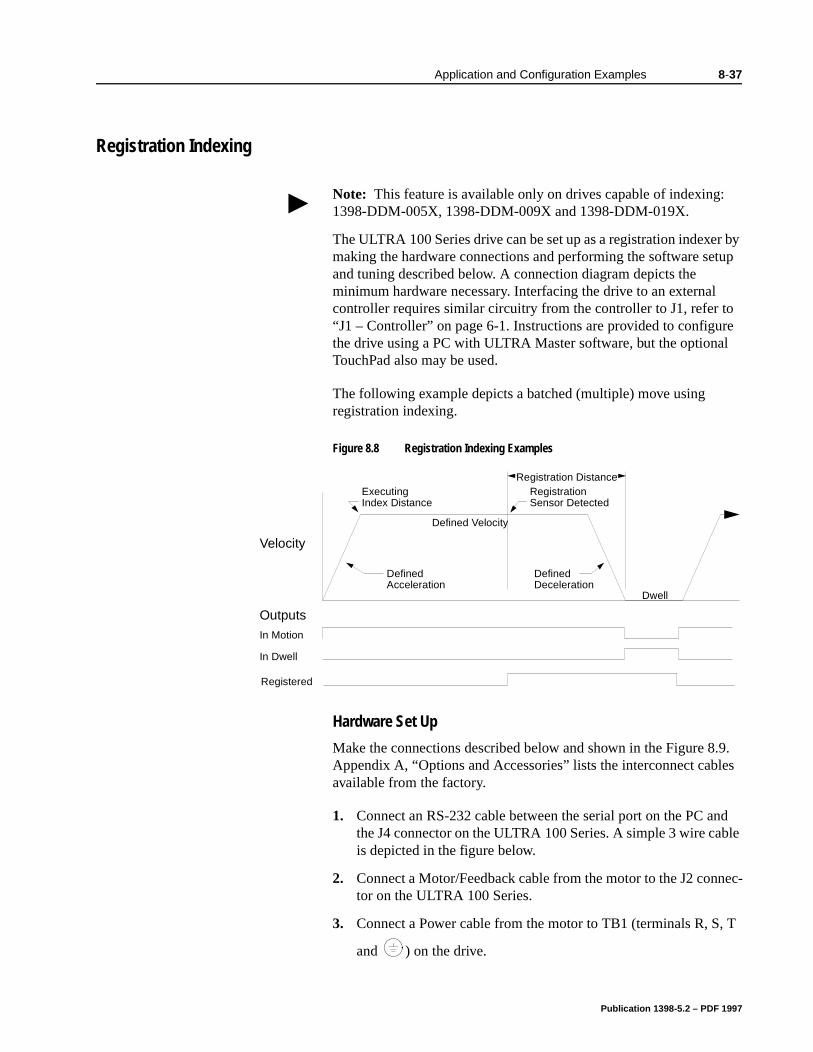
Application and Configuration Examples 8-37
re l
.9. es
nd ble
nec-
, T
8Application and Configuration Examples
Registration Indexing
The ULTRA 100 Series drive can be set up as a registration indexer by making the hardware connections and performing the software setup and tuning described below. A connection diagram depicts the minimum hardware necessary. Interfacing the drive to an external controller requires similar circuitry from the controller to J1, refer to “J1 – Controller” on page 6-1. Instructions are provided to configuthe drive using a PC with ULTRA Master software, but the optionaTouchPad also may be used.
The following example depicts a batched (multiple) move using registration indexing.
Hardware Set Up
Make the connections described below and shown in the Figure 8Appendix A, “Options and Accessories” lists the interconnect cablavailable from the factory.
1. Connect an RS-232 cable between the serial port on the PC athe J4 connector on the ULTRA 100 Series. A simple 3 wire cais depicted in the figure below.
2. Connect a Motor/Feedback cable from the motor to the J2 contor on the ULTRA 100 Series.
3. Connect a Power cable from the motor to TB1 (terminals R, S
and ) on the drive.
Note: This feature is available only on drives capable of indexing: 1398-DDM-005X, 1398-DDM-009X and 1398-DDM-019X.
Figure 8.8 Registration Indexing Examples
Velocity
Registration Distance
Dwell
DefinedDeceleration
DefinedAcceleration
Defined Velocity
ExecutingIndex Distance
RegistrationSensor Detected
OutputsIn Motion
In Dwell
Registered
Publication 1398-5.2 – PDF 1997
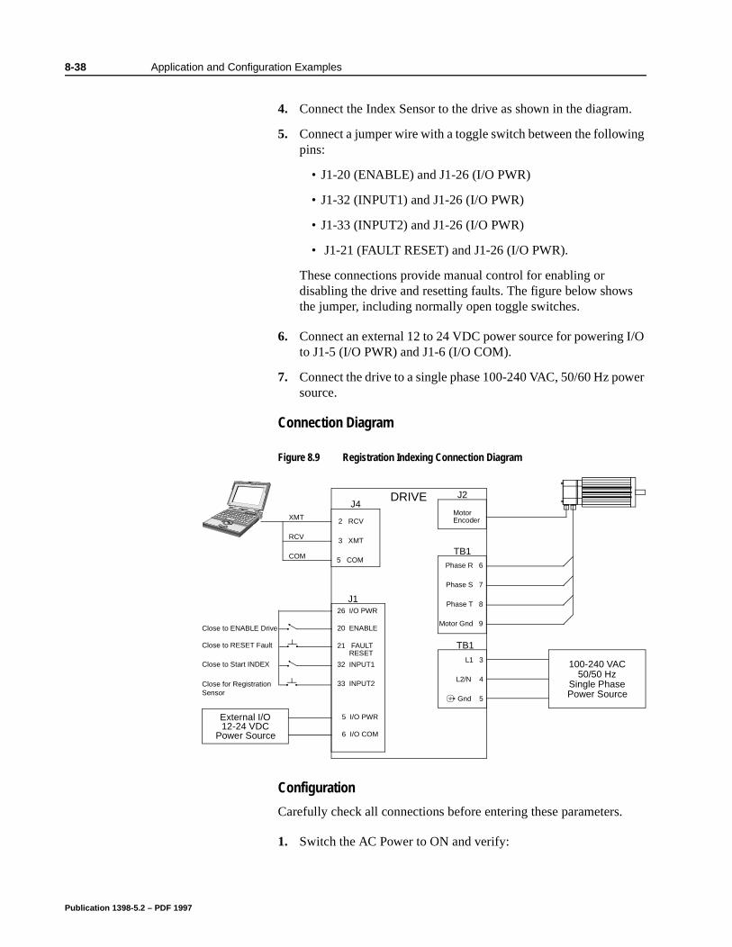
8-38 Application and Configuration Examples
s
I/O
wer
4. Connect the Index Sensor to the drive as shown in the diagram.
5. Connect a jumper wire with a toggle switch between the following pins:
• J1-20 (ENABLE) and J1-26 (I/O PWR)
• J1-32 (INPUT1) and J1-26 (I/O PWR)
• J1-33 (INPUT2) and J1-26 (I/O PWR)
• J1-21 (FAULT RESET) and J1-26 (I/O PWR).
These connections provide manual control for enabling or disabling the drive and resetting faults. The figure below showthe jumper, including normally open toggle switches.
6. Connect an external 12 to 24 VDC power source for powering to J1-5 (I/O PWR) and J1-6 (I/O COM).
7. Connect the drive to a single phase 100-240 VAC, 50/60 Hz posource.
Connection Diagram
Configuration
Carefully check all connections before entering these parameters.
1. Switch the AC Power to ON and verify:
Figure 8.9 Registration Indexing Connection Diagram
J126 I/O PWR
20 ENABLE
21 FAULT
32 INPUT1
Close to ENABLE Drive
Close to RESET Fault
J4DRIVE
TB1
2 RCV
3 XMT
5 COM
L1 3
L2/N 4
Gnd 5
XMT
RCV
COM
100-240 VAC50/50 Hz
Single PhasePower Source
TB1Phase R 6
Phase S 7
Phase T 8
Motor Gnd 9
J2
MotorEncoder
RESET
Close to Start INDEX
Close for RegistrationSensor
33 INPUT2
External I/O12-24 VDC
Power Source
5 I/O PWR
6 I/O COM
Publication 1398-5.2 – PDF 1997
Application and Configuration Examples 8-39
-1
-
of
ow
e
t is
lect
e r
• Status LED is green. Refer to “Status Indicator” on page 10for an explanation of the display codes.
2. Start ULTRA Master on the PC.
3. Choose Cancel from the Drive Select dialog box.
4. Select PC Set Up from the Communications menu in ULTRA Master to display the personal computer’s communication settings.
5. Verify the communications port settings of the PC match thosethe drive.
• If the settings are correct, select OK in the Port - Settings dia-log box.
• If the settings are different, correct the Port - Settings to allcommunications with the drive.
Factory default communications Port - Settings for the drivare:
– Baud Rate: 9600– Data Bits: 8– Parity: None– Stop Bits: 1– Serial Port: COM1
Refer to “RS-232 Communication Test” on page 11-8 for troubleshooting instructions.
6. Select Read Drive Parameters from the Communications menu.
7. Verify the Drive Name and Address are correct for the drive thabeing addressed.
8. Choose OK to load the drive parameters.
9. If the message box appears that a motor must be selected, seOK. The Drive Setup window is displayed with Motor Model selection parameter active. The motor may be selected from thdrop down box. If this message box does not appear, the motodisplayed in the Motor Model box was previously selected.
10. Select or verify the correct motor model number from the dropdown Motor Model list.
11. If a message advises that the drive must be reset, choose Yes.
12. Select Indexing as the Operation Mode for the drive.
Note: A motor must be selected for the parameters to load.
Publication 1398-5.2 – PDF 1997
8-40 Application and Configuration Examples
13. Choose Close to exit the Drive Set Up window.
14. Choose the Drive Parameters command icon from the Drive window and then select the Indexing tab.
15. Enter the following values for Index 0.
16. Choose Close to exit the Drive Parameters window.
17. Verify the Status indicator is green.
18. Select the I/O Configuration command icon from the Drive Win-dow.
19. Select an appropriate digital input from the pull-down lists avail-able as Digital Input Assignments in the I/O Configuration win-dow.For example:
• Start Index as Input 1
• Registration Sensor as Input 2.
• Not Assigned as Input 3.
• Not Assigned as Outputs 1 and 2.
20. Choose Close to exit the I/O Configuration window.
Single Move Settings Batched Move SettingsRegistration as Mode Registration as Mode8000 as Distance 8000 as Distance
8000 as Registration Dis-tance
1 as the Batch Count 3 as the Batch Count
0 as Dwell 1000 as DwellAppropriate values for Acceleration and Decelera-tion
Appropriate values for Acceleration and Decelera-tion
Note: The Registration Distance must be longer than the Deceleration Distance or the move will not be registered.
Publication 1398-5.2 – PDF 1997

Application and Configuration Examples 8-41
e
.
or.
Tuning
1. Choose the Tuning command icon from the Drive window.
2. Select AutoTune from the Tuning mode group.
3. Select the appropriate values for the following Auto Tune com-mands:
• Distance and
• Step Current.
4. Select the appropriate entry for the Motor Direction:
• BiDirectional,
• Forward Only or
• Reverse Only.
5. Close the toggle switch between J1-26 and J1-20 to enable thdrive.
6. Choose Start from the Tuning window. The drive powers the motor shaft for a short period and then motion will cease. ThenULTRA Master displays the calculated gains and disables the drive.
7. Choose Normal Drive Operation from the Tuning window.
8. Open the switch between J1-26 and J1-20 to disable the drive
9. Choose Close to exit the Tuning window.
10. Verify the Status indicator is green.
11. Close any open windows or dialog boxes.
Operation
The drive is now configured as a Registration Indexing controller.
The servo parameters have been setup with the unloaded mot
Motion is commanded through the inputs.
Note: Do not attempt to Auto Tune systems that have gravitational effects. The ULTRA 100 Series will not hold initial position.
!
Intro
ATTENTION: Rotating motor shafts can cause extensive damage and injury. Motors must be properly guarded dur-ing testing and installation.
Publication 1398-5.2 – PDF 1997
8-42 Application and Configuration Examples
The firmware saves the parameters in EEPROM memory. Thus the drive can be power cycled and, after power-up, will use the parameters selected in the steps above.
When motion is required:
1. Close the switch between J1-26 and J1-20 to enable the drive.
2. Close the toggle switch between J1-26 and J1-32 to start Index 0.
3. Close the toggle switch between J1-26 and J1-33 to simulate reg-istration.
Publication 1398-5.2 – PDF 1997
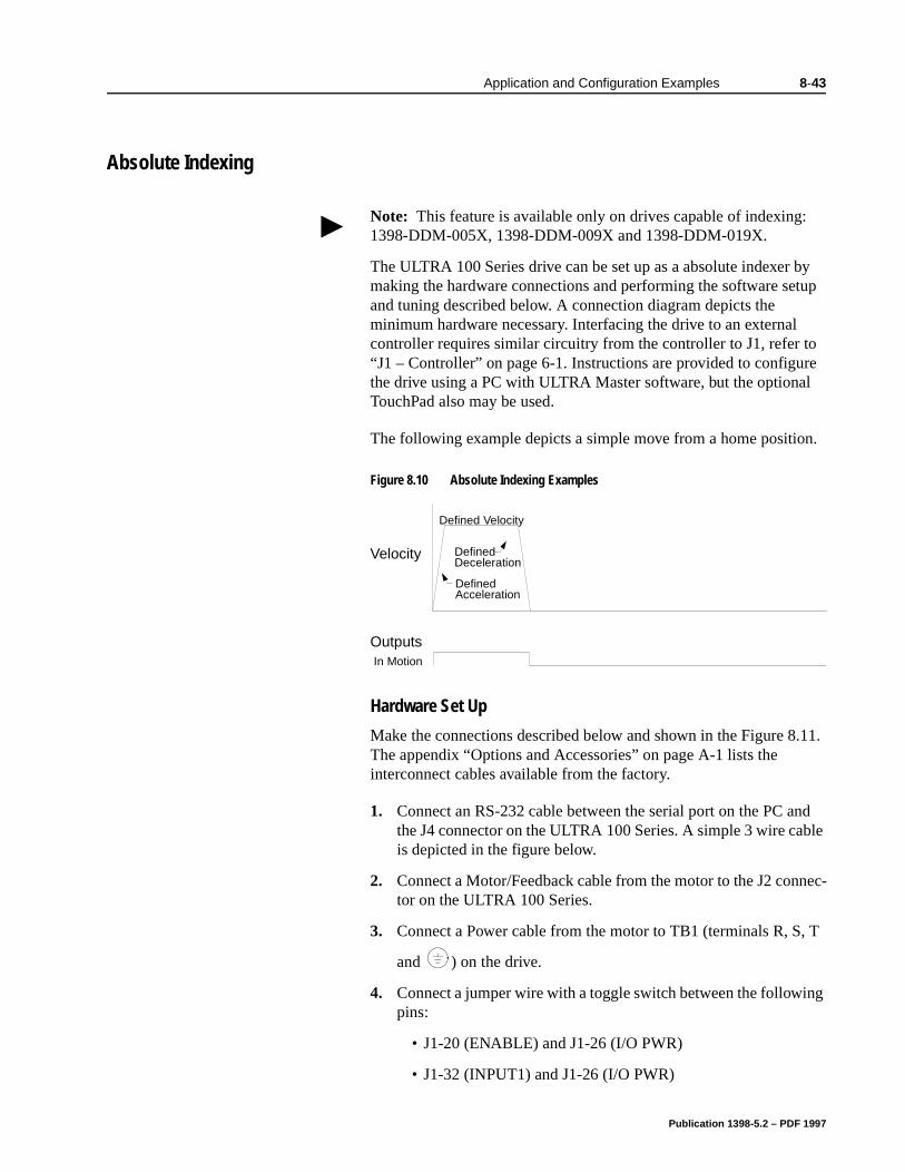
Application and Configuration Examples 8-43
re l
n.
.11.
nd ble
nec-
, T
ng
8Application and Configuration Examples
Absolute Indexing
The ULTRA 100 Series drive can be set up as a absolute indexer by making the hardware connections and performing the software setup and tuning described below. A connection diagram depicts the minimum hardware necessary. Interfacing the drive to an external controller requires similar circuitry from the controller to J1, refer to “J1 – Controller” on page 6-1. Instructions are provided to configuthe drive using a PC with ULTRA Master software, but the optionaTouchPad also may be used.
The following example depicts a simple move from a home positio
Hardware Set Up
Make the connections described below and shown in the Figure 8The appendix “Options and Accessories” on page A-1 lists the interconnect cables available from the factory.
1. Connect an RS-232 cable between the serial port on the PC athe J4 connector on the ULTRA 100 Series. A simple 3 wire cais depicted in the figure below.
2. Connect a Motor/Feedback cable from the motor to the J2 contor on the ULTRA 100 Series.
3. Connect a Power cable from the motor to TB1 (terminals R, S
and ) on the drive.
4. Connect a jumper wire with a toggle switch between the followipins:
• J1-20 (ENABLE) and J1-26 (I/O PWR)
• J1-32 (INPUT1) and J1-26 (I/O PWR)
Note: This feature is available only on drives capable of indexing: 1398-DDM-005X, 1398-DDM-009X and 1398-DDM-019X.
Figure 8.10 Absolute Indexing Examples
Velocity DefinedDeceleration
DefinedAcceleration
Defined Velocity
OutputsIn Motion
Publication 1398-5.2 – PDF 1997
8-44 Application and Configuration Examples
s
I/O
wer
• J1-33 (INPUT2) and J1-26 (I/O PWR)
• J1-21 (FAULT RESET) and J1-26 (I/O PWR).
These connections provide manual control for enabling or disabling the drive and resetting faults. The figure below showthe jumper, including normally open toggle switches.
5. Connect an external 12 to 24 VDC power source for powering to J1-5 (I/O PWR) and J1-6 (I/O COM).
6. Connect the drive to a single phase 100-240 VAC, 50/60 Hz posource.
Publication 1398-5.2 – PDF 1997
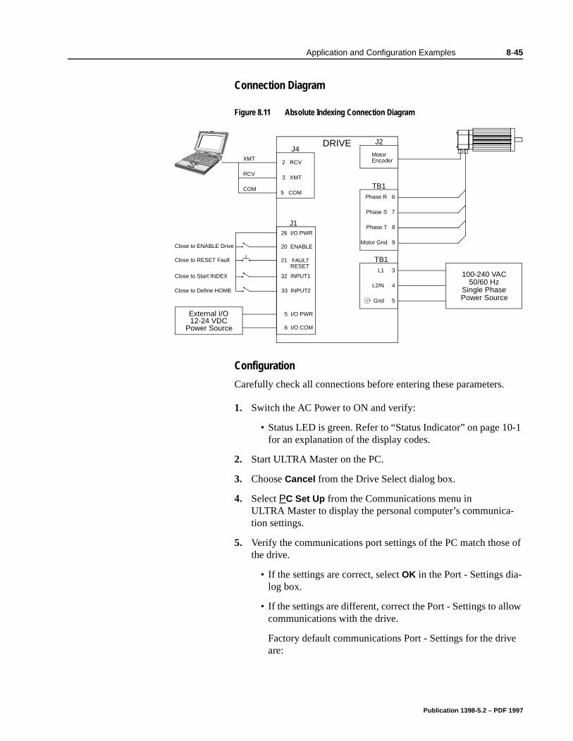
Application and Configuration Examples 8-45
-1
-
of
ow
e
Connection Diagram
Configuration
Carefully check all connections before entering these parameters.
1. Switch the AC Power to ON and verify:
• Status LED is green. Refer to “Status Indicator” on page 10for an explanation of the display codes.
2. Start ULTRA Master on the PC.
3. Choose Cancel from the Drive Select dialog box.
4. Select PC Set Up from the Communications menu in ULTRA Master to display the personal computer’s communication settings.
5. Verify the communications port settings of the PC match thosethe drive.
• If the settings are correct, select OK in the Port - Settings dia-log box.
• If the settings are different, correct the Port - Settings to allcommunications with the drive.
Factory default communications Port - Settings for the drivare:
Figure 8.11 Absolute Indexing Connection Diagram
J126 I/O PWR
20 ENABLE
21 FAULT
32 INPUT1
Close to ENABLE Drive
Close to RESET Fault
J4DRIVE
TB1
2 RCV
3 XMT
5 COM
L1 3
L2/N 4
Gnd 5
XMT
RCV
COM
100-240 VAC50/60 Hz
Single PhasePower Source
TB1
J2
RESET
Close to Start INDEX
33 INPUT2Close to Define HOME
External I/O12-24 VDC
Power Source
5 I/O PWR
6 I/O COM
Phase R 6
Phase S 7
Phase T 8
Motor Gnd 9
MotorEncoder
Publication 1398-5.2 – PDF 1997
8-46 Application and Configuration Examples
t is
lect
e r
– Baud Rate: 9600– Data Bits: 8– Parity: None– Stop Bits: 1– Serial Port: COM1
Refer to “RS-232 Communication Test” on page 11-8 for troubleshooting instructions.
6. Select Read Drive Parameters from the Communications menu.
7. Verify the Drive Name and Address are correct for the drive thabeing addressed.
8. Choose OK to load the drive parameters.
9. If the message box appears that a motor must be selected, seOK. The Drive Setup window is displayed with Motor Model selection parameter active. The motor may be selected from thdrop down box. If this message box does not appear, the motodisplayed in the Motor Model box was previously selected.
10. Select or verify the correct motor model number from the dropdown Motor Model list.
11. If a message advises that the drive must be reset, choose Yes.
12. Select Indexing as the Operation Mode for the drive.
13. Choose Close to exit the Drive Set Up window.
14. Choose the Drive Parameters command icon from the Drive window and then select the Indexing tab.
15. Select the following values for Index 0:
16. Choose Close to exit the Drive Parameters window.
17. Verify the Status indicator is green.
18. Select the I/O Configuration command icon from the Drive Win-dow.
Note: A motor must be selected for the parameters to load.
Absolute as Mode 8000 as Position
1 as Batch Count 0 as Dwell Appropriate values for Velocity, Acceleration and Deceleration
Publication 1398-5.2 – PDF 1997
Application and Configuration Examples 8-47
19. Select an appropriate digital input from the pull-down lists avail-able as Digital Input Assignments in the I/O Configuration win-dow.For example:
• Start Index as Input 1.
• Define Home as Input 2.
• Not Assigned as Input 3.
• Not Assigned as Outputs 1 and 2.
20. Choose Close to exit the I/O Configuration window.
Publication 1398-5.2 – PDF 1997
8-48 Application and Configuration Examples
e
.
or.
Tuning
1. Choose the Tuning command icon from the Drive window.
2. Select AutoTune from the Tuning mode group.
3. Select the appropriate values for the following Auto Tune com-mands:
• Distance and
• Step Current.
4. Select the appropriate entry for the Motor Direction:
• BiDirectional,
• Forward Only or
• Reverse Only.
5. Close the toggle switch between J1-26 and J1-20 to enable thdrive.
6. Choose Start from the Tuning window. The drive powers the motor shaft for a short period and then motion will cease. ThenULTRA Master displays the calculated gains and disables the drive.
7. Choose Normal Drive Operation from the Tuning window.
8. Open the switch between J1-26 and J1-20 to disable the drive
9. Choose Close to exit the Tuning window.
10. Verify the Status indicator is green.
11. Close any open windows or dialog boxes.
Operation
The drive is now configured as a Absolute Indexing controller.
The servo parameters have been setup with the unloaded mot
Motion is commanded through the inputs.
Note: Do not attempt to Auto Tune systems that have gravitational effects. The ULTRA 100 Series will not hold initial position.
!
Intro
ATTENTION: Rotating motor shafts can cause extensive damage and injury. Motors must be properly guarded dur-ing testing and installation.
Publication 1398-5.2 – PDF 1997

Application and Configuration Examples 8-49
The firmware saves the parameters in EEPROM memory. Thus the drive can be power cycled and, after power-up, will use the parameters selected in the steps above.
When motion is required:
1. Close the switch between J1-20 and J1-26 to enable the drive.
2. Close the toggle switch between J1-32 and J1-26 to start Index 0.
3. Close the switch between J1-33 and J1-26 to define the Home position.
Publication 1398-5.2 – PDF 1997
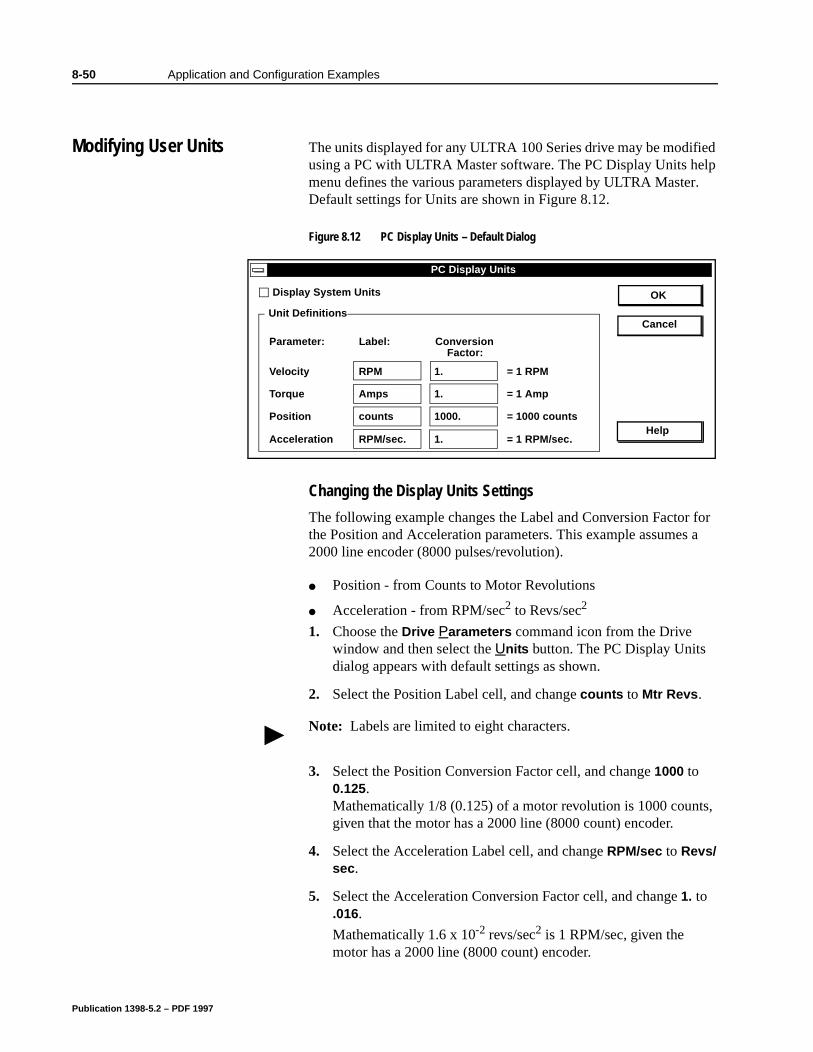
8-50 Application and Configuration Examples
8Application and Configuration Examples
Modifying User Units The units displayed for any ULTRA 100 Series drive may be modified using a PC with ULTRA Master software. The PC Display Units help menu defines the various parameters displayed by ULTRA Master. Default settings for Units are shown in Figure 8.12.
Changing the Display Units Settings
The following example changes the Label and Conversion Factor for the Position and Acceleration parameters. This example assumes a 2000 line encoder (8000 pulses/revolution).
Position - from Counts to Motor Revolutions
Acceleration - from RPM/sec2 to Revs/sec2
1. Choose the Drive Parameters command icon from the Drive window and then select the Units button. The PC Display Units dialog appears with default settings as shown.
2. Select the Position Label cell, and change counts to Mtr Revs.
3. Select the Position Conversion Factor cell, and change 1000 to 0.125. Mathematically 1/8 (0.125) of a motor revolution is 1000 counts, given that the motor has a 2000 line (8000 count) encoder.
4. Select the Acceleration Label cell, and change RPM/sec to Revs/sec.
5. Select the Acceleration Conversion Factor cell, and change 1. to .016.
Mathematically 1.6 x 10⁻² revs/sec2 is 1 RPM/sec, given the motor has a 2000 line (8000 count) encoder.
Figure 8.12 PC Display Units – Default Dialog Intro
Intro
PC Display Units
Display System Units OK
Cancel
Help
Parameter:
Velocity
Torque
Position
Acceleration
Label: Conversion
RPM
Amps
counts
RPM/sec.
1.
1.
1.
1000.
= 1 RPM
= 1 Amp
= 1000 counts
= 1 RPM/sec.
Unit Definitions
Factor:
Note: Labels are limited to eight characters.
Publication 1398-5.2 – PDF 1997
Application and Configuration Examples 8-51
6. Choose OK to exit the PC Display Units dialog.
The modified units will be displayed where appropriate within the ULTRA Master windows. For example, these changes cause the Indexing tab in the Drive Parameters window to display:
Distance in Mtr Revs
Acceleration in Revs/sec2
Deceleration in Revs/sec2
The following units were not effected by the changes:
Dwell in msec
Velocity in RPM
Publication 1398-5.2 – PDF 1997

8-52 Application and Configuration Examples
Publication 1398-5.2 – PDF 1997
Chapter 9
f
Tuning Chapter 9
ULTRA 100 Series drives are tuned quickly and easily for a wide variety of applications. Two tuning modes are available through the software:
Auto Tune
Manual Tune
Tuning Guidelines The following tuning guidelines briefly describe the tuning adjustments. These guidelines provide you with a basic reference point should the application require additional adjustments.
General Tuning Rules
Tune the velocity loop first and then, if the drive uses following or step/direction commands, tune the position loop.
To widen the velocity loop bandwidth, increase the P-gain setting, decrease the I-gain setting or increase the low-pass filter bandwidth. This provides a faster rise time and increases drive response.
To increase stiffness, increase the I-gain setting. It rejects load disturbance and compensates for system friction.
To reduce velocity loop overshoot, increase P-gain or decrease I-gain.
To reduce mechanical resonance, use a stiffer mechanical coupling or decrease the low-pass filter value and the velocity loop update rate.
If the motor oscillates, decrease either individually or together the:
– P-gain– I-gain– low-pass filter bandwidth.
High Inertia Loads
Proper compensation of load inertia may not be simply a matter oincreasing the P-gain and I-gain settings. Problems are often encountered when tuning systems with a high load to motor inertiaratio.
Publication 1398-5.2 – PDF 1997
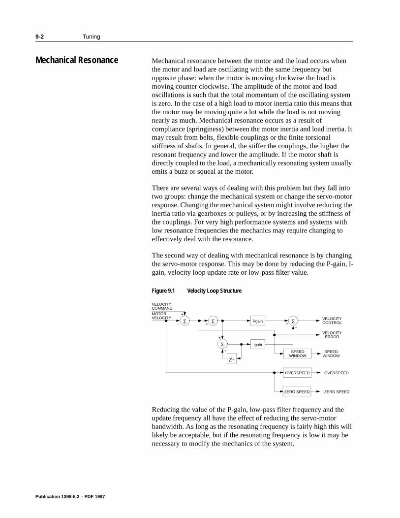
9-2 Tuning
Mechanical Resonance Mechanical resonance between the motor and the load occurs when the motor and load are oscillating with the same frequency but opposite phase: when the motor is moving clockwise the load is moving counter clockwise. The amplitude of the motor and load oscillations is such that the total momentum of the oscillating system is zero. In the case of a high load to motor inertia ratio this means that the motor may be moving quite a lot while the load is not moving nearly as much. Mechanical resonance occurs as a result of compliance (springiness) between the motor inertia and load inertia. It may result from belts, flexible couplings or the finite torsional stiffness of shafts. In general, the stiffer the couplings, the higher the resonant frequency and lower the amplitude. If the motor shaft is directly coupled to the load, a mechanically resonating system usually emits a buzz or squeal at the motor.
There are several ways of dealing with this problem but they fall into two groups: change the mechanical system or change the servo-motor response. Changing the mechanical system might involve reducing the inertia ratio via gearboxes or pulleys, or by increasing the stiffness of the couplings. For very high performance systems and systems with low resonance frequencies the mechanics may require changing to effectively deal with the resonance.
The second way of dealing with mechanical resonance is by changing the servo-motor response. This may be done by reducing the P-gain, I-gain, velocity loop update rate or low-pass filter value.
Reducing the value of the P-gain, low-pass filter frequency and the update frequency all have the effect of reducing the servo-motor bandwidth. As long as the resonating frequency is fairly high this will likely be acceptable, but if the resonating frequency is low it may be necessary to modify the mechanics of the system.
Figure 9.1 Velocity Loop Structure
VELOCITYCOMMANDMOTORVELOCITY VELOCITY
CONTROL
VELOCITYERROR
SPEEDWINDOW
OVERSPEED
ZERO SPEED
+
Σ- + Σ
+
Σ+
Pgain
Igain
Ζ-1
Σ++
SPEEDWINDOW
OVERSPEED
ZERO SPEED
Publication 1398-5.2 – PDF 1997
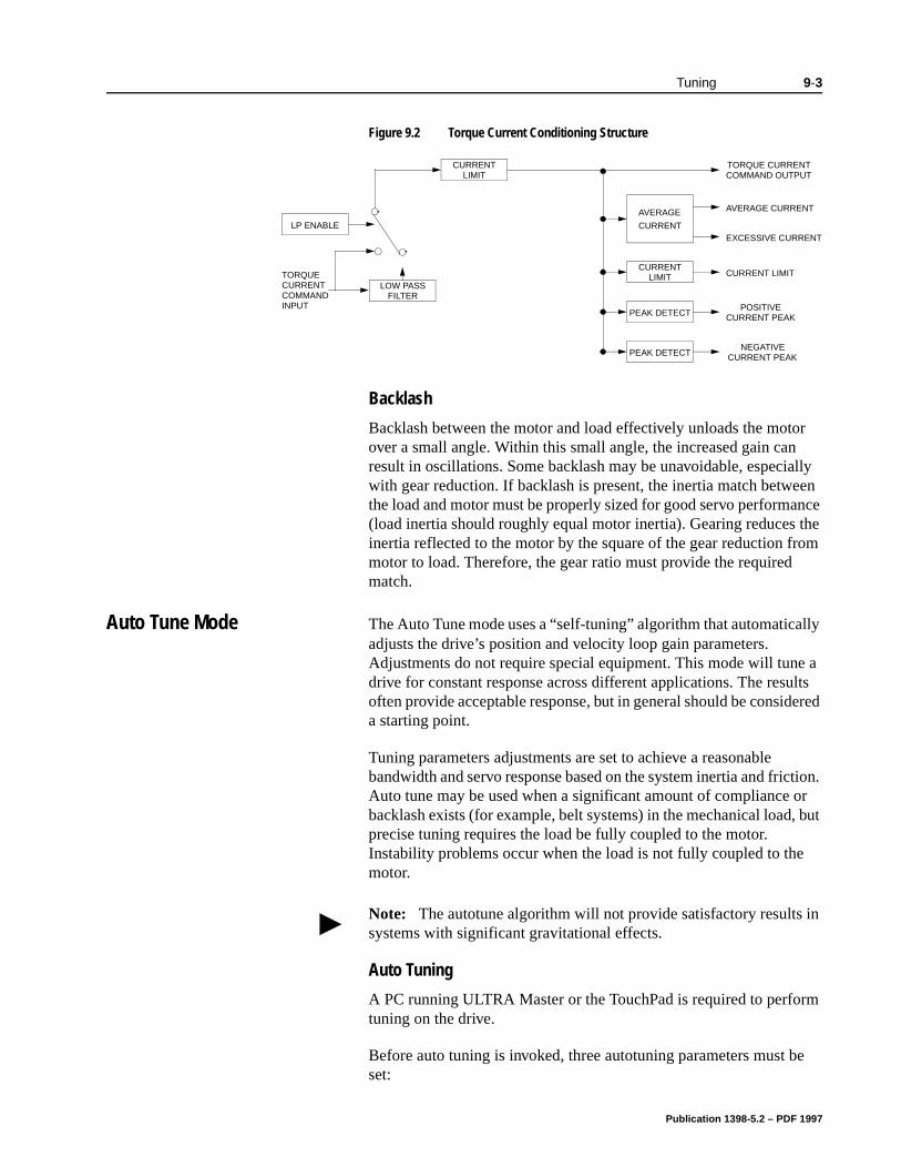
Tuning 9-3
lly
e a lts ered
tion. r
, but
rm
e
Backlash
Backlash between the motor and load effectively unloads the motor over a small angle. Within this small angle, the increased gain can result in oscillations. Some backlash may be unavoidable, especially with gear reduction. If backlash is present, the inertia match between the load and motor must be properly sized for good servo performance (load inertia should roughly equal motor inertia). Gearing reduces the inertia reflected to the motor by the square of the gear reduction from motor to load. Therefore, the gear ratio must provide the required match.
Auto Tune Mode The Auto Tune mode uses a “self-tuning” algorithm that automaticaadjusts the drive’s position and velocity loop gain parameters. Adjustments do not require special equipment. This mode will tundrive for constant response across different applications. The resuoften provide acceptable response, but in general should be consida starting point.
Tuning parameters adjustments are set to achieve a reasonable bandwidth and servo response based on the system inertia and fricAuto tune may be used when a significant amount of compliance obacklash exists (for example, belt systems) in the mechanical loadprecise tuning requires the load be fully coupled to the motor. Instability problems occur when the load is not fully coupled to themotor.
Auto Tuning
A PC running ULTRA Master or the TouchPad is required to perfotuning on the drive.
Before auto tuning is invoked, three autotuning parameters must bset:
Figure 9.2 Torque Current Conditioning Structure
PEAK DETECT
PEAK DETECT
CURRENT
AVERAGE
LIMIT
CURRENT
CURRENTLIMIT
LP ENABLE
LOW PASSFILTER
TORQUECURRENTCOMMANDINPUT
TORQUE CURRENTCOMMAND OUTPUT
AVERAGE CURRENT
CURRENT LIMIT
POSITIVECURRENT PEAK
NEGATIVECURRENT PEAK
EXCESSIVE CURRENT
Note: The autotune algorithm will not provide satisfactory results in systems with significant gravitational effects.
Publication 1398-5.2 – PDF 1997
9-4 Tuning
e
a ld
n-
a
Distance sets the rotation limit of the motor. This is the maximum distance the motor is allowed to move during any one test.
Step Current sets the amount of current given to the motor during the test. If this is set too low, a system may not move enough to gather sufficient data, if it is set too high the test will be too short and very jerky.
Motor Direction (Forward Only/Reverse Only/Bi-directional) sets the rotational direction for the test. The bi-directional test does the same test in both directions, with the forward rotation first.
Auto tune procedures are explained for each drive configuration in “Application and Configuration Examples” starting on page 8-1. Thfollowing steps generalize the ULTRA Master tuning procedures. Similar procedures apply for the TouchPad.
When autotuning is selected, the drive rotates the motor shaft for short time interval, typically a few seconds. Motor movement shounot exceed 30 seconds.
1. Choose the Tuning command icon from the Drive window.
2. Choose Auto Tune from the Tuning window. This activates the Auto Tune Command and Motor Direction boxes within the Tuing window. Then enter or select:
• appropriate values for Distance in the Auto Tune Command box,
• appropriate values for Step Current in the Auto Tune Com-mand box, and
• an appropriate motor rotation in the Motor Direction box onPC, either:
– BiDirectional, if the motor will be powered in both the forward and reverse directions.
– Forward Only , if the machinery is designed to operate only in the forward direction.
– Reverse Only , if the motor will be powered only in the reverse direction.
Note: Autotuning in the bi-directional mode includes two different tests.
!
Intro
ATTENTION: Rotating motor shafts can cause extensive damage and injury. Motors must be properly guarded dur-ing testing and installation.
Publication 1398-5.2 – PDF 1997
Tuning 9-5
Use the default settings if you are uncertain about what values to enter. The default settings are set to values appropriate to the drive and motor combination selected during drive initialization.
3. Enable the drive.
4. Choose Start from the Tuning window. The drive rotates the motor shaft and then motion will cease. The calculated gains are displayed and the drive is disabled.
5. Disable the drive manually.
6. Choose Normal Drive Operation from the Tuning window.
7. Enable the drive.
8. Choose Close to exit the Tuning window.
Note: Auto tuning does not have a velocity limit, but it does adhere to the motor Overspeed setting in the Drive Parameters window.
Publication 1398-5.2 – PDF 1997
9-6 Tuning
nd
ced
of
P ssist
Manual Tune Mode Manual tuning may be used to adjust the gain settings and filter frequency of the velocity and position regulator. The following sections briefly explain these settings. An understanding of the function for each type of gain and filtering will allow you to effectively tune the system.
Two types of manual tuning are available:
Velocity tuning
Position tuning.
Before manual tuning is invoked, the Velocity, Distance and Motor Direction parameters must be set. Refer to “Auto Tune Mode” on page 9-3 for information on setting these parameters.
The velocity loop should always be tuned before the position loop, as velocity loop tuning affects the position loop response.
Gain settings and signal filtering are the primary methods to electrically tune a system. An understanding of the types of gain atheir purposes, as well as a general understanding of filtering, areessential background knowledge to properly tune a servo system.
Filters
The velocity regulator has one low pass filter. The filter bandwidthrange is from 1 Hz to 992 Hz. The filter serves two purposes:
Adjusts the frequency range to remove or filter the noise produby encoder resolution.
Reduces the amount of the mechanical resonance in the mechanical system (e.g., belt systems).
Similar results may often be achieved by reducing the update ratethe velocity loop.
Gains
Manual Tuning
Manual tuning may be used to adjust the gain control parameters and I, and the filters. A square wave is generated by the drive to ain the adjustment. Manual velocity tuning requires the following:
Step Period value to be specified
Publication 1398-5.2 – PDF 1997
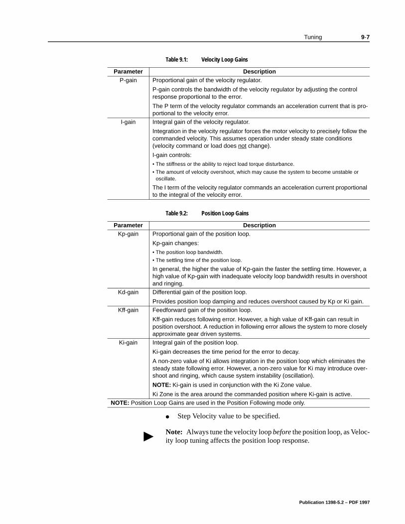
Tuning 9-7
Step Velocity value to be specified.
Table 9.1: Velocity Loop Gains
Parameter DescriptionP-gain Proportional gain of the velocity regulator.
P-gain controls the bandwidth of the velocity regulator by adjusting the control response proportional to the error.
The P term of the velocity regulator commands an acceleration current that is pro-portional to the velocity error.
I-gain Integral gain of the velocity regulator.
Integration in the velocity regulator forces the motor velocity to precisely follow the commanded velocity. This assumes operation under steady state conditions (velocity command or load does not change).
I-gain controls:
• The stiffness or the ability to reject load torque disturbance.
• The amount of velocity overshoot, which may cause the system to become unstable or oscillate.
The I term of the velocity regulator commands an acceleration current proportional to the integral of the velocity error.
Table 9.2: Position Loop Gains
Parameter DescriptionKp-gain Proportional gain of the position loop.
Kp-gain changes:
• The position loop bandwidth.
• The settling time of the position loop.
In general, the higher the value of Kp-gain the faster the settling time. However, a high value of Kp-gain with inadequate velocity loop bandwidth results in overshoot and ringing.
Kd-gain Differential gain of the position loop.
Provides position loop damping and reduces overshoot caused by Kp or Ki gain. Kff-gain Feedforward gain of the position loop.
Kff-gain reduces following error. However, a high value of Kff-gain can result in position overshoot. A reduction in following error allows the system to more closely approximate gear driven systems.
Ki-gain Integral gain of the position loop.
Ki-gain decreases the time period for the error to decay.
A non-zero value of Ki allows integration in the position loop which eliminates the steady state following error. However, a non-zero value for Ki may introduce over-shoot and ringing, which cause system instability (oscillation).
NOTE: Ki-gain is used in conjunction with the Ki Zone value.
Ki Zone is the area around the commanded position where Ki-gain is active.NOTE: Position Loop Gains are used in the Position Following mode only.
Note: Always tune the velocity loop before the position loop, as Veloc-ity loop tuning affects the position loop response.
Publication 1398-5.2 – PDF 1997

9-8 Tuning
Tuning the Velocity Loop
The Auto Tune procedure provides a starting point for velocity loop tuning. Manual tuning is desirable when very precise adjustments are required.
The following steps describe how to manually tune the velocity loop. These steps precede the manual position loop tuning procedure, which should follow velocity loop tuning.
1. Disable the drive.
2. Choose Manual Tune (Velocity Step) from the Tuning window.
3. Enter the desired step Velocity (rpm) of the internal square wave generator.
4. Enter the desired Time to complete one cycle of the square wave of the internal step velocity.
5. Select the desired Motor Direction (Forward Only, Reverse Only, or Bi-Directional).
6. Select the Oscilloscope.
7. Enable the drive.
8. Choose Start. The motor should start moving and the oscilloscope will display the commanded velocity and the motor velocity.
9. While monitoring the motor velocity waveform, increase P-gain until the desired rise time is achieved.
10. While monitoring the motor velocity waveform, increase I-gain until an acceptable amount of overshoot is reached.
11. Apply filtering by selecting Filters, and then select Filter Enable.
12. While monitoring the motor velocity waveform, decrease the filter Bandwidth until the overshoot begins to increase (in many appli-cations the filter is not necessary).
13. Choose Stop.
14. Disable the drive.
15. Choose Normal Drive Operation.
16. Choose Close.
17. Enable the drive.
The drive’s velocity loop is tuned.
Publication 1398-5.2 – PDF 1997
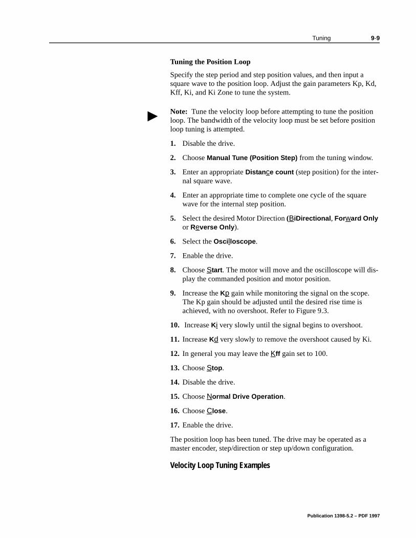
Tuning 9-9
Tuning the Position Loop
Specify the step period and step position values, and then input a square wave to the position loop. Adjust the gain parameters Kp, Kd, Kff, Ki, and Ki Zone to tune the system.
1. Disable the drive.
2. Choose Manual Tune (Position Step) from the tuning window.
3. Enter an appropriate Distance count (step position) for the inter-nal square wave.
4. Enter an appropriate time to complete one cycle of the square wave for the internal step position.
5. Select the desired Motor Direction (BiDirectional, Forward Only or Reverse Only).
6. Select the Oscilloscope.
7. Enable the drive.
8. Choose Start. The motor will move and the oscilloscope will dis-play the commanded position and motor position.
9. Increase the Kp gain while monitoring the signal on the scope. The Kp gain should be adjusted until the desired rise time is achieved, with no overshoot. Refer to Figure 9.3.
10. Increase Ki very slowly until the signal begins to overshoot.
11. Increase Kd very slowly to remove the overshoot caused by Ki.
12. In general you may leave the Kff gain set to 100.
13. Choose Stop.
14. Disable the drive.
15. Choose Normal Drive Operation.
16. Choose Close.
17. Enable the drive.
The position loop has been tuned. The drive may be operated as a master encoder, step/direction or step up/down configuration.
Velocity Loop Tuning Examples
Note: Tune the velocity loop before attempting to tune the position loop. The bandwidth of the velocity loop must be set before position loop tuning is attempted.
Publication 1398-5.2 – PDF 1997
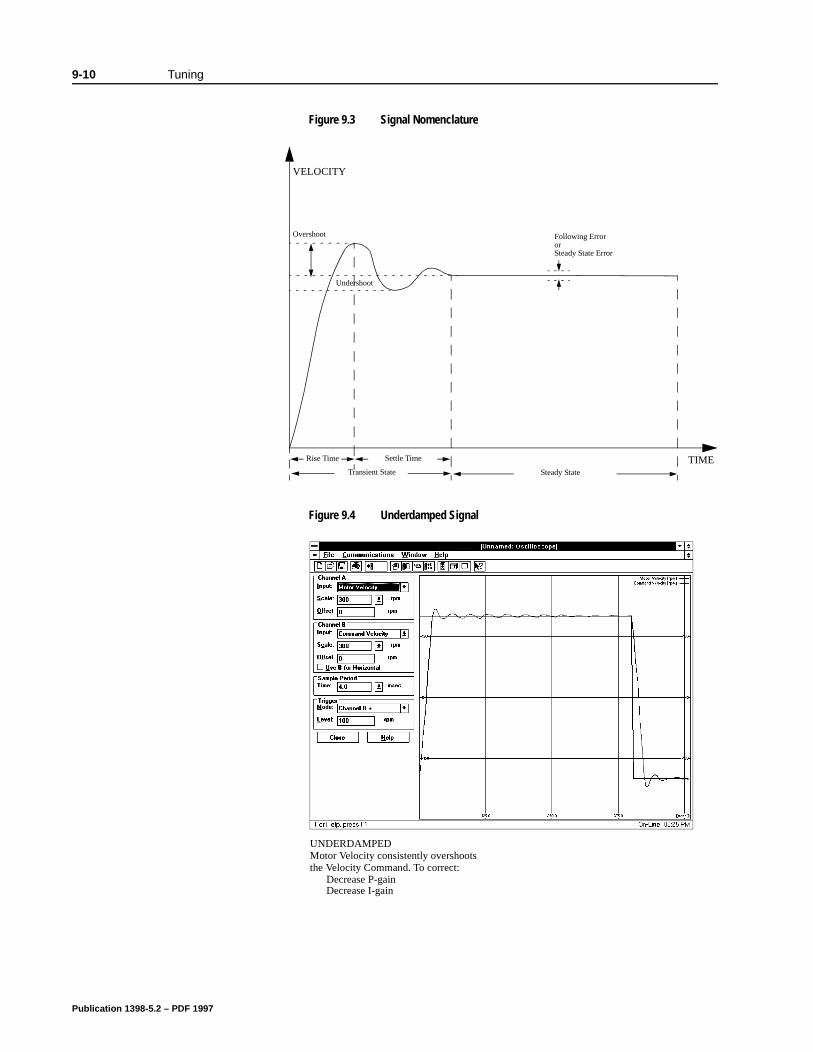
9-10 Tuning
Figure 9.3 Signal NomenclatureIntro
Figure 9.4 Underdamped SignalIntro
Transient State
VELOCITY
TIMESettle TimeRise Time
Following ErrororSteady State Error
Overshoot
Steady State
Undershoot
UNDERDAMPED
Decrease P-gain Decrease I-gain
Motor Velocity consistently overshootsthe Velocity Command. To correct:
Publication 1398-5.2 – PDF 1997
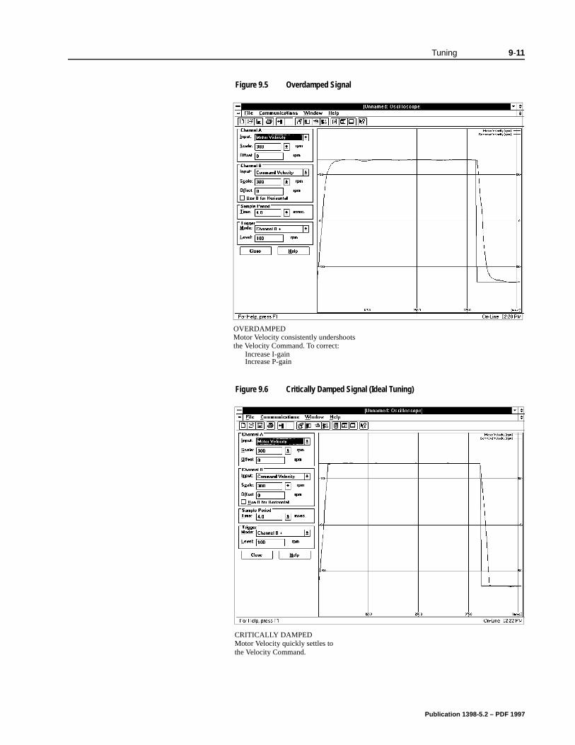
Tuning 9-11
Figure 9.5 Overdamped SignalIntro
Figure 9.6 Critically Damped Signal (Ideal Tuning)Intro
OVERDAMPED
Increase I-gain
Motor Velocity consistently undershootsthe Velocity Command. To correct:
Increase P-gain
CRITICALLY DAMPEDMotor Velocity quickly settles tothe Velocity Command.
Publication 1398-5.2 – PDF 1997

9-12 Tuning
Publication 1398-5.2 – PDF 1997
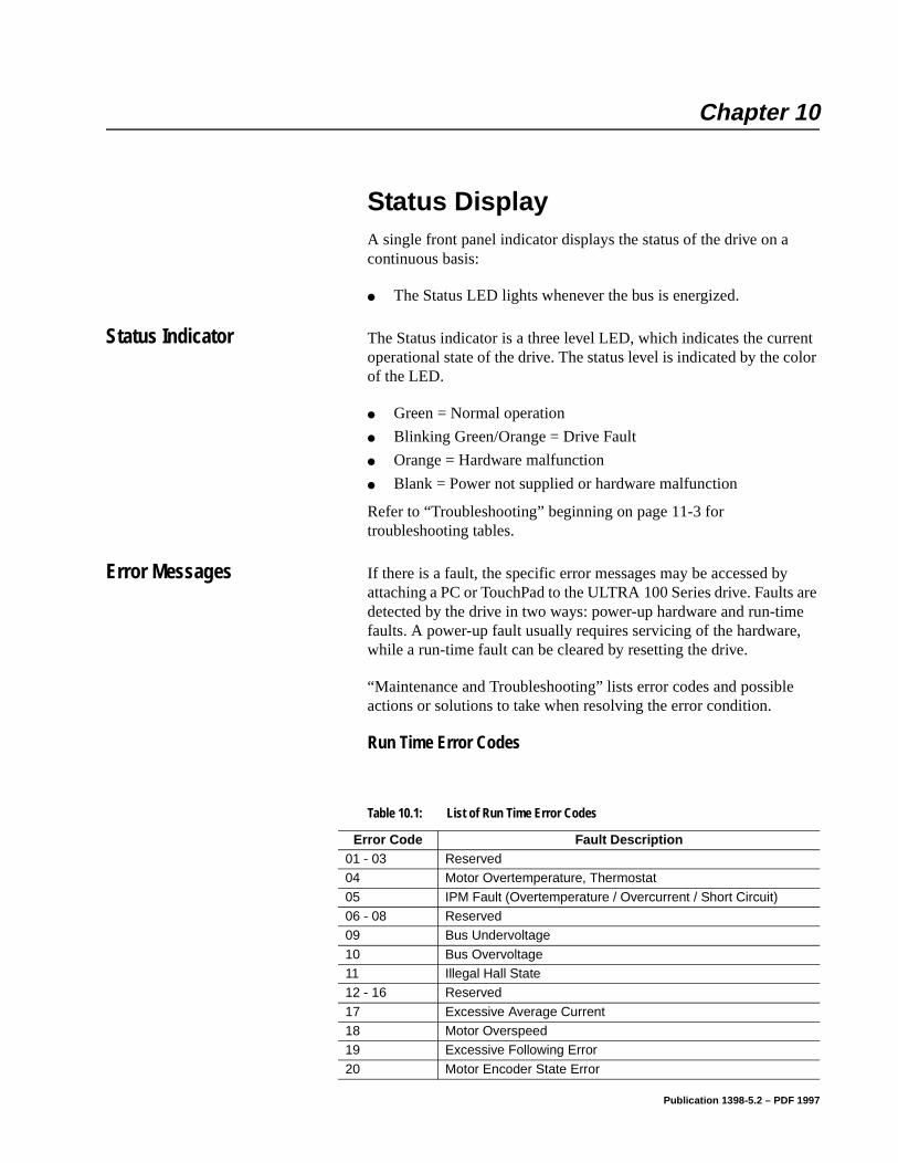
Chapter 10
are e ,
Status Display Chapter 10
A single front panel indicator displays the status of the drive on a continuous basis:
The Status LED lights whenever the bus is energized.
Status Indicator The Status indicator is a three level LED, which indicates the current operational state of the drive. The status level is indicated by the color of the LED.
Green = Normal operation
Blinking Green/Orange = Drive Fault
Orange = Hardware malfunction
Blank = Power not supplied or hardware malfunction
Refer to “Troubleshooting” beginning on page 11-3 for troubleshooting tables.
Error Messages If there is a fault, the specific error messages may be accessed byattaching a PC or TouchPad to the ULTRA 100 Series drive. Faultsdetected by the drive in two ways: power-up hardware and run-timfaults. A power-up fault usually requires servicing of the hardwarewhile a run-time fault can be cleared by resetting the drive.
“Maintenance and Troubleshooting” lists error codes and possibleactions or solutions to take when resolving the error condition.
Run Time Error Codes
Table 10.1: List of Run Time Error Codes
Error Code Fault Description01 - 03 Reserved04 Motor Overtemperature, Thermostat
05 IPM Fault (Overtemperature / Overcurrent / Short Circuit)06 - 08 Reserved09 Bus Undervoltage
10 Bus Overvoltage11 Illegal Hall State12 - 16 Reserved
17 Excessive Average Current18 Motor Overspeed19 Excessive Following Error
20 Motor Encoder State Error
Publication 1398-5.2 – PDF 1997
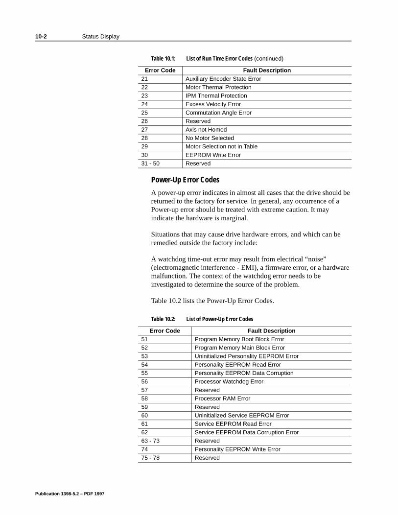
10-2 Status Display
re
Power-Up Error Codes
A power-up error indicates in almost all cases that the drive should be returned to the factory for service. In general, any occurrence of a Power-up error should be treated with extreme caution. It may indicate the hardware is marginal.
Situations that may cause drive hardware errors, and which can be remedied outside the factory include:
A watchdog time-out error may result from electrical “noise” (electromagnetic interference - EMI), a firmware error, or a hardwamalfunction. The context of the watchdog error needs to be investigated to determine the source of the problem.
Table 10.2 lists the Power-Up Error Codes.
21 Auxiliary Encoder State Error 22 Motor Thermal Protection23 IPM Thermal Protection
24 Excess Velocity Error25 Commutation Angle Error26 Reserved
27 Axis not Homed28 No Motor Selected29 Motor Selection not in Table
30 EEPROM Write Error31 - 50 Reserved
Table 10.1: List of Run Time Error Codes (continued)
Error Code Fault Description
Table 10.2: List of Power-Up Error Codes
Error Code Fault Description51 Program Memory Boot Block Error52 Program Memory Main Block Error
53 Uninitialized Personality EEPROM Error54 Personality EEPROM Read Error55 Personality EEPROM Data Corruption
56 Processor Watchdog Error57 Reserved58 Processor RAM Error
59 Reserved60 Uninitialized Service EEPROM Error 61 Service EEPROM Read Error
62 Service EEPROM Data Corruption Error 63 - 73 Reserved74 Personality EEPROM Write Error
75 - 78 Reserved
Publication 1398-5.2 – PDF 1997
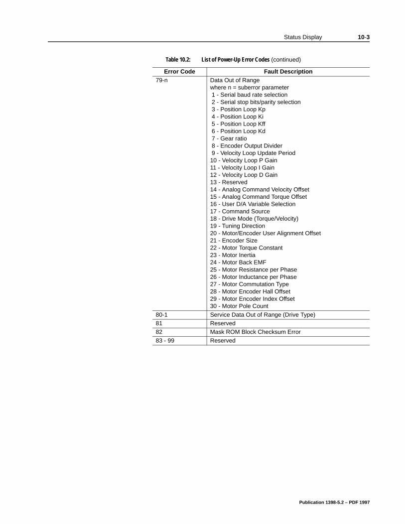
Status Display 10-3
79-n Data Out of Rangewhere n = suberror parameter 1 - Serial baud rate selection 2 - Serial stop bits/parity selection 3 - Position Loop Kp 4 - Position Loop Ki 5 - Position Loop Kff 6 - Position Loop Kd 7 - Gear ratio 8 - Encoder Output Divider 9 - Velocity Loop Update Period 10 - Velocity Loop P Gain 11 - Velocity Loop I Gain 12 - Velocity Loop D Gain 13 - Reserved 14 - Analog Command Velocity Offset 15 - Analog Command Torque Offset 16 - User D/A Variable Selection 17 - Command Source 18 - Drive Mode (Torque/Velocity) 19 - Tuning Direction 20 - Motor/Encoder User Alignment Offset 21 - Encoder Size 22 - Motor Torque Constant 23 - Motor Inertia 24 - Motor Back EMF 25 - Motor Resistance per Phase 26 - Motor Inductance per Phase 27 - Motor Commutation Type 28 - Motor Encoder Hall Offset 29 - Motor Encoder Index Offset 30 - Motor Pole Count
80-1 Service Data Out of Range (Drive Type)81 Reserved82 Mask ROM Block Checksum Error
83 - 99 Reserved
Table 10.2: List of Power-Up Error Codes (continued)
Error Code Fault Description
Publication 1398-5.2 – PDF 1997

10-4 Status Display
Publication 1398-5.2 – PDF 1997
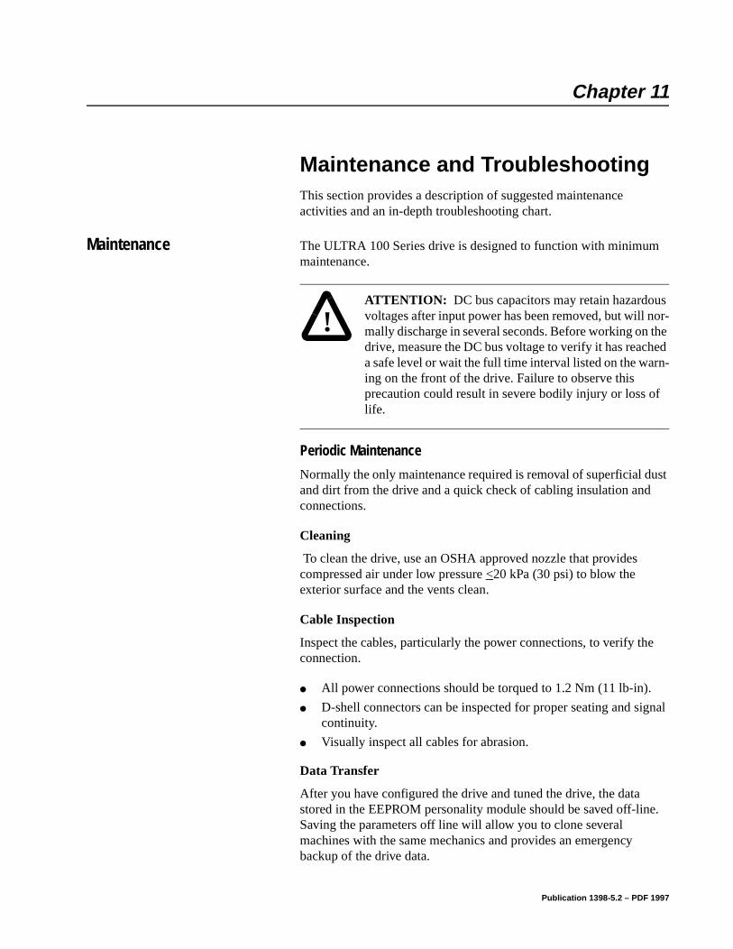
Chapter 11
Maintenance and Troubleshooting Chapter 11
This section provides a description of suggested maintenance activities and an in-depth troubleshooting chart.
Maintenance The ULTRA 100 Series drive is designed to function with minimum maintenance.
Periodic Maintenance
Normally the only maintenance required is removal of superficial dust and dirt from the drive and a quick check of cabling insulation and connections.
Cleaning
To clean the drive, use an OSHA approved nozzle that provides compressed air under low pressure <20 kPa (30 psi) to blow the exterior surface and the vents clean.
Cable Inspection
Inspect the cables, particularly the power connections, to verify the connection.
All power connections should be torqued to 1.2 Nm (11 lb-in).
D-shell connectors can be inspected for proper seating and signal continuity.
Visually inspect all cables for abrasion.
Data Transfer
After you have configured the drive and tuned the drive, the data stored in the EEPROM personality module should be saved off-line. Saving the parameters off line will allow you to clone several machines with the same mechanics and provides an emergency backup of the drive data.
!
Intro
ATTENTION: DC bus capacitors may retain hazardous voltages after input power has been removed, but will nor-mally discharge in several seconds. Before working on the drive, measure the DC bus voltage to verify it has reached a safe level or wait the full time interval listed on the warn-ing on the front of the drive. Failure to observe this precaution could result in severe bodily injury or loss of life.
Publication 1398-5.2 – PDF 1997

11-2 Maintenance and Troubleshooting
To transfer the data from the drive to a PC:
1. While on-line with a drive, click on File in the toolbar menu.
2. Select Save As..., the Save As window will appear.
3. Enter the file name and press ENTER or choose OK to save.
To transfer the data from a PC to a drive:
1. Close all windows in ULTRA Master.
2. Choose File in the toolbar menu.
3. Choose Open.
4. Select the desired file name or enter the file name to be loaded and press ENTER or choose OK.
If you do not know the name of the file to be loaded, select the correct directory from the Directories box and select the file name from the displayed list of file names. The ULTRA Master Off-Line Drive window will appear along with the selected file name.
5. Select Communications from the toolbar menu.
6. Select Overwrite Drive Parameters.The Drive Select window will appear.
7. Select the drive to be configured, and then press ENTER or choose OK to load the parameters into the personality module.
Firmware Upgrading ULTRA 100 Series drives may be upgraded in the field to the latest version of firmware. Firmware versions are available from the Allen-Bradley Product Support group. The procedure describes how to reload the firmware installed in your drive using the Upgrade Firmware command available in ULTRA Master software.
ULTRA Master provides checks and controls through message boxes which ensure that the loading of firmware is performed properly.
Firmware Upgrade Procedure using ULTRA Master
1. Copy the new firmware into the Firmware subdirectory of the ULTRA Master application directory.
2. Start ULTRA Master.
Publication 1398-5.2 – PDF 1997
Maintenance and Troubleshooting 11-3
on this
a
ake
.
3. When the Drive Select window appears, select Cancel. The Drive Select window closes without connecting to the drive.
4. Choose Upgrade Firmware from the File menu. The Drive Select window will appear.
5. Select the drive to upgrade, and then select OK. The Select Firm-ware File window will appear.
6. The Select Firmware File window contains a list of firmware files identified by version information. Only the files that can be applied to the connected drive are displayed, which minimizes the danger of transferring an incorrect file. To select the firmware files:
• Select the appropriate file to upgrade the drive firmware.
• Select OK when the file is highlighted.
A visual indicator traces the progress of the firmware upgrade.
7. When the upgrade is complete a dialog box confirms completiof the upgrade and reminds you that the drive must be reset attime.
• Select Yes if you want to perform a software reset of the drive.
• Select No if you wish to reset the drive by removing power.
Troubleshooting A single LED on the front panel indicates the status of the drive oncontinuous basis:
Green = Normal operation
Blinking Green/Orange = Drive Fault
Orange = Hardware malfunction
Blank = Power not supplied or hardware malfunction
A table of problems, potential causes, and appropriate actions to tto resolve the problem is included below.
If problems persist after attempting to carefully troubleshoot the system, please contact your local distributor for further assistance
Note: Do not remove power or reset either the drive or the PC during the upgrade. Any interruption of the firmware upgrade could cause the drive to become inoperable.
Publication 1398-5.2 – PDF 1997
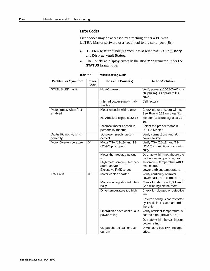
11-4 Maintenance and Troubleshooting
Error Codes
Error codes may be accessed by attaching either a PC with ULTRA Master software or a TouchPad to the serial port (J5):
ULTRA Master displays errors in two windows: Fault History and Display Fault Status,
The TouchPad display errors in the DrvStat parameter under the STATUS branch title.
Table 11.1: Troubleshooting Guide
Problem or Symptom Error Code
Possible Cause(s) Action/Solution
STATUS LED not lit No AC power Verify power (115/230VAC sin-gle phase) is applied to the drive.
Internal power supply mal-function.
Call factory
Motor jumps when first enabled
Motor encoder wiring error Check motor encoder wiring. See Figure 6.38 on page 31
No Absolute signal at J2-16 Monitor Absolute signal at J2-16.
Incorrect motor chosen in personality module
Select the proper motor in ULTRA Master.
Digital I/O not working correctly
I/O power supply discon-nected
Verify connections and I/O power source
Motor Overtemperature 04 Motor TS+ (J2-19) and TS- (J2-20) pins open
Verify TS+ (J2-19) and TS- (J2-20) connections for conti-nuity.
Motor thermostat trips due to:High motor ambient temper-ature, and/or Excessive RMS torque
Operate within (not above) the continuous torque rating for the ambient temperature (40°C maximum). Lower ambient temperature.
IPM Fault 05 Motor cables shorted Verify continuity of motor power cable and connector.
Motor winding shorted inter-nally
Check for short on R,S,T and Gnd windings of the motor.
Drive temperature too high Check for clogged or defective fan.
Ensure cooling is not restricted by insufficient space around the unit.
Operation above continuous power rating
Verify ambient temperature is not too high (above 60° C).
Operate within the continuous power rating.
Output short circuit or over-current
Drive has a bad IPM, replace drive.
Publication 1398-5.2 – PDF 1997
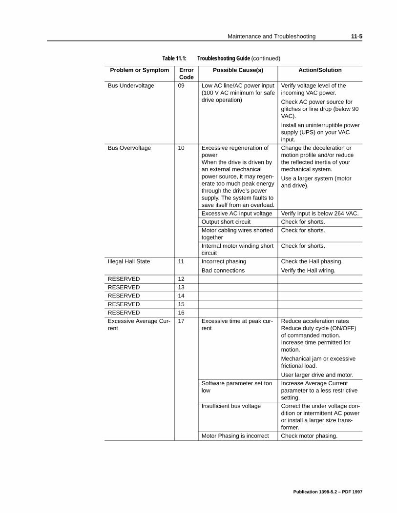
Maintenance and Troubleshooting 11-5
Bus Undervoltage 09 Low AC line/AC power input (100 V AC minimum for safe drive operation)
Verify voltage level of the incoming VAC power.
Check AC power source for glitches or line drop (below 90 VAC).
Install an uninterruptible power supply (UPS) on your VAC input.
Bus Overvoltage 10 Excessive regeneration of powerWhen the drive is driven by an external mechanical power source, it may regen-erate too much peak energy through the drive’s power supply. The system faults to save itself from an overload.
Change the deceleration or motion profile and/or reduce the reflected inertia of your mechanical system.
Use a larger system (motor and drive).
Excessive AC input voltage Verify input is below 264 VAC. Output short circuit Check for shorts.
Motor cabling wires shorted together
Check for shorts.
Internal motor winding short circuit
Check for shorts.
Illegal Hall State 11 Incorrect phasing
Bad connections
Check the Hall phasing.
Verify the Hall wiring.
RESERVED 12RESERVED 13RESERVED 14
RESERVED 15RESERVED 16Excessive Average Cur-rent
17 Excessive time at peak cur-rent
Reduce acceleration ratesReduce duty cycle (ON/OFF) of commanded motion. Increase time permitted for motion.
Mechanical jam or excessive frictional load.
User larger drive and motor.Software parameter set too low
Increase Average Current parameter to a less restrictive setting.
Insufficient bus voltage Correct the under voltage con-dition or intermittent AC power or install a larger size trans-former.
Motor Phasing is incorrect Check motor phasing.
Table 11.1: Troubleshooting Guide (continued)
Problem or Symptom Error Code
Possible Cause(s) Action/Solution
Publication 1398-5.2 – PDF 1997
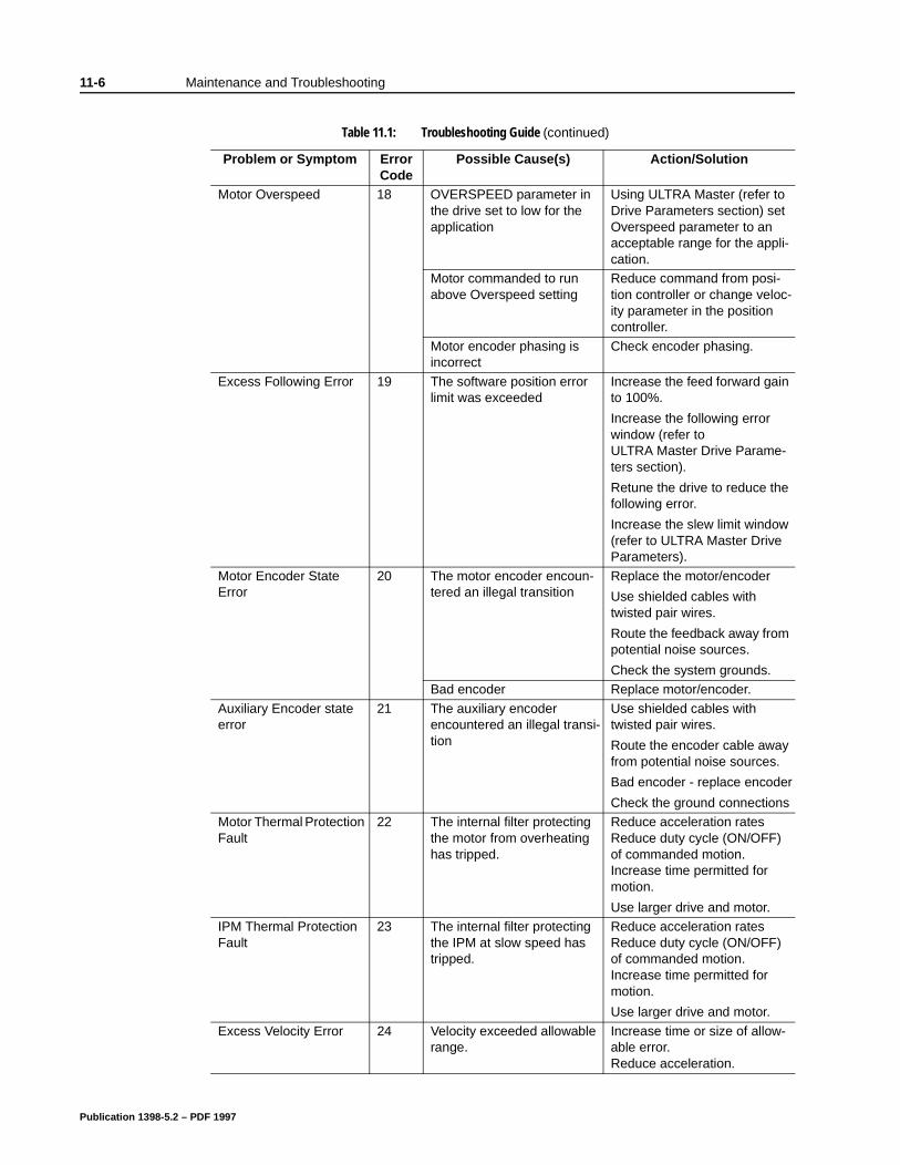
11-6 Maintenance and Troubleshooting
Motor Overspeed 18 OVERSPEED parameter in the drive set to low for the application
Using ULTRA Master (refer to Drive Parameters section) set Overspeed parameter to an acceptable range for the appli-cation.
Motor commanded to run above Overspeed setting
Reduce command from posi-tion controller or change veloc-ity parameter in the position controller.
Motor encoder phasing is incorrect
Check encoder phasing.
Excess Following Error 19 The software position error limit was exceeded
Increase the feed forward gain to 100%.
Increase the following error window (refer to ULTRA Master Drive Parame-ters section).
Retune the drive to reduce the following error.
Increase the slew limit window (refer to ULTRA Master Drive Parameters).
Motor Encoder State Error
20 The motor encoder encoun-tered an illegal transition
Replace the motor/encoder
Use shielded cables with twisted pair wires.
Route the feedback away from potential noise sources.
Check the system grounds.Bad encoder Replace motor/encoder.
Auxiliary Encoder state error
21 The auxiliary encoder encountered an illegal transi-tion
Use shielded cables with twisted pair wires.
Route the encoder cable away from potential noise sources.
Bad encoder - replace encoder
Check the ground connectionsMotor Thermal Protection Fault
22 The internal filter protecting the motor from overheating has tripped.
Reduce acceleration ratesReduce duty cycle (ON/OFF) of commanded motion. Increase time permitted for motion.
Use larger drive and motor.IPM Thermal Protection Fault
23 The internal filter protecting the IPM at slow speed has tripped.
Reduce acceleration ratesReduce duty cycle (ON/OFF) of commanded motion. Increase time permitted for motion.
Use larger drive and motor.
Excess Velocity Error 24 Velocity exceeded allowable range.
Increase time or size of allow-able error.Reduce acceleration.
Table 11.1: Troubleshooting Guide (continued)
Problem or Symptom Error Code
Possible Cause(s) Action/Solution
Publication 1398-5.2 – PDF 1997
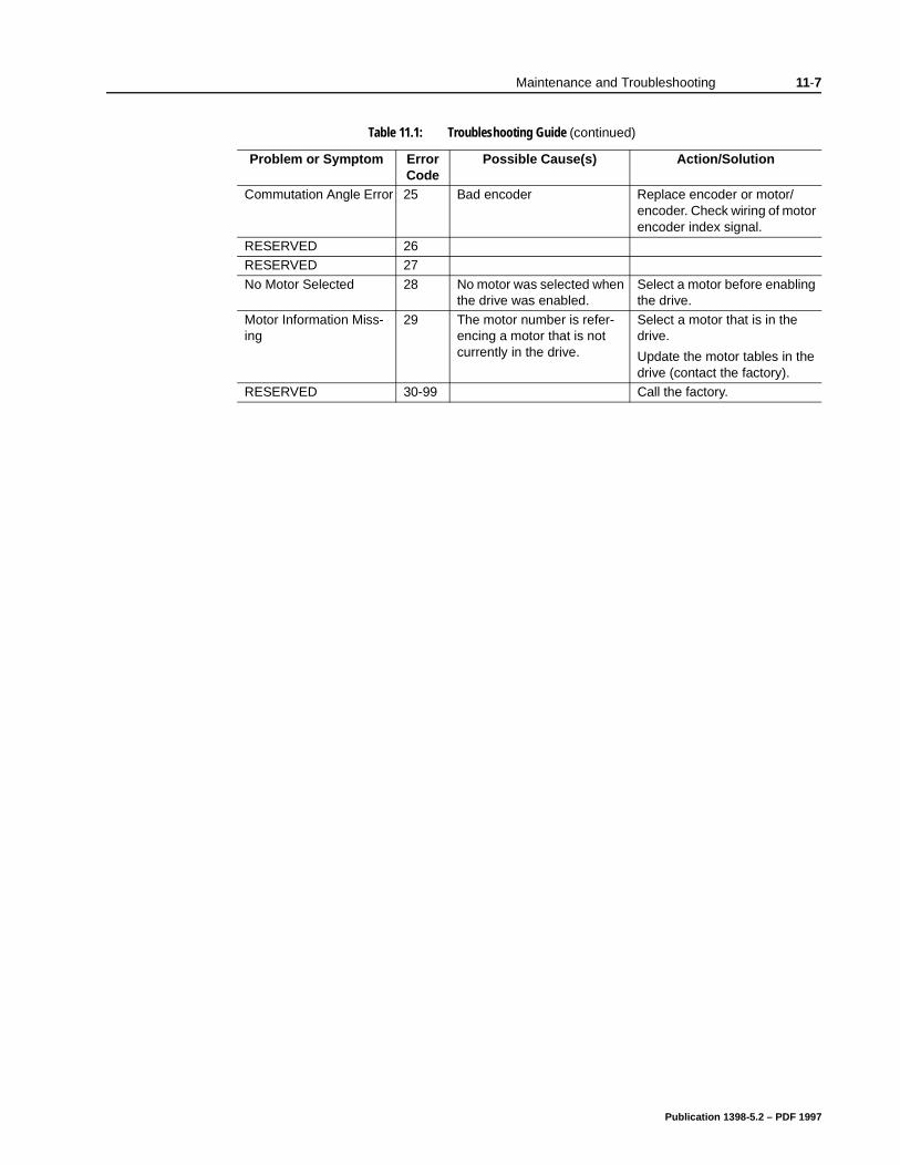
Maintenance and Troubleshooting 11-7
Commutation Angle Error 25 Bad encoder Replace encoder or motor/encoder. Check wiring of motor encoder index signal.
RESERVED 26RESERVED 27
No Motor Selected 28 No motor was selected when the drive was enabled.
Select a motor before enabling the drive.
Motor Information Miss-ing
29 The motor number is refer-encing a motor that is not currently in the drive.
Select a motor that is in the drive.
Update the motor tables in the drive (contact the factory).
RESERVED 30-99 Call the factory.
Table 11.1: Troubleshooting Guide (continued)
Problem or Symptom Error Code
Possible Cause(s) Action/Solution
Publication 1398-5.2 – PDF 1997

11-8 Maintenance and Troubleshooting
ve
ion
o
RS-232 Communication Test
This test verifies communications between an ULTRA 100 Series drive and a personal computer by connecting the XMT pin to the RCV pin. The jumper bypasses the potentially defective cable and remote unit.
Test equipment requirements are:
A PC running ULTRA Master
The Terminal mode available in Microsoft Windows.
1. Close all ULTRA Master windows.
2. Select Communication from ULTRA Master and verify your communication settings.
3. Verify the communication cable pin out and check cable continu-ity. Refer to “RS-232 Connection Diagrams” on page 6-34.
4. If the communication cable is OK, do the following:
A. Disconnect the communication cable from the drive (but leathe cable connected to the PC).
B. Jumper pins 2 and 3 on the D connector of the communicatcable.
C. Close and exit from ULTRA Master.
D. Select the Terminal from the Program Manager (Terminal isusually in the Accessories group).
E. Select Settings from the Main menu:
– Select Terminal Emulation from the drop down menu, – Choose DEC VT-100, – Choose OK to close the dialog box.
F. Select Settings from the Main menu
– Select Communications from the drop down menu– Choose COM1 (or the number of the communication port the drive is connected to) from the Connections sliding list.– Set Baud Rate to 9600– Set Data Bits to 8– Set Stop Bits to 1– Set Parity to NONE– Set Flow Control to XON/XOFF– Choose OK to close the dialog box.
5. Type any character on the keyboard. The character should echback on the screen.
Publication 1398-5.2 – PDF 1997
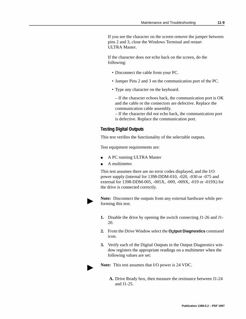
Maintenance and Troubleshooting 11-9
.
K
r
J1-
-he
-24
If you see the character on the screen remove the jumper between pins 2 and 3, close the Windows Terminal and restart ULTRA Master.
If the character does not echo back on the screen, do the following:
• Disconnect the cable from your PC.
• Jumper Pins 2 and 3 on the communication port of the PC
• Type any character on the keyboard.
– If the character echoes back, the communication port is Oand the cable or the connectors are defective. Replace thecommunication cable assembly.– If the character did not echo back, the communication portis defective. Replace the communication port.
Testing Digital Outputs
This test verifies the functionality of the selectable outputs.
Test equipment requirements are:
A PC running ULTRA Master
A multimeter.
This test assumes there are no error codes displayed, and the I/Opower supply (internal for 1398-DDM-010, -020, -030 or -075 and external for 1398-DDM-005, -005X, -009, -009X, -019 or -019X) fothe drive is connected correctly.
1. Disable the drive by opening the switch connecting J1-26 and 20.
2. From the Drive Window select the Output Diagnostics command icon.
3. Verify each of the Digital Outputs in the Output Diagnostics window registers the appropriate readings on a multimeter when tfollowing values are set:
A. Drive Ready box, then measure the resistance between J1and J1-25.
Note: Disconnect the outputs from any external hardware while per-forming this test.
Note: This test assumes that I/O power is 24 VDC.
Publication 1398-5.2 – PDF 1997
11-10 Maintenance and Troubleshooting
1-49
igh
1 -
and
and
t
– If the box is checked, the resistance should read approximately 1 Ohm.– If the box is not checked, the resistance should read veryhigh (> 1 MOhm).
B. Brake Enable box, then measure the resistance between Jand J1-50.
– If the box is checked, the resistance should read approximately 1Ohm.– If the box is not checked, the resistance should be very h(> 1 MOhm).
A load is necessary to test the transistor outputs listed below. AkOhm resistor may be connected from the transistor output (J142, J1-43, J1-44 or J1-45) to the I/O COM (J1-6).
C. Digital Output 1, then measure the voltage between J1-42 J1-13.
– If the box is checked, the voltmeter should read approximately +24 VDC.– If the box is not checked, the voltmeter should read approximately 0 VDC.
D. Digital Output 2, then measure the voltage between J1-43 J1-13.
– If the box is checked, the voltmeter should read approximately +24 VDC.– If the box is not checked, the voltmeter should read approximately 0 VDC.
4. After the test has been completed you may select Close to exiOutput Diagnostics window.
If you determine that a digital output is defective, refer to “Return Procedure” on page Help-7 to return the unit.
Publication 1398-5.2 – PDF 1997
Maintenance and Troubleshooting 11-11
Testing Digital Inputs
This test verifies the functionality of the selectable inputs.
Test equipment requirements are:
A PC running ULTRA Master
A jumper wire.
It assumes there are no error codes displayed, and the 24V power supply is connected correctly.
1. Disable the drive by opening the switch connecting J1-26 and J1-20.
2. Choose the I/O Display command icon from the Drive Window.
A. Connect J1-20 to J1-26. The Enable indicator activates.
B. Connect J1-21 to J1- 26. The Reset Faults indicator activates.
C. Connect J1-31 to J1-26. The Input 1 indicator activates.
D. Connect J1-32 to J1-26. The Input 2 indicator activates.
E. Connect J1-33 to J1-26. The Input 3 indicator activates.
3. Choose Close to exit the I/O Display window.
If you determine that a digital input is defective, please refer to “Return Procedure” on page Help-7 to return the unit for repair.
Testing Analog Output
The following tests verify the functionality of the analog outputs.
Test equipment requirements are:
A PC running ULTRA Master
A voltmeter.
Testing Analog Output 1
1. Disable the drive, by opening the connections between the ENABLE input and the I/O Power (I/O PWR).
2. Disconnect the connections to J1-31.
3. Select Output Diagnostics icon from the Drive Window.
Note: This test assumes that I/O power is 24 VDC.
Note: This test assumes that I/O power is 24 VDC.
Publication 1398-5.2 – PDF 1997
11-12 Maintenance and Troubleshooting
n
re
he
y
s
4. From the Output Diagnostics window select Analog Output 1.
5. Enter 1000 in the D/A level box.
6. Connect a DC voltmeter across analog test points J1-31 and J1-28. The meter should read approximately 1 Vdc.
7. Repeat step using different positive or negative values for the D/A Level. Verify the meter reads the values you enter.
If you determine that the output is defective, please refer to “ReturProcedure” on page Help-7 to return the unit.
Testing Analog Input
The following test verifies the functionality of the analog input.
The tests require:
a PC running ULTRA Master, and
a 10 kOhm potentiometer.
Testing the Current Limit Input
1. Verify the accuracy of the potentiometer with an ohmmeter befoinstalling.
2. Disable the drive by opening the connections between the ENABLE input and the I/O Power (I/O PWR).
3. Disconnect the connections to J1-27 and J1-28.
4. Connect the 10K potentiometer between J1-27 and J1-28. Refer to “J1 – Controller” on page 6-1 for a diagram showing tlocation of the pins.
5. Choose the Drive Signals command icon from ULTRA Master.
6. Choose Set Up, if the Drive Signals Set Up window is not alreadactive.
7. Choose Current - Input Limit + as the analog signal.
8. Choose OK to close the Set Up window and activate the Drive Signals window.
9. Slowly adjust the potentiometer while viewing the Drive Signalwindow. The Current - Input Limit + value should update as thepotentiometer is adjusted.
If you determine that the analog input is defective, refer to “ReturnProcedure” on page Help-7 to return the unit.
Note: This test assumes that I/O power is 24 VDC.
Publication 1398-5.2 – PDF 1997

Maintenance and Troubleshooting 11-13
i-
he e
Testing Encoder Inputs
The following test verifies both reception and transmission of the line count from an encoder by the drive.
The tests require:
a PC running ULTRA Master, and
a motor encoder.
Testing Encoder Inputs
1. Disable the drive by opening the connections between the ENABLE input and I/O Power (I/O PWR).
2. Choose the Drive Set Up command icon from ULTRA Master.
3. Choose Divide by 1 as the Motor Encoder Output Signal.
4. Make the following hardware connections:
• Connect the motor encoder to J2.
• Jumper the Auxiliary Encoder Inputs to the Motor EncoderOutputs by connecting the following pins:
5. Choose the Encoder Diagnostics command icon from ULTRA Master.
6. Choose Zero Count for both the Motor Encoder and Master Postion Input.
7. Slowly rotate the encoder shaft by hand while observing the counts for both the Motor Encoder and Master Position Input. TMotor Encoder and Master Position Input line counts should bequal.
If you determine that the analog input is defective, refer to “ReturnProcedure” on page Help-7 to return the unit.
Note: This test assumes that I/O power is 24 VDC.
J1-7 to J1-14 J1-10 to J1-17
J1-8 to J1-15 J1-11 to J1-18J1-9 to J1-16 J1-12 to J1-19
Publication 1398-5.2 – PDF 1997

11-14 Maintenance and Troubleshooting
Publication 1398-5.2 – PDF 1997
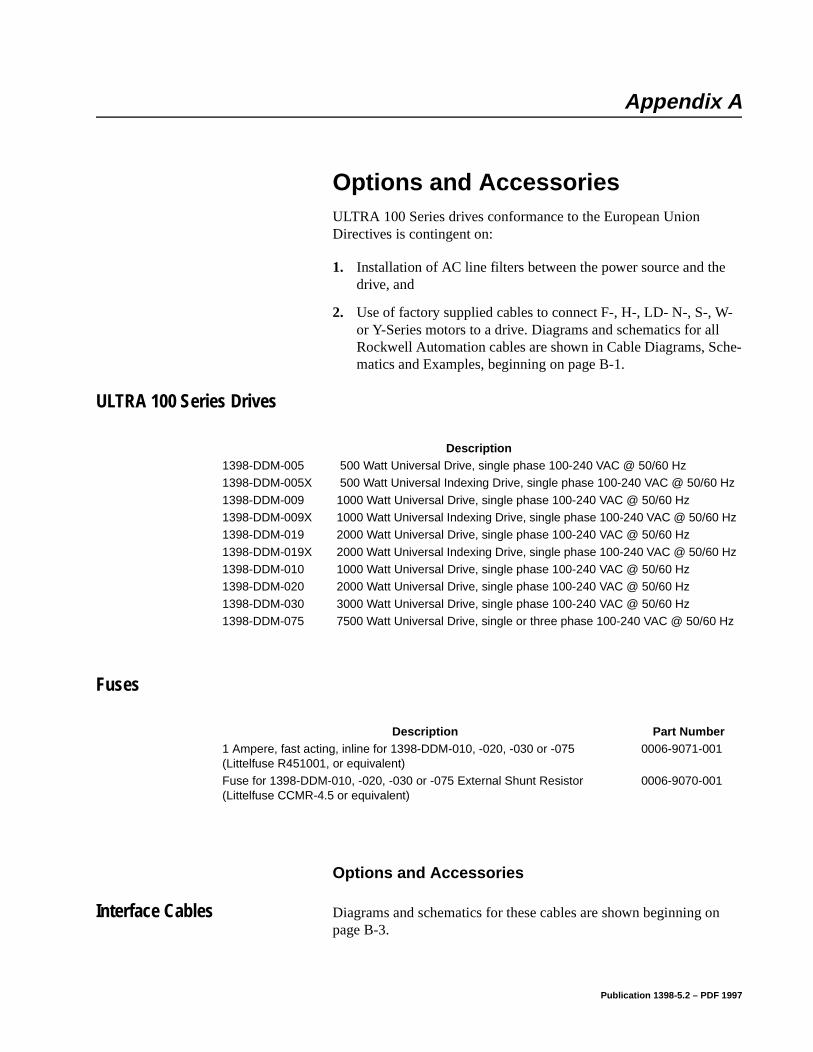
Appendix A
Options and Accessories Appendix A
ULTRA 100 Series drives conformance to the European Union Directives is contingent on:
1. Installation of AC line filters between the power source and the drive, and
2. Use of factory supplied cables to connect F-, H-, LD- N-, S-, W- or Y-Series motors to a drive. Diagrams and schematics for all Rockwell Automation cables are shown in Cable Diagrams, Sche-matics and Examples, beginning on page B-1.
ULTRA 100 Series Drives
Fuses
Options and Accessories
Interface Cables Diagrams and schematics for these cables are shown beginning on page B-3.
Description1398-DDM-005 500 Watt Universal Drive, single phase 100-240 VAC @ 50/60 Hz 1398-DDM-005X 500 Watt Universal Indexing Drive, single phase 100-240 VAC @ 50/60 Hz
1398-DDM-009 1000 Watt Universal Drive, single phase 100-240 VAC @ 50/60 Hz 1398-DDM-009X 1000 Watt Universal Indexing Drive, single phase 100-240 VAC @ 50/60 Hz 1398-DDM-019 2000 Watt Universal Drive, single phase 100-240 VAC @ 50/60 Hz
1398-DDM-019X 2000 Watt Universal Indexing Drive, single phase 100-240 VAC @ 50/60 Hz 1398-DDM-010 1000 Watt Universal Drive, single phase 100-240 VAC @ 50/60 Hz 1398-DDM-020 2000 Watt Universal Drive, single phase 100-240 VAC @ 50/60 Hz
1398-DDM-030 3000 Watt Universal Drive, single phase 100-240 VAC @ 50/60 Hz 1398-DDM-075 7500 Watt Universal Drive, single or three phase 100-240 VAC @ 50/60 Hz
Description Part Number1 Ampere, fast acting, inline for 1398-DDM-010, -020, -030 or -075(Littelfuse R451001, or equivalent)
0006-9071-001
Fuse for 1398-DDM-010, -020, -030 or -075 External Shunt Resistor (Littelfuse CCMR-4.5 or equivalent)
0006-9070-001
Publication 1398-5.2 – PDF 1997
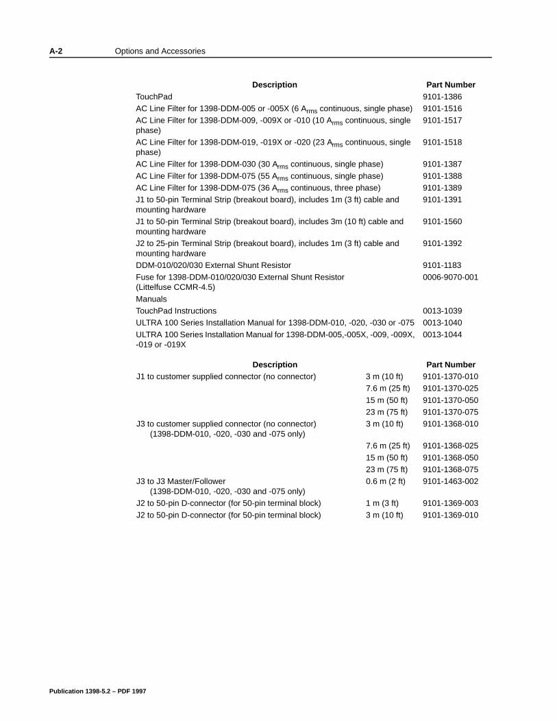
A-2 Options and Accessories
Description Part NumberTouchPad 9101-1386AC Line Filter for 1398-DDM-005 or -005X (6 Arms continuous, single phase) 9101-1516AC Line Filter for 1398-DDM-009, -009X or -010 (10 Arms continuous, single phase)
9101-1517
AC Line Filter for 1398-DDM-019, -019X or -020 (23 Arms continuous, single phase)
9101-1518
AC Line Filter for 1398-DDM-030 (30 Arms continuous, single phase) 9101-1387
AC Line Filter for 1398-DDM-075 (55 Arms continuous, single phase) 9101-1388AC Line Filter for 1398-DDM-075 (36 Arms continuous, three phase) 9101-1389J1 to 50-pin Terminal Strip (breakout board), includes 1m (3 ft) cable and mounting hardware
9101-1391
J1 to 50-pin Terminal Strip (breakout board), includes 3m (10 ft) cable and mounting hardware
9101-1560
J2 to 25-pin Terminal Strip (breakout board), includes 1m (3 ft) cable and mounting hardware
9101-1392
DDM-010/020/030 External Shunt Resistor 9101-1183
Fuse for 1398-DDM-010/020/030 External Shunt Resistor (Littelfuse CCMR-4.5)
0006-9070-001
ManualsTouchPad Instructions 0013-1039ULTRA 100 Series Installation Manual for 1398-DDM-010, -020, -030 or -075 0013-1040
ULTRA 100 Series Installation Manual for 1398-DDM-005,-005X, -009, -009X, -019 or -019X
0013-1044
Description Part NumberJ1 to customer supplied connector (no connector) 3 m (10 ft) 9101-1370-010
7.6 m (25 ft) 9101-1370-025
15 m (50 ft) 9101-1370-05023 m (75 ft) 9101-1370-075
J3 to customer supplied connector (no connector)(1398-DDM-010, -020, -030 and -075 only)
3 m (10 ft) 9101-1368-010
7.6 m (25 ft) 9101-1368-025
15 m (50 ft) 9101-1368-05023 m (75 ft) 9101-1368-075
J3 to J3 Master/Follower (1398-DDM-010, -020, -030 and -075 only)
0.6 m (2 ft) 9101-1463-002
J2 to 50-pin D-connector (for 50-pin terminal block) 1 m (3 ft) 9101-1369-003
J2 to 50-pin D-connector (for 50-pin terminal block) 3 m (10 ft) 9101-1369-010
Publication 1398-5.2 – PDF 1997
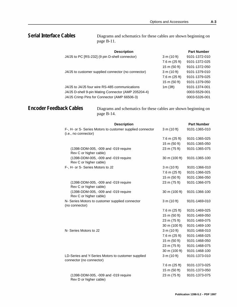
Options and Accessories A-3
Serial Interface Cables Diagrams and schematics for these cables are shown beginning on page B-11.
Encoder Feedback Cables Diagrams and schematics for these cables are shown beginning on page B-14.
Description Part NumberJ4/J5 to PC [RS-232] (9 pin D-shell connector) 3 m (10 ft) 9101-1372-010
7.6 m (25 ft) 9101-1372-025
15 m (50 ft) 9101-1372-050J4/J5 to customer supplied connector (no connector) 3 m (10 ft) 9101-1379-010
7.6 m (25 ft) 9101-1379-025
15 m (50 ft) 9101-1379-050J4/J5 to J4/J5 four wire RS-485 communications 1m (3ft) 9101-1374-001J4/J5 D-shell 9-pin Mating Connector (AMP 205204-4) 0003-5529-001
J4/J5 Crimp Pins for Connector (AMP 66506-3) 0003-5326-001
Description Part NumberF-, H- or S- Series Motors to customer supplied connector (i.e., no connector)
3 m (10 ft) 9101-1365-010
7.6 m (25 ft) 9101-1365-025
15 m (50 ft) 9101-1365-050(1398-DDM-005, -009 and -019 require Rev C or higher cable)
23 m (75 ft) 9101-1365-075
(1398-DDM-005, -009 and -019 require Rev C or higher cable)
30 m (100 ft) 9101-1365-100
F-, H- or S- Series Motors to J2 3 m (10 ft) 9101-1366-0107.6 m (25 ft) 9101-1366-025
15 m (50 ft) 9101-1366-050(1398-DDM-005, -009 and -019 require Rev C or higher cable)
23 m (75 ft) 9101-1366-075
(1398-DDM-005, -009 and -019 require Rev C or higher cable)
30 m (100 ft) 9101-1366-100
N- Series Motors to customer supplied connector (no connector)
3 m (10 ft) 9101-1469-010
7.6 m (25 ft) 9101-1469-02515 m (50 ft) 9101-1469-050
23 m (75 ft) 9101-1469-07530 m (100 ft) 9101-1469-100
N- Series Motors to J2 3 m (10 ft) 9101-1468-010
7.6 m (25 ft) 9101-1468-02515 m (50 ft) 9101-1468-05023 m (75 ft) 9101-1468-075
30 m (100 ft) 9101-1468-100LD-Series and Y-Series Motors to customer supplied connector (no connector)
3 m (10 ft) 9101-1373-010
7.6 m (25 ft) 9101-1373-02515 m (50 ft) 9101-1373-050
(1398-DDM-005, -009 and -019 require Rev D or higher cable)
23 m (75 ft) 9101-1373-075
Publication 1398-5.2 – PDF 1997
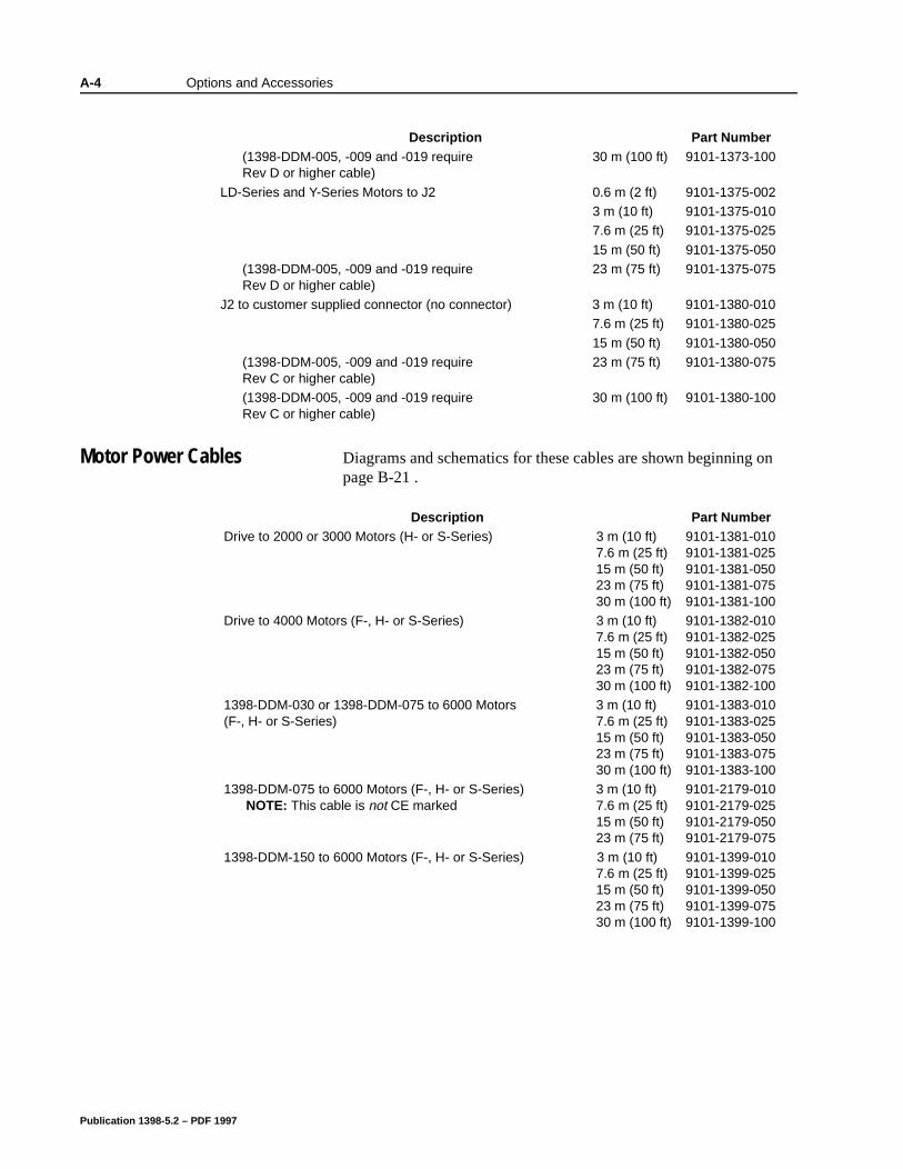
A-4 Options and Accessories
Motor Power Cables Diagrams and schematics for these cables are shown beginning on page B-21 .
(1398-DDM-005, -009 and -019 require Rev D or higher cable)
30 m (100 ft) 9101-1373-100
LD-Series and Y-Series Motors to J2 0.6 m (2 ft) 9101-1375-0023 m (10 ft) 9101-1375-0107.6 m (25 ft) 9101-1375-025
15 m (50 ft) 9101-1375-050(1398-DDM-005, -009 and -019 require Rev D or higher cable)
23 m (75 ft) 9101-1375-075
J2 to customer supplied connector (no connector) 3 m (10 ft) 9101-1380-0107.6 m (25 ft) 9101-1380-025
15 m (50 ft) 9101-1380-050(1398-DDM-005, -009 and -019 require Rev C or higher cable)
23 m (75 ft) 9101-1380-075
(1398-DDM-005, -009 and -019 require Rev C or higher cable)
30 m (100 ft) 9101-1380-100
Description Part Number
Description Part NumberDrive to 2000 or 3000 Motors (H- or S-Series) 3 m (10 ft)
7.6 m (25 ft)15 m (50 ft)23 m (75 ft)30 m (100 ft)
9101-1381-0109101-1381-0259101-1381-0509101-1381-0759101-1381-100
Drive to 4000 Motors (F-, H- or S-Series) 3 m (10 ft)7.6 m (25 ft)15 m (50 ft)23 m (75 ft)30 m (100 ft)
9101-1382-0109101-1382-0259101-1382-0509101-1382-0759101-1382-100
1398-DDM-030 or 1398-DDM-075 to 6000 Motors (F-, H- or S-Series)
3 m (10 ft)7.6 m (25 ft)15 m (50 ft)23 m (75 ft)30 m (100 ft)
9101-1383-0109101-1383-0259101-1383-0509101-1383-0759101-1383-100
1398-DDM-075 to 6000 Motors (F-, H- or S-Series)NOTE: This cable is not CE marked
3 m (10 ft)7.6 m (25 ft)15 m (50 ft)23 m (75 ft)
9101-2179-0109101-2179-0259101-2179-0509101-2179-075
1398-DDM-150 to 6000 Motors (F-, H- or S-Series) 3 m (10 ft)7.6 m (25 ft)15 m (50 ft)23 m (75 ft)30 m (100 ft)
9101-1399-0109101-1399-0259101-1399-0509101-1399-0759101-1399-100
Publication 1398-5.2 – PDF 1997
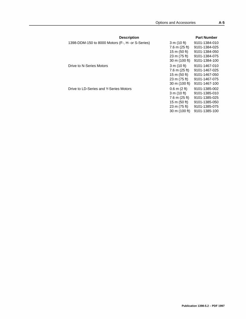
Options and Accessories A-5
1398-DDM-150 to 8000 Motors (F-, H- or S-Series) 3 m (10 ft)7.6 m (25 ft)15 m (50 ft)23 m (75 ft)30 m (100 ft)
9101-1384-0109101-1384-0259101-1384-0509101-1384-0759101-1384-100
Drive to N-Series Motors 3 m (10 ft)7.6 m (25 ft)15 m (50 ft)23 m (75 ft)30 m (100 ft)
9101-1467-0109101-1467-0259101-1467-0509101-1467-0759101-1467-100
Drive to LD-Series and Y-Series Motors 0.6 m (2 ft)3 m (10 ft)7.6 m (25 ft)15 m (50 ft)23 m (75 ft)30 m (100 ft)
9101-1385-0029101-1385-0109101-1385-0259101-1385-0509101-1385-0759101-1385-100
Description Part Number
Publication 1398-5.2 – PDF 1997
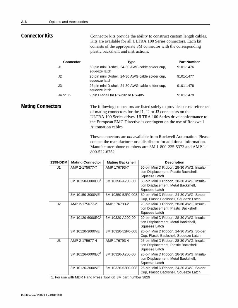
A-6 Options and Accessories
Connector Kits Connector kits provide the ability to construct custom length cables. Kits are available for all ULTRA 100 Series connectors. Each kit consists of the appropriate 3M connector with the corresponding plastic backshell, and instructions.
Mating Connectors The following connectors are listed solely to provide a cross-reference of mating connectors for the J1, J2 or J3 connectors on the ULTRA 100 Series drives. ULTRA 100 Series drive conformance to the European EMC Directive is contingent on the use of Rockwell Automation cables.
These connectors are not available from Rockwell Automation. Please contact the manufacturer or a distributor for additional information. Manufacturer phone numbers are: 3M 1-800-225-5373 and AMP 1-800-522-6752
Connector Type Part NumberJ1 50 pin mini D-shell, 24-30 AWG cable solder cup,
squeeze latch 9101-1476
J2 20 pin mini D-shell, 24-30 AWG cable solder cup, squeeze latch
9101-1477
J3 26 pin mini D-shell, 24-30 AWG cable solder cup, squeeze latch
9101-1478
J4 or J5 9 pin D-shell for RS-232 or RS-485 9101-1479
1398-DDM Mating Connector Mating Backshell DescriptionJ1 AMP 2-175677-7 AMP 176793-7 50-pin Mini D Ribbon, 28-30 AWG, Insula-
tion Displacement, Plastic Backshell, Squeeze Latch
3M 10150-6000EC1 3M 10350-A200-00 50-pin Mini D Ribbon, 28-30 AWG, Insula-tion Displacement, Metal Backshell, Squeeze Latch
3M 10150-3000VE 3M 10350-52F0-008 50-pin Mini D Ribbon, 24-30 AWG, Solder Cup, Plastic Backshell, Squeeze Latch
J2 AMP 2-175677-2 AMP 176793-2 20-pin Mini D Ribbon, 28-30 AWG, Insula-tion Displacement, Plastic Backshell, Squeeze Latch
3M 10120-6000EC1 3M 10320-A200-00 20-pin Mini D Ribbon, 28-30 AWG, Insula-tion Displacement, Metal Backshell, Squeeze Latch
3M 10120-3000VE 3M 10320-52F0-008 20-pin Mini D Ribbon, 24-30 AWG, Solder Cup, Plastic Backshell, Squeeze Latch
J3 AMP 2-175677-4 AMP 176793-4 26-pin Mini D Ribbon, 28-30 AWG, Insula-tion Displacement, Plastic Backshell, Squeeze Latch
3M 10126-6000EC1 3M 10326-A200-00 26-pin Mini D Ribbon, 28-30 AWG, Insula-tion Displacement, Metal Backshell, Squeeze Latch
3M 10126-3000VE 3M 10326-52F0-008 26-pin Mini D Ribbon, 24-30 AWG, Solder Cup, Plastic Backshell, Squeeze Latch
1. For use with MDR Hand Press Tool Kit, 3M part number 3829
Publication 1398-5.2 – PDF 1997
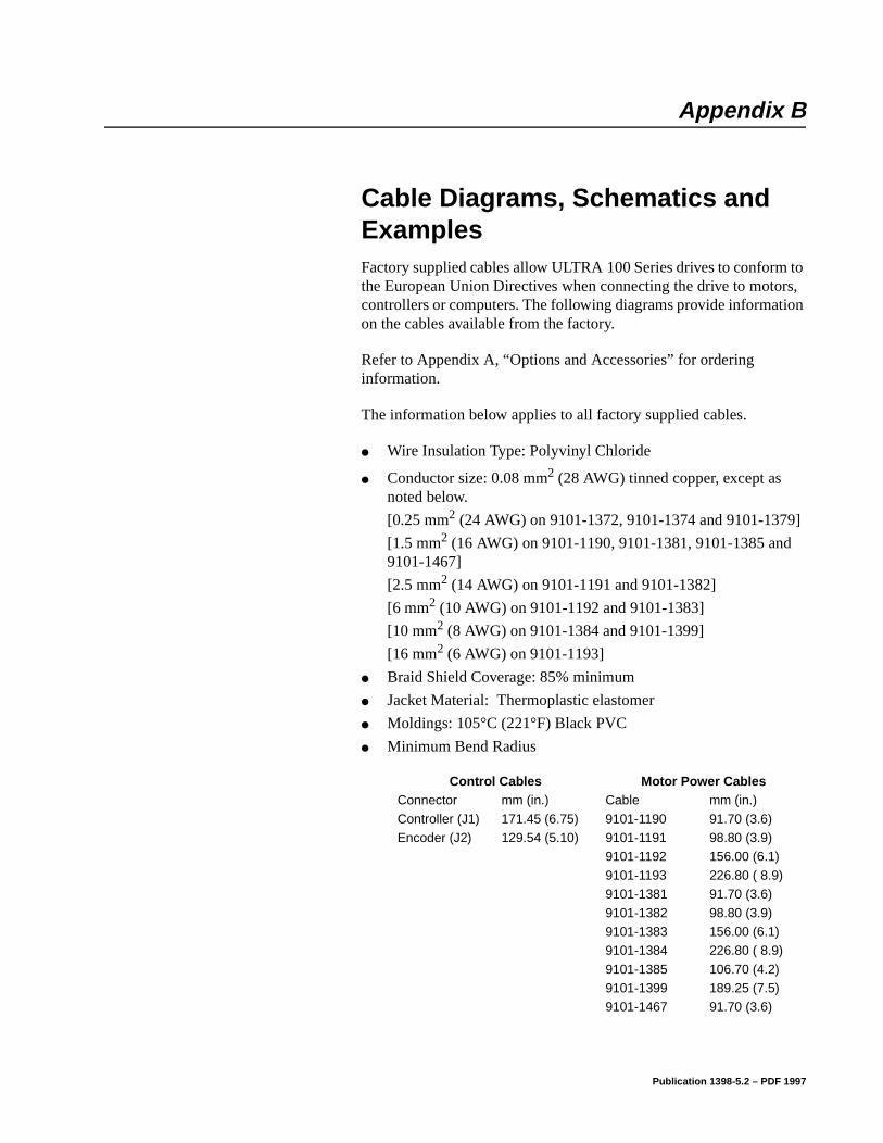
Appendix B
]
Cable Diagrams, Schematics and Examples Appendix B
Factory supplied cables allow ULTRA 100 Series drives to conform to the European Union Directives when connecting the drive to motors, controllers or computers. The following diagrams provide information on the cables available from the factory.
Refer to Appendix A, “Options and Accessories” for ordering information.
The information below applies to all factory supplied cables.
Wire Insulation Type: Polyvinyl Chloride
Conductor size: 0.08 mm2 (28 AWG) tinned copper, except as noted below.
[0.25 mm2 (24 AWG) on 9101-1372, 9101-1374 and 9101-1379
[1.5 mm2 (16 AWG) on 9101-1190, 9101-1381, 9101-1385 and9101-1467]
[2.5 mm2 (14 AWG) on 9101-1191 and 9101-1382]
[6 mm2 (10 AWG) on 9101-1192 and 9101-1383]
[10 mm2 (8 AWG) on 9101-1384 and 9101-1399]
[16 mm2 (6 AWG) on 9101-1193]
Braid Shield Coverage: 85% minimum
Jacket Material: Thermoplastic elastomer
Moldings: 105°C (221°F) Black PVC
Minimum Bend Radius
Control Cables Motor Power CablesConnector mm (in.) Cable mm (in.)
Controller (J1) 171.45 (6.75) 9101-1190 91.70 (3.6)Encoder (J2) 129.54 (5.10) 9101-1191 98.80 (3.9)
9101-1192 156.00 (6.1)
9101-1193 226.80 ( 8.9)9101-1381 91.70 (3.6)
9101-1382 98.80 (3.9)9101-1383 156.00 (6.1)9101-1384 226.80 ( 8.9)
9101-1385 106.70 (4.2)9101-1399 189.25 (7.5)9101-1467 91.70 (3.6)
Publication 1398-5.2 – PDF 1997
B-2 Cable Diagrams, Schematics and Examples
Cables are manufactured to inch dimensions. Millimeter dimensions are approximate conversions from inches.
Alternate field wiring diagram for F-, H-, or N-Series encoder cables is shown below:
Publication 1398-5.2 – PDF 1997
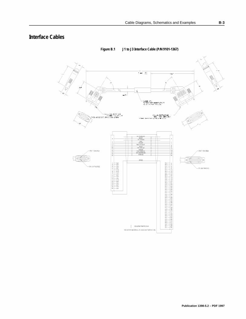
Cable Diagrams, Schematics and Examples B-3
Interface Cables
Figure B.1 J1 to J3 Interface Cable (P/N 9101-1367)Intro
0$5.(' :,7+3$57 $1' 5(9 0$18)$&785(563$57 5(9 $1' '$7( &2'(
R
R
0 [ 5(75$&7$%/(
0$&+,1(' 7+80%6&5(:
)$67(16 ',5(&7/< 72 %2$5' &211(&725
( IHHW
(
)$67(16 ',5(&7/< 72 %2$5' &211(&7250$&+,1(' 7+80%6&5(:
0 [ 5(75$&7$%/(
Publication 1398-5.2 – PDF 1997
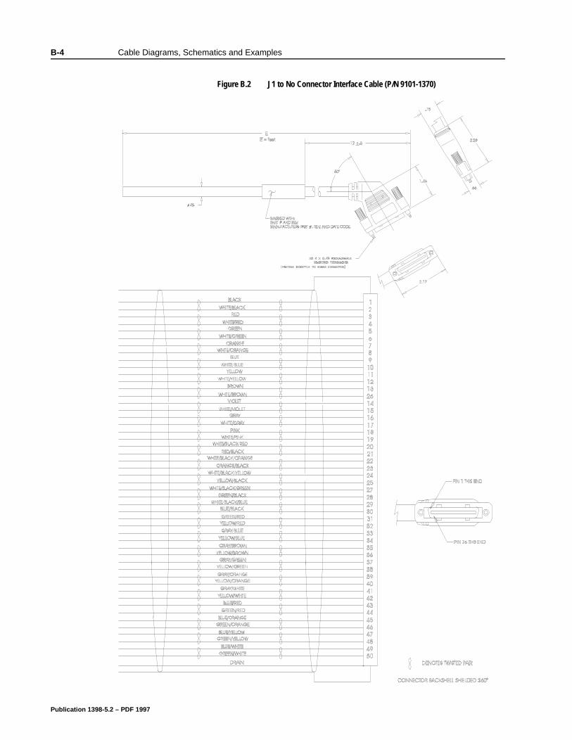
B-4 Cable Diagrams, Schematics and Examples
Figure B.2 J1 to No Connector Interface Cable (P/N 9101-1370)Intro
7$%
Publication 1398-5.2 – PDF 1997
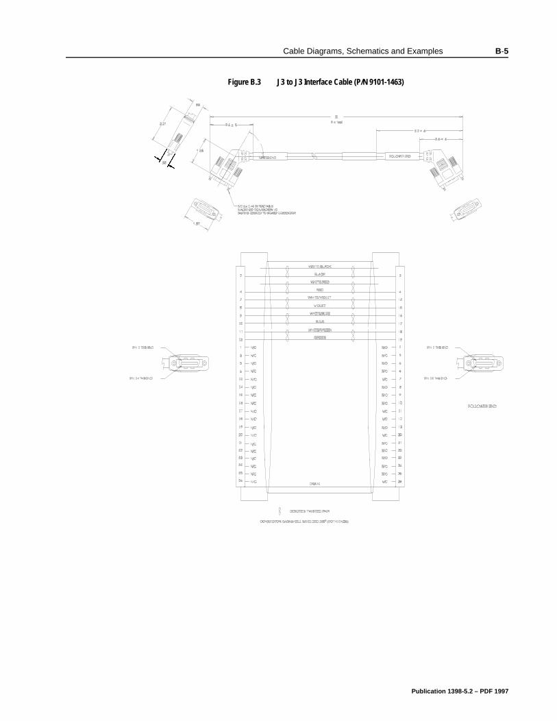
Cable Diagrams, Schematics and Examples B-5
Figure B.3 J3 to J3 Interface Cable (P/N 9101-1463)Intro
Publication 1398-5.2 – PDF 1997
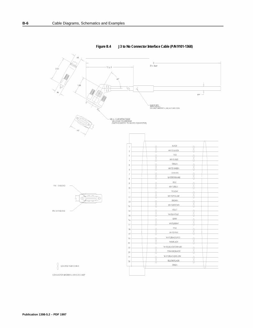
B-6 Cable Diagrams, Schematics and Examples
BCable Diagrams, Schematics and Examples
Figure B.4 J3 to No Connector Interface Cable (P/N 9101-1368)Intro
7$%
Publication 1398-5.2 – PDF 1997
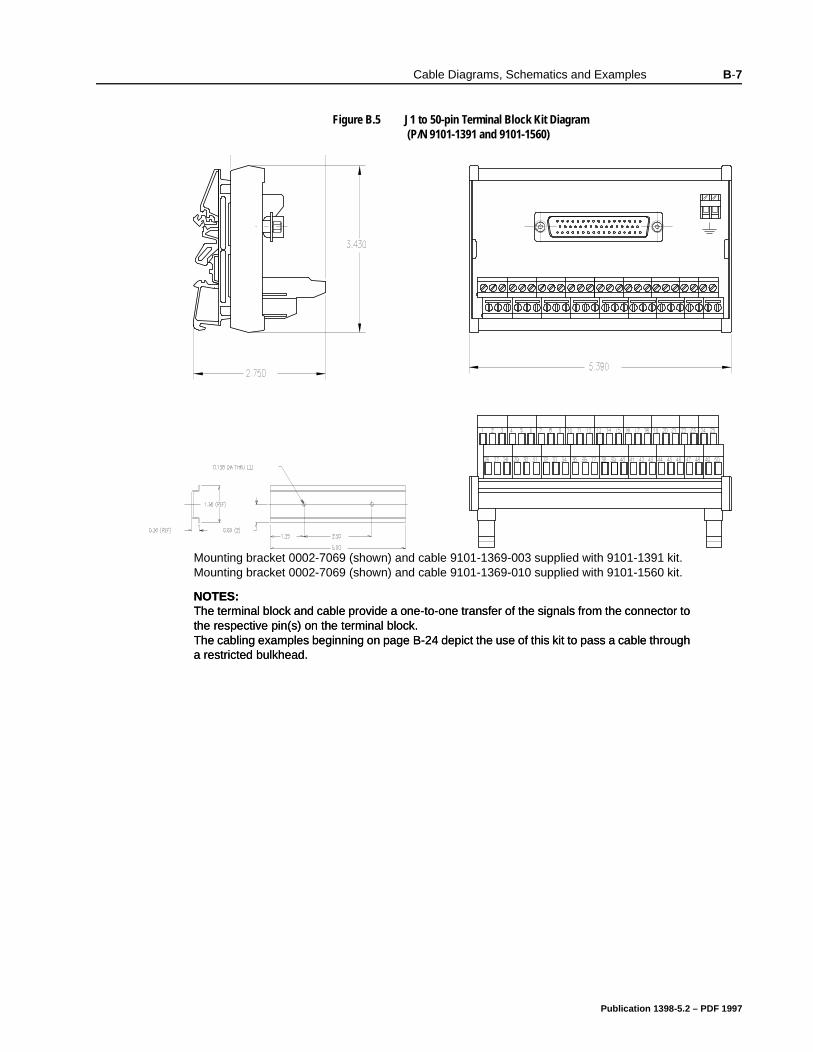
Cable Diagrams, Schematics and Examples B-7
Figure B.5 J1 to 50-pin Terminal Block Kit Diagram (P/N 9101-1391 and 9101-1560)
Intro
Mounting bracket 0002-7069 (shown) and cable 9101-1369-003 supplied with 9101-1391 kit.Mounting bracket 0002-7069 (shown) and cable 9101-1369-010 supplied with 9101-1560 kit.
NOTES: The terminal block and cable provide a one-to-one transfer of the signals from the connector to the respective pin(s) on the terminal block. The cabling examples beginning on page B-24 depict the use of this kit to pass a cable through a restricted bulkhead.
Publication 1398-5.2 – PDF 1997
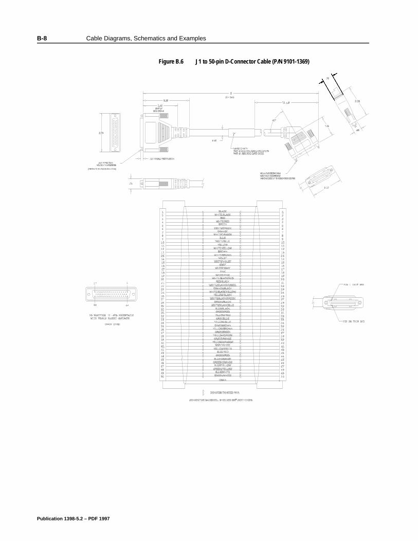
B-8 Cable Diagrams, Schematics and Examples
Figure B.6 J1 to 50-pin D-Connector Cable (P/N 9101-1369)Intro
Publication 1398-5.2 – PDF 1997
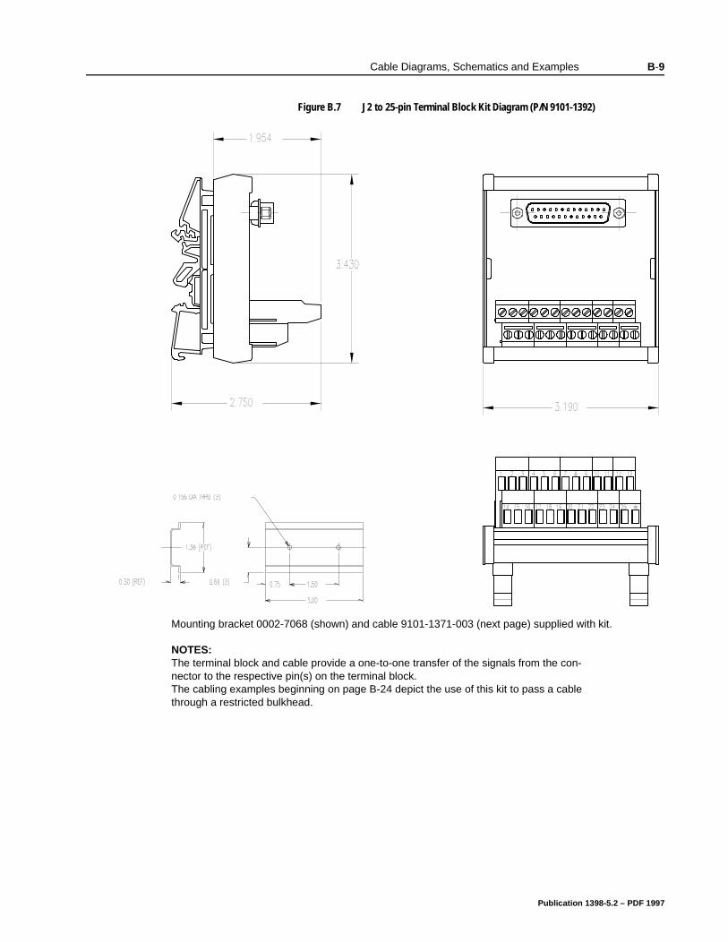
Cable Diagrams, Schematics and Examples B-9
Figure B.7 J2 to 25-pin Terminal Block Kit Diagram (P/N 9101-1392)Intro
Mounting bracket 0002-7068 (shown) and cable 9101-1371-003 (next page) supplied with kit.
NOTES: The terminal block and cable provide a one-to-one transfer of the signals from the con-nector to the respective pin(s) on the terminal block. The cabling examples beginning on page B-24 depict the use of this kit to pass a cable through a restricted bulkhead.
Publication 1398-5.2 – PDF 1997
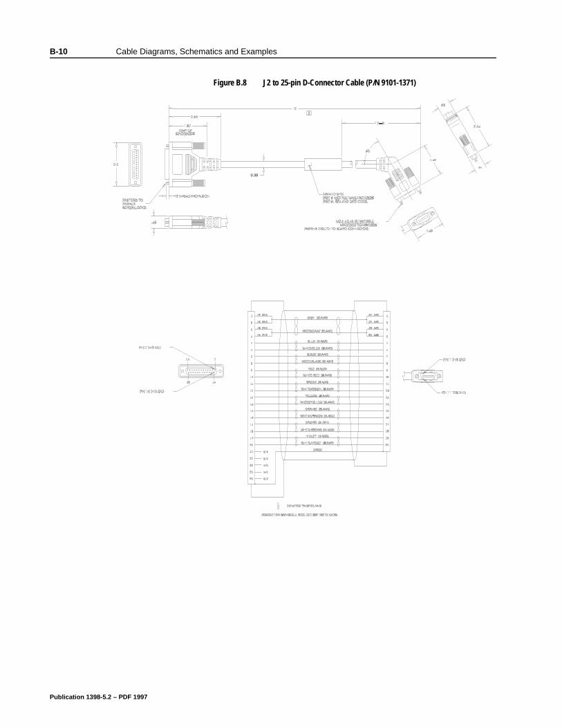
B-10 Cable Diagrams, Schematics and Examples
Figure B.8 J2 to 25-pin D-Connector Cable (P/N 9101-1371)Intro
0.38
Publication 1398-5.2 – PDF 1997
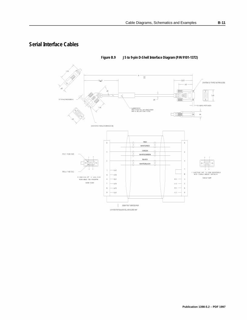
Cable Diagrams, Schematics and Examples B-11
BCable Diagrams, Schematics and Examples
Serial Interface Cables
Figure B.9 J5 to 9-pin D-Shell Interface Diagram (P/N 9101-1372)Intro
RED
GREEN
BLACK
WHITE/RED
WHITE/GREEN
WHITE/BLACK
Publication 1398-5.2 – PDF 1997
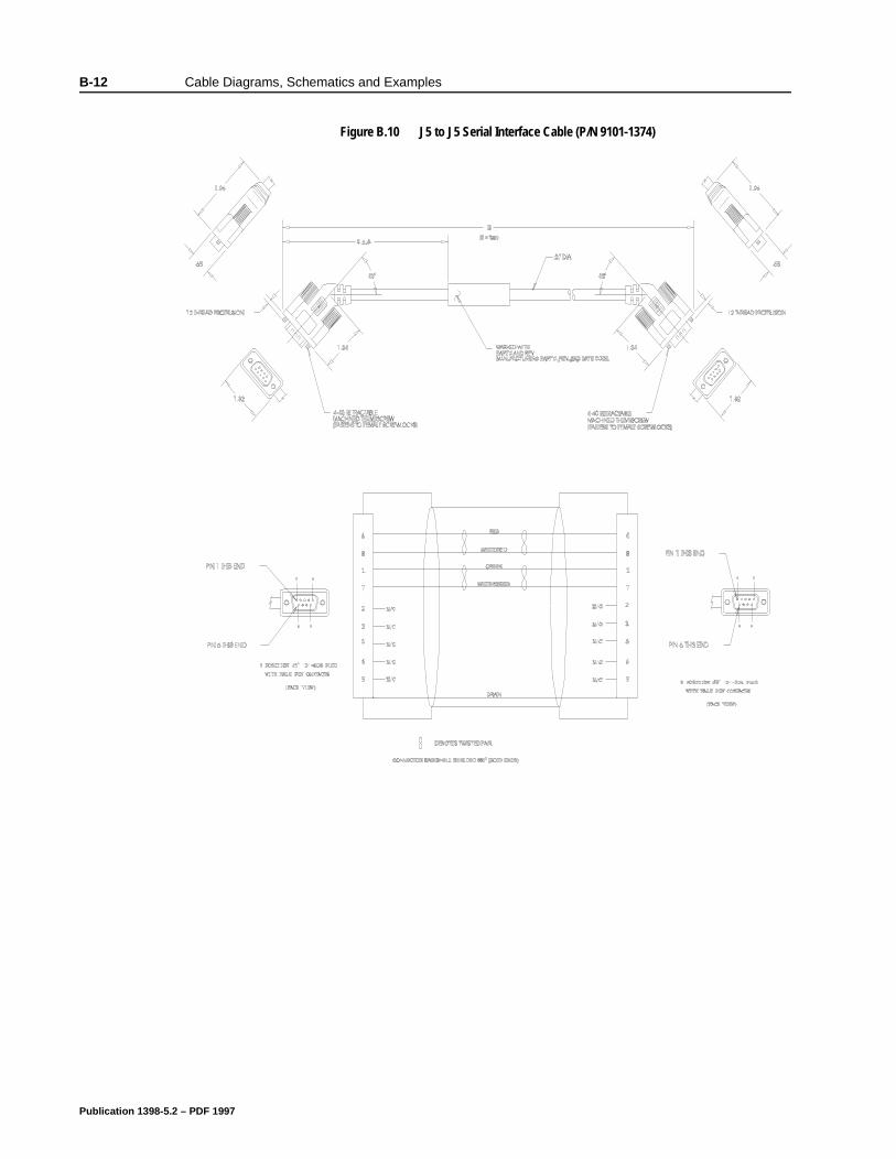
B-12 Cable Diagrams, Schematics and Examples
Figure B.10 J5 to J5 Serial Interface Cable (P/N 9101-1374)Intro
Publication 1398-5.2 – PDF 1997
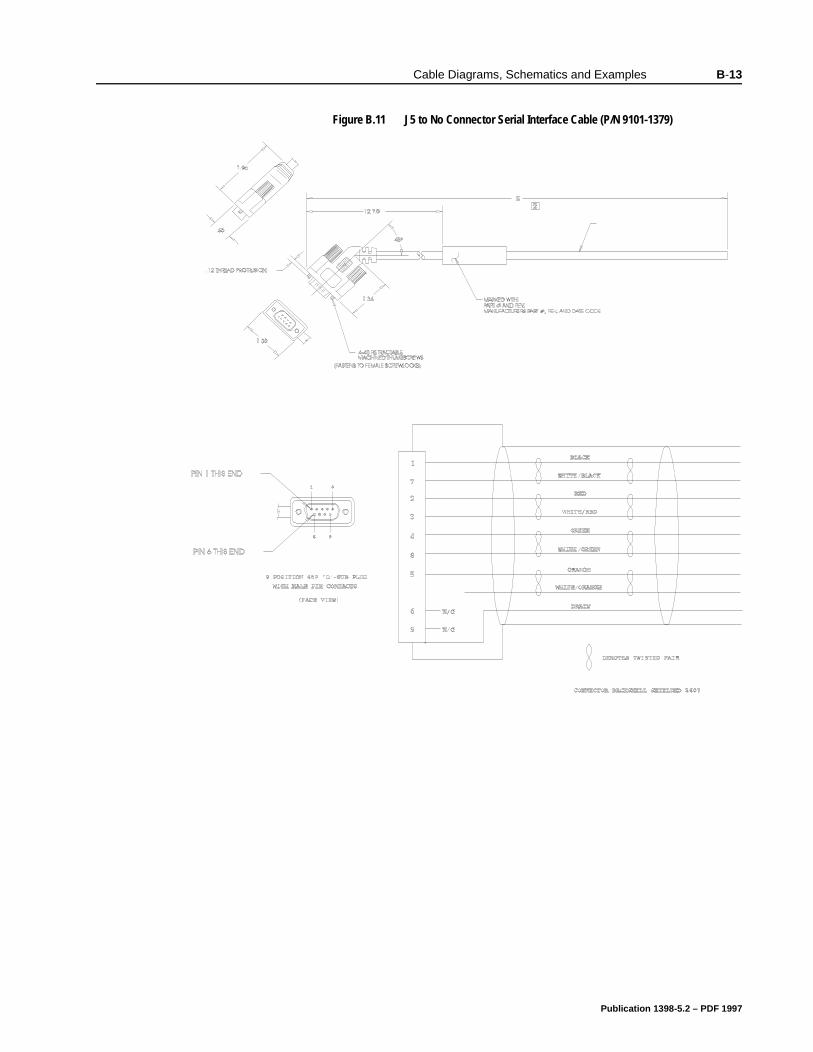
Cable Diagrams, Schematics and Examples B-13
Figure B.11 J5 to No Connector Serial Interface Cable (P/N 9101-1379)Intro
Publication 1398-5.2 – PDF 1997
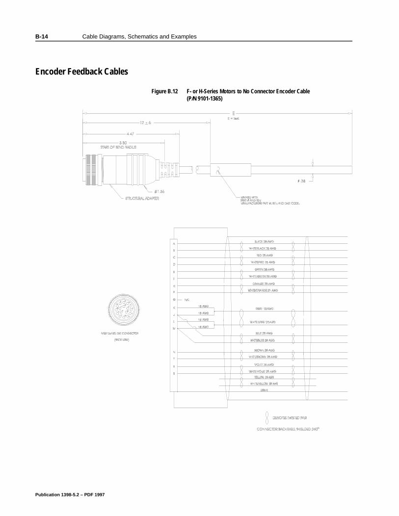
B-14 Cable Diagrams, Schematics and Examples
BCable Diagrams, Schematics and Examples
Encoder Feedback Cables
Figure B.12 F- or H-Series Motors to No Connector Encoder Cable (P/N 9101-1365)
Intro
Publication 1398-5.2 – PDF 1997
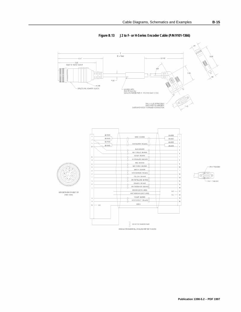
Cable Diagrams, Schematics and Examples B-15
Figure B.13 J2 to F- or H-Series Encoder Cable (P/N 9101-1366)Intro
Publication 1398-5.2 – PDF 1997
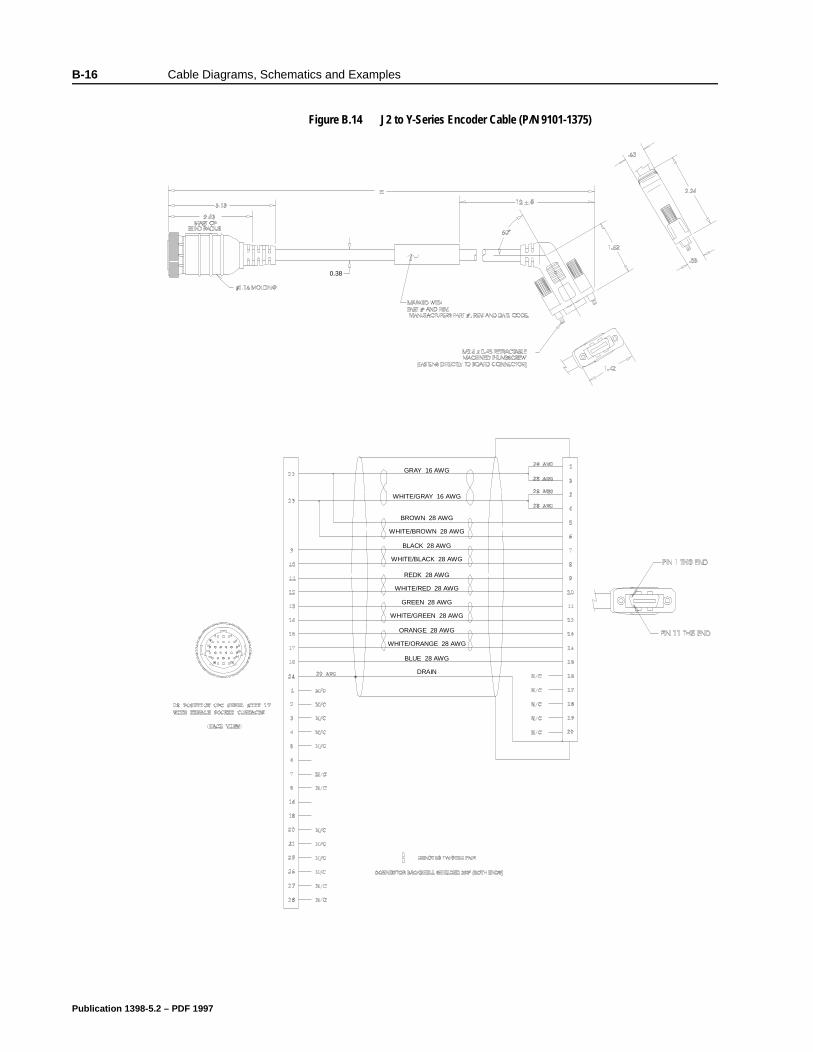
B-16 Cable Diagrams, Schematics and Examples
Figure B.14 J2 to Y-Series Encoder Cable (P/N 9101-1375)Intro
0.38
GRAY 16 AWG
WHITE/GRAY 16 AWG
WHITE/BROWN 28 AWG
BROWN 28 AWG
WHITE/BLACK 28 AWG
BLACK 28 AWG
WHITE/RED 28 AWG
REDK 28 AWG
WHITE/GREEN 28 AWG
GREEN 28 AWG
WHITE/ORANGE 28 AWG
ORANGE 28 AWG
DRAIN
BLUE 28 AWG
Publication 1398-5.2 – PDF 1997
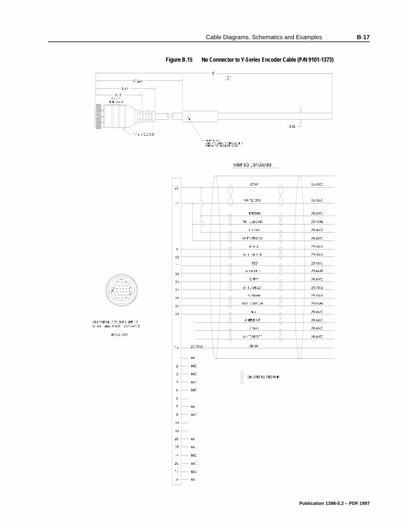
Cable Diagrams, Schematics and Examples B-17
Figure B.15 No Connector to Y-Series Encoder Cable (P/N 9101-1373)Intro
0$5.(' :,7+
3$57 $1' 5(9 0$18)$&785(56
3$57 5(9 $1' '$7( &2'(
(
%(1' 5$',86
02/',1*
67$57 2)
326,7,21 &3& 6+(// 6,=(
:,7+ )(0$/( 62&.(7 &217$&76
)$&( 9,(:
'(127(6 7:,67(' 3$,5
$:*
$:*
$:*
'5$,1
:,5,1* ',$*5$0
$:*
$:*
$:*
$:*
$:*
$:*
$:*
$:*
$:*
$:*
1&
1&
1&
1&
1&
1&
1&
1&
1&
1&
1&
1&
1&
%/8(
:+,7(25$1*(
25$1*(
:+,7(*5((1
*5((1
:+,7(5('
5('
:+,7(%/$&.
%/$&.
:+,7(%52:1
%52:1
:+,7(*5$<
*5$<
:+,7(%/8(
<(//2:
:+,7(<(//2:
9,2/(7
:+,7(9,2/(7
$:*
$:*
$:*
$:*
$:*
$:*
PART NUMBER 9101-1373-TAB
Publication 1398-5.2 – PDF 1997
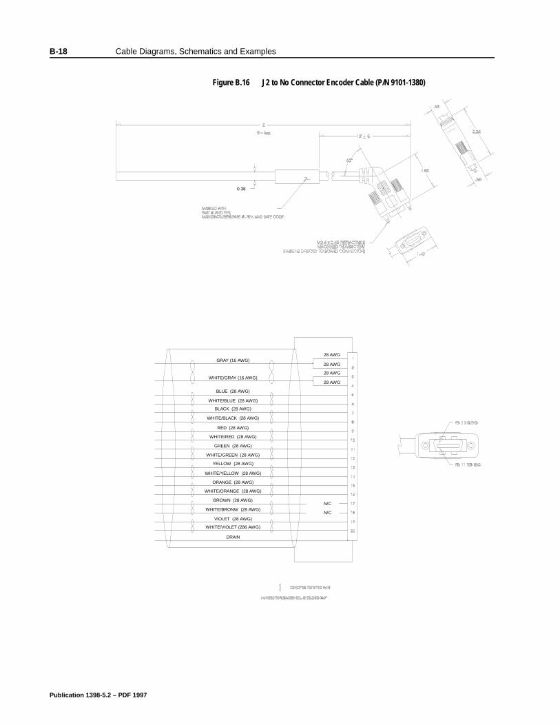
B-18 Cable Diagrams, Schematics and Examples
Figure B.16 J2 to No Connector Encoder Cable (P/N 9101-1380)Intro
0.38
WHITE/GRAY (16 AWG)
GRAY (16 AWG)
BLUE (28 AWG)
RED (28 AWG)
BLACK (28 AWG)
GREEN (28 AWG)
YELLOW (28 AWG)
ORANGE (28 AWG)
BROWN (28 AWG)
VIOLET (28 AWG)
WHITE/BLUE (28 AWG)
WHITE/BLACK (28 AWG)
WHITE/RED (28 AWG)
WHITE/GREEN (28 AWG)
WHITE/YELLOW (28 AWG)
WHITE/ORANGE (28 AWG)
WHITE/BRONW (28 AWG)
WHITE/VIOLET (286 AWG)
DRAIN
N/C
N/C
28 AWG
28 AWG
28 AWG
28 AWG
Publication 1398-5.2 – PDF 1997
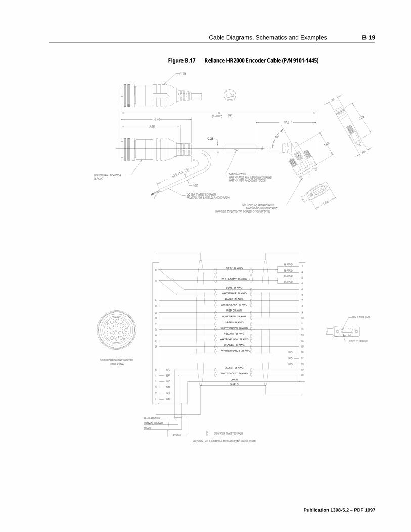
Cable Diagrams, Schematics and Examples B-19
Figure B.17 Reliance HR2000 Encoder Cable (P/N 9101-1445)Intro
0.38
WHITE/GRAY 16 AWG
GRAY 16 AWG
BLUE 28 AWG
WHITE/BLUE 28 AWG
BLACK 28 AWG
WHITE/BLACK 28 AWG
RED 28 AWG
WHITE/RED 28 AWG
GREEN 28 AWG
WHITE/GREEN 28 AWG
YELLOW 28 AWG
WHITE/YELLOW 28 AWG
ORANGE 28 AWG
WHITE/ORANGE 28 AWG
VIOLET 28 AWG
WHITE/VIOLET 28 AWG
DRAIN
SHIELD
Publication 1398-5.2 – PDF 1997
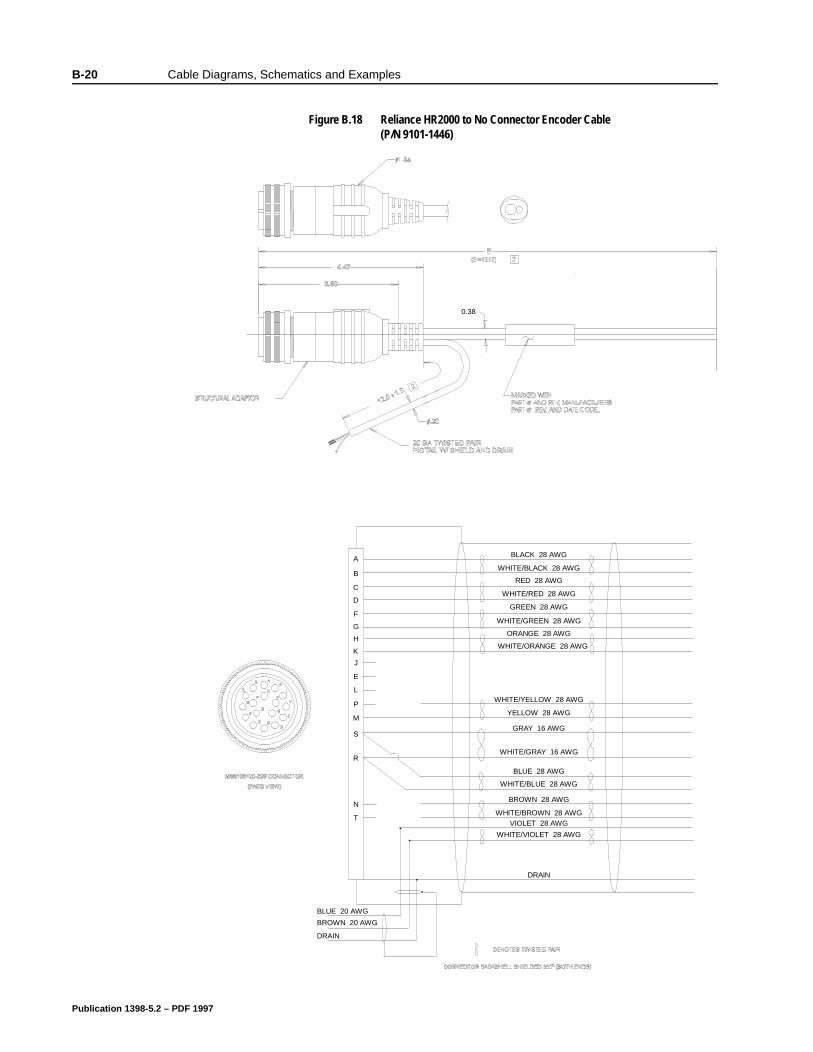
B-20 Cable Diagrams, Schematics and Examples
Figure B.18 Reliance HR2000 to No Connector Encoder Cable (P/N 9101-1446)
Intro
0.38
PART NUMBER 9101 1446 TAB
BLACK 28 AWG
WHITE/BLACK 28 AWG
RED 28 AWG
WHITE/RED 28 AWG
GREEN 28 AWG
WHITE/GREEN 28 AWG
ORANGE 28 AWG
WHITE/ORANGE 28 AWG
WHITE/YELLOW 28 AWG
YELLOW 28 AWG
GRAY 16 AWG
WHITE/GRAY 16 AWG
BLUE 28 AWG
WHITE/BLUE 28 AWG
BROWN 28 AWG
WHITE/BROWN 28 AWGVIOLET 28 AWG
WHITE/VIOLET 28 AWG
DRAIN
A
B
C
D
F
G
H
K
J
E
L
P
M
S
R
N
T
DRAIN
BROWN 20 AWG
BLUE 20 AWG
Publication 1398-5.2 – PDF 1997
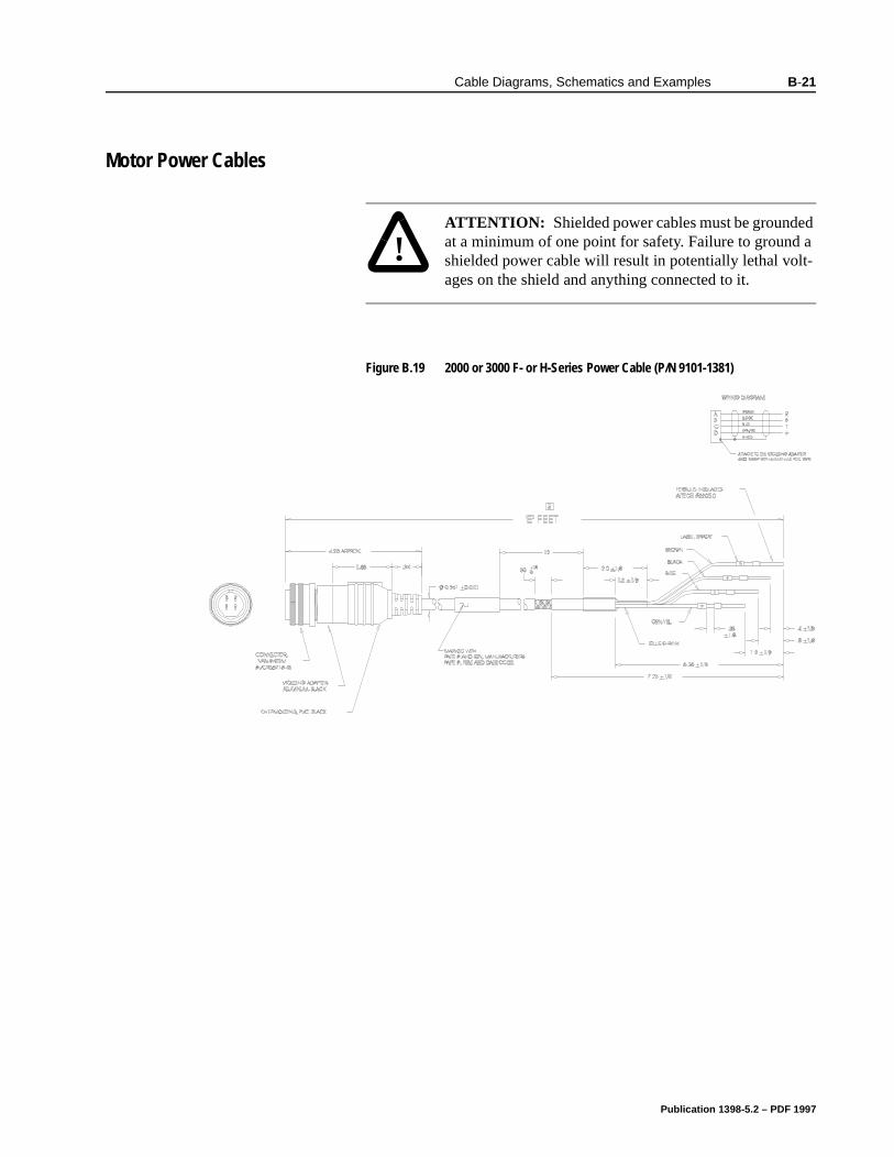
Cable Diagrams, Schematics and Examples B-21
BCable Diagrams, Schematics and Examples
Motor Power Cables
!
Intro
ATTENTION: Shielded power cables must be grounded at a minimum of one point for safety. Failure to ground a shielded power cable will result in potentially lethal volt-ages on the shield and anything connected to it.
Figure B.19 2000 or 3000 F- or H-Series Power Cable (P/N 9101-1381)Intro
Publication 1398-5.2 – PDF 1997
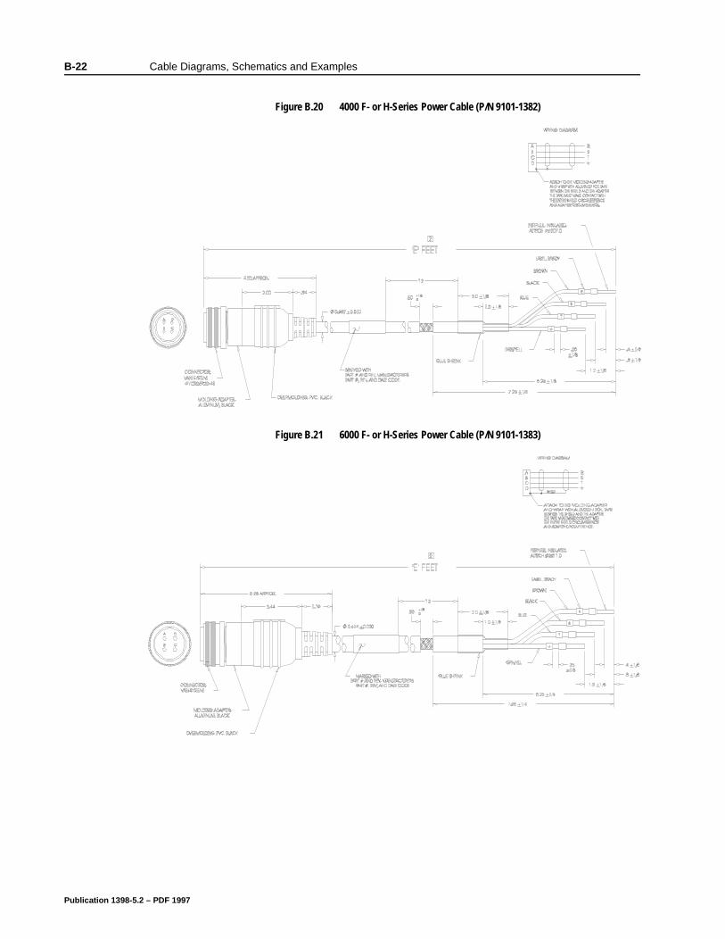
B-22 Cable Diagrams, Schematics and Examples
Figure B.20 4000 F- or H-Series Power Cable (P/N 9101-1382)Intro
Figure B.21 6000 F- or H-Series Power Cable (P/N 9101-1383)Intro
Publication 1398-5.2 – PDF 1997
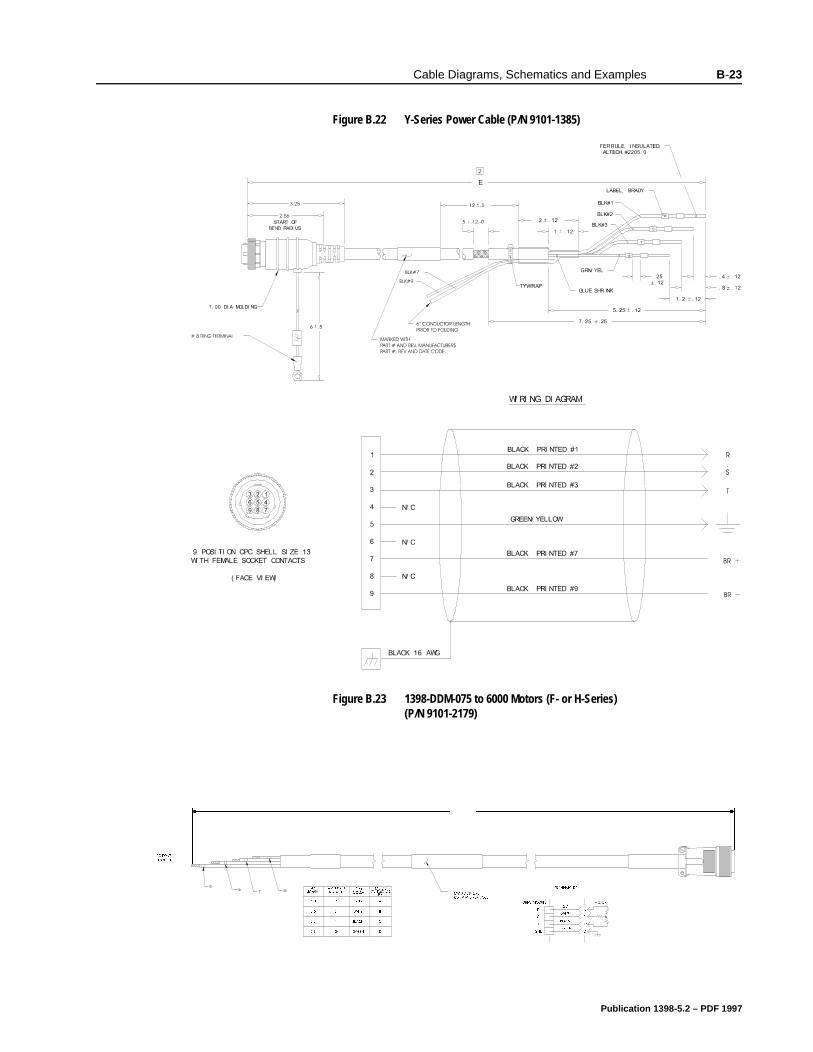
Cable Diagrams, Schematics and Examples B-23
Figure B.22 Y-Series Power Cable (P/N 9101-1385)Intro
Figure B.23 1398-DDM-075 to 6000 Motors (F- or H-Series) (P/N 9101-2179)
Intro
:,5(
/(1*7+
*
5
6
7
'5,9( 02'8/(
(1' /$%(/6
:,5(
&2/25
02725&211(&725
3,1
5('
:+,7(
%/$&.
$
%
&
*5((1 '
6&+(0$7,&
%/$&.
*1'
7
6
5
5('
:+,7(
*5((1
$
%
&
'
'5,9( 02'8/( 02725
72 '5,9(
02'8/(
0$18)$&785(56
3$57 $1' 5(9 &2'(
Publication 1398-5.2 – PDF 1997
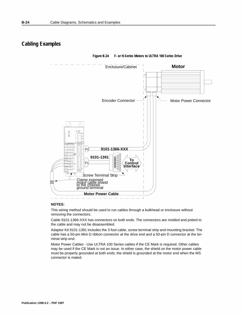
B-24 Cable Diagrams, Schematics and Examples
BCable Diagrams, Schematics and Examples
Cabling Examples
Figure B.24 F- or H-Series Motors to ULTRA 100 Series DriveIntro
Motor Power Cable
Clamp exposed to the chassis
Motor
Motor Power ConnectorEncoder Connector
P2 9101-1366-XXX
ground terminal motor cable shield
Screw Terminal Strip
Enclosure/Cabinet
P1
9101-1391To
ControlInterface
NOTES:
This wiring method should be used to run cables through a bulkhead or enclosure without removing the connectors.
Cable 9101-1366-XXX has connectors on both ends. The connectors are molded and potted to the cable and may not be disassembled.
Adaptor Kit 9101-1391 includes the 3 foot cable, screw terminal strip and mounting bracket. The cable has a 50-pin Mini D ribbon connector at the drive end and a 50-pin D connector at the ter-minal strip end.
Motor Power Cables - Use ULTRA 100 Series cables if the CE Mark is required. Other cables may be used if the CE Mark is not an issue. In either case, the shield on the motor power cable must be properly grounded at both ends; the shield is grounded at the motor end when the MS connector is mated.
Publication 1398-5.2 – PDF 1997
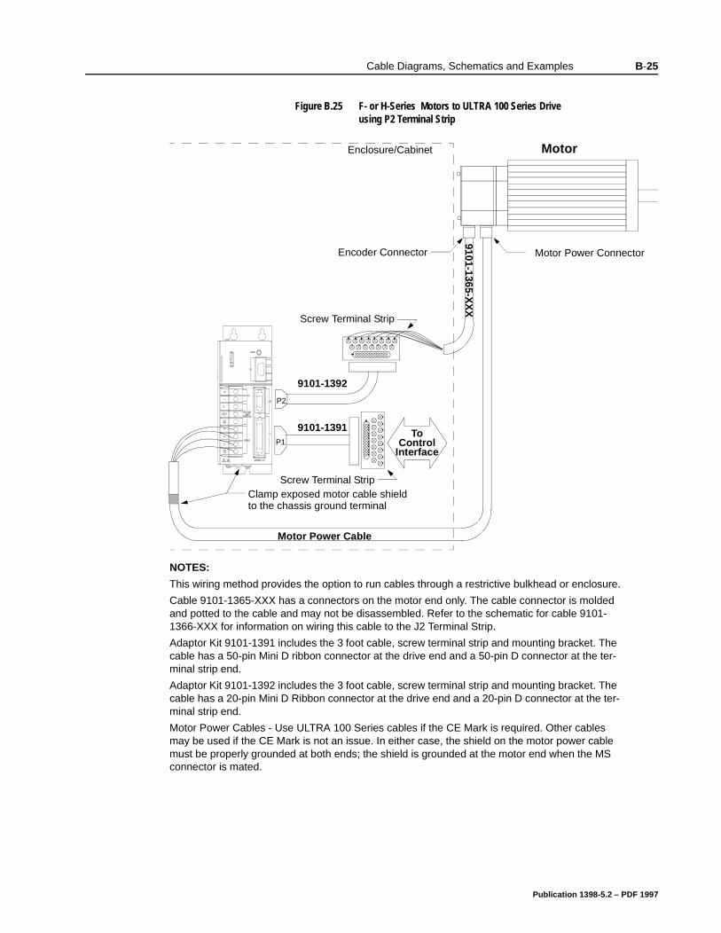
Cable Diagrams, Schematics and Examples B-25
Figure B.25 F- or H-Series Motors to ULTRA 100 Series Drive using P2 Terminal Strip
Intro
Motor Power Cable
Motor
Motor Power ConnectorEncoder Connector
P2
9101-1365-XX
X
Screw Terminal Strip
Enclosure/Cabinet
P1
9101-1391 ToControl
Interface
9101-1392
Screw Terminal Strip
NOTES:
This wiring method provides the option to run cables through a restrictive bulkhead or enclosure.
Cable 9101-1365-XXX has a connectors on the motor end only. The cable connector is molded and potted to the cable and may not be disassembled. Refer to the schematic for cable 9101-1366-XXX for information on wiring this cable to the J2 Terminal Strip.
Adaptor Kit 9101-1391 includes the 3 foot cable, screw terminal strip and mounting bracket. The cable has a 50-pin Mini D ribbon connector at the drive end and a 50-pin D connector at the ter-minal strip end.
Adaptor Kit 9101-1392 includes the 3 foot cable, screw terminal strip and mounting bracket. The cable has a 20-pin Mini D Ribbon connector at the drive end and a 20-pin D connector at the ter-minal strip end.
Motor Power Cables - Use ULTRA 100 Series cables if the CE Mark is required. Other cables may be used if the CE Mark is not an issue. In either case, the shield on the motor power cable must be properly grounded at both ends; the shield is grounded at the motor end when the MS connector is mated.
Clamp exposed motor cable shieldto the chassis ground terminal
Publication 1398-5.2 – PDF 1997
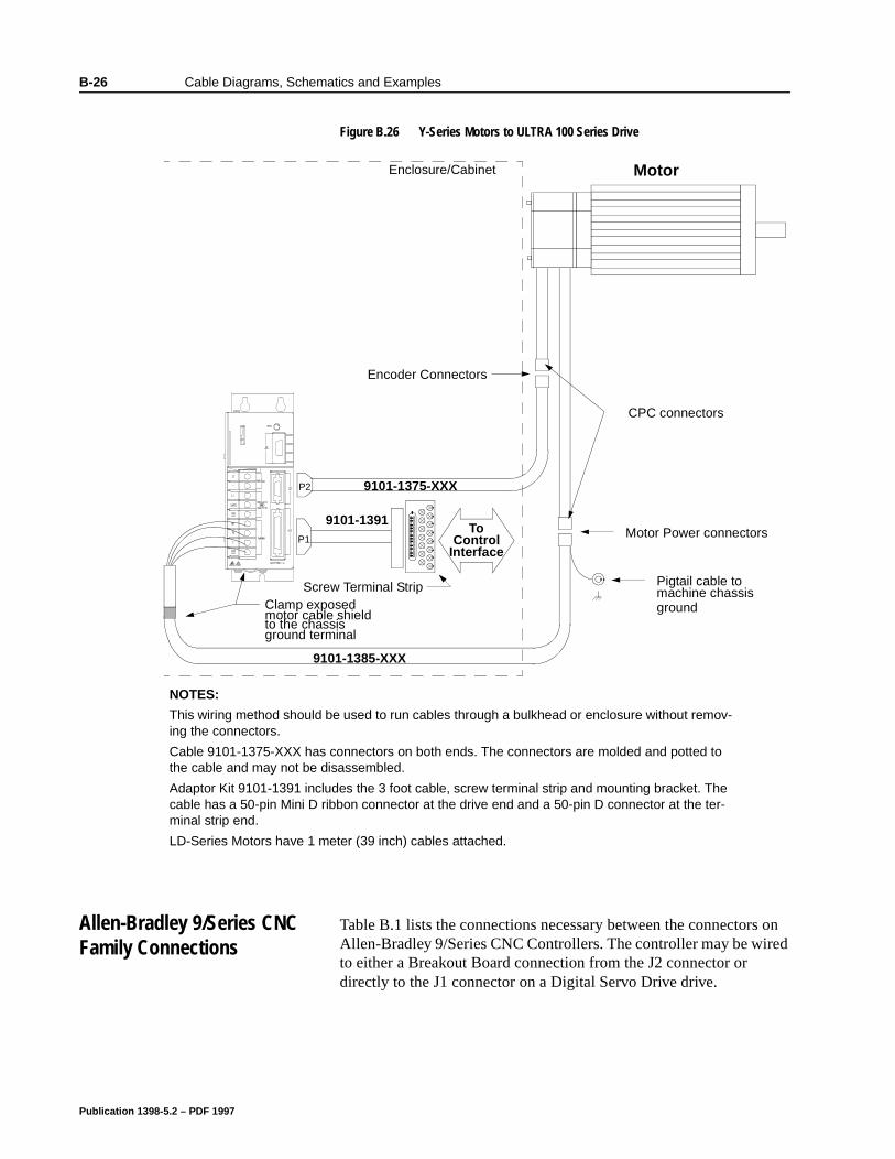
B-26 Cable Diagrams, Schematics and Examples
Allen-Bradley 9/Series CNC Family Connections
Table B.1 lists the connections necessary between the connectors on Allen-Bradley 9/Series CNC Controllers. The controller may be wired to either a Breakout Board connection from the J2 connector or directly to the J1 connector on a Digital Servo Drive drive.
Figure B.26 Y-Series Motors to ULTRA 100 Series DriveIntro
9101-1385-XXX
Clamp exposed
to the chassis
Motor
P2 9101-1375-XXX
ground terminal
motor cable shield
Screw Terminal Strip
Enclosure/Cabinet
P1
9101-1391To
ControlInterface
Motor Power connectors
Encoder Connectors
Pigtail cable to machine chassis
CPC connectors
NOTES:
This wiring method should be used to run cables through a bulkhead or enclosure without remov-ing the connectors.
Cable 9101-1375-XXX has connectors on both ends. The connectors are molded and potted to the cable and may not be disassembled.
Adaptor Kit 9101-1391 includes the 3 foot cable, screw terminal strip and mounting bracket. The cable has a 50-pin Mini D ribbon connector at the drive end and a 50-pin D connector at the ter-minal strip end.
LD-Series Motors have 1 meter (39 inch) cables attached.
ground
Publication 1398-5.2 – PDF 1997
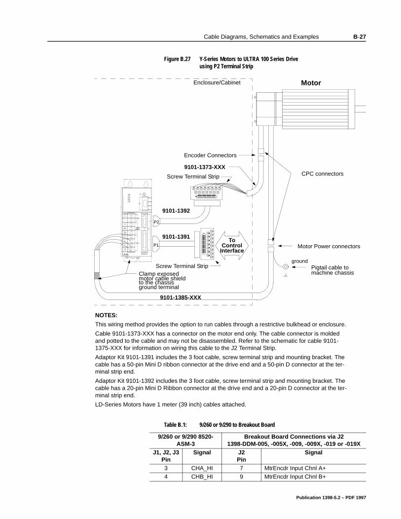
Cable Diagrams, Schematics and Examples B-27
Figure B.27 Y-Series Motors to ULTRA 100 Series Drive using P2 Terminal Strip
Intro
Table B.1: 9/260 or 9/290 to Breakout Board
9/260 or 9/290 8520-ASM-3
Breakout Board Connections via J21398-DDM-005, -005X, -009, -009X, -019 or -019X
J1, J2, J3 Pin
Signal J2Pin
Signal
3 CHA_HI 7 MtrEncdr Input Chnl A+4 CHB_HI 9 MtrEncdr Input Chnl B+
9101-1385-XXX
Clamp exposed
to the chassis
Motor
P2
ground terminal
motor cable shield
Screw Terminal Strip
Enclosure/Cabinet
P1
9101-1391To
ControlInterface
9101-1392
Screw Terminal Strip
Motor Power connectors
Encoder Connectors
9101-1373-XXX
Pigtail cable to machine chassis
CPC connectors
NOTES:
This wiring method provides the option to run cables through a restrictive bulkhead or enclosure.
Cable 9101-1373-XXX has a connector on the motor end only. The cable connector is molded and potted to the cable and may not be disassembled. Refer to the schematic for cable 9101-1375-XXX for information on wiring this cable to the J2 Terminal Strip.
Adaptor Kit 9101-1391 includes the 3 foot cable, screw terminal strip and mounting bracket. The cable has a 50-pin Mini D ribbon connector at the drive end and a 50-pin D connector at the ter-minal strip end.
Adaptor Kit 9101-1392 includes the 3 foot cable, screw terminal strip and mounting bracket. The cable has a 20-pin Mini D Ribbon connector at the drive end and a 20-pin D connector at the ter-minal strip end.
LD-Series Motors have 1 meter (39 inch) cables attached.
ground
Publication 1398-5.2 – PDF 1997
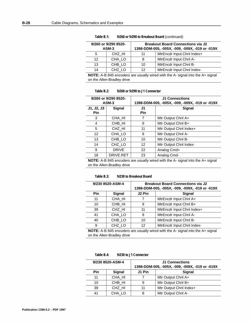
B-28 Cable Diagrams, Schematics and Examples
5 CHZ_HI 11 MtrEncdr Input Chnl Index+
12 CHA_LO 8 MtrEncdr Input Chnl A-13 CHB_LO 10 MtrEncdr Input Chnl B-14 CHZ_LO 12 MtrEncdr Input Chnl Index-
NOTE: A-B 845 encoders are usually wired with the A- signal into the A+ signal on the Allen-Bradley drive
Table B.2: 9/260 or 9/290 to J1 Connector
9/260 or 9/290 8520-ASM-3
J1 Connections1398-DDM-005, -005X, -009, -009X, -019 or -019X
J1, J2, J3Pin
Signal J1Pin
Signal
3 CHA_HI 7 Mtr Output Chnl A+4 CHB_HI 9 Mtr Output Chnl B+5 CHZ_HI 11 Mtr Output Chnl Index+
12 CHA_LO 8 Mtr Output Chnl A-13 CHB_LO 10 Mtr Output Chnl B-14 CHZ_LO 12 Mtr Output Chnl Index-
9 DRIVE 22 Analog Cmd+18 DRIVE.RET 23 Analog Cmd-
NOTE: A-B 845 encoders are usually wired with the A- signal into the A+ signal on the Allen-Bradley drive
Table B.3: 9/230 to Breakout Board
9/230 8520-ASM-4 Breakout Board Connections via J21398-DDM-005, -005X, -009, -009X, -019 or -019X
Pin Signal J2 Pin Signal11 CHA_HI 7 MtrEncdr Input Chnl A+10 CHB_HI 9 MtrEncdr Input Chnl B+39 CHZ_HI 11 MtrEncdr Input Chnl Index+
41 CHA_LO 8 MtrEncdr Input Chnl A-40 CHB_LO 10 MtrEncdr Input Chnl B-9 CHZ_LO 12 MtrEncdr Input Chnl Index-
NOTE: A-B 845 encoders are usually wired with the A- signal into the A+ signal on the Allen-Bradley drive
Table B.1: 9/260 or 9/290 to Breakout Board (continued)
9/260 or 9/290 8520-ASM-3
Breakout Board Connections via J21398-DDM-005, -005X, -009, -009X, -019 or -019X
Table B.4: 9/230 to J1 Connector
9/230 8520-ASM-4 J1 Connections1398-DDM-005, -005X, -009, -009X, -019 or -019X
Pin Signal J1 Pin Signal11 CHA_HI 7 Mtr Output Chnl A+10 CHB_HI 9 Mtr Output Chnl B+39 CHZ_HI 11 Mtr Output Chnl Index+
41 CHA_LO 8 Mtr Output Chnl A-
Publication 1398-5.2 – PDF 1997

Cable Diagrams, Schematics and Examples B-29
40 CHB_LO 10 Mtr Output Chnl B-
9 CHZ_LO 12 Mtr Output Chnl Index-NOTE: A-B 845 encoders are usually wired with the A- signal into the A+ signal on the Allen-Bradley drive
Table B.4: 9/230 to J1 Connector (continued)
9/230 8520-ASM-4 J1 Connections1398-DDM-005, -005X, -009, -009X, -019 or -019X
Publication 1398-5.2 – PDF 1997

B-30 Cable Diagrams, Schematics and Examples
Publication 1398-5.2 – PDF 1997
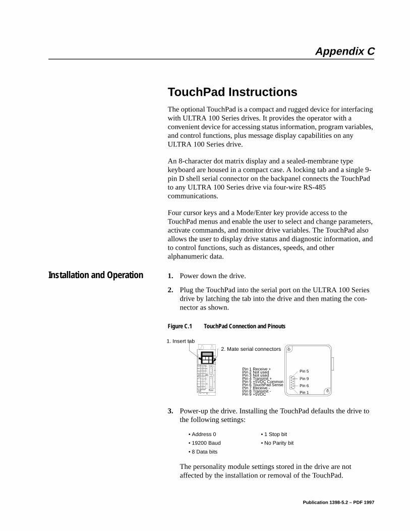
Appendix C
TouchPad Instructions Appendix C
The optional TouchPad is a compact and rugged device for interfacing with ULTRA 100 Series drives. It provides the operator with a convenient device for accessing status information, program variables, and control functions, plus message display capabilities on any ULTRA 100 Series drive.
An 8-character dot matrix display and a sealed-membrane type keyboard are housed in a compact case. A locking tab and a single 9-pin D shell serial connector on the backpanel connects the TouchPad to any ULTRA 100 Series drive via four-wire RS-485 communications.
Four cursor keys and a Mode/Enter key provide access to the TouchPad menus and enable the user to select and change parameters, activate commands, and monitor drive variables. The TouchPad also allows the user to display drive status and diagnostic information, and to control functions, such as distances, speeds, and other alphanumeric data.
Installation and Operation 1. Power down the drive.
2. Plug the TouchPad into the serial port on the ULTRA 100 Series drive by latching the tab into the drive and then mating the con-nector as shown.
3. Power-up the drive. Installing the TouchPad defaults the drive to the following settings:
The personality module settings stored in the drive are not affected by the installation or removal of the TouchPad.
Figure C.1 TouchPad Connection and PinoutsIntro
1. Insert tab
2. Mate serial connectors
Pin 9
Pin 6
Pin 1
Pin 5Pin 1Pin 2Pin 3Pin 4Pin 5Pin 6Pin 7Pin 8Pin 9
Receive +Not usedNot usedTransmit ++5VDC CommonTouchPad SenseReceive -Transmit -+5VDC
• Address 0 • 1 Stop bit
• 19200 Baud • No Parity bit
• 8 Data bits
Publication 1398-5.2 – PDF 1997
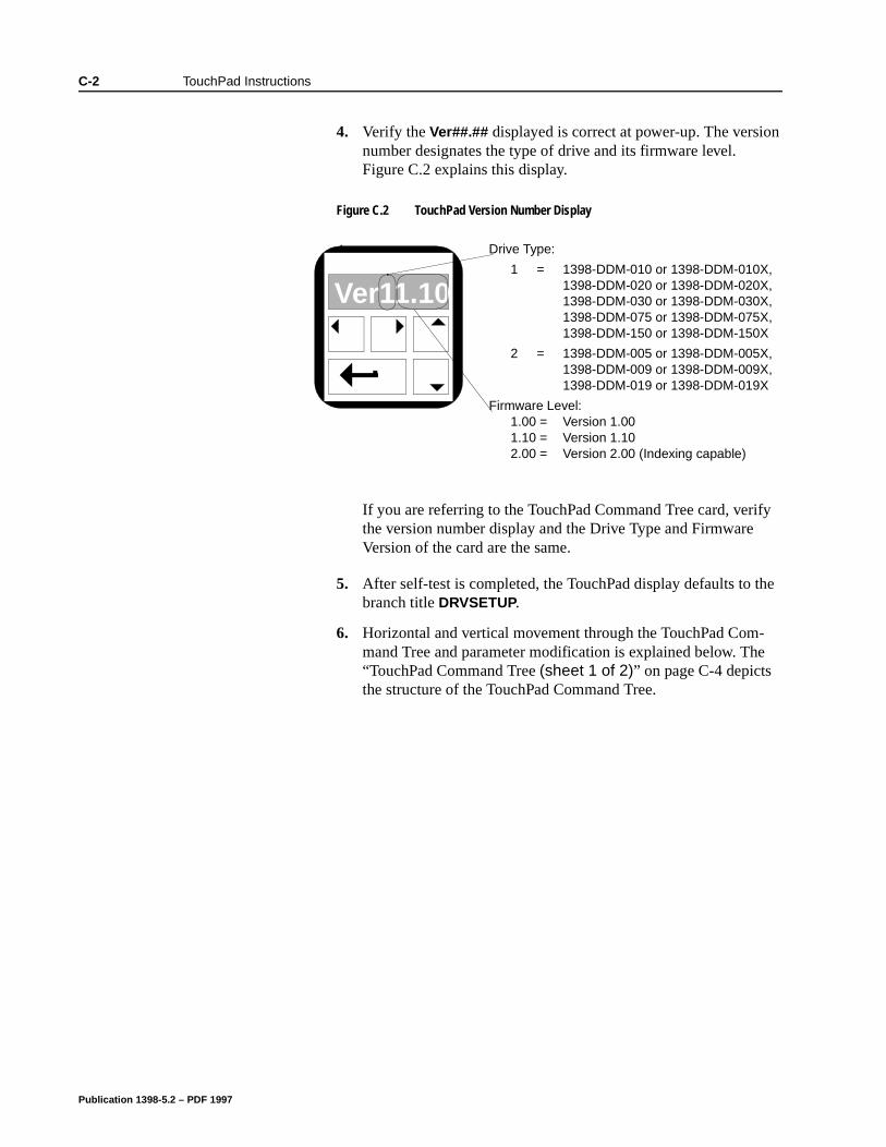
C-2 TouchPad Instructions
4. Verify the Ver##.## displayed is correct at power-up. The version number designates the type of drive and its firmware level. Figure C.2 explains this display.
If you are referring to the TouchPad Command Tree card, verify the version number display and the Drive Type and Firmware Version of the card are the same.
5. After self-test is completed, the TouchPad display defaults to the branch title DRVSETUP.
6. Horizontal and vertical movement through the TouchPad Com-mand Tree and parameter modification is explained below. The “TouchPad Command Tree (sheet 1 of 2)” on page C-4 depicts the structure of the TouchPad Command Tree.
Figure C.2 TouchPad Version Number DisplayIntro
Ver11.10
Drive Type:
1 = 1398-DDM-010 or 1398-DDM-010X, 1398-DDM-020 or 1398-DDM-020X, 1398-DDM-030 or 1398-DDM-030X, 1398-DDM-075 or 1398-DDM-075X, 1398-DDM-150 or 1398-DDM-150X
2 = 1398-DDM-005 or 1398-DDM-005X, 1398-DDM-009 or 1398-DDM-009X, 1398-DDM-019 or 1398-DDM-019X
Firmware Level:1.00 = Version 1.001.10 = Version 1.102.00 = Version 2.00 (Indexing capable)
Publication 1398-5.2 – PDF 1997
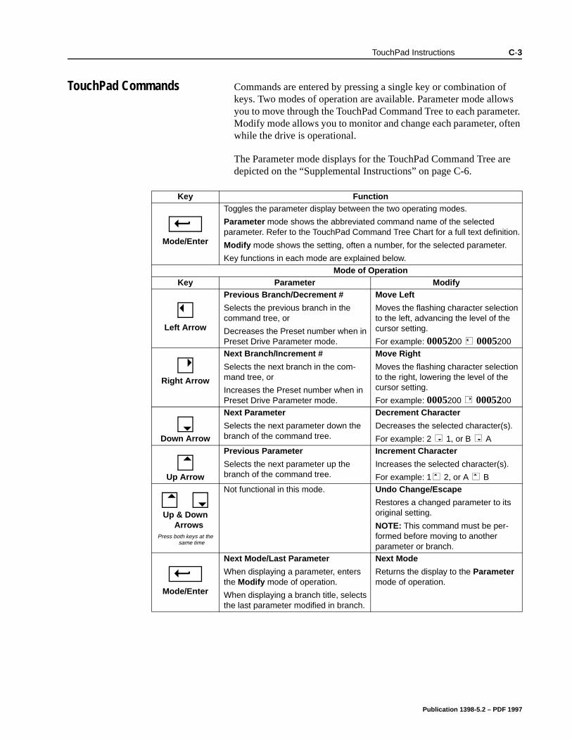
TouchPad Instructions C-3
TouchPad Commands Commands are entered by pressing a single key or combination of keys. Two modes of operation are available. Parameter mode allows you to move through the TouchPad Command Tree to each parameter. Modify mode allows you to monitor and change each parameter, often while the drive is operational.
The Parameter mode displays for the TouchPad Command Tree are depicted on the “Supplemental Instructions” on page C-6.
Key Function
Mode/Enter
Toggles the parameter display between the two operating modes.
Parameter mode shows the abbreviated command name of the selected parameter. Refer to the TouchPad Command Tree Chart for a full text definition.
Modify mode shows the setting, often a number, for the selected parameter.
Key functions in each mode are explained below.
Mode of OperationKey Parameter Modify
Left Arrow
Previous Branch/Decrement #
Selects the previous branch in the command tree, or
Decreases the Preset number when in Preset Drive Parameter mode.
Move Left
Moves the flashing character selection to the left, advancing the level of the cursor setting.
For example: 0005200 0005200
Right Arrow
Next Branch/Increment #
Selects the next branch in the com-mand tree, or
Increases the Preset number when in Preset Drive Parameter mode.
Move Right
Moves the flashing character selection to the right, lowering the level of the cursor setting.
For example: 0005200 0005200
Down Arrow
Next Parameter
Selects the next parameter down the branch of the command tree.
Decrement Character
Decreases the selected character(s).
For example: 2 1, or B A
Up Arrow
Previous Parameter
Selects the next parameter up the branch of the command tree.
Increment Character
Increases the selected character(s).
For example: 1 2, or A B
Up & Down Arrows
Press both keys at the same time
Not functional in this mode. Undo Change/Escape
Restores a changed parameter to its original setting.
NOTE: This command must be per-formed before moving to another parameter or branch.
Mode/Enter
Next Mode/Last Parameter
When displaying a parameter, enters the Modify mode of operation.
When displaying a branch title, selects the last parameter modified in branch.
Next Mode
Returns the display to the Parameter mode of operation.
Publication 1398-5.2 – PDF 1997
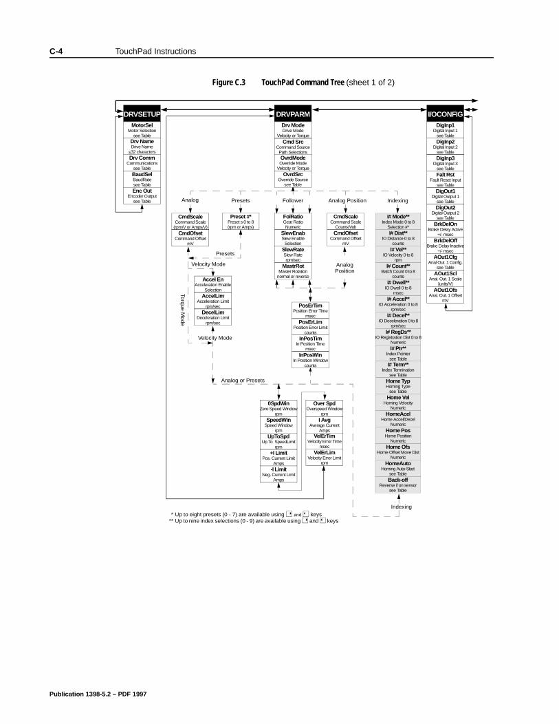
C-4 TouchPad Instructions
Figure C.3 TouchPad Command Tree (sheet 1 of 2)
FolRatioGear RatioNumeric
SlewEnabSlew Enable
SelectionSlewRateSlew Raterpm/sec
MastrRotMaster Rotation
normal or reverse
DRVSETUPMotorSel
Motor Selectionsee Table
Drv NameDrive Name
<32 charactersDrv Comm
Communicationssee TableBaudSelBaudRatesee TableEnc Out
Encoder Outputsee Table
DRVPARMDrv ModeDrive Mode
Velocity or Torque
CmdScaleCommand Scale
(rpm/V or Amps/V)CmdOfset
Command OffsetmV
I/OCONFIGDigInp1
Digital Input 1see TableDigInp2
Digital Input 2see TableDigInp3
Digital Input 3see Table
DigOut1Digital Output 1
see TableDigOut2
Digital Output 2see TablePreset #*
Preset s 0 to 8(rpm or Amps)
Accel EnAcceleration Enable
SelectionAccelLim
Acceleration Limitrpm/sec
DecelLimDeceleration Limit
rpm/sec
Presets
Velocity Mode
Torque Mode
Velocity Mode
Analog or Presets
0SpdWinZero Speed Window
rpmSpeedWin
Speed Windowrpm
UpToSpdUp To SpeedLimit
rpm+I Limit
Pos. Current LimitAmps
-I LimitNeg. Current Limit
Amps
BrkDelOnBrake Delay Active
+/- msecBrkDelOff
Brake Delay Inactive+/- msec
AOut1CfgAnal Out. 1 Config.
see TableAOut1Scl
Anal. Out. 1 Scale[units/V]
AOut1OfsAnal. Out. 1 Offset
mV
Cmd SrcCommand Source
Path Selections
I# Dist**IO Distance 0 to 8
countsI# Vel**
IO Velocity 0 to 8rpm
I# Count**Batch Count 0 to 8
countsI# Dwell**
IO Dwell 0 to 8msec
I# Accel**IO Acceleration 0 to 8
rpm/secI# Decel**
IO Deceleration 0 to 8rpm/sec
I# RegDs**IO Registration Dist 0 to 8
Numeric
VelErTimVelocity Error Time
msecVelErLim
Velocity Error Limitrpm
Over SpdOverspeed Window
rpmI Avg
Average CurrentAmps
I# Mode**Index Mode 0 to 8
Selection #*
PresetsAnalog Indexing
CmdScaleCommand Scale
Counts/Volt
PosErTimPosition Error Time
msecPosErLim
Position Error Limitcounts
InPosTimIn Position Time
msecInPosWin
In Position Windowcounts
Analog Position
OvrdModeOverride Mode
Velocity or TorqueOvrdSrc
Override Sourcesee Table
AnalogPosition
I# Ptr**Index Pointer
see TableI# Term**
Index Terminationsee Table
Home TypHoming Type
see TableHome Vel
Homing VelocityNumeric
HomeAcelHome Accel/Decel
NumericHome PosHome Position
NumericHome Ofs
Home Offset Move DistNumeric
HomeAutoHoming Auto-Start
see Table
Falt RstFault Reset Input
see Table
Back-offReverse if on sensor
see Table
* Up to eight presets (0 - 7) are available using and keys ** Up to nine index selections (0 - 9) are available using and keys
Follower
CmdOfsetCommand Offset
mV
Indexing
Publication 1398-5.2 – PDF 1997
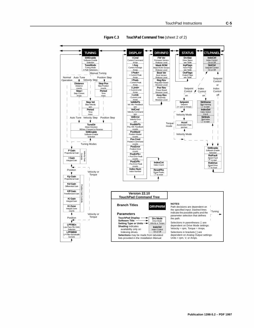
TouchPad Instructions C-5
Figure C.3 TouchPad Command Tree (sheet 2 of 2)
CTLPANELSTATUSDrvStat
Drive Statussee TableInpFlagsInput Flagssee Table
OutFlagsOutput Flags
see Table
DRVINFOFW Ver
Firmware VersionRelease LevelMask ROM
Mask ROM VersionRelease Level
Reg RevRegulator BoardRevision Level
Pwr RevPower Board
Revision LevelAssy RevAssembly
Revision Level
DISPLAYI Cmd
Current CommandAmpsI Avg
Current AverageAmps
I Peak++ Current Peak
AmpsI Peak-
- Current PeakAmps
I Limit++ Current Limit
AmpsI Limit-
- Current LimitAmps
TUNINGSWEnable
Software EnableSelection
TuneModeTuning Mode
4 Path Selections
DistanceDistancecountsStep I
Step CurrentAmps
Step PosStep Position
countsPeriod
Timemsec
Step VelStep Velocity
rpmPeriod
Timemsec
P GainProportional Gain
I GainIntegral Gain
Kp GainProportional Gain
Kd GainDifferential Gain
Kff GainFeedforward Gain
Ki GainIntegral Gain
Ki ZoneIntegral Zone
counts
LPFiltEnLow Pass Fltr. Enbl.
SelectionLPFiltBW
LP Filter Bandwidthnumeric
SWEnableSoftware Enable
Selection
VelMtrFbVel. Mtr. Feedback
rpmVelCmd
Velocity Commandrpm
VelErrorVelocity Error
rpmPosMtrFb
Pos. Mtr. Feedbackcounts
PosMastrPosition Master
countsPos Cmd
Position Commandcounts
PosErrorPosition Error
countsPosErPk+
+ Pos Error Peakcounts
PosErPk-- Pos Error Peak
counts
ResetPksReset Peaks
to reset
Velocity Gain
Position G
ain Controls
Manual Tuning
Position StepVelocity Step
Auto TuneNormalOperation
Position StepVelocity StepAuto Tune
Tuning Modes
Velocity orTorque
Velocity orTorque
TuneDirMotor Direction
BiDirec, Forward or Reverse
Controls
Boot VerBoot Version
Release Level
Index NumIndex Number
IndexCntIndex Count
SetpointSetpoint
(+/- rpm or Amps)
AccelAcceleration Rate
rpm/sec
SWErableSoftware Enable
Selection
StrtCtrlSetpoint Control
On or Off
IndxCtrlIndex Control
On or Off
StrtHomeStart Homing
to startIndexSelIndex Select
0 to 8StrtIndxStart index
to start
RstFaultReset Fault
to startRstDriveReset Drive
to reset
Torquemode
SetpointControl
IndexControl
Velocity Mode
Velocity Mode
SetpointControl
orIndexControl
offon on
Position
Position
IndxCtrlIndex Control
On or Off
Version 22.10TouchPad Command Tree
DRVPARM
Drv ModeDrive Mode
Velocity or Torque
Branch Titles
ParametersTouchPad DisplaySoftware TitleSetting Type or Units
NOTES:
Shading indicates availability only on Indexing drives.
Selections may be made from tabulated lists provided in the Installation Manual.
Selections in brackets [ ] are dependent on Analog Output settings: Units = rpm, V, or Amps.
Selections in parentheses ( ) are dependent on Drive Mode settings: Velocity = rpm, Torque = Amps.
Path decisions are dependent on the specified input. Dashed lines indicate the possible paths and the parameter selection that defines the path.
Tuning
Publication 1398-5.2 – PDF 1997
C-6 TouchPad Instructions
Supplemental Instructions
Motor Selection
Enter a Motor Identification number to load the correct motor parameters into the drive. Table C.2 on page C-11 and Table C.3 on page C-13 list the motors available in the motor table directory. Selection of a motor defines default operating parameters for the drive and motor combination.
Analog Output Scaling
Selection of Analog Output Scaling through the TouchPad requires manual input of the scaling parameters. To calculate the necessary scaling parameters, first determine the Command Source (Analog or Preset/Follower). If Analog is the Command source, then determine the Drive Mode (Velocity or Torque).
Depending on the Command Source/Drive Mode, calculate the scaling information to be input at the Analog Output Scaling display as follows:
Analog in Velocity Mode
1. Divide the desired velocity scale (rpm) by the maximum motor speed (rpm) and multiply that value by 16383.
Analog in Torque Mode
1. Divide the desired current scale by the lesser of the following:
• Motor Continuous Current (Amps) times 3, or
• Drive Rated Current (Amps)
2. Multiply that value by 8191.
Preset/Follower
1. Enter the desired position (in counts).
Publication 1398-5.2 – PDF 1997
TouchPad Instructions C-7
Displays
Text
A drive name longer than eight characters may require scrolling with the Left, , and Right, , arrow keys. Drive names may be up to 32 characters in length.
Flashing characters in the Modify mode display are the characters that are active.
Change the cursor position and resolution using the and keys. For example: If the Drv Name in the Modify mode displays InFeed with the F flashing, pressing the key causes the first e to flash.
Press the or keys to increment or decrement a character by scrolling through the list of valid ASCII characters. For example, If the Drv Name in the Modify mode displays InFfed with the lowercase f is flashing, pressing the key causes the flashing character to decrement to e.
Numeric
Flashing characters in the Modify mode display are the numbers that are active.
Change the cursor position and resolution using the or key. For example: If the Over Spd in the Modify mode displays 5200 and 52 is flashing, pressing the key causes 520 to flash.
Press the or key to increment or decrement these numbers. For example: If the Over Spd value is 5200 and 52 is flashing, pressing the key causes the setting to increment by 100 rpm each time the key is pressed.
Parameter values may not exceed the maximum or minimum limits, regardless of the cursor position. For example: If the SpeedWin setting is 5000 rpm and the Maximum Speed in the motor table is 5200, pressing the key increases the parameter to 5200 (the upper limit), but pressing the
key decrements the parameter to 4000.
The most significant digit is reserved when a parameter allows a negative (-) setting or the parameter provides a list of possible selections. The or key toggles the minus sign.
List
The most significant digit is reserved for an active/inactive selection marker when a parameter provides a list of possible selections.
Publication 1398-5.2 – PDF 1997
C-8 TouchPad Instructions
19 ns. m
l
at d.
e-
he
yed
pes
A filled arrow, , in the most significant digit indicates the active setting from a list of possible settings. Inactive settings are indicated by a unfilled arrow, . For example: If the drive is functioning as Preset Controller in the Velocity mode, pressing the key from DRVPARAM scrolls through the CmdSrc list which includes Presets, AuxEnc, StepDir, StepU/D, and Analog.
The Mode/Enter, , key selects a parameter from the list.
List selections that are undefined are indicated by Unknown. This display indicates the TouchPad data table is incompatible with the drive.
Lists are associated with all parameters, except DISPLAY and DRVINFO. Refer to the tables beginning on page C-16 for the items in each list. Table C.17, “Drive Status List for TouchPad” on page C-is a read-only list, all other lists contain possible parameter selectioAfter an option is selected, the display reverts to the parameter frowhich the option was selected. For example: Selection of the EncAlign parameter under STATUS provides the options Normaand Align. Selection of either option returns you to the EncAligndisplay.
Ratio
A FolRatio (gear ratio) longer than eight characters may require scrolling with the and keys. The ratios are numeric values thincrement or decrement by 1 each time the , or , key is presse
The method of display is dependent on the length of the ratios:
If the ratio is eight characters or less, the complete ratio is displayed. For example, a Master to Follower ratio of one-thousand to ninhundred is displayed as 1000:900.
If the ratio requires more than eight characters the ratio is displayed in two parts: a Master Ratio and a Follower Ratio. Tposition of the colon (:) after or before each numeric value indicates Master or Follower for these larger ratios. The and keys toggle between the Master Ratio and the Follower Ratio. For example: A Master to Follower ratio on 1001:1000 is displayed in two separate displays. The Master Ratio is displaas 1001: and pressing displays the Follower Ratio :1000.
Fault/Error/Warning
C.1lists the possible fault, error and warning messages that may appear on the TouchPad. The items below describe the different tyof messages.
Publication 1398-5.2 – PDF 1997
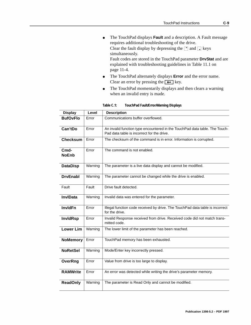
TouchPad Instructions C-9
The TouchPad displays Fault and a description. A Fault message requires additional troubleshooting of the drive. Clear the fault display by depressing the and keys simultaneously. Fault codes are stored in the TouchPad parameter DrvStat and are explained with troubleshooting guidelines in Table 11.1 on page 11-4.
The TouchPad alternately displays Error and the error name. Clear an error by pressing the key.
The TouchPad momentarily displays and then clears a warning when an invalid entry is made.
Table C.1: TouchPad Fault/Error/Warning Displays
Display Level Description
BufOvFlo Error Communications buffer overflowed.
Can’tDo Error An invalid function type encountered in the TouchPad data table. The Touch-Pad data table is incorrect for the drive.
Checksum Error The checksum of the command is in error. Information is corrupted.
Cmd-NoEnb
Error The command is not enabled.
DataDisp Warning The parameter is a live data display and cannot be modified.
DrvEnabl Warning The parameter cannot be changed while the drive is enabled.
Fault Fault Drive fault detected.
InvlData Warning Invalid data was entered for the parameter.
InvldFn Error Illegal function code received by drive. The TouchPad data table is incorrect for the drive.
InvldRsp Error Invalid Response received from drive. Received code did not match trans-mitted code.
Lower Lim Warning The lower limit of the parameter has been reached.
NoMemory Error TouchPad memory has been exhausted.
NoRetSel Warning Mode/Enter key incorrectly pressed.
OverRng Error Value from drive is too large to display.
RAMWrite Error An error was detected while writing the drive’s parameter memory.
ReadOnly Warning The parameter is Read Only and cannot be modified.
Publication 1398-5.2 – PDF 1997
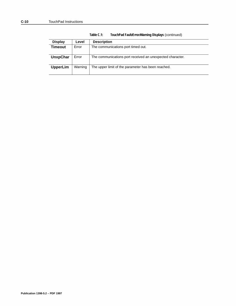
C-10 TouchPad Instructions
Timeout Error The communications port timed out.
UnxpChar Error The communications port received an unexpected character.
UpperLim Warning The upper limit of the parameter has been reached.
Table C.1: TouchPad Fault/Error/Warning Displays (continued)
Display Level Description
Publication 1398-5.2 – PDF 1997
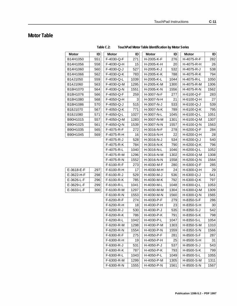
TouchPad Instructions C-11
Motor Table
Table C.2: TouchPad Motor Table Identification by Motor Series
Motor ID Motor ID Motor ID Motor IDB14H1050 551 F-4030-Q-F 271 H-2005-K-F 276 H-4075-R-F 282
B14H1056 558 F-4030-Q-H 15 H-2005-K-H 20 H-4075-R-H 26B14H1060 560 F-4030-Q-J 527 H-2005-K-J 532 H-4075-R-J 538B14H1066 562 F-4030-Q-K 783 H-2005-K-K 788 H-4075-R-K 794
B14J1050 559 F-4030-Q-L 1039 H-2005-K-L 1044 H-4075-R-L 1050B14J1060 563 F-4030-Q-M 1295 H-2005-K-M 1300 H-4075-R-M 1306B18H1070 564 F-4030-Q-N 1551 H-2005-K-N 1556 H-4075-R-N 1562
B18H1076 566 F-4050-Q-F 259 H-3007-N-F 277 H-6100-Q-F 283B18H1080 568 F-4050-Q-H 3 H-3007-N-H 21 H-6100-Q-H 27B18H1086 570 F-4050-Q-J 515 H-3007-N-J 533 H-6100-Q-J 539
B18J1070 567 F-4050-Q-K 771 H-3007-N-K 789 H-6100-Q-K 795B18J1080 571 F-4050-Q-L 1027 H-3007-N-L 1045 H-6100-Q-L 1051B90H1015 557 F-4050-Q-M 1283 H-3007-N-M 1301 H-6100-Q-M 1307
B90H1025 561 F-4050-Q-N 1539 H-3007-N-N 1557 H-6100-Q-N 1563B90H1035 565 F-4075-R-F 272 H-3016-N-F 278 H-6200-Q-F 284B90H1045 569 F-4075-R-H 16 H-3016-N-H 22 H-6200-Q-H 28
F-4075-R-J 528 H-3016-N-J 534 H-6200-Q-J 540F-4075-R-K 784 H-3016-N-K 790 H-6200-Q-K 796F-4075-R-L 1040 H-3016-N-L 1046 H-6200-Q-L 1052
F-4075-R-M 1296 H-3016-N-M 1302 H-6200-Q-M 1308F-4075-R-N 1552 H-3016-N-N 1558 H-6200-Q-N 1564F-6100-R-F 273 H-4030-M-F 280 H-6300-Q-F 285
E-3618-E-F 297 F-6100-R-H 17 H-4030-M-H 24 H-6300-Q-H 29E-3622-H-F 298 F-6100-R-J 529 H-4030-M-J 536 H-6300-Q-J 541E-3626-L-F 296 F-6100-R-K 785 H-4030-M-K 792 H-6300-Q-K 797
E-3629-L-F 299 F-6100-R-L 1041 H-4030-M-L 1048 H-6300-Q-L 1053E-3633-L-F 300 F-6100-R-M 1297 H-4030-M-M 1304 H-6300-Q-M 1309
F-6100-R-N 1553 H-4030-M-N 1560 H-6300-Q-N 1565
F-6200-R-F 274 H-4030-P-F 279 H-8350-S-F 286F-6200-R-H 18 H-4030-P-H 23 H-8350-S-H 30F-6200-R-J 530 H-4030-P-J 535 H-8350-S-J 542
F-6200-R-K 786 H-4030-P-K 791 H-8350-S-K 798F-6200-R-L 1042 H-4030-P-L 1047 H-8350-S-L 1054F-6200-R-M 1298 H-4030-P-M 1303 H-8350-S-M 1310
F-6200-R-N 1554 H-4030-P-N 1559 H-8350-S-N 1566F-6300-R-F 275 H-4050-P-F 281 H-8500-S-F 287F-6300-R-H 19 H-4050-P-H 25 H-8500-S-H 31
F-6300-R-J 531 H-4050-P-J 537 H-8500-S-J 543F-6300-R-K 787 H-4050-P-K 793 H-8500-S-K 799F-6300-R-L 1043 H-4050-P-L 1049 H-8500-S-L 1055
F-6300-R-M 1299 H-4050-P-M 1305 H-8500-S-M 1311F-6300-R-N 1555 H-4050-P-N 1561 H-8500-S-N 1567
Publication 1398-5.2 – PDF 1997
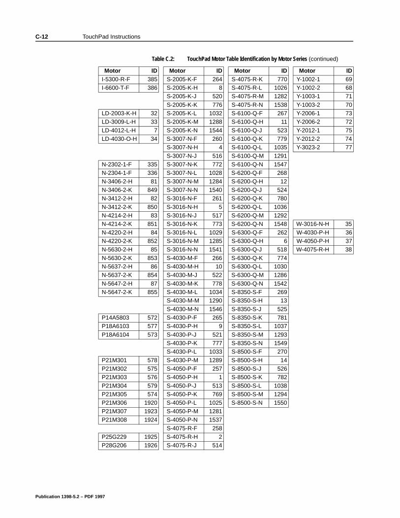
C-12 TouchPad Instructions
I-5300-R-F 385 S-2005-K-F 264 S-4075-R-K 770 Y-1002-1 69I-6600-T-F 386 S-2005-K-H 8 S-4075-R-L 1026 Y-1002-2 68
S-2005-K-J 520 S-4075-R-M 1282 Y-1003-1 71
S-2005-K-K 776 S-4075-R-N 1538 Y-1003-2 70LD-2003-K-H 32 S-2005-K-L 1032 S-6100-Q-F 267 Y-2006-1 73LD-3009-L-H 33 S-2005-K-M 1288 S-6100-Q-H 11 Y-2006-2 72
LD-4012-L-H 7 S-2005-K-N 1544 S-6100-Q-J 523 Y-2012-1 75LD-4030-O-H 34 S-3007-N-F 260 S-6100-Q-K 779 Y-2012-2 74
S-3007-N-H 4 S-6100-Q-L 1035 Y-3023-2 77
S-3007-N-J 516 S-6100-Q-M 1291N-2302-1-F 335 S-3007-N-K 772 S-6100-Q-N 1547N-2304-1-F 336 S-3007-N-L 1028 S-6200-Q-F 268
N-3406-2-H 81 S-3007-N-M 1284 S-6200-Q-H 12N-3406-2-K 849 S-3007-N-N 1540 S-6200-Q-J 524N-3412-2-H 82 S-3016-N-F 261 S-6200-Q-K 780
N-3412-2-K 850 S-3016-N-H 5 S-6200-Q-L 1036N-4214-2-H 83 S-3016-N-J 517 S-6200-Q-M 1292N-4214-2-K 851 S-3016-N-K 773 S-6200-Q-N 1548 W-3016-N-H 35
N-4220-2-H 84 S-3016-N-L 1029 S-6300-Q-F 262 W-4030-P-H 36N-4220-2-K 852 S-3016-N-M 1285 S-6300-Q-H 6 W-4050-P-H 37N-5630-2-H 85 S-3016-N-N 1541 S-6300-Q-J 518 W-4075-R-H 38
N-5630-2-K 853 S-4030-M-F 266 S-6300-Q-K 774N-5637-2-H 86 S-4030-M-H 10 S-6300-Q-L 1030N-5637-2-K 854 S-4030-M-J 522 S-6300-Q-M 1286
N-5647-2-H 87 S-4030-M-K 778 S-6300-Q-N 1542N-5647-2-K 855 S-4030-M-L 1034 S-8350-S-F 269
S-4030-M-M 1290 S-8350-S-H 13
S-4030-M-N 1546 S-8350-S-J 525P14A5803 572 S-4030-P-F 265 S-8350-S-K 781P18A6103 577 S-4030-P-H 9 S-8350-S-L 1037
P18A6104 573 S-4030-P-J 521 S-8350-S-M 1293S-4030-P-K 777 S-8350-S-N 1549S-4030-P-L 1033 S-8500-S-F 270
P21M301 578 S-4030-P-M 1289 S-8500-S-H 14P21M302 575 S-4050-P-F 257 S-8500-S-J 526P21M303 576 S-4050-P-H 1 S-8500-S-K 782
P21M304 579 S-4050-P-J 513 S-8500-S-L 1038P21M305 574 S-4050-P-K 769 S-8500-S-M 1294P21M306 1920 S-4050-P-L 1025 S-8500-S-N 1550
P21M307 1923 S-4050-P-M 1281P21M308 1924 S-4050-P-N 1537
S-4075-R-F 258
P25G229 1925 S-4075-R-H 2P28G206 1926 S-4075-R-J 514
Table C.2: TouchPad Motor Table Identification by Motor Series (continued)
Motor ID Motor ID Motor ID Motor ID
Publication 1398-5.2 – PDF 1997
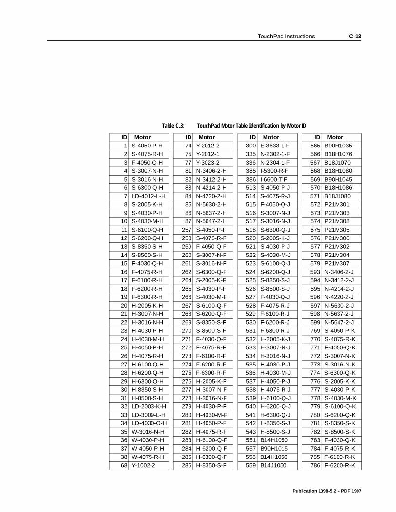
TouchPad Instructions C-13
Table C.3: TouchPad Motor Table Identification by Motor ID
ID Motor ID Motor ID Motor ID Motor1 S-4050-P-H 74 Y-2012-2 300 E-3633-L-F 565 B90H1035
2 S-4075-R-H 75 Y-2012-1 335 N-2302-1-F 566 B18H10763 F-4050-Q-H 77 Y-3023-2 336 N-2304-1-F 567 B18J10704 S-3007-N-H 81 N-3406-2-H 385 I-5300-R-F 568 B18H1080
5 S-3016-N-H 82 N-3412-2-H 386 I-6600-T-F 569 B90H10456 S-6300-Q-H 83 N-4214-2-H 513 S-4050-P-J 570 B18H10867 LD-4012-L-H 84 N-4220-2-H 514 S-4075-R-J 571 B18J1080
8 S-2005-K-H 85 N-5630-2-H 515 F-4050-Q-J 572 P21M3019 S-4030-P-H 86 N-5637-2-H 516 S-3007-N-J 573 P21M303
10 S-4030-M-H 87 N-5647-2-H 517 S-3016-N-J 574 P21M308
11 S-6100-Q-H 257 S-4050-P-F 518 S-6300-Q-J 575 P21M30512 S-6200-Q-H 258 S-4075-R-F 520 S-2005-K-J 576 P21M30613 S-8350-S-H 259 F-4050-Q-F 521 S-4030-P-J 577 P21M302
14 S-8500-S-H 260 S-3007-N-F 522 S-4030-M-J 578 P21M30415 F-4030-Q-H 261 S-3016-N-F 523 S-6100-Q-J 579 P21M30716 F-4075-R-H 262 S-6300-Q-F 524 S-6200-Q-J 593 N-3406-2-J
17 F-6100-R-H 264 S-2005-K-F 525 S-8350-S-J 594 N-3412-2-J18 F-6200-R-H 265 S-4030-P-F 526 S-8500-S-J 595 N-4214-2-J19 F-6300-R-H 266 S-4030-M-F 527 F-4030-Q-J 596 N-4220-2-J
20 H-2005-K-H 267 S-6100-Q-F 528 F-4075-R-J 597 N-5630-2-J21 H-3007-N-H 268 S-6200-Q-F 529 F-6100-R-J 598 N-5637-2-J22 H-3016-N-H 269 S-8350-S-F 530 F-6200-R-J 599 N-5647-2-J
23 H-4030-P-H 270 S-8500-S-F 531 F-6300-R-J 769 S-4050-P-K24 H-4030-M-H 271 F-4030-Q-F 532 H-2005-K-J 770 S-4075-R-K25 H-4050-P-H 272 F-4075-R-F 533 H-3007-N-J 771 F-4050-Q-K
26 H-4075-R-H 273 F-6100-R-F 534 H-3016-N-J 772 S-3007-N-K27 H-6100-Q-H 274 F-6200-R-F 535 H-4030-P-J 773 S-3016-N-K28 H-6200-Q-H 275 F-6300-R-F 536 H-4030-M-J 774 S-6300-Q-K
29 H-6300-Q-H 276 H-2005-K-F 537 H-4050-P-J 776 S-2005-K-K30 H-8350-S-H 277 H-3007-N-F 538 H-4075-R-J 777 S-4030-P-K31 H-8500-S-H 278 H-3016-N-F 539 H-6100-Q-J 778 S-4030-M-K
32 LD-2003-K-H 279 H-4030-P-F 540 H-6200-Q-J 779 S-6100-Q-K33 LD-3009-L-H 280 H-4030-M-F 541 H-6300-Q-J 780 S-6200-Q-K34 LD-4030-O-H 281 H-4050-P-F 542 H-8350-S-J 781 S-8350-S-K
35 W-3016-N-H 282 H-4075-R-F 543 H-8500-S-J 782 S-8500-S-K36 W-4030-P-H 283 H-6100-Q-F 551 B14H1050 783 F-4030-Q-K37 W-4050-P-H 284 H-6200-Q-F 557 B90H1015 784 F-4075-R-K
38 W-4075-R-H 285 H-6300-Q-F 558 B14H1056 785 F-6100-R-K68 Y-1002-2 286 H-8350-S-F 559 B14J1050 786 F-6200-R-K
Publication 1398-5.2 – PDF 1997
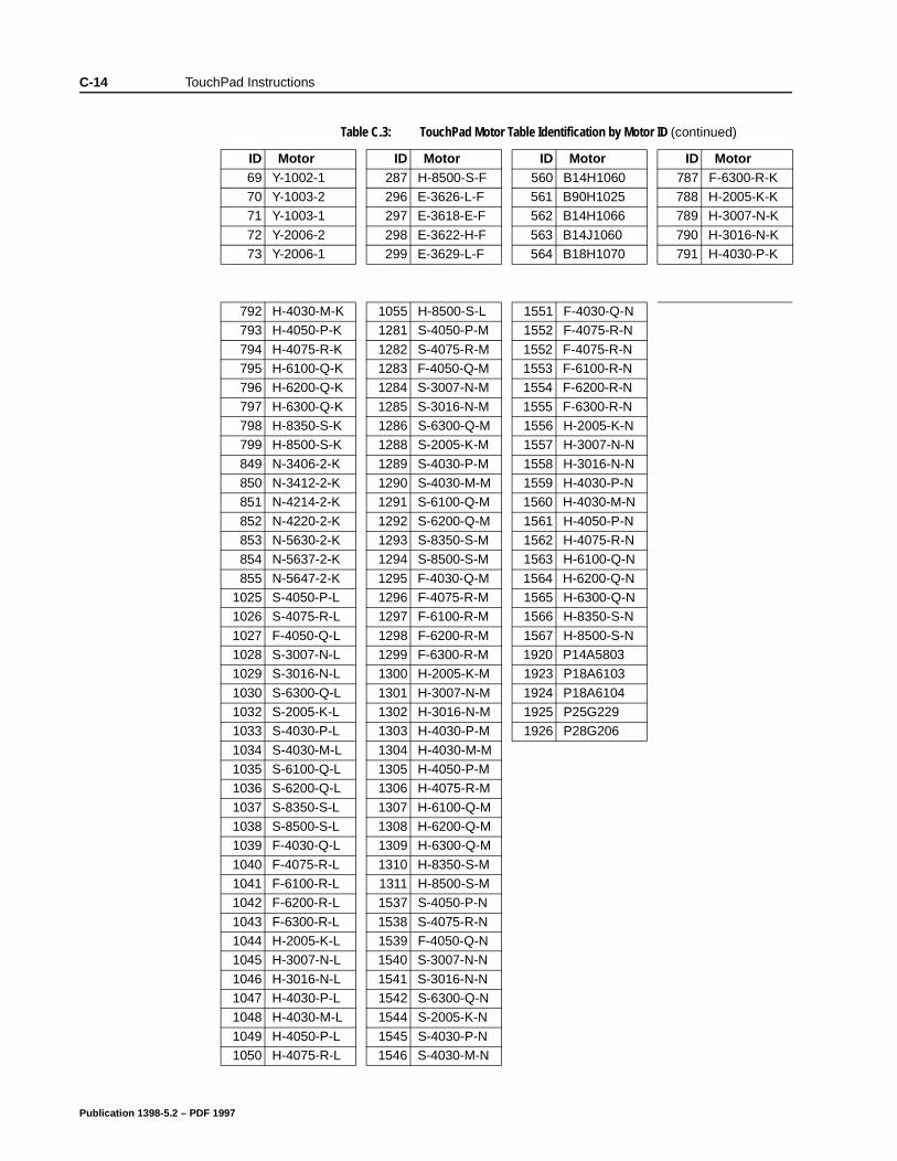
C-14 TouchPad Instructions
69 Y-1002-1 287 H-8500-S-F 560 B14H1060 787 F-6300-R-K70 Y-1003-2 296 E-3626-L-F 561 B90H1025 788 H-2005-K-K71 Y-1003-1 297 E-3618-E-F 562 B14H1066 789 H-3007-N-K
72 Y-2006-2 298 E-3622-H-F 563 B14J1060 790 H-3016-N-K73 Y-2006-1 299 E-3629-L-F 564 B18H1070 791 H-4030-P-K
792 H-4030-M-K 1055 H-8500-S-L 1551 F-4030-Q-N793 H-4050-P-K 1281 S-4050-P-M 1552 F-4075-R-N
794 H-4075-R-K 1282 S-4075-R-M 1552 F-4075-R-N795 H-6100-Q-K 1283 F-4050-Q-M 1553 F-6100-R-N796 H-6200-Q-K 1284 S-3007-N-M 1554 F-6200-R-N
797 H-6300-Q-K 1285 S-3016-N-M 1555 F-6300-R-N798 H-8350-S-K 1286 S-6300-Q-M 1556 H-2005-K-N799 H-8500-S-K 1288 S-2005-K-M 1557 H-3007-N-N
849 N-3406-2-K 1289 S-4030-P-M 1558 H-3016-N-N850 N-3412-2-K 1290 S-4030-M-M 1559 H-4030-P-N851 N-4214-2-K 1291 S-6100-Q-M 1560 H-4030-M-N
852 N-4220-2-K 1292 S-6200-Q-M 1561 H-4050-P-N853 N-5630-2-K 1293 S-8350-S-M 1562 H-4075-R-N854 N-5637-2-K 1294 S-8500-S-M 1563 H-6100-Q-N
855 N-5647-2-K 1295 F-4030-Q-M 1564 H-6200-Q-N1025 S-4050-P-L 1296 F-4075-R-M 1565 H-6300-Q-N1026 S-4075-R-L 1297 F-6100-R-M 1566 H-8350-S-N
1027 F-4050-Q-L 1298 F-6200-R-M 1567 H-8500-S-N1028 S-3007-N-L 1299 F-6300-R-M 1920 P14A58031029 S-3016-N-L 1300 H-2005-K-M 1923 P18A6103
1030 S-6300-Q-L 1301 H-3007-N-M 1924 P18A61041032 S-2005-K-L 1302 H-3016-N-M 1925 P25G2291033 S-4030-P-L 1303 H-4030-P-M 1926 P28G206
1034 S-4030-M-L 1304 H-4030-M-M1035 S-6100-Q-L 1305 H-4050-P-M1036 S-6200-Q-L 1306 H-4075-R-M
1037 S-8350-S-L 1307 H-6100-Q-M1038 S-8500-S-L 1308 H-6200-Q-M1039 F-4030-Q-L 1309 H-6300-Q-M
1040 F-4075-R-L 1310 H-8350-S-M1041 F-6100-R-L 1311 H-8500-S-M1042 F-6200-R-L 1537 S-4050-P-N
1043 F-6300-R-L 1538 S-4075-R-N1044 H-2005-K-L 1539 F-4050-Q-N1045 H-3007-N-L 1540 S-3007-N-N
1046 H-3016-N-L 1541 S-3016-N-N1047 H-4030-P-L 1542 S-6300-Q-N1048 H-4030-M-L 1544 S-2005-K-N
1049 H-4050-P-L 1545 S-4030-P-N1050 H-4075-R-L 1546 S-4030-M-N
Table C.3: TouchPad Motor Table Identification by Motor ID (continued)
ID Motor ID Motor ID Motor ID Motor
Publication 1398-5.2 – PDF 1997

TouchPad Instructions C-15
1051 H-6100-Q-L 1547 S-6100-Q-N1052 H-6200-Q-L 1548 S-6200-Q-N1053 H-6300-Q-L 1549 S-8350-S-N
1054 H-8350-S-L 1550 S-8500-S-N
Table C.3: TouchPad Motor Table Identification by Motor ID (continued)
ID Motor ID Motor ID Motor ID Motor
Publication 1398-5.2 – PDF 1997
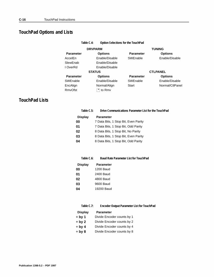
C-16 TouchPad Instructions
TouchPad Options and Lists
TouchPad Lists
Table C.4: Option Selections for the TouchPad
DRVPARM TUNINGParameter Options Parameter Options
AccelEn Enable/Disable SWEnable Enable/DisableSlewEnab Enable/DisableI OverRd Enable/Disable
STATUS CTLPANELParameter Options Parameter Options
SWEnable Enable/Disable SWEnable Enable/Disable
EncAlign Normal/Align Start Normal/CtlPanelRmvOfst to Rmv
Table C.5: Drive Communications Parameter List for the TouchPad
Display Parameter
00 7 Data Bits, 1 Stop Bit, Even Parity
01 7 Data Bits, 1 Stop Bit, Odd Parity
02 8 Data Bits, 1 Stop Bit, No Parity
03 8 Data Bits, 1 Stop Bit, Even Parity
04 8 Data Bits, 1 Stop Bit, Odd Parity
Table C.6: Baud Rate Parameter List for TouchPad
Display Parameter
00 1200 Baud
01 2400 Baud
02 4800 Baud
03 9600 Baud
04 19200 Baud
Table C.7: Encoder Output Parameter List for TouchPad
Display Parameter
÷ by 1 Divide Encoder counts by 1
÷ by 2 Divide Encoder counts by 2
÷ by 4 Divide Encoder counts by 4
÷ by 8 Divide Encoder counts by 8
Publication 1398-5.2 – PDF 1997
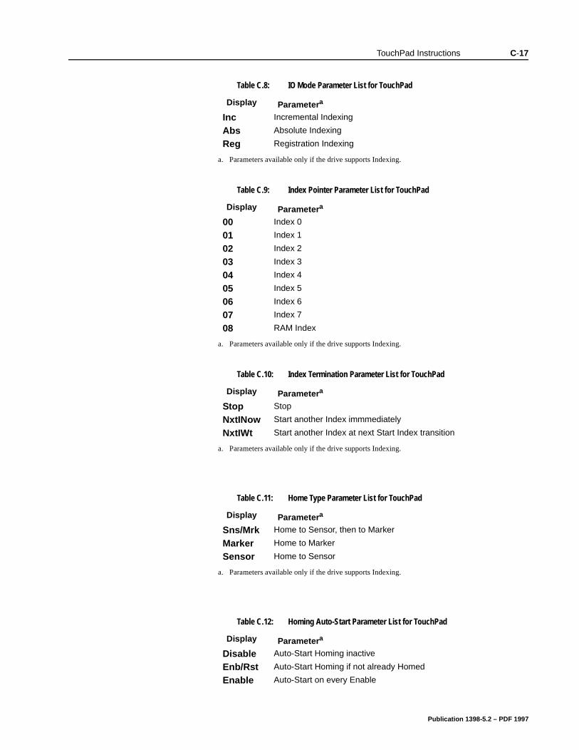
TouchPad Instructions C-17
Table C.8: IO Mode Parameter List for TouchPad
Display Parametera
Inc Incremental Indexing
Abs Absolute Indexing
Reg Registration Indexing
a. Parameters available only if the drive supports Indexing.
Table C.9: Index Pointer Parameter List for TouchPad
Display Parametera
00 Index 0
01 Index 1
02 Index 2
03 Index 3
04 Index 4
05 Index 5
06 Index 6
07 Index 7
08 RAM Index
a. Parameters available only if the drive supports Indexing.
Table C.10: Index Termination Parameter List for TouchPad
Display Parametera
Stop Stop
NxtINow Start another Index immmediately
NxtIWt Start another Index at next Start Index transition
a. Parameters available only if the drive supports Indexing.
Table C.11: Home Type Parameter List for TouchPad
Display Parametera
Sns/Mrk Home to Sensor, then to Marker
Marker Home to Marker
Sensor Home to Sensor
a. Parameters available only if the drive supports Indexing.
Table C.12: Homing Auto-Start Parameter List for TouchPad
Display Parametera
Disable Auto-Start Homing inactive
Enb/Rst Auto-Start Homing if not already Homed
Enable Auto-Start on every Enable
Publication 1398-5.2 – PDF 1997
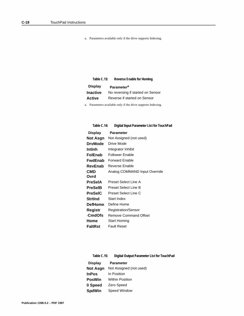
C-18 TouchPad Instructions
a. Parameters available only if the drive supports Indexing.
Table C.13: Reverse Enable for Homing
Display Parametera
Inactive No reversing if started on Sensor
Active Reverse if started on Sensor
a. Parameters available only if the drive supports Indexing.
Table C.14: Digital Input Parameter List for TouchPad
Display Parameter
Not Asgn Not Assigned (not used)
DrvMode Drive Mode
IntInh Integrator Inhibit
FolEnab Follower Enable
FwdEnab Forward Enable
RevEnab Reverse Enable
CMD Ovrd
Analog COMMAND Input Override
PreSelA Preset Select Line A
PreSelB Preset Select Line B
PreSelC Preset Select Line C
StrtInd Start Index
DefHome Define Home
Registr Registration/Sensor
-CmdOfs Remove Command Offset
Home Start Homing
FaltRst Fault Reset
Table C.15: Digital Output Parameter List for TouchPad
Display Parameter
Not Asgn Not Assigned (not used)
InPos In Position
PosWin Within Position
0 Speed Zero Speed
SpdWin Speed Window
Publication 1398-5.2 – PDF 1997
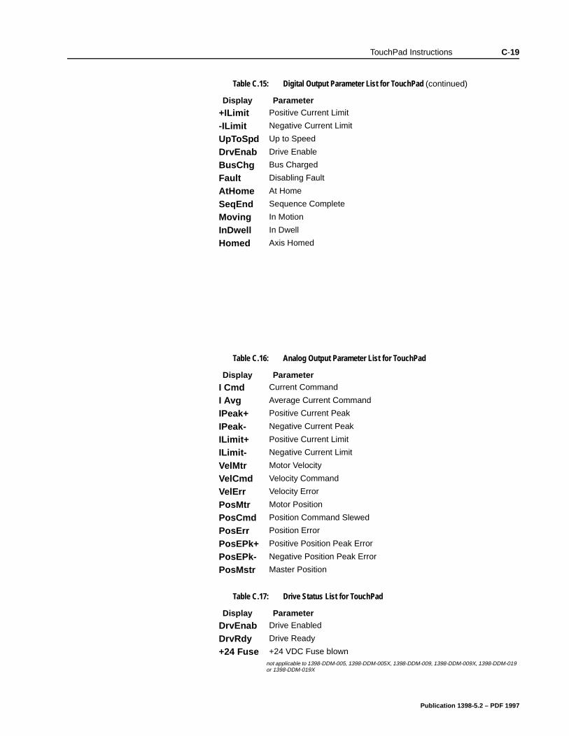
TouchPad Instructions C-19
+ILimit Positive Current Limit
-ILimit Negative Current Limit
UpToSpd Up to Speed
DrvEnab Drive Enable
BusChg Bus Charged
Fault Disabling Fault
AtHome At Home
SeqEnd Sequence Complete
Moving In Motion
InDwell In Dwell
Homed Axis Homed
Table C.15: Digital Output Parameter List for TouchPad (continued)
Display Parameter
Table C.16: Analog Output Parameter List for TouchPad
Display Parameter
I Cmd Current Command
I Avg Average Current Command
IPeak+ Positive Current Peak
IPeak- Negative Current Peak
ILimit+ Positive Current Limit
ILimit- Negative Current Limit
VelMtr Motor Velocity
VelCmd Velocity Command
VelErr Velocity Error
PosMtr Motor Position
PosCmd Position Command Slewed
PosErr Position Error
PosEPk+ Positive Position Peak Error
PosEPk- Negative Position Peak Error
PosMstr Master Position
Table C.17: Drive Status List for TouchPad
Display Parameter
DrvEnab Drive Enabled
DrvRdy Drive Ready
+24 Fuse +24 VDC Fuse blown not applicable to 1398-DDM-005, 1398-DDM-005X, 1398-DDM-009, 1398-DDM-009X, 1398-DDM-019 or 1398-DDM-019X
Publication 1398-5.2 – PDF 1997
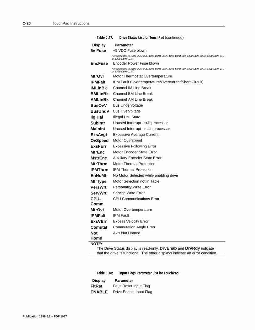
C-20 TouchPad Instructions
5v Fuse +5 VDC Fuse blown not applicable to 1398-DDM-005, 1398-DDM-005X, 1398-DDM-009, 1398-DDM-009X, 1398-DDM-019 or 1398-DDM-019X
EncFuse Encoder Power Fuse blownnot applicable to 1398-DDM-005, 1398-DDM-005X, 1398-DDM-009, 1398-DDM-009X, 1398-DDM-019 or 1398-DDM-019X
MtrOvT Motor Thermostat Overtemperature
IPMFalt IPM Fault (Overtemperature/Overcurrent/Short Circuit)
IMLinBk Channel IM Line Break
BMLinBk Channel BM Line Break
AMLinBk Channel AM Line Break
BusOvV Bus Undervoltage
BusUndV Bus Overvoltage
IlglHal Illegal Hall State
SubIntr Unused Interrupt - sub processor
MainInt Unused Interrupt - main processor
ExsAvgI Excessive Average Current
OvSpeed Motor Overspeed
ExsFErr Excessive Following Error
MtrEnc Motor Encoder State Error
MstrEnc Auxiliary Encoder State Error
MtrThrm Motor Thermal Protection
IPMThrm IPM Thermal Protection
EnNoMtr No Motor Selected while enabling drive
MtrType Motor Selection not in Table
PersWrt Personality Write Error
ServWrt Service Write Error
CPU-Comm
CPU Communications Error
MtrOvt Motor Overtemperature
IPMFalt IPM Fault
ExsVErr Excess Velocity Error
Comutat Commutation Angle Error
Not Homd
Axis Not Homed
NOTE: The Drive Status display is read-only. DrvEnab and DrvRdy indicate that the drive is functional. The other displays indicate an error condition.
Table C.17: Drive Status List for TouchPad (continued)
Display Parameter
Table C.18: Input Flags Parameter List for TouchPad
Display Parameter
FltRst Fault Reset Input Flag
ENABLE Drive Enable Input Flag
Publication 1398-5.2 – PDF 1997
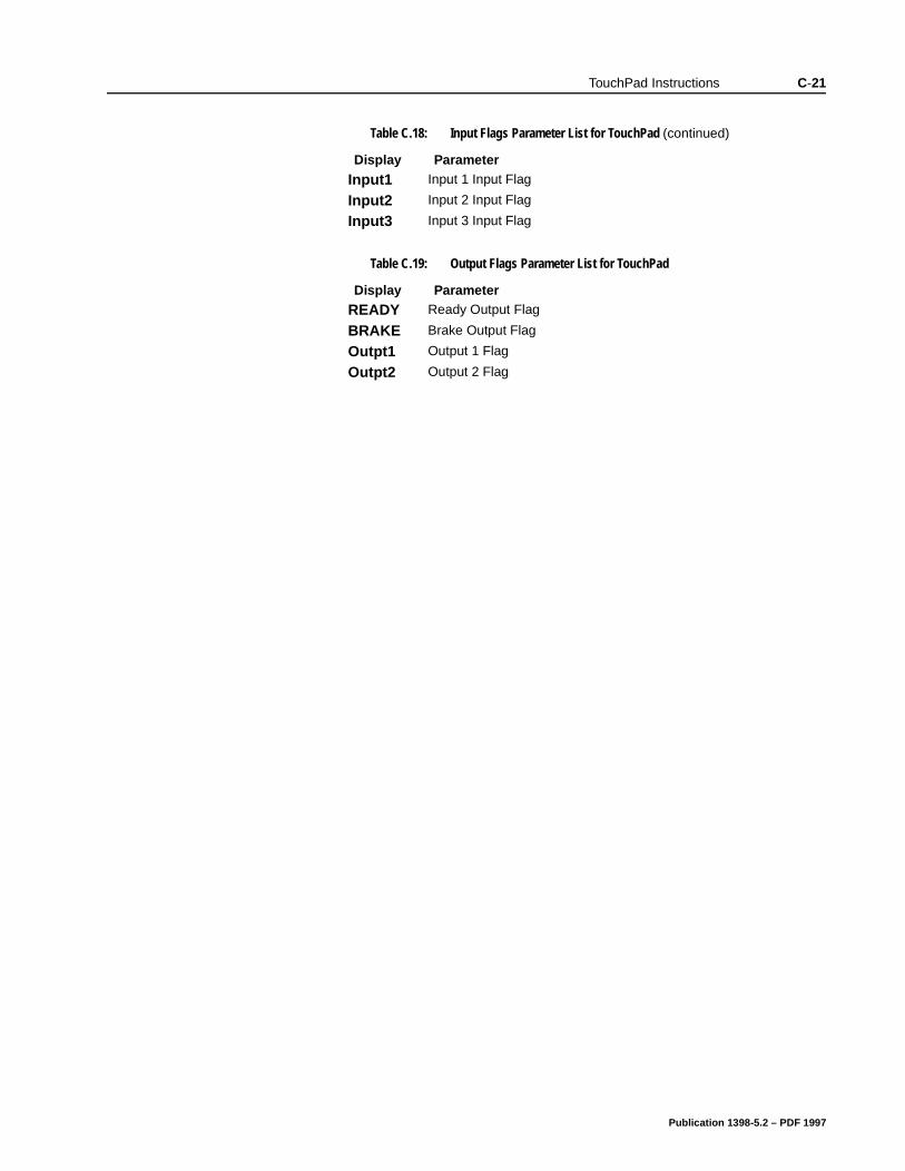
TouchPad Instructions C-21
Input1 Input 1 Input Flag
Input2 Input 2 Input Flag
Input3 Input 3 Input Flag
Table C.19: Output Flags Parameter List for TouchPad
Display Parameter
READY Ready Output Flag
BRAKE Brake Output Flag
Outpt1 Output 1 Flag
Outpt2 Output 2 Flag
Table C.18: Input Flags Parameter List for TouchPad (continued)
Display Parameter
Publication 1398-5.2 – PDF 1997

C-22 TouchPad Instructions
Publication 1398-5.2 – PDF 1997
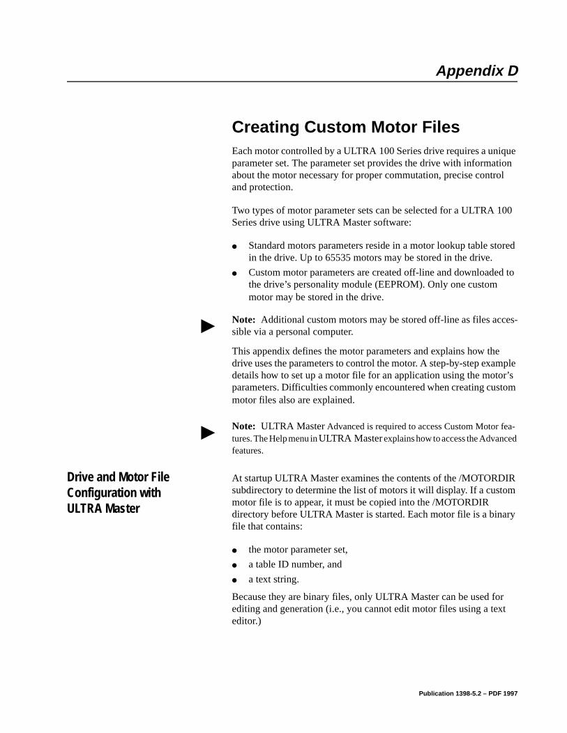
Appendix D
ple
r’s tom
IR m
ry
t
Creating Custom Motor Files Appendix D
Each motor controlled by a ULTRA 100 Series drive requires a unique parameter set. The parameter set provides the drive with information about the motor necessary for proper commutation, precise control and protection.
Two types of motor parameter sets can be selected for a ULTRA 100 Series drive using ULTRA Master software:
Standard motors parameters reside in a motor lookup table stored in the drive. Up to 65535 motors may be stored in the drive.
Custom motor parameters are created off-line and downloaded to the drive’s personality module (EEPROM). Only one custom motor may be stored in the drive.
This appendix defines the motor parameters and explains how thedrive uses the parameters to control the motor. A step-by-step examdetails how to set up a motor file for an application using the motoparameters. Difficulties commonly encountered when creating cusmotor files also are explained.
Drive and Motor File Configuration with ULTRA Master
At startup ULTRA Master examines the contents of the /MOTORDsubdirectory to determine the list of motors it will display. If a customotor file is to appear, it must be copied into the /MOTORDIR directory before ULTRA Master is started. Each motor file is a binafile that contains:
the motor parameter set,
a table ID number, and
a text string.
Because they are binary files, only ULTRA Master can be used forediting and generation (i.e., you cannot edit motor files using a texeditor.)
Note: Additional custom motors may be stored off-line as files acces-sible via a personal computer.
Note: ULTRA Master Advanced is required to access Custom Motor fea-tures. The Help menu in ULTRA Master explains how to access the Advanced features.
Publication 1398-5.2 – PDF 1997
D-2 Creating Custom Motor Files
ve
Motor Parameter Set
The motor parameter set configures the ULTRA 100 Series drive to control a specific motor. Motor parameters provide information about the electrical properties, ratings and construction of the motor. Subsequent sections of this appendix explain these properties with meaningful depth. For now it is sufficient to know that accurate and complete definition of the motor’s properties is necessary to achiegood performance.
Publication 1398-5.2 – PDF 1997
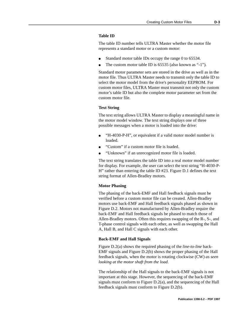
Creating Custom Motor Files D-3
n the to m e
in
ber 0-P-t
n in nd all
all
all
Table ID
The table ID number tells ULTRA Master whether the motor file represents a standard motor or a custom motor:
Standard motor table IDs occupy the range 0 to 65534.
The custom motor table ID is 65535 (also known as “-1”).
Standard motor parameter sets are stored in the drive as well as imotor file. Thus ULTRA Master needs to transmit only the table IDselect the motor model from the drive's personality EEPROM. Forcustom motor files, ULTRA Master must transmit not only the customotor’s table ID but also the complete motor parameter set from thcustom motor file.
Text String
The text string allows ULTRA Master to display a meaningful namethe motor model window. The text string displays one of three possible messages when a motor is loaded into the drive:
“H-4030-P-H”, or equivalent if a valid motor model number is loaded.
“Custom” if a custom motor file is loaded.
“Unknown” if an unrecognized motor file is loaded.
The text string translates the table ID into a real motor model numfor display. For example, the user can select the text string “H-403H” rather than entering the table ID #23. Figure D.1 defines the texstring format of Allen-Bradley motors.
Motor Phasing
The phasing of the back-EMF and Hall feedback signals must be verified before a custom motor file can be created. Allen-Bradley motors use back-EMF and Hall feedback signals phased as showFigure D.2. Motors not manufactured by Allen-Bradley require theback-EMF and Hall feedback signals be phased to match those ofAllen-Bradley motors. Often this requires swapping of the R-, S-, aT-phase control signals with each other, as well as swapping the HA, Hall B, and Hall C signals with each other.
Back-EMF and Hall Signals
Figure D.2(a) shows the required phasing of the line-to-line back-EMF signals and Figure D.2(b) shows the proper phasing of the Hfeedback signals, when the motor is rotating clockwise (CW) as seen looking at the motor shaft from the load.
The relationship of the Hall signals to the back-EMF signals is notimportant at this stage. However, the sequencing of the back-EMFsignals must conform to Figure D.2(a), and the sequencing of the Hfeedback signals must conform to Figure D.2(b).
Publication 1398-5.2 – PDF 1997
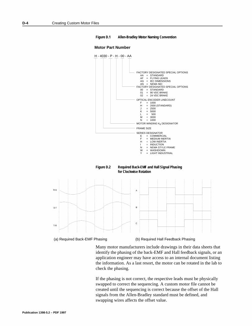
D-4 Creating Custom Motor Files
Many motor manufacturers include drawings in their data sheets that identify the phasing of the back-EMF and Hall feedback signals, or an application engineer may have access to an internal document listing the information. As a last resort, the motor can be rotated in the lab to check the phasing.
If the phasing is not correct, the respective leads must be physically swapped to correct the sequencing. A custom motor file cannot be created until the sequencing is correct because the offset of the Hall signals from the Allen-Bradley standard must be defined, and swapping wires affects the offset value.
Figure D.1 Allen-Bradley Motor Naming ConventionIntro
Figure D.2 Required Back-EMF and Hall Signal Phasing for Clockwise Rotation
Intro Intro
Intro(a) Required Back-EMF Phasing (b) Required Hall Feedback Phasing
Motor Part Number
H - 4030 - P - H - 00 - AA
MOTOR WINDING K DESIGNATORE
SERIES DESIGNATORE = COMMERCIALF = MEDIUM INERTIAH = LOW INERTIAI = INDUCTION
LD = LIGHT INDUSTRIALN = NEMA STYLE FRAMEW = WASHDOWNY = LIGHT INDUSTRIAL
FRAME SIZE
FACTORY DESIGNATED SPECIAL OPTIONS000102
===
STANDARD90 VDC BRAKE24 VDC BRAKE
OPTICAL ENCODER LINECOUNTFHJKLMN
=======
10002000 (STANDARD)25005000
50030001000
FACTORY DESIGNATED SPECIAL OPTIONSAAAFAGAN
====
STANDARDFLYING LEADSIEC DIMENSIONSNEMA 56C
FACTORY DESIGNATED SPECIAL OPTIONSAA = STANDARDAF = FLYING LEADSAG = IEC DIMENSIONSAN = NEMA 56C
FACTORY DESIGNATED SPECIAL OPTIONS00 = STANDARD01 = 90 VDC BRAKE02 = 24 VDC BRAKE
OPTICAL ENCODER LINECOUNTF = 1000H = 2000 (STANDARD)J = 2500K = 5000L = 500M = 3000N = 1000
MOTOR WINDING KE DESIGNATOR
FRAME SIZE
SERIES DESIGNATORE = COMMERCIALF = MEDIUM INERTIAH = LOW INERTIAI = INDUCTIONN = NEMA STYLE FRAMEW = WASHDOWNY = LIGHT INDUSTRIAL
Publication 1398-5.2 – PDF 1997
Creating Custom Motor Files D-5
Encoder Sequencing
Separate from the phasing of the commutation and motor power signals, the encoder A quad B signals must sequence properly. The A channel must lead the B channel for CW motion when viewed looking at the motor shaft from the load. Figure D.3 depicts this encoder signal sequencing. If the encoder phasing is not as shown in Figure D.3, the encoder leads must be swapped.
Motor Parameter Definitions
The parameters to configure in a custom motor file are defined below. ULTRA Master arranges motor parameters in an index card format. The groupings are:
General,
Feedback,
Current Loop,
Electrical, and
Ratings.
General Parameters
Motor Model
The motor model field is a text display from which a motor is selected.
If the motor model text string is changed, ULTRA Master assumes that a new motor file is being created, and the user must supply a new filename. This prevents the text string being changed on an existing motor file. However, a filename may be recycled by:
1. Assign the new file a tentative filename.
2. Delete the old file.
3. Rename the new file, using the old filename.
Figure D.3 Phasing of the Encoder Signals for Clockwise RotationIntro
Publication 1398-5.2 – PDF 1997
D-6 Creating Custom Motor Files
nly
t
xt e.
nt
o e nly
a ber
the m/
p,
Table ID
The table ID value determines whether the motor file represents a standard motor or a custom motor. A table ID in the range of 0 to 65534 identifies a standard motor file, and a table ID of 65535 (also known as table ID “-1”) identifies a custom motor file. Users may define motor parameters for multiple custom motors on a PC, but oone custom motor files may be stored on the drive. (i.e., All custommotor files have the table ID value of “-1”.)
Motor File
The motor file is the filename of the custom motor file, it is differenfrom the motor model text field. The filename can have up to 8 characters and must have a .MTR extension. If the motor model testring is altered, ULTRA Master prompts the user for a new filenam
Synchronous/Induction
This field identifies whether the motor is a synchronous (permanemagnet) motor or an induction motor. The motor type informs ULTRA Master which fields are valid for a particular motor, and which fields are invalid (grayed).
These instructions only cover permanent magnet motors, so the Synchronous box must be checked.
Number of Poles
The number of poles specifies the number of electrical cycles in twmechanical revolutions. For example, a 6-pole motor will have threelectrical cycles per mechanical cycle. The firmware can support o2-, 4-, 6-, and 8-pole motors.
Occasionally a manufacturer specifies the number of pole pairs inmotor data sheet. Pole pairs should not be confused with the numof poles. A 6-pole motor has 3 pole pairs.
KT (Torque Constant)
The torque constant, also known as the torque sensitivity, specifiesamount of torque that the motor can produce with a given value ofsinusoidal current. The torque constant is measured in units of N-Amp, and its range is 0.0002 to 15.9998 N-m/Amp.
Conversion formulas between N-m/Amp, in-lb/Amp, and oz-in/Amare:
Intro
1Newton meter
Amp8.85075
inch poundAmp
141.612ounce inch
Amp⋅ = ⋅ = ⋅
Publication 1398-5.2 – PDF 1997
Creating Custom Motor Files D-7
d as es a
que
tant,
39
lue.
The denominator units of the required torque constant are peak Amps, rather than rms Amps. To convert the torque constant from units of N-m/Amp(rms), use the formula:
Many Allen-Bradley motors specify the torque constant in units of N-m/rmsA/phase. In this case, in addition to conversion from rms Amps to peak Amps, the value needs to be multiplied by three because it has been defined as “per phase”.
If a motor operates with trap drives, the torque constant is specifiea “square wave” torque constant. However, ULTRA 100 Series drivare sinusoidal drives and the torque constant must be specified as“sine wave” torque constant or “sinusoidal” torque constant. To convert between sinusoidal torque constants and square wave torconstants, usually a factor of 5-10% is required. The motor manufacturer should be able to specify the sinusoidal torque conseven if it is not shown in the data sheet.
JM (Inertia)
The rotor inertia specifies the inertia of the motor, not including the
load, and is required in units of Kg-cm2. The inertia can be in the
range of 0.0156 to 1023.9844 Kg-cm2.
The conversion formulas between Kg-cm2, Kg-m2, in-lb-s2, and
oz-in-s2 are:
KE (Back EMF)
The back-EMF is the peak value of the line-to-line sinusoidal EMFgenerated at 1000 RPM, and is required in units of Volts/KRPM orVolts/1000 RPM. The back-EMF value can be in the range of 0.00to 255.9961 Volts/KRPM.
Note that the required value is a peak value, rather than an rms vaTo convert the back-EMF from units of Volts(rms)/kRPM, use the formula:
Intro
1Newton meter
Amp0.707
Newton meter
Amp(rms)
⋅=
⋅
Intro
1 Kg cm 0.0001 Kg m1
1129.85in lb s
170.6155
oz in s2 2 2 2⋅ ⋅ = ⋅ ⋅ = ⋅ ⋅ ⋅ = ⋅ ⋅ ⋅
Intro
1Volts
1000 RPMVolts(rms)1000 RPM
⋅ = ⋅1 414.
Publication 1398-5.2 – PDF 1997

D-8 Creating Custom Motor Files
Also, a line-to-line value is required, rather than a line-to-neutral. A line-to-line value equals a line-to-neutral value times two.
Publication 1398-5.2 – PDF 1997
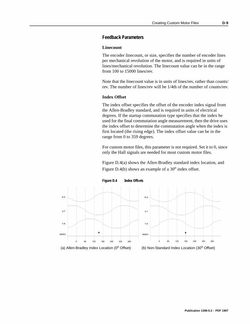
Creating Custom Motor Files D-9
Feedback Parameters
Linecount
The encoder linecount, or size, specifies the number of encoder lines per mechanical revolution of the motor, and is required in units of lines/mechanical revolution. The linecount value can be in the range from 100 to 15000 lines/rev.
Note that the linecount value is in units of lines/rev, rather than counts/rev. The number of lines/rev will be 1/4th of the number of counts/rev.
Index Offset
The index offset specifies the offset of the encoder index signal from the Allen-Bradley standard, and is required in units of electrical degrees. If the startup commutation type specifies that the index be used for the final commutation angle measurement, then the drive uses the index offset to determine the commutation angle when the index is first located (the rising edge). The index offset value can be in the range from 0 to 359 degrees.
For custom motor files, this parameter is not required. Set it to 0, since only the Hall signals are needed for most custom motor files.
Figure D.4(a) shows the Allen-Bradley standard index location, and
Figure D.4(b) shows an example of a 30o index offset.
Figure D.4 Index OffsetsIntro Intro
Intro(a) Allen-Bradley Index Location (0o Offset) (b) Non-Standard Index Location (30o Offset)
Publication 1398-5.2 – PDF 1997
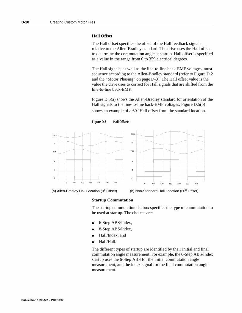
D-10 Creating Custom Motor Files
the
he
to
dex
e
Hall Offset
The Hall offset specifies the offset of the Hall feedback signals relative to the Allen-Bradley standard. The drive uses the Hall offset to determine the commutation angle at startup. Hall offset is specified as a value in the range from 0 to 359 electrical degrees.
The Hall signals, as well as the line-to-line back-EMF voltages, must sequence according to the Allen-Bradley standard (refer to Figure D.2 and the “Motor Phasing” on page D-3). The Hall offset value is thevalue the drive uses to correct for Hall signals that are shifted fromline-to-line back-EMF.
Figure D.5(a) shows the Allen-Bradley standard for orientation of tHall signals to the line-to-line back-EMF voltages. Figure D.5(b)
shows an example of a 60o Hall offset from the standard location.
Startup Commutation
The startup commutation list box specifies the type of commutationbe used at startup. The choices are:
6-Step ABS/Index,
8-Step ABS/Index,
Hall/Index, and
Hall/Hall.
The different types of startup are identified by their initial and final commutation angle measurement. For example, the 6-Step ABS/Instartup uses the 6-Step ABS for the initial commutation angle measurement, and the index signal for the final commutation anglmeasurement.
Figure D.5 Hall OffsetsIntro Intro
Intro(a) Allen-Bradley Hall Location (0o Offset) (b) Non-Standard Hall Location (60o Offset)
Publication 1398-5.2 – PDF 1997
Creating Custom Motor Files D-11
The Hall/Hall type of startup commutation should be used unless the motor is a special version of an Allen-Bradley motor. The reasons for this are:
The ABS signal is only available on Allen-Bradley motors.
Hall/Hall commutation means that the location of the Index signal is unimportant.
If the drive is set up for Hall/Hall startup commutation, the initial commutation angle is determined by the state of the three Hall feedback inputs: 001, 010, 011, 100, 101, or 110. When the motor begins moving, a transition from one Hall state to another (for example, 001 to 101) identifies a precise commutation angle, and the measurement is completed. After the final Hall measurement occurs, the encoder A/B inputs are used to track the commutation angle.
Invert Direction
The invert direction check box may be used as a substitute for swapping the motor phase leads and Hall feedback signal wires. This option is valid only if the motor runs backwards from the Allen-Bradley standard and only if counter-clockwise (CCW) rotation produces the same motor power and Hall feedback sequencing as rotating an Allen-Bradley motor clockwise (CW).
The invert direction check box may also be checked for some Allen-Bradley motors, where the definition of forward is opposite that of Allen-Bradley (i.e., CCW rather than CW). In such a case, a software inversion is preferable to the physical swapping of leads, because the signals look identical when rotated CCW rather than CW.
For custom motors, other than those mentioned above, leave this box unchecked and swap the motor power and Hall feedback signals to correct the phasing.
Electrical Parameters
Resistance
The resistance value is the measured phase-to-phase resistance of the stator winding in Ohms. The resistance is used to set the current regulator gains, and is critical to current loop performance. The resistance value can be in the range from 0.0039 to 255.9961Ω.
The ratio of motor inductance to motor resistance is defined as the electrical time constant of the motor. This value should always be checked to verify that it is in an acceptable range. Electrical time constants less than ~1mS, and higher than ~50mS, present difficulties for current regulation and should be avoided.
Publication 1398-5.2 – PDF 1997
D-12 Creating Custom Motor Files
Some manufacturers specify the resistance in Ohms/phase. The phase-to-phase resistance requested by ULTRA Master is twice the per phase value.
Inductance
The inductance value is the measured phase-to-phase inductance in milliHenries of the stator winding. The inductance is used to set the current regulator gains, and is critical to current loop performance. The inductance value can be in the range from 0.0039 to 255.9961mH.
The ratio of motor inductance to motor resistance is defined as the electrical time constant of the motor. Always verify this value is in a reasonable range. Electrical time constants less than ~1mS, and higher than about ~50mS, present difficulties in the current regulator and should be avoided.
Inductances less than ~1mH suffer from high current ripple, and are not recommended for use with the ULTRA 100 Series drives.
Some manufacturers specify the inductance in milliHenries/phase. The phase-to-phase inductance is twice the per phase value.
Publication 1398-5.2 – PDF 1997
Creating Custom Motor Files D-13
Rating Parameters
Continuous Torque
Continuous torque specifies the rated current of the motor in peak Amps. (Note: Continuous torque is peak Amps, rather than rms.) The drive uses the continuous torque current value in its motor thermal protection software. The drive generates a fault if the square of the actual current, after passing through a low pass filter, exceeds the square of the continuous torque current value. The square is used
because the power dissipation in the motor is approximated as I2R losses. The continuous torque value may be in the range from 0.0078 to 255.9922 Amps.
Some manufacturers specify the rated current of a motor in rms Amps. To convert from rms Amps to peak Amps, use the formula:
Occasionally a manufacturer specifies only the rated torque, and does not include the rated current specification. In such a case, the rated current can be computed using the rated torque and the torque constant. A factor of 1.1 is included to allow for degradation of the torque constant at high temperatures, etc. The formula, assuming the torque constant has already been converted to N-m/A(peak), is:
Peak Torque
The peak or maximum torque specifies the maximum current capability of the motor in peak Amps. (Note: This is peak Amps, rather than rms.) The drive uses the maximum torque value to limit the current applied to the motor. At run-time, the instantaneous current of the drive is limited to the minimum of this value, the drive’s peak rating, the analog current limit inputs, and the software current limits. The maximum torque value can be in the range from 0.0078 to 255.9922 Amps.
Some manufacturers specify the maximum current of a motor in rms Amps. To convert from rms Amps to peak Amps, use the formula:
Intro
1 Amps Amps(rms)⋅ = ⋅1414.
Intro
I 1.1rated torque in N m
KRATEDT
= ⋅⋅
Intro
1 Amps Amps(rms)⋅ = ⋅1414.
Publication 1398-5.2 – PDF 1997
D-14 Creating Custom Motor Files
Occasionally a manufacturer specifies only the maximum instantaneous torque, and does not include the maximum current specification. In such a case, the peak current can be computed using the peak torque and the torque constant. A factor of 1.1 is included to allow for degradation of the torque constant at high temperatures, etc. The formula, assuming the torque constant has already been converted to N-m/A(peak), is given by:
Thermal Time Constant
The thermal time constant check box indicates if a valid thermal time constant exists for the motor. If this check box is not selected, the motor thermal protection software is disabled.
Enabling of the motor thermal protection software is recommended, even if the thermal time constant is not known. This software feature significantly reduces the chance of damage to the motor, even when the motor has an integral thermostat.
The thermal time constant value, also known as the cool down time constant, identifies how fast the motor winding temperature dissipates heat. The value is entered in seconds. The thermal time constant value can be in the range from 1 to 65535 seconds.
The thermal time constant of the motor is measured by stabilizing the motor temperature at its rated condition, disabling the drive, and measuring the time for the hottest part of the motor winding to drop 63% of the difference from ambient. Allen-Bradley, as well as many other motor manufacturers, specifies this parameter for motors, although it may not be published in catalogs or data sheets.
If the thermal time constant of a motor is unknown or unavailable, an estimated value is preferable to disabling the motor thermal protection software. A reasonable substitute is to find an Allen-Bradley motor with similar capability, and use its thermal time constant value for the custom motor.
The motor thermal protection algorithm filters the square of the torque current (using the motor thermal time constant value) and generates a motor thermal protection fault if the output of the filter exceeds the square of the motor’s continuous torque current rating. The square of the current is used because the power dissipated in the motor is approximated as I2R losses. Figure D.6 shows the method to be used for protection, with t defined as the motor thermal time constant.
Intro
I 1.1maximum torque in N m
KPEAKT
= ⋅⋅
Publication 1398-5.2 – PDF 1997
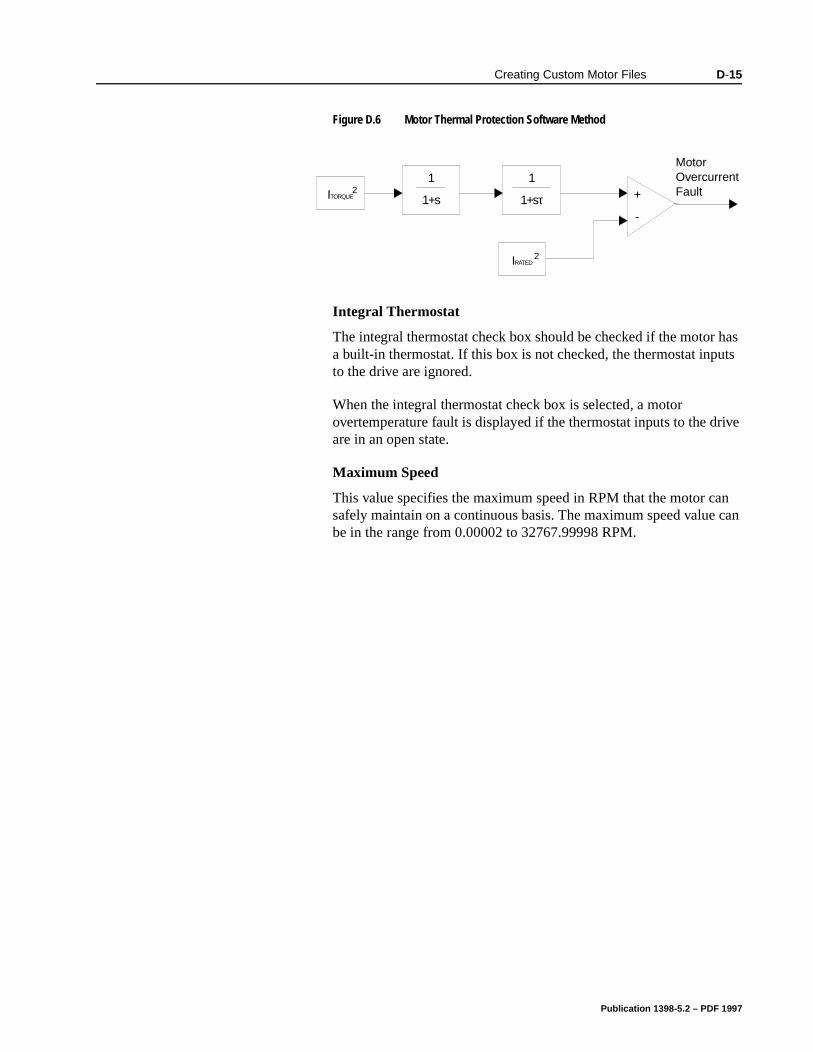
Creating Custom Motor Files D-15
Integral Thermostat
The integral thermostat check box should be checked if the motor has a built-in thermostat. If this box is not checked, the thermostat inputs to the drive are ignored.
When the integral thermostat check box is selected, a motor overtemperature fault is displayed if the thermostat inputs to the drive are in an open state.
Maximum Speed
This value specifies the maximum speed in RPM that the motor can safely maintain on a continuous basis. The maximum speed value can be in the range from 0.00002 to 32767.99998 RPM.
Figure D.6 Motor Thermal Protection Software MethodIntro
1
1+s
1
1+sτ +
-
ITORQUE2
IRATED2
Motor Overcurrent Fault
Publication 1398-5.2 – PDF 1997
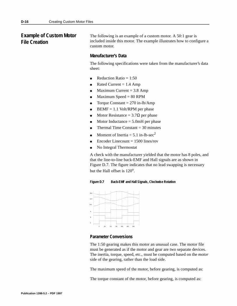
D-16 Creating Custom Motor Files
Example of Custom Motor File Creation
The following is an example of a custom motor. A 50:1 gear is included inside this motor. The example illustrates how to configure a custom motor.
Manufacturer’s Data
The following specifications were taken from the manufacturer’s data sheet:
Reduction Ratio = 1:50
Rated Current = 1.4 Amp
Maximum Current = 3.8 Amp
Maximum Speed = 80 RPM
Torque Constant = 270 in-lb/Amp
BEMF = 1.1 Volt/RPM per phase
Motor Resistance = 3.7Ω per phase
Motor Inductance = 5.0mH per phase
Thermal Time Constant = 30 minutes
Moment of Inertia = 5.1 in-lb-sec2
Encoder Linecount = 1500 lines/rev
No Integral Thermostat
A check with the manufacturer yielded that the motor has 8 poles, and that the line-to-line back-EMF and Hall signals are as shown in Figure D.7. The figure indicates that no lead swapping is necessary
but the Hall offset is 120o.
Parameter Conversions
The 1:50 gearing makes this motor an unusual case. The motor file must be generated as if the motor and gear are two separate devices. The inertia, torque, speed, etc., must be computed based on the motor side of the gearing, rather than the load side.
The maximum speed of the motor, before gearing, is computed as:
The torque constant of the motor, before gearing, is computed as:
Figure D.7 Back-EMF and Hall Signals, Clockwise RotationIntro
Publication 1398-5.2 – PDF 1997

Creating Custom Motor Files D-17
The back-EMF constant of the motor, before gearing, is computed as:
Note that the back-EMF was specified as a per phase value, and is doubled to obtain a line-to-line value.
The motor inertia, before gearing, is computed as:
The resistance and inductances are also specified as per phase values, and are computed as:
The thermal constant is specified in minutes, and is computed as:
Custom Motor File
The custom motor file parameters are as follows:
Intro
Intro
( )Vrevmin
50 4000 revminMAX =
⋅ =80
K 270in lbAmp
18.85075
N min lb
150
0.61N mAmpT = ⋅
⋅ ⋅
⋅
⋅
= ⋅
Intro
( )K 1.1VoltsRPM
10001
RPMKRPM
21
5044
VoltsKRPME =
⋅
⋅ ⋅
=
Intro
( )J 5 in lb s 1129.85Kg cmin lb s
150
2.26 Kg cmM2
2
2 22= ⋅ ⋅ ⋅ ⋅
⋅ ⋅
⋅
= ⋅
Intro
( )L 5.0mH
Phase2 10.0 mHL-L =
⋅ =
( )R 3.7OhmsPhase
2 7.4 OhmsL-L =
⋅ =
Intro
( )thermal time constant 30 min 60secmin
1800 sec= ⋅
=
GENERAL CURRENT LOOPMotor Model: A_CUSTOM Current Feedforward: 0 degrees / kRPMTable ID: -1Motor File: CUSTOM21.MTR ELECTRICALMotor Type: Synchronous Resistance: 7.4 OhmsNumber of Poles: 8 Inductance: 10.0 mHKt: 0.61 N-m/Amp
Publication 1398-5.2 – PDF 1997
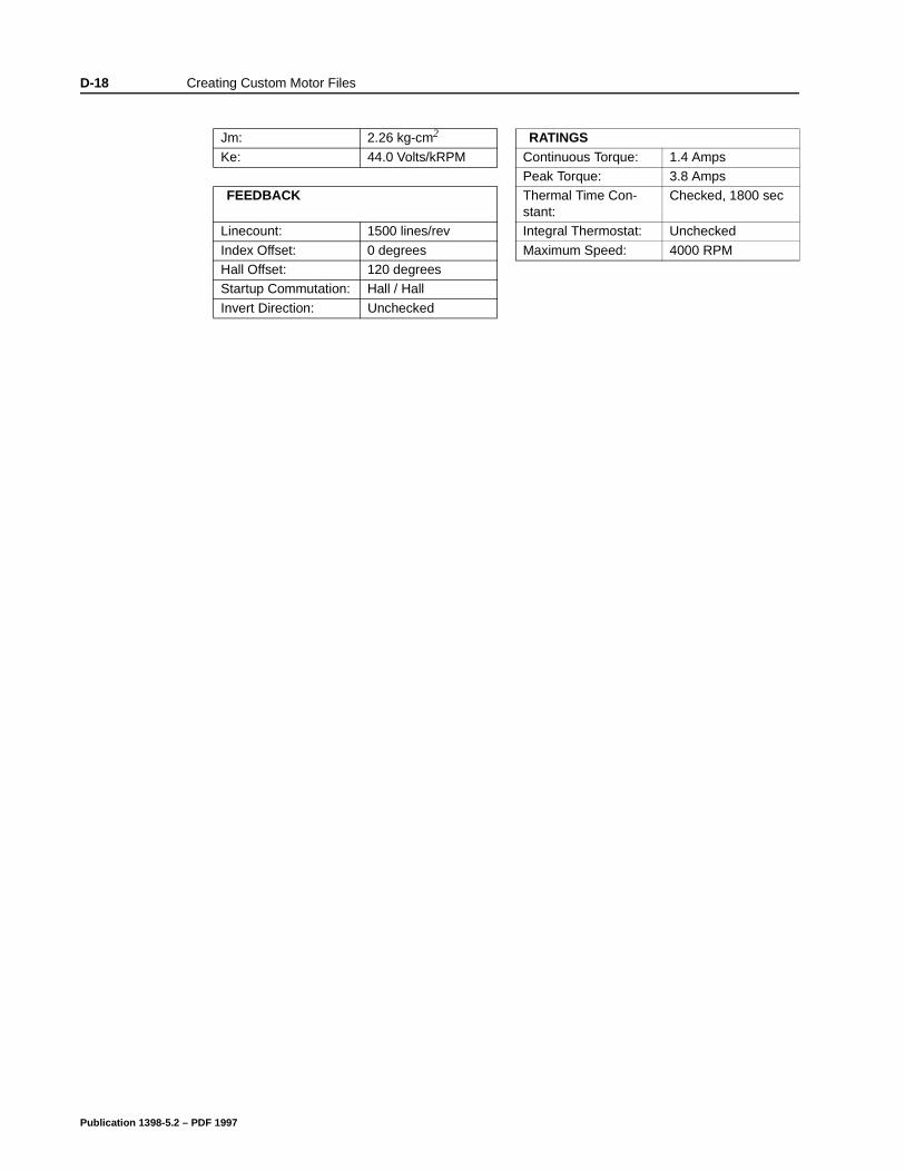
D-18 Creating Custom Motor Files
Jm: 2.26 kg-cm2 RATINGSKe: 44.0 Volts/kRPM Continuous Torque: 1.4 Amps
Peak Torque: 3.8 AmpsFEEDBACK Thermal Time Con-
stant:Checked, 1800 sec
Linecount: 1500 lines/rev Integral Thermostat: Unchecked
Index Offset: 0 degrees Maximum Speed: 4000 RPMHall Offset: 120 degreesStartup Commutation: Hall / Hall
Invert Direction: Unchecked
Publication 1398-5.2 – PDF 1997
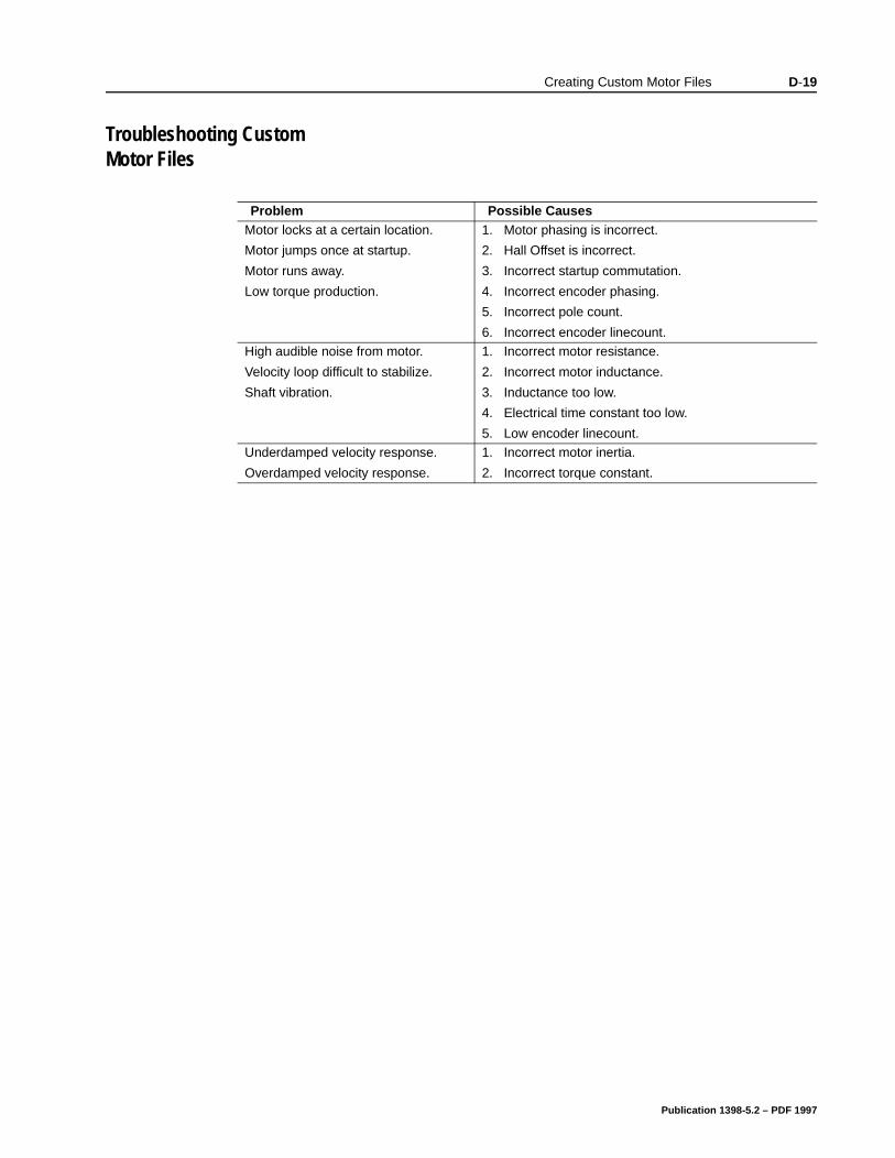
Creating Custom Motor Files D-19
Troubleshooting Custom Motor Files
Problem Possible CausesMotor locks at a certain location.
Motor jumps once at startup.
Motor runs away.
Low torque production.
1. Motor phasing is incorrect.
2. Hall Offset is incorrect.
3. Incorrect startup commutation.
4. Incorrect encoder phasing.
5. Incorrect pole count.
6. Incorrect encoder linecount.High audible noise from motor.
Velocity loop difficult to stabilize.
Shaft vibration.
1. Incorrect motor resistance.
2. Incorrect motor inductance.
3. Inductance too low.
4. Electrical time constant too low.
5. Low encoder linecount.Underdamped velocity response.
Overdamped velocity response.
1. Incorrect motor inertia.
2. Incorrect torque constant.
Publication 1398-5.2 – PDF 1997
Appendix E
3-ted
er,
od
n of
ne .
t a .
. an
an I
Electromagnetic Compatibility Guidelines for Machine Design Appendix E
This appendix provides background information about Electromagnetic Interference (EMI) and machine design guidelines for Electromagnetic Compatibility (EMC). Installation requirements for compliance to the European Electromagnetic Compatibility Directive are specified in “European Union Requirements” on page9. AC Line Filters necessary for European EMC compliance are lisin “AC Line Filters” on page 5-8.
Perhaps no other subject related to the installation of industrial electronic equipment is so misunderstood as electrical noise. Thesubject is complex and the theory easily fills a book. This section provides guidelines that can minimize noise problems.
The majority of installations do not exhibit noise problems. Howevthe filtering and shielding guidelines are provided as counter measures. The grounding guidelines provided below are simply gogrounding practices. They should be followed in all installations.
Electrical noise has two characteristics: the generation or emissioelectromagnetic interference (EMI), and response or immunity to EMI. The degree to which a device does not emit EMI, and is immuto EMI is called the device’s Electromagnetic Compatibility (EMC)
Equipment which is to be brought into the European Union legallyrequires a specific level of EMC. Since this applies when the equipment is brought into use, it is of considerable importance thadrive system, as a component of a machine, be correctly installed
“EMI Source-Victim Model” shows the commonly used EMI modelThe model consists of an EMI source, a coupling mechanism andEMI victim. Devices such as servo drives and computers, which contain switching power supplies and microprocessors, are EMI sources. The mechanisms for the coupling of energy between thesource and victim are conduction and radiation. Victim equipment cbe any electromagnetic device that is adversely affected by the EMcoupled to it.
Publication 1398-5.2 – PDF 1997
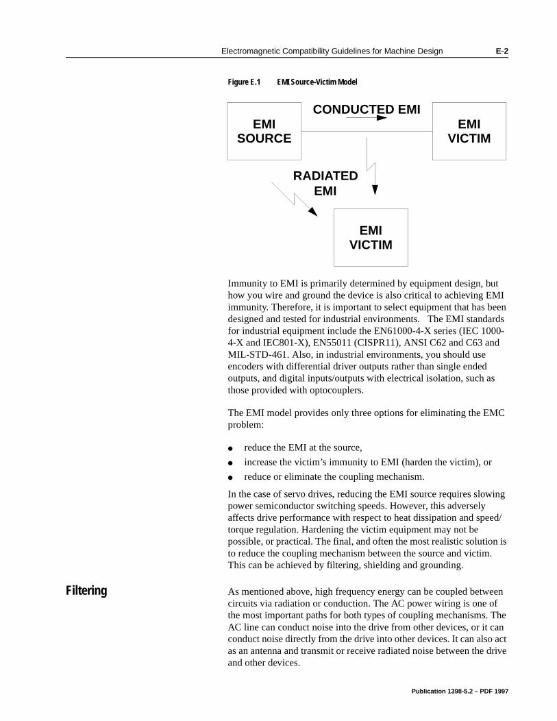
Electromagnetic Compatibility Guidelines for Machine Design E-2
ing
ed/
n is .
een The an act drive
Immunity to EMI is primarily determined by equipment design, but how you wire and ground the device is also critical to achieving EMI immunity. Therefore, it is important to select equipment that has been designed and tested for industrial environments. The EMI standards for industrial equipment include the EN61000-4-X series (IEC 1000-4-X and IEC801-X), EN55011 (CISPR11), ANSI C62 and C63 and MIL-STD-461. Also, in industrial environments, you should use encoders with differential driver outputs rather than single ended outputs, and digital inputs/outputs with electrical isolation, such as those provided with optocouplers.
The EMI model provides only three options for eliminating the EMC problem:
reduce the EMI at the source,
increase the victim’s immunity to EMI (harden the victim), or
reduce or eliminate the coupling mechanism.
In the case of servo drives, reducing the EMI source requires slowpower semiconductor switching speeds. However, this adversely affects drive performance with respect to heat dissipation and spetorque regulation. Hardening the victim equipment may not be possible, or practical. The final, and often the most realistic solutioto reduce the coupling mechanism between the source and victimThis can be achieved by filtering, shielding and grounding.
Filtering As mentioned above, high frequency energy can be coupled betwcircuits via radiation or conduction. The AC power wiring is one ofthe most important paths for both types of coupling mechanisms. AC line can conduct noise into the drive from other devices, or it cconduct noise directly from the drive into other devices. It can alsoas an antenna and transmit or receive radiated noise between theand other devices.
Figure E.1 EMI Source-Victim Model Intro
EMIVICTIM
EMISOURCE
EMIVICTIM
CONDUCTED EMI
RADIATEDEMI
Publication 1398-5.2 – PDF 1997
E-3 Electromagnetic Compatibility Guidelines for Machine Design
ed ef-
One method to improve the EMC characteristics of a drive is to use an isolation AC power transformer to feed the amplifier its input power. This minimizes inrush currents on power-up and provides electrical isolation. In addition, it provides common mode filtering, although the effect is limited in frequency by the interwinding capacitance. Use of a Faraday shield between the windings can increase the common mode rejection bandwidth, (shield terminated to ground) or provide differential mode shielding (shield terminated to the winding).
One alternative to AC line filters to reduce the conducted EMI emitting from the drive. This allows nearby equipment to operate undisturbed. In many cases an AC line filter will not be required unless other sensitive circuits are powered off the same AC branch circuit. The basic operating principle is to minimize the high frequency power transfer through the filter. An effective filter achieves this by using capacitors and inductors to mismatch the source impedance (AC line) and the load impedance (drive) at high frequencies.
For drives brought into use in Europe, use of the correct filter is essential to meet emission requirements. Detailed information on filters is included in the manual and transformers should be used where specified in the manual.
Note: “Common mode” noise is present on all conductors referencto ground. “Differential mode” noise is present on one conductor rerenced to another conductor.
Publication 1398-5.2 – PDF 1997
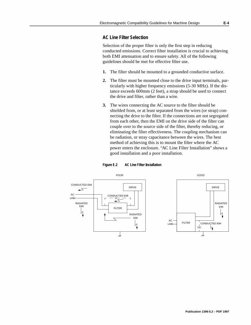
Electromagnetic Compatibility Guidelines for Machine Design E-4
a
AC Line Filter Selection
Selection of the proper filter is only the first step in reducing conducted emissions. Correct filter installation is crucial to achieving both EMI attenuation and to ensure safety. All of the following guidelines should be met for effective filter use.
1. The filter should be mounted to a grounded conductive surface.
2. The filter must be mounted close to the drive input terminals, par-ticularly with higher frequency emissions (5-30 MHz). If the dis-tance exceeds 600mm (2 feet), a strap should be used to connect the drive and filter, rather than a wire.
3. The wires connecting the AC source to the filter should be shielded from, or at least separated from the wires (or strap) con-necting the drive to the filter. If the connections are not segregated from each other, then the EMI on the drive side of the filter can couple over to the source side of the filter, thereby reducing, or eliminating the filter effectiveness. The coupling mechanism can be radiation, or stray capacitance between the wires. The best method of achieving this is to mount the filter where the AC power enters the enclosure. “AC Line Filter Installation” showsgood installation and a poor installation.
Figure E.2 AC Line Filter InstallationIntro
ACLINE
RADIATEDEMI
DRIVE
RADIATEDEMI
FILTER
CONDUCTED EMI
CONDUCTED EMI
POOR
ACLINE
DRIVE
RADIATEDEMI
FILTER CONDUCTED EMI
GOOD
Publication 1398-5.2 – PDF 1997
E-5 Electromagnetic Compatibility Guidelines for Machine Design
rent e t nd er
When multiple power cables enter an enclosure, an unfiltered line can contaminate a filtered line external to the enclosure. Therefore, all lines must be filtered to be effective. The situation is similar to a leaky boat. All the holes must be plugged to prevent sinking.
If the filter is mounted excessively far from the drive, it may be necessary to mount it to a grounded conductive surface, such as the enclosure, to establish a high frequency (HF) connection to that surface. To achieve the HF ground, direct contact between the mounting surface and the filter must be achieved. This may require removal of paint or other insulating material from the cabinet or panel.
The only reasonable filtering at the drive output terminals is the use of inductance. Capacitors would slow the output switching and deteriorate the drive performance. A common mode choke can be used to reduce the HF voltage at the drive output. This will reduce emission coupling through the drive back to the AC line. However, the motor cable still carries a large HF voltage and current. Therefore, it is very important to segregate the motor cable from the AC power cable. More information on cable shielding and segregation is contained in the section on shielding.
Grounding High frequency (HF) grounding is different from safety grounding. A long wire is sufficient for a safety ground, but is completely ineffective as an HF ground due to the wire inductance. As a rule of thumb, a wire has an inductance of 8 nH/in regardless of diameter. At low frequencies it acts as a constant impedance, at intermediate frequencies as an inductor, and at high frequencies as an antenna. The use of ground straps is a better alternative to wires. However the length to width ratio must be 5:1, or better yet 3:1, to remain a good high frequency connection.
The ground system’s primary purpose is to function as a return curpath. It is commonly thought of as an equipotential circuit referencpoint, but different locations in a ground system may be at differenpotentials. This is due to the return current flowing through the grousystems finite impedance. In a sense, ground systems are the sewsystems of electronics and as such are sometimes neglected.
!
Intro
ATTENTION: Large leakage currents exist in AC line filters. They must be grounded properly before applying power. Filter capacitors retain high voltages after power removal. Before handling the equipment, voltages should be measured to determine safe levels prior to handling the equipment. Failure to observe this precaution could result in severe bodily injury.
Publication 1398-5.2 – PDF 1997
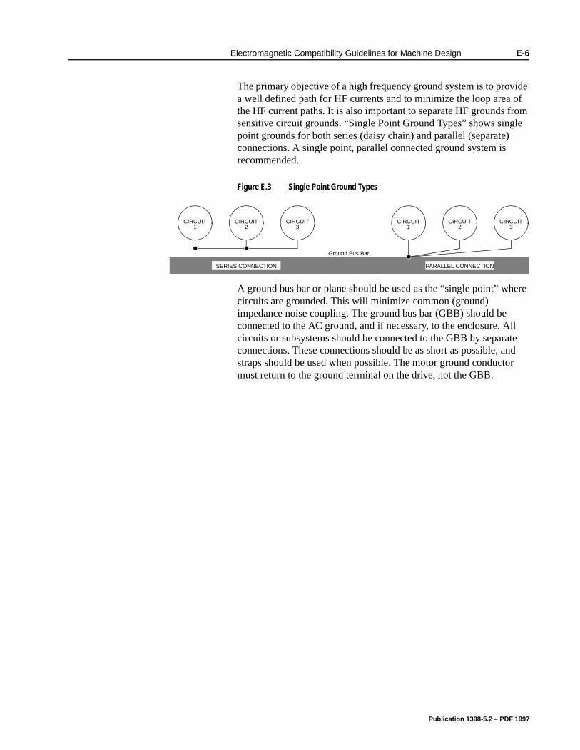
Electromagnetic Compatibility Guidelines for Machine Design E-6
le
ere
ll te nd r
The primary objective of a high frequency ground system is to provide a well defined path for HF currents and to minimize the loop area of the HF current paths. It is also important to separate HF grounds from sensitive circuit grounds. “Single Point Ground Types” shows singpoint grounds for both series (daisy chain) and parallel (separate)connections. A single point, parallel connected ground system is recommended.
A ground bus bar or plane should be used as the “single point” whcircuits are grounded. This will minimize common (ground) impedance noise coupling. The ground bus bar (GBB) should be connected to the AC ground, and if necessary, to the enclosure. Acircuits or subsystems should be connected to the GBB by separaconnections. These connections should be as short as possible, astraps should be used when possible. The motor ground conductomust return to the ground terminal on the drive, not the GBB.
Figure E.3 Single Point Ground TypesIntro
CIRCUIT1
CIRCUIT2
CIRCUIT3
CIRCUIT1
CIRCUIT2
CIRCUIT3
PARALLEL CONNECTIONSERIES CONNECTION
Ground Bus Bar
Publication 1398-5.2 – PDF 1997
E-7 Electromagnetic Compatibility Guidelines for Machine Design
”
ust
an
can ing lso
nly
s, s.
ion ded t
h
e
ure
ust
ng.
d g f the se
MC
Shielding and Segregation The EMI radiating from the drive enclosure drops off very quickly over distance. Mounting the drive in an enclosure, such as an industrial cabinet, further reduces the radiated emissions. The cabinet should have a high frequency ground and the size of the openings should be minimized. In addition, the drive is considered an “opendevice which does not provide the proper IP rating for the environment in which it is installed. For this reason the enclosure mprovide the necessary degree of protection. An IP rating or Nema rating (which is similar to IP) specifies the degree of protection thatenclosure provides.
The primary propagation route for EMI emissions from a drive is through cabling. The cables conduct the EMI to other devices, andalso radiate the EMI. For this reason, cable segregation and shieldare important factors in reducing emissions. Cable shielding can aincrease the level of immunity for a drive. For example:
Shield termination at both ends is extremely important. The common misconception that shields should be terminated at oone end originates from audio applications with frequencies <20 kHz. RF applications must be terminate the shield at both endand possibly at intermediate points for exceptionally long cable
When shielded cables are not terminated at the cable connectand pass through the wall of a cabinet, the shield must be bonto the cabinet wall to prevent noise acquired inside the cabinefrom radiating outside the cabinet, and vice versa.
When shielded cables are terminated to connectors, the shieldmust be provide complete 360° coverage and terminate througthe connector backshell. The shield must not be grounded inside the connector through a drain wire. Grounding the shield insidthe connector couples the noise on the shield to the signal conductors sharing the connector and virtually guarantees failto meet European EMC requirements.
The shield must be continuous. Each intermediate connector mcontinue the shield connection through the backshell.
All cables, both power and signal, should use twisted wire pairi
The shield termination described above provides a coaxial type ofconfiguration which provides magnetic shielding, and the shield provides a return path for HF currents that are capacitively couplefrom the motor windings to the frame. If power frequency circulatincurrents are an issue, a 250 VAC capacitor should be used at one oconnections to block 50/60 Hz current while passing HF currents. Uof a properly shielded motor cable is essential to meet European Erequirements.
The following suggestions are recommended for all installations.
Publication 1398-5.2 – PDF 1997
Electromagnetic Compatibility Guidelines for Machine Design E-8
te -
ifier.
.
n-
att
r, in
at
1. Motor cables must have a continuous shield and be terminated at both ends. The shield must connect to the ground bus bar or drive chassis at the drive end, and the motor frame at the motor end. Use of a properly shielded motor cable is essential to meet European EMC requirements.
2. Signal cables (encoder, serial, analog) should be routed away from the motor cable and power wiring. Separate steel conduit can be used to provide shielding between the signal and power wiring. Do not route signal and power wiring through common junctions or raceways.
3. Signal cables from other circuits should not pass within 300 mm (1 ft.) of the drive.
4. The length or parallel runs between other circuit cables and the motor or power cable should be minimized. A rule of thumb is 300 mm (1 ft.) of separation for each 10 m (30 ft.) of parallel run. The 30 mm (1 ft.) separation can be reduced if the parallel run is less than 1 m (3 ft.).
5. Cable intersections should always occur at right angles to mini-mize magnetic coupling.
6. The encoder mounted on the brushless servo motor should be con-nected to the amplifier with a cable using multiple twisted wire pairs and an overall cable shield. Encoder cables are offered in various lengths that have correct terminations.
Persistent EMI problems may require additional countermeasures. The following suggestions for system modification may be attempted.
1. A ferrite toroid or “doughnut” around a signal cable may attenuacommon mode noise, particularly RS-232 communication problems. However, a ferrite toroid will not help differential mode noise. Differential mode noise requires twisted wire pairs.
2. Suppress each switched inductive device near the servo amplSwitch inductive devices include solenoids, relay coils, starter coils and AC motors (such as motor driven mechanical timers)
3. DC coils should be suppressed with a “free-wheeling” diode conected across the coil.
4. AC coils should be suppressed with RC filters (a 200 Ohm ½ Wresistor in series with a 0.5 uF, 600 Volt capacitor is common).
Following these guidelines can minimize noise problems. Howeveequipment EMC performance must meet regulatory requirements various parts of the world, specifically the European Union. Ultimately, it is the responsibility of the machine builder to ensure ththe machine meets the appropriate requirements as installed.
Publication 1398-5.2 – PDF 1997

E-9 Electromagnetic Compatibility Guidelines for Machine Design
Publication 1398-5.2 – PDF 1997
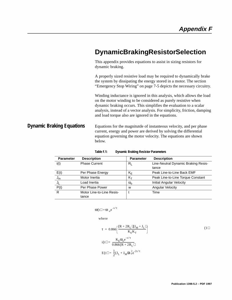
Appendix F
try.
ad
ing
e
Dynamic Braking Resistor SelectionAppendix F
This appendix provides equations to assist in sizing resistors for dynamic braking.
A properly sized resistive load may be required to dynamically brake the system by dissipating the energy stored in a motor. The section “Emergency Stop Wiring” on page 7-5 depicts the necessary circui
Winding inductance is ignored in this analysis, which allows the loon the motor winding to be considered as purely resistive when dynamic braking occurs. This simplifies the evaluation to a scalar analysis, instead of a vector analysis. For simplicity, friction, dampand load torque also are ignored in the equations.
Dynamic Braking Equations Equations for the magnitutde of instanteous velocity, and per phascurrent, energy and power are derived by solving the differential equation governing the motor velocity. The equations are shown below.
Table F.1: Dynamic Braking Resistor Parameters
Parameter Description Parameter Descriptioni(t) Phase Current RL Line-Neutral Dynamic Braking Resis-
tanceE(t) Per Phase Energy KE Peak Line-to-Line Back EMFJm Motor Inertia KT Peak Line-to-Line Torque Constant
JL Load Inertia ωo Initial Angular VelocityP(t) Per Phase Power w Angular VelocityR Motor Line-to-Line Resis-
tancet Time
Intro
ω t( ) ωoet– τ⁄
=
1( )
where
τ 0.866R 2RL+( ) JM JL+( )
KEKT-------------------------------------------------=
i t( )KEωoe
t– τ⁄
0.866 R 2RL+( )---------------------------------------=
E t( ) 12--- JL JM+( )ω2
oe2t– τ⁄
=
Publication 1398-5.2 – PDF 1997
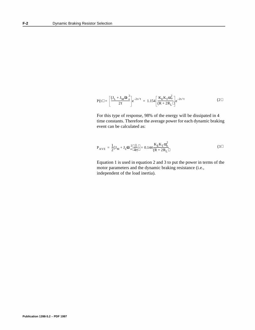
F-2 Dynamic Braking Resistor Selection
For this type of response, 98% of the energy will be dissipated in 4 time constants. Therefore the average power for each dynamic braking event can be calculated as:
Equation 1 is used in equation 2 and 3 to put the power in terms of the motor parameters and the dynamic braking resistance (i.e., independent of the load inertia).
Intro
P t( )JL JM+( )ωo
2
2τ------------------------------ e
2– t τ⁄1.154
KEKTω2o
R 2RL+( )------------------------- e
2t– τ⁄= = 2( )
Intro
3( )PAVE12--- JM JL+( )ωo
2 14τ-----
0.144KEKT ωo
2
R 2RL+( )-------------------------==
Publication 1398-5.2 – PDF 1997
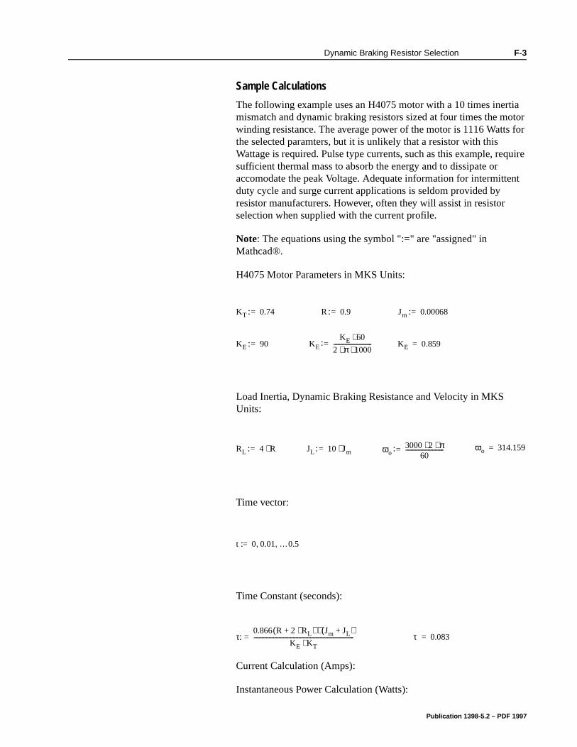
Dynamic Braking Resistor Selection F-3
Sample Calculations
The following example uses an H4075 motor with a 10 times inertia mismatch and dynamic braking resistors sized at four times the motor winding resistance. The average power of the motor is 1116 Watts for the selected paramters, but it is unlikely that a resistor with this Wattage is required. Pulse type currents, such as this example, require sufficient thermal mass to absorb the energy and to dissipate or accomodate the peak Voltage. Adequate information for intermittent duty cycle and surge current applications is seldom provided by resistor manufacturers. However, often they will assist in resistor selection when supplied with the current profile.
Note: The equations using the symbol ":=" are "assigned" in Mathcad®.
H4075 Motor Parameters in MKS Units:
Load Inertia, Dynamic Braking Resistance and Velocity in MKS Units:
Time vector:
Time Constant (seconds):
Current Calculation (Amps):
Instantaneous Power Calculation (Watts):
Intro
KE 90=
KT 0.74= R 0.9= Jm 0.00068=
KE
KE 60⋅2 π 1000⋅ ⋅---------------------------= KE 0.859=
:
: :
: :
Intro
RL 4 R⋅= JL 10 Jm⋅= ωo3000 2 π⋅ ⋅
60---------------------------= ωo 314.159=: : :
Intro
t 0 0.01 …0.5, ,=:
Intro
τ0.866 R 2 RL⋅+( ) Jm JL+( )⋅
KE KT⋅-----------------------------------------------------------------------= τ 0.083=:
Publication 1398-5.2 – PDF 1997
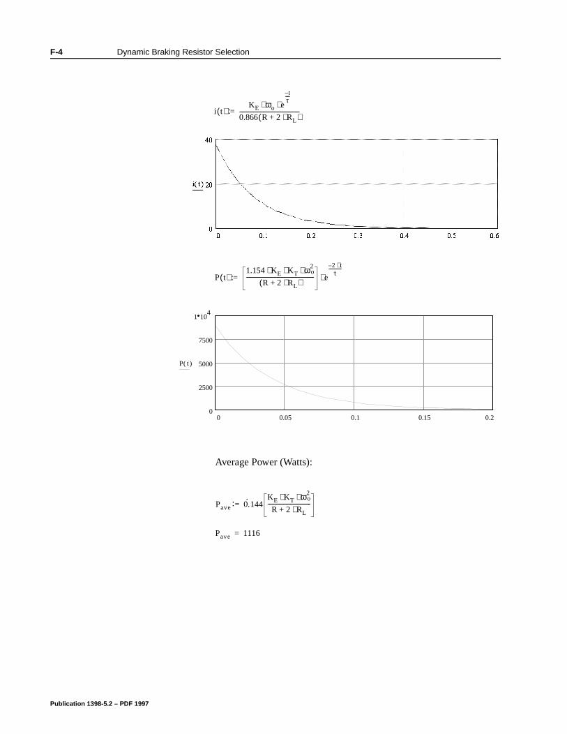
F-4 Dynamic Braking Resistor Selection
Average Power (Watts):
Intro
Intro
i t( )KE ωo e
t–τ----
⋅ ⋅0.866 R 2 RL⋅+( )-------------------------------------------=:
P( )t .R .2 R L
e
0 0.05 0.1 0.15 0.20
2500
5000
7500
1 104
P( )t
P t( )1.154 KE KT ω2
o⋅ ⋅ ⋅R 2+ RL⋅( )
------------------------------------------------- e
2– t⋅τ
------------
⋅=:
Intro
Pave 0.·
144KE KT ω2
o⋅ ⋅R 2 RL⋅+
-------------------------------=
Pave 1116=
:
Publication 1398-5.2 – PDF 1997
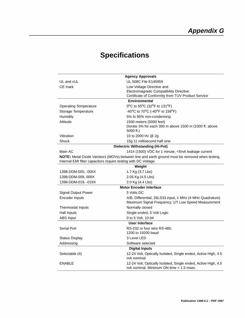
Appendix G
Specifications Appendix G
Agency ApprovalsUL and cUL UL 508C File E145959CE mark Low Voltage Directive and
Electromagnetic Compatibility Directive Certificate of Conformity from TUV Product ServiceEnvironmental
Operating Temperature 0oC to 55oC (32oF to 131oF)
Storage Temperature -40oC to 70oC (-40oF to 158oF)Humidity 5% to 95% non-condensing Altitude 1500 meters (5000 feet)
Derate 3% for each 300 m above 1500 m (1000 ft. above 5000 ft.)
Vibration 10 to 2000 Hz @ 2gShock 15g 11 millisecond half sine
Dielectric Withstanding (Hi-Pot)Main AC 1414 (1500) VDC for 1 minute, <5mA leakage currentNOTE: Metal Oxide Varistors (MOVs) between line and earth ground must be removed when testing. Internal EMI filter capacitors require testing with DC Voltage.
Weight1398-DDM-005, -005X 1.7 Kg (3.7 Lbs) 1398-DDM-009, 009X 2.05 Kg (4.5 Lbs)1398-DDM-019, -019X 2.0 Kg (4.4 Lbs)
Motor Encoder InterfaceSignal Output Power 5 Volts DCEncoder Inputs A/B, Differential, 26LS33 input, 1 MHz (4 MHz Quadrature)
Maximum Signal Frequency, 1/T Low Speed MeasurementThermostat Inputs Normally closed
Hall Inputs Single-ended, 5 Volt LogicABS Input 0 to 5 Volt, 10-bit
User InterfaceSerial Port RS-232 or four wire RS-485,
1200 to 19200 baud
Status Display 3 Level LEDAddressing Software selected
Digital InputsSelectable (4) 12-24 Volt, Optically Isolated, Single ended, Active High, 4.5
mA nominal
ENABLE 12-24 Volt, Optically Isolated, Single ended, Active High, 4.5 mA nominal. Minimum ON time = 1.5 msec.
Publication 1398-5.2 – PDF 1997
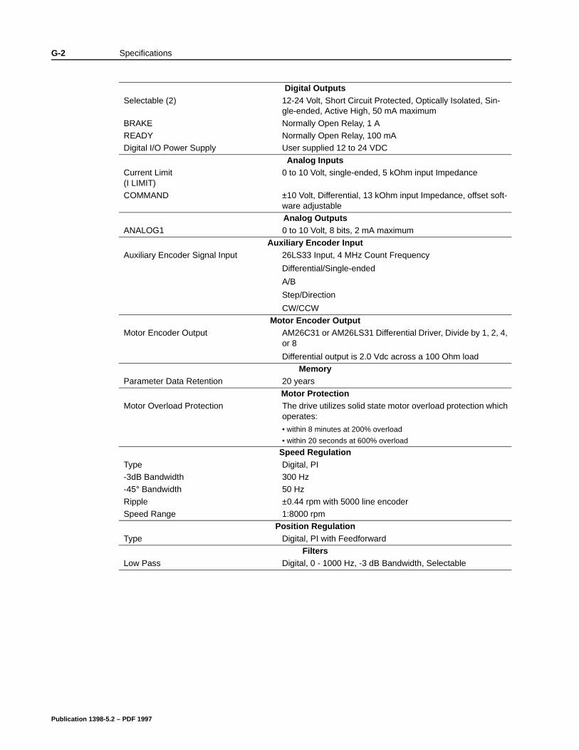
G-2 Specifications
Digital OutputsSelectable (2) 12-24 Volt, Short Circuit Protected, Optically Isolated, Sin-
gle-ended, Active High, 50 mA maximum
BRAKE Normally Open Relay, 1 AREADY Normally Open Relay, 100 mADigital I/O Power Supply User supplied 12 to 24 VDC
Analog InputsCurrent Limit (I LIMIT)
0 to 10 Volt, single-ended, 5 kOhm input Impedance
COMMAND ±10 Volt, Differential, 13 kOhm input Impedance, offset soft-ware adjustableAnalog Outputs
ANALOG1 0 to 10 Volt, 8 bits, 2 mA maximum
Auxiliary Encoder InputAuxiliary Encoder Signal Input 26LS33 Input, 4 MHz Count Frequency
Differential/Single-ended
A/B
Step/Direction
CW/CCWMotor Encoder Output
Motor Encoder Output AM26C31 or AM26LS31 Differential Driver, Divide by 1, 2, 4, or 8
Differential output is 2.0 Vdc across a 100 Ohm loadMemory
Parameter Data Retention 20 years
Motor ProtectionMotor Overload Protection The drive utilizes solid state motor overload protection which
operates:
• within 8 minutes at 200% overload
• within 20 seconds at 600% overload
Speed RegulationType Digital, PI-3dB Bandwidth 300 Hz-45° Bandwidth 50 Hz
Ripple ±0.44 rpm with 5000 line encoderSpeed Range 1:8000 rpm
Position RegulationType Digital, PI with Feedforward
FiltersLow Pass Digital, 0 - 1000 Hz, -3 dB Bandwidth, Selectable
Publication 1398-5.2 – PDF 1997
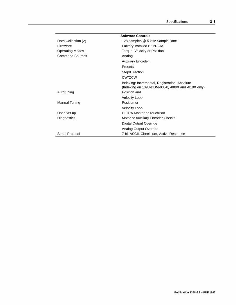
Specifications G-3
Software ControlsData Collection (2) 128 samples @ 5 kHz Sample RateFirmware Factory installed EEPROMOperating Modes Torque, Velocity or Position
Command Sources Analog
Auxiliary Encoder
Presets
Step/Direction
CW/CCW
Indexing: Incremental, Registration, Absolute(Indexing on 1398-DDM-005X, -009X and -019X only)
Autotuning Position and
Velocity LoopManual Tuning Position or
Velocity LoopUser Set-up ULTRA Master or TouchPadDiagnostics Motor or Auxiliary Encoder Checks
Digital Output Override
Analog Output OverrideSerial Protocol 7-bit ASCII, Checksum, Active Response
Publication 1398-5.2 – PDF 1997
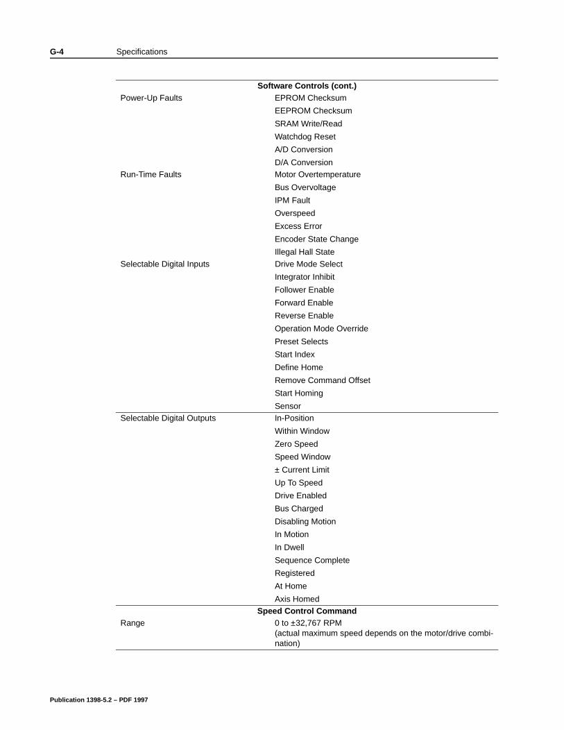
G-4 Specifications
Software Controls (cont.)Power-Up Faults EPROM Checksum
EEPROM Checksum
SRAM Write/Read
Watchdog Reset
A/D Conversion
D/A ConversionRun-Time Faults Motor Overtemperature
Bus Overvoltage
IPM Fault
Overspeed
Excess Error
Encoder State Change
Illegal Hall State
Selectable Digital Inputs Drive Mode Select
Integrator Inhibit
Follower Enable
Forward Enable
Reverse Enable
Operation Mode Override
Preset Selects
Start Index
Define Home
Remove Command Offset
Start Homing
SensorSelectable Digital Outputs In-Position
Within Window
Zero Speed
Speed Window
± Current Limit
Up To Speed
Drive Enabled
Bus Charged
Disabling Motion
In Motion
In Dwell
Sequence Complete
Registered
At Home
Axis HomedSpeed Control Command
Range 0 to ±32,767 RPM(actual maximum speed depends on the motor/drive combi-nation)
Publication 1398-5.2 – PDF 1997
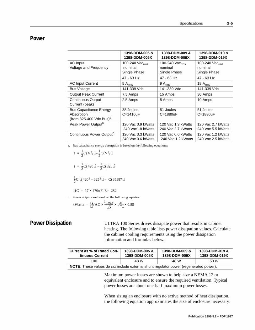
Specifications G-5
Power
Power Dissipation ULTRA 100 Series drives dissipate power that results in cabinet heating. The following table lists power dissipation values. Calculate the cabinet cooling requirements using the power dissipation information and formulas below.
Maximum power losses are shown to help size a NEMA 12 or equivalent enclosure and to ensure the required ventilation. Typical power losses are about one-half maximum power losses.
When sizing an enclosure with no active method of heat dissipation, the following equation approximates the size of enclosure necessary:
1398-DDM-005 & 1398-DDM-005X
1398-DDM-009 & 1398-DDM-009X
1398-DDM-019 & 1398-DDM-019X
AC Input Voltage and Frequency
100-240 Vacrms nominalSingle Phase
47 - 63 Hz
100-240 Vacrmsnominal Single Phase
47 - 63 Hz
100-240 Vacrmsnominal Single Phase
47 - 63 HzAC Input Current 5 Arms 9 Arms 18 Arms
Bus Voltage 141-339 Vdc 141-339 Vdc 141-339 Vdc
Output Peak Current 7.5 Amps 15 Amps 30 AmpsContinuous Output Current (peak)
2.5 Amps 5 Amps 10 Amps
Bus Capacitance Energy Absorption (from 325-400 Vdc Bus)a
38 JoulesC=1410uF
51 JoulesC=1880uF
51 JoulesC=1880uF
Peak Power Outputb 120 Vac 0.9 kWatts 240 Vac1.8 kWatts
120 Vac 1.3 kWatts240 Vac 2.7 kWatts
120 Vac 2.7 kWatts240 Vac 5.5 kWatts
Continuous Power Outputb 120 Vac 0.3 kWatts240 Vac 0.6 kWatts
120 Vac 0.6 kWatts 240 Vac 1.2 kWatts
120 Vac 1.2 kWatts240 Vac 2.5 kWatts
a. Bus capacitance energy absorption is based on the following equations:
b. Power outputs are based on the following equation:
ε 12---C V2
f( ) 12---C V2
i( )–=
ε 12---C 420( )2 1
2---C 325( )2–=
12---C 4202 3252–( )⋅ C 35387( )=
ifC 17 470uF× E 282=,=
kWatts VACIRmax
2--------------× 3×
0.85×=
Current as % of Rated Con-tinuous Current
1398-DDM-005 &1398-DDM-005X
1398-DDM-009 &1398-DDM-009X
1398-DDM-019 &1398-DDM-019X
100 48 W 48 W 50 WNOTE: These values do not include external shunt regulator power (regenerated power).
Publication 1398-5.2 – PDF 1997

G-6 Specifications
T = 4.08 * (Q/A) + 1.1
where:
T = Temperature difference between inside air and outside ambient (°F)
Q = Heat generated in enclosure (watts)
A = Enclosure surface area in ft.2 = (2dw + 2dh + 2wh) / 144
d = Depth in inches
h = Height in inches
w = Width in inches
Publication 1398-5.2 – PDF 1997
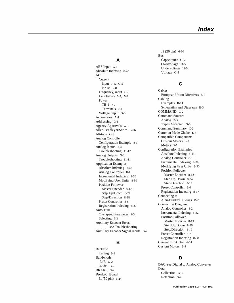
Index
HelpIndex
AABS Input G-1Absolute Indexing 8-43AC
Currentinput 7-8, G-5inrush 7-8
Frequency, input G-5Line Filters 5-7, 5-8Power
TB-1 7-7Terminals 7-1
Voltage, input G-5Accessories A-1Addressing G-1Agency Approvals G-1Allen-Bradley 9/Series B-26Altitude G-1Analog Controller
Configuration Example 8-1Analog Inputs 3-4
Troubleshooting 11-12Analog Outputs G-2
Troubleshooting 11-11Application Examples
Absolute Indexing 8-43Analog Controller 8-1Incremental Indexing 8-30Modifying User Units 8-50Position Follower
Master Encoder 8-12Step Up/Down 8-24Step/Direction 8-18
Preset Controller 8-6Registration Indexing 8-37
Auto TuneOverspeed Parameter 9-5Selecting 9-3
Auxiliary Encoder Error, see Troubleshooting
Auxiliary Encoder Signal Inputs G-2
BBacklash
Tuning 9-3Bandwidth
-3dB G-2-45dB G-2
BRAKE G-2Breakout Board
J1 (50 pin) 6-24
J2 (26 pin) 6-30Bus
Capacitance G-5Overvoltage 11-5Undervoltage 11-5Voltage G-5
CCables
European Union Directives 5-7Cabling
Examples B-24Schematics and Diagrams B-3
COMMAND G-2Command Sources
Analog 3-3Types Accepted G-3
Command Summary C-3Common Mode Choke E-5Compatible Components
Custom Motors 3-8Motors 3-7
Configuration ExamplesAbsolute Indexing 8-43Analog Controller 8-1Incremental Indexing 8-30Modifying User Units 8-50Position Follower
Master Encoder 8-12Step Up/Down 8-24Step/Direction 8-18
Preset Controller 8-6Registration Indexing 8-37
Connecting toAlen-Bradley 9/Series B-26
Connection DiagramAnalog Controller 8-2Incremental Indexing 8-32Position Follower
Master Encoder 8-13Step Up/Down 8-25Step/Direction 8-19
Preset Controller 8-7Registration Indexing 8-38
Current Limit 3-4, 6-14Custom Motors 3-8
DDAC, see Digital to Analog ConverterData
Collection G-3Retention G-2
Publication 1398-5.2 – PDF 1997
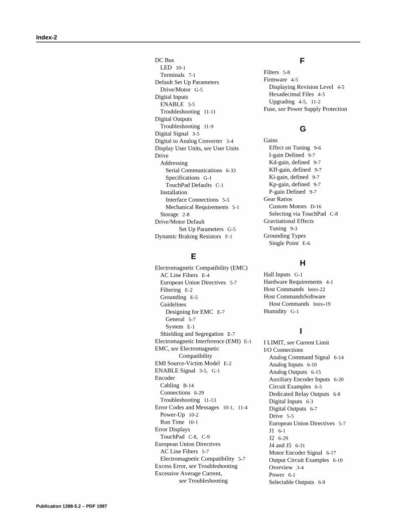
Index-2
DC BusLED 10-1Terminals 7-1
Default Set Up ParametersDrive/Motor G-5
Digital InputsENABLE 3-5Troubleshooting 11-11
Digital OutputsTroubleshooting 11-9
Digital Signal 3-5Digital to Analog Converter 3-4Display User Units, see User UnitsDrive
AddressingSerial Communications 6-33Specifications G-1TouchPad Defaults C-1
InstallationInterface Connections 5-5Mechanical Requirements 5-1
Storage 2-8Drive/Motor Default
Set Up Parameters G-5Dynamic Braking Resistors F-1
EElectromagnetic Compatibility (EMC)
AC Line Filters E-4European Union Directives 5-7Filtering E-2Grounding E-5Guidelines
Designing for EMC E-7General 5-7System E-1
Shielding and Segregation E-7Electromagnetic Interference (EMI) E-1EMC, see Electromagnetic
CompatibilityEMI Source-Victim Model E-2ENABLE Signal 3-5, G-1Encoder
Cabling B-14Connections 6-29Troubleshooting 11-13
Error Codes and Messages 10-1, 11-4Power-Up 10-2Run Time 10-1
Error DisplaysTouchPad C-8, C-9
European Union DirectivesAC Line Filters 5-7Electromagnetic Compatibility 5-7
Excess Error, see TroubleshootingExcessive Average Current,
see Troubleshooting
FFilters 5-8Firmware 4-5
Displaying Revision Level 4-5Hexadecimal Files 4-5Upgrading 4-5, 11-2
Fuse, see Power Supply Protection
GGains
Effect on Tuning 9-6I-gain Defined 9-7Kd-gain, defined 9-7Kff-gain, defined 9-7Ki-gain, defined 9-7Kp-gain, defined 9-7P-gain Defined 9-7
Gear RatiosCustom Motors D-16Selecting via TouchPad C-8
Gravitational EffectsTuning 9-3
Grounding TypesSingle Point E-6
HHall Inputs G-1Hardware Requirements 4-1Host Commands Intro-22Host CommandsSoftware
Host Commands Intro-19Humidity G-1
II LIMIT, see Current LimitI/O Connections
Analog Command Signal 6-14Analog Inputs 6-10Analog Outputs 6-15Auxiliary Encoder Inputs 6-20Circuit Examples 6-5Dedicated Relay Outputs 6-8Digital Inputs 6-3Digital Outputs 6-7Drive 5-5European Union Directives 5-7J1 6-1J2 6-29J4 and J5 6-31Motor Encoder Signal 6-17Output Circuit Examples 6-10Overview 3-4Power 6-1Selectable Outputs 6-9
Publication 1398-5.2 – PDF 1997
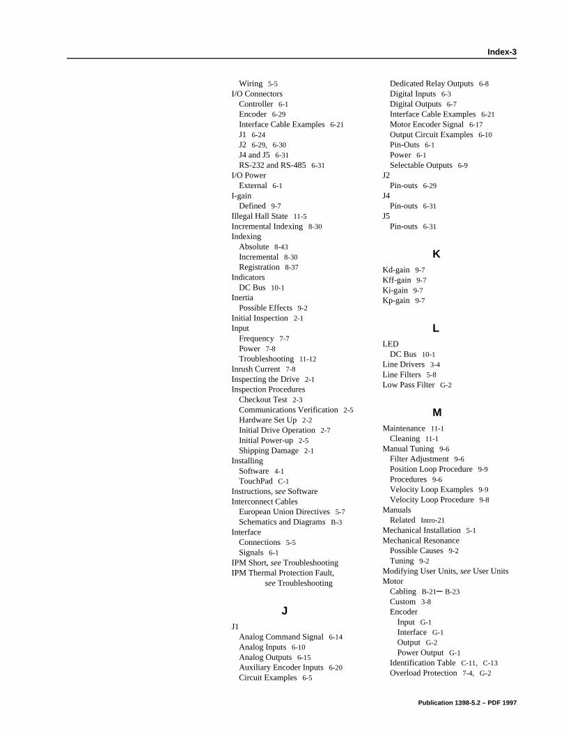
Index-3
Wiring 5-5I/O Connectors
Controller 6-1Encoder 6-29Interface Cable Examples 6-21J1 6-24J2 6-29, 6-30J4 and J5 6-31RS-232 and RS-485 6-31
I/O PowerExternal 6-1
I-gainDefined 9-7
Illegal Hall State 11-5Incremental Indexing 8-30Indexing
Absolute 8-43Incremental 8-30Registration 8-37
IndicatorsDC Bus 10-1
InertiaPossible Effects 9-2
Initial Inspection 2-1Input
Frequency 7-7Power 7-8Troubleshooting 11-12
Inrush Current 7-8Inspecting the Drive 2-1Inspection Procedures
Checkout Test 2-3Communications Verification 2-5Hardware Set Up 2-2Initial Drive Operation 2-7Initial Power-up 2-5Shipping Damage 2-1
InstallingSoftware 4-1TouchPad C-1
Instructions, see SoftwareInterconnect Cables
European Union Directives 5-7Schematics and Diagrams B-3
InterfaceConnections 5-5Signals 6-1
IPM Short, see TroubleshootingIPM Thermal Protection Fault,
see Troubleshooting
JJ1
Analog Command Signal 6-14Analog Inputs 6-10Analog Outputs 6-15Auxiliary Encoder Inputs 6-20Circuit Examples 6-5
Dedicated Relay Outputs 6-8Digital Inputs 6-3Digital Outputs 6-7Interface Cable Examples 6-21Motor Encoder Signal 6-17Output Circuit Examples 6-10Pin-Outs 6-1Power 6-1Selectable Outputs 6-9
J2Pin-outs 6-29
J4Pin-outs 6-31
J5Pin-outs 6-31
KKd-gain 9-7Kff-gain 9-7Ki-gain 9-7Kp-gain 9-7
LLED
DC Bus 10-1Line Drivers 3-4Line Filters 5-8Low Pass Filter G-2
MMaintenance 11-1
Cleaning 11-1Manual Tuning 9-6
Filter Adjustment 9-6Position Loop Procedure 9-9Procedures 9-6Velocity Loop Examples 9-9Velocity Loop Procedure 9-8
ManualsRelated Intro-21
Mechanical Installation 5-1Mechanical Resonance
Possible Causes 9-2Tuning 9-2
Modifying User Units, see User UnitsMotor
Cabling B-21– B-23Custom 3-8Encoder
Input G-1Interface G-1Output G-2Power Output G-1
Identification Table C-11, C-13Overload Protection 7-4, G-2
Publication 1398-5.2 – PDF 1997
Index-4
Overview 3-7Phase Connections 7-2Power
Cabling 7-2Troubleshooting
Encoder Error 11-6Motor Information Missing 11-7Overspeed 11-6Overtemperature 11-4Thermal Protection Fault 11-6
Mounting Requirements 5-1
OOperating Temperature G-1Options A-1Output Current
Continuous (peak) G-5Peak G-5
PPart Numbers A-1
AC Line Filters A-2Cables B-3Encoder Cables A-3, B-14Fuses A-1Interface Cables A-1Manuals A-2Mating Connectors A-6Motor Power Cables A-4, B-21Serial Interface Cables A-3, B-13Shunt Resistor A-2Terminal Strip A-2TouchPad A-2
PC Display Units Dialog 8-50P-gain
Defined 9-7Position Follower
Master Encoder 8-12Step Up/Down 8-24Step/Direction 8-18
Position Regulation G-2Power
Input Frequency 7-7Output
Continuous G-5Peak G-5
Protection 7-5Ratings G-5Source Separation 7-8Supply 7-5
Preset Binary InputsProgrammable Speed Inputs 8-6
Preset ControllerConfiguration Example 8-6
Protection Circuitry 7-5Motor Overload 7-4
PublicationsRelated Intro-21
RReadme File 4-5READY G-2Registration Indexing 8-37Requirements
AC Input Current 7-8I/O Power
External 6-1Input Power 7-8Transformer 7-8Wire Size 7-8
Revision LevelSoftware 4-4
RippleSpeed Regulation G-2
RS-232Multiple Axes Set-up 6-38Single Axis Set-up 6-34Troubleshooting 11-8
RS-485Multiple Axes Set-up 6-35
Run TimeError Codes 10-1Faults G-4
SSafety
Guidelines 1-1Safety Notes
User Responsibilities 1-1Sample Applications
Absolute Indexing 8-43Analog Controller 8-1Incremental Indexing 8-30Modifying User Units 8-50Position Follower
Master Encoder 8-12Step Up/Down 8-24Step/Direction 8-18
Preset Controller 8-6Registration Indexing 8-37
Selectable I/O G-1, G-2Digital Inputs G-4Digital Outputs G-4
Self-Test C-2Separation of Power Sources 7-8Serial Communications
Drive Addressing 6-33, 6-34RS-232 Multiple Axes 6-38RS-232 Single Axis 6-34RS-485 Multiple Axes 6-35
Hardware Addressing 6-33Overview 3-3
Publication 1398-5.2 – PDF 1997
Index-5
Port (J5) 6-31Serial Interface Cables
Schematics and Diagrams B-13Serial Ports G-1Serial Protocol G-3Shipping Damage 2-1Shock G-1Signal Extension Kits 6-1Single Point Ground Example E-6Software
Host Commands Intro-22Installation 4-1Instructions Intro-19Readme File 4-5Requirements 4-1Starting and Quitting 4-2Version Level 4-4
Space Requirements 5-1Specifications G-1, G-5
ABS Input G-1AC Input
Current G-5Frequency G-5
AC Voltage G-5Addressing G-1Agency Approvals G-1Altitude G-1Analog Outputs G-2Auxiliary Encoder Signal Inputs G-2BRAKE G-2Bus Capacitance G-5Bus Voltage G-5COMMAND G-2Command Sources G-3Data Collection G-3Data Retention G-2ENABLE G-1Hall Inputs G-1Humidity G-1Low Pass Filter G-2Motor Encoder
Input G-1Interface G-1Output G-2Signal Output Power G-1
Operating Temperature G-1Output Current
Continuous (peak) G-5Peak G-5
Position Regulation G-2Power Output
Continuous G-5Peak G-5
Power-Up Faults G-4READY G-2Ripple
Speed Regulation G-2Run-Time Faults G-4Selectable Digital Inputs G-4
Selectable Digital Outputs G-2, G-4Selectable Inputs G-1Serial Ports G-1Serial Protocol G-3Shock G-1Speed Control Command G-4Speed Regulation G-2
-3dB Bandwidth G-2-45dB Bandwidth G-2
Status Display G-1Storage Temperature G-1Thermostat Inputs G-1Vibration G-1Weight G-1
Speed Control Command G-4Speed Regulation G-2Starting and Quitting
Software 4-2Status Display G-1Storage Intro-17Storage Temperature G-1Storing the Drive 2-8Support
Local Product Intro-19Technical Product Assistance Intro-19
Symbols and Conventions Intro-23
TTB-1
AC Power Terminals 7-1Bus Terminals
AC Power 7-7DC Bus Terminals 7-1Motor Power Terminals 7-2
Terminal StripJ1 (50 pin) 6-24J2 (26 pin) 6-30see also TB-1
Testing the Drive 2-2Thermostat Inputs G-1Timing Diagram
Absolute Indexing 8-43Incremental Indexing 8-30Registration Indexing 8-37
Torque (Current) Loop Diagram 9-3TouchPad C-2, C-3
Character Selection C-7Cursor Movements C-7Default Settings C-1Drive Addressing Defaults C-1Error Display C-9Error Displays C-8Gear Ratios C-8Installation and Operation C-1Instructions Intro-19Lists
Baud Rate C-16Drive Communications C-16
Publication 1398-5.2 – PDF 1997
Index-6
Motor Table C-11, C-13Selections C-7
Modes of Operation C-3Motor Selection C-6Motor Table Identification C-11, C-
13Revision Level 4-5Text Selection C-7Version Display C-2Warnings C-8
Transformer Sizing 7-8Troubleshooting 11-1
Analog Outputs 11-11Auxiliary Encoder Error 11-6Bus Overvoltage 11-5Bus Undervoltage 11-5Current Limit 11-12Digital Inputs 11-11Digital Outputs 11-9Encoder Inputs 11-13Excess Error 11-6Excessive Average Current 11-5Gain Adjustments 9-2IPM Short 11-4IPM Thermal Protection Fault 11-6Motor Buzz or Squeal 9-2Motor Encoder Error 11-6Motor Overspeed 11-6Motor Overtemperature 11-4Motor Thermal Protection Fault 11-6RS-232 Communications 11-8TouchPad C-8
Tuning 9-1Auto Tune 9-3Backlash 9-3Gain Settings, Effect on 9-6General 9-1Gravitational Effects 9-3High Inertia Loads 9-1Manual Tune 9-6Mechanical Resonance 9-2
Tuning ProceduresManual Mode 9-6
Position Loop 9-9Velocity Loop 9-8Velocity Loop Examples 9-9
Velocity LoopFilter 9-6Overspeed Parameter 9-5
Typographical Conventions Intro-23
UULTRA Master, see SoftwareUnpacking the Drive 2-1User Units 8-50
VVelocity Loop Diagram 9-2Version Level
Firmware 4-5Software 4-4TouchPad C-2
Vibration G-1
WWarnings
TouchPad C-8Weight G-1Wire Size 7-8Wiring I/O 5-5Wording Conventions Intro-23
Publication 1398-5.2 – PDF 1997


Publication 1398-5.2 – PDF 1997 PN 0013-1042-002 Rev ACopyright 1997 Allen-Bradley Company, Inc. Printed in USA