ultra-long duration balloon (uldb) program study · ultra-long duration balloon (uldb) program...
TRANSCRIPT
Ultra-Long Duration Balloon (ULDB)Program Study
Interim Report
Prepared for:
The Space Sciences DirectorateApril, 97
By:The GSFC Study Team
Please send comments to ITMI [email protected]: (301) 459-7425 • Fax: (301) 459-7466 •
Table of Contents
• Purpose Of This Report
• Background, Goal, And Organization
• Summary Of Current Information
• Technical Challenges
• Other Issues–Beyond The Scope Of This Study But Impacting The Program
• Summary List Of Technologies Under Consideration
• Next steps
2ULDBP Integrated Study Team Interim Report April 97

Purpose
The purpose of this interim report is to:• document requirements information,• identify technical challenges of the Ultra-Long Duration Balloon Program,• provide input to the demonstration program at Wallops and• provide information to non-balloon scientists and engineers regarding differences between
balloon and space missions and potential opportunities for science.
3ULDBP Integrated Study Team Interim Report April 97

Background, Goal and Organization
The ULDB Program study was initiated by NASA Headquarters in June 1996. Thereare three distinct but related projects currently underway. They are:
1. ULDB (≥100 day flight) Study: This is a science feasibility study to evaluatewhether science goals can be met and to identify technical challenges to satisfyscience needs.
2. The Demonstration Program: This is the initial ~100 day balloon flightdemonstrating the capability of superpressure balloons and the type of science thatcan be accomplished. This will also show the technology available to successfullyundertake such missions in the future.
3. Mission/Program: An Ultra-Long Duration Balloon Program will be the result ofa successful demonstration program.
4ULDBP Integrated Study Team Interim Report April 97
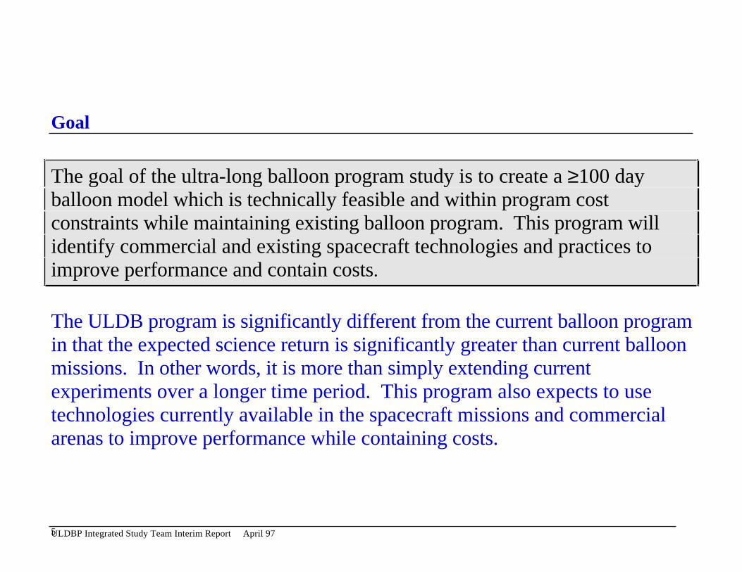
Goal
The goal of the ultra-long balloon program study is to create a ≥100 dayballoon model which is technically feasible and within program costconstraints while maintaining existing balloon program. This program willidentify commercial and existing spacecraft technologies and practices toimprove performance and contain costs.
The ULDB program is significantly different from the current balloon programin that the expected science return is significantly greater than current balloonmissions. In other words, it is more than simply extending currentexperiments over a longer time period. This program also expects to usetechnologies currently available in the spacecraft missions and commercialarenas to improve performance while containing costs.
5ULDBP Integrated Study Team Interim Report April 97
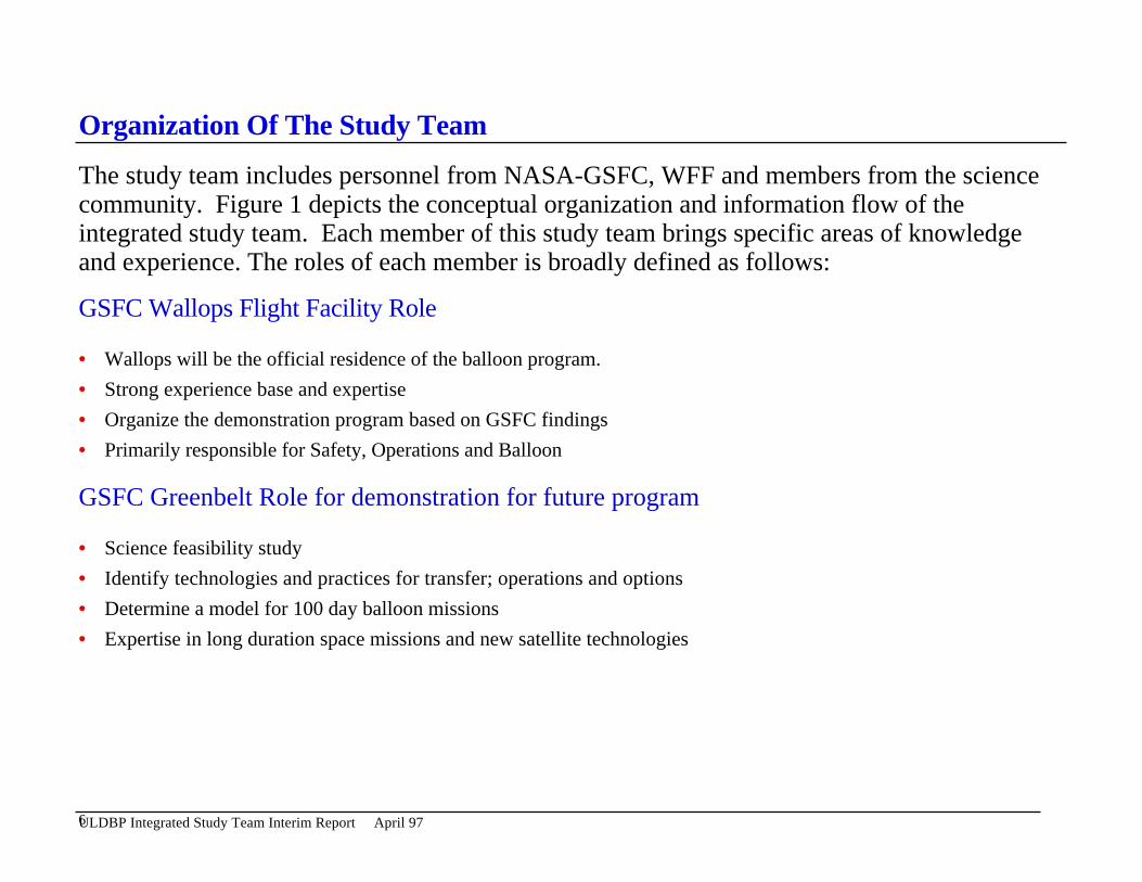
Organization Of The Study Team
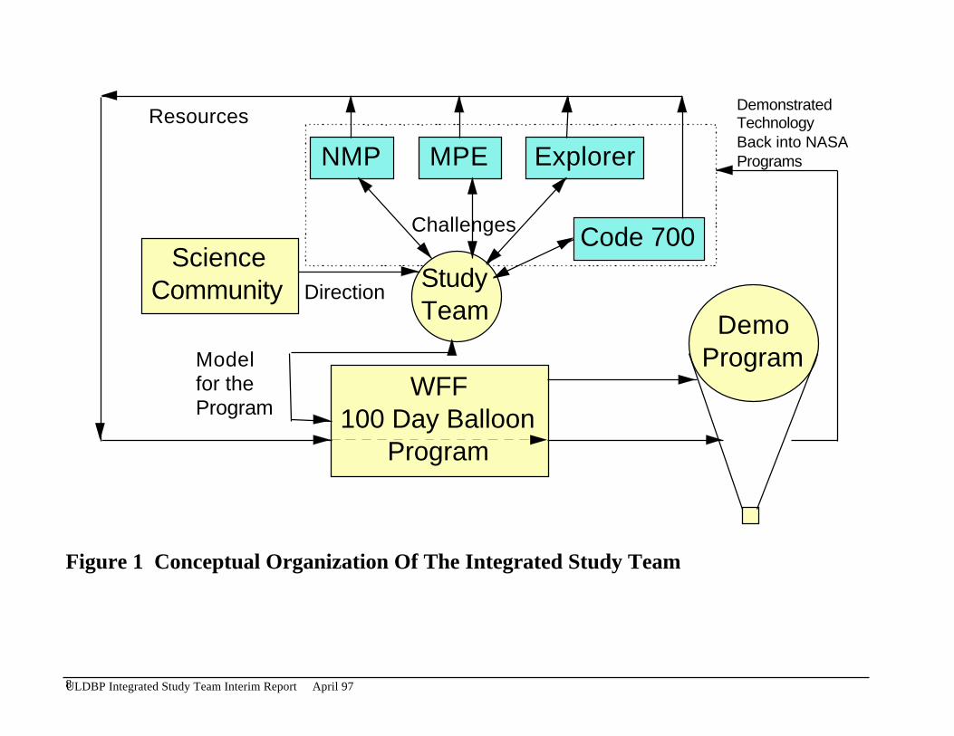
The study team includes personnel from NASA-GSFC, WFF and members from the sciencecommunity. Figure 1 depicts the conceptual organization and information flow of theintegrated study team. Each member of this study team brings specific areas of knowledgeand experience. The roles of each member is broadly defined as follows:
GSFC Wallops Flight Facility Role
• Wallops will be the official residence of the balloon program.
• Strong experience base and expertise
• Organize the demonstration program based on GSFC findings
• Primarily responsible for Safety, Operations and Balloon
GSFC Greenbelt Role for demonstration for future program
• Science feasibility study
• Identify technologies and practices for transfer; operations and options
• Determine a model for 100 day balloon missions
• Expertise in long duration space missions and new satellite technologies
6ULDBP Integrated Study Team Interim Report April 97

Organization Of The Study Team (Continued)
• Primary responsibility for recommending Communications Options, Power, Thermal, Pointing and InterfaceStandards
Science Community
• Provide requirements for strawman missions
• Provide feedback regarding technology options
• Direct and redirect study
NASA Headquarters
• Oversee and facilitate international aspects of the ULDB Program.• Plan for and coordinate infrastructure supports, e.g., TDRSS.
7ULDBP Integrated Study Team Interim Report April 97
ScienceCommunity Study
Team
NMP MPE Explorer
Code 700
WFF100 Day Balloon
Program
DemoProgram
Direction
Challenges
Modelfor theProgram
ResourcesDemonstratedTechnologyBack into NASAPrograms
Figure 1 Conceptual Organization Of The Integrated Study Team
8ULDBP Integrated Study Team Interim Report April 97
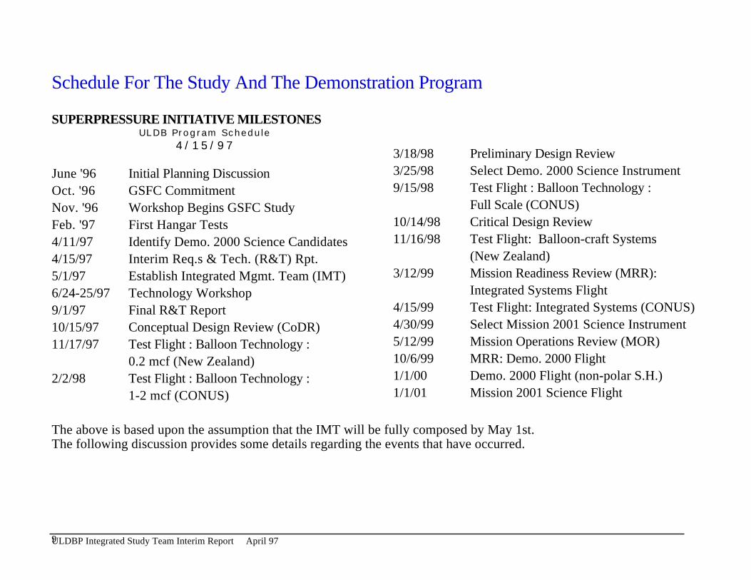
Schedule For The Study And The Demonstration Program
SUPERPRESSURE INITIATIVE MILESTONESULDB Program Schedule
4/15/973/18/98 Preliminary Design Review3/25/98 Select Demo. 2000 Science InstrumentJune '96 Initial Planning Discussion9/15/98 Test Flight : Balloon Technology :Oct. '96 GSFC Commitment
Full Scale (CONUS)Nov. '96 Workshop Begins GSFC Study10/14/98 Critical Design ReviewFeb. '97 First Hangar Tests11/16/98 Test Flight: Balloon-craft Systems4/11/97 Identify Demo. 2000 Science Candidates
(New Zealand)4/15/97 Interim Req.s & Tech. (R&T) Rpt.3/12/99 Mission Readiness Review (MRR):5/1/97 Establish Integrated Mgmt. Team (IMT)
Integrated Systems Flight6/24-25/97 Technology Workshop4/15/99 Test Flight: Integrated Systems (CONUS)9/1/97 Final R&T Report4/30/99 Select Mission 2001 Science Instrument10/15/97 Conceptual Design Review (CoDR)5/12/99 Mission Operations Review (MOR)11/17/97 Test Flight : Balloon Technology :10/6/99 MRR: Demo. 2000 Flight0.2 mcf (New Zealand)1/1/00 Demo. 2000 Flight (non-polar S.H.)2/2/98 Test Flight : Balloon Technology :1/1/01 Mission 2001 Science Flight1-2 mcf (CONUS)
The above is based upon the assumption that the IMT will be fully composed by May 1st.The following discussion provides some details regarding the events that have occurred.
9ULDBP Integrated Study Team Interim Report April 97
100 day balloon workshop Oct. 31, 1996-Nov. 1, 1996
• A workshop was organized to introduce the 100 day balloon program concept and study to the science community.Personnel from NASA HQ and GSFC (Greenbelt and WFF) participated in interactions with the science communityto generate new concepts and requirements.
• The workshop was organized into “splinter groups” based on science discipline. Five splinter groups were formed:Atmospheric Science, Cosmic Ray, Gamma Ray, Infra Red and Solar Ray.
• The splinter groups were asked to develop ideas and specific requirements for strawman missions. These strawmanmissions had to define science that is not achievable under the current balloon program and identify enablingtechnologies important to other NASA missions such as the New Millennium, Mission to Planet Earth and theexplorers and incorporate them into Long Duration Balloon missions to test them. The splinter groups were asked toprovide the following information for each strawman mission.
• Weight• Altitude Range• Power and power profile• Thermal requirements• Pointing knowledge and stability• Location of balloon, launch and desired drift• Data return requirements• Commanding requirements• PI operated or otherwise
10ULDBP Integrated Study Team Interim Report April 97
Summary Of Results From The Workshop
A summary of expected performance requirements collected from workshop participants have been summarizedin the following tables and charts.
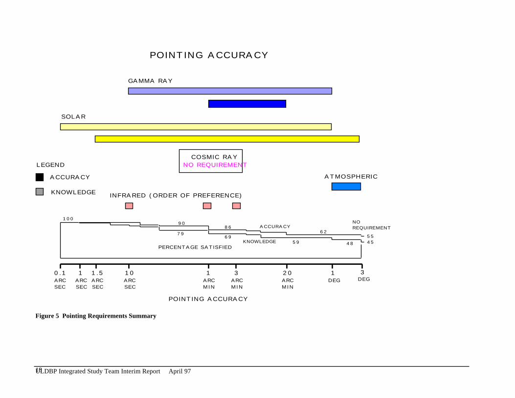
Tables 1 and 2 are the collection of Strawman mission requirements from the science community.
Table 3 is a summary tabulation of the communications requirements.
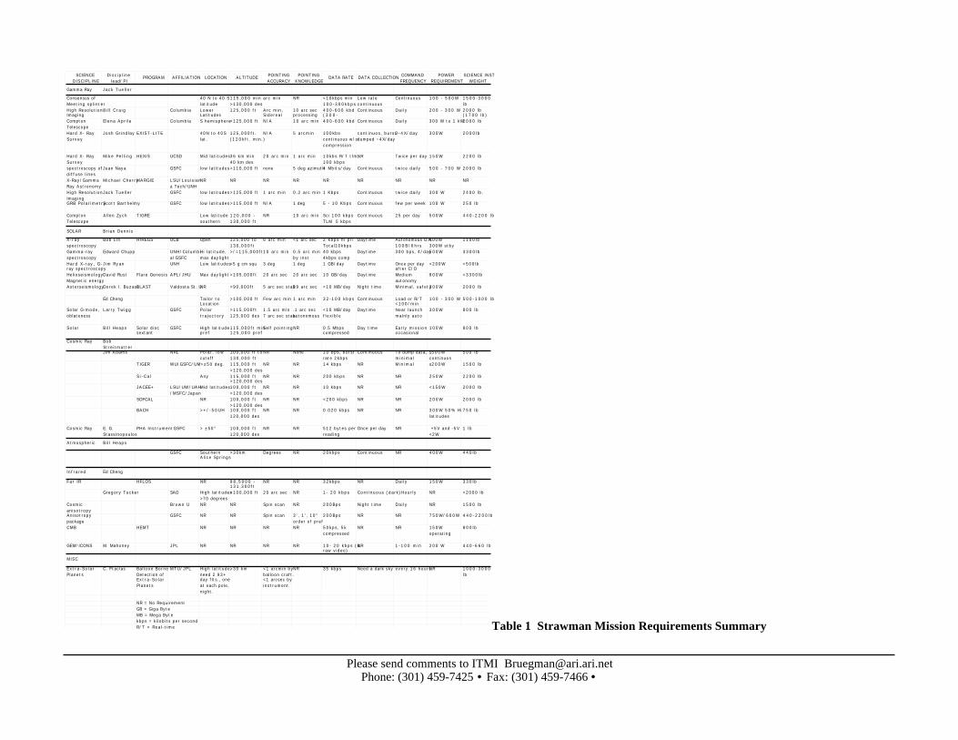
Figure 2 displays the range of altitude requirements by science discipline and indicates the percentage ofexperiments that would be satisfied by certain altitudes.
Figure 3 displays the range of science instrument weight requirements by science discipline and indicates thepercentage of experiments that would be satisfied by certain weight capabilities.
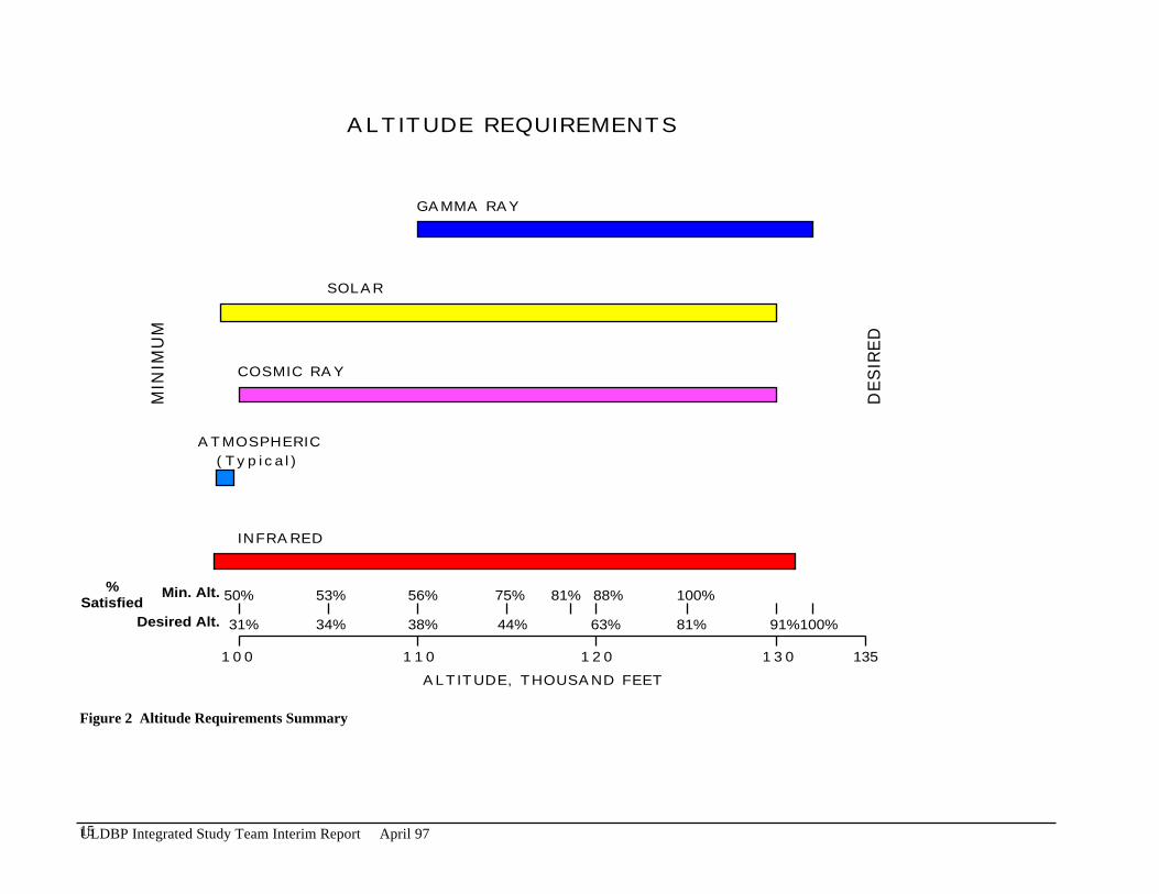
Figure 4 displays the range of science instrument power requirements by science discipline and indicates thepercentage of experiments that would be satisfied by a certain power in Watts.
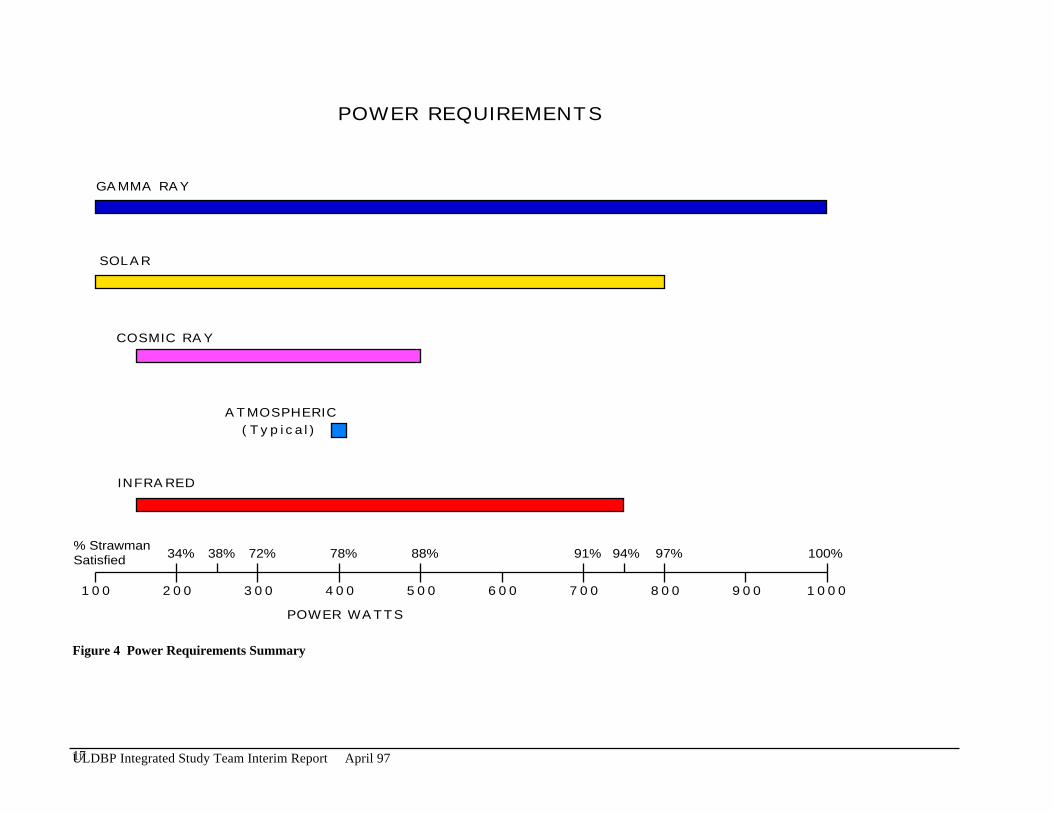
Figure 5 displays the range of science instrument pointing accuracy requirements by science discipline andindicates the percentage of experiments that would be satisfied by certain values in degrees, arcminutes, orarcseconds.
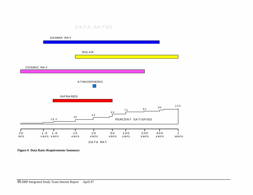
Figure 6 displays the range of science instrument data rate requirements by science discipline and indicates thepercentage of experiments that would be satisfied by a various data rates.
11ULDBP Integrated Study Team Interim Report April 97
SCIENCE DISCIPLINE
Discipline lead/PI
PROGRAM AFFILIATION LOCATION ALTITUDE POINTING ACCURACY
POINTING KNOWLEDGE
DATA RATE DATA COLLECTION COMMAND FREQUENCY
POWER REQUIREMENT
SCIENCE INST WEIGHT
Gamma Ray Jack Tueller
Consensus of Meeting splinter
40 N to 40 S latitude
115,000 min >130,000 des
arc min NR <10kbps min 100-300kbps
Low rate continuous
Continuous 100 - 500W 1500-3000 lb
High Resolution Imaging
Bill Craig Columbia Lower Latitudes
125,000 ft Arc min, Sidereal
10 arc sec processing
400-600 kbd (300-
Continuous Daily 200 - 300 W 2000 lb (1700 lb)
Compton Telescope
Elena Aprile Columbia S hemisphere>125,000 ft N/A 10 arc min 400-600 kbd Continuous Daily 300 W to 1 kW2000 lb
Hard X- Ray Survey
Josh Grindlay EXIST-LITE 40N to 40S lat.
125,000ft. (120kft. min.)
N/A 5 arcmin 100kbs continuous w/o compression
continuos, burst-dumped ~4X/day
2-4X/day 300W 2000lb
Hard X- Ray Survey
Mike Pelling HEXIS UCSD Mid latitudes36 km min 40 km des
20 arc min 1 arc min 10kbs R/T tlm, 100 kbps
NR Twice per day 150W 2200 lb
spectroscopy of diffuse lines
Juan Naya GSFC low latitudes>110,000 ft none 5 deg azimuth4 Mbits/day Continuous twice daily 500 - 700 W 2000 lb
X-Ray/Gamma Ray Astronomy
Michael CherryMARGIE LSU/Louisiana Tech/UNH
NR NR NR NR NR NR NR NR NR
High Resolution Imaging
Jack Tueller GSFC low latitudes>125,000 ft 1 arc min 0.2 arc min 1 Kbps Continuous twice daily 300 W 2400 lb.
GRB PolarimetryScott Barthelmy GSFC low latitudes>115,000 ft N/A 1 deg 5 - 10 Kbps Continuous few per week 100 W 250 lb
Compton Telescope
Allen Zych TIGRE Low latitude southern
120,000 - 130,000 ft
NR 10 arc min Sci 100 kbps TLM 5 kbps
Continuous 25 per day 500W 440-2200 lb
SOLAR Brian Dennis
X-ray spectroscopy
Bob Lin HIREGS UCB Open 125,000 to 130,000ft
6 arc min <1 arc sec 2 kbps hi pri Total10kbps
Daytime Autonomous O.K. 100B/6hrs
400W 300W stby
1100lb
Gamma-ray spectroscopy
Edward Chupp UNH/Columbia/GSFC
Hi latitude, max daylight
>/=115,000ft 10 arc min 0.5 arc min by inst
40 kbps 4kbps comp
Daytime 300 bps, 4/day500W 3300lb
Hard X-ray, G-ray spectroscopy
Jim Ryan UNH Low latitudes<5 g cm squ 3 deg 1 deg 1 GB/day Daytime Once per day after C/O
<200W <500lb
Helioseismology Magnetic energy
David Rust Flare Genesis APL/JHU Max daylight>105,000ft 20 arc sec 20 arc sec 10 GB/day Daytime Medium autonomy
800W <3300lb
Asterseismology Derek l. BuzasiBLAST Valdosta St. UNR >90,000ft 5 arc sec stab39 arc sec <10 MB/day Night time Minimal, safety300W 2000 lb
Ed Cheng Tailor to Location
>100,000 ft Few arc min 1 arc min 32-100 kbps Continuous Load or R/T <100/min
100 - 300 W 500-1000 lb
Solar G-mode, oblateness
Larry Twigg GSFC Polar trajectory
>115,000ft 125,000 des
1.5 arc min 7 arc sec stab
.1 arc sec autonomous
<10 MB/day flexible
Daytime Near launch mainly auto
300W 800 lb
Solar Bill Heaps Solar disc sextant
GSFC High latitude pref
115,000ft min 125,000 pref
Self pointingNR 0.5 Mbps compressed
Day time Early mission occasional
100W 800 lb
Cosmic Ray Bob StreitmatterJim Adams NRL Polar, low
cutoff100,000 ft to 130,000 ft
NR None 10 bps, burst rate 2kbps
Continuous To dump data, minimal
≤500W continuos
500 lb
TIGER WU/GSFC/UM>±50 deg. 115,000 ft >120,000 des
NR NR 14 kbps NR Minimal ≤200W 1500 lb
Si-Cal Any 115,000 ft >120,000 des
NR NR 200 kbps NR NR 250W 2200 lb
JACEE+ LSU/UW/UAH/MSFC/Japan
Mid latitudes100,000 ft >120,000 des
NR NR 10 kbps NR NR <150W 2000 lb
SOFCAL NR 100,000 ft >120,000 des
NR NR <200 kbps NR NR 200W 2000 lb
BACH >+/-50UH 100,000 ft 120,000 des
NR NR 0.020 kbps NR NR 300W 50% Hi latitudes
750 lb
Cosmic Ray E. G. Stassinopoulos
PHA InstrumentGSFC > ±50° 100,000 ft 120,000 des
NR NR 512 bytes per reading
Once per day NR +5V and -5V <2W
1 lb
Atmospheric Bill Heaps
GSFC Southern Alice Springs
>30km Degrees NR 20kbps Continuous NR 400W 440lb
Infrared Ed Cheng
Far IR HFLOS NR 98,5000 - 131,300ft
NR NR 32kbps NR Daily 150W 330lb
Gregory Tucker SAO High latitudes >70 degrees
>100,000 ft 20 arc sec NR 1- 20 kbps Continuous (dark)Hourly NR <2000 lb
Cosmic anisotropy
Brown U NR NR Spin scan NR 200Bps Night time Daily NR 1500 lb
Anisotropy package
GSFC NR NR Spin scan 3', 1', 10" order of pref
200Bps NR NR 750W/600W 440-2200lb
CMB HEMT NR NR NR NR 50kps, 5k compressed
NR NR 150W operating
800lb
GEM/ICONS M. Mahoney JPL NR NR NR NR 10- 20 kbps (& raw video)
NR 1-100 min 200 W 440-660 lb
MISC
Extra-Solar Planets
C. Ftaclas Balloon Borne Detection of Extra-Solar Planets
MTU/JPL High latitude, need 2 93+ day flts., one at each pole, night.
>30 km <1 arcmin by balloon craft. <1 arcsec by instrument
NR 35 kbps Need a dark sky every 16 hoursNR 1000-3000 lb
NR = No RequirementGB = Giga ByteMB = Mega Bytekbps = kilobits per secondR/T = Real-time Table 1 Strawman Mission Requirements Summary
Please send comments to ITMI [email protected]: (301) 459-7425 • Fax: (301) 459-7466 •

SCIENCE DISCIPLINE
Discipline lead/PI
PROGRAMTHERMAL
REQUIREMENTTIME PER
OBSERVATIONRESPONSE
TIMESCIENCE DATA
DELAYDATA DURING COMMAND
EXPENDABLE REQUIREMENTS
PI OPERATION OR SUPPORT GRP
Recovery Focal Length
Gamma Ray Jack TuellerConsensus of Meeting splinter
Instrument cooling
Duty cycle min 50%, 100% des
R/T Intermittent acceptable
Continuous Cryogens NR NR
High Resolution Imaging
Bill Craig Normal BalloonHours Some R/T Daily Desirable None PI NR
Compton Telescope
Elena Aprile Normal BalloonHours NR Daily Not required Possibly Cryogens
PI NR
Hard X- Ray Survey
Josh Grindlay EXIST-LITE normal balloon; 0-20 deg C
continuous survey
R/T desired real-time desired, 1 day minimum
not req. None PI desired
Hard X- Ray Survey
Mike Pelling HEXIS Inst 0-20 deg C elec 0-40 deg C
NR NR R/T to hours Yes NR NR NR
spectroscopy of diffuse lines
Juan Naya cryogenic 100 days NR weekly not required maybe cryogenPI NR
X-Ray/Gamma Ray Astronomy
Michael CherryMARGIE NR NR NR NR NR NR NR NR
High Resolution Imaging
Jack Tueller normal 10 mins - 10 hours
NR weekly some R/T
not required none PI NR 8 meters
GRB PolarimetryScott Barthelmy inst -10 to 44 deg C
continuous need R/T for 500 bits
weekly some R/T
not required none PI NR
Compton Telescope
Allen Zych TIGRE 0-30 deg C NR NR 5 kbps R/T Sci EOM
Cal prior to mode change
NR PI Recover data min
SOLAR Brian DennisX-ray spectroscopy
Bob Lin HIREGS Det 0-20deg C Elec 0-40deg C
NR NR Recovery of data bank
NR NR PI pref Highly Desirable
Gamma-ray spectroscopy
Edward Chupp NR One flare above 20 MeV, min
NR Recovery of data bank
NR Liquid nitrogenPI Highly Desirable
Hard X-ray, G-ray spectroscopy
Jim Ryan 0 to 20 deg C One flare min NR NR NR NR PI Recovery of data
Helioseismology Magnetic energy
David Rust Flare GenesisBalloon qualifiedNR NR Recovery of data
NR NR PI pref Critical
Asterseismology Derek l. BuzasiBLAST Stability of optical system
NR NR NR NR NR NR Recovery of data pref
Ed Cheng Heater Control Hours Some R/T Weekly, some R/T
Most Likely NotCryogens PI NR
Solar G-mode, oblateness
Larry Twigg Good history NR NR 20 days NR NR Pref strong PI NR
Solar Bill Heaps Solar disc sextant
Pref continuous sun viewing
Continuous in day light
NR EOM Cal prior to mode change
NR PI Recover data min
Cosmic Ray Bob StreitmatterJim Adams -30° C to
+ 50 ° CNR NR Any delay is
okayNR NR PI to save
replacement cost
TIGER 0≤T≤30° C NR NR NR NR NR NR NRSi-Cal NR NR NR NR NR NR NR NRJACEE+ NR NR NR NR NR NR NR WaterproofSOFCAL NR NR NR NR NR NR NR NRBACH NR NR NR NR NR NR NR NR
Cosmic Ray E. G. Stassinopoulos
PHA Instrument
NR Continuous NR NR NR NR NR Desired, not required
Atmospheric Bill HeapsNR Continuous NR NR NR NR NR NR
Infrared Ed ChengFar IR HFLOS NR NR NR Daily NR NR NR NR
Gregory Tucker Instrument cooling
20 minutes R/T R/T to 15 min delay
Required Liquid helium support group NR
Cosmic anisotropy 4 deg K cold plateNight time NR Continuous NR Liquid Helium NR NR
Anisotropy package
NR NR NR Continuous NR NR NR Highly desired
CMB HEMT NR NR NR Continuous NR Liquid Helium NR NRGEM/ICONS M. Mahoney Instrument
coolingNR R/T R/T Required Cryogens Open NR
MISCExtra-Solar Planets
C. Ftaclas Balloon Borne Detection of Extra-Solar Planets
NR 30 min R/T every 16 hours for acquisition of target (star)
Storage okay for later transmission
Required for acquisition, could compress for cellular.
Maybe, detector needs to be cooled.
PI Desired, telescope expensive
6 m long telescope, off axis design. 1.5 m aperture.Table 2 Strawman Mission Requirements Summary (continued)
13ULDBP Integrated Study Team Interim Report April 97

100 Day Balloon Workshop - Envisioned Communication RequirementsDiscipline Proposal PI Program
AcronymData Rate(kbits/sec)
Daily DataVolume(Mbits)
Mission DataVolume(Gbits)
Command Contactsper day
Gamma Ray High Resolution Imaging Bill Craig 0.60 0.06 1Gamma Ray Compton Telescope Elena Aprile 0.60 0.06 1Gamma Ray Hard X-Ray Survey Josh Grindlay EXIST-
LITE100 8640.00 864.00 4
Gamma Ray Hard X-Ray Survey Mike Pelling HEXIS 100 8640.00 864.00 1Gamma Ray Spectroscopy of Diffuse Lines Juan Naya 4.00 0.40 2Gamma Ray High Resolution Imaging Jack Tueller 1 86.40 8.64 2Gamma Ray GRB Polarimetry Scott Barthelmy 10 864.00 86.40 1Gamma Ray Compton Telescope Allen Zych TIGRE 100 8640.00 864.00 25Solar X-Ray Spectroscopy Bob Lin HIREGS 10 864.00 86.40 0.1Solar Gamma-Ray Spectroscopy Edward Chupp 40 3456.00 345.60 4Solar X/G-Ray Spectroscopy Jim Ryan 8000.00 800.00 1Solar "Helioseismology, Mag.
Energy"David Rust 80000.00 8000.00 0.1
Solar Asterseismology Derek 1. Buzasi 80.00 8.00 0.1Solar Ed Cheng 100 8640.00 864.00 ?Solar "Solar G-Mode, Oblateness" Larry Twigg 80.00 8.00 0.1Solar Solar Bill Heaps 500 43200.00 4320.00 0.1Cosmic Ray Jim Adams 2 172.80 17.28 0.1Cosmic Ray TIGER 14 1209.60 120.96 0.1Cosmic Ray Si-Cal 200 17280.00 1728.00Cosmic Ray JACEE+ 10 864.00 86.40Cosmic Ray SOFCAL 200 17280.00 1728.00Cosmic Ray BACH 0.02 1.73 0.17Atmospheric Bill Heaps (?) 20 1728.00 172.80Infrared Far IR HFLOS 32 2764.80 276.48 1Infrared Gregory Tucker 20 1728.00 172.80 24Infrared Cosmic Anisotropy 0.2 17.28 1.73 1Infrared Anisotropy package 0.2 17.28 1.73Infrared CMB HEMT 50 4320.00 432.00Infrared GEM/ICONS (raw video!) M. Mahoney 20 1728.00 172.80 100Extra-Solar Planets Balloon Borne Detection of
Extra-Solar PlanetsC. Ftaclas 35 3024.00 302.40 1.5
Table 3 Communications Requirements Summary
Please send comments to ITMI [email protected]: (301) 459-7425 • Fax: (301) 459-7466 •
100 110 120 130
SOLAR
GAMMA RAY
COSMIC RAY
ATMOSPHERIC(Typical)
INFRARED
ALTITUDE REQUIREMENTS
ALTITUDE, THOUSAND FEET
MIN
IMUM
DESIR
ED
135
100%91%81%63%44%38%34%31%
100%88%81%75%56%53%50% %Satisfied
Min. Alt.
Desired Alt.
Figure 2 Altitude Requirements Summary
15ULDBP Integrated Study Team Interim Report April 97

0 500 1000 1500 2000 2500 3000 3500
SOLAR
GAMMA RAY
COSMIC RAY
ATMOSPHERIC(Typical)
INFRARED
WEIGHT REQUIREMENTS
WEIGHT POUNDS
% StrawmanSatisfied
100%38% 47% 75% 88% 91% 94%
Figure 3 Weight Requirements Summary
16ULDBP Integrated Study Team Interim Report April 97
100 200 300 400 500 600 700 800
POWER WATTS
SOLAR
GAMMA RAY
COSMIC RAY
ATMOSPHERIC(Typical)
INFRARED
POWER REQUIREMENTS
900 1000
34% 38% 72% 78% 88% 91% 94% 97% 100%% StrawmanSatisfied
Figure 4 Power Requirements Summary
17ULDBP Integrated Study Team Interim Report April 97
SOLAR
GAMMA RAY
COSMIC RAYNO REQUIREMENT
ATMOSPHERIC
INFRARED (ORDER OF PREFERENCE)
POINTING ACCURACY
POINTING ACCURACY
1DEG
0.1ARC SEC
1ARC SEC
3DEG
1.5ARC SEC
10ARC SEC
1ARC MIN
3ARC MIN
ACCURACY
KNOWLEDGE
LEGEND
20ARC MIN
NO REQUIREMENT
48
10090
7986
6959
62
4555
PERCENTAGE SATISFIEDKNOWLEDGE
ACCURACY
Figure 5 Pointing Requirements Summary
18ULDBP Integrated Study Team Interim Report April 97
1.0KBPS
10KBPS
20KBPS
50KBPS
400KBPS
SOLAR
GAMMA RAY
COSMIC RAY
ATMOSPHERIC
INFRARED
DATA RATES
DATA RATE
1MBPS
200KBPS
20BPS
1.6KBPS
18.530
4463
74 8190
100
PERCENT SATISFIED
100KBPS
Figure 6 Data Rates Requirements Summary
19ULDBP Integrated Study Team Interim Report April 97
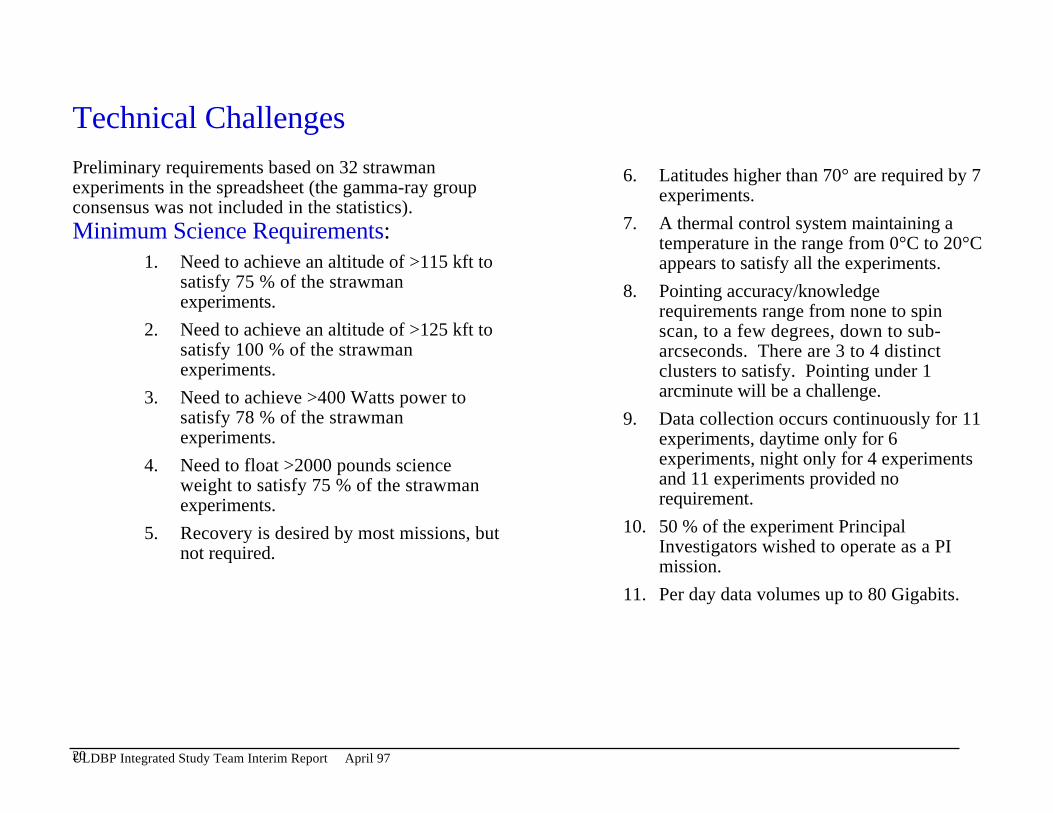
Technical Challenges
Preliminary requirements based on 32 strawmanexperiments in the spreadsheet (the gamma-ray groupconsensus was not included in the statistics).
6. Latitudes higher than 70° are required by 7experiments.
7. A thermal control system maintaining atemperature in the range from 0°C to 20°Cappears to satisfy all the experiments.
Minimum Science Requirements:1. Need to achieve an altitude of >115 kft to
satisfy 75 % of the strawmanexperiments.
8. Pointing accuracy/knowledgerequirements range from none to spinscan, to a few degrees, down to sub-arcseconds. There are 3 to 4 distinctclusters to satisfy. Pointing under 1arcminute will be a challenge.
2. Need to achieve an altitude of >125 kft tosatisfy 100 % of the strawmanexperiments.
3. Need to achieve >400 Watts power tosatisfy 78 % of the strawmanexperiments.
9. Data collection occurs continuously for 11experiments, daytime only for 6experiments, night only for 4 experimentsand 11 experiments provided norequirement.
4. Need to float >2000 pounds scienceweight to satisfy 75 % of the strawmanexperiments.
10. 50 % of the experiment PrincipalInvestigators wished to operate as a PImission.
5. Recovery is desired by most missions, butnot required.
11. Per day data volumes up to 80 Gigabits.
20ULDBP Integrated Study Team Interim Report April 97
Design Options Needed Based On Science Requirements (Mission operations profiles or concepts based on the strawman science payload requirements from theOctober 96 workshop)
There are two concepts with different requirements based on latitude.
1. Inside The Arctic Or Antarctic Circles• Night time operations require nonsolar power source
• Reliable communications for polar zones of exclusion♦ Geostationary communications satellites can not see poles♦ Many of the LEO, Little LEO & MEO communications ventures tend to have
∗ 60° inclined orbits, again excluding the poles
♦ & Need to find those with coverage at the poles. There are at least 3 known candidates --∗ IRIDIUM, low data rate∗ GLOBALSTAR, 19 kbps∗ ICONET, rates unknown
♦ & Need to investigate Military Communication Satellites ( U.S., Russian, etc.)
♦ & Need to investigate amateur radio operators communication satellites.
•
& Areas requiring further study. For details see section on list of identified technologies for further evaluation.
21ULDBP Integrated Study Team Interim Report April 97
100 day missions will experience extreme day/night cycles♦ need to design for 60 day long days and nights
∗ 4 experiments want day time observations⇒ this limits mission to ≤ 60 days
∗ 2 experiments want continuous dark⇒ this allows 100 day mission with substantial power needs
∗ 1 experiment wants continuous observations⇒ this allows 100 day mission (30 to 60 days sun then 40 to 70 days dark)
♦ this impacts the power design and♦ the thermal design
• equipment needs to survive radiation at magnetic poles
• risk of cutbacks in NSF program (cost would become great)
2. Low Latitude
• & Need to investigate power systems sufficient for the science instrument and the support system♦ a sun tracking solar array or an omni directional array♦ battery or other storage for 12 hours♦ non-traditional power source, e.g., wind/electrical generator a few 1000 feet below balloon
• requires thermal control for 12 hour day/night cycle
• may require pointing control for communications antenna
• may require new international agreements
• inadvertent technology transfer considerations
& Areas requiring further study. For details see section on list of identified technologies for further evaluation.
22ULDBP Integrated Study Team Interim Report April 97
Design concepts common to both latitude options described above are as follows.
1. The payload will be "tracked" continuously from a central ground station.
2. Trajectory forecasts will be maintained and continuously updated.• forecasts will include wind predictions.
3. Real-time data and commanding will be available at the launch site, central ground station, and PI institution.• Need to design for a line of sight in flight checkout period after launch (~ 5-6 hours duration)• 50% of PIs want PI mode of operation.
4. Science data will be recovered at a frequency that insures mission success and no more than 25% of accumulateddata is lost.
5. Science instrument pointing requirements show need for four different systems. Appropriate modular design andinterface needed.
• No pointing required
• Spin scan system required
• Pointing to one arcmin required
• Pointing to arcsec and sub-arcsec required
23ULDBP Integrated Study Team Interim Report April 97
Current Balloon Program Capabilities
• Power - The SIP provides 300 Watts, as an upper limit 600 Watts has been supported.
• Commanding & Data Return - Omni/TDRS supports 2 kbps, up to 6 kbps maximum supported.
• Thermal design - The thermal environment is much more severe than the typical spacecraft environmentwhen looking at the cyclic thermal loads. The thermal analysis techniques and control methods employed forballooning are fairly well established and have been proven on many flights. Most of the control methods arepassive and do not require thermal blankets or complicated active systems. The tools currently used areTRASYS, SINDA, and TSS. Due to the long days and nights a totally passive system may not be possible. Therequired power allocation for thermal control may be higher than for a typical spacecraft which is around 5%.
• Automated operations - These include 1) an aneroid flight termination switch in the event a balloondescends below a minimum acceptable altitude for flight safety; 2) a burst detector which will terminate the flightin the event of a balloon structural failure; 3) an automated balloon differential pressure control/valve system forpressurized balloon systems; and 4) an automated ballast control system for the dropping of ballast formaintenance of altitude.
• Location of Balloon Craft - Balloon/ballooncraft position is determined on-board by redundant GPSreceivers with the information transmitted to the ground station through the FM/PCM line of sight link, theINMARSAT Standard C over-the-horizon (OTH) link, the HF/ARGOS OTH link, or the TDRSS MA or SA link.In addition, position is also obtained vis ARGOS PTT's (Platform Transmitter Terminal) received at the WallopsRemote Operations Control Center or the Palestine Operations Control Center.
24ULDBP Integrated Study Team Interim Report April 97
Areas Requiring Further Technical DefinitionThe information received from the science community has some requirements that appear technically challenging. Thissection attempts to describe some of the areas that require more technical definition.
Weight: Some of the strawman missions have requirements of up to 3300 lbs., many require 2000 lbs. For thedemonstration mission only a 2000 lbs hang weight is advertised. This is a challenge for the ULDB program.
The system weight must be viewed from a system standpoint. There are many areas where the structural system canbe "designed" instead of "built" for significant weight savings. This requires a weight analysis for each mission.
Power: Some of the strawman missions require over 800 Watts of power. The challenge is to meet higher power needswith manageable impact to weight and stability. An engineering trade study is needed to identify which power sourcemight best meet the needs of the ULDB program. Some potential candidates for power sources are provided in theSummary List Of Technologies Under Consideration section beginning on page 40.
A combination of the different types of power systems may be the solution.
Location: Redundant GPS will provide location information. ARGOS is currently used as a backup position source.
Pointing Control: Several of the strawman missions require pointing control and knowledge. The challenge will be toachieve the desired accuracy in a craft acting like a pendulum with some elasticity in the load train. Also, for thosemissions requiring a lot of power the size of the solar arrays could introduce jitter into the system.
Candidate pointing systems for study are provided in the Summary List Of Technologies Under Consideration sectionbeginning on page 40.
25ULDBP Integrated Study Team Interim Report April 97
Terminate and Recovery Systems
Payload recovery is not a requirement.• It is desired by the majority of PIs.• High data rate line-of-sight telemetry and preemptive cut down plans for recovery and re-flight in case of
payload failure may be feasible for some missions.A study on feasibility and systems needed should be performed.
• An alternative concept could be developed for payloads that require recovery with defined tradeoffs.• An aircraft could be made available at potential termination areas for cut down and recovery operations.• Recovery systems (parachute) could be deployed on flights.• Is a self-destruct system needed?• Other terminate and recovery options for evaluation are:
♦ steerable parachute systems to improve recovery operations,♦ ground transmitter to ease finding a lost payload,
⇒ look at animal collar systems,⇒ emergency transmitter systems,
♦ inflatable flotation devices,♦ "smart" auto cut down systems that use GPS + wind predictions, and♦ improved wind prediction.
Autonomous Operations: This is desired on many of the strawman missions and will likely be needed on mostmissions to handle functions like thermal stability, battery discharge and charge cycles, other day/night cycle activities,and to execute safety procedures under various scenarios such as failure of balloon location communications with theoperations team. These systems need to be designed and tested to provide high probability of survival for 100 days ataltitude.
26ULDBP Integrated Study Team Interim Report April 97
Thermal: Thermal control needs to be maintained to within the required operations temperature range for both thescience instrument and the support package. The tools currently use for thermal analysis are TRASYS, SINDA, andTSS. They are proven for the existing balloon programs; they have yet to be proven for the ULDB Program. Thefollowing tasks need to be undertaken to provide models to help evaluate different ideas for maintaining thermal controlof the balloon craft packages.
1) Characterize the range of wind speeds likely to be encountered by a balloon payload at float. An initial estimatecan be obtained from existing measurements of wind speed vs. altitude which NSBF takes with their routine soundings,by taking the derivative of this curve and multiplying by the length of the flight train.
2) Develop a model for wind cooling at float conditions. There is likely already such a model at least for pressure ~1atm; if not it is fairly clear how to develop the framework, since the airflow is likely to be nearly laminar. If necessary,develop a plan to validate this model for float conditions.
3) Develop a model for convective cooling, or establish design rules under which convection can be safely ignored.These are only models to help determine thermal design. Since a consistent, half degree increase or decrease in thetemperature could put the balloon craft into a non-operating state, a challenge will be to devise a test strategy that canensure high probability of thermal survival of the balloon craft for ≥100 days. Additional systems for cooling or heatingwill be needed for some of the experiments. An area of concern is that these additional systems will impact powerrequirements for the balloon.
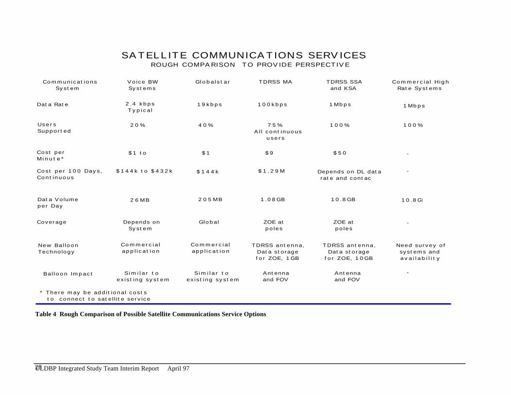
Communications: There appear to be low rate options that can accomodate both commanding and return of theballoon craft and science instrument engineering and housekeeping telemetry. Costs of various options needs to bestudied. Options for the return of high rate science data are limited and need further study. Some of the strawmanmissions require real time response. Some of the experiments call for daily data return, daily commanding or evenhourly commanding. This raises the question of what is an acceptable level of cost. TDRSS and Military satellitescannot be relied on to give balloons top priority, other options should be explored. Table 4 outlines initial information onsome of the communications options that need further study. Figure 7 provides a high level concept forcommunications requirements and packaging schemes.
27ULDBP Integrated Study Team Interim Report April 97
SATELLITE COMMUNICATIONS SERVICESROUGH COMPARISON TO PROVIDE PERSPECTIVE
Communications System
Voice BWSystems
Globalstar TDRSS MA TDRSS SSAand KSA
Commercial HighRate Systems
Data Rate 2.4 kbpsTypical
19kbps 100kbps 1Mbps 1Mbps
UsersSupported
20% 40% 75%All continuous
users
100% 100%
Cost per Minute*
$1 to 3 $1 $9 $50 -
Cost per 100 Days, Continuous
$144k to $432k $144k $1.29M Depends on DL data rate and contacts
-
Data Volumeper Day
26MB 205MB 1.08GB 10.8GB 10.8GB
Coverage Depends onSystem
Global ZOE atpoles
-ZOE atpoles
New Balloon Technology
Commercialapplication
Commercialapplication
TDRSS antenna,Data storagefor ZOE, 1GB
TDRSS antenna,Data storage
for ZOE, 10GB
Need survey ofsystems andavailability
Balloon Impact Similar toexisting system
Similar toexisting system
Antennaand FOV
Antennaand FOV
* There may be additional costs to connect to satellite service
-
Table 4 Rough Comparison of Possible Satellite Communications Service Options
28ULDBP Integrated Study Team Interim Report April 97

High RateTransmitter
DirectionalAntenna
Gimbal
Balloon Controller
On-BoardData Storage
Instrument
AttitudeSensor
Instrument Controller
Gimbal
EngData
IFFTransponder
OmniAntenna
Balloon-to-GroundCommunications
Transceiver
StorageData
Dumps
Monitor & ControlCommunications
Balloon-to-SatelliteCommunications
Transceiver
Downward-LookingAntenna
Upward-LookingAntenna
Monitor & ControlCommunications
Attach to bottom of balloon,Parachute to ground after ascent ?
Integrated Ballooncraft - Required Systems - Packaging Schemes
Rea
l tim
e or
sto
red
M&
C d
ata
Con
trol
Con
trol
Figure 7 High Level Communications Concept
29ULDBP Integrated Study Team Interim Report April 97
Continuous Coverage
Continuous coverage may not be possible, practically or due to cost. There are two ways to go: non-continuouscommunications, or meeting the PI’s requirements. It is not clear if much thought has been given to continuouscoverage issues such as personnel to monitor communications around the clock for 100 days or the cost to supportsuch operations.
Zones of Exclusion
An initial calculation of the zones of exclusion is presented in Figure 8. The ZOE is described for a 3 TDRSS system,expected in the future, not currently (2 TDRSS system). If the balloon drifts into these zones there needs to be analternate way to contact the balloon for safety reasons. These issues are under study.
A hybrid solution of a 2 kbps communications connection for command and housekeeping and a higher rate line for datareturn may be appropriate and will be studied.
30ULDBP Integrated Study Team Interim Report April 97
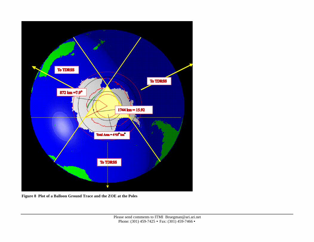
Figure 8 Plot of a Balloon Ground Trace and the ZOE at the Poles
Please send comments to ITMI [email protected]: (301) 459-7425 • Fax: (301) 459-7466 •
System Engineering Information and Concerns
How might the physical environment affect the balloon craft? This relates to passage to altitude and in retrieval as wellas operation at the limits of the atmosphere in the range of 100,000 ft to 130,000 ft. The balloons may fly mainly aroundthe poles or in equatorial areas. Conditions that may affect the balloons performance and integrity are of concern. Asummary of the known balloon environment follows.
Balloon Environment Summary
Balloon Behavior:Balloon Ascent Rate : typical 800-1000 fpm. It takes around three hours to attain altitude.Balloon Rotation Rates : typical < 60 deg/min at float
have seen during ascent/descent ~ 180 deg/minBalloon Dynamics : (Vertical Oscillations & Frequency Forthcoming)
Loads:Launch : typical < 1.5 g’sAscent : typical < 1.1 g’s due to wind shears, ballast drops, etc.Terminate : typical < 10 g’sImpact Velocity : typical < 20 fpsWind or wind shear effects TBD. This is particularly important for those experiments that require pointing accuracyand have large power demands.
Release acceleration - 10 g pulse when parasail opens.The termination loading can be around 10 g's. We have typical curves for the acceleration and velocity at terminationfor balloon payloads. The implementation of a flight termination load reduction technique is now being explored using arip stitch attenuator. This promises to reduce the 10 g loading by half or more. The technique used could also betailored to the specific payload to reduce the shock loading even more. The method and procedure to do this has beendetermined and it is a matter of implementation and testing.
Please send comments to ITMI [email protected]: (301) 459-7425 • Fax: (301) 459-7466 •
Landing acceleration (use airbags like the Mars lander)?This is a known quantity, and much less severe than the release accelerations. Crush pads are not as elegant as anairbag system, but can be easily designed to do the job for minimal weight, minimal complexity and minimal cost.
A related issue to all of the accelerations that a payload may see concerns what constitutes a fully recovered payload. Itis obviously not acceptable to have pieces fall off the payload at termination and then fall to the ground. Depending onthe parts, it may be acceptable for them to become non-functional at termination or upon ground impact. This is an areafor a trade study or cost benefit analysis. The core of the instrument which accounts for most of the cost of thepayload may be able to handle the imposed acceleration loads. The associated costs and increased weight to ensuresurvivability of the other parts may not be worth it. Some items could be considered as "throw away" if the effort toensure survivability costs more than replacement/refurbishment.
This should all be put in the context that the main acceleration event is after the operating portion of its life. This isexactly opposite of a launched spacecraft which sees its worst accelerations at launch before being put into operation.One could envision, for example, a detector system that is built to handle the launch acceleration, but not the terminationevent. To build the same detector that can survive the termination would be a significantly heavier and more expensive.
Atmospheric :Tropics : -90C @ ~ 50-60 k-ft altitudePolar : -45C @ ~ 30-35 k-ft altitudemid-latitude : -55C @ ~45-60 k-ft --> -80C in summer(seasonal & latitudinal fluctuations)Temperature profile - Troposphere can reach -90°C and balloon can take 20 to 30 minutes to travel through thetroposphere during launch. Launch temperature range can be from -10˚C to +40˚C
Chemical components and vapor levels TBD.
33ULDBP Integrated Study Team Interim Report April 97
Radiation:Solar Constant (seasonal) : 1358 W/m2 (nominal)
1312 W/m2 (minimum)1404 W/m2 (maximum)
Albedo : 0.1 (minimum)0.9 (maximum) polar
Earth Flux: 90.7 W/m2 (minimum, Tropospheric cloud top temperatures of -90°C)594. W/m2 (maximum, Desert @ 320K planet temperature)
Electro-static gradients, Electro-magnetic fields TBD.
Lightning Strike:A concern at high altitudes is lightning strikes at float altitude coming up from clouds below (which has happenedcatastrophically on one mission) when flying across severe storm boundaries and the type of payload. Special hardeningof instrumentation or procedures may need to be developed.
34ULDBP Integrated Study Team Interim Report April 97
Programmatic System Engineering Concerns
In studying the Balloon craft subsystems the Balloon Program needs to be tied into NASA objectives. We need toidentify NASA needs that correspond to the Balloon Program needs. Examples are given below.
Data Collection - Which methods is more useful to future NASA missions? Satellite cellular command/TDRS telemetrylink hybrid would be of interest to some small missions, what are other options?
Thermal - What new thermal control systems being designed for use in space might have application on balloons?
Power - Are there new solar cells, storage batteries, or fuel cells not yet tested that could be used on a balloon craft toprovide test data useful for future space missions.
Pointing Control and Autonomous Operations - Can the balloon program perform pathfinder flights that test newtechnology that could be used on small satellites or proposed balloon exploration of other planets?
Risk Mitigation - Can any of the new technologies identified be flown on current LDB programs to reduce to the 100day programs?
35ULDBP Integrated Study Team Interim Report April 97

Differences between balloon and space mission or ground experiment
• Launch♦ Large static charges can be generated during balloon inflation♦ Minimal vibration♦ Three hours needed to attain altitude♦ Restrictions based on launch vehicle
• In Flight Check of Balloon craft• Operation
♦ Long day/night cycles♦ Long periods in the ZOE
• The Environment♦ Different radiation environment♦ Residual atmosphere
36ULDBP Integrated Study Team Interim Report April 97
Other Issues Beyond The Scope Of This Study But Impacting The Program
• State Department Concerns on Technical Transfer.
• Risk Of Cutbacks In NSF Program (Cost Would Become Great).• Adequacy of Launch support services.
♦ Does the launch site need upgrading?• General International Agreements.• International involvement in development.
37ULDBP Integrated Study Team Interim Report April 97
Summary List Of Technologies Under Consideration(This is a partial list given that all study team members are not yet onboard.)(This will be a summary list of items identified in the report, it is not yet complete.)
Communications
Use of various communications satellite options.• TDRSS• Commercial (Little LEO, LEO, MEO, Geosync.)• Military (USA, Russian)• Amateur Radio Operator Satellites
Use of new Antenna Technologies.
Also various options on storage media drops over recoverable site.• Ruggedized Mass Data Storage Device
We are seeking a very low cost, compact, rugged mass data storage system with >1 terabit capacity. We areseeking a reusable system in the <$100K range. Several of these systems will be used for on-board recordingin the Advanced Long Duration Ballooning Program. Data will be recovered by parachuting to the ground(must withstand 10 g shocks). The drop package could be the whole system or just storage components.Multiple drops are required for reliable recovery of the data. The system needs to be able to operate ataltitudes between 100000 and 130000 feet (pressures between 11 and 3 millibar). It needs to operate from a 28V unregulated battery input. The operating temperature range without thermal control may be extreme so thatextended operating temperature range is desirable.
38ULDBP Integrated Study Team Interim Report April 97

Balloon Craft Location
• GPS• Weather Based Predictions
Power Systems
Some potential candidates for power sources are:
• Solar Arrays♦ The system must be designed, weight and size, for the worst case operating conditions for each, the polar
flights and the low latitude flights. The size of the system is not as much a concern as the size of the stowedsystem for launch. Deployable arrays, which can be either unrolled or inflated, may be a very desirable option.A sterling engine may also be an approach for using solar energy.
• New battery technology (rechargeable Lithium batteries?)♦ we want deep discharge but only 100 cycles + some TBD margin.♦ A fuel cell system can be attractive for high power "short" flights (1 kW, 20 days) or for moderate power for
longer flights (200 W, 100 days). Fuel cells also offer the advantages of "waste heat" for thermal control,water drops for ballasting, and the possibility of using the waste water for thermal storage (solar heated duringthe day and acting as a supplemental heat at night).
• Flywheel energy storage systems• Wind power generators suspended a few hundred or thousand feet below the balloon craft.
39ULDBP Integrated Study Team Interim Report April 97
Thermal Systems
• Thermal Blankets that will work at balloon flight altitudes.• High Efficiency Heat Pump System
We are seeking a high efficiency active thermal control system for a long duration balloon experiment. Totalthermal loads will be in the 300 to 1600 W range. Altitude of operation will be 100 to 130 kft (residualpressure between 11 and 3 millibars). The output thermal load must be radiated to the Earth or to space underall possible conditions (clouds, over water, over land, etc.) We require thermal control on the input side to +/-10 degrees C with a goal of +/- 1 degree C. Thermal control must be maintained in daytime and nighttimeconditions (12 hours daylight and 12 hours darkness at low latitudes). Expected mission lifetime is ~100 daysand we require a mean time to failure >200 days.
Pointing and Control Systems
Candidates for study involving the pointing system are as follows:
• Improved sensors are the primary requirement for better pointing♦ Fiber optic gyros♦ Phase comparison GPS orientation measurement♦ Daytime star cameras (special cooling and baffles required)
• Drive mechanical systems♦ Improved decoupler - three axis floating ball suspension torque sensing decoupler.♦ Load train improvements
∗ Better mechanical model∗ Increase stiffness∗ Non-magnetic and lighter using composites
♦ Magnetic torque’s or cold gas jets♦ Active damping for pendulum motion♦ Composite structure for less multipathing error in GPS and less magnetometer error♦ Active balancing systems
Superpressure Balloon Materials and Technology
40ULDBP Integrated Study Team Interim Report April 97

Code 741 response
This represents sub-SMEX space mission technologies that are applicable to and interested in the ULDB.
Economical Approach• A modular payload buss based on a commercial (industrial) PCA Pentium processor with a 1553 buss and R-442 I/O
(Spartan type design).• 1553 based GPS, sensor, and motor controls are available.
Power requirements especially with respect to the flight paths reveals a wide range of power options.• At the low end a solar array rechargeable lead gel-cell will produce the power required at the lowest cost with a
weight penalty.• A more weight efficient and costlier approach would be a lithium primary system or a solar array silver-cell
secondary system with individual cell charge control.
41ULDBP Integrated Study Team Interim Report April 97
Next Steps
• Mission Operations Concept Document
• Identify Different Design And Technology Options• Communications Options• Power And Thermal Options
• Develop Cost Estimates For These Options
42ULDBP Integrated Study Team Interim Report April 97