ultracon-service llc_product catalog
TRANSCRIPT

www.ndt.com.ua
Ukraine, 04071 Kiev, 8 Naberezhno�Lugova Str.
tel./fax: +38 044 531 37 27 (26)
PROMPRYLAD LLC ULTRACON�SERVICE LLC UkrSRINDT
® ®
®NON�DESTRUCTIVET E S T I N G
OKO
ASSOCIATION
DEAR SIRS!
OKO Association motto: "Turnkey NDT technologies".
We are trying to solve all the problems, connected with non�destructivetesting (NDT). Included to "OKO" Association enterprises have a full rangeof means for designing, manufacturing, warranty and post�warrantyservices of different equipment and NDT means, development of tech�niques and technologies of NDT procedure, training and certification ofNDT personnel.
For objects detection we have covered practically all the sphere of NDTmethods: ultrasonic, eddy current, visual, penetrant, magnetic particleand acoustic emission. Moreover by the Customer`s request we also pro�vide technical check�up, technical diagnostics (expert evaluation), thick�ness gauging of base metal and welded joints of equipment.
We can help you, if you decided to carry out non�destructive testing inyour own laboratory.
NDT technologies division of Ukrainian Scientific Research Institute forNon�Destructive Testing (UkrSRINDT) is the developer of more than 50NDT techniques for different items. Up�to�date NDT technologies areused when designing new techniques. The department is equipped withall the necessary equipment for implementation of different testingmethods such as ultrasonic, eddy current, acoustic emission, magneticparticle, visual and penetrant. One method or a group of methods is sep�arately chosen for optimum solution to problem. Integrated approach isused for each specific testing task.
We use high�level equipment for NDT techniques implementation."OKO" Association includes the leaders of domestic engineering in thefield of non�destructive testing such as Ultracon�Service LLC andPromprylad LLC. Ultrasonic, eddy current and magnetic particle flawdetectors, hardness testers, thickness gauges, wide range of ultrasonicand eddy current probes and other equipment have worked up Ukrainianmarket long ago due to its high quality and moderate prices.
Also, UkrSRINDT successfully designs high�efficiently Systems of auto�mated NDT at customer's request. It is both important and useful to showto the customer that if the solution of an assigned testing task was not
НДІ
found with serial equipment, than it is possible to design special�purposeprobes and make additions to the instrument software. Manufacturingcompanies to all delivered equipment hold consultations on its implementa�tion at a customer`s enterprise and carry out starting�up and commission�ing of NDT systems.
But unfortunately, it's impossible to produce everything. If it's difficult tosolve the testing task using instruments, produced by our companies, "OKO"Association can supply the necessary equipment, made by other producers.Among such equipment are X�ray units, consumables for magnetic particleand penetrant testing.
Service center of Promprylad LLC provides warranty and post�warrantyservices for all supplied equipment.
It is well known, that without skilful specialists any, even perfect�madeequipment, is just "piece of iron". NDT Training Center of Ultracon�ServiceLLC, NDT Certification Center of Promprylad LLC and PersonnelCertification Center of UkrSRINDT (Accreditation certificate of NationalAccreditation Agency of Ukraine NAAU No.6O012 dated 14.01.2014) willtrain NDT specialists of your enterprise and then issue them a certificate inconformity with the acting Regulatory Documentation. We are deeply con�vinced that only the authors of NDT procedures and designers of NDTinstruments can provide proper training for carrying out the testing.
We got all research engineers, methodologists, designers, producers ofinstruments, lecturers and experts together "under one roof". As a resultoptimal solution of any testing task can be found for the customer!
OKO Association � technology must be "Turnkey". It is the main principleof our work.
PROMPRYLAD LLC
ULTRACON�SERVICE LLC
Ukrainian scientific research institutefor non�destructive testing
OKO ASSOCIATION
TABLE OF CONTENTS
НДІ
2
UKRAINIAN SCIENTIFIC
RESEARCH INSTITUTE FOR NON�DESTRUCTIVE
TESTING
PROMPRYLAD LLC• SONOCON B ultrasonic flaw detector and thickness gauge _ _ _ _page 4
• EDDYCON C eddy current flaw detector _ _ _ _ _ _ _ _ _ _ _ _ _page 5
• VD3�81 EDDYCON eddy current flaw detector _ _ _ _ _ _ _ _ _ _page 6
• Eddy current production probes (Standard Compliant EN 13860�2) _page 7
• UD3�71 ultrasonic flaw detector _ _ _ _ _ _ _ _ _ _ _ _ _ _ _ _ _page 8
• UD4�76 ultrasonic flaw detector _ _ _ _ _ _ _ _ _ _ _ _ _ _ _ _page 9
• UD3�71 ultrasonic flaw detector +TOFD VERSION _ _ _ _ _ _ _ _page 10
• UD4�76 ultrasonic flaw detector +TOFD VERSION _ _ _ _ _ _ _ _page 11
• UsC TOFD 2.PRO system _ _ _ _ _ _ _ _ _ _ _ _ _ _ _ _ _ _ _ _page 12
• OKO�3 ultrasonic flaw detector RAILWAY VERSION _ _ _ _ _ _ _page 13
• VD�132�K�IIIU�OKO�01 eddy current multi�channel flaw detector _page 14
• Ultrasonic probes (Standard Compliant EN12668�2) _ _ _ _ _ _page 15�17
• NDT Examination Center on the basis of Promprylad LLC _ _ _ _ _page 18
• UDS2�73 MR ultrasonic double rail flaw detector _ _ _ _ _ _ _page 20�21
• EMACON�01 electromagnetic acoustic flaw detector _ _ _ _ _ _page 22
• TDM�1, TDM�2 dynamic hardness testers _ _ _ _ _ _ _ _ _ _ _ _page 23
• TUZ�1, TUZ�2 and TUZ�5 ultrasonic thickness gauges _ _ _ _ _ _page 24
• Ultrasonic and eddy current calibration blocks _ _ _ _ _ _ _ _ _ _page 25
• UMPK�4M system of magnetic particle testing of couplings _ _ _page 27
• OS�3 system of ultrasonic and eddy current in�line testing of railway axles _ _ _ _ _ _ _ _ _ _ _ _ _ _ _ _ _page 28
• KP�8 automated system for complex non�destructive testing of railcar wheelsets _ _ _ _ _page 29
• UNISCAN�LuCH system of automated ultrasonic in�line testing of rail wheels _ _ _ _ _ _page 30
• OS�4 system of ultrasonic immersion testing of railway axles _ _ _page 31
• PSh�10 automated ultrasonic system of longitudinal welded joints testing of mean and large diameter pipes _ _ _ _ _page32
• PSh�11 system of automated ultrasonic testing of longitudinal welded tubes _ _ _ _ _ _ _ _ _ _ _ _ _ _ _ _ _page 33
• KT�7 system of automated ultrasonic testing of pipe ends _ _ _ _page 34
• T�18 and T�18VT system of automated non�destructive testing of pipe`s body _ _ _ _ _ _ _ _ _ _ _ _ _ _ _ _ _ _ _ _ _ _ _ _page 35
• Gals �1 acoustic emission flaw detection system _ _ _ _ _ _ _ _ _page 36
• UKTL mechanized system of ultrasonic testing of steel strap _ _ _page 37
• UNISCOP�9P mechanized system of ultrasonic testing of flat products _ _ _ _page 38
• UNISCOP � 10 SL mechanized system of eddy current testing of slabs _ _ _ _ _ _ _page 39
• Personnel Certification Body in the field of non�destructive testing of technical objects of railway transport UkrSRINDT _ _ _ _ _page 40 �41
ULTRACON�SERVICE LLC
PROMPRYLAD LLC
8, Naberezhno�Lugova Str., Kiev,
Ukraine 04071
Tel./ Fax: +38 044 467 �51�38(39)
E�mail: [email protected]
www.promprilad.ua
4
U L T R A S O N I CFLAW DETECTOR
& THICKNESS GAUGES O N O C O N BS O N O C O N B
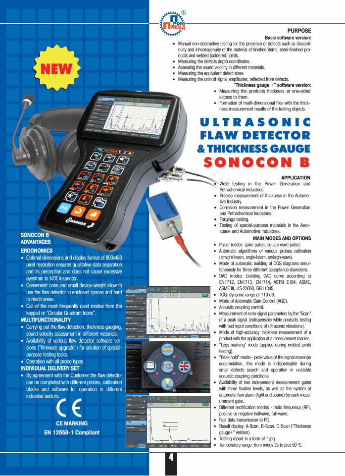
PURPOSE
SONOCON B
ADVANTAGES
ERGONOMICS
• Optimal dimensions and display format of 800x480pixel resolution ensures qualitative data separationand its perception and does not cause excessiveeyestrain to NDT inspector.
• Convenient case and small device weight allow touse the flaw detector in enclosed spaces and hardto reach areas.
• Call of the most frequently used modes from thekeypad or "Circular Quadrant Icons".
MULTIFUNCTIONALITY
• Carrying out the flaw detection, thickness gauging,sound velocity assessment in different materials.
• Availability of various flaw detector software ver�sions ("firmware upgrade") for solution of special�purpose testing tasks.
• Operation with all probe types.INDIVIDUAL DELIVERY SET
• By agreement with the Customer the flaw detectorcan be completed with different probes, calibrationblocks and software for operation in differentindustrial sectors.
Basic software version:
• Manual non�destructive testing for the presence of defects such as disconti�nuity and inhomogenuity of the material of finished items, semi�finished pro�ducts and welded (soldered) joints.
• Measuring the defects depth coordinates.• Assessing the sound velocity in different materials.• Measuring the equivalent defect sizes.• Measuring the ratio of signal amplitudes, reflected from defects.
"Thickness gauge +" software version:
MAIN MODES AND OPTIONS
• Pulser modes: spike pulser, square wave pulser.• Automatic algorithms of various probes calibration
(straight�beam, angle�beam, rayleigh�wave).• Mode of automatic building of DGS diagrams simul�
taneously for three different acceptance diameters.• DAC modes: building DAC curve according to
EN1712, EN1713, EN1714, ASTM E164, ASME,ASME III, JIS 23060, GB11345.
• TCG: dynamic range of 110 dB.• Mode of Automatic Gain Control (AGC).• Acoustic coupling control.• Measurement of echo�signal parameters by the “Scan”
of a peak signal (indispensible while products testingwith bad input conditions of ultrasonic vibrations).
• Mode of high�accuracy thickness measurement of aproduct with the application of a measurement marker.
• “Legs marking” mode (applied during welded jointstesting).
• “Peak hold” mode � peak value of the signal envelopeaccumulation, this mode is indispensable duringsmall defects search and operation in unstableacoustic coupling conditions.
• Availability of two independent measurement gateswith three fixation levels, as well as the system ofautomatic flaw alarm (light and sound) by each meas�urement gate.
• Different rectification modes � radio frequency (RF),positive or negative halfwave, full�wave.
• Fast data transmission to PC.• Result display: A�Scan, B�Scan. C�Scan (“Thickness
gauge+” version).• Testing report in a form of *.jpg• Temperature range: from minus 25 to plus 50 0C.
®
APPLICATION
• Weld testing in the Power Generation andPetrochemical Industries.
• Precise measurement of thickness in the Automo�tive Industry.
• Corrosion measurement in the Power Generationand Petrochemical Industries.
• Forgings testing.• Testing of special�purpose materials in the Aero�
space and Automotive Industries.
• Measuring the products thickness at one�sidedaccess to them.
• Formation of multi�dimensional files with the thick�ness measurement results of the testing objects.
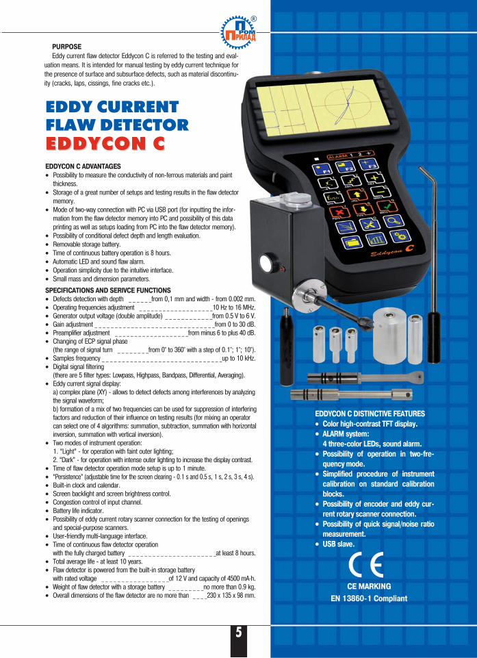
EDDY CURRENT FLAW DETECTOREDDYCON СEDDYCON С
EDDYCON C DISTINCTIVE FEATURES
• Color high�contrast TFT display.
•• ALARM system:
4 three�color LEDs, sound alarm.
•• Possibility of operation in two�fre�
quency mode.
•• Simplified procedure of instrument
calibration on standard calibration
blocks.
•• Possibility of encoder and eddy cur�
rent rotary scanner connection.
•• Possibility of quick signal/noise ratio
measurement.
•• USB slave.
EDDYCON C ADVANTAGES
• Possibility to measure the conductivity of non�ferrous materials and paintthickness.
• Storage of a great number of setups and testing results in the flaw detectormemory.
• Mode of two�way connection with PC via USB port (for inputting the infor�mation from the flaw detector memory into PC and possibility of this dataprinting as well as setups loading from PC into the flaw detector memory).
• Possibility of conditional defect depth and length evaluation.• Removable storage battery.• Time of continuous battery operation is 8 hours.• Automatic LED and sound flaw alarm.• Operation simplicity due to the intuitive interface.• Small mass and dimension parameters.
SPECIFICATIONS AND SERIVCE FUNCTIONS
• Defects detection with depth _ _ _ _ _ _from 0,1 mm and width � from 0.002 mm.• Operating frequencies adjustment _ _ _ _ _ _ _ _ _ _ _ _ _ _ _ _ _ _ _10 Hz to 16 МHz.• Generator output voltage (double amplitude) _ _ _ _ _ _ _ _ _ _ _ _from 0.5 V to 6 V. • Gain adjustment _ _ _ _ _ _ _ _ _ _ _ _ _ _ _ _ _ _ _ _ _ _ _ _ _ _ _ _ _ _from 0 to 30 dB.• Preamplifier adjustment _ _ _ _ _ _ _ _ _ _ _ _ _ _ _ _ _ _ _from minus 6 to plus 40 dB.• Changing of ECP signal phase
(the range of signal turn _ _ _ _ _ _ _ _from 0° to 360° with a step of 0.1°; 1°; 10°).• Samples frequency _ _ _ _ _ _ _ _ _ _ _ _ _ _ _ _ _ _ _ _ _ _ _ _ _ _ _ _ _ _up to 10 kHz.• Digital signal filtering
(there are 5 filter types: Lowpass, Highpass, Bandpass, Differential, Averaging).• Eddy current signal display:
a) complex plane (XY) � allows to detect defects among interferences by analyzingthe signal waveform; b) formation of a mix of two frequencies can be used for suppression of interferingfactors and reduction of their influence on testing results (for mixing an operatorcan select one of 4 algorithms: summation, subtraction, summation with horizontalinversion, summation with vertical inversion).
• Two modes of instrument operation: 1. “Light” � for operation with faint outer lighting; 2. “Dark” � for operation with intense outer lighting to increase the display contrast.
• Time of flaw detector operation mode setup is up to 1 minute.• “Persistence” (adjustable time for the screen clearing � 0.1 s and 0.5 s, 1 s, 2 s, 3 s, 4 s).• Built�in clock and calendar.• Screen backlight and screen brightness control.• Congestion control of input channel.• Battery life indicator.• Possibility of eddy current rotary scanner connection for the testing of openings
and special�purpose scanners.• User�friendly multi�language interface.• Time of continuous flaw detector operation
with the fully charged battery _ _ _ _ _ _ _ _ _ _ _ _ _ _ _ _ _ _ _ _ _ _at least 8 hours.• Total average life � at least 10 years.• Flaw detector is powered from the built�in storage battery
with rated voltage _ _ _ _ _ _ _ _ _ _ _ _ _ _ _ _ _of 12 V and capacity of 4500 mA·h.• Weight of flaw detector with a storage battery _ _ _ _ _ _ _ _ _no more than 0.9 kg.• Overall dimensions of the flaw detector are no more than _ _ _ _230 x 135 x 98 mm.
PURPOSE
Eddy current flaw detector Eddycon C is referred to the testing and eval�uation means. It is intended for manual testing by eddy current technique forthe presence of surface and subsurface defects, such as material discontinu�ity (cracks, laps, cissings, fine cracks etc.).
®
5
Б6
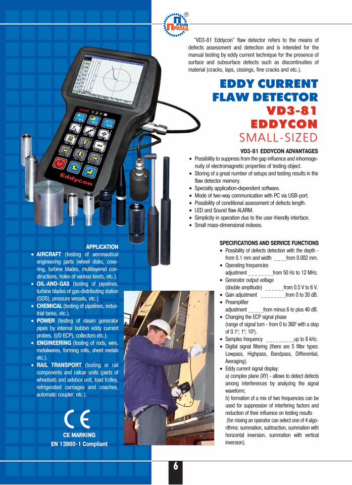
EDDY CURRENT FLAW DETECTOR
VD3�81 VD3�81 EDDYCON EDDYCON
SMALL�SIZEDSMALL�SIZED
SPECIFICATIONS AND SERVICE FUNCTIONS
• Possibility of defects detection with the depth �from 0.1 mm and width _ _ _ _from 0.002 mm.
• Operating frequencies adjustment _ _ _ _ _ _ _ _from 50 Hz to 12 MHz.
• Generator output voltage (double amplitude) _ _ _ _ _ _from 0.5 V to 6 V.
• Gain adjustment _ _ _ _ _ _ _ _from 0 to 30 dB.• Preamplifier
adjustment _ _ _ _ _from minus 6 to plus 40 dB.• Changing the ECP signal phase
(range of signal turn � from 0 to 3600 with a stepof 0.10; 10; 100).
• Samples frequency _ _ _ _ _ _ _ _ _up to 8 kHz.• Digital signal filtering (there are 5 filter types:
Lowpass, Highpass, Bandpass, Differential,Averaging).
• Eddy current signal display: a) complex plane (XY) � allows to detect defectsamong interferences by analyzing the signalwaveform; b) formation of a mix of two frequencies can beused for suppression of interfering factors andreduction of their influence on testing results(for mixing an operator can select one of 4 algo�rithms: summation, subtraction, summation withhorizontal inversion, summation with verticalinversion).
VD3�81 EDDYCON ADVANTAGES
• Possibility to suppress from the gap influence and inhomoge�nuity of electromagnetic properties of testing object.
• Storing of a great number of setups and testing results in theflaw detector memory.
• Specialty application�dependent software.• Mode of two�way communication with PC via USB�port.• Possibility of conditional assessment of defects length.• LED and Sound flaw ALARM.• Simplicity in operation due to the user�friendly interface.• Small mass�dimensional indexes.
APPLICATION
• AIRCRAFT (testing of aeronauticalengineering parts (wheel disks, cove�ring, turbine blades, multilayered con�structions, holes of various kinds, etc.).
• OIL�AND�GAS (testing of pipelines,turbine blades of gas�distributing station(GDS), pressure vessels, etc.).
• CHEMICAL (testing of pipelines, indus�trial tanks, etc.).
• POWER (testing of steam generatorpipes by internal bobbin eddy currentprobes, (I/D ECP), collectors etc.).
• ENGINEERING (testing of rods, wire,metalwares, forming rolls, sheet metalsetc.).
• RAIL TRANSPORT (testing or railcomponents and railcar units (parts ofwheelsets and axlebox unit, load trolley,refrigerated carriages and coaches,automatic coupler, etc.).
"VD3�81 Eddycon" flaw detector refers to the means ofdefects assessment and detection and is intended for themanual testing by eddy current technique for the presence ofsurface and subsurface defects such as discontinuities ofmaterial (cracks, laps, cissings, fine cracks and etc.).
1121
9
1314
15
6�7 1�5
22
8
23
1012
16�20
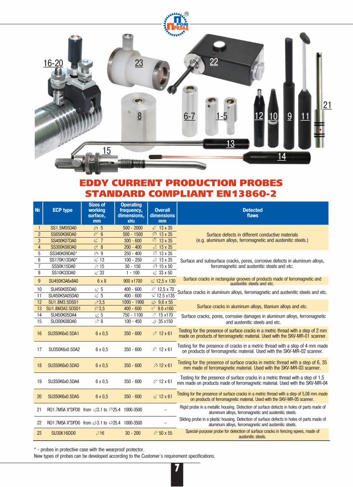
EDDY CURRENT PRODUCTION PROBES STANDARD COMPLIANT EN13860�2
Sizes of Operating№ ECP type working frequency, Overall Detected
surface, dimensions, dimensions flawsmm кHz mm
1 SS1.5M05DA0 5 500 � 2000 13 x 352 SS650K06DA0 6 500 � 1500 13 x 353 SS400K07DA0 7 300 � 600 13 x 354 SS300K08DA0 8 200 � 400 13 x 355 SS340K09DA0* 9 250 � 400 13 x 356 SS170K13DA0* 13 100 � 250 13 x 357 SS50K15DA0 15 50 � 150 15 x 508 SS10K33DA0 33 1 � 100 33 x 50
9 SU450K3А6х8A0 6 x 8 900 x1700 12,5 x 130
10 SU450K05DA0 5 400 � 600 12,5 x 7011 SU450K5А05DA0 5 400 � 600 12.5 x13512 SU1.8М3.5DS01 3,5 1000 � 1900 9,6 x 5513 SU1.8М3А3.5DS01 3,5 400 � 600 9.6 x16014 SU450K05DA4 5 750 � 1100 15 x17015 SU300K08DA0 8 100 � 450 35 x150
16 SU350K6x0.5DA1 6 x 0,5 350 � 600 12 x 61
17 SU350K6x0.5DA2 6 x 0,5 350 � 600 12 x 61
18 SU350K6x0.5DA3 6 x 0,5 350 � 600 12 x 61
19 SU350K6x0.5DA4 6 x 0,5 350 � 600 12 x 61
20 SU350K6x0.5DA5 6 x 0,5 350 � 600 12 x 61
21 RO1.7M5A�X”DFD0 from 3.1 to 25.4 1000�3500 —
22 RO1.7M5A�X”DFD0 from 3.1 to 25.4 1000�3500 —
23 SU30К16DD0 16 30 � 200 50 x 55
Surface defects in different conductive materials (e.g. aluminum alloys, ferromagnetic and austenitic steels.)
Surface and subsurface cracks, pores, corrosive defects in aluminum alloys,ferromagnetic and austenitic steels and etc.
Surface cracks in rectangular grooves of products made of ferromagnetic andaustenitic steels and etc.
Surface cracks in aluminum alloys, ferromagnetic and austenitic steels and etc.
Surface cracks in aluminum alloys, titanium alloys and etc.
Surface cracks, pores, corrosive damages in aluminum alloys, ferromagneticand austenitic steels and etc.
Testing for the presence of cracks in a metric thread with a step of 4 mm madeon products of ferromagnetic material. Used with the SKV�MR�02 scanner.
Testing for the presence of surface cracks in metric thread with a step of 6, 35mm made of ferromagnetic material. Used with the SKV�MR�03 scanner.
Testing for the presence of surface cracks in a metric thread with a step of 1,5mm made on products made of ferromagnetic material. Used with the SKV�MR�04
Testing for the presence of surface cracks in a metric thread with a step of 5,08 mm madeon products of ferromagnetic material. Used with the SKV�MR�05 scanner.
Rigid probe in a metallic housing. Detection of surface defects in holes of parts made ofaluminum alloys, ferromagnetic and austenitic steels.
Sliding probe in a plastic housing. Detection of surface defects in holes of parts made ofaluminum alloys, ferromagnetic and austenitic steels.
Special�purpose probe for detection of surface cracks in fencing epees, made ofaustenitic steels.
Testing for the presence of surface cracks in a metric thread with a step of 2 mmmade on products of ferromagnetic material. Used with the SKV�MR�01 scanner.
* � probes in protective case with the wearproof protector.New types of probes can be developed according to the Customer`s requirement specifications.
7
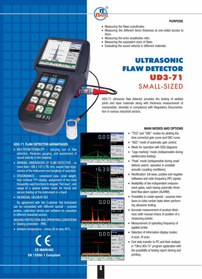
UD3�71 FLAW DETECTOR ADVANTAGES
• MULTIFUNCTIONALITY — carrying out of flawdetection, thickness gauging, and assessment ofsound velocity in the material.
• MINIMAL DIMENSIONS OF FLAW DETECTOR � nomore than (188 x 107 x 78) mm, assure high ergo�nomics of the instrument and simplicity of operation.
• ERGONOMICS — convenient case, small weight,high�contrast TFT�display, assignment of the mostfrequently used functions to keypad "hot keys", andusage of a special leather cover for handy andsecure holding of the instrument in a hand.
• INDIVIDUAL DELIVERY SET
By agreement with the Customer the instrumentcan be completed with different special � purposeprobes, calibration blocks and software for operationin different industrial sectors.
SEALING PROTECTION AND OPERATING CONDITIONS• Sealing protection � IP65.
• Ambient temperature � minus 30 to plus 45°C.
• Measuring the flaws coordinates.• Measuring the different items thickness at one�sided access to
them.• Measuring the echo amplitudes ratio.• Measuring the equivalent sizes of flaws.• Evaluating the sound velocity in different materials.
ULTRASONIC FLAW DETECTOR
UD3�71UD3�71SMALL�SIZED
PURPOSE
UD3�71 ultrasonic flaw detector provides the testing of weldedjoints and base materials along with thickness measurement ofmonometals, bimetals in compliance with Regulatory Documenta�tion in various industrial sectors.
MAIN MODES AND OPTIONS
• “TCG” and "DAC" modes for plotting thetime corrected gain curve and DAC curve.
• “AGC” mode of automatic gain control.• Mode for operation with DGS diagrams• "Legs marking" mode (indispensable during
welded joins testing).• “Peak” mode (indispensible during small
defects search, operation in unstableacoustic coupling conditions).
• Rectification: full wave, positive and negativehalfwaves and radio frequency (RF) signals.
• Availability of two independent measure�ment gates, each having automatic three�level flaw alarm system (ALARM).
• Possibility to create special � purpose inter�faces to solve certain tasks when perform�ing ultrasonic testing.
• Accurate measurement of product thick�ness (with manual choice of position of ameasuring pointer.
• Measurement of operating frequency ofapplied probe.
• Selection of information display modes: A�scan, B�scan.
• Fast data transfer to PC and their analysisin “Ultra UDx�7x” program application withthe possibility of testing report storing andprinting.
8
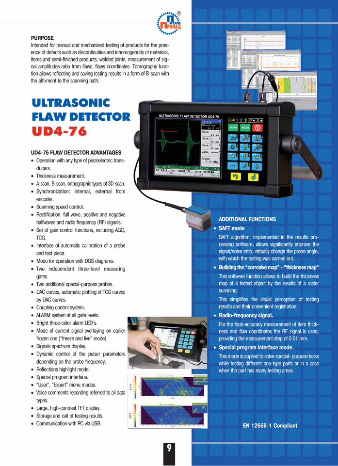
UD4�76 FLAW DETECTOR ADVANTAGES
• Operation with any type of piezoelectric trans�ducers.
• Thickness measurement.• A�scan, B�scan, orthographic types of 3D�scan.• Synchronization: internal, external from
encoder.• Scanning speed control.• Rectification: full wave, positive and negative
halfwaves and radio frequency (RF) signals.• Set of gain control functions, including AGC,
TCG.• Interface of automatic calibration of a probe
and test piece.• Mode for operation with DGS diagrams.• Two independent three�level measuring
gates.• Two additional special�purpose probes.• DAC curves, automatic plotting of TCG curves
by DAC curves. • Coupling control system.• ALARM system at all gate levels. • Bright three�color alarm LED`s.• Mode of current signal overlaying on earlier
frozen one (“freeze and live” mode).• Signals spectrum display.• Dynamic control of the pulser parameters
depending on the probe frequency.• Reflections highlight mode.• Special program interface.• “User”, “Expert” menu modes.• Voice comments recording referred to all data
types.• Large, high�contrast TFT display.• Storage and call of testing results.• Communication with PC via USB.
ULTRASONIC FLAW DETECTORUD4�76UD4�76
PURPOSE
Intended for manual and mechanized testing of products for the pres�ence of defects such as discontinuities and inhomogenuity of materials,items and semi�finished products, welded joints, measurement of sig�nal amplitudes ratio from flaws, flaws coordinates. Tomography func�tion allows reflecting and saving testing results in a form of B�scan withthe affixment to the scanning path.
ADDITIONAL FUNCTIONS
• SAFT mode
SAFT algorithm, implemented in the results pro�cessing software, allows significantly improve thesignal/noise ratio, virtually change the probe angle,with which the testing was carried out.
• Building the “corrosive map” � “thickness map”
This software function allows to build the thicknessmap of a tested object by the results of a rasterscanning.
This simplifies the visual perception of testingresults and their convenient registration.
• Radio�frequency signal.
For the high�accuracy measurement of item thick�ness and flaw coordinates the RF signal is used,providing the measurement step of 0.01 mm.
• Special program interface mode.
This mode is applied to solve special� purpose taskswhile testing different one�type parts or in a casewhen the part has many testing areas.
9
EN 12668�1 Compliant
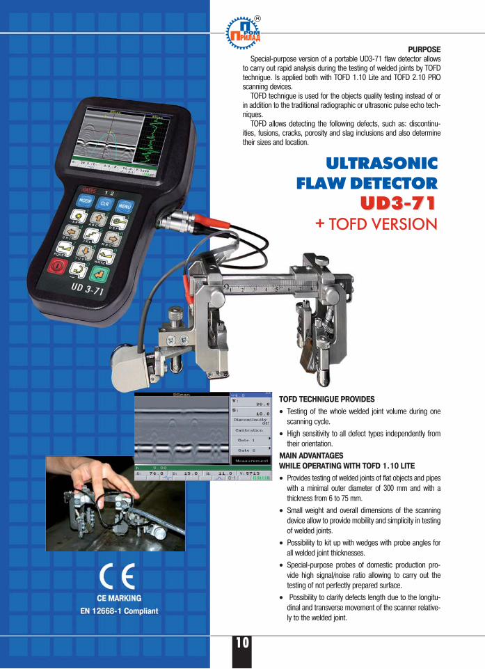
PURPOSE
Special�purpose version of a portable UD3�71 flaw detector allowsto carry out rapid analysis during the testing of welded joints by TOFDtechnigue. Is applied both with TOFD 1.10 Lite and TOFD 2.10 PROscanning devices.
TOFD technigue is used for the objects quality testing instead of orin addition to the traditional radiographic or ultrasonic pulse echo tech�niques.
TOFD allows detecting the following defects, such as: discontinu�ities, fusions, cracks, porosity and slag inclusions and also determinetheir sizes and location.
ULTRASONIC FLAW DETECTOR
UD3�71UD3�71+ TOFD VERSION
TOFD TECHNIGUE PROVIDES
• Testing of the whole welded joint volume during onescanning cycle.
• High sensitivity to all defect types independently fromtheir orientation.
MAIN ADVANTAGES
WHILE OPERATING WITH TOFD 1.10 LITE
• Provides testing of welded joints of flat objects and pipeswith a minimal outer diameter of 300 mm and with athickness from 6 to 75 mm.
• Small weight and overall dimensions of the scanningdevice allow to provide mobility and simplicity in testingof welded joints.
• Possibility to kit up with wedges with probe angles forall welded joint thicknesses.
• Special�purpose probes of domestic production pro�vide high signal/noise ratio allowing to carry out thetesting of not perfectly prepared surface.
• Possibility to clarify defects length due to the longitu�dinal and transverse movement of the scanner relative�ly to the welded joint.
10
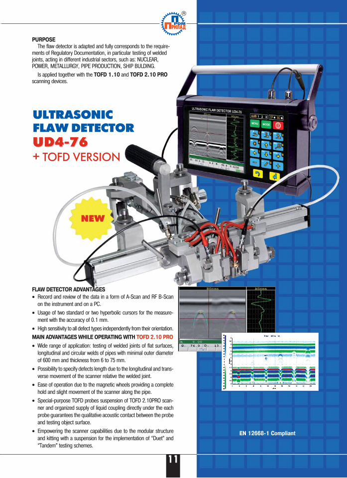
PURPOSE
The flaw detector is adapted and fully corresponds to the require�ments of Regulatory Documentation, in particular testing of weldedjoints, acting in different industrial sectors, such as: NUCLEAR,POWER, METALLURGY, PIPE PRODUCTION, SHIP BULDING.
Is applied together with the TOFD 1.10 and TOFD 2.10 PRO
scanning devices.
ULTRASONIC FLAW DETECTORUD4�76UD4�76+ TOFD VERSION
FLAW DETECTOR ADVANTAGES
• Record and review of the data in a form of A�Scan and RF B�Scanon the instrument and on a PC.
• Usage of two standard or two hyperbolic cursors for the measure�ment with the accuracy of 0.1 mm.
• High sensitivity to all defect types independently from their orientation.
MAIN ADVANTAGES WHILE OPERATING WITH TOFD 2.10 PRO
• Wide range of application: testing of welded joints of flat surfaces,longitudinal and circular welds of pipes with minimal outer diameterof 600 mm and thickness from 6 to 75 mm.
• Possibility to specify defects length due to the longitudinal and trans�verse movement of the scanner relative the welded joint.
• Ease of operation due to the magnetic wheels providing a completehold and slight movement of the scanner along the pipe.
• Special�purpose TOFD probes suspension of TOFD 2.10PRO scan�ner and organized supply of liquid coupling directly under the eachprobe guarantees the qualitative acoustic contact between the probeand testing object surface.
• Empowering the scanner capabilities due to the modular structureand kitting with a suspension for the implementation of “Duet” and“Tandem” testing schemes.
NEW
11
Б
EN 12668�1 Compliant
PURPOSE
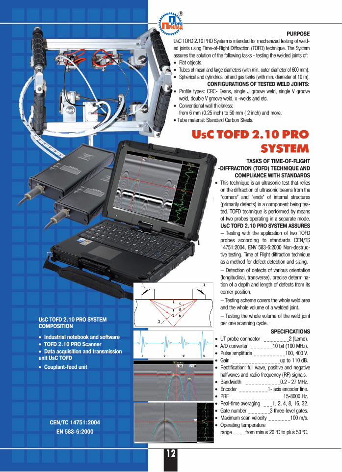
UsC TOFD 2.10 PRO System is intended for mechanized testing of weld�ed joints using Time�of�Flight Diffraction (TOFD) technique. The Systemassures the solution of the following tasks � testing the welded joints of:• Flat objects.• Tubes of mean and large diameters (with min. outer diameter of 600 mm).• Spherical and cylindrical oil and gas tanks (with min. diameter of 10 m).
CONFIGURATIONS OF TESTED WELD JOINTS:
• Profile types: CRC� Evans, single J groove weld, single V grooveweld, double V groove weld, x �welds and etc.
• Conventional wall thickness: from 6 mm (0.25 inch) to 50 mm ( 2 inch) and more.
• Tube material: Standard Carbon Steels.
UsC TOFD 2.10 PRO SYSTEM
UsC TOFD 2.10 PRO SYSTEM
COMPOSITION
• Industrial notebook and software
• TOFD 2.10 PRO Scanner
• Data acquisition and transmission
unit UsC TOFD
• Couplant�feed unit
TASKS OF TIME�OF�FLIGHT
�DIFFRACTION (TOFD) TECHNIQUE AND
COMPLIANCE WITH STANDARDS
• This technique is an ultrasonic test that relieson the diffraction of ultrasonic beams from the“corners” and “ends” of internal structures(primarily defects) in a component being tes�ted. TOFD technique is performed by meansof two probes operating in a separate mode.UsC TOFD 2.10 PRO SYSTEM ASSURES
— Testing with the application of two TOFDprobes according to standards CEN/TS14751:2004, ENV 583�6:2000 Non�destruc�tive testing. Time of Flight diffraction techniqueas a method for defect detection and sizing.
— Detection of defects of various orientation(longitudinal, transverse), precise determina�tion of a depth and length of defects from itscorner position.
— Testing scheme covers the whole weld areaand the whole volume of a welded joint.
— Testing the whole volume of the weld jointper one scanning cycle.
SPECIFICATIONS
• UT probe connector _ _ _ _ _ _ _ _2 (Lemo).• A/D converter _ _ _ _ _ _ _10 bit (100 MHz).• Pulse amplitude _ _ _ _ _ _ _ _ _ _100, 400 V.• Gain _ _ _ _ _ _ _ _ _ _ _ _ _ _ _up to 110 dB.• Rectification: full wave, positive and negative
halfwaves and radio frequency (RF) signals.• Bandwidth _ _ _ _ _ _ _ _ _ _ _0.2 � 27 MHz.• Encoder _ _ _ _ _ _ _ _ _1� axis encoder line.• PRF _ _ _ _ _ _ _ _ _ _ _ _ _ _ _ _15�8000 Hz.• Real�time averaging _ _ _1, 2, 4, 8, 16, 32.• Gate number _ _ _ _ _ _ _3 three�level gates.• Maximum scan velocity _ _ _ _ _ _ _100 m/s.• Operating temperature
range _ _ _ _from minus 20 0C to plus 50 0C.
12
CEN/TC 14751:2004
EN 583�6:2000
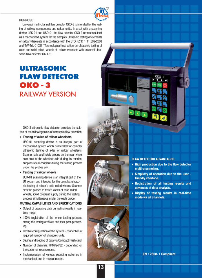
ULTRASONIC FLAW DETECTOROKO � 3RAILWAY VERSION
FLAW DETECTOR ADVANTAGES
• High production due to the flaw detector
multi�channeling.
• Simplicity of operation due to the user �
friendly interface.
• Registration of all testing results and
advances of data analysis.
• Display of testing results in real�time
mode via all channels.
OKO�3 ultrasonic flaw detector provides the solu�tion of the following tasks of ultrasonic flaw detection:
• Testing of axles of railcar wheelsets
USO�01 scanning device is an integral part ofmechanized system which is intended for complexultrasonic testing of axles of railcar wheelsets.Scanner sets and holds probes on the near wheelseat area of the wheelset axle during its rotation,supplies liquid couplant during the testing processunder the probes unit.
• Testing of railcar wheels
USK�01 scanning device is an integral part of theUT system and intended for the complex ultraso�nic testing of railcar`s solid�rolled wheels. Scannersets the probes to tested zones of solid�rolledwheels, liquid couplant supply during the testingprocess simultaneous under the each probe.
MUTUAL CAPABILITIES AND SPECIFICATIONS
• Output of operating data on testing results in real�time mode.
• 100% registration of the whole testing process,saving the testing archives and their post�process�ing.
• Flexible configuration of the system � connection ofrequired number of ultrasonic units.
• Saving and loading of data via Compact Flesh card.
• Number of channels: 8/16/24/32 � depending onthe customer requirements.
• Implementation of various sounding schemes inmechanized and in manual modes.
PURPOSE
Universal multi�channel flaw detector OKO�3 is intended for the test�ing of railway components and railcar units. In a set with a scanningdevice USK�01 and USO�01 the flaw detector OKO�3 represents itselfas a mechanized system for the complex ultrasonic testing of elementsof railcar wheelsets in accordance with the STO RZhD 1.11.002�2008and TsV�TsL�01031 "Technological instruction on ultrasonic testing ofaxles and solid�rolled wheels of railcar wheelsets with universal ultra�sonic flaw detector OKO�3".
13
EN 12668�1 Compliant
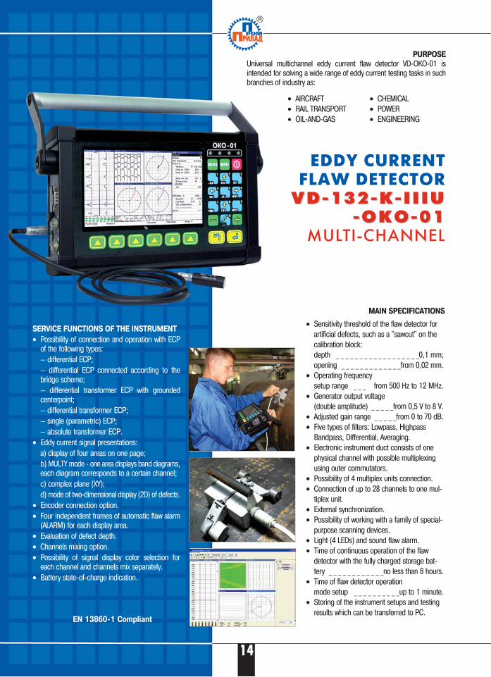
PURPOSE
Universal multichannel eddy current flaw detector VD�OKO�01 isintended for solving a wide range of eddy current testing tasks in suchbranches of industry as:
EDDY CURRENT FLAW DETECTOR
V D � 1 3 2 � K � I I I UV D � 1 3 2 � K � I I I U� O K O � 0 1� O K O � 0 1
MULTI�CHANNEL
MAIN SPECIFICATIONS
• Sensitivity threshold of the flaw detector forartificial defects, such as a "sawcut" on thecalibration block:depth _ _ _ _ _ _ _ _ _ _ _ _ _ _ _ _ _ _0,1 mm;opening _ _ _ _ _ _ _ _ _ _ _ _ _from 0,02 mm.
• Operating frequency setup range _ _ _ from 500 Hz to 12 MHz.
• Generator output voltage(double amplitude) _ _ _ _ _from 0,5 V to 8 V.
• Adjusted gain range _ _ _ _ _from 0 to 70 dB.• Five types of filters: Lowpass, Highpass
Bandpass, Differential, Averaging.• Electronic instrument duct consists of one
physical channel with possible multiplexingusing outer commutators.
• Possibility of 4 multiplex units connection. • Connection of up to 28 channels to one mul�
tiplex unit.• External synchronization.• Possibility of working with a family of special�
purpose scanning devices. • Light (4 LEDs) and sound flaw alarm. • Time of continuous operation of the flaw
detector with the fully charged storage bat�tery _ _ _ _ _ _ _ _ _ _ _ _no less than 8 hours.
• Time of flaw detector operationmode setup _ _ _ _ _ _ _ _ _ _up to 1 minute.
• Storing of the instrument setups and testingresults which can be transferred to PC.
SERVICE FUNCTIONS OF THE INSTRUMENT
• Possibility of connection and operation with ECPof the following types:— differential ECP;— differential ECP connected according to thebridge scheme;— differential transformer ECP with groundedcenterpoint;— differential transformer ECP;— single (parametric) ECP;— absolute transformer ECP.
• Eddy current signal presentations:a) display of four areas on one page;b) MULTY mode � one area displays band diagrams,each diagram corresponds to a certain channel;c) complex plane (XY);d) mode of two�dimensional display (2D) of defects.
• Encoder connection option.• Four independent frames of automatic flaw alarm
(ALARM) for each display area.• Evaluation of defect depth.• Channels mixing option.• Possibility of signal display color selection for
each channel and channels mix separately.• Battery state�of�charge indication.
• AIRCRAFT• RAIL TRANSPORT• OIL�AND�GAS
• CHEMICAL• POWER• ENGINEERING
14
EN 13860�1 Compliant
15
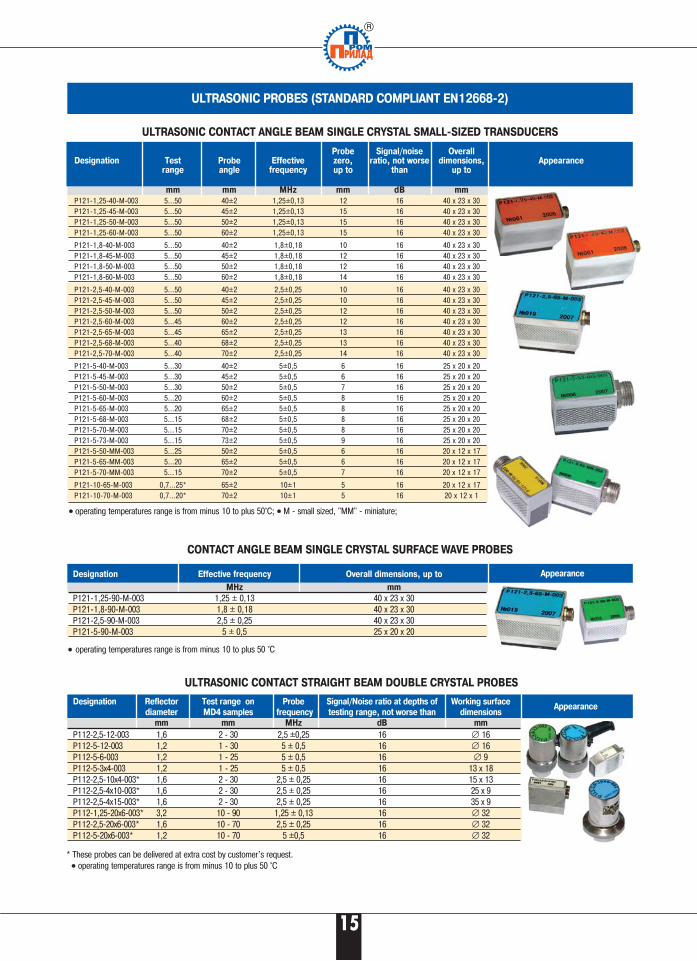
•• operating temperatures range is from minus 10 to plus 50°C; •• M � small sized, "MM" � miniature;
Probe Signal/noise Overall Designation Test Probe Effective zero, ratio, not worse dimensions,
range angle frequency up to than up to
mm mm MHz mm dB mm
P121�1,25�40�М�003 5...50 40±2 1,25±0,13 12 16 40 х 23 х 30P121�1,25�45�М�003 5...50 45±2 1,25±0,13 15 16 40 х 23 х 30P121�1,25�50�М�003 5...50 50±2 1,25±0,13 15 16 40 х 23 х 30P121�1,25�60�М�003 5...50 60±2 1,25±0,13 15 16 40 х 23 х 30
P121�1,8�40�М�003 5...50 40±2 1,8±0,18 10 16 40 х 23 х 30P121�1,8�45�М�003 5...50 45±2 1,8±0,18 12 16 40 х 23 х 30P121�1,8�50�М�003 5...50 50±2 1,8±0,18 12 16 40 х 23 х 30P121�1,8�60�М�003 5...50 60±2 1,8±0,18 14 16 40 х 23 х 30
P121�2,5�40�М�003 5...50 40±2 2,5±0,25 10 16 40 х 23 х 30P121�2,5�45�М�003 5...50 45±2 2,5±0,25 10 16 40 х 23 х 30P121�2,5�50�М�003 5...50 50±2 2,5±0,25 12 16 40 х 23 х 30P121�2,5�60�М�003 5...45 60±2 2,5±0,25 12 16 40 х 23 х 30P121�2,5�65�М�003 5...45 65±2 2,5±0,25 13 16 40 х 23 х 30P121�2,5�68�М�003 5...40 68±2 2,5±0,25 13 16 40 х 23 х 30P121�2,5�70�М�003 5...40 70±2 2,5±0,25 14 16 40 х 23 х 30
P121�5�40�М�003 5...30 40±2 5±0,5 6 16 25 х 20 х 20P121�5�45�М�003 5...30 45±2 5±0,5 6 16 25 х 20 х 20P121�5�50�М�003 5...30 50±2 5±0,5 7 16 25 х 20 х 20P121�5�60�М�003 5...20 60±2 5±0,5 8 16 25 х 20 х 20P121�5�65�М�003 5...20 65±2 5±0,5 8 16 25 х 20 х 20P121�5�68�М�003 5...15 68±2 5±0,5 8 16 25 х 20 х 20P121�5�70�М�003 5...15 70±2 5±0,5 8 16 25 х 20 х 20P121�5�73�М�003 5...15 73±2 5±0,5 9 16 25 х 20 х 20P121�5�50�ММ�003 5...25 50±2 5±0,5 6 16 20 х 12 х 17P121�5�65�ММ�003 5...20 65±2 5±0,5 6 16 20 х 12 х 17P121�5�70�ММ�003 5...15 70±2 5±0,5 7 16 20 х 12 х 17
P121�10�65�М�003 0,7...25* 65±2 10±1 5 16 20 х 12 х 17P121�10�70�М�003 0,7...20* 70±2 10±1 5 16 20 х 12 х 1
ULTRASONIC CONTACT ANGLE BEAM SINGLE CRYSTAL SMALL�SIZED TRANSDUCERS
ULTRASONIC PROBES (STANDARD COMPLIANT EN12668�2)
Appearance
Designation Effective frequency Overall dimensions, up to
MHz mm
P121�1,25�90�М�003 1,25 ± 0,13 40 х 23 х 30P121�1,8�90�М�003 1,8 ± 0,18 40 х 23 х 30P121�2,5�90�М�003 2,5 ± 0,25 40 х 23 х 30P121�5�90�М�003 5 ± 0,5 25 х 20 х 20
CONTACT ANGLE BEAM SINGLE CRYSTAL SURFACE WAVE PROBES
ULTRASONIC CONTACT STRAIGHT BEAM DOUBLE CRYSTAL PROBES
•• operating temperatures range is from minus 10 to plus 50 °C
* These probes can be delivered at extra cost by customer's request.•• operating temperatures range is from minus 10 to plus 50 °C
Designation Reflector Test range on Probe Signal/Noise ratio at depths of Working surface
diameter MD4 samples frequency testing range, not worse than dimensions
mm mm MHz dB mm
P112�2,5�12�003 1,6 2 � 30 2,5 ±0,25 16 ∅ 16P112�5�12�003 1,2 1 � 30 5 ± 0,5 16 ∅ 16P112�5�6�003 1,2 1 � 25 5 ± 0,5 16 ∅ 9P112�5�3х4�003 1,2 1 � 25 5 ± 0,5 16 13 х 18P112�2,5�10х4�003* 1,6 2 � 30 2,5 ± 0,25 16 15 х 13P112�2,5�4х10�003* 1,6 2 � 30 2,5 ± 0,25 16 25 х 9P112�2,5�4х15�003* 1,6 2 � 30 2,5 ± 0,25 16 35 х 9P112�1,25�20х6�003* 3,2 10 � 90 1,25 ± 0,13 16 ∅ 32P112�2,5�20х6�003* 1,6 10 � 70 2,5 ± 0,25 16 ∅ 32P112�5�20х6�003* 1,2 10 � 70 5 ±0,5 16 ∅ 32
Appearance
Appearance
16
SPECIAL CONTACT DOUBLE CRYSTAL CREEPING WAVE PROBES
Test Probe Effective Probe OverallDesignation range angle frequency zero, dimensions,
up to up to
mm MHz mm
*P122�2,5�65�GV�003 5 � 50 65 ± 2 2,5 ± 0,25 14 35 х 23 х 28
ULTRASONIC CONTACT STRAIGHT BEAM DOUBLE CRYSTAL PROBES FOR THICKNESS GAUGING OF TURBINE BLADES
* These probes can be delivered at extra cost.•• operating temperatures range is from minus 10 to plus 50 °C
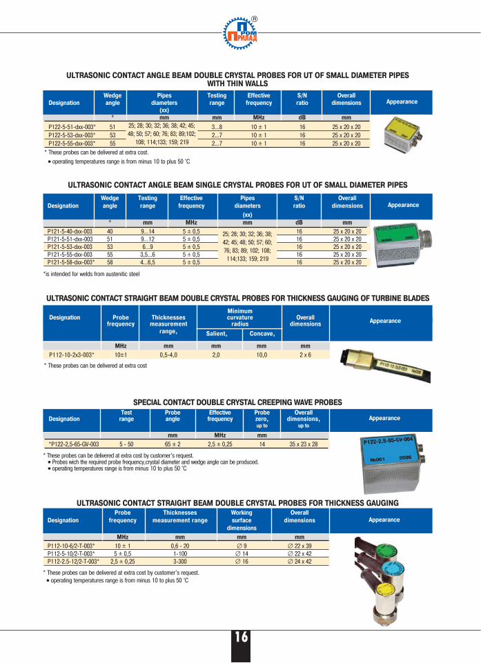
ULTRASONIC CONTACT ANGLE BEAM DOUBLE CRYSTAL PROBES FOR UT OF SMALL DIAMETER PIPES WITH THIN WALLS
* These probes can be delivered at extra cost
Wedge Testing Effective Pipes S/N Overall
Designation angle range frequency diameters ratio dimensions
(хх)0 mm MHz mm dB mm
P121�5�40�dхх�003 40 9…14 5 ± 0,5 16 25 х 20 х 20P121�5�51�dхх�003 51 9…12 5 ± 0,5 16 25 х 20 х 20P121�5�53�dхх�003 53 6…9 5 ± 0,5 16 25 х 20 х 20P121�5�55�dхх�003 55 3,5…6 5 ± 0,5 16 25 х 20 х 20P121�5�58�dхх�003* 58 4…6,5 5 ± 0,5 16 25 х 20 х 20
ULTRASONIC CONTACT ANGLE BEAM SINGLE CRYSTAL PROBES FOR UT OF SMALL DIAMETER PIPES
*is intended for welds from austenitic steel
MinimumDesignation Probe Thicknesses curvature Overall
frequency measurement radius dimensions
range,
MHz mm mm mm mm
P112�10�2х3�003* 10±1 0,5�4,0 2,0 10,0 2 х 6
* These probes can be delivered at extra cost by customer's request.•• Probes wich the required probe frequency,crystal diameter and wedge angle can be produced. •• operating temperatures range is from minus 10 to plus 50 °C
Probe Thicknesses Working Overall
Designation frequency measurement range surface dimensions
dimensions
MHz mm mm mm
P112�10�6/2�Т�003* 10 ± 1 0,6 � 20 ∅ 9 ∅ 22 х 39P112�5�10/2�Т�003* 5 ± 0,5 1�100 ∅ 14 ∅ 22 х 42P112�2.5�12/2�Т�003* 2,5 ± 0,25 3�300 ∅ 16 ∅ 24 х 42
ULTRASONIC CONTACT STRAIGHT BEAM DOUBLE CRYSTAL PROBES FOR THICKNESS GAUGING
* These probes can be delivered at extra cost by customer's request.•• operating temperatures range is from minus 10 to plus 50 °C
Appearance
Appearance
Appearance
Appearance
Appearance
Salient, Concave,
Wedge Pipes Testing Effective S/N Overall
Designation angle diameters range frequency ratio dimensions
(хх)0 mm mm MHz dB mm
P122�5�51�dхх�003* 51 3…8 10 ± 1 16 25 х 20 х 20 P122�5�53�dхх�003* 53 2…7 10 ± 1 16 25 х 20 х 20 P122�5�55�dхх�003* 55 2…7 10 ± 1 16 25 х 20 х 20
25; 28; 30; 32; 36; 38; 42; 45;48; 50; 57; 60; 76; 83; 89;102;
108; 114;133; 159; 219
25; 28; 30; 32; 36; 38;42; 45; 48; 50; 57; 60;76; 83; 89; 102; 108;114;133; 159; 219
17
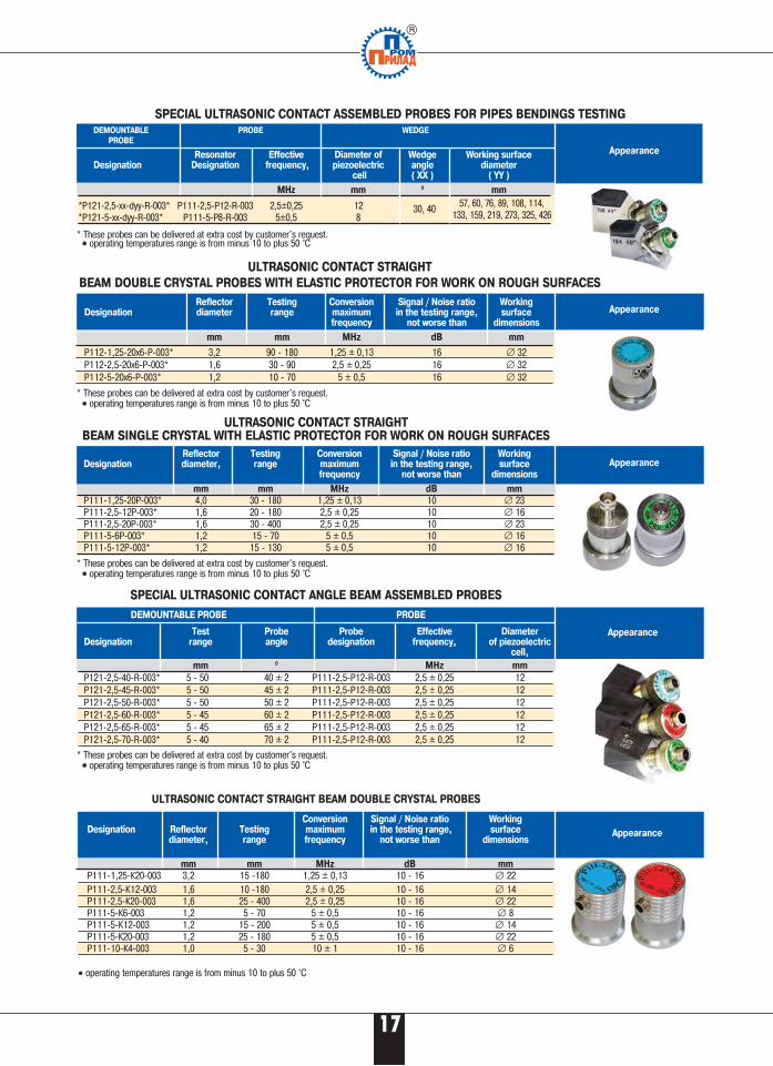
SPECIAL ULTRASONIC CONTACT ASSEMBLED PROBES FOR PIPES BENDINGS TESTING
• operating temperatures range is from minus 10 to plus 50 °C
ULTRASONIC CONTACT STRAIGHT BEAM DOUBLE CRYSTAL PROBES
SPECIAL ULTRASONIC CONTACT ANGLE BEAM ASSEMBLED PROBES
DEMOUNTABLE PROBE PROBE
Test Probe Probe Effective Diameter Designation range angle designation frequency, of piezoelectric
cell,
mm 0 MHz mm
P121�2,5�40�R�003* 5 � 50 40 ± 2 P111�2,5�P12�R�003 2,5 ± 0,25 12P121�2,5�45�R�003* 5 � 50 45 ± 2 P111�2,5�P12�R�003 2,5 ± 0,25 12P121�2,5�50�R�003* 5 � 50 50 ± 2 P111�2,5�P12�R�003 2,5 ± 0,25 12P121�2,5�60�R�003* 5 � 45 60 ± 2 P111�2,5�P12�R�003 2,5 ± 0,25 12P121�2,5�65�R�003* 5 � 45 65 ± 2 P111�2,5�P12�R�003 2,5 ± 0,25 12P121�2,5�70�R�003* 5 � 40 70 ± 2 P111�2,5�P12�R�003 2,5 ± 0,25 12
DEMOUNTABLE PROBE WEDGE
PROBE
Resonator Effective Diameter of Wedge Working surfaceDesignation Designation frequency, piezoelectric angle diameter
cell ( XX ) ( YY )
MHz mm 0 mm
*P121�2,5�хх�dyy�R�003* P111�2,5�P12�R�003 2,5±0,25 12*P121�5�хх�dyy�R�003* P111�5�P8�R�003 5±0,5 8 30, 40
* These probes can be delivered at extra cost by customer's request. •• operating temperatures range is from minus 10 to plus 50 °C
Reflector Testing Conversion Signal / Noise ratio WorkingDesignation diameter, range maximum in the testing range, surface
frequency not worse than dimensions
mm mm MHz dB mm
P111�1,25�20P�003* 4,0 30 � 180 1,25 ± 0,13 10 ∅ 23P111�2,5�12P�003* 1,6 20 � 180 2,5 ± 0,25 10 ∅ 16P111�2,5�20P�003* 1,6 30 � 400 2,5 ± 0,25 10 ∅ 23P111�5�6P�003* 1,2 15 � 70 5 ± 0,5 10 ∅ 16P111�5�12P�003* 1,2 15 � 130 5 ± 0,5 10 ∅ 16
* These probes can be delivered at extra cost by customer's request. •• operating temperatures range is from minus 10 to plus 50 °C
ULTRASONIC CONTACT STRAIGHT BEAM SINGLE CRYSTAL WITH ELASTIC PROTECTOR FOR WORK ON ROUGH SURFACES
* These probes can be delivered at extra cost by customer's request. •• operating temperatures range is from minus 10 to plus 50 °C
* These probes can be delivered at extra cost by customer's request.•• operating temperatures range is from minus 10 to plus 50 °C
Reflector Testing Conversion Signal / Noise ratio WorkingDesignation diameter range maximum in the testing range, surface
frequency not worse than dimensions
mm mm MHz dB mm
P112�1,25�20x6�P�003* 3,2 90 � 180 1,25 ± 0,13 16 ∅ 32P112�2,5�20x6�P�003* 1,6 30 � 90 2,5 ± 0,25 16 ∅ 32P112�5�20x6�P�003* 1,2 10 � 70 5 ± 0,5 16 ∅ 32
ULTRASONIC CONTACT STRAIGHT
BEAM DOUBLE CRYSTAL PROBES WITH ELASTIC PROTECTOR FOR WORK ON ROUGH SURFACES
Appearance
Appearance
Appearance
Appearance
Appearance
57, 60, 76, 89, 108, 114,133, 159, 219, 273, 325, 426
30, 40
Conversion Signal / Noise ratio WorkingDesignation Reflector Testing maximum in the testing range, surface
diameter, range frequency not worse than dimensions
mm mm MHz dB mm
P111�1,25�К20�003 3,2 15 �180 1,25 ± 0,13 10 � 16 ∅ 22P111�2,5�К12�003 1,6 10 �180 2,5 ± 0,25 10 � 16 ∅ 14P111�2,5�К20�003 1,6 25 � 400 2,5 ± 0,25 10 � 16 ∅ 22P111�5�К6�003 1,2 5 � 70 5 ± 0,5 10 � 16 ∅ 8P111�5�К12�003 1,2 15 � 200 5 ± 0,5 10 � 16 ∅ 14P111�5�К20�003 1,2 25 � 180 5 ± 0,5 10 � 16 ∅ 22P111�10�К4�003 1,0 5 � 30 10 ± 1 10 � 16 ∅ 6
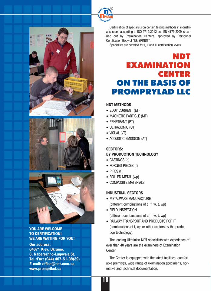
NDT EXAMINATION
CENTERON THE BASIS OF
PROMPRYLAD LLC
NDT METHODS
• EDDY CURRENT (ET)• MAGNETIC PARTICLE (MT)• PENETRANT (PT)• ULTRASONIC (UT)• VISUAL (VT)• ACOUSTIC EMISSION (AT)
SECTORS:
BY PRODUCTION TECHNOLOGY
• CASTINGS (c) • FORGED PIECES (f)• PIPES (t)• ROLLED METAL (wp)• COMPOSITE MATERIALS.
INDUSTRIAL SECTORS
• METALWARE MANUFACTURE(different combinations of c, f, w, t, wp)
• FIELD INSPECTION(different combinations of c, f, w, t, wp)
• RAILWAY TRANSPORT AND PRODUCTS FOR IT(combinations of f, wp or other sectors by the produc�tion technology).
The leading Ukrainian NDT specialists with experience ofover than 40 years are the examiners of ExaminationCenter.
The Center is equipped with the latest facilities, comfort�able premises, wide range of examination specimens, nor�mative and technical documentation.
Certification of specialists on certain testing methods in industri�al sectors, according to ISO 9712:2012 and EN 4179:2009 is car�ried out by Examination Centers, approved by PersonnelCertification Body of "UkrSRINDT".
Specialists are certified for I, II and III certification levels.
YOU ARE WELCOME
TO CERTIFICATION!
WE ARE WAITING FOR YOU!
Our address:
04071 Kiev, Ukraine,
8, Naberezhno�Lugovaia St.
Tel./Fax: (044) 467�51�38(39)
E�mail: [email protected]
www.promprilad.ua
18
ULTRACON�SERVICE LLC
8 Naberezhno�Lugova Str.,
Kiev, Ukraine, 04071
Tel./Fax:+380 44 531�37�26(27)
E�mail: [email protected]
www.ultracon�service.com.ua
PURPOSE
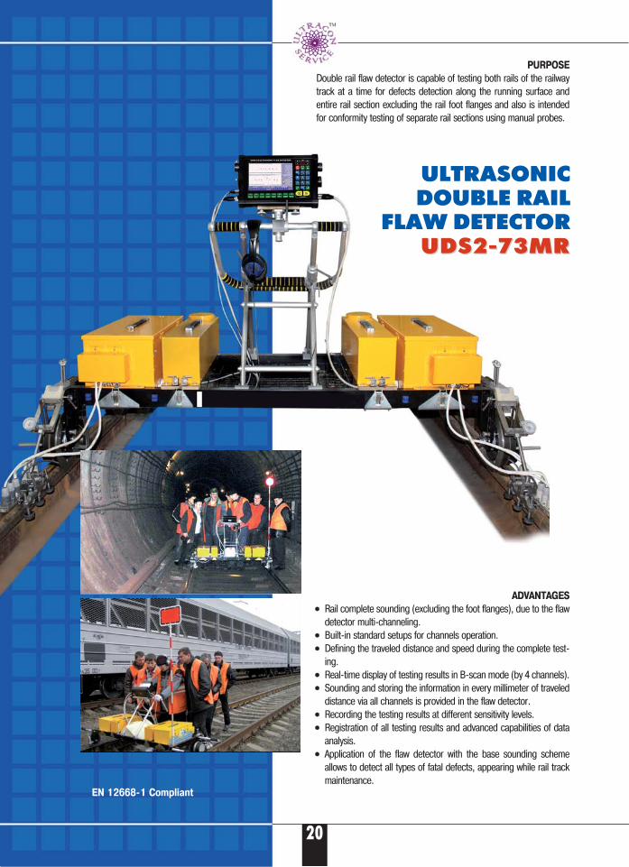
Double rail flaw detector is capable of testing both rails of the railwaytrack at a time for defects detection along the running surface andentire rail section excluding the rail foot flanges and also is intendedfor conformity testing of separate rail sections using manual probes.
ADVANTAGES
•• Rail complete sounding (excluding the foot flanges), due to the flawdetector multi�channeling.
•• Built�in standard setups for channels operation.•• Defining the traveled distance and speed during the complete test�
ing.•• Real�time display of testing results in B�scan mode (by 4 channels).•• Sounding and storing the information in every millimeter of traveled
distance via all channels is provided in the flaw detector.•• Recording the testing results at different sensitivity levels.•• Registration of all testing results and advanced capabilities of data
analysis.•• Application of the flaw detector with the base sounding scheme
allows to detect all types of fatal defects, appearing while rail trackmaintenance.
ULTRASONIC DOUBLE RAIL
FLAW DETECTORUDS2�73MRUDS2�73MR
20
EN 12668�1 Compliant
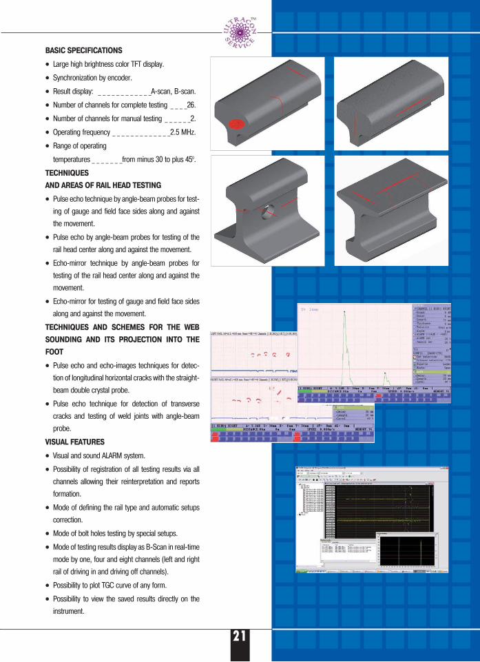
BASIC SPECIFICATIONS
•• Large high brightness color TFT display.
•• Synchronization by encoder.
•• Result display: _ _ _ _ _ _ _ _ _ _ _ _А�scan, B�scan.
•• Number of channels for complete testing _ _ _ _26.
•• Number of channels for manual testing _ _ _ _ _ _2.
•• Operating frequency _ _ _ _ _ _ _ _ _ _ _ _ _2.5 MHz.
•• Range of operating
temperatures _ _ _ _ _ _ _from minus 30 to plus 450.
TECHNIQUES
AND AREAS OF RAIL HEAD TESTING
•• Pulse echo technique by angle�beam probes for test�
ing of gauge and field face sides along and against
the movement.
•• Pulse echo by angle�beam probes for testing of the
rail head center along and against the movement.
•• Echo�mirror technique by angle�beam probes for
testing of the rail head center along and against the
movement.
•• Echo�mirror for testing of gauge and field face sides
along and against the movement.
TECHNIQUES AND SCHEMES FOR THE WEB
SOUNDING AND ITS PROJECTION INTO THE
FOOT
•• Pulse echo and echo�images techniques for detec�
tion of longitudinal horizontal cracks with the straight�
beam double crystal probe.
•• Pulse echo technique for detection of transverse
cracks and testing of weld joints with angle�beam
probe.
VISUAL FEATURES
•• Visual and sound ALARM system.
•• Possibility of registration of all testing results via all
channels allowing their reinterpretation and reports
formation.
•• Mode of defining the rail type and automatic setups
correction.
•• Mode of bolt holes testing by special setups.
•• Mode of testing results display as B�Scan in real�time
mode by one, four and eight channels (left and right
rail of driving in and driving off channels).
•• Possibility to plot TGC curve of any form.
•• Possibility to view the saved results directly on the
instrument.
21
CURRENT TASKS
•• Testing and measuring of the thickness ofparts and units made from metals and alloyswithout using coupling liquid.
•• Testing of unglued spots in couplings of thinaluminum plates.
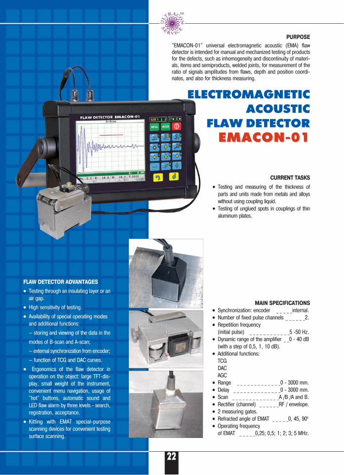
PURPOSE
"EМАCОN�01" universal electromagnetic acoustic (EMA) flawdetector is intended for manual and mechanized testing of productsfor the defects, such as inhomogeneity and discontinuity of materi�als, items and semiproducts, welded joints, for measurement of theratio of signals amplitudes from flaws, depth and position coordi�nates, and also for thickness measuring.
ELECTROMAGNETICACOUSTIC
FLAW DETECTOREMACON�01 EMACON�01
FLAW DETECTOR ADVANTAGES
•• Testing through an insulating layer or anair gap.
•• High sensitivity of testing.
•• Availability of special operating modesand additional functions:
— storing and viewing of the data in the
modes of B�scan and А�scan;
— external synchronization from encoder;
— function of TCG and DAC curves.
•• Ergonomics of the flaw detector inoperation on the object: large TFT�dis�play, small weight of the instrument,convenient menu navigation, usage of"hot" buttons, automatic sound andLED flaw alarm by three levels � search,registration, acceptance.
•• Kitting with EMAT special�purposescanning devices for convenient testingsurface scanning.
MAIN SPECIFICATIONS
•• Synchronization: encoder _ _ _ _ _internal.•• Number of fixed pulse channels _ _ _ _ _ _2.•• Repetition frequency
(initial pulse) _ _ _ _ _ _ _ _ _ _ _ _5 �50 Hz.•• Dynamic range of the amplifier _ _0 � 40 dB
(with a step of 0,5, 1, 10 dB).•• Additional functions:
TCGDACAGC
•• Range _ _ _ _ _ _ _ _ _ _ _ _ _0 � 3000 mm.•• Delay _ _ _ _ _ _ _ _ _ _ _ _ _ _0 � 3000 mm.•• Scan _ _ _ _ _ _ _ _ _ _ _ _ _ _А /B /А and B.•• Rectifier (channel) _ _ _ _ _ _RF / envelope. •• 2 measuring gates.•• Refracted angle of EMAT _ _ _ _ _0, 45, 900.
•• Operating frequency of EMAT _ _ _ _ _0,25; 0,5; 1; 2; 3; 5 МHz.
22
TDM�1 TDM�2
• Measurement results correction + +
according to probe's space position (00, 450, 900, 1350, 1800) (00, 900,1800)• Calibration option + +
• Statistic measurement mode + (from 3 to 99) + (3 and 5)• Automatic translation of hardness
to the ultimate tensile strength + —
• Battery discharge level control + +• Automatic alarm system of measured sound
value overrunning the user preset limits and visual visual• Measurement results storage + (2000) —
• Communication with PC through RS232 port; testing report generation option + —
• Non�stop operating time with full batteries,at least 1 hour 25 25
• Operating temperatures range — 10…+ 40 0С — 20…+ 50 0С• Case protection level IP40 IP65• Electronic unit dimensions 158 х 85 х 32 85 х 126 х 35• Unit weight, up to kg. 0,4 0,4
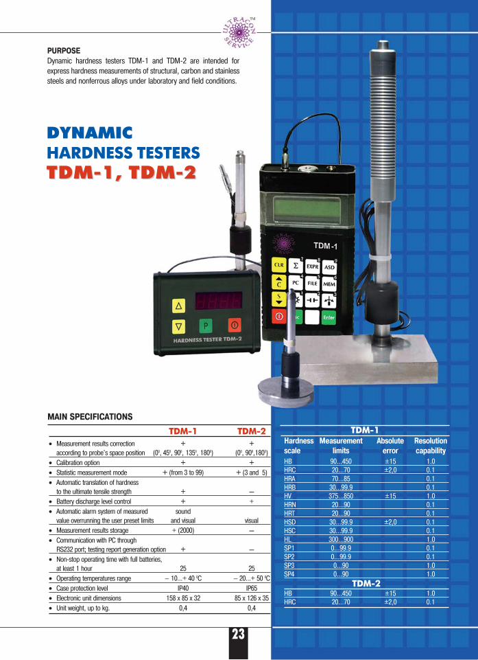
DYNAMIC HARDNESS TESTERS
TDM�1, TDM�2TDM�1, TDM�2
PURPOSE
Dynamic hardness testers TDM�1 and TDM�2 are intended forexpress hardness measurements of structural, carbon and stainlesssteels and nonferrous alloys under laboratory and field conditions.
MAIN SPECIFICATIONS
TDM�1Hardness Measurement Absolute Resolution
scale limits error capability
HB 90...450 ±15 1.0HRC 20...70 ±2,0 0.1HRA 70...85 0.1HRB 30...99.9 0.1HV 375...850 ±15 1.0HRN 20...90 0.1HRT 20...90 0.1HSD 30...99.9 ±2,0 0.1HSC 30...99.9 0.1HL 300...900 1.0SP1 0...99.9 0.1SP2 0...99.9 0.1SP3 0...90 1.0SP4 0...90 1.0
TDM�2HB 90...450 ±15 1.0HRC 20...70 ±2,0 0.1
23
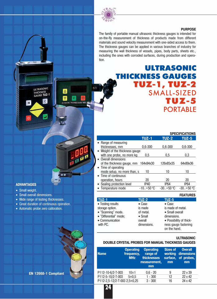
PURPOSE
The family of portable manual ultrasonic thickness gauges is intended foron�the�fly measurement of thickness of products made from differentmaterials and sound velocity measurement with one�sided access to them.The thickness gauges can be applied in various branches of industry formeasuring the wall thickness of vessels, pipes, body parts, sheets etc.,including the ones with corroded surfaces, during production and opera�tion.
ULTRASONIC THICKNESS GAUGES
TUZ�1, TUZ�2TUZ�1, TUZ�2SMALL�SIZED
T U Z � 5T U Z � 5PORTABLE
ADVANTAGES
• Small weight.• Small overall dimensions.• Wide range of testing thicknesses.• Great duration of continuous operation. • Automatic probe zero calibration.
Operating Operating Sizes of Overall
Name frequency, range of working dimensions
МHz thicknesses surface, of probes,
measurement, mm mm
mm
P112�10�6/2�Т�003 10±1 0,6 � 20 9 22 х 39P112�5�10/2�Т�003 5±0,5 1 � 300 12 22 х 42P112�2,5�12/2�Т�003 2,5±0,25 3 � 300 16 24 х 42
SPECIFICATIONS
ТUZ�1 ТUZ�2 ТUZ�5• Range of measuring
thicknesses, mm 0,6�300 0,6�300 0,6�300 • Weight of the thickness gauge
with one probe, no more kg 0,5 0,5 0,3 • Overall dimensions
of the thickness gauge, mm 164х84х30 126х85х35 64х89х36• Time of operating
mode setup, no more than, s 10 10 10• Time of continuous
operation, hours 20 20 20 • Sealing protection level IP40 IР64 IР64• Temperature mode �10..+50 0С �30..+50 0С �30..+50 0С
FEATURES
ТUZ�1 ТUZ�2 ТUZ�5
• Testing results • Case • Case storage option. is made is made of metal.• "Scanning" mode. of metal. • Small overall • "Differential" mode; • Small dimensions.• Communication overall • Possibility of thick�with PC. dimensions. ness gauge fastening
on the hand.
ULTRASONIC
DOUBLE CRYSTAL PROBES FOR MANUAL THICKNESS GAUGES
24
EN 12668�1 Compliant
25
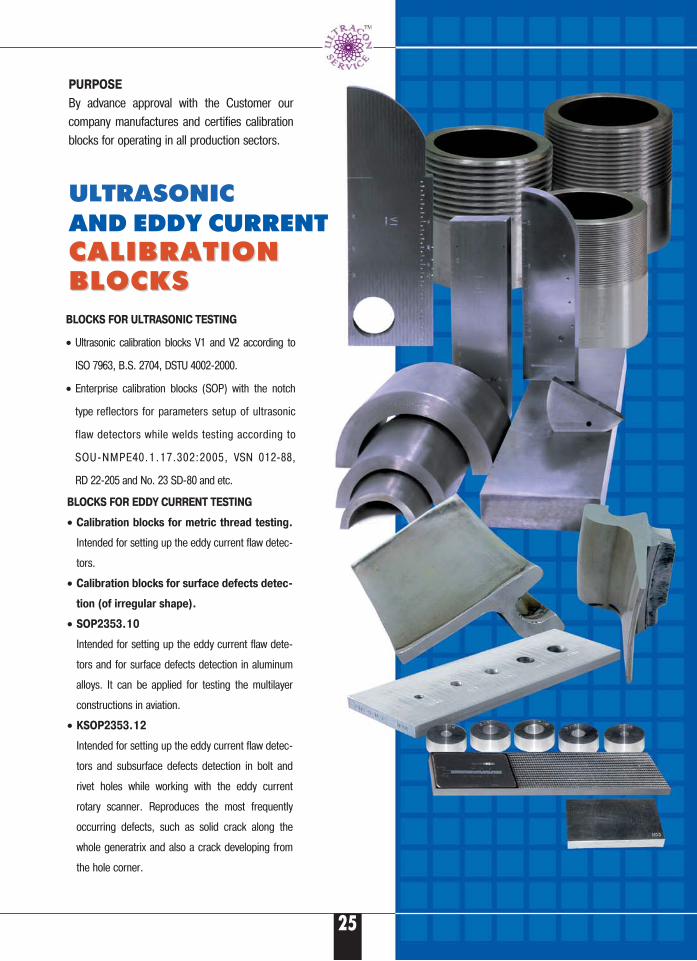
PURPOSE
By advance approval with the Customer ourcompany manufactures and certifies calibrationblocks for operating in all production sectors.
BLOCKS FOR EDDY CURRENT TESTING
• Calibration blocks for metric thread testing.
Intended for setting up the eddy current flaw detec�
tors.
• Calibration blocks for surface defects detec�
tion (of irregular shape).
• SOP2353.10
Intended for setting up the eddy current flaw dete�
tors and for surface defects detection in aluminum
alloys. It can be applied for testing the multilayer
constructions in aviation.
• KSOP2353.12
Intended for setting up the eddy current flaw detec�
tors and subsurface defects detection in bolt and
rivet holes while working with the eddy current
rotary scanner. Reproduces the most frequently
occurring defects, such as solid crack along the
whole generatrix and also a crack developing from
the hole corner.
ULTRASONICAND EDDY CURRENT CALIBRATIONCALIBRATIONBLOCKSBLOCKS
BLOCKS FOR ULTRASONIC TESTING
• Ultrasonic calibration blocks V1 and V2 according to
ISO 7963, B.S. 2704, DSTU 4002�2000.
• Enterprise calibration blocks (SOP) with the notch
type reflectors for parameters setup of ultrasonic
flaw detectors while welds testing according to
SOU�NMPE40.1.17.302:2005, VSN 012�88,
RD 22�205 and No. 23 SD�80 and etc.
UKRAINIAN SCIENTIFIC RESEARCH INSTITUTE FOR NON�DESTRUCTIVE TESTING
8, Naberezhno�Lugova Str.,Kiev, Ukraine, 04071
Tel./Fax:+380 44 531�37�26(27)E�mail: [email protected]
www.ndt.com.ua
НДІ
27
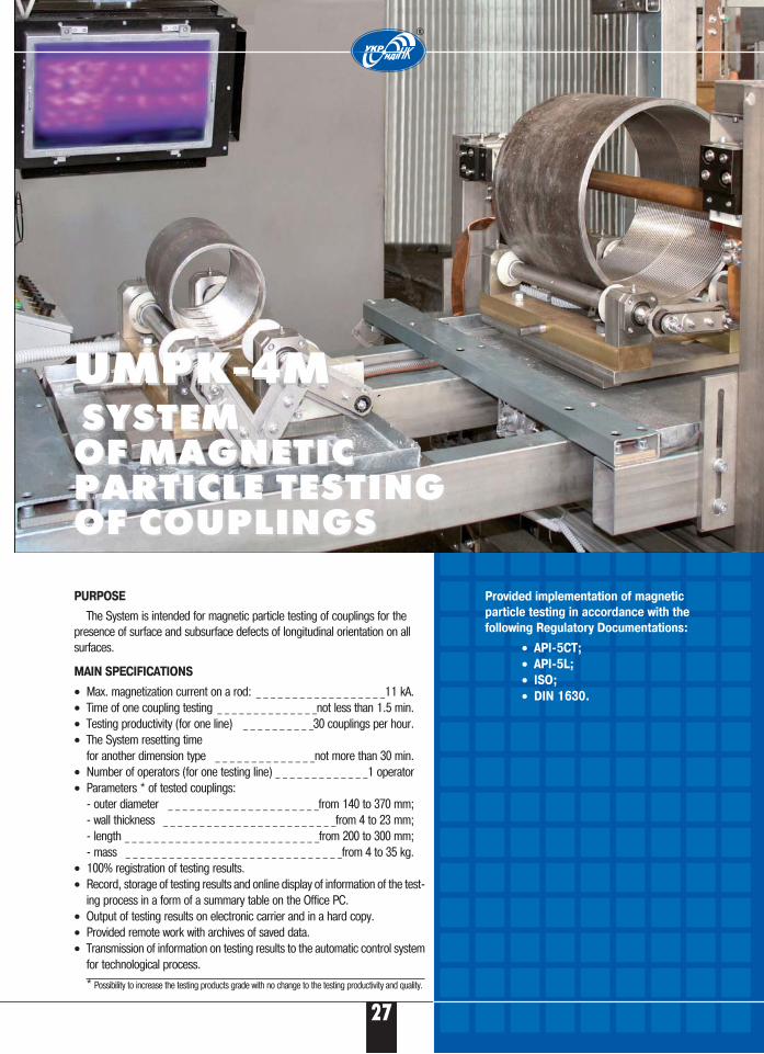
PURPOSE
The System is intended for magnetic particle testing of couplings for thepresence of surface and subsurface defects of longitudinal orientation on allsurfaces.
MAIN SPECIFICATIONS
• Max. magnetization current on a rod: _ _ _ _ _ _ _ _ _ _ _ _ _ _ _ _ _ _11 kA.• Time of one coupling testing _ _ _ _ _ _ _ _ _ _ _ _ _ _not less than 1.5 min.• Testing productivity (for one line) _ _ _ _ _ _ _ _ _ _30 couplings per hour.• The System resetting time
for another dimension type _ _ _ _ _ _ _ _ _ _ _ _ _ _not more than 30 min.• Number of operators (for one testing line) _ _ _ _ _ _ _ _ _ _ _ _ _1 operator• Parameters * of tested couplings:
� outer diameter _ _ _ _ _ _ _ _ _ _ _ _ _ _ _ _ _ _ _ _ _from 140 to 370 mm;� wall thickness _ _ _ _ _ _ _ _ _ _ _ _ _ _ _ _ _ _ _ _ _ _ _ _from 4 to 23 mm;� length _ _ _ _ _ _ _ _ _ _ _ _ _ _ _ _ _ _ _ _ _ _ _ _ _ _ _from 200 to 300 mm;� mass _ _ _ _ _ _ _ _ _ _ _ _ _ _ _ _ _ _ _ _ _ _ _ _ _ _ _ _ _ _from 4 to 35 kg.
• 100% registration of testing results.• Record, storage of testing results and online display of information of the test�
ing process in a form of a summary table on the Office PC.• Output of testing results on electronic carrier and in a hard copy.• Provided remote work with archives of saved data.• Transmission of information on testing results to the automatic control system
for technological process.
* Possibility to increase the testing products grade with no change to the testing productivity and quality.
UMPK�4MUMPK�4MSYSTEM SYSTEM
OF MAGNETIC OF MAGNETIC PARTICLE TESTING PARTICLE TESTING OF COUPLINGSOF COUPLINGS
Provided implementation of magnetic
particle testing in accordance with the
following Regulatory Documentations:
• API�5CT;
• API�5L;
• ISO;
• DIN 1630.
®
28
®
MAIN SPECIFICATIONS
• Testing time, no more than _ _ _ _ _ _ _ _ _ _ _ _ _ _ _ _ _6 min.• In�line display of testing results.• Saving the complete testing results in electronic format with the
possibility of further review, analysis and creation of statisticalreports.
CONSIDERING THE CUSTOMER`S REQUIREMENTS THE
SYSTEM CAN IMPLEMENT THE FOLLOWING FEATURES AS:
• Carrying out a complex 100% eddy current testing of axle surface.• Changing the testing scheme by using additional probes and
sounding schemes.• Improving the couplant supply system.• Introducing the customer`s requirements into the System software.
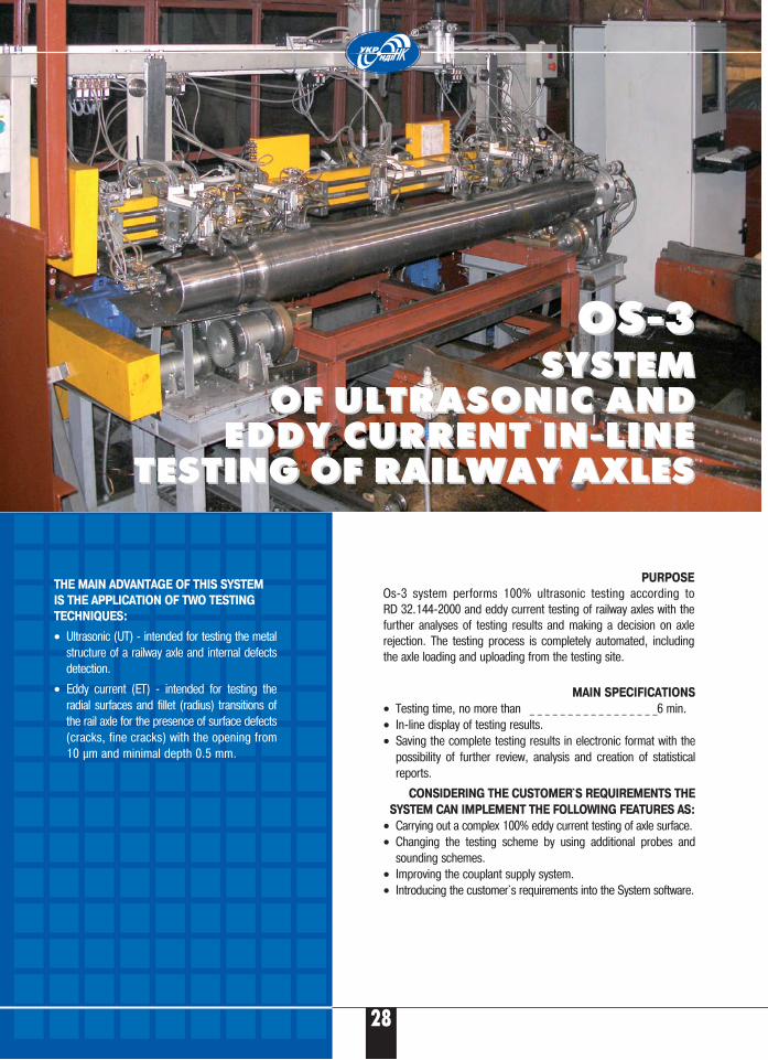
OS�3OS�3SYSTEM SYSTEM
OF OF ULTRASONIC AND ULTRASONIC AND EDDY CURRENT IN�LINE EDDY CURRENT IN�LINE
TESTING OF RAILWAY AXLES TESTING OF RAILWAY AXLES
THE MAIN ADVANTAGE OF THIS SYSTEM
IS THE APPLICATION OF TWO TESTING
TECHNIQUES:
• Ultrasonic (UT) � intended for testing the metalstructure of a railway axle and internal defectsdetection.
• Eddy current (ET) � intended for testing theradial surfaces and fillet (radius) transitions ofthe rail axle for the presence of surface defects(cracks, fine cracks) with the opening from10 μm and minimal depth 0.5 mm.
PURPOSE
Os�3 system performs 100% ultrasonic testing according toRD 32.144�2000 and eddy current testing of railway axles with thefurther analyses of testing results and making a decision on axlerejection. The testing process is completely automated, includingthe axle loading and uploading from the testing site.
29
®
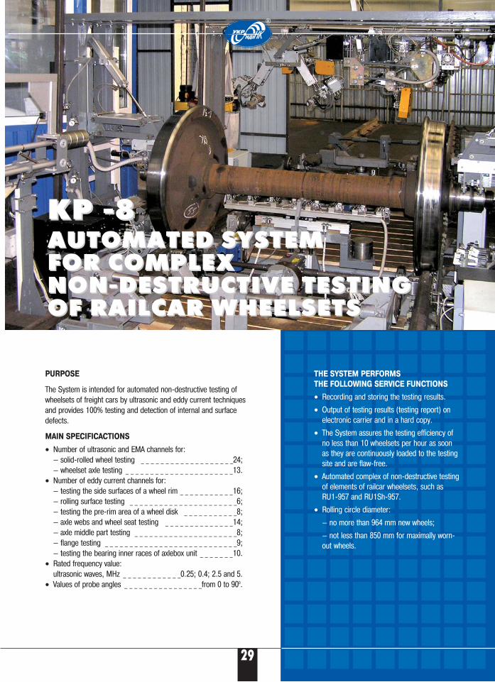
THE SYSTEM PERFORMS
THE FOLLOWING SERVICE FUNCTIONS
• Recording and storing the testing results.
• Output of testing results (testing report) onelectronic carrier and in a hard copy.
• The System assures the testing efficiency ofno less than 10 wheelsets per hour as soonas they are continuously loaded to the testingsite and are flaw�free.
• Automated complex of non�destructive testingof elements of railcar wheelsets, such asRU1�957 and RU1Sh�957.
• Rolling circle diameter:
— no more than 964 mm new wheels;
— not less than 850 mm for maximally worn�out wheels.
KP �8KP �8AUTOMATED SYSTEM AUTOMATED SYSTEM FOR COMPLEX FOR COMPLEX NON�DESTRUCTIVE TESTINGNON�DESTRUCTIVE TESTINGOF RAILCAR WHEELSETSOF RAILCAR WHEELSETS
PURPOSE
The System is intended for automated non�destructive testing ofwheelsets of freight cars by ultrasonic and eddy current techniquesand provides 100% testing and detection of internal and surfacedefects.
MAIN SPECIFICACTIONS
• Number of ultrasonic and EMA channels for:— solid�rolled wheel testing _ _ _ _ _ _ _ _ _ _ _ _ _ _ _ _ _ _ _24;— wheelset axle testing _ _ _ _ _ _ _ _ _ _ _ _ _ _ _ _ _ _ _ _ _ _13.
• Number of eddy current channels for:— testing the side surfaces of a wheel rim _ _ _ _ _ _ _ _ _ _ _16;— rolling surface testing _ _ _ _ _ _ _ _ _ _ _ _ _ _ _ _ _ _ _ _ _ _6;— testing the pre�rim area of a wheel disk _ _ _ _ _ _ _ _ _ _ _8;— axle webs and wheel seat testing _ _ _ _ _ _ _ _ _ _ _ _ _ _14;— axle middle part testing _ _ _ _ _ _ _ _ _ _ _ _ _ _ _ _ _ _ _ _ _8;— flange testing _ _ _ _ _ _ _ _ _ _ _ _ _ _ _ _ _ _ _ _ _ _ _ _ _ _ _9;— testing the bearing inner races of axlebox unit _ _ _ _ _ _ _10.
• Rated frequency value:ultrasonic waves, MHz _ _ _ _ _ _ _ _ _ _ _ _0.25; 0.4; 2.5 and 5.
• Values of probe angles _ _ _ _ _ _ _ _ _ _ _ _ _ _ _ _from 0 to 900.
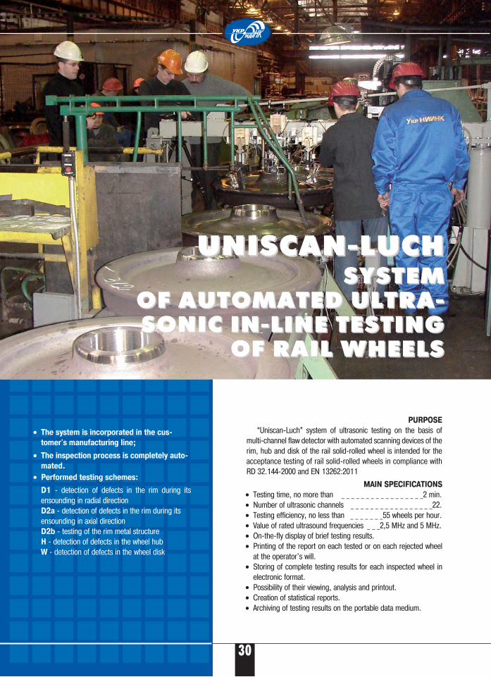
MAIN SPECIFICATIONS
• Testing time, no more than _ _ _ _ _ _ _ _ _ _ _ _ _ _ _ _ _2 min.• Number of ultrasonic channels _ _ _ _ _ _ _ _ _ _ _ _ _ _ _ _ _22.• Testing efficiency, no less than _ _ _ _ _ _ _55 wheels per hour.• Value of rated ultrasound frequencies _ _ _2,5 МHz and 5 МHz.• On�the�fly display of brief testing results.• Printing of the report on each tested or on each rejected wheel
at the operator's will.• Storing of complete testing results for each inspected wheel in
electronic format.• Possibility of their viewing, analysis and printout. • Creation of statistical reports. • Archiving of testing results on the portable data medium.
UNISCAN�LUCH UNISCAN�LUCH SYSTEM SYSTEM
OF AUTOMATED ULTRAOF AUTOMATED ULTRA��SONIC IN�LINE TESTING SONIC IN�LINE TESTING
OF RAIL WHEELSOF RAIL WHEELS
PURPOSE
“Uniscan�Luch” system of ultrasonic testing on the basis ofmulti�channel flaw detector with automated scanning devices of therim, hub and disk of the rail solid�rolled wheel is intended for theacceptance testing of rail solid�rolled wheels in compliance withRD 32.144�2000 and EN 13262:2011
• The system is incorporated in the cus�
tomer's manufacturing line;
• The inspection process is completely auto�
mated.
• Performed testing schemes:
D1 � detection of defects in the rim during itsensounding in radial direction D2a � detection of defects in the rim during itsensounding in axial directionD2b � testing of the rim metal structure H � detection of defects in the wheel hubW � detection of defects in the wheel disk
30
®
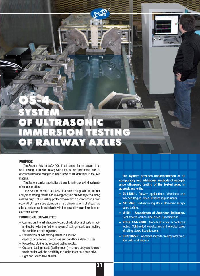
PURPOSE
The System Uniscan�LuCH "Os�4" is intended for immersion ultra�sonic testing of axles of railway wheelsets for the presence of internaldiscontinuities and changes in attenuation of UT vibrations in the axlematerial.
The System can be applied for ultrasonic testing of cylindrical partsof various profiles.
The System provides a 100% ultrasonic testing with the furtheranalysis of testing results and making decision on axle rejection alongwith the output of full testing protocol to electronic carrier and in a hardcopy. All UT results are stored on a hard drive in a form of B�scan viaall channels on each tested axle with the possibility to archive them onelectronic carrier.
FUNCTIONAL CAPABILITIES
• Carrying out the full ultrasonic testing of axle structural parts in radi�al direction with the further analysis of testing results and makingthe decision an axle rejection.
• Presentation of axle testing results in a matrix:depth of occurrence, coordinates and conditional defects sizes.
• Recording, storing the received testing results.• Output of testing results (testing report) in a hard copy and to elec�
tronic carrier with the possibility to archive them on a hard drive.• Light and Sound flaw ALARM.
The System provides implementation of all
compulsory and additional methods of accept�
ance ultrasonic testing of the tested axle, in
accordance with:
• EN13261. Railway applications. Wheelsets andtwo�axle bogies. Axles. Product requirements
• ISO 5948. Railway rolling stock. Ultrasonic accep�tance testing.
• M101 � Association of American Railroads.
Heat�treated carbon steel axles. Specifications.
• RD32.144�2000. Non�destructive acceptancetesting. Solid�rolled wheels, rims and wheelset axlesof rolling stock. Specifications.
• BN 918275 � Wheelset shafts for rolling stock trac�tion units and wagons.
OS�4OS�4SYSTEM SYSTEM OF ULTRASONIC OF ULTRASONIC IMMERSION TESTING IMMERSION TESTING OF RAILWAY AXLESOF RAILWAY AXLES
31
®
32
Б
PSH�10PSH�10AUTOMATED ULTRASONICAUTOMATED ULTRASONIC
SYSTEM OF LONGITUDINALSYSTEM OF LONGITUDINALWELDED JOINTS TESTING WELDED JOINTS TESTING
OF MEAN AND LARGE OF MEAN AND LARGE DIAMETER PIPESDIAMETER PIPES
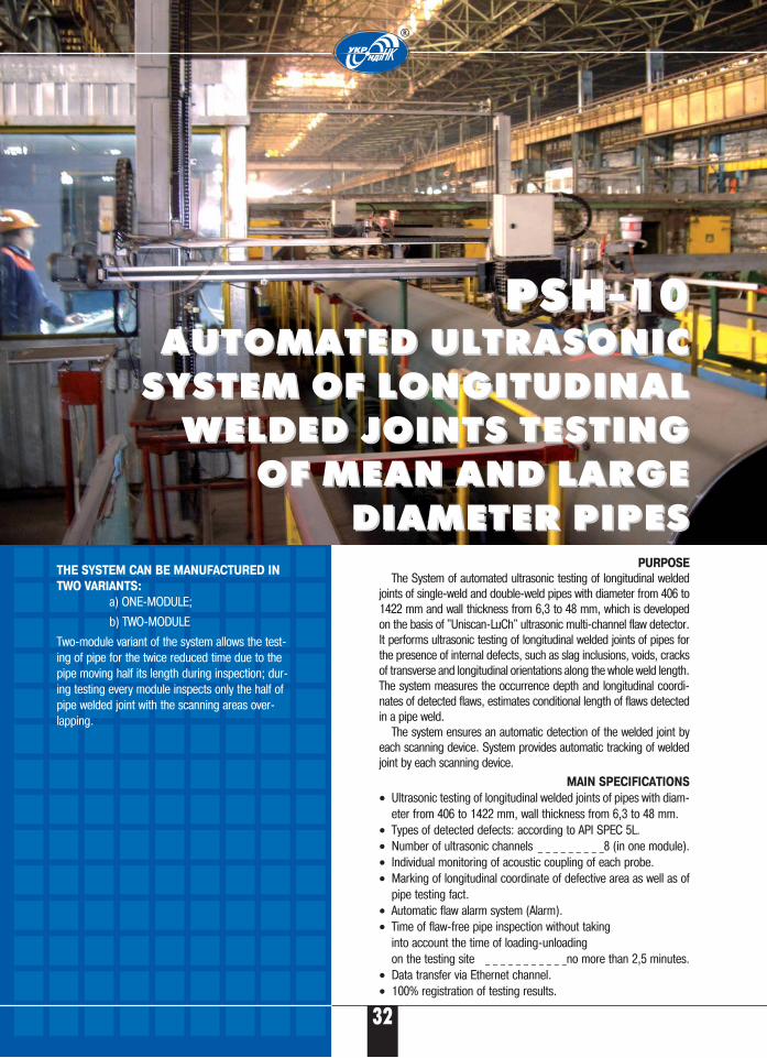
PURPOSE
The System of automated ultrasonic testing of longitudinal weldedjoints of single�weld and double�weld pipes with diameter from 406 to1422 mm and wall thickness from 6,3 to 48 mm, which is developedon the basis of "Uniscan�LuCh" ultrasonic multi�channel flaw detector.It performs ultrasonic testing of longitudinal welded joints of pipes forthe presence of internal defects, such as slag inclusions, voids, cracksof transverse and longitudinal orientations along the whole weld length.The system measures the occurrence depth and longitudinal coordi�nates of detected flaws, estimates conditional length of flaws detectedin a pipe weld.
The system ensures an automatic detection of the welded joint byeach scanning device. System provides automatic tracking of weldedjoint by each scanning device.
MAIN SPECIFICATIONS
• Ultrasonic testing of longitudinal welded joints of pipes with diam�eter from 406 to 1422 mm, wall thickness from 6,3 to 48 mm.
• Types of detected defects: according to API SPEC 5L.• Number of ultrasonic channels _ _ _ _ _ _ _ _ _8 (in one module).• Individual monitoring of acoustic coupling of each probe.• Marking of longitudinal coordinate of defective area as well as of
pipe testing fact.• Automatic flaw alarm system (Alarm).• Time of flaw�free pipe inspection without taking
into account the time of loading�unloading on the testing site _ _ _ _ _ _ _ _ _ _ _no more than 2,5 minutes.
• Data transfer via Ethernet channel.• 100% registration of testing results.
THE SYSTEM CAN BE MANUFACTURED IN
TWO VARIANTS:
a) ONE�MODULE;
b) TWO�MODULE
Two�module variant of the system allows the test�ing of pipe for the twice reduced time due to thepipe moving half its length during inspection; dur�ing testing every module inspects only the half ofpipe welded joint with the scanning areas over�lapping.
®
33
Б
®
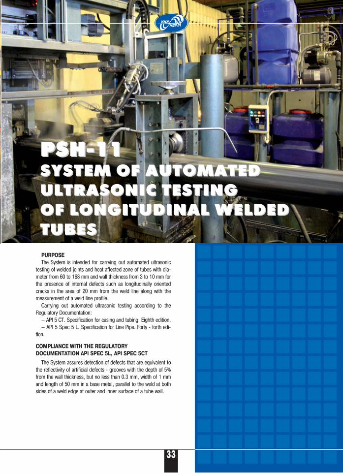
PURPOSE
The System is intended for carrying out automated ultrasonictesting of welded joints and heat affected zone of tubes with dia�meter from 60 to 168 mm and wall thickness from 3 to 10 mm forthe presence of internal defects such as longitudinally orientedcracks in the area of 20 mm from the weld line along with themeasurement of a weld line profile.
Carrying out automated ultrasonic testing according to theRegulatory Documentation:
— API 5 CT. Specification for casing and tubing. Eighth edition.— API 5 Spec 5 L. Specification for Line Pipe. Forty � forth edi�
tion.
PPSSHH��1111 PPSSHH��1111 SYSTEM OF AUTOMATED SYSTEM OF AUTOMATED ULTRASONIC TESTING ULTRASONIC TESTING OF LONGITUDINAL WELDEDOF LONGITUDINAL WELDEDTUBESTUBES
COMPLIANCE WITH THE REGULATORY
DOCUMENTATION API SPEC 5L, API SPEC 5CT
The System assures detection of defects that are equivalent tothe reflectivity of artificial defects � grooves with the depth of 5%from the wall thickness, but no less than 0.3 mm, width of 1 mmand length of 50 mm in a base metal, parallel to the weld at bothsides of a weld edge at outer and inner surface of a tube wall.
34
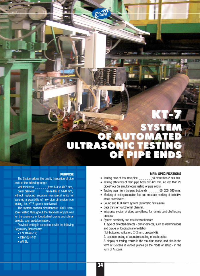
MAIN SPECIFICATIONS
• Testing time of flaw�free pipe _ _ _ _ _ _ _no more than 2 minutes.• Testing efficiency of main pipe body d=1422 mm, no less than 20
pipes/hour (in simultaneous testing of pipe ends).• Testing area (from the pipe butt end) _ _ _ _ _ _60, 200, 540 mm.• Marking of testing execution fact and separate marking of defective
areas coordinates.• Sound and LED alarm system (automatic flaw alarm).• Data transfer via Ethernet channel.• Integrated system of video surveillance for remote control of testing
process.• System sensitivity and results visualization:
1. type of detected defects � planar defects, such as delaminationsand cracks of longitudinal orientation (flat�bottomed reflectors ∅ 3 mm, groove N5);2. separate testing of acoustic coupling of each probe;3. display of testing results in the real�time mode, and also in theform of B�scans in various planes (in the mode of setup � in theform of А�scan).
KT�7KT�7SYSTEM SYSTEM
OF AUTOMATEDOF AUTOMATEDULTRASONIC TESTINGULTRASONIC TESTING
OF PIPE ENDSOF PIPE ENDS
PURPOSE
The System allows the quality inspection of pipeends of the following range:
wall thickness _ _ _ _ _ _ _from 6.3 to 40.7 mm, outer diameter _ _ _ _ _ _from 406 to 1420 mm,
without replacing separate mechanical units forassuring a possibility of new pipe dimension�typetesting, i.е. KТ�7 system is universal.
The system enables simultaneous 100% ultra�sonic testing throughout the thickness of pipe wallfor the presence of longitudinal cracks and planardefects, such as delamination.
Provided testing in accordance with the follovingRegulatory Documents:
• EN 10246�17; • DNV�03�F101; • API 5L.
®
35
®
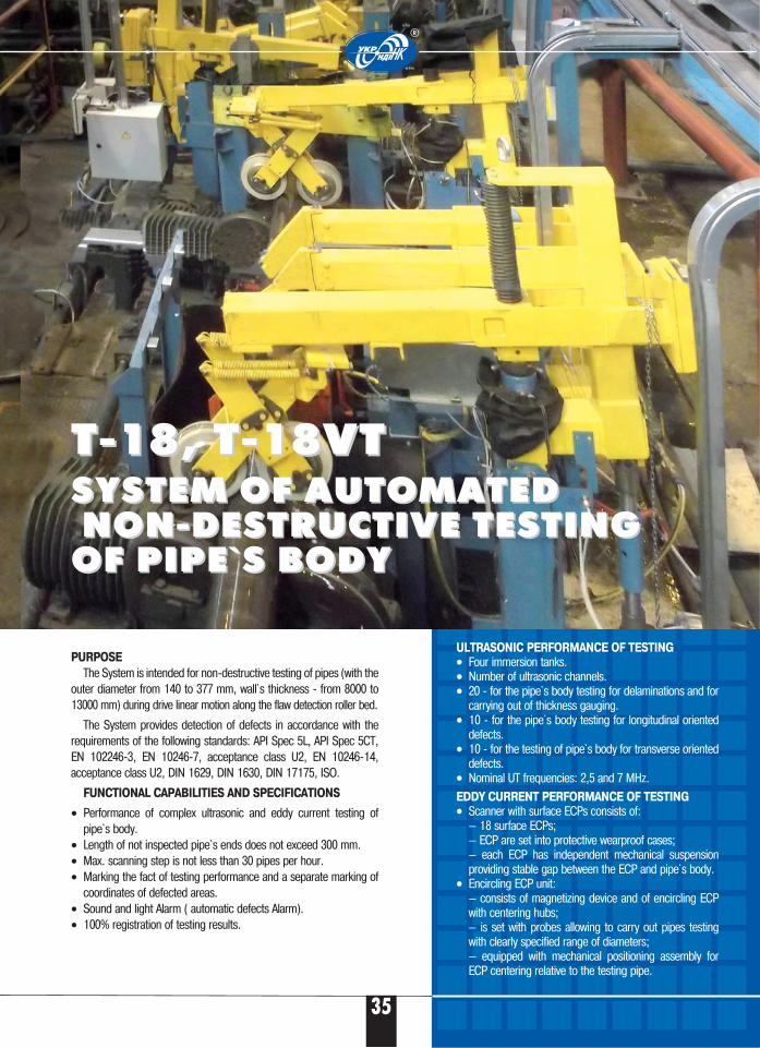
PURPOSE
The System is intended for non�destructive testing of pipes (with theouter diameter from 140 to 377 mm, wall`s thickness � from 8000 to13000 mm) during drive linear motion along the flaw detection roller bed.
The System provides detection of defects in accordance with therequirements of the following standards: API Spec 5L, API Spec 5CT,EN 102246�3, EN 10246�7, acceptance class U2, EN 10246�14,acceptance class U2, DIN 1629, DIN 1630, DIN 17175, ISO.
FUNCTIONAL CAPABILITIES AND SPECIFICATIONS
• Performance of complex ultrasonic and eddy current testing ofpipe`s body.
• Length of not inspected pipe`s ends does not exceed 300 mm.• Max. scanning step is not less than 30 pipes per hour.• Marking the fact of testing performance and a separate marking of
coordinates of defected areas. • Sound and light Alarm ( automatic defects Alarm).• 100% registration of testing results.
ULTRASONIC PERFORMANCE OF TESTING•• Four immersion tanks.•• Number of ultrasonic channels.•• 20 � for the pipe`s body testing for delaminations and for
carrying out of thickness gauging.•• 10 � for the pipe`s body testing for longitudinal oriented
defects.•• 10 � for the testing of pipe`s body for transverse oriented
defects.•• Nominal UT frequencies: 2,5 and 7 MHz.
EDDY CURRENT PERFORMANCE OF TESTING•• Scanner with surface ECPs consists of:
— 18 surface ECPs;— ECP are set into protective wearproof cases;— each ECP has independent mechanical suspensionproviding stable gap between the ECP and pipe`s body.
•• Encircling ECP unit:— consists of magnetizing device and of encircling ECPwith centering hubs;— is set with probes allowing to carry out pipes testingwith clearly specified range of diameters;— equipped with mechanical positioning assembly forECP centering relative to the testing pipe.
T�18, T�18VTT�18, T�18VTSYSTEM OF AUTOMATEDSYSTEM OF AUTOMATEDNON�DESTRUCTIVE TESTINGNON�DESTRUCTIVE TESTING
OF PIPE`S BODY OF PIPE`S BODY
MAIN SPECIFICATIONS
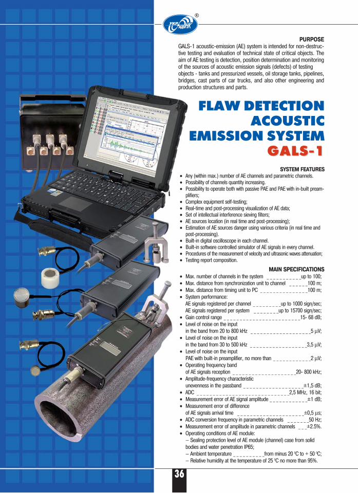
• Max. number of channels in the system _ _ _ _ _ _ _ _ _ _ _up to 100;• Max. distance from synchronization unit to channel _ _ _ _ _ _100 m;• Max. distance from timing unit to PC _ _ _ _ _ _ _ _ _ _ _ _ _ _ _100 m;• System performance:
AE signals registered per channel _ _ _ _ _ _ _ _ _up to 1000 sign/sec;AE signals registered per system _ _ _ _ _ _ _ _up to 15700 sign/sec;
• Gain control range _ _ _ _ _ _ _ _ _ _ _ _ _ _ _ _ _ _ _ _ _ _ _ _15� 68 dB;• Level of noise on the input
in the band from 20 to 800 kHz _ _ _ _ _ _ _ _ _ _ _ _ _ _ _ _ _ _ _5 μV;• Level of noise on the input
in the band from 30 to 500 kHz _ _ _ _ _ _ _ _ _ _ _ _ _ _ _ _ _ _3,5 μV;• Level of noise on the input
PAE with built�in preamplifier, no more than _ _ _ _ _ _ _ _ _ _ _ _2 μV;• Operating frequency band
of AE signals reception _ _ _ _ _ _ _ _ _ _ _ _ _ _ _ _ _ _ _ _20� 800 kHz;• Amplitude�frequency characteristic
unevenness in the passband _ _ _ _ _ _ _ _ _ _ _ _ _ _ _ _ _ _ _±1,5 dB;• ADC _ _ _ _ _ _ _ _ _ _ _ _ _ _ _ _ _ _ _ _ _ _ _ _ _ _ _ _ _2,5 МHz, 16 bit;• Measurement error of AE signal amplitude _ _ _ _ _ _ _ _ _ _ _ _±1 dB;• Measurement error of difference
of AE signals arrival time _ _ _ _ _ _ _ _ _ _ _ _ _ _ _ _ _ _ _ _ _±0,5 μs;• ADC conversion frequency in parametric channels _ _ _ _ _ _ _50 Hz;• Measurement error of amplitude in parametric channels _ _ _±2.5%.• Operating conditions of AE module:
— Sealing protection level of AE module (channel) case from solidbodies and water penetration IP65;— Ambient temperature _ _ _ _ _ _ _ _ _ _from minus 20 0С to + 50 0С;— Relative humidity at the temperature of 25 0С no more than 95%.
SYSTEM FEATURES
• Any (within max.) number of AE channels and parametric channels.• Possibility of channels quantity increasing.• Possibility to operate both with passive PAE and PAE with in�built pream�
plifiers;• Complex equipment self�testing;• Real�time and post�processing visualization of AE data;• Set of intellectual interference sieving filters;• AE sources location (in real time and post�processing);• Estimation of AE sources danger using various criteria (in real time and
post�processing).• Built�in digital oscilloscope in each channel.• Built�in software controlled simulator of AE signals in every channel.• Procedures of the measurement of velocity and ultrasonic waves attenuation;• Testing report composition.
PURPOSE
GALS�1 acoustic�emission (AE) system is intended for non�destruc�tive testing and evaluation of technical state of critical objects. Theaim of AE testing is detection, position determination and monitoringof the sources of acoustic emission signals (defects) of testingobjects � tanks and pressurized vessels, oil storage tanks, pipelines,bridges, cast parts of car trucks, and also other engineering andproduction structures and parts.
FLAW DETECTION ACOUSTIC
EMISSION SYSTEMGALS�1GALS�1
®
36
Б
37
Б
UKTLUKTLMECHANIZED MECHANIZED SYSTEM SYSTEM OF ULTRASONIC OF ULTRASONIC TESTING OF STEEL STRAP TESTING OF STEEL STRAP
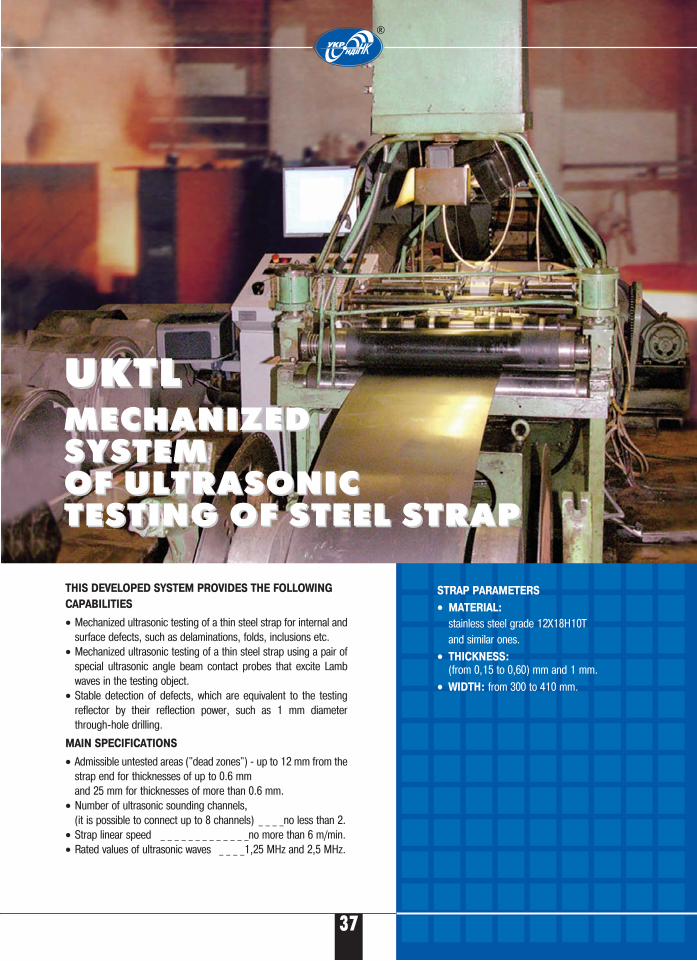
THIS DEVELOPED SYSTEM PROVIDES THE FOLLOWING
CAPABILITIES
• Mechanized ultrasonic testing of a thin steel strap for internal andsurface defects, such as delaminations, folds, inclusions etc.
• Mechanized ultrasonic testing of a thin steel strap using a pair ofspecial ultrasonic angle beam contact probes that excite Lambwaves in the testing object.
• Stable detection of defects, which are equivalent to the testingreflector by their reflection power, such as 1 mm diameterthrough�hole drilling.
MAIN SPECIFICATIONS
• Admissible untested areas ("dead zones") � up to 12 mm from thestrap end for thicknesses of up to 0.6 mm and 25 mm for thicknesses of more than 0.6 mm.
• Number of ultrasonic sounding channels, (it is possible to connect up to 8 channels) _ _ _ _no less than 2.
• Strap linear speed _ _ _ _ _ _ _ _ _ _ _ _ _no more than 6 m/min.• Rated values of ultrasonic waves _ _ _ _1,25 MHz and 2,5 MHz.
STRAP PARAMETERS
•• MATERIAL:
stainless steel grade 12Х18Н10Т and similar ones.
•• THICKNESS:
(from 0,15 to 0,60) mm and 1 mm.•• WIDTH: from 300 to 410 mm.
®
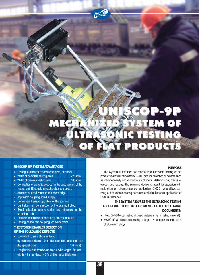
PURPOSE
The System is intended for mechanized ultrasonic testing of flatproducts with wall thickness of 7�100 mm for detection of defects suchas inhomogeneity and discontinuity of metal, delamination, cracks ofvarious orientations. The scanning device is meant for operation withmulti�channel instruments of our production (OKO�3), what allows car�rying out of various testing schemes and simultaneous application ofup to 32 channels.
THE SYSTEM ASSURES THE ULTRASONIC TESTING
ACCORDING TO THE REQUIREMENTS OF THE FOLLOWING
DOCUMENTS:
• PNAE G�7�014�89 Testing of basic materials (semifinished material).• MK 52�40�81 Ultrasonic testing of large�size workpieces and plates
of aluminum alloys.
38
UNISCOP�9PUNISCOP�9PMECHANIZED SYSTEM OFMECHANIZED SYSTEM OF
ULTRASONIC TESTING ULTRASONIC TESTING OF FLAT PRODUCTS OF FLAT PRODUCTS
UNISCOP�9P SYSTEM ADVANTAGES
• Testing in different modes (complete, discrete).• Width of complete testing area _ _ _ _ _ _ _ _ _225 mm.• Width of discrete testing area _ _ _ _ _ _ _ _ _405 mm.• Connection of up to 32 probes (in the base version of the
instrument 18 double crystal probes are used).• Absence of dead zones at the sheet edge.• Adjustable coupling liquid supply.• Convenient transport position of the scanner.• Light aluminum construction of the bearing trolley.• Synchronization from encoder and reference to the
scanning path.• Possible installation of additional probes modules.• Testing of acoustic coupling for every probe.
®
THE SYSTEM ENABLES DETECTION
OF THE FOLLOWING DEFECTS
• Equivalent to an artificial reflector by its characteristics � 3mm diameter flat�bottomed hole(by special order _ _ _ _ _ _ _ _ _ _ _ _ _ _ _ _1.6 mm).
• Longitudinal and transverse cracks with length 50 mm, width � 1 mm, depth � 5% of the metal thickness.
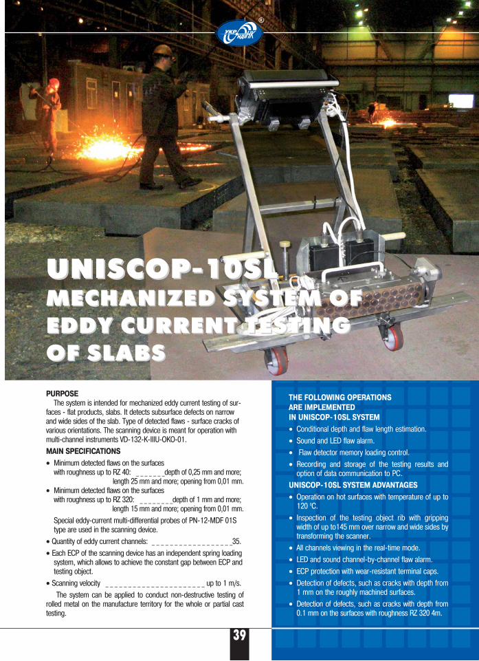
39
®
UNISCOP�10SLUNISCOP�10SLMECHANIZED SYSTEM OFMECHANIZED SYSTEM OFEDDY CURRENT TESTING EDDY CURRENT TESTING OF SLABS OF SLABS
PURPOSE
The system is intended for mechanized eddy current testing of sur�faces � flat products, slabs. It detects subsurface defects on narrowand wide sides of the slab. Type of detected flaws � surface cracks ofvarious orientations. The scanning device is meant for operation withmulti�channel instruments VD�132�K�IIIU�OKO�01.
MAIN SPECIFICATIONS
• Minimum detected flaws on the surfaces with roughness up to RZ 40: _ _ _ _ _ _ _depth of 0,25 mm and more;
length 25 mm and more; opening from 0,01 mm.• Minimum detected flaws on the surfaces
with roughness up to RZ 320: _ _ _ _ _ _ _ _depth of 1 mm and more; length 15 mm and more; opening from 0,01 mm.
Special eddy�current multi�differential probes of PN�12�MDF 01Stype are used in the scanning device.
• Quantity of eddy current channels: _ _ _ _ _ _ _ _ _ _ _ _ _ _ _ _ _ _35.
• Each ECP of the scanning device has an independent spring loadingsystem, which allows to achieve the constant gap between ECP andtesting object.
• Scanning velocity _ _ _ _ _ _ _ _ _ _ _ _ _ _ _ _ _ _ _ _ _ _ up to 1 m/s.
The system can be applied to conduct non�destructive testing ofrolled metal on the manufacture territory for the whole or partial casttesting.
THE FOLLOWING OPERATIONS
ARE IMPLEMENTED
IN UNISCOP�10SL SYSTEM
• Conditional depth and flaw length estimation.
• Sound and LED flaw alarm.
• Flaw detector memory loading control.
• Recording and storage of the testing results andoption of data communication to PC.
UNISCOP�10SL SYSTEM ADVANTAGES
• Operation on hot surfaces with temperature of up to120 0С.
• Inspection of the testing object rib with grippingwidth of up to145 mm over narrow and wide sides bytransforming the scanner.
• All channels viewing in the real�time mode.
• LED and sound channel�by�channel flaw alarm.
• ECP protection with wear�resistant terminal caps.
• Detection of defects, such as cracks with depth from1 mm on the roughly machined surfaces.
• Detection of defects, such as cracks with depth from0.1 mm on the surfaces with roughness RZ 320 4m.
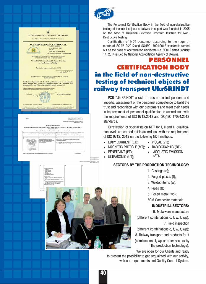
The Personnel Certification Body in the field of non�destructivetesting of technical objects of railway transport was founded in 2005on the base of Ukrainian Scientific Research Institute for Non�Destructive Testing.
Certification of NDT personnel according to the require�ments of ISO 9712:2012 and ISO/IEC 17024:2012 standard is carriedout on the basis of Accreditation Certificate No. 6O012 dated January14, 2014 issued by National Accreditation Agency of Ukraine.
®
40
Б
PERSONNEL CERTIFICATION BODY
in the field of non�destructivetesting of technical objects of
railway transport UkrSRINDTPCB "UkrSRINDT" assists to ensure an independent and
impartial assessment of the personnel competence to build thetrust and recognition with our customers and meet their needsin improvement of personnel qualification in accordance withthe requirements of ISO 9712:2012 and ISO/IEC 17024:2012standards.
Certification of specialists on NDT for I, II and III qualifica�tion levels are carried out in accordance with the requirementsof ISO 9712: 2012 on the following NDT methods:
SECTORS BY THE PRODUCTION TECHNOLOGY:
1. Castings (c);
2. Forged pieces (f);
3. Welded items (w);
4. Pipes (t);
5. Rolled metal (wp);
5CM.Composite materials.
INDUSTRIAL SECTORS:
6. Metalware manufacture
(different combinations c, f, w, t, wp);
7. Field inspection
(different combinations c, f, w, t, wp);
8. Railway transport and products for it
(combinations f, wp or other sectors bythe production technology).
We are open for our Clients and readyto present the possibility to get acquainted with our activity,
with our requirements and Quality Control System.
• EDDY CURRENT (ET);• MAGNETIC PARTICLE (MT);• PENETRANT (PT);• ULTRASONIC (UT);
• VISUAL (VT);• RADIOGRAPHIC (RT);• ACOUSTIC EMISSION
(AT).
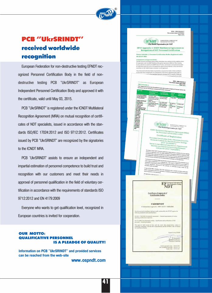
41
Б
®
PCB ‘’UkrSRINDT’’ received worldwide recognition
European Federation for non�destructive testing EFNDT rec�
ognized Personnel Certification Body in the field of non�
destructive testing PCB "UkrSRINDT" as European
Independent Personnel Certification Body and approved it with
the certificate, valid until May 03, 2015.
PCB "UkrSRINDT" is registered under the ICNDT Multilateral
Recognition Agreement (MRA) on mutual recognition of certifi�
cates of NDT specialists, issued in accordance with the stan�
dards ISO/IEC 17024:2012 and ISO 9712:2012. Certificates
issued by PCB "UkrSRINDT" are recognized by the signatories
to the ICNDT MRA.
PCB 'UkrSRINDT' assists to ensure an independent and
impartial estimation of personnel competence to build trust and
recognition with our customers and meet their needs in
approval of personnel qualification in the field of voluntary cer�
tification in accordance with the requirements of standards ISO
9712:2012 and EN 4179:2009
Everyone who wants to get qualification level, recognized in
European countries is invited for cooperation.
OUR MOTTO: QUALIFICATIVE PERSONNEL
IS A PLEADGE OF QUALITY!
Information on PCB "UkrSRINDT" and provided services
can be reached from the web�site
www.ospndt.com

8 Naberezhno�Lugova Str.,
Kiev, Ukraine, 04071
tel./fax: +38 044 531 37 27(26)E�mail: [email protected]
www.ndt.com.ua
®
OKO
ASSOCIATION