ultracraft install tips 1.0...
TRANSCRIPT

Installation of Kitchen Cabinets is NOT a Do-It-Yourself project for those without extensive experience in finish carpentry. If you are not a professional carpenter please seek help from a trained professional. This guide is meant to be used as a supplement to carpenters who are trained and familiar with cabinetry installa-
tion techniques, it is not meant to be a stand alone installation guide.
Installation Tips
Important Please Read Before Going Further!
Version 1.0 - 2009
1
Cabinet installation requires special skills and tools. If you areuncertain of any part of these basic instructions, terms or lackthe minimum listed tools, consult with your cabinet supplierfor recommended professional cabinet installation mechanics.An error during installation can result in costly repairs anddelays.
TERMS TO KNOW
Level: A horizontal plane at right angles to the plumb.
Plumb: A true vertical line. If something is “out of plumb” itis not exactly straight up and down.
Square: All lines parallel and at 90° to each other.
Rail: A horizontal framing member of a cabinet door.
Stile: A vertical framing member of a cabinet door
Stretcher: A horizontal member of a cabinet case used tomaintain square assembly. Also used to support and mountcountertops on base cabinets.
Shim: A thin wedge of wood (usually a shingle) for drivinginto crevices between cabinets and walls to plumb cabinets,and between cabinets and floor to level cabinets.
Strapping: Wood strips, normally 1”x3”x8’, used to supportwall cabinets during installation or used to construct a soffitabove cabinets.
Scribe: Cutting or trimming a cabinet to follow the contoursof adjacent floor or walls.
Soffit: The closed space between the top of the wall cabinetsand the ceiling.
Stud: An upright framing member inside a wall or partitionspaced 16” or 24” apart, center-to-center.
T-Brace: A temporary brace – constructed on site to be 541/4”tall and 16” wide – used to wedge under wall cabinets tosupport them during installation.
COMMON INSTALLATION TOOLS
For professional results have the tools you need at hand andready. Here’s a tip: save changeover time by having twocordless screwguns – one with a drill bit for predrilling screwholes and another with a screw tip.
• Power Drill • Sand Paper• Drill Bits • Block Plane• Carpenter’s Levels (2’ & 4’) • Clamps• Carpenter’s Square • Caulking•Tape Measure (1”x25’) • Chalk Line• Step ladder • Mitre Box• Nail Set • Marking Tools• Extension Cord(s) • Stud Finder• Screwdrivers • Utility Knife
(Regular & Phillips) • Pencils• Saws • Hammer
(Hand, Power, Jig, Table & Miter)
For a finished look and secure installation use joining andinstallation screws. Other options, such as drywall screws witha fierce thread pitch, may appear to be a quicker alternativebut may result in screwheads not ending up flush with thematerial. Make sure screws adequately penetrate both partswhen joining cabinetry together. Take precautions not to pierceexposed parts or adjacent cabinet interiors. Cabinetinstallation screws or similarly-sized screws should be usedto affix cabinets to the wall. Predrilling of any screw hole isessential for a finished, professional look. Finishing washersand/or cover caps should be used to complete the installation.
CabinetInstallation Screw
CabinetConnecting Bolt
21⁄2”Finishing
WasherJoiningScrew 1”
CABINET INSTALLATION
TABLE OF CONTENTS
•Terms and Tools
•Common Construction Details
•Pre-Installation
•Common Layout Heights
•Installation Tips
•Installation Steps
•Molding Tips
•Final Finishing Tips
•Hinge & Drawer Adjustments
•Special Darlington Installation Instructions

1
Cabinet installation requires special skills and tools. If you areuncertain of any part of these basic instructions, terms or lackthe minimum listed tools, consult with your cabinet supplierfor recommended professional cabinet installation mechanics.An error during installation can result in costly repairs anddelays.
TERMS TO KNOW
Level: A horizontal plane at right angles to the plumb.
Plumb: A true vertical line. If something is “out of plumb” itis not exactly straight up and down.
Square: All lines parallel and at 90° to each other.
Rail: A horizontal framing member of a cabinet door.
Stile: A vertical framing member of a cabinet door
Stretcher: A horizontal member of a cabinet case used tomaintain square assembly. Also used to support and mountcountertops on base cabinets.
Shim: A thin wedge of wood (usually a shingle) for drivinginto crevices between cabinets and walls to plumb cabinets,and between cabinets and floor to level cabinets.
Strapping: Wood strips, normally 1”x3”x8’, used to supportwall cabinets during installation or used to construct a soffitabove cabinets.
Scribe: Cutting or trimming a cabinet to follow the contoursof adjacent floor or walls.
Soffit: The closed space between the top of the wall cabinetsand the ceiling.
Stud: An upright framing member inside a wall or partitionspaced 16” or 24” apart, center-to-center.
T-Brace: A temporary brace – constructed on site to be 541/4”tall and 16” wide – used to wedge under wall cabinets tosupport them during installation.
COMMON INSTALLATION TOOLS
For professional results have the tools you need at hand andready. Here’s a tip: save changeover time by having twocordless screwguns – one with a drill bit for predrilling screwholes and another with a screw tip.
• Power Drill • Sand Paper• Drill Bits • Block Plane• Carpenter’s Levels (2’ & 4’) • Clamps• Carpenter’s Square • Caulking•Tape Measure (1”x25’) • Chalk Line• Step ladder • Mitre Box• Nail Set • Marking Tools• Extension Cord(s) • Stud Finder• Screwdrivers • Utility Knife
(Regular & Phillips) • Pencils• Saws • Hammer
(Hand, Power, Jig, Table & Miter)
For a finished look and secure installation use joining andinstallation screws. Other options, such as drywall screws witha fierce thread pitch, may appear to be a quicker alternativebut may result in screwheads not ending up flush with thematerial. Make sure screws adequately penetrate both partswhen joining cabinetry together. Take precautions not to pierceexposed parts or adjacent cabinet interiors. Cabinetinstallation screws or similarly-sized screws should be usedto affix cabinets to the wall. Predrilling of any screw hole isessential for a finished, professional look. Finishing washersand/or cover caps should be used to complete the installation.
CabinetInstallation Screw
CabinetConnecting Bolt
21⁄2”Finishing
WasherJoiningScrew 1”
CABINET INSTALLATION

18
CABINET & DRAWER CONSTRUCTION
Wall Cabinet
111⁄4” DeepAdjustable
Shelves
115⁄16”151⁄8”175⁄8”217⁄16”
24261⁄2”301⁄4”361⁄2”419⁄16”
121⁄8”
MedicineCabinet
41⁄16” DeepAdjustable
Shelves
301⁄4”361⁄2”419⁄16”
5”
Base Cabinet
223⁄16” DeepAdjustable
Shelf
341⁄2”
25⁄8”
301⁄4”
41⁄4”
24”213⁄8”
2111⁄16” Deep Drawer Box
Vanity Base Cabinet
161⁄8”, 191⁄8”Deep
AdjustableShelf
32”341⁄2”
25⁄8”
273⁄4”301⁄4”
41⁄4”
18”, 21”153⁄8”, 183⁄8”
153⁄4”, 1711⁄16” DeepDrawer Box
VanityWall Hung Cabinet
161⁄8”, 191⁄8”Deep
AdjustableShelves
2315⁄16”
81⁄16”, 109⁄16”Recommended
Heights
18”, 21”
153⁄4”, 1711⁄16” DeepDrawer Box
Tall Cabinet
223⁄16” DeepAdjustable
Shelves
Fixed Shelf
713⁄4”793⁄4”86”91”
76”84”
901⁄4”951⁄4”
21⁄2”
Geneva
25⁄8”
301⁄4”361⁄2”419⁄16”
41⁄4”
9”, 153⁄8”, 183⁄8”,213/8”12”, 18”, 21”, 24”
Notes:Geneva Door Has 5/8” Overhang On Wall Cabinets.Geneva Door Style Requires End Panels (pages 121) And C-Channel (page 136).
Wall Hung Vanities Require FieldSupplied Pedestal Base Support.
5/8”
Geneva
8”minimum
Melamine Drawer Wood Dovetail Drawer
203⁄8” Inside Depth
33⁄4” Inside Height
193⁄4” Inside Depth
31⁄4” Inside Height
5/8” Melamine All Four Sides1/4” Fully Captured Bottom75# Side Mount Glides or
Optional 75# Full Extension Side Mount GlidesDrawer Front Is Attached To Drawer Case With A 4mm Adjustment
5/8” Solid Wood Dovetail All Four Sides1/4” Fully Captured Bottom75# Undermount Glides or
Optional 75# Full Extension Undermount GlidesDrawer Front Is Attached To Drawer Case With A 4mm Adjustment
Dowel & GlueConstruction
DovetailFront & Rear
On tall cabinets install platform first- level plumb and square- then install cabinet on top of platform.For flush mount toe kick, pull platform from the wall and away from the side of the adjoining cabinet- block these voids.
IMPORTANT! Read these actual heights!

Check cabinets for damage and verify the cabinets are indeed the correct style and finish before installing. Do not install damaged cabinets without calling your designer.
Check your designer’s plans for notes and the proper placement of cabinets. Verify all the cabinets and parts are there!
If a stacked molding is shown- verify with the designer proper placement of moldings. Re-installing stacked moldings is very costly.
Before installing any cabinets- check your plans for finished ends and identify where they are.
Now is the time to verify your appliances- make sure they fit before installing cabinets!
Wall cabinets can have odd heights- verify where the top of your installation chalk lines are! For example: a 36” high wall cabinet is 36-9/16” inches
Designers in some cases order panels with only some of the edges finished. Be sure to verify which sides you need before cutting.
Find the touch-up kit. You will find it easier in some cases to touch up a part immediately after cutting it rather than waiting to the end. Place the kit where it is easily found.
Open the molding tubes by cutting the plastic plug out or pulling the plastic off with pliers- don’t waste time trying to remove the staples.
If some glue has leaked onto the inside of the cabinet, use a hard, plastic putty knife to scrape off- do not use a METAL putty knife to remove glue it can scratch the finish.
If ¾ Inch shelves were ordered- they are in separate boxes to be installed at the end of the job
Packaging straps are easily removed by turning them over and peeling them apart at the seam

14
Furring line
Optionalnailer area
Use moldings to fittop of wall cabinetsto irregular soffit.
Bottom of wallcabinets
Typical countertop is13/4" thickTop of base cabinets
Measure up from high point of floor
and draw a level lineat 341⁄2”.
SoffitMinimum Depth 13”12" (+/-)
301/4"361/2"4113/16"
533/4"
341/2"
191/4"
301/4"361/2"4113/16"
Measure And Lay Out Entire Installation Before Beginning
Ceiling Line
Mark Stud Locations16” or 24” Center-To-Center
Adjust Soffit Height& Depth To Allow ForMoldings
PRE-INSTALLATION CHECKLIST
SHIMMING
Purchase a bundle of good-quality wood shingles.They make the best shims. Screw through thecabinet, through the shim and into the wall orfloor to insure a shim will be permanent. Should
a shim slip or be knocked loose the cabinet willeventually sag or shift. Trim any exposed shimwith a sharp utility knife blade or fine-toothedhand saw.
CUTTING
Be prepared to make professional cuts for fitting ofcabinet finishing materials, like fillers. Rough cutscan be made on a table saw with sharp finishingblades. Test-cut the material first to see whatdegree of surface damage can occur. Cut edges
which will be visible in the room should beprecisely scribed and trimmed with a sharp-bladed saw. Make adjustments for final fittingwith a belt sander or plane.
INSTALLATION TIPS
84"901/4"951/4"
#1 mistake is forgetting to use shims! You can pull the cabinets out of square!
2
Understand how the full-access cabinet system is designed togo together. The goal is a perfectly-aligned, plumb, level andsquare set of cabinets. Walk through the entire installationbefore proceeding. Every dimension must be reviewed toensure that the set of cabinets going in will fit properly. Thinkahead to the trades, like floor covering installation, that willfollow cabinet installation.
All floor and wall sections need to be checked first for leveland plumb, and second for any bowing or cupping. In order tomake the installation plumb, level and square you may have toshim or scribe the cabinets.
� Carefully check all cabinetry before the start of installation.Confirm sizes, colors, finish and condition prior to removalof existing cabinetry.
� Remove and label all doors, drawers and shelving. Storethem away from the work area and extremes in temperatureand humidity. The cabinet will be lighter during installationand decorative surfaces will be less likely to be damaged.
� Assure the layout works, especially the vertical alignment ofbase and wall cabinets, and that appliances will fit in thedesigned openings.
� Turn off all water, gas and electricity to the work area.
� Remove all appliances from the kitchen.
� Remove old cabinets.
� Remove baseboard moldings and other objects on the wallwhere cabinets are to be installed. If replacing the floor,remove old floor covering.
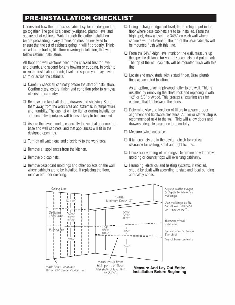
� Using a straight edge and level, find the high spot in thefloor where base cabinets are to be installed. From thehigh spot, draw a level line 341/2” on each wall wherecabinets will be fastened. The top of the base cabinets willbe mounted flush with this line.
� From the 341/2”-high level mark on the wall, measure upthe specific distance for your size cabinets and put a mark.The top of the wall cabinets will be mounted flush with thisline.
� Locate and mark studs with a stud finder. Draw plumblines at each stud location.
As an option, attach a plywood nailer to the wall. This isinstalled by removing the sheet rock and replacing it with1/2" or 5/8" plywood. This creates a fastening area forcabinets that fall between the studs.
� Determine size and location of fillers to assure properalignment and hardware clearance. A filler or starter strip isrecommended next to the wall. This will allow doors anddrawers adequate clearance to open fully.
� Measure twice; cut once.
� If tall cabinets are in the design, check for verticalclearance for ceiling, soffit and light fixtures.
� Check for overhang of moldings. Determine how far crownmolding or counter tops will overhang cabinetry.
� Plumbing, electrical and heating systems, if affected,should be dealt with according to state and local buildingand safety codes.
PRE-INSTALLATION CHECKLIST
Furring line
Optionalnailer area
Use moldings to fittop of wall cabinetsto irregular soffit.
Bottom of wallcabinets
Typical countertop is13/4" thickTop of base cabinets
Measure up from high point of floor
and draw a level lineat 341⁄2”.
SoffitMinimum Depth 13”12" (+/-)
301/4"361/2"4113/16"
533/4"
341/2"
191/4"
301/4"361/2"4113/16"
Measure And Lay Out EntireInstallation Before Beginning
Ceiling Line
Mark Stud Locations16” or 24” Center-To-Center
Adjust Soffit Height& Depth To Allow ForMoldings
84"901/4"951/4"

3
INSTALLATION TIPS
Before installing handles, knobs, pulls or other decorativehardware, replace doors and drawers to their proper positionsin your new cabinets. Adjust doors to perfect alignment usingthe 6-way-adjustable hinges. Adjust drawer heads to alignperfectly with adjacent doors by loosening or tightening thescrews inside the drawer box.
Standard margins between cabinet doors and drawer fronts isapproximately 4mm or the thickness of two dimes. This spacewill vary slightly to accommodate each unique installation.
DOORS AND DRAWERS
MOLDINGSBefore installing detail trim, like moldings, inspect thematerials for any inconsistencies. Use a professional-qualitymitre saw and make several trial cuts to test the fit of the joint.To nail the trim in place, use a professional air gun or pre-drillto avoid splitting.
Thermofoil or MDF moldings may be joined using moldingglues, such as Mitre Bond.TM These offer professional-lookingjoints without nails. Check with local woodworking supplycenters for this product.
Cuts in wood molding should be “colored” with a touch-uppen or stain in the same finish color as the cabinetry tominimize the effect of shrinkage should it occur.
If lighting is to be installed behind moldings, run a bead ofcaulking at the seam between the molding and the cabinetry.This will prevent light from being seen through the joints.
Make sure a blind corner cabinet is pulled out from the cornerthe distance called for in your kitchen plan. If decorativehandles are to be used, add a filler on the adjacent cabinet andpul the corner cabinet further out of the corner. This allowsadjacent cabinet doors to open a minimum 90°.
Blind panels are designed to have 21/8" of blind panel exposedwhen installed tight against the wall before pulling. A 3" fillerand matching overlay are to be ordered with each corner to beused as an extension of the adjacent unit and cut as necessary.
BLIND CORNER CABINETS
Soffits should be constructed and installed prior to installingthe cabinets. Allow for adequate clearance for light fixtures anddecorative molding.
Installing Without a SoffitMeasure up 191/4” from the 341/2” base-level-reference line.Place a mark on the wall, and with a level and straight edge,continue around the room drawing a line parallel to the base-level line. The bottoms of 30”-high standard wall cabinets willbe installed along this line. You may attach 1” x 2” strappingalong this line to help support the cabinets until they aresecurely fastened to the wall studs.
Installing With an Existing SoffitIf wall cabinets are to be installed against an existing ceilingsoffit, use a straight edge and level to locate its low spot. Marka level line at this low point. Tops of wall cabinets will installedalong this line. Be sure that this mark will allow opened andclosed cabinet doors to clear lighting fixtures, and overhangshave equal reveals.
Trim molding along the edge where the cabinets meet the soffit,and crown molding where the soffit meets the ceiling, not onlyadds wonderful detail but can conceal any irregularities in thesoffit and ceiling. For slight irregularities, use a good-qualitymatching caulking.
SOFFITS
Use a good-quality putty or caulking to fill nail holes andconceal joints. Using the proper touch-up materials andtechniques will ensure a professional installation. Rememberthat quality of workmanship is judged by its smallest details.
FINISHING TOUCHES
6-WAY ADJUSTABLE DOOR HINGE
Remove the cover cap if present.
Side Adjustments: Turn screw“A” in or out to adjust the doorhorizontally from left to right.Range: 4mm (5/32”)
Depth Adjustments: Loosenscrew “B” one turn, adjust doorin or out to desired position, tighten screw. Range 4mm (5/32”)
Height Adjustments: Loosen both screws “C” on mountingplate, adjust door up or down to desired position, tightenscrews. Range 6mm (5/16”)
SHIMMINGGood-quality wood shingles make the best shims. Screw throughthe cabinet, through the shim and into the wall or floor to insurea shim will be permanent. Should a shim slip or be knockedloose the cabinet will eventually sag or shift. Trim any exposedshim with a sharp utility knife blade or fine-toothed hand saw.
CUTTINGMake professional cuts for fitting of cabinet finishing materials,like fillers. Rough cuts can be made on a table saw with sharpfinishing blades. Test-cut the material first to see what degreeof surface damage can occur. Cut edges which will be visibleshould be precisely scribed and trimmed with a sharp-bladedsaw. Make adjustments for final fitting with a belt sander or plane.
B A
A B
Cabinets are to be installed without shelves, doors, or drawers left in them- you should have an empty box. Be careful to set these parts on something soft as not to damage them.Remove all doors and drawers before installation. Number them for easy replacement by writing on a roll of blue painters tape and then sticking to cabinets. Write on the roll first before putting on the part to preventimprinting your writing onto the parts.
Use connecting bolts or 1 ¼” Coarse Thread screws and a cup washer to connect the cabinets
You may find it to be an advantage to screw several boxes together at a time before attaching to the walls.It is very common join to join the right and left cabinet to a corner cabinet and then install.Line up the fronts- flush faces- then using hand squeeze clamps (usually two at a time) clamp in place.After installing screws at the face, move the clamps to the next area to be screwed together. You may find it beneficial to have a long bar clamp to join certain area’s. Trying to screw cabinets together without clamping is very frustrating as they tend to push apart during the screwing and you will find it hard to get the sides tight to each other. NEVER USE NAILS to install cabinets to walls- over time they will pull out.
Attach side cabinets to corner base cabinets and slide into place. Use shims as necessary next to walls- do not pull cabinets out of square by forcing the cabinets to the walls without shims!
Corner bases are shipped with an adjusting foot at the back. Adjust BEFORE screwing the cabinet to the wall. It is very hard if not impossible to do after!
Thermofoil door styles are shipped with Heat-Shields. A diagram of how to install is shipped on the outside of the shipping tube. Not installing the heat shields properly will void the warranty against heat damage.Roll Out Trays are adjustable- you may find it easier to do before the counter tops are installed because you have access down through the cabinet.
Loosen Tilt Tray screws before tops go on. Do not install decorative hardware through them- the trays are remov-able for cleaning into the dishwasher.
Hanging vanities must be supported at least 8” out from the wall under the bottom with solid support across the bottom. Failure to do so will cause the cabinet to fail when using heavy tops.
If the homeowner will be “heavy loading” the wall cabinets-add more screws to the installation. The whole back is a hanging rail.
Corner triangle wall cabinets use PP117 shelf clips and screw through the bottom into the shelf. For glass shelves silicone the shelves for permanent installation by applying a dab of silicone to the top of the shelf clip.
Identify your filler parts. The overlay profile fillers are sized to the cabinet doors- there are colored sub fillers that get screwed flush with the boxes. the profile fillers are installed on top of them. If your sub filler does notseem to be the right height leaving a small gap either top or bottom, chances are you have the profile filler not the sub filler!

4
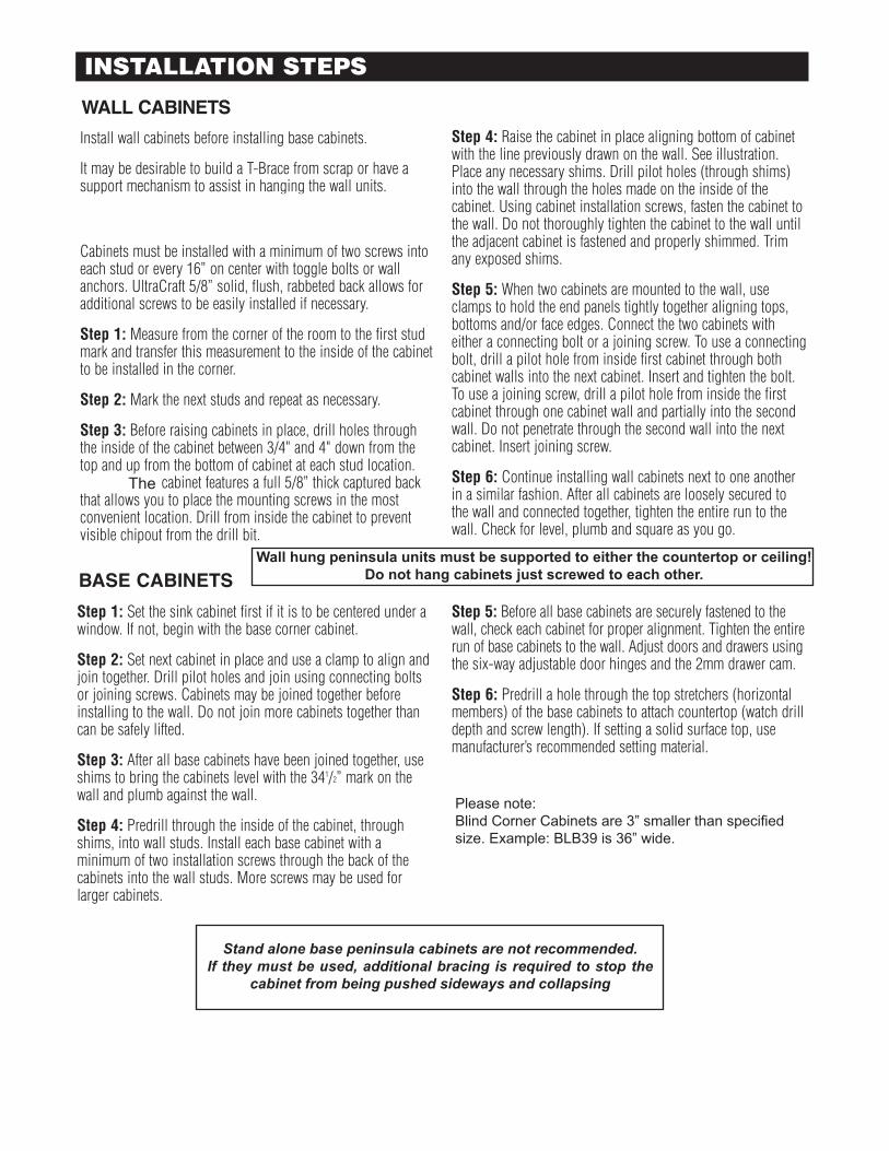
Step 1: Set the sink cabinet first if it is to be centered under awindow. If not, begin with the base corner cabinet.
Step 2: Set next cabinet in place and use a clamp to align andjoin together. Drill pilot holes and join using connecting boltsor joining screws. Cabinets may be joined together beforeinstalling to the wall. Do not join more cabinets together thancan be safely lifted.
Step 3: After all base cabinets have been joined together, useshims to bring the cabinets level with the 341/2” mark on thewall and plumb against the wall.
Step 4: Predrill through the inside of the cabinet, throughshims, into wall studs. Install each base cabinet with aminimum of two installation screws through the back of thecabinets into the wall studs. More screws may be used forlarger cabinets.
Step 5: Before all base cabinets are securely fastened to thewall, check each cabinet for proper alignment. Tighten the entirerun of base cabinets to the wall. Adjust doors and drawers usingthe six-way adjustable door hinges and the 2mm drawer cam.
Step 6: Predrill a hole through the top stretchers (horizontalmembers) of the base cabinets to attach countertop (watch drilldepth and screw length). If setting a solid surface top, usemanufacturer’s recommended setting material.
BASE CABINETS
Install wall cabinets before installing base cabinets.
It may be desirable to build a T-Brace from scrap or have asupport mechanism to assist in hanging the wall units.UltraCraft’s construction quality yields a heavier cabinet than atypical framed counterpart.
Cabinets must be installed with a minimum of two screws intoeach stud or every 16” on center with toggle bolts or wallanchors. UltraCraft 5/8” solid, flush, rabbeted back allows foradditional screws to be easily installed if necessary.
Step 1: Measure from the corner of the room to the first studmark and transfer this measurement to the inside of the cabinetto be installed in the corner.
Step 2: Mark the next studs and repeat as necessary.
Step 3: Before raising cabinets in place, drill holes throughthe inside of the cabinet between 3/4" and 4" down from thetop and up from the bottom of cabinet at each stud location.The UltraCraft cabinet features a full 5/8” thick captured backthat allows you to place the mounting screws in the mostconvenient location. Drill from inside the cabinet to preventvisible chipout from the drill bit.
Step 4: Raise the cabinet in place aligning bottom of cabinetwith the line previously drawn on the wall. See illustration.Place any necessary shims. Drill pilot holes (through shims)into the wall through the holes made on the inside of thecabinet. Using cabinet installation screws, fasten the cabinet tothe wall. Do not thoroughly tighten the cabinet to the wall untilthe adjacent cabinet is fastened and properly shimmed. Trimany exposed shims.
Step 5: When two cabinets are mounted to the wall, useclamps to hold the end panels tightly together aligning tops,bottoms and/or face edges. Connect the two cabinets witheither a connecting bolt or a joining screw. To use a connectingbolt, drill a pilot hole from inside first cabinet through bothcabinet walls into the next cabinet. Insert and tighten the bolt.To use a joining screw, drill a pilot hole from inside the firstcabinet through one cabinet wall and partially into the secondwall. Do not penetrate through the second wall into the nextcabinet. Insert joining screw.
Step 6: Continue installing wall cabinets next to one anotherin a similar fashion. After all cabinets are loosely secured tothe wall and connected together, tighten the entire run to thewall. Check for level, plumb and square as you go.
WALL CABINETS
INSTALLATION STEPS
When installing profile fillers, set the sub filler flush with the side of the cabinet. Scribe your profile filler to the wall leaving a space to the cabinet door. Remove sub filler and place 6 door bumpers on the back of the profile filler. Screw through the back of the sub filler into the profile filler. Reinstall the sub filler using the same screw holes.
Tall cabinets-level, plum and square the platform and then place the cabinet on it. The platform is setup for a recessed toe application. For a flush toe, pull the platform to the side of the cabinet box.
Decorative end panels are installed by clamping the panel on the cabinet side and installing drywall screws with cup washers. Be careful on raised panel door styles not to install screws so they blow through the face panels where the door is thinnest.
Wall Peninsula’s must have support either to the counter or to the ceiling- they cannot hang in mid-air alone!Never install Peninsula cabinets as stand alone cabinets. Columns have removable fronts- from the top of the column insert a flat blade screwdriver or stiff metal blade putty knife and pop it off. To re-install simply push it back on. Split posts and ½ posts can be screwed through the backs of the column faces so there are no fasteners showing in the faces.
Most decorative hoods have removable tops for field scribing. They are screwed on.Decorative Hoods (DRH series) have a removable front face panel for access to trades.When installing a Tilt-Out Range Hood-install it with the cabinets as you move along the run-do not leave a space and plan to install later-they are not adjustable.Hoods are supplied to fit liner/blower units. Some after market hoods may require adding a panel inside the hood for mounting.
4
Step 1: Set the sink cabinet first if it is to be centered under awindow. If not, begin with the base corner cabinet.
Step 2: Set next cabinet in place and use a clamp to align andjoin together. Drill pilot holes and join using connecting boltsor joining screws. Cabinets may be joined together beforeinstalling to the wall. Do not join more cabinets together thancan be safely lifted.
Step 3: After all base cabinets have been joined together, useshims to bring the cabinets level with the 341/2” mark on thewall and plumb against the wall.
Step 4: Predrill through the inside of the cabinet, throughshims, into wall studs. Install each base cabinet with aminimum of two installation screws through the back of thecabinets into the wall studs. More screws may be used forlarger cabinets.
Step 5: Before all base cabinets are securely fastened to thewall, check each cabinet for proper alignment. Tighten the entirerun of base cabinets to the wall. Adjust doors and drawers usingthe six-way adjustable door hinges and the 2mm drawer cam.
Step 6: Predrill a hole through the top stretchers (horizontalmembers) of the base cabinets to attach countertop (watch drilldepth and screw length). If setting a solid surface top, usemanufacturer’s recommended setting material.
BASE CABINETS
Install wall cabinets before installing base cabinets.
It may be desirable to build a T-Brace from scrap or have asupport mechanism to assist in hanging the wall units.UltraCraft’s construction quality yields a heavier cabinet than atypical framed counterpart.
Cabinets must be installed with a minimum of two screws intoeach stud or every 16” on center with toggle bolts or wallanchors. UltraCraft 5/8” solid, flush, rabbeted back allows foradditional screws to be easily installed if necessary.
Step 1: Measure from the corner of the room to the first studmark and transfer this measurement to the inside of the cabinetto be installed in the corner.
Step 2: Mark the next studs and repeat as necessary.
Step 3: Before raising cabinets in place, drill holes throughthe inside of the cabinet between 3/4" and 4" down from thetop and up from the bottom of cabinet at each stud location.The UltraCraft cabinet features a full 5/8” thick captured backthat allows you to place the mounting screws in the mostconvenient location. Drill from inside the cabinet to preventvisible chipout from the drill bit.
Step 4: Raise the cabinet in place aligning bottom of cabinetwith the line previously drawn on the wall. See illustration.Place any necessary shims. Drill pilot holes (through shims)into the wall through the holes made on the inside of thecabinet. Using cabinet installation screws, fasten the cabinet tothe wall. Do not thoroughly tighten the cabinet to the wall untilthe adjacent cabinet is fastened and properly shimmed. Trimany exposed shims.
Step 5: When two cabinets are mounted to the wall, useclamps to hold the end panels tightly together aligning tops,bottoms and/or face edges. Connect the two cabinets witheither a connecting bolt or a joining screw. To use a connectingbolt, drill a pilot hole from inside first cabinet through bothcabinet walls into the next cabinet. Insert and tighten the bolt.To use a joining screw, drill a pilot hole from inside the firstcabinet through one cabinet wall and partially into the secondwall. Do not penetrate through the second wall into the nextcabinet. Insert joining screw.
Step 6: Continue installing wall cabinets next to one anotherin a similar fashion. After all cabinets are loosely secured tothe wall and connected together, tighten the entire run to thewall. Check for level, plumb and square as you go.
WALL CABINETS
INSTALLATION STEPS
The
Wall hung peninsula units must be supported to either the countertop or ceiling!Do not hang cabinets just screwed to each other.
Stand alone base peninsula cabinets are not recommended.If they must be used, additional bracing is required to stop the
cabinet from being pushed sideways and collapsing
Please note:Blind Corner Cabinets are 3” smaller than specified size. Example: BLB39 is 36” wide.

Sub rail is to be pulled almost flush with the door faces. If you inspect the bottom edge of the sub filler- you will see where it is finished and where raw wood shows- raw wood should never show after installation.
Always plan all your molding cuts first- know how much stock you have. Check your wood grainsand match pieces for longer runs so they look good together. Because each piece of molding can have a slighter tone color due to base wood color- pair pieces on color too.
5 ½” Architectural moldings need to be cut with a 12” compound mitre saw. Standard splay angles don’t work when trying to cut the molding laying flat.
Always cut into the face of the molding with the saw.
On dark finishes- sometimes you get a better looking joint when using the touch up pen on the back-sides of the mitre cuts at the face before joining.
When using a wax crayons, use a lighter to first soften the wax. Then buff off the excess wax with a soft cloth.
Always check your panels for finished edgebanding and where the finished sides go.
Mitre bond sets in approximately 20 seconds and is intended for MDF moldings only.Cut and dry fit all moldings first. Using the bottle, apply a thin line away from the face of the molding,Spray the other end liberally. Then on a flat surface carefully align and join the moldings- hold for 20 seconds. Mitre bond on wood works only temporarily. You must micro nail after using Mitre bond on wood moldings- failure to do so will probably cause the molding to fall apart at a later date.
Install moldings either pulled out slightly from sides of cabinets or pushed back in slightly- try to not line moldings up flush with sides- create a shadow lines!
Toe kicks have end caps-check before cutting.
MOLDING TIPS
Do not reinstall doors or drawers unless you plan to adjust them right then. Unadjusted doors and drawers will in some cases bother the homeowners who do not understand they still need to be adjusted.
Doors have 6 way adjustable hinges- see next page for alignment instructions.
Drawer adjustment – be sure all drawer heads are adjusted before installing Deco hardware!Loosen the two screws at the back of the drawer heads and re-align if necessary. Deco hardware should go through the drawer box. If it is being installed above the drawer box, add extra drywall screws to the box.
The Darlington inset drawer head also has a white block under the drawer box for an in/out adjustment.When drilling for Decorative Hardware- always open the doors and check for swing before drilling- don’t ruin a door assuming you know which way it opens.
For glass doors, heat the gasket in the microwave if available for 20 seconds to make it soft and pliable. When installing VISION decorative glass in to doors- use silicone only and allow glass to dry 24 hours be-fore standing doors upright.
High Gloss Doors- Remove peel coat before installing decorative hardware
Perth Amboy door Style- Hardware is installed on the inside rail! Verify with your designer where it mounts.Using a standard hardware installation template will ruin every door!
Low voltage light transformers have six slots- however UltraCraft uses 20 watt bulbs so only three light fixtures may be plugged into a transformer.
Euro Style Legs (ELEG) are adjustable by screwing the black foot in and out.
Always remove drawer slide hardware before cutting granite tops in place for cook tops. Granite dust will destroy the ball bearings in the hardware.
FINAL FINISHING TIPS

Please read through this entire document prior to the installation ofDarlington cabinets.
Cabinet Attachment and InstallationDarlington cabinetry should be installed according to generallyaccepted practices for installing Frameless cabinetry. It is particular-ly important that all cabinets be hung plumb and level due to the tighttolerances for beaded inset cabinetry.
UltraCraft recommends that all doors and drawers be removed priorto installation and marked appropriately so that they can be rein-stalled after the cabinet boxes have been hung. (See instructions atright.) It is not necessary to remove the beaded frame from the cabi-net box.
Please note that the beaded inset frame on the Darlington cabinetryis a decorative item and lends no structural integrity to the cabinetbox itself. Therefore, it is important that cabinets are attachedthrough the end panels, not the decorative frame.
Darlington Installation Guide
Frame Attachment and AdjustmentEach frame is attached to the cabinet box by four L-shaped brackets and may be adjusted for proper alignment. For side-to-sideadjustment, loosen the screws which attach the frame brackets to theframe. The frame can be moved side-to-side 2mm in each direction.Once adjustments are made retighten screws. For height adjustment,loosen the screws which attach the frame bracket to the cabinet box.The frame can be moved up or down 4mm in each direction. Onceadjustments are made retighten screws.
WARNINGAttachment of cabinets to each other and to adjacent wallsshould be accomplished by screwing through the cabinetend panels. DO NOT attach cabinets to each other orto adjacent walls via the decorative beaded frame.Doing so will render warranty null and void.
FrameBracket
Frame
Cabinet Top
AdjustingScrew
CabinetSide
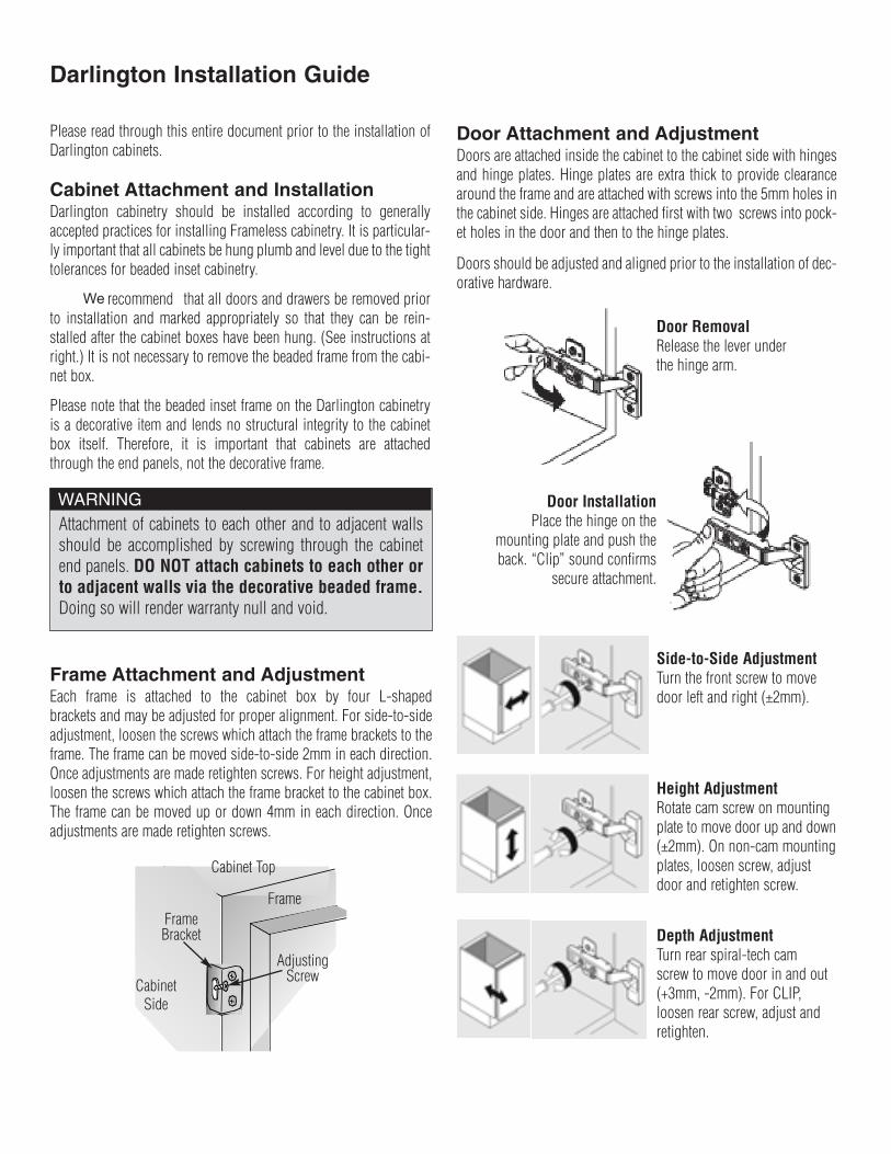
Door Attachment and AdjustmentDoors are attached inside the cabinet to the cabinet side with hingesand hinge plates. Hinge plates are extra thick to provide clearancearound the frame and are attached with screws into the 5mm holes inthe cabinet side. Hinges are attached first with two screws into pock-et holes in the door and then to the hinge plates.
Doors should be adjusted and aligned prior to the installation of dec-orative hardware.
Door RemovalRelease the lever underthe hinge arm.
Door InstallationPlace the hinge on the
mounting plate and push theback. “Clip” sound confirms
secure attachment.
Side-to-Side AdjustmentTurn the front screw to movedoor left and right (±2mm).
Height AdjustmentRotate cam screw on mountingplate to move door up and down(±2mm). On non-cam mountingplates, loosen screw, adjustdoor and retighten screw.
Depth AdjustmentTurn rear spiral-tech camscrew to move door in and out(+3mm, -2mm). For CLIP,loosen rear screw, adjust andretighten.
9/10/2006 Page 1
Please read through this entire document prior to the installation ofDarlington cabinets.
Cabinet Attachment and InstallationDarlington cabinetry should be installed according to generallyaccepted practices for installing Frameless cabinetry. It is particular-ly important that all cabinets be hung plumb and level due to the tighttolerances for beaded inset cabinetry.
UltraCraft recommends that all doors and drawers be removed priorto installation and marked appropriately so that they can be rein-stalled after the cabinet boxes have been hung. (See instructions atright.) It is not necessary to remove the beaded frame from the cabi-net box.
Please note that the beaded inset frame on the Darlington cabinetryis a decorative item and lends no structural integrity to the cabinetbox itself. Therefore, it is important that cabinets are attachedthrough the end panels, not the decorative frame.
Darlington Installation Guide
Frame Attachment and AdjustmentEach frame is attached to the cabinet box by four L-shaped brackets and may be adjusted for proper alignment. For side-to-sideadjustment, loosen the screws which attach the frame brackets to theframe. The frame can be moved side-to-side 2mm in each direction.Once adjustments are made retighten screws. For height adjustment,loosen the screws which attach the frame bracket to the cabinet box.The frame can be moved up or down 4mm in each direction. Onceadjustments are made retighten screws.
WARNINGAttachment of cabinets to each other and to adjacent wallsshould be accomplished by screwing through the cabinetend panels. DO NOT attach cabinets to each other orto adjacent walls via the decorative beaded frame.Doing so will render warranty null and void.
FrameBracket
Frame
Cabinet Top
AdjustingScrew
CabinetSide
Door Attachment and AdjustmentDoors are attached inside the cabinet to the cabinet side with hingesand hinge plates. Hinge plates are extra thick to provide clearancearound the frame and are attached with screws into the 5mm holes inthe cabinet side. Hinges are attached first with two screws into pock-et holes in the door and then to the hinge plates.
Doors should be adjusted and aligned prior to the installation of dec-orative hardware.
Door RemovalRelease the lever underthe hinge arm.
Door InstallationPlace the hinge on the
mounting plate and push theback. “Clip” sound confirms
secure attachment.
Side-to-Side AdjustmentTurn the front screw to movedoor left and right (±2mm).
Height AdjustmentRotate cam screw on mountingplate to move door up and down(±2mm). On non-cam mountingplates, loosen screw, adjustdoor and retighten screw.
Depth AdjustmentTurn rear spiral-tech camscrew to move door in and out(+3mm, -2mm). For CLIP,loosen rear screw, adjust andretighten.
9/10/2006 Page 1
We

Drawer Front AdjustmentDrawers should be adjusted and aligned prior to the installation ofdecorative hardware.
TRUE FRAMEFRAME ATTACHED TO CABINET FRONT
FIXED FRAME/DOORFRAME ATTACHED TO DOOR
17/16”
19/16”
17/16”
17/16”
17/16”
1/16” 1/16”
1/16”
1/16”
1/16”
1/16”
1/16”
1/16”
1/16”1/16”
FRAME DIMENSIONS
TRUE FRAMEFIXED
FRAME/DOOR
Side-to-Side AdjustmentFor side-to-side adjustments loosen the two screws which attach thedrawer box to the drawer front, adjust drawer front and retightenattachment screws.
Height AdjustmentFor height adjustments loosen the two screws which attach the drawerbox to the drawer front, adjust drawer front and retighten attachmentscrews. Or (for upward adjustment only) use the drawer lockingdevice located under the dovetail drawer box: press down on latch,then push latch towards back of drawer.
Depth AdjustmentTurning the screw gives up to 4mm adjustment (outward only).
Tilt AdjustmentRotate tab on rear hook.
Once doors and drawer fronts have been completely adjusted andaligned, decorative hardware can be installed.
Fixed Frame DoorsOn certain cabinets such as Diagonal Corner Wall cabinets and verynarrow cabinets such as a Tray Base 9” wide, the doors and frameswill be one piece. This is called a “fixed frame” door and both thebeaded frame and door open together. Please see the illustrationbelow.
A True Frame is attached to the front of the cabinet box and is flushon all four sides. A Fixed Frame/Door is not flush and allows a 1/16”reveal of the cabinet box. There will be a 1/16” space between theframe and moldings placed above or below the cabinet. Also, when acabinet with a Fixed Frame/Door is placed next to a cabinet with aTrue Frame the frames will not align.
If you have any questions or concerns, please contact your dealer or local UltraCraft representative.
Page 2