ultrasonic tester uk1401. user manual. content ultrasonic pulse velocity tester... · ultrasonic...
TRANSCRIPT
Ultrasonic tester UK1401. User manual.
2
CONTENT 1. OPERATION PRINCIPLE...................................................................................................3
2. DESCRIPTION ......................................................................................................................3
3. SET AND REPLACEMENT OF THE BATTERIES.........................................................4
4. EMERGENCY RESET .........................................................................................................4
5. MAINTENANCE ...................................................................................................................5
6. KEYBOARD AND KEY FUNCTIONS ...............................................................................5
7. MENU OVERVIEW ..............................................................................................................6
8. DEVICE SCREEN IN THE DIFFERENT MEASUREMENT MODES..........................8
8.1. MEASUREMENT OF VELOCITY AND TIME OF ULTRASONIC WAVES PROPAGATION WITH TURNED OFF MEMORY ................................................................................................ 8
8.2. MEASUREMENT OF VELOCITY AND TIME OF ULTRASONIC WAVES PROPAGATION WITH TURNED ON MEMORY .................................................................................................. 8
8.3. MEASUREMENT OF CRACK DEPTH ................................................................................. 9 8.4. AUTOMATIC GAIN CONTROL (AGC) MODE..................................................................... 9
9. PREPARATIONS FOR MEASUREMENTS....................................................................10
10. DETECTION OF VELOCITY OR TIME OF ULTRASONIC WAVES PROPAGATION..............................................................................................................................11
11. DETECTION OF CRACK DEPTH, COMING TO A SURFACE .................................12
12. OPERATIONS WITH MEMORY .....................................................................................13
12.1. RECORD READINGS (TIME OR VELOCITY OF ULTRASONIC WAVES PROPAGATION) IN THE MEMORY............................................................................................................. 13
12.2. REVIEWING OF THE READINGS BY LISTING THE GROUPS................................................. 14 12.3. REVIEWING THE READINGS BY LISTING CELL NUMBERS IN THE CURRENT GROUPS ............ 15 12.4. CORRECTION OF READINGS SAVED IN MEMORY............................................................. 15 12.5. CLEARING MEMORY ................................................................................................... 16
13. DATA TRANSFER TO PC .................................................................................................17
13.1. SETUP OF THE INFRARED PORT .................................................................................. 17 13.2. INSTALLATION OF THE PROGRAM FOR DATA TRANSMISSION FROM UK1401 TO THE PC .. 17 13.3. DATA TRANSFER FROM UK1401 ................................................................................ 18 13.4. LICENSE AGREEMENT................................................................................................. 19 13.5. LIMITED WARRANTY. .................................................................................................. 20
14. WARRANTY ON THE PRODUCT...................................................................................20
15. INSTRUCTIONS ON TESTING THE CONCRETE’S SOLIDITY IN MONOLITH STRUCTURES WITH SURFACE SOUNDING ULTRASONIC METHOD ...........................22
15.1. INTRODUCTION .......................................................................................................... 22 15.2. APPLICATION OF SURFACE SOUNDING METHOD............................................................. 22 15.3. PREPARATIONS FOR TESTING ..................................................................................... 22 15.4. USING OF UNIVERSAL CALIBRATION DEPENDENCE FOR APPROXIMATE DETECTION OF
CONCRETE’S SOLIDITY................................................................................................ 24 15.5. TESTING AND DETECTION OF CONCRETE’S SOLIDITY IN STRUCTURES.............................. 25
16. TABLE OF VELOCITIES OF LONGITUDINAL ULTRASONIC WAVES IN MATERIALS, M/S...........................................................................................................................27
Ultrasonic tester UK1401. User manual.
3
1. OPERATION PRINCIPLE
UK1401 ultrasonic tester is applicable for measurement of ultrasound velocity and time of longitudinal ultrasound waves dispersion in solid materials at surface sounding testing method, when the purpose of testing is to detect and estimate the solidity and homogeneity of material and structures.
This estimation is based on the correlation of ultrasound waves velocity in material to its physic and mechanical characteristics and physical statement.
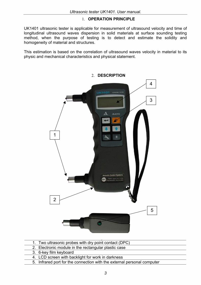
2. DESCRIPTION
1. Two ultrasonic probes with dry point contact (DPC) 2. Electronic module in the rectangular plastic case 3. 6-key film keyboard 4. LCD screen with backlight for work in darkness 5. Infrared port for the connection with the external personal computer
1
4
3
5
2
Ultrasonic tester UK1401. User manual.
4
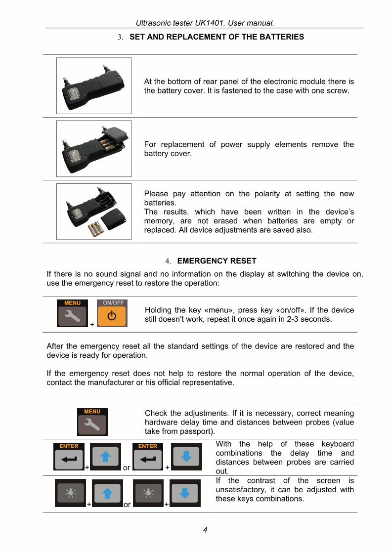
3. SET AND REPLACEMENT OF THE BATTERIES
At the bottom of rear panel of the electronic module there is the battery cover. It is fastened to the case with one screw.
For replacement of power supply elements remove the battery cover.
Please pay attention on the polarity at setting the new batteries. The results, which have been written in the device’s memory, are not erased when batteries are empty or replaced. All device adjustments are saved also.
4. EMERGENCY RESET If there is no sound signal and no information on the display at switching the device on, use the emergency reset to restore the operation:
+
Holding the key «menu», press key «on/off». If the device still doesn’t work, repeat it once again in 2-3 seconds.
After the emergency reset all the standard settings of the device are restored and the device is ready for operation. If the emergency reset does not help to restore the normal operation of the device, contact the manufacturer or his official representative.
Check the adjustments. If it is necessary, correct meaning hardware delay time and distances between probes (value take from passport).
+ or +
With the help of these keyboard combinations the delay time and distances between probes are carried out.
+ or +
If the contrast of the screen is unsatisfactory, it can be adjusted with these keys combinations.
Ultrasonic tester UK1401. User manual.
5
5. MAINTENANCE
The maintenance service of the tester consists, basically, in clearing the device and probes from the dust and dirty and periodic charge accumulators at complete brightening symbol battery on the screen of the device. Accumulators of the given type it is not recommended frequently recharge, if they still completely were not unloaded, as it can result in reduction of their resource of work. The charge accumulators is carried out with the help universal charging unit delivered in the complete set of accessories to the device, during 12-16 hours.
If to use dry supply elements it is possible to work up to their complete category, after which it is necessary elements at once to replace or even to delete from the device what to avoid pollution by its flowed out electro cast. Once in the month expediently these elements to get from the device and to examine as electrolyte can sometimes follow and from not unloaded elements. It is necessary immediately to replace spoiled elements.
Practically singular defect, which user can remove independently, is the infringement of electrical contact in the circuit supper elements. It is expressed in absence of any symbols on the indicator after pressing the key “on/off” or in indication of the lowered voltage, when the battery obviously normal. If it has taken place, and you are sure, that the supply elements are charged, take them from the device and wipe their contacts by spirit or clean fine emery paper. If it has not helped, it is necessary to address in the firm - manufacturer.
It is not recommended to assort the device without emergency, as it can result in casual damage of its internal devices. At occurrence of malfunctions tester or any questions on its use it is necessary to contact to the representatives firm on telephones specified in the passport of the device.
6. KEYBOARD AND KEY FUNCTIONS

Ultrasonic tester UK1401. User manual.
6
7. MENU OVERVIEW
TIME / VELOCITY / CRACK MEMORY 0 ÷ 4000 LINK SOUND ON /OFF FREQUENCY 1 / 2 / 3 / 4 / 5 / 6 DELAY 11,9 BASE 150 OUTPUT CLEAR METRICS/ ENGLISH AGC ON / OFF
«On» and «Off» of the device. The device also «switches off» automatically, if the operator does not press any key during 4 minutes after taking the probe from the surface.
Display backlight ON and OFF. Each pressing switches «on» or «off» the backlight.
+
When used together these keys improve the contrast.
+
When used together these keys darken the image of the contrast.
In the mode of device setting – changes setting parameters and starts selected operations from menu. In the measurement mode data enters in the free sell memory.
or
Allows choose menu line in the setting mode. In the flaw detection mode change the amplification coefficient of the receiving path. In the memory viewing and correction mode – change the result and group numbers.
Goes to the main menu. Also switched the memory viewing and correction mode
+
Switches on memory reviewing and correction of the result from current group.
+
Switches on memory reviewing and correction of the results with listing group numbers
Ultrasonic tester UK1401. User manual.
7
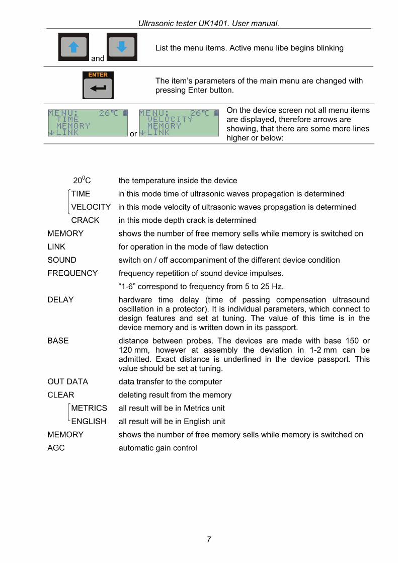
and List the menu items. Active menu libe begins blinking
The item’s parameters of the main menu are changed with pressing Enter button.
or
On the device screen not all menu items are displayed, therefore arrows are showing, that there are some more lines higher or below:
200С the temperature inside the device TIME in this mode time of ultrasonic waves propagation is determined VELOCITY in this mode velocity of ultrasonic waves propagation is determined CRACK in this mode depth crack is determined
MEMORY shows the number of free memory sells while memory is switched on LINK for operation in the mode of flaw detection SOUND switch on / off accompaniment of the different device condition FREQUENCY frequency repetition of sound device impulses.
“1-6” correspond to frequency from 5 to 25 Hz. DELAY hardware time delay (time of passing compensation ultrasound
oscillation in a protector). It is individual parameters, which connect to design features and set at tuning. The value of this time is in the device memory and is written down in its passport.
BASE distance between probes. The devices are made with base 150 or 120 mm, however at assembly the deviation in 1-2 mm can be admitted. Exact distance is underlined in the device passport. This value should be set at tuning.
OUT DATA data transfer to the computer CLEAR deleting result from the memory
METRICS all result will be in Metrics unit ENGLISH all result will be in English unit
MEMORY shows the number of free memory sells while memory is switched on AGC automatic gain control
Ultrasonic tester UK1401. User manual.
8
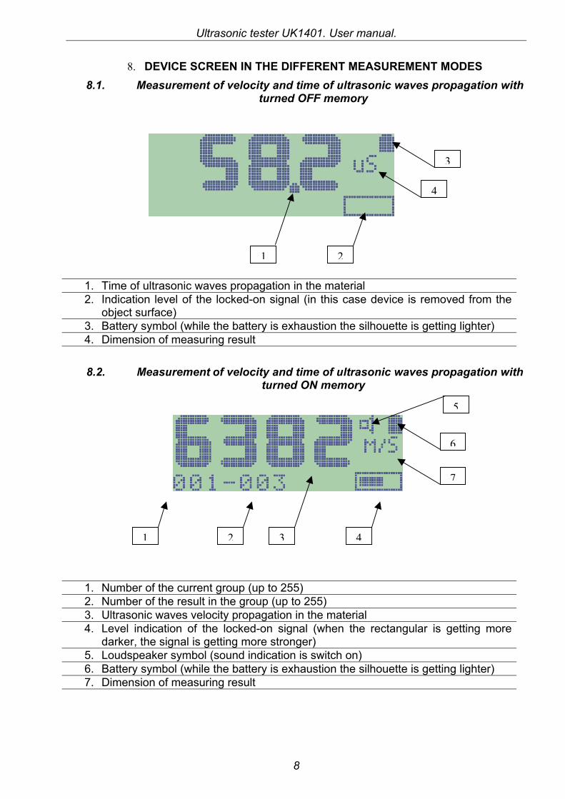
8. DEVICE SCREEN IN THE DIFFERENT MEASUREMENT MODES 8.1. Measurement of velocity and time of ultrasonic waves propagation with
turned OFF memory
1. Time of ultrasonic waves propagation in the material 2. Indication level of the locked-on signal (in this case device is removed from the
object surface) 3. Battery symbol (while the battery is exhaustion the silhouette is getting lighter) 4. Dimension of measuring result
8.2. Measurement of velocity and time of ultrasonic waves propagation with turned ON memory
1. Number of the current group (up to 255) 2. Number of the result in the group (up to 255) 3. Ultrasonic waves velocity propagation in the material 4. Level indication of the locked-on signal (when the rectangular is getting more
darker, the signal is getting more stronger) 5. Loudspeaker symbol (sound indication is switch on) 6. Battery symbol (while the battery is exhaustion the silhouette is getting lighter) 7. Dimension of measuring result
21
4
3
1 2 4
7
6
5
3
Ultrasonic tester UK1401. User manual.
9
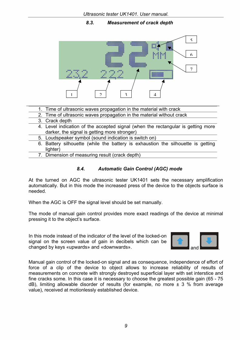
8.3. Measurement of crack depth
1. Time of ultrasonic waves propagation in the material with crack 2. Time of ultrasonic waves propagation in the material without crack 3. Crack depth 4. Level indication of the accepted signal (when the rectangular is getting more
darker, the signal is getting more stronger) 5. Loudspeaker symbol (sound indication is switch on) 6. Battery silhouette (while the battery is exhaustion the silhouette is getting
lighter) 7. Dimension of measuring result (crack depth)
8.4. Automatic Gain Control (AGC) mode
At the turned on AGC the ultrasonic tester UK1401 sets the necessary amplification automatically. But in this mode the increased press of the device to the objects surface is needed.
When the AGC is OFF the signal level should be set manually.
The mode of manual gain control provides more exact readings of the device at minimal pressing it to the object’s surface.
In this mode instead of the indicator of the level of the locked-on signal on the screen value of gain in decibels which can be changed by keys «upwards» and «downwards». and .
Manual gain control of the locked-on signal and as consequence, independence of effort of force of a clip of the device to object allows to increase reliability of results of measurements on concrete with strongly destroyed superficial layer with set interstice and fine cracks some. In this case it is necessary to choose the greatest possible gain (65 - 75 dB), limiting allowable disorder of results (for example, no more ± 3 % from average value), received at motionlessly established device.
2 43
5
7
6
1
Ultrasonic tester UK1401. User manual.
10
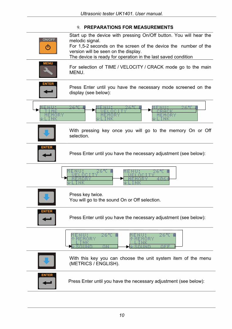
9. PREPARATIONS FOR MEASUREMENTS
Start up the device with pressing On/Off button. You will hear the melodic signal. For 1,5-2 seconds on the screen of the device the number of the version will be seen on the display. The device is ready for operation in the last saved condition
For selection of TIME / VELOCITY / CRACK mode go to the main MENU.
Press Enter until you have the necessary mode screened on the display (see below):
With pressing key once you will go to the memory On or Off selection.
Press Enter until you have the necessary adjustment (see below):
Press key twice. You will go to the sound On or Off selection.
Press Enter until you have the necessary adjustment (see below):
With this key you can choose the unit system item of the menu (METRICS / ENGLISH).
Press Enter until you have the necessary adjustment (see below):
Ultrasonic tester UK1401. User manual.
11
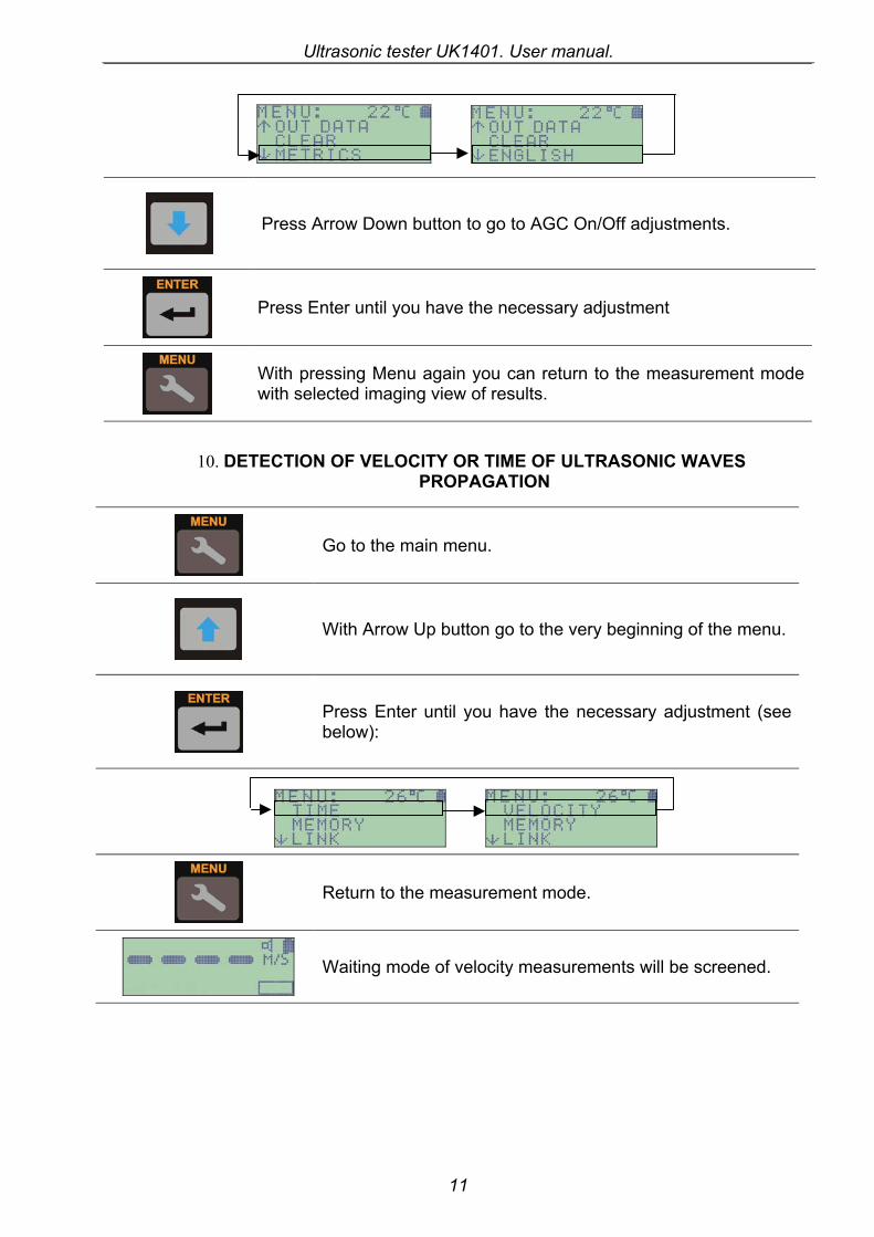
Press Arrow Down button to go to AGC On/Off adjustments.
Press Enter until you have the necessary adjustment
With pressing Menu again you can return to the measurement mode with selected imaging view of results.
10. DETECTION OF VELOCITY OR TIME OF ULTRASONIC WAVES PROPAGATION
Go to the main menu.
With Arrow Up button go to the very beginning of the menu.
Press Enter until you have the necessary adjustment (see below):
Return to the measurement mode.
Waiting mode of velocity measurements will be screened.
Ultrasonic tester UK1401. User manual.
12
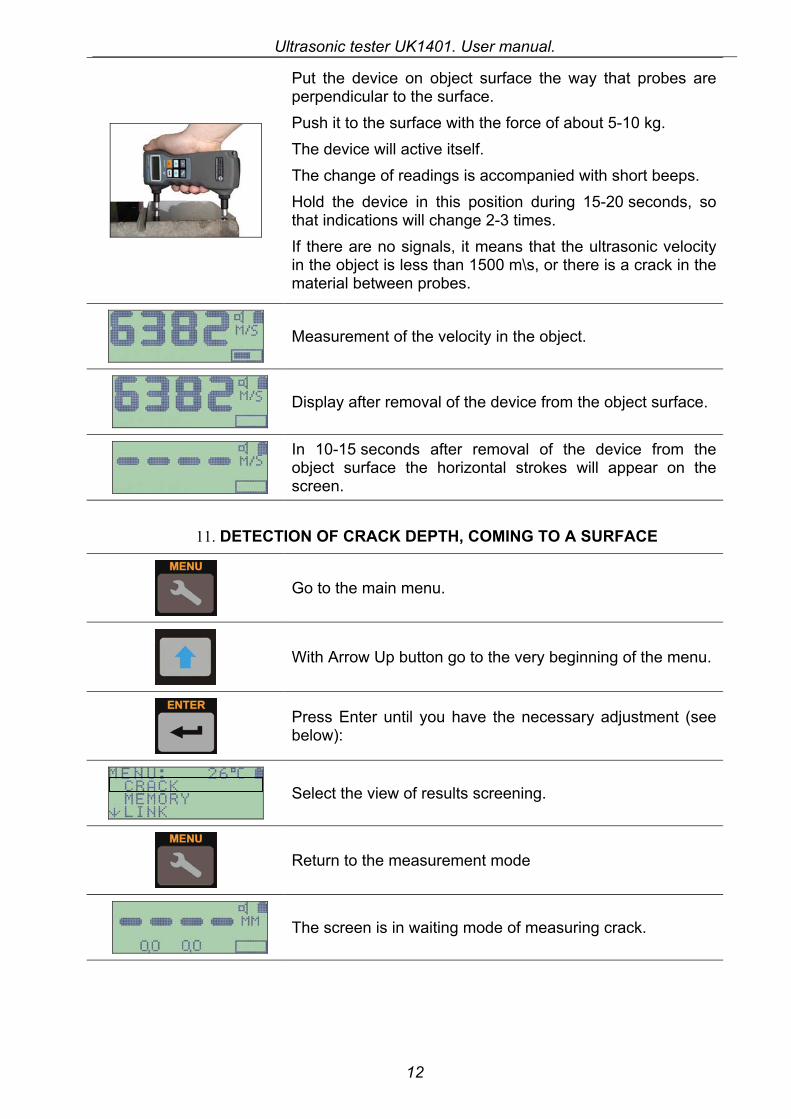
Put the device on object surface the way that probes are perpendicular to the surface. Push it to the surface with the force of about 5-10 kg. The device will active itself. The change of readings is accompanied with short beeps. Hold the device in this position during 15-20 seconds, so that indications will change 2-3 times. If there are no signals, it means that the ultrasonic velocity in the object is less than 1500 m\s, or there is a crack in the material between probes.
Measurement of the velocity in the object.
Display after removal of the device from the object surface.
In 10-15 seconds after removal of the device from the object surface the horizontal strokes will appear on the screen.
11. DETECTION OF CRACK DEPTH, COMING TO A SURFACE
Go to the main menu.
With Arrow Up button go to the very beginning of the menu.
Press Enter until you have the necessary adjustment (see below):
Select the view of results screening.
Return to the measurement mode
The screen is in waiting mode of measuring crack.

Ultrasonic tester UK1401. User manual.
13
Put the device on the object’s surface parallel to crack on the distance 10-15 mm from it. Push it with the force of about 5-10 kg. The device will activate itself. The change of indications is accompanied with short beeps.
The time of ultrasound propagation in the object without crack in microseconds. The time is measured until the device is removed from the surface.
Press for obtain the meaning as a base value.
The Base value is added in the device memory.
Put the device on the surface, perpendicular to crack.
Depth of crack meaning, measured in metrics units.
12. OPERATIONS WITH MEMORY 12.1. Record readings (Time or Velocity of Ultrasonic Waves Propagation) in
the memory
Go to the main menu.
Choose Memory On or Off item.
Press Enter until you have the necessary adjustment (see below):
Figure in the MEMORY line means quantity of free cells.

Ultrasonic tester UK1401. User manual.
14
Return to the measurement mode.
“001” means number of group, “004” means number of the result in this group.
Put the device on object the way, that probes are perpendicular to the surface. Push it with force of about 5-10 kg. The device will pass in the active state. The change of indications is accompanied by short beeps. Fix the device in such condition during 15-20 seconds, so the indications will change 2-3 times.
On the screen you will see the results of velocity measurement in the object.
Display after removal of the device from the object surface (indicator of the level of receiving signal is light).
Press Enter for 10-15 seconds after removal the device from the tested object surface. The short signal will sound.
Go to the next cell. If number of result in-group is equal 255, the next measurement of the device will record in next group.
IT IS POSSIBLE TO BEGIN NEW GROUP WITHOUT WAITING UNTIL THE CURRENT GROUP IS FULL. Put the device on the object surface, make the measurement, press and held the button for 2-3 seconds. Short signal will sound. The result will be recоrded in the new group under the № 001.
The number of the free sell in the new group.
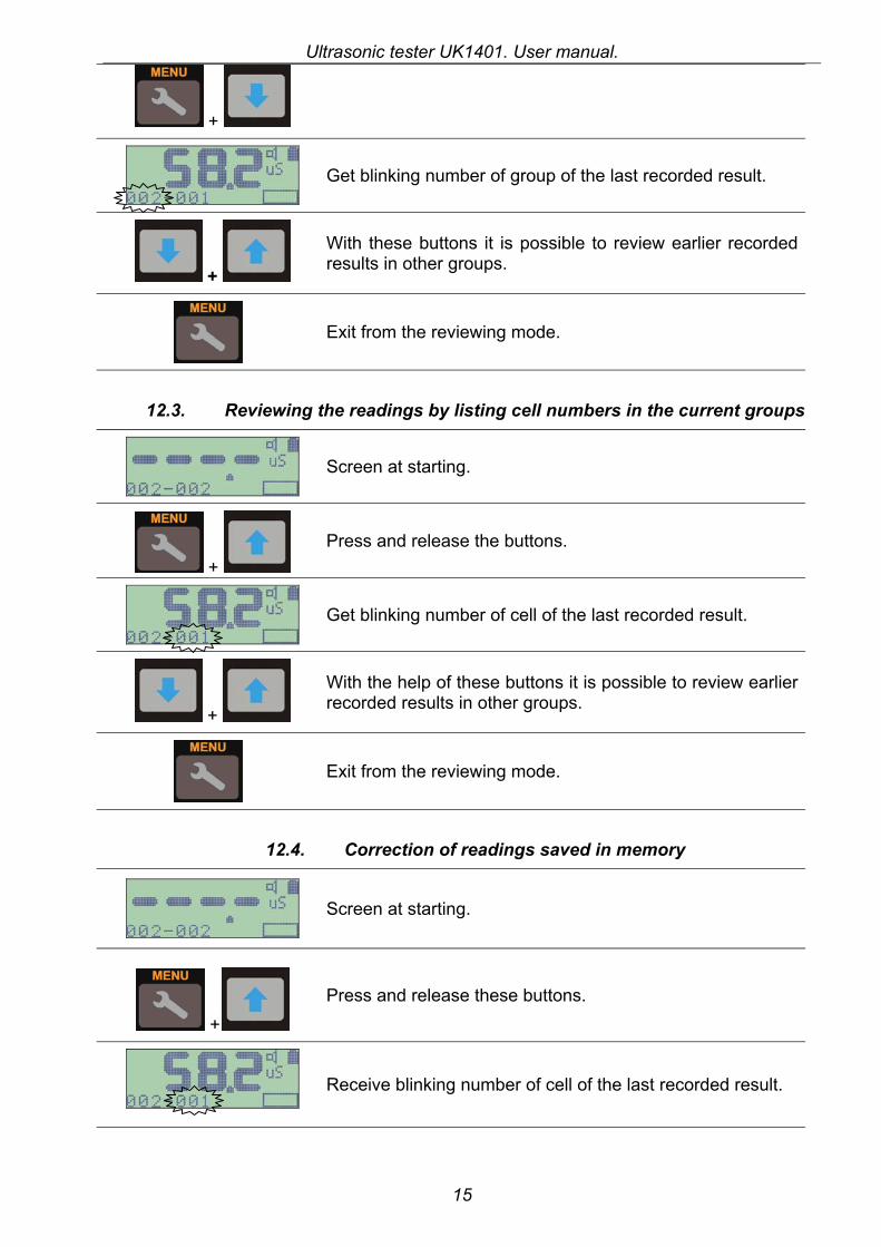
12.2. Reviewing of the readings by listing the groups
Screen at starting.
Press and release the buttons.
Ultrasonic tester UK1401. User manual.
15
+
Get blinking number of group of the last recorded result.
+
With these buttons it is possible to review earlier recorded results in other groups.
Exit from the reviewing mode.
12.3. Reviewing the readings by listing cell numbers in the current groups
Screen at starting.
+ Press and release the buttons.
Get blinking number of cell of the last recorded result.
+
With the help of these buttons it is possible to review earlier recorded results in other groups.
Exit from the reviewing mode.
12.4. Correction of readings saved in memory
Screen at starting.
+
Press and release these buttons.
Receive blinking number of cell of the last recorded result.

Ultrasonic tester UK1401. User manual.
16
+
With the help of these buttons it is possible to choose and adjust earlier recorded results.
Put the device on the object the way, that probes are perpendicular to the surfaces. Push the device with force of about 5-10 kg. The device will pass in the active state. The change of indications is accompanied with short beeps. Hold the device in such state during 15-20 seconds, so the indications will change 2-3 times.
Receive the new result.
Record it n this cell. Number of cell will blink all the same. That means you can make measurement once again.
Exit from the correction mode.
12.5. Clearing memory
Go to the main menu.
The memory should be switched on. There should be figures In the line MEMORY.
or
With the help of these buttons select the line CLEAR. Line should start blinking:
Function of Data deleting.
Press Enter button. On the screen will appear an inscription PRESS ENTER
If the data is not needed just press Enter! Remember you will not be able to restore the meanings, so be sure that you want to delete all the data from the memory. To cancel clearing just press «menu».
The melodious signal will sound. The device memory will be cleared. The device will return in the measurement mode.
Ultrasonic tester UK1401. User manual.
17
13. DATA TRANSFER TO PC For data transfer to the PC Infrared port is used. See description of the device on the page 3 to locate the infrared port on UK1401.
13.1. Setup of the Infrared Port ATTENTION: Do not install any drivers for IR-adaptor. If the system asks to install the device, cancel it. If the system has set the drivers automatically, delete the device from the system. Our software will set all the necessary drivers for IR-adaptor Connect IR-adaptor, delivered in the basic kit, to the PC through a suitable plug on the back panel of the computer.
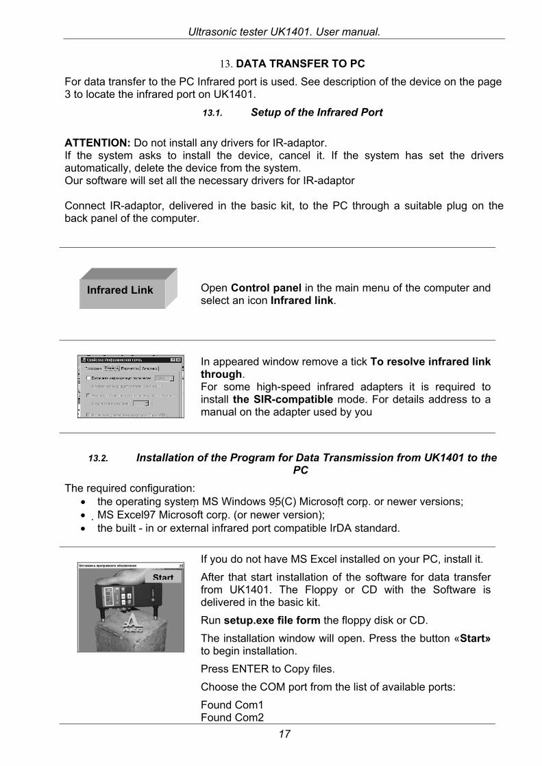
Open Control panel in the main menu of the computer and select an icon Infrared link.
In appeared window remove a tick To resolve infrared link through. For some high-speed infrared adapters it is required to install the SIR-compatible mode. For details address to a manual on the adapter used by you
13.2. Installation of the Program for Data Transmission from UK1401 to the PC
The required configuration: • the operating system MS Windows 95(C) Microsoft corp. or newer versions; • MS Excel97 Microsoft corp. (or newer version); • the built - in or external infrared port compatible IrDA standard.
If you do not have MS Excel installed on your PC, install it. After that start installation of the software for data transfer from UK1401. The Floppy or CD with the Software is delivered in the basic kit. Run setup.exe file form the floppy disk or CD. The installation window will open. Press the button «Start» to begin installation. Press ENTER to Copy files. Choose the COM port from the list of available ports: Found Com1 Found Com2
Infrared Link
Start
Ultrasonic tester UK1401. User manual.
18
Found Com3 You will see “Begin data transmission from your device” and “Infrared port detection...” At this moment, turn on UK1401. Go to the menu, choose LINK line and press ENTER. UK1401 will switch to LINK mode. And will start to send information through its IR-port. Face Infrared port of the device to the IR adaptor. You will get the announcement that the COM port is detected and then that the installation is successfully finished. Press OK. The installation window will close and the software will be ready for operation.
The device is still in LINK mode. Press ENTER to exit from this mode. For data transfer follow the instructions in item 13.3 Data transfer of this Operation manual.
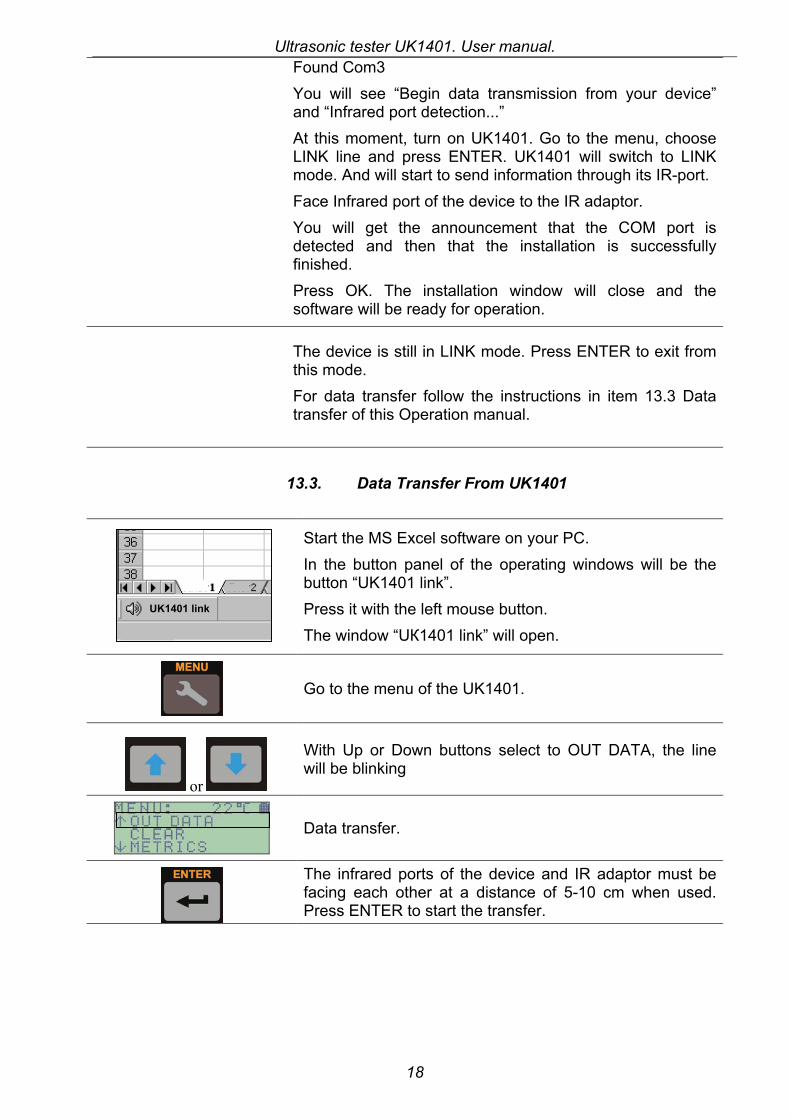
13.3. Data Transfer From UK1401 Start the MS Excel software on your PC.
In the button panel of the operating windows will be the button “UK1401 link”. Press it with the left mouse button. The window “UК1401 link” will open.
Go to the menu of the UK1401.
or
With Up or Down buttons select to OUT DATA, the line will be blinking
Data transfer.
The infrared ports of the device and IR adaptor must be facing each other at a distance of 5-10 cm when used. Press ENTER to start the transfer.
UK1401 link
Ultrasonic tester UK1401. User manual.
19
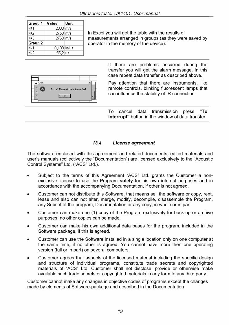
In Excel you will get the table with the results of measurements arranged in groups (as they were saved by operator in the memory of the device).
If there are problems occurred during the
transfer you will get the alarm message. In this case repeat data transfer as described above. Pay attention that there are instruments, like remote controls, blinking fluorescent lamps that can influence the stability of IR connection.
To cancel data transmission press "To interrupt" button in the window of data transfer.
13.4. License agreement
The software enclosed with this agreement and related documents, edited materials and user’s manuals (collectively the “Documentation”) are licensed exclusively to the “Acoustic Control Systems” Ltd. (“ACS” Ltd.).
• Subject to the terms of this Agreement “ACS” Ltd. grants the Customer a non-exclusive license to use the Program solely for his own internal purposes and in accordance with the accompanying Documentation, if other is not agreed.
• Customer can not distribute this Software, that means sell the software or copy, rent, lease and also can not alter, merge, modify, decompile, disassemble the Program, any Subset of the program, Documentation or any copy, in whole or in part.
• Customer can make one (1) copy of the Program exclusively for back-up or archive purposes; no other copies can be made.
• Customer can make his own additional data bases for the program, included in the Software package, if this is agreed.
• Customer can use the Software installed in a single location only on one computer at the same time, if no other is agreed. You cannot have more then one operating version (full or in part) on several computers.
• Customer agrees that aspects of the licensed material including the specific design and structure of individual programs, constitute trade secrets and copyrighted materials of “ACS” Ltd. Customer shall not disclose, provide or otherwise make available such trade secrets or copyrighted materials in any form to any third party.
Customer cannot make any changes in objective codes of programs except the changes made by elements of Software-package and described in the Documentation
Error! Repeat data transfer!
Ultrasonic tester UK1401. User manual.
20
13.5. Limited warranty.
“Acoustic Control Systems” Ltd. warrants the quality of the data on the electronic medium, the substantial operation of the Program when used in accordance with Documentation, the accordance of the components of the Software package to the specifications and the quality of documents edition.
Except as expressed above the software is provided “AS IS” without warranties of any kind, express or implied warranty with respect to the programs, documentation including any implied warranty of fitness for a particular purpose. “ACS” Ltd. does not warrant that any program will be error-free or that any defects that may exist in any program can be corrected.
Each Recipient is solely responsible for determining the appropriateness of using the Program and assumes all risks associated with its exercise of rights under this Agreement, including but not limited to the risks and costs of program errors, compliance with applicable laws, damage to or loss of data, programs or equipment, and unavailability or interruption of operations.
In no event shall “ACS” ltd. be liable for any loss of profits, use, business or for any incidental, indirect, special, consequential or exemplary damages whatsoever including but not limited to damages resulting from loss of anticipated savings or lost data.
14. WARRANTY ON THE PRODUCT
Acoustic Control Systems Ltd. (ACS Ltd.) warrants the device for 1 year from the date of sale, excluding the transducer. The standard warranty period for the transducer is 3 months from the date of sale. If something happens to the device during the warranty period for reasons covered by the warranty, ACS Ltd. at its option will:
• Repair the Product or • Replace the product if is unable to repair it.
This warranty does not cover damages due to external causes, including accident, usage not in accordance with product instruction, misuse. The warranty also looses its validity if the customer tried to repair the device himself or under mechanical effect the device became nonrepairable.
As the tester UK1401 is the complex product and the repair of its electronic units requires special equipment, the firm-manufacturer does not recommend to repair the device independently. Because of this the firm does not deliver the users the electrical circuit of the device and repair documentation.
Warranties lose force, if the user independently tried to repair electronic units of the tester or if the device has undergone to strong mechanical influences, as the result of which became pluck-out.
Accumulator delivered with the device, are in the rarefied condition, as it is recommended by rules of their storage, therefore before the beginning of operation of the device they should be charged.
Ultrasonic tester UK1401. User manual.
21
Accordingly to the Article 23 Law of Russian Federation “About the providing unity for measuring devices”, UK1401 ultrasonic tester is calibrated right after its production. This calibration is marked in the technical passport of the device with a special stamp. The device’s calibration is also made during usage of the device either by the manufacturer or by the standardizing departments of the enterprises that use ultrasonic tester UK1401.
For checking the device in the process of use a special control testing block from Plexiglas is delivered with the device. The sizes of this block are 190x40x25 mm. On the sample stays the serial number of the device and the right ultrasonic time that the device when operating correctly should read (show) at the temperature 20oC ±1oC. The temperature indication is important because the Plexiglas has temperature factor of ultrasound velocity -0,12%/oС. That factor makes influence on the results increasing measurable time for 0,07 microseconds at the increase of temperature on 1oC at base of 150 mm.
The check should be made as follows:
Turn on the tester and put it on the control sample. Ultrasonic probes should be put in the deepening specially made on one of the sides of the sample. Press the device with effort of 5-10 kg and fix it in this position. Hold it for 5-10 seconds. Write down the indications of the device. Remove the device from the sample.
It is necessary to repeat this procedure for 20 times. After that calculate the average meaning of the measured ultrasound time and compare it with the time, that is written on the control sample written.
The readings of the device should not differ from the written time on more then ±0,5 microseconds with taking into the account the temperature coefficient.
For all the questions, please, contact the manufacturer:
Acoustic Control Systems Ltd. 119048, Moscow, POBox 148 tel/fax +7 095 244-3194, 244-2535, 245-5896 e-mail [email protected] website www.acsys.ru
Ultrasonic tester UK1401. User manual.
22
15. INSTRUCTIONS ON TESTING THE CONCRETE’S SOLIDITY IN MONOLITH STRUCTURES WITH SURFACE SOUNDING ULTRASONIC METHOD
15.1. Introduction Accordingly to GOST 17624-87 “Concrete. Ultrasonic methods of solidity estimation”, the testing of monolithic structures with ultrasonic methods can only be made with through sounding way of testing. Operation experience of laboratory of reinforced concrete structures and quality estimation in State Unitary Organization “Scientific Research Institute of Reinforced Concrete” showed also the possibility of using surface sounding way of ultrasonic testing for nondestructive testing of concrete solidity in monolithic structures. These recommendations were made as addition to GOST 17624-87 and have the main rules of testing the compressive strength of concrete in monolithic structures with the help of surface sounding method.
15.2. Application of surface sounding method 1. The method of “surface sounding” can be used for testing the concrete’s solidity at
the moment when the cast formwork is taken off, or for testing the concrete’s solidity in terms determined by the project or technical documentation, and also it can be used for engineering monitoring of exploitable or reconstructed monolithic structures.
2. The concrete’s solidity is detected by the following experimentally established calibration dependences: “Velocity of ultrasound dissemination at surface sounding – concrete’s solidity” and “time of ultrasound dissemination at surface sounding – concrete’s solidity”.
3. Surface sounding can be used for testing solidity both of heavy and light concrete of B7,5 to B50 types; the calibration dependences should meet the demands described in the item 9 of “Preparations for Testing” of this Instruction (see below).
4. Ultrasonic Testing can be made with the help of devices that meet the requirements of Standard GOST 17624-87 of RF and that can provide time and velocity measurements of ultrasound dissemination on 120mm base or larger. It is recommended to use the probes with dry point contact (for example UK1401).
15.3. Preparations for testing
1. For determination of concrete’s solidity in structures you need preliminarily to build the calibration dependence.
2. Calibration dependence is based on the results of parallel testing with two different ways (ultrasonic testing and “avulsion with break” method) of the same parts of concrete structures under standard GOST 22690-88 or it can also base on the results of ultrasonic testing of structure’s parts and testing of samples, cut from the same parts of structure (accordingly to GOST 25870-90). It is also possible to built the calibration dependence on the results of ultrasonic testing of cube-samples and following their testing under press. Cubes must be in the same environmental conditions, as the structures; ultrasonic testing on these cubes must be taken in the same conditions as the testing of structures themselves.
3. Building of calibration dependences based on the results of samples testing is made accordingly to the standard GOST 17624-87.
Ultrasonic tester UK1401. User manual.
23
4. When you build the calibration dependence based on the results of parallel testing with two methods: Ultrasonic method and “Avulsion with break” method or testing the samples, cut from the prepared for testing structures, you need to remember the following things:
• The ultrasonic testing is made on the subjected to general testing structures or in the areas of structures;
• The points of the minimal and maximal velocity (or time) of ultrasound dissemination are detected.
After that you need to choose not less then 12 areas, including the areas where the velocity (time) of ultrasound dissemination is minimal, maximal and middle. After the ultrasound testing these areas are tested with “avulsion with break” method or the samples from these areas are chosen for testing under pressure.
5. The concrete’s age on the single areas should not differ on more then 25% from the middle age of concrete in areas of structure, or structure itself, or group of structures, subjected to testing. The exception is made for building the calibration dependence for estimation concrete’s solidity at engineering testing, when the difference in concrete’s age is not regulated.
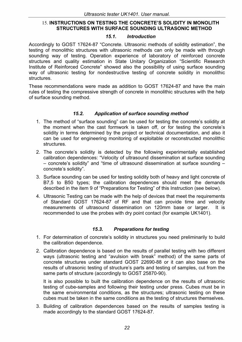
6. On each area with the help of magnet device the location of reinforcement in the concrete is detected and then with the help of ultrasonic device the ultrasonic velocity (time) in it is measured. Ultrasonic testing is made not less then 2 times. The testing is made in two directions perpendicular to each other. The sounding is made under 45° to the reinforcement direction: parallel and perpendicular to it. At sounding in the parallel to the reinforcement direction, the sounding line lies between the reinforcement cores (on the picture 1 – location of the device, 2 – location of the reinforcement).
7. The difference in meanings of singular ultrasound velocity (time) measurements at every testing area should not exceed 2% from the single average meaning of results of measurements for the tested area. The results that do not meet this requirement are not taken into the account at counting the simple average velocity (time) of ultrasound dissemination in these areas.
Ultrasonic tester UK1401. User manual.
24
8. The calibration dependence is built, taking as unit values the simple average of ultrasound velocity in the area and concrete’s solidity of the area, detected with the “Avulsion with break” method or with testing on the samples method.
9. Building of the calibration dependence, testing it and estimation of the error are made accordingly to the methods, given in the Attachment 4 to the GOST 17624-87. The example of building the calibration dependence and estimation of its error are given in the attachment 5 of GOST 17624-87. It is admitted to build the linear calibration dependence in the following view: R = a + b*V or R = a + b*T, where R – is concrete’s solidity V and T are accordingly velocity or time of ultrasound dissemination without the culling of single results, using PC software, such as MSExcel. The correlation coefficient of the calibration dependence should be not less then 0,7
and the meaning of the standard deviation 15,0...≤
averageRмнтS
. In some cases after
agreement with the developers of these recommendations it is admitted to use the
calibration dependence with 2,0...≤
averageRмнтS
.
The testing of calibration dependence is made accordingly to the Attachment 4 to GOST 17624-87. In this case if this dependence is build basing on the results of parallel testing with Ultrasonic Methods and “Avulsion with Break” method, the results of testing on cubes are replaced with the results of testing on structure’s parts. The testing of the calibration dependence can be replaced with the correction of the dependence adjusted for the additionally received testing results. In this case the testing of the dependence or its correction is made not less then one time pro month.
When the environmental temperature falls under -5°, the correlation dependence should be corrected or built anew. There should be not less then 5 samples or structure’s parts when making testing or correction of calibration dependence is made.
15.4. Using of universal calibration dependence for approximate detection of
concrete’s solidity.
1. Because of difficulties or impossibility of building the calibration dependence in some cases it is possible to use universal calibration dependence for approximate estimation of concrete’s solidity.
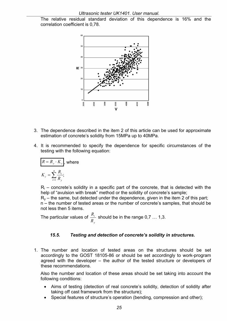
2. The universal calibration dependence should be built for specific regions after summarized Data processing, that was used for building the calibration dependences for single building objects. On the picture is represented the calibration dependence, that was based on the summarizing of data from the testing of seventeen monolithic structures in Moscow. The concrete of about 28-day age was tested on solidity. The dependence will be the following:
3,27016,0 −⋅= VRу
Ultrasonic tester UK1401. User manual.
25
The relative residual standard deviation of this dependence is 16% and the correlation coefficient is 0,78.
3. The dependence described in the item 2 of this article can be used for approximate estimation of concrete’s solidity from 15MPa up to 40MPa.
4. It is recommended to specify the dependence for specific circumstances of the testing with the following equation:
cу KRR ⋅= , where
;1
∑=
=n
i y
ic R
RK
Ri – concrete’s solidity in a specific part of the concrete, that is detected with the help of “avulsion with break” method or the solidity of concrete’s sample; Ry – the same, but detected under the dependence, given in the item 2 of this part; n – the number of tested areas or the number of concrete’s samples, that should be not less then 5 items.
The particular values of y
i
RR should be in the range 0,7 … 1,3.
15.5. Testing and detection of concrete’s solidity in structures.
1. The number and location of tested areas on the structures should be set
accordingly to the GOST 18105-86 or should be set accordingly to work-program agreed with the developer – the author of the tested structure or developers of these recommendations. Also the number and location of these areas should be set taking into account the following conditions:
• Aims of testing (detection of real concrete’s solidity, detection of solidity after taking off cast framework from the structure);
• Special features of structure’s operation (bending, compression and other);
Ultrasonic tester UK1401. User manual.
26
• Conditions of testing; • Type of structure’s reinforcement; • Availability or absence of testing sample cubes.
2. The velocity (time) of ultrasound dissemination on each area subjected to testing is made at least two times. The deviation of single measurements from the single average should meet the requirements, described in the item 7 of “Preparations for testing”. The concrete’s solidity is detected by the average meaning of received ultrasound velocity (time). When choosing the locations of areas subjected to testing you need to take into consideration item 6 of “Preparations for Testing”.
3. When testing the solidity of concrete structures in which the concrete is up to 56-day old the structure’s age should not differ from the average age of samples or testing areas, used for building the calibration dependence, on more then 25%. When testing the solidity of older concrete this difference should not exceed the range of parts’ or sample’s ages that were used for building calibration dependence. To detect concrete’s solidity in explotable structures it is necessary to use the calibration dependence that is built right before the testing.
4. The concrete’s solidity of structure’s tested area is detected by the calibration dependence that is built accordingly to the part “Preparation for Testing”. The measured ultrasound velocity (time) should lie between the minimal and maximal meanings of ultrasound velocity in samples or parts of structures that were used for building calibration dependence. The received values of concrete’s velocity are taken for average solidity of concrete of Ri part of structure.
5. For detection of concrete’s type (class) based on the results of testing, you need to use GOST 18105-86 requirements.
For more information and explanation for these recommendations, please contact Acoustic Control Systems Ltd. 119048, Moscow, POBox 148 tel/fax +7 095 244-3194, 244-2535, 245-5896 e-mail [email protected] website www.acsys.ru
Ultrasonic tester UK1401. User manual.
27
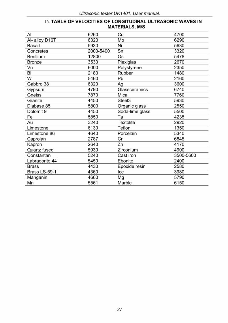
16. TABLE OF VELOCITIES OF LONGITUDINAL ULTRASONIC WAVES IN MATERIALS, M/S
Al 6260 Cu 4700 Al- alloy D16T 6320 Мо 6290 Basalt 5930 Ni 5630 Concretes 2000-5400 Sn 3320 Berillium 12800 Os 5478 Bronze 3530 Plexiglas 2670 Vn 6000 Polystyrene 2350 Вi 2180 Rubber 1480 W 5460 Pb 2160 Gabbro 38 6320 Ag 3600 Gypsum 4790 Glassceramics 6740 Gneiss 7870 Mica 7760 Granite 4450 Steel3 5930 Diabase 85 5800 Organic glass 2550 Dolomit 9 4450 Soda-lime glass 5500 Fe 5850 Та 4235 Au 3240 Textolite 2920 Limestone 6130 Teflon 1350 Limestone 86 4640 Porcelain 5340 Caprolan 2787 Cr 6845 Kapron 2640 Zn 4170 Quartz fused 5930 Zirconium 4900 Constantan 5240 Cast iron 3500-5600 Labradorite 44 5450 Ebonite 2400 Brass 4430 Epoxide resin 2580 Brass LS-59-1 4360 Ice 3980 Manganin 4660 Мg 5790 Мn 5561 Marble 6150