ultrasonic wave propagation in … industry, 2-6-1 nagasaka, ... presentation of the dynamic ray...
TRANSCRIPT

ULTRASONIC WAVE PROPAGATION IN
DISSIMILAR METAL WELDS – APPLICATION OF
A RAY-BASED MODEL AND COMPARISON
WITH EXPERIMENTAL RESULTS
11th ECNDT | October 6-10, 2014, Prague
Audrey GARDAHAUT1, Hugues LOURME1, Frédéric JENSON1, Shan LIN2, Masaki NAGAI2
1 CEA – LIST, Digiteo Labs, Bât. 565, PC 120, 91191 Gif-sur-Yvette, France.2 Materials Science Research Laboratory, Central Research Institute of Electric Power Industry, 2-6-1 Nagasaka, Yokohama-shi, Kanagawa-ken 240-0196, Japan.

CONTEXT & OBJECTIVES OF THE STUDY
Nondestructive testing inside or in the vicinity of weldsPhysical properties of Dissimilar Metal Welds – Input data of the model
SIMULATION OF WAVE PROPAGATION IN CIVA SOFTWARE
Presentation of the Dynamic Ray Tracing modelDescription of the DMWs
COMPARISON OF EXPERIMENTS AND SIMULATED RESULTS
Ultrasonic wave propagationUltrasonic inspection
CONCLUSION & PERSPECTIVES
11th ECNDT 2014 | Tuesday 7, 2014 | 2
OUTLINE

11th ECNDT 2014 | Tuesday 7, 2014 | 3
CONTEXT AND OBJECTIVES OF THE STUDY (1/2)
NONDESTRUCTIVE TESTING FOR THE DETECTION OF DEFECTS IN DMWs
Dissimilar Metal Welds (DMWs)
Connection between stainless steel cooling pipes and ferritic steel vessels
Ultrasonic inspection to prevent leaks appearance in primary circuitAffected by the anisotropy and inhomogeneity of the structuresObservation of beam splitting and skewingBeam attenuation along the propagation in such media
Simulation of inspection with CIVAImprovement of the understanding of physical phenomena involved in UT inspectionEvaluation of phased array techniques capacities
Macrograph of a DMW

V-butt Dissimilar Metal Welds
Studied weld made of alloy 600
Anisotropy of the weld materialFrom the literature: Alloy grade with elastic constants representative of the anisotropy of the weld*B. CHASSIGNOLE et al., JRC-NDE 2009.
Attenuation coefficient in the materialFrom the literature: experimental evaluation at 2 MHz in 316L in function of the
constitutive grain orientation from the incident beam*B. CHASSIGNOLE et al., JRC-NDE 2009.
11th ECNDT 2014 | Tuesday 7, 2014 | 4
CONTEXT & OBJECTIVES OF THE STUDY (2/2)
PHYSICAL PROPERTIES OF DISSIMILAR METAL WELDS – INPUT DATA OF THE MODEL
Macrograph of a DMW
(in GPa) C11 C22 C33 C23 C13 C12 C44 C55 C66 ρ (kg.m-3)
Alloy 182 * 255.8 255.8 236 135.4 137.9 130.5 111.4 111.9 81.4 8260
0° 15° 30° 45° 60° 75° 90°
Attenuation
(in dB/mm) *0.037 0.036 0.048 0.068 0.087 0.115 0.175

SIMULATION OF THE WAVE PROPAGATION
IN CIVA SOFTWARE

Ray-based model → search of asymptotic solutions of the elastodynamic equation
V. ČERVENÝ, Seismic Ray Theory, Cambridge University Press, 2001.
A. GARDAHAUT et al., AIP Conference Proceedings, Vol. 1581, 2014.
Based on the solving of two equations in anisotropic inhomogeneous mediumThe eikonal equation → evaluation of the ray-paths and travel time
The transport equation → computation of the ray amplitude
11th ECNDT 2014 | Tuesday 7, 2014 | 6
PROPAGATION MODEL IN CIVA (1/2)
DYNAMIC RAY TRACING (DRT) MODEL – THEORY
Polarization vectorChristoffel tensor
Eigenvalues of the Christoffel tensor
Density of the medium
S
M
Wave amplitudeEnergy velocity vector

Model adapted to the study of anisotropic and inhomogeneous media
Continuous variable description of the medium taken as input dataVariations of the elastic constants taken into account
Accurate computation of the ray amplitude by taking into account the physical properties of the inhomogeneous mediumEvaluation of the interface crossing between two inhomogeneous media
Limits of the DRT modelModel based on a high-frequency approximation → Need to have a medium description varying slowly with respect to the characteristic length such as the wavelength
11th ECNDT 2014 | Tuesday 7, 2014 | 7
PROPAGATION MODEL IN CIVA (2/2)
SUPPLY AND LIMITS OF THE DYNAMIC RAY TRACING (DRT) MODEL
CIVA 11 model adapted
to anisotropic
homogeneous media
→ straight trajectory
DRT model adapted to
anisotropic
inhomogeneous media
(CIVA development)
→ curved trajectory

Dynamic Ray Tracing model
Expression of the inhomogeneity through the crystallographic orientation variations
Analytical description of the grain orientationJ.A. OGILVY, ‘Computerized ultrasonic ray tracing in austenitic steel’, NDT International, vol. 18(2), 1985.
Description of the considered weld in the model
11th ECNDT 2014 | Tuesday 7, 2014 | 8
DESCRIPTION OF THE DISSIMILAR METAL WELDS
INPUT DATA OF THE MODEL
Buttering
78°Weld parameters:

ULTRASONIC WAVE PROPAGATION

Measurement method
Transmitters: 2 MHz angle beam transducers located on the top surface (L49° and S45°)Receiver: 2 MHz normal incidence transducer on the side surface of the specimen (ϕ = 1 mm)
Scanning direction:35 mm along x direction and 80 mm along y directionresolution 0.2 mm on the side surface
Aim of the experimentMeasurement of the propagation of longitudinal and shear wave in the weldObservation of the wave front at any time during the propagationComparison with corresponding simulations
11th ECNDT 2014 | Tuesday 7, 2014 | 10
ULTRASONIC BEAM MEASUREMENT
PRESENTATION OF THE EXPERIMENTAL SET-UP
①Transmitter (Angle beam transducer)
②Receiver ( Normal incidence transducer)
③Scanning area
(0, 0)x
y
・Data acquisition
・ Scanner control
・Wave viewer ①③
②
Tes
tin
g su
rfac
e
Sid
esu
rfac
e

Emission of L49° wave on the buttering – Propagation from the ferritic to the stainless steel
→ Deviation of the beam during the propagation in the weld (inhomogeneous properties)
→ Good agreement of the simulation with experiment at each time step→ No simulation of the scattering of the shear wave during the propagation
11th ECNDT 2014 | Tuesday 7, 2014 | 11
OBSERVATION OF THE WAVE PROPAGATION (1/2)
COMPARISON OF SIMULATED RESULTS AND EXPERIMENTS
Incident point (80, 40)
X
Y55
T T + 4 ms T + 9 ms
Experi
ment
CIV
A s
imula
tion
Simulated beam

Emission of L49° wave on the weld – Propagation from the stainless to the ferritic steel
→ Deviation of the beam during the propagation in the weld (inhomogeneous medium)
→ Slight differences of the position of the maximum of the wave front→ No simulation of the scattering of the shear wave during its propagation in the weld
11th ECNDT 2014 | Tuesday 7, 2014 | 12
OBSERVATION OF THE WAVE PROPAGATION (2/2)
COMPARISON OF SIMULATED RESULTS AND EXPERIMENTS
Incident point (80, 40)
Y
60
XT T + 3 ms T + 6 ms
Experi
ment
CIV
A s
imula
tion
Simulated beam

Good agreement between the experimental measurement and the simulation of the wave
propagation in the DMW described thanks to a closed-form
Observation of the beam deviation due to the evaluation of the rays trajectory in an
anisotropic inhomogeneous medium (take into account of the elastic constants variations)
Good location of the wave front at each time step
Observation of slight differences of the position of the maximal amplitude Due to the straight separation between the physical properties of the weld and the
buttering
Absence of the visualization of the beam perturbation during its propagation in the weld
No simulation of the scattering of the shear beam due to the constitutive grains of
the Dissimilar Metal Weld
11th ECNDT 2014 | Tuesday 7, 2014 | 13
ULTRASONIC EXAMINATION
CONCLUSION OF THE BEAM COMPARISON

ULTRASONIC INSPECTION

Searched defects
Three 10 mm height notchesIn the buttering, the weld and the stainless steel
Probe1 MHz linear array transducer64 elementsPitch = 0.6 mm, length = 0.5 mmFocusing at 20 mm (halfway through the thickness)
EmissionL- waveNominal refraction angle 49°Pulse-echo technique
Aim of the experimentDetection of the tip diffraction and corner echoes of each defectS3 notch on the stainless steel chosen as the reference defectComparison with corresponding simulations
11th ECNDT 2014 | Tuesday 7, 2014 | 15
ULTRASONIC INSPECTION OF DMWs
PRESENTATION OF THE EXPERIMENTAL SET-UP
S1
S2
S3
Ferritic SteelStainless Steel
Weld
Buttering

Propagation from the ferritic to the stainless steel
Notch in the weld
Experi
ment
T
C
Simulatio
n
C
T
Notch in the weld
T
C
Experi
ment
C
T
Simulatio
n
11th ECNDT 2014 | Tuesday 7, 2014 | 16
NOTCH DETECTION (1/2)
COMPARISON OF SIMULATED RESULTS AND EXPERIMENTS
-12.2 dB
-5.6 dB
-10.1 dB
-2.0 dB
-6.3 dB-5.8 dB
-2.4 dB-1.6 dB
→ Good detection of the tip diffraction and corner echoes of both notches in experiment
→ Good reproduction of these responses in CIVA simulation
→ Very good agreement of the values of the echoes between experiment and simulation
→ Maximal difference of 3.6 dB for the less favorable configuration where the wave travels through the whole welded zone
Noise in the medium and boundary echoes not taken into account

T
C
C
T
Notch in the weld
Sim
ulat
ion
Expe
rim
ent
Notch in the buttering
T
C
C
T
Sim
ulat
ion
Expe
rim
ent
C
T
Notch in the weld
Experi
ment Sim
ulatio
n
Propagation from the stainless to the ferritic steel
T
C
C
T
Notch in the weld
Experi
ment Sim
ulatio
n
11th ECNDT 2014 | Tuesday 7, 2014 | 17
NOTCH DETECTION (2/2)
COMPARISON OF SIMULATED RESULTS AND EXPERIMENTS
-14.2 dB
-11.3 dB-8.9 dB
-5.7 dB
→ Less easier detection of the notches in experiment in this configuration: appearance of noise caused by the internal structure of the weld
→ Good detection of the two notches in CIVA simulation
→ Good agreement of the echoes values between experiment and simulation
→ Slight differences for the corner echoes due to the propagation in a zone where the crystallographic orientation varies importantly
Noise in the medium and boundary echoes not taken into account
-7.0 dB
-5.1 dB-3.5 dB
-4.2 dB

CONCLUSION & PERSPECTIVES

Study of Dissimilar Metal Welds
Representation of the inhomogeneity of the medium through a description of the crystallographic orientation inside a V-butt weld made of alloy 600
Propagation modelDynamic Ray Tracing model for the evaluation of the wave propagation in anisotropic inhomogeneous media
Ultrasonic beamComparison of experiments and simulationsGood evaluation of the ultrasonic wave field in complex structures such as DMWs
Ultrasonic inspectionComparison of the defect response: simulation/experimentsGood detection of notches in the weld or in the buttering
Good evaluation of the amplitude of the response
11th ECNDT 2014 | Tuesday 7, 2014 | 19
CONCLUSION OF THE STUDY (1/2)
CONCLUSION

Improvement of the description of the DMWs
Description of the whole weld (welded zone + buttering) with a continuously variable description of the crystallographic orientation→ To avoid creation of straight separation between two media
Improvement of the model
Adaptation of the defect response model implemented in CIVA to the detection of defect located in a smoothly inhomogeneous medium→ Take into account of the variations of the physical properties along the edges of the considered defect
11th ECNDT 2014 | Tuesday 7, 2014 | 20
CONCLUSION OF THE STUDY (2/2)
PERSPECTIVES
Example of an analytical law Macrograph of the DMW

DRT
LIST / DISC
LMC
Commissariat à l’énergie atomique et aux énergies alternatives
Institut Carnot CEA LIST
Centre de Saclay | 91191 Gif-sur-Yvette Cedex
T. +33 (0)1 69 08 40 26 | F. +33 (0)1 69 08 75 97
Etablissement public à caractère industriel et commercial | RCS Paris B 775 685 019
THANK YOU FOR YOUR ATTENTION !

Ray-based model → search of asymptotic solutions of the elastodynamic equation
V. Červený, Seismic Ray Theory, Cambridge University Press, 2001.
Evaluation of ray paths and travel timeEikonal equation in anisotropic inhomogeneous medium:
Obtaining of a system of ordinary differential equations: the axial ray system
11th ECNDT 2014 | Tuesday 7, 2014 | 22
SIMULATION OF WAVE PROPAGATION IN CIVA (1/2)
THE DYNAMIC RAY TRACING (DRT) MODEL
Elasticity constants
Energy velocity vector
Slowness vector
Polarization vectorChristoffel tensor
Eigenvalues of the Christoffel tensor
Existence of three eigenvalues associated to three
eigenvectors of the matrix representing the
three plane waves that propagate in the medium
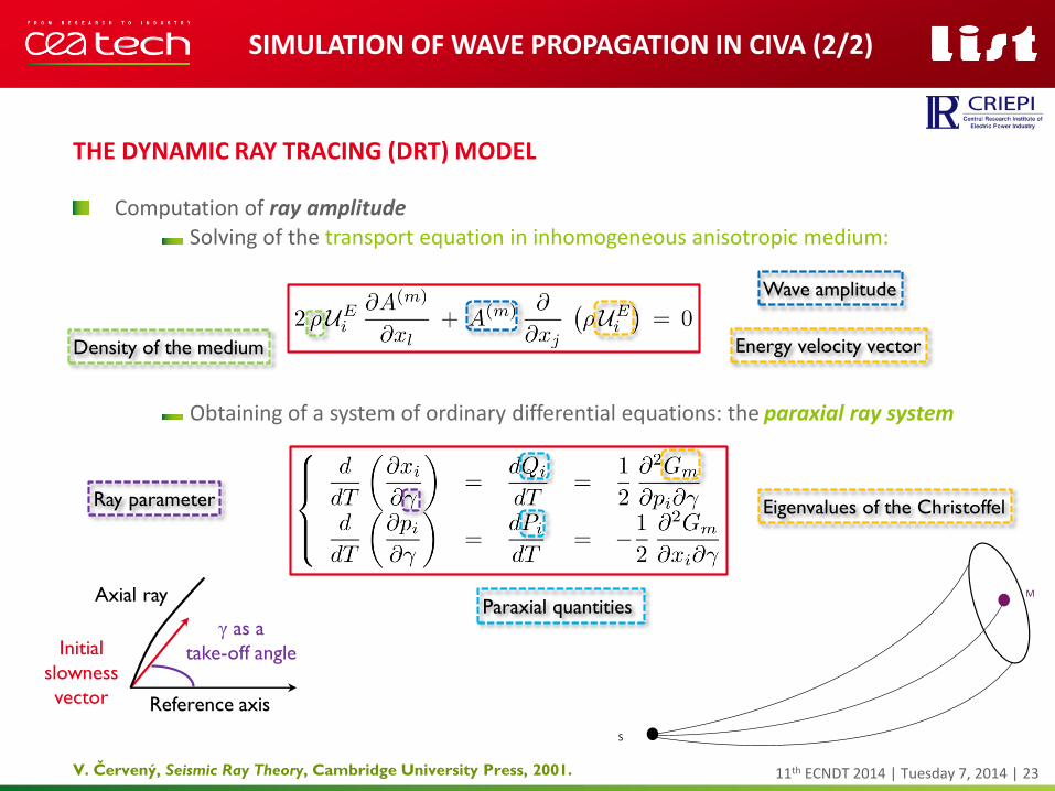
Computation of ray amplitude
Solving of the transport equation in inhomogeneous anisotropic medium:
Obtaining of a system of ordinary differential equations: the paraxial ray system
11th ECNDT 2014 | Tuesday 7, 2014 | 23
SIMULATION OF WAVE PROPAGATION IN CIVA (2/2)
THE DYNAMIC RAY TRACING (DRT) MODEL
V. Červený, Seismic Ray Theory, Cambridge University Press, 2001.
Axial ray
Initial
slowness
vector
γ as a
take-off angle
Reference axis
Ray parameter
Paraxial quantities
Eigenvalues of the Christoffel
Density of the medium Energy velocity vector
Wave amplitude
S
M