um zip52 finishing pf zzb012 - wagner group · zip52 finishing - pf . operating manual edition 01...
TRANSCRIPT

II 2G IIB T4
ZIP 52 FINISHING
ZIP 52 PF
Diaphragms pump
ZIP52 ALU SPZIP 52 INOX SPZIP 52 ACETAL SPZIP 52 PERFECT FLOW SP
Edition 01 / 2010
Translation of the original
Operating Manual


3
ZIP52 FINISHING - PF .
OPERATING MANUAL
EDITION 01 /2010 PART NO. ZZB012ENG
Contents
1 ABOUT THESE INSTRUCTIONS 51.1 Languages 51.2 Warnings, notes and symbols in these instructions 5
2 GENERAL SAFETY INSTRUCTIONS 62.1 Safety instructions for the operator 62.1.1 Electrical equipment 62.1.2 Personnel qualifi cations 62.1.3 A safe work environment 62.2 Safety instructions for staff 62.2.1 Safe handling of WAGNER spray units 72.2.2 Earth the unit 72.2.3 Material hoses 72.2.4 Cleaning 82.2.5 Handling hazardous liquids, varnishes and paints 82.2.6 Touching hot surfaces 82.3 Correct use 82.4 Use in an explosion hazard area 92.4.1 Correct use 92.4.2 Explosion protection identifi cation 92.4.3 Max. surface temperature 92.4.4 Safety regulations 9
3 PRODUCT LIABILITY AND WARRANTY (STATUS 01.02.2009) 11
3.1 Scope of guarantee 113.2 Guarantee period and registration (3+2) 113.3 Handling 113.4 Exclusion of guarantee 123.5 Additional regulations 123.6 CE-conformity 13
4 DESCRIPTION 144.1 Field of application 144.1.1 Using in accordance with the instructions 144.2 Extent of delivery 144.3 Data 144.3.1 Materials of the parts transporting paint 144.3.2 technical data 154.3.3 Dimensions and connections 164.4 Functioning 184.4.1 Pump 184.4.2 Pressure regulator 194.4.2.1 Technical sheet fi ne fl ow controller cod. 2301832, 2301836, 2301837 20
5 STARTING UP AND OPERATING 215.1 Installation and connection 215.1.1 Pump installation 215.1.2 Earthing 225.2 Start up 24

4
ZIP52 FINISHING - PF .
OPERATING MANUAL
EDITION 01 /2010 PART NO. ZZB012ENG
Contents5.2.1 Safety regulations 245.2.2 Emergency stopping 255.2.3 Washing 265.2.4 Unit pressure tightness test 265.3 Work 275.3.1 Spraying 275.3.2 Painting hints 285.3.3 Working breaks 285.3.4 Shutting down and cleaning 295.4 Storing for longer periods of time 29
6 FAULT LOCATION, MAINTENANCE AND REPAIR 306.1 Trouble shooting and solution 306.2 Maintenance 316.3 Filter cleaning operations 326.4 Machine maintenance 33
7 ACCESSORIES 357.1 Accessories only for 2301832, 2301836, 2301837 357.2 Pump zip 52 fi nishing with wall supporting kit cod. T760.00M 367.2.1 Overall dimensions cod. T760.00M 377.3 Pump zip 52 fi nishing with stand kit cod. T760.00S 387.3.1 Overall dimensions cod. T760.00S 397.4 Pump zip 52 fi nishing with handle+wheels kit cod. T760.00R for stand pumps cod. T760.00S 407.4.1 Overall dimensions cod. T760.00R 417.5 Pompa zip 52 fi nishing with trolley kit cod. T760.00SR 427.5.1 Overall dimensions cod. T760.00SR 43
8 SPARE PARTS 448.1 How to order spare parts 448.2 Overview modules 468.3 Exploded view 478.3.1 Pump cod. 2301832, 2301836, 2301837 478.3.2 Pump cod. 2301838 508.3.3 Pump ZIP 52 538.3.4 Air motor pump ZIP52 558.3.5 Fine fl ow controller T0180.00A, T0180.00AI 578.3.6 Material fi lter 1/2 aluminium cod. T4005.00ALS (for 2301838) 598.3.7 Suction pipe + re-cycle pipe cod. T406.00, T406.00A 61
9 EUROPEAN SERVICE NETWORK 65

5
ZIP52 FINISHING - PF .
OPERATING MANUAL
EDITION 01 /2010 PART NO. ZZB012ENG
1.2 WARNINGS, NOTES AND SYMBOLS IN THESE INSTRUCTIONS
1 ABOUT THESE INSTRUCTIONS
1.1 LANGUAGES
ZZB012GER ZZB012ENG ZZB012FRE -- ZZB012ITA -- -- -- -- --

6
ZIP52 FINISHING - PF .
OPERATING MANUAL
EDITION 01 /2010 PART NO. ZZB012ENG
2 GENERAL SAFETY INSTRUCTIONS
2.1 SAFETY INSTRUCTIONS FOR THE OPERATOR
2.1.1 ELECTRICAL EQUIPMENT
2.1.2 PERSONNEL QUALIFICATIONS
2.1.3 A SAFE WORK ENVIRONMENT
2.2 SAFETY INSTRUCTIONS FOR STAFF
Ensure that the floor of the working area is anti-static in accordance with EN 50053 Part 1§7-2.Ensure that all persons within the working area wear anti-static shoes, e.g. shoes withleather soles.Ensure that during spraying, persons wear anti-static gloves so that they are earthed viathe handle of the spray gun.Customer to provide paint mist extraction systems conforming to local regulations.Ensure that the following components of a safe working environment are available:– Material/air hoses adapted to the working pressure– Personal safety equipment (breathing and skin protection)Ensure that there are no ignition sources such as naked flame, glowing wires or hotsurfaces in the vicinity. Do not smoke.

7
ZIP52 FINISHING - PF .
OPERATING MANUAL
EDITION 01 /2010 PART NO. ZZB012ENG
2.2.1 SAFE HANDLING OF WAGNER SPRAY UNITS
2.2.2 EARTH THE UNIT
2.2.3 MATERIAL HOSES
The spray jet is under pressure and can cause dangerous injuries.Avoid injection of paint or cleaning agents:
Never point the spray gun at people.Never reach into the spray jet. Before all work on the unit, in the event of work interruptions and functionalfaults:– Switch off the energy/compressed air supply – Secure the spray gun against actuation.– Relieve the pressure from the spray gun and unit. – By functional faults: If possible, remove the defect as described in
chap. „Trouble shooting“, otherwise apply to an authorised after-sale service point.In the event of skin injuries caused by paint or cleaning agents:
Note down the paint or cleaning agent that you have been using.Consult a doctor immediately.
Avoid danger of injury through recoil forces:Ensure that you have a firm footing when operating the spray gun. Only hold the spray gun briefly in any one position.
Electrostatic charges can occur on the unit due to the electrostatic charge and the flowspeed involved in spraying.These can cause sparks and flames upon discharge.
Ensure that the unit is earthed for every spraying operation.Earth the workpieces to be coated.Ensure that all persons inside the working area are earthed, e.g. that they are wearingantistatic shoes.When spraying, wear antistatic shoes to earth yourself via the spray gun handle.If gloves are used, they must be antistatic
8
ZIP52 FINISHING - PF .
OPERATING MANUAL
EDITION 01 /2010 PART NO. ZZB012ENG
2.2.4 CLEANING
2.2.5 HANDLING HAZARDOUS LIQUIDS, VARNISHES AND PAINTS
2.2.6 TOUCHING HOT SURFACES
2.3 CORRECT USE

9
ZIP52 FINISHING - PF .
OPERATING MANUAL
EDITION 01 /2010 PART NO. ZZB012ENG
2.4.1 CORRECT USE
2.4.2 EXPLOSION PROTECTION IDENTIFICATION
2.4.3 MAX. SURFACE TEMPERATURE
2.4.4 SAFETY REGULATIONS
2.4 USE IN AN EXPLOSION HAZARD AREA
As defined in the Directive 94/9/CE (ATEX 95), the unit is suitable for use in areas wherethere is an explosion hazard.
II 2G IIB T4CE: Communautés EuropéennesEx: Symbol for explosion protectionII: Unit class II 2: Category 2 (Zone 1) G: Ex-atmosphere gas IIB: Explosion class T4: Temperature class: maximum surface temperature < 135°C; 275°F.
Max. surface temperature: same as the permissible material temperaturePermissible ambient temperature: see under Technical data, Section 4.3.2

10
ZIP52 FINISHING - PF .
OPERATING MANUAL
EDITION 01 /2010 PART NO. ZZB012ENG

11
ZIP52 FINISHING - PF .
OPERATING MANUAL
EDITION 01 /2010 PART NO. ZZB012ENG
3 PRODUCT LIABILITY AND WARRANTY (STATUS 01.02.2009)
3.1 SCOPE OF GUARANTEE
3.2 GUARANTEE PERIOD AND REGISTRATION (3+2)
All Wagner professional colour application devices (hereafter referred to as products) are carefully inspected, tested and are subject to strict checks under Wagner quality assurance. Wagner exclusively issues extended guarantees to commercial or professional users (he-reafter referred to as “customer”) who have purchased the product in an authorised spe-cialist shop, and which relate to the products listed for that customer on the Internet under www.wagner-group.com/profi -guarantee. The buyer’s claim for liability for defects from the purchase agreement with the seller as well as statutory rights are not impaired by this guarantee. We provide a guarantee in that we decide whether to replace or repair the product or individual parts, or take the device back and reimburse the purchase price. The costs for materials and working hours are our responsibility. Replaced products or parts become our property.
The guarantee period amounts to 36 months. For industrial use or equal wear, such as shift operations in particular, or in the event of rentals it amounts to 12 months.Systems driven by petrol or air are also guaranteed for a 12 month period. The guarantee period begins with the day of delivery by the authorised specialist shop. The date on the original purchase document is authoritative. For all products bought in authorised specialist shops from 01.02.2009 the guarantee pe-riod is extended to 24 months providing the buyer of these devices registers in accordan-ce with the following conditions within 4 weeks of the day of delivery by the authorised specialist shop. Registration can be completed on the Internet under www.wagner-group.com/profi -gua-rantee. The guarantee certifi cate is valid as confi rmation, as is the original purchase docu-ment that carries the date of the purchase. Registration is only possible if the buyer is in agreement with having the data being stored that is entered during registration. When services are carried out under guarantee the guarantee period for the product is neither extended nor renewed. Once the guarantee period has expired, claims made against the guarantee or from the guarantee can no longer be enforced.
3.3 HANDLING
If defects can be seen in the materials, processing or performance of the device during the guarantee period, guarantee claims must be made immediately, or at the latest within a period of 2 weeks. The authorised specialist shop that delivered the device is entitled to accept guarantee claims. Guarantee claims may also be made to the service centres named in our operating instructions. The product has to be sent without charge or presented together with the original purchase document that includes details of the purchase date and the name of the product. In order to claim for an extension to the guarantee, the guarantee certifi cate must be included. The costs as well as the risk of loss or damage to the product in transit or by the centre that accepts the guarantee claims or who delivers the repaired product, are the responsibility of the customer.

12
ZIP52 FINISHING - PF .
OPERATING MANUAL
EDITION 01 /2010 PART NO. ZZB012ENG
3.4 EXCLUSION OF GUARANTEEGuarantee claims cannot be considered - for parts that are subject to wear and tear due to use or other natural wear and tear, as well as defects in the product that are a result of natural wear and tear, or wear and tear due to use. This includes in particular cables, valves, packaging, jets, cylinders, pistons, means-carrying housing components, fi lters, pipes, seals, rotors, stators, etc. Damage due to wear and tear that is caused in particular by sanded coating materials, such as dispersions, pla-ster, putty, adhesives, glazes, quartz foundation. - in the event of errors in devices that are due to non-compliance with the operating in-structions, unsuitable or unprofessional use, incorrect assembly and/or commissioning by the buyer or by a third party, or utilisation other than is intended, abnormal ambient con-ditions, unsuitable coating materials, unsuitable operating conditions, operation with the incorrect mains voltage supply/frequency, over-operation or defective servicing or care and/or cleaning.- for errors in the device that have been caused by using accessory parts, additional com-ponents or spare parts that are not original Wagner parts. - for products to which modifi cations or additions have been carried out. - for products where the serial number has been removed or is illegible - for products to which attempts at repairs have been carried out by unauthorised per-sons. - for products with slight deviations from the target properties, which are negligible with regard to the value and usability of the device. - for products that have been partially or fully taken apart.
3.5 ADDITIONAL REGULATIONS
The above guarantees apply exclusively to products that have been bought by authorised specialist shops in the EU, CIS, Australia and are used within the reference country.
If the check shows that the case is not a guarantee case, repairs are carried out at the expense of the buyer.
The above regulations manage the legal relationship to us concludingly. Additional claims, in particular for damages and losses of any type, which occur as a result of the product or its use, are excluded from the product liability act except with regard to the area of appli-cation.
Claims for liability for defects to the specialist trader remain unaffected. German law applies to this guarantee. The contractual language is German. In the event that the meaning of the German and a foreign text of this guarantee deviate from one another, the meaning of the German text has priority.
J. Wagner GmbHDivision Professional FinishingOtto Lilienthal Strasse 18 88677 MarkdorfFederal Republic of Germany

13
ZIP52 FINISHING - PF .
II 2G IIB T4
2301832
2301836
2301837
2301838
OPERATING MANUAL
EDITION 01 /2010 PART NO. ZZB012ENG
3.6 CE-CONFORMITY
Herewith we declare that the supplied version of:Pneumatic pumps with article no.
Complies with the following provisons applying to it:
2006/42/EC 94/9/EC Atex
Applied standards, in particular:
UNI EN 12100-1 UNI EN 809 UNI EN 1127-1
UNI EN 12100-2 UNI EN ISO 14121-1 EN 12621
UNI EN 563 UNI EN ISO 3746 UNI EN ISO 13463
Marking:
ZDI.20

14
ZIP52 FINISHING - PF .
OPERATING MANUAL
EDITION 01 /2010 PART NO. ZZB012ENG
4 DESCRIPTION
4.1 FIELD OF APPLICATION
4.1.1 USING IN ACCORDANCE WITH THE INSTRUCTIONS
The pneumatic diaphragm pump is suitable for process liquid materials.
SIHC_0067_GB
CAUTIONAbrasive fluids and pigments !Greater wear of the parts carrying the material.
Use suitable pump model (delivery per cycle, material, valves, etc.)see chapter 4.3.2.
Verify that fluids and solvents used are compatible with the constrution material of the pump as described in chapter 4.3.1.
4.2 EXTENT OF DELIVERY
Pneumatic diaphragm pump consisting of:
- Material pump / Air motor- Material regulator/Antipulsator and/or fi lter- Support pump with regulators- Suction hose- Connections
CE-conformity see Chapter 3Operating manual in english Part No. : ZZB012ENGOperating manual for the other language see Chapter 1
The delivery note shows the exact scope of delivery.Accessories: see chapter 7.
4.3 DATA
4.3.1 MATERIALS OF THE PARTS TRANSPORTING PAINT
2301832 2301836 2301837 2301838
Covers/Manifolds Aluminium Stainless steel Acetal Aluminium
Balls Stainless steel Stainless steel Stainless steel Stainless steel
Valve seats Stainless steel Stainless steel Stainless steel Stainless steel
Diaphragms PE PE PE PE
Static gaskets (product side)
PTFE PTFE PTFE PTFE

15
ZIP52 FINISHING - PF .
OPERATING MANUAL
EDITION 01 /2010 PART NO. ZZB012ENG
4.3.2 TECHNICAL DATA
Description Units 2301832 2301836 2301837 2301838
Transmission ratio 1 :1 1 :1 1 :1 1 :1
Fluid max fl ow rate l/min 52 52 52 28
Max. operating pressure MPabarpsi
8116
1682
8116
1682
8116
1682
8116
1682
Min. - Max. air inlet pressure. MPabarpsi
0.1-0.81-8
15-116
0.1-0.81-8
15-116
0.1-0.81-8
15-116
0.1-0.81-8
15-116
Ø air inlet connection (female) BSP 1/4“ 1/4“ 1/4“ 1/4“
Sound power at max. fl ow ratefeeding 8 bar; 116 psi *.
dB(A) 99 99 97 99
Sound pressure equivalent to max.fl ow ratefeeding 8 bar; 116 psi *.
dB(A) 85 85 85 85
Sound pressure equivalent to 50 cycles/min feeding 5 bar; 72,5 psi*.
dB(A) 76 76 73 76
Material outlet connection (female) (M16x1,5) Inch G 1/4“ G 1/4“ G 1/4“ G 1/4“
Weight kg lb
3.88.4
6.113.4
2.96.4
3.88.4
Max. material pressure at pump inlet MPabarpsi
0,11
14,5
0,11
14,5
Range of material temperature °C; F +4° ÷ +40°; (+39 ÷ +104) +4° ÷ +90°; (+39 ÷ +176)
Range of the ambient temperature °C; F +4° ÷ +40°; (+39 ÷ +104)
Allowable sloping position at work <) ° ± 10
* A rated sound pressure level measured at 1m distance according to UNI EN ISO 3744.

16
ZIP52 FINISHING - PF .
AB
C DE
F
G
H
J
K L
R
Q
F
I
SS
OPERATING MANUAL
EDITION 01 /2010 PART NO. ZZB012ENG
4.3.3 DIMENSIONS AND CONNECTIONS

17
ZIP52 FINISHING - PF .
2301832mm; inch
2301836mm; inch
2301837mm; inch
2301838mm; inch
2301832mm; inch
2301836mm; inch
2301837mm; inch
2301838mm; inch
A 295; 11,6 295; 11,6 280; 11 - M ø9; ø0.35 ø9; ø0.35 ø9; ø0.35 -B 280; 11 280; 11 280; 11 - N 38.3; 1.5 38.3; 1.5 38.3; 1.5 -C 189; 7,44 189; 7,44 189; 7,44 - O 80; 3.2 80; 3.2 80; 3.2 -D ø9; ø0.35 ø9; ø0.35 ø9; ø0.35 - P 189; 7.4 189; 7.4 189; 7.4 -E 360; 14,1 360; 14,1 360; 14,1 - Q - - - G1/4”F G1/4“ G1/4“ G1/4“ G1/4“ R - - - 940; 37G 158; 6,2 158; 6,2 158; 6,2 - S G1/4” G1/4” G1/4” -H ø16 ø16 ø16 - - - - - -I 250; 9,8 250; 9,8 260; 10,2 250; 9,8 - - - - -J 360; 14,1 - - - - -K 335; 13,1 - - - - -L 405; 15,9 - - - - -
C_00041
N
O
P
M
M
OPERATING MANUAL
EDITION 01 /2010 PART NO. ZZB012ENG
Mounting for wall for 2301832, 2301836,2301837

18
ZIP52 FINISHING - PF .
OPERATING MANUAL
EDITION 01 /2010 PART NO. ZZB012ENG
4.4 FUNCTIONING
4.4.1 PUMP
A DiaphragmsB Connecting shaftC Check valvesM Driving chambersP Pumping chambersQ Air motorR Inversion valve
General informationThe principle lying behind the functioning of diaphragm pumps driven by compressed air is just as simple as it is effective. Two diaphragms (A), which are connected to one another by means of a connecting shaft (B) so as to be integral, divide two adjacent capacities into four chambers. The inner ones function as driving chambers (M) while the outer ones func-tion as pumping, chambers (P). A pneumatic distributor alternately conveys compressed air into one of the driving chambers, thus producing the diaphragms movement and conse-quently causing one of the pumping chambers to empty (as a result of volume decrease), while at the same time the other fi lls up (as a result of volume increase). A series of check valves (C) prevents the liquid from fl owing back, thus producing the suction and delivery phases in each pumping chamber.
Air motor (Q)The pneumatic motor must be powered at a pressure not exceeding the value giv-en on the plate. Each component linked to the pump outlet must have an operat-ing pressure equal to or higher than the pressure generated by the pump itself.
This fi nal pressure is given onthe plate (see the picture on the right).

19
ZIP52 FINISHING - PF .
a b
c
def
g
h
i
l
OPERATING MANUAL
EDITION 01 /2010 PART NO. ZZB012ENG
4.4.2 PRESSURE REGULATOR
a Pump feeding air pressure reducerb Atomising air pressure reducerc Pump feeding air manometerd Atomising air manometere Atomising air connectionf Fluid suction pipeg Filter materialh Compressed air connectioni Fluid delivery connectionl Recycling valve
a Antipulsation Reducer Filter with pneum.control (FINE FLOW CONTROLLER)b Atomising air pressure reducerc Atomising air connectiond Pump motor feeding air manometere Controlling air manometer of pneumatic paint pressure reducerf Atomising air manometerg Controlling air pressure reducer of pneumatic paint reducerh PM motor feeding air pressure reduceri On-off and feeding air inlet valvel Re-cycle on-off valvem Fluid suction pipen Fluid delivery connection
Figure: Pump 2301832, 2301836, 2301837
Figure: Pump 2301838

20
ZIP52 FINISHING - PF .
00,5
11,5
22,5
33,5
44,5
0 1 2Portata/Flow rate/Débit/Förderung [l/min.]
Pres
sion
e us
cita
/Out
let
pres
s./P
ress
.à la
so
rtie
/Aus
gang
sdru
ck [b
ar]
0
OPERATING MANUAL
EDITION 01 /2010 PART NO. ZZB012ENG
Part in contact with the productRegulator body:(p): Konsistal (for T0180.00A)Regulator body: (p): Stainless Stell (for T0180.00AI)
Antipulsation body (q): PPProduct diaphragm:: PTFEShutter ball: Stainless StellShutter seat:: Tungsten carbide
Reducer section performanceswith fl uids having a viscosity of 45 mPa.s (corresponding to about 20 s. Ford 4) Inlet pressure : 5 Bar
Max allowed fl uid temperature (°C): 40Max inlet pressure (Bar): 14Guiding air inlet max. pressure (Bar) 8Adjustment range (Bar) 0.5 ÷ 8Product inlet connection (BSP) 2x 1/4” Fem.Product outlet connection (BSP) 2x 1/4” Fem.Air inlet connection (BSP) 1/8” Fem.
FILTER CARTRIDGE - INCLUDED(Mesh) 100OPTIONAL (Mesh) 60 and 150 Dimensions Diameter (mm): 90Height (mm): 165weight (gr): 850 (for T0180.00A)weight (gr): 1455 (for T0180.00AI)
4.4.2.1 TECHNICAL SHEET FINE FLOW CONTROLLER COD. 2301832, 2301836, 2301837

21
ZIP52 FINISHING - PF .
OPERATING MANUAL
EDITION 01 /2010 PART NO. ZZB012ENG
5 STARTING UP AND OPERATING
5.1 INSTALLATION AND CONNECTION
5.1.1 PUMP INSTALLATION
NoteThe pneumatic motor must be supplied with clean industrial air; make sure effi cient fi ltering and con-densate separation systems are installed on the air line. All impurities and the eventual condensate that has built up inside the air fi lter on top of the pumpmust be drained daily.
NOTE: Consult specifi c catalogues when choosing the pipes. The driving air pipe must be properly di-mensioned.
Procedure for 2301832, 2301836, 2301837 :
1. Mount the pump onto a basement2. Connect the air atomization and paint delivery
hoses, respectively, to the corresponding attachments (C: air - N: paint), carefully tightening the fi ttings.
Procedure for 2301838 :
1. Connect the air to the pump in the (H) fi tting, installing an on-off valve on the line to stop the feeding air in case of emergency.
2. Connect the spraying air to its fi tting (E). Carry out the same operation for the paint delivery pipe, to be connected to its fi tting (I).

22
ZIP52 FINISHING - PF .
Ω
OPERATING MANUAL
EDITION 01 /2010 PART NO. ZZB012ENG
5.1.2 EARTHING
Earthing schema (example)
Paint container
Workpiece
Conveyor
Spraying stand
Anti-static fl oor

23
ZIP52 FINISHING - PF .
OPERATING MANUAL
EDITION 01 /2010 PART NO. ZZB012ENG
Cable cross sections
Pump 4 mm²; AWG 11
Paint container 6 mm²; AWG 10Conveyor 16 mm²; AWG 5Spraying booth 16 mm²; AWG 5Spraying stand 16 mm²; AWG 5
Procedure:
1. Screw on earthing cable with eye.2. Clamp the earthing cable clip to a earth connection
on site.3. Earth the material (paint) container to a local
earth connection.4. Earth the other parts of the system to a local earth
connection.

24
ZIP52 FINISHING - PF .
OPERATING MANUAL
EDITION 01 /2010 PART NO. ZZB012ENG
5.2 START UP
5.2.1 SAFETY REGULATIONS
Every time before starting up the following points should be observed as laid down in the operating instructions:
- That it is possible to observe the safety regulations in Chap. 2. - The starting up procedure, has been carried out properly.
25
ZIP52 FINISHING - PF .
OPERATING MANUAL
EDITION 01 /2010 PART NO. ZZB012ENG
5.2.2 EMERGENCY STOPPING
Before every start-up, the following points should be observed as laid down in the operating manual:
- If installed secure gun with safety catch - Check the permissible pressures - Check all connections for leaks - Check hose for damage
It should be ensured that the unit is in the following state before carrying out any work on it: - The pressure should be released from the pump and high-pressure hose with gun (if
installed). - The gun should be secured with safety catch (if installed). - The air supply should be interrupted
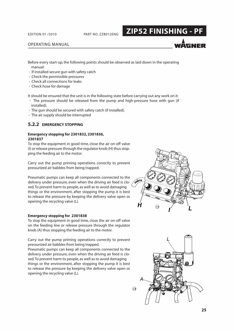
Emergency stopping for 2301832, 2301836, 2301837To stop the equipment in good time, close the air on-off valve (I) or release pressure through the regulator knob (H) thus stop-ping the feeding air to the motor.
Carry out the pump priming operations correctly to prevent pressurized air babbles from being trapped.
Pneumatic pumps can keep all components connected to the delivery under pressure, even when the driving air feed is clo-sed. To prevent harm to people, as well as to avoid damagingthings or the environment, after stopping the pump it is best to release the pressure by keeping the delivery valve open or opening the recycling valve (L).
Emergency stopping for 2301838To stop the equipment in good time, close the air on-off valve on the feeding line or release pressure through the regulator knob (A) thus stopping the feeding air to the motor.
Carry out the pump priming operations correctly to prevent pressurized air babbles from being trapped.Pneumatic pumps can keep all components connected to the delivery under pressure, even when the driving air feed is clo-sed. To prevent harm to people, as well as to avoid damagingthings or the environment, after stopping the pump it is best to release the pressure by keeping the delivery valve open or opening the recycling valve (L).

26
ZIP52 FINISHING - PF .
M
OPERATING MANUAL
EDITION 01 /2010 PART NO. ZZB012ENG
2301838
5.2.3 WASHING
5.2.4 UNIT PRESSURE TIGHTNESS TEST
2301832, 2301836, 2301837
The pump has been tested using mineral oil. Before using it, it is best to let it wash once using an adequate solvent. To do this, place the metallic side of the suction pipe (M) inside a container full of solvent.
Open the re-cycle valve (L).Make sure that the pressure regulator knob (H) is turned fully anti-clockwise (0 bar pressure). Open the air cutoff valve (I) (on the compressed air line for 2301838) and turn the motor air pres-sure regulator (H) knob clockwise until the pump starts. It is best to keep the atomization air valve (B) closed during washing ope-rations.
Set the motor air pressure to 2 bar.The pump sucks solvent and pours it back into the container through the re-cycle system, thus cleaning itself.Let the solvent fl ow inside the pump for 2 or 3 minutes.
NOTE: In case the pump does not start, check that the gauge (C) reads at least 2 bar, close the delivery air on-off valve, discharge the residual pressure by turning the knob of the relative regula-tor anticlockwise, and then reset the pressure using the regulator and instantly reopen the air on-off valve. If necessary, repeat the operation several times.
Keeping the gun on the solvent container, pull the trigger and let the solvent re-cyclefor some minutes through the gun delivery pipe. If the solvent fl ow coming out from the gun is poor, use the recycling valve lever (L) to obtain a higher pressure from the gun. Atthis point, all components have been through the fi rst washing, the equipment has no unwanted fl uid inside and is ready for painting; lift the suction pipe from the dirty solventcontainer and empty the pump completely.Plunge the suction pipe and refi ll the pump with clean solvent, the turn off the air using the motor air pressure regulator (H).
NOTE: In case you are pumping liquids, such as catalyzed resins, which are bound to harden up, once: you have fi nished using the pump you must wash it, as well as anything that may be connected to it, in a thorough way, using a solvent suitable for the type of resin being used. You must then leave the pump full of solvent until it is next used.
Close the gun, close the re-cycle valve (L), gradually increase the motor feeding air pressu-re (H) and the reducer controlling air (G) until reaching the max. acceptable value for the pump and connected equipment, make sure there are no leaks from fi ttings or pipe as well as from pump and antipulsation tank reducer fi lter.

27
ZIP52 FINISHING - PF .
OPERATING MANUAL
EDITION 01 /2010 PART NO. ZZB012ENG
5.3 WORK5.3.1 SPRAYING
for 2301832, 2301836, 2301837Make sure that the pressure regulator knob (H) is turned fully anti-clockwise (0 bar pressure).Open the air cutoff valve (I) and turn the motor air pressure regulator knob (H) clockwise until the pump starts.(Set the air pressure on the gauge (D) to 2 bar).Open the re-cycle valve (L).Lift the suction pipe and wait until the pump is completely empty from the solvent previously pumped for the fi rst washing.NOTE: The solvent used for the fi rst washing may contain testing fl uid resi-dues, therefore avoid using it to dilute the paint.Insert the suction pipe (M) into the paint container.Wait until the pump is full. Close the re-cycle valve (L). If the product re-quires a continuous agitation, adjust the re-cycle valve opening so as to obtain the desired delivery.Set the motor air pressure (H) on the gauge (D) to 5-5,5 bar or even more, if the paint viscosity requires it.Open the gun (T) and drain the solvent contained inside the hose. Close the gun (T) as soon as paint starts coming out. The pump stops while it is still pressurized.Set the paint pressure using the regulator (G) until obtaining a pressure of 1-1,5 bar on manometer (E).Adjust the atomising air pressure using the regulator (B) and make sure the pressure on manometer (F) is 1,5-2 bar. You can now start painting.
for 2301838Make sure that the pressure regulator knob (A) is turned fully anti-clockwise (0 bar pressure).Open the air cutoff valve and turn the motor air pressure regulator knob (A) clockwise until the pump starts. (Set the air pressure on the gauge (C) to 2 bar).Open the re-cycle valve (L).Lift the suction pipe and wait until the pump is completely empty from the solvent previously pumped for the fi rst washing.NOTE: The solvent used for the fi rst washing may contain oil residues, the-refore avoid using it to dilute the paint.Insert the suction pipe (F) into the paint container.Wait until the pump is full. Close the re-cycle valve (L). If the product re-quires a continuous agitation, adjust the re-cycle valve opening so as to obtain the desired delivery.Set the motor air pressure (A) on the gauge (C) to 3-5 bar or even more, ifthe paint viscosity requires it.Open the gun (T) and drain the solvent contained inside the hose. Close the gun (T) as soon as paint starts coming out. The pump stops while it is still pressurized.Adjust the atomising air pressure using the regulator (B) and make sure the pressure on manometer (D) is 1,5- 2 bar.You can now start painting.

28
ZIP52 FINISHING - PF .
OPERATING MANUAL
EDITION 01 /2010 PART NO. ZZB012ENG
If the system has been used with two component material:
5.3.3 WORKING BREAKS
Each time you stop spraying, close the motor input air valve (H) and open the re-cycle valve to release the pressure.When using catalized paints, the interruption must be considerably shorter than the mix-ture lifetime.In case it is not so,wash the system thoroughly.
SIHC_0001_GB
WARNINGOverpressure!Risk of injury from bursting components.
Frequently check for blocked recirculation pipe - the pipelinemust be completely free.
5.3.2 PAINTING HINTS
If the pump speeds up suddenly and starts to shake, it means that there is no paint left inside it and that it is sucking air; you must therefore supply it with new paint. If the pump starts shaking like it would do if there were no paint left (but in fact there is), you must clean the suction pipe fi lter (see the “Filter cleaning operations”paragraph 6.3

29
ZIP52 FINISHING - PF .
OPERATING MANUAL
EDITION 01 /2010 PART NO. ZZB012ENG
5.3.4 SHUTTING DOWN AND CLEANING
NoteThe device should be cleaned for maintenance purposes, etc. Ensure that no remaining material dries and sticks.
Procedure:1. Working breaks -> procedure on chapter 5.3.2.2. Basic cleaning -> procedure on chapter 5.2.3.3. Maintain the gun as laid down in the operating instructions.4. Clean and check the suction system and, in particular, the suction fi lter.5. When using a high-pressure fi lter: Clean and check the fi lter insert.6. Clean the outside of the system.
7. Put the whole system back together.8. Fill the system with solvent as laid down in Paragraph 5.2.3.
5.4 STORING FOR LONGER PERIODS OF TIME
When storing the device for longer periods of time it is necessary to thoroughly clean it and protect it from corrosion. Replace solvent in the material pump with a suitable preser-ving oil.
Procedure:1. Carry out Paragraph 5.3.4 „Shutting down and cleaning“, points 1 through 8.2. Cleaning with preserving agent acc. Paragraph 5.2.3.3. Protect the air motor with pneumatic oil: connect an oiler to the compressed air inlet
and run for a few double strokes.

30
ZIP52 FINISHING - PF .
OPERATING MANUAL
EDITION 01 /2010 PART NO. ZZB012ENG
6 FAULT LOCATION, MAINTENANCE AND REPAIR
6.1 TROUBLE SHOOTING AND SOLUTION
Problem Solution
The pump does not start
Check the line and the air cutoff valve
Check the air treatment group if installed
Check the opening of any valves present on the suction and delivery lines.
Close the air on-off valve and reopen it rapidly after having increased the pressure
Only for FINISHING: check the pressure value of the paint reducer
The unit is working (i.e.:the pump is moving),but notliquid is coming out
Accurately clean the fi lter ifinstalled
Check liquid level
Check suction pipe
Poor spray pattern See gun instructions
The product fl ow into the delivery is discontinuous
Check that the suction pipe is not clogged
Check that the pump is not cavitating
There may be impurities on the valve seats
The pump deliverydecreases during work
Partial obstruction on delivery line
Slight variations of product characteristics (such as viscosity)
Ice formation inside the air outlet pipes
The pump deliverydecreases during work, up to the point when it stops completely
Complete obstruction on delivery line
Strong variations of product characteristics (such as viscosity)
The unit stops frequently
Increase the air pressure
Adjust the lubricator output ifinstalled
Put antifreezer in the lubricator and put an effi cient condensate separator on the air line if installed
The equipment remains in operation even with the delivery on-off valve closed.
Check the product cutoff valve and the outlet valve seals
There may be impurities onthe valve seats
If the problem is not listed above consult your WAGNER Service Center.

31
ZIP52 FINISHING - PF .
OPERATING MANUAL
EDITION 01 /2010 PART NO. ZZB012ENG
6.2 MAINTENANCE
1. Every shut down should be carried out as laid down in paragraph 5.3.3 !2. Check and replace if necessary hoses, tubes, couplings every days.
WAGNER recommends to check the whole spray system every year from a technical expert (e.g. WAGNER service technician).
32
ZIP52 FINISHING - PF .
OPERATING MANUAL
EDITION 01 /2010 PART NO. ZZB012ENG
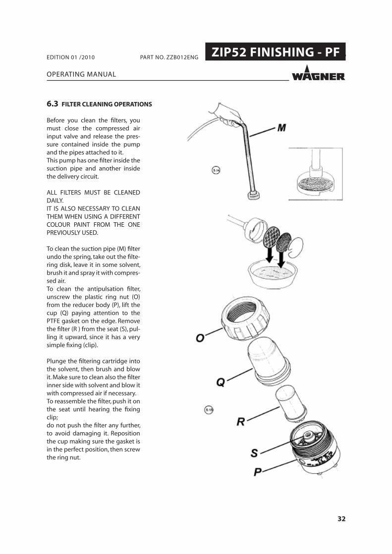
Before you clean the fi lters, you must close the compressed air input valve and release the pres-sure contained inside the pump and the pipes attached to it.This pump has one fi lter inside the suction pipe and another inside the delivery circuit.
ALL FILTERS MUST BE CLEANED DAILY.IT IS ALSO NECESSARY TO CLEAN THEM WHEN USING A DIFFERENT COLOUR PAINT FROM THE ONE PREVIOUSLY USED.
To clean the suction pipe (M) fi lter undo the spring, take out the fi lte-ring disk, leave it in some solvent, brush it and spray it with compres-sed air.To clean the antipulsation fi lter, unscrew the plastic ring nut (O) from the reducer body (P), lift the cup (Q) paying attention to the PTFE gasket on the edge. Remove the fi lter (R ) from the seat (S), pul-ling it upward, since it has a very simple fi xing (clip).
Plunge the fi ltering cartridge into the solvent, then brush and blow it. Make sure to clean also the fi lter inner side with solvent and blow it with compressed air if necessary.To reassemble the fi lter, push it on the seat until hearing the fi xing clip;do not push the fi lter any further, to avoid damaging it. Reposition the cup making sure the gasket is in the perfect position, then screw the ring nut.
6.3 FILTER CLEANING OPERATIONS

33
ZIP52 FINISHING - PF .
6.1
6.2
OPERATING MANUAL
EDITION 01 /2010 PART NO. ZZB012ENG
The following instructions are general.Refer to the specifi c diagrams of each pump model to operate correctly.ATTENTION: Before you perform any maintenance or cleaning operation:- Supply yourself with the proper equipment, - Wear the garments and specifi c protection devices with regard to thenature of the fl uids with which you will come into contact,- Close the compressed air delivery and discharge the pressure from thepump and pipes connected to it, - If necessary, depending on the intervention, disconnect the product and air side connection pipes, remove the pump from the base or support it is faste-ned to and turn it over on top of a container suitable for collecting any liquid it may contain.After the pump has been reassembled following maintenance operations, re-set and check the effi ciency of the earthing connection of the individual parts of the pump.
1) Diaphragm replacement (Preventive maintenance)
Mark the coupled parts with a felt-tip pin so as to make subsequent reassembly easier.a) Remove the suction and delivery manifolds. (6.1).b) Disassemble the fastening nuts and remove the external covers. (6.2).c) Turn the two end nuts of the external diaphragm disks in contrapositionwith the appropriate spanners and disassemble one of them.d) Remove the freed diaphragm with its relative internal disk, and extract the shaft from the motor block.(6.3).e) Lock the end of the shaft released from the diaphragm in a vice (adoptingthe proper precautions to avoid damaging it) and disassemble the external diaphragm disk from the opposite end. Now remove the second diaphragm with its internal disk.f ) Assemble the new diaphragm with its internal disk and opportunely tighten it with the relevant external disk.g) Free the shaft from the vice, put it inside the motor block after lubricating it with grease, assemble the internal diaphragm disk, diaphragm and external disk, and then properly tighten it by using two spanners in contraposition on the nuts of the external disks.h) Reassemble the external covers and then the manifolds while making sure you check the positioning of the suction and delivery valves, the relative seals and proper tightening of the screws. (6.4).
2) Diaphragm replacement (due to breakage)
In the case the diaphragms are replaced as a consequence of breaking, it is ne-cessary to clean all the internal parts of the motor and check the condition of the seals and reversing valve, which may have been damaged by contact with the pumped fl uid.a) Follow the sequence described under paragraph 1, points a), b), c), d) and e).b) Disassemble the pressure side cover and extract the reversing valve.
6.4 MACHINE MAINTENANCE

34
ZIP52 FINISHING - PF .
6.4
OPERATING MANUAL
EDITION 01 /2010 PART NO. ZZB012ENG
c) Remove the rod guide bushings placed at the two ends of the motor block, the shaft seals and feeler pin underneath and extract the feeler pins. (6.4).d) Clean all the components, the lines and spaces inside the motor block.Thoroughly blow the housing cavity of the safety valve with a jet of compressed air.e) Check the condition of the reversing valve and replace it, if necessary.f ) Reassemble all the parts described under point c) while paying attention that you properly orient the seal lip of the gaskets.g) Reassemble the valve in its housing, check that the shoe is in the end of stroke position both vertically and horizontally, and then put the pressure side cover on.As you are performing the operations described above, check the positioning of the valves seals and cover.h) Reassemble the remaining components by following the instructions under paragraph 1, points f ), g), h).3) Cleaning and/or replacement of the suction and delivery valvesa) Remove the suction and delivery manifolds.b) Extract the gaskets, seats and ball valves from the external cover and manifold housings.c) Check the condition of wear of the ball guide/stops inside the covers and manifold.

35
ZIP52 FINISHING - PF .
OPERATING MANUAL
EDITION 01 /2010 PART NO. ZZB012ENG
7 ACCESSORIES
7.1 ACCESSORIES ONLY FOR 2301832, 2301836, 2301837

36
ZIP52 FINISHING - PF .
OPERATING MANUAL
EDITION 01 /2010 PART NO. ZZB012ENG
7.2 PUMP ZIP 52 FINISHING WITH WALL SUPPORTING KIT COD. T760.00M

37
ZIP52 FINISHING - PF .
OPERATING MANUAL
EDITION 01 /2010 PART NO. ZZB012ENG
Spare parts list T760.00M
Pos Description Qty. No.
51 Right wall bracket 1 E3101.92B
52 Left wall bracket 1 E3101.92A
53 TCEI 8x20 screw 4 K120.62
54 RWasher 8 4 K509.62
55 Nut 4 K312.62
58 Washer 4 K572.62
7.2.1 OVERALL DIMENSIONS COD. T760.00M

38
ZIP52 FINISHING - PF .
OPERATING MANUAL
EDITION 01 /2010 PART NO. ZZB012ENG
7.3 PUMP ZIP 52 FINISHING WITH STAND KIT COD. T760.00S

39
ZIP52 FINISHING - PF .
OPERATING MANUAL
EDITION 01 /2010 PART NO. ZZB012ENG
Spare parts list T760.00S
Pos Description Qty. Code
21 Washer 5 K505.62
34 Nut 5 K311.62A
38 Right stand 1 E3107.92
39 Left stand 1 E3107.92A
40 Stand pin 1 H1156.62
41 Finned push rod 4 R204.07
42 Plyers foot 4 R244.07
43 TCEI 6x45 screw 4 K184.62
44 TCEI 8x40 screw 2 K1015.62
45 Gun hook 1 H009.62
57 Contact washer 4 K564.72
7.3.1 OVERALL DIMENSIONS COD. T760.00S

40
ZIP52 FINISHING - PF .
OPERATING MANUAL
EDITION 01 /2010 PART NO. ZZB012ENG
7.4 PUMP ZIP 52 FINISHING WITH HANDLE+WHEELS KIT COD. T760.00R FOR STAND PUMPS COD. T760.00S

41
ZIP52 FINISHING - PF .
OPERATING MANUAL
EDITION 01 /2010 PART NO. ZZB012ENG
Spare parts list T760.00R
Pos Description Qty. Code
34 Nut 2 K311.62A
46 Wheel 2 R118.00
47 Benzing ring 2 K607.02
48 Trolley handle 1 E3108.92
49 TCEI 6x50 screw 2 K159.62
50 Washer 4 K502.62
57 Contact washer 4 K564.72
7.4.1 OVERALL DIMENSIONS COD. T760.00R

42
ZIP52 FINISHING - PF .
OPERATING MANUAL
EDITION 01 /2010 PART NO. ZZB012ENG
7.5 POMPA ZIP 52 FINISHING WITH TROLLEY KIT COD. T760.00SR
43
ZIP52 FINISHING - PF .
OPERATING MANUAL
EDITION 01 /2010 PART NO. ZZB012ENG
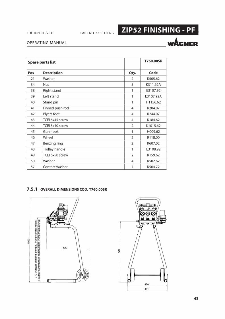
Spare parts list T760.00SR
Pos Description Qty. Code
21 Washer 2 K505.62
34 Nut 5 K311.62A
38 Right stand 1 E3107.92
39 Left stand 1 E3107.92A
40 Stand pin 1 H1156.62
41 Finned push rod 4 R204.07
42 Plyers foot 4 R244.07
43 TCEI 6x45 screw 4 K184.62
44 TCEI 8x40 screw 2 K1015.62
45 Gun hook 1 H009.62
46 Wheel 2 R118.00
47 Benzing ring 2 K607.02
48 Trolley handle 1 E3108.92
49 TCEI 6x50 screw 2 K159.62
50 Washer 4 K502.62
57 Contact washer 7 K564.72
7.5.1 OVERALL DIMENSIONS COD. T760.00SR

44
ZIP52 FINISHING - PF .
OPERATING MANUAL
EDITION 01 /2010 PART NO. ZZB012ENG
8 SPARE PARTS
8.1 HOW TO ORDER SPARE PARTS
45
ZIP52 FINISHING - PF .
OPERATING MANUAL
EDITION 01 /2010 PART NO. ZZB012ENG

46
ZIP52 FINISHING - PF .
2301832, 2301836, 2301837 2301838
OPERATING MANUAL
EDITION 01 /2010 PART NO. ZZB012ENG
8.2 OVERVIEW MODULES
ZIP52 FINISHING - PF 2301832 2301836 2301837 2301838
Pos Description No. Qty No. Qty No. Qty No. Qty
1 Pump ZIP52 (see the exploded view 8.3.3)
Aluminium 1 Inox 1 Plastic 1 Alluminium 1
2 Fine Flow Controller (see the exploded view 8.3.1, 8.3.5)
T0180.00A 1 T0180.00AI 1 T0180.00AT0180.00AI
1 - -
3 Material tank fi lter (see the exploded view 8.3.6)
- - - - - - T4005.00ALS 1
4 Suction pipe (see the exploded view 8.3.7)
T406.00 1 T406.00 1 T406.00 1 T406.00 1
5 Leg See Accessories
- See Accessories
- See Accessories
- E111.92B 2
- Pump equipped with protection panel - air pressure reducers and manometers to adjust: pump motor
feeding air, fl uid reducer controlling air, atomising air , re-cycle pipe with lever valve support.
support trestle -relevant gauges for pump feeding air and atomising air
- recycling pipe with manual valve.
47
ZIP52 FINISHING - PF .
(2301832)
OPERATING MANUAL
EDITION 01 /2010 PART NO. ZZB012ENG
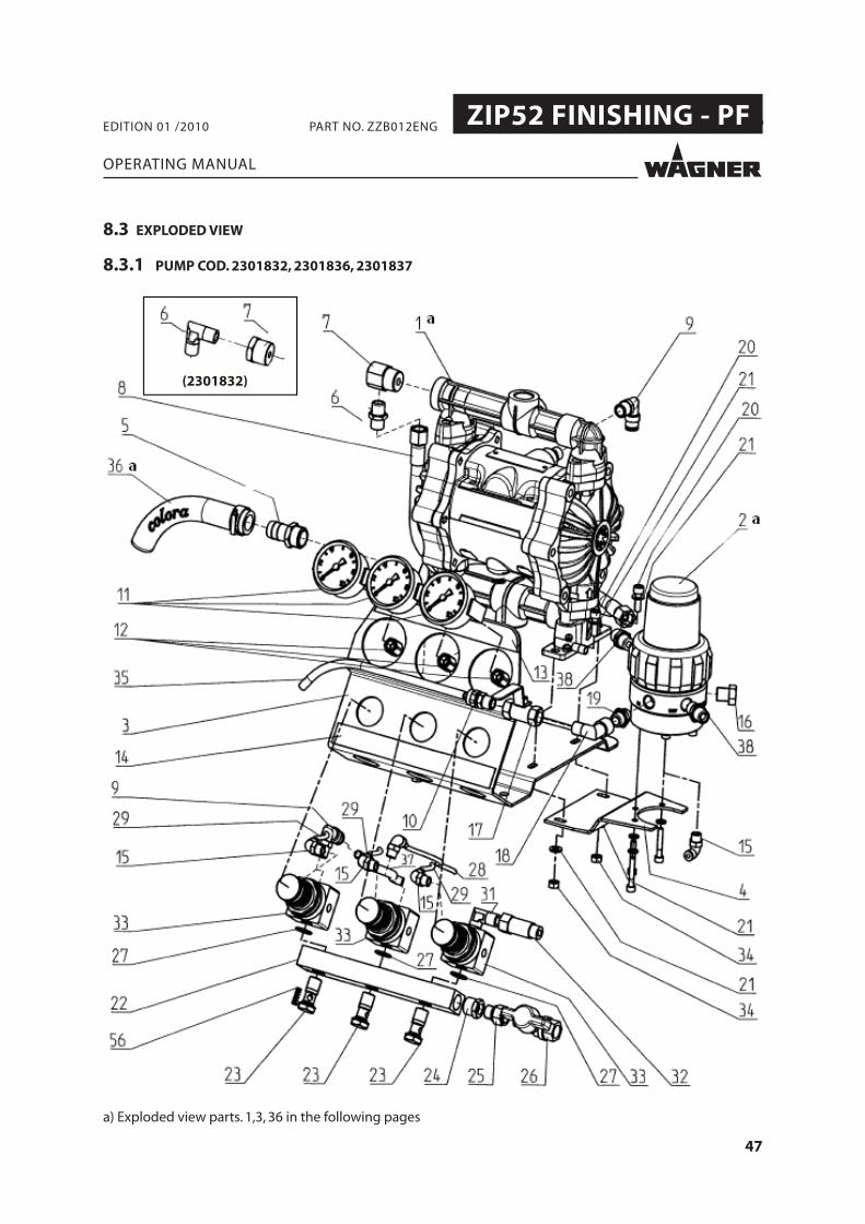
8.3 EXPLODED VIEW
8.3.1 PUMP COD. 2301832, 2301836, 2301837
a) Exploded view parts. 1,3, 36 in the following pages

48
ZIP52 FINISHING - PF .
OPERATING MANUAL
EDITION 01 /2010 PART NO. ZZB012ENG
Spare parts list 2301837 2301832 2301836
Pos Description Qty. Code Qty. Code Qty. Code
1 ZIP 52 pump 1 see explod.view
1 see explod.view
1 see explod.view
2 Fine Flow controller 1 T0180.00AI 1 T0180.00AI 1 T0180.00AI
3 Pump support 1 E3105.92 1 E3105.92 1 E3105.92
4 Reducer support 1 E3106.92 1 E3106.92 1 E3106.92
5 Flexible pipe holder 1/2”x16 stainless steel
1 B274.03 1 B274.03 1 B274.03
6 Nipple 1/4” 1 M801.03B 1 M801.03B
7 Fitting spec.1/2” 1 B0264.03 1 M247.00 1 B0264.03
8 Paint hose 1 S591.00C 1 S591.00C 1 S591.00C
9 Rapid revolving connector L 1/4”x8
2 M336.00 2 M336.00 2 M336.00
10 Fitting 1/4x8 1 M057.07
11 Pressure gauge 3 P904.00 3 P904.00 3 P904.00
12 Rapid connector D1/8”x4 F 3 M286.00 3 M286.00 3 M286.00
13 Control plate 1 Z547.00 1 Z547.00 1 Z547.00
14 “ZIP52 fi nishing” label 1 Z548.00 1 Z548.00 1 Z548.00
15 Rapid revolving connector L 1/8”x4
4 M335.00 4 M335.00 4 M335.00
16 Plug 1/4” 1 M826.03B 1 M259.00 1 M826.03B
17 Cock FF 1/4” lever 1 M513.00IA 1 M109.00 1 M513.00IA
18 Fitting L MF 1/4” 1 M881.03 1 M213.04 1 M881.03
19 Conical nipple 1/4” 1 M801.03C 1 M205.04 1 M801.03C
20 TCEI M6x20 screw 4 K107.62 4 K107.62 4 K107.62

49
ZIP52 FINISHING - PF .
OPERATING MANUAL
EDITION 01 /2010 PART NO. ZZB012ENG
Spare parts list 2301837 2301832 2301836
Pos Description Qty. Code Qty. Code Qty. Code
21 Washer 8 K505.62 8 K505.62 8 K505.62
22 Air manifold 1 T139.01 1 T139.01 1 T139.01
23 Hollow screw 1/4” 3 M404.00 3 M404.00 3 M404.00
24 Reduction MF 3/8”x1/4” 1 M250.00 1 M250.00 1 M250.00
25 Fitting D MF 1/4” 1 M239.00 1 M239.00 1 M239.00
26 Throttle cock MF 1/4” 1 M101.00 1 M101.00 1 M101.00
27 O-ring 3 L212.06 3 L212.06 3 L212.06
28 Paint reducer air pipe 1 S455.07A 1 S455.07A 1 S455.07A
29 Manometer reducer pipe 3 S455.07 3 S455.07 3 S455.07
30 Rapid revolving connector L 1/4”x4
1 M354.00 1 M354.00 1 M354.00
31 Fitting L MM 1/4” 1 M215.04 2 M215.04 1 M215.04
32 Extension MF 1/4” 1 M204.04 1 M204.04 1 M204.04
33 Air pressure reducer 1/4” 3 P123.00 3 P123.00 3 P123.00
34 Nut 4 K311.62A 4 K311.62A 4 K311.62A
35 Re-cyle pipe 2 mt S103.07N 2 mt S401.00 2 mt S103.07N
36 Suction pipe 1 T406.00 1 T406.00 1 T406.00
37 Pump feeding air pipe 1 S455.07B 1 S455.07B 1 S455.07B
38 Nipple 1/4” 2 M801.03B 2 M801.03B 2 M801.03B
56 Contact spring 1 H261.03 1 H261.03 1 H261.03

50
ZIP52 FINISHING - PF .
18 a
OPERATING MANUAL
EDITION 01 /2010 PART NO. ZZB012ENG
8.3.2 PUMP COD. 2301838
a) Exploded view parts. 18 in the following pages

51
ZIP52 FINISHING - PF .
OPERATING MANUAL
EDITION 01 /2010 PART NO. ZZB012ENG
Spare parts list 2301838
Pos Description Qty. Code
1 ZIP52 PF pump 1 U551.AHSS1see explod. view
2 Pump support 1 E3112.92
3 Leg 2 E111.92B
4 Finned push rod 4 R211.07
5 Air pressure reducer 1/4” 2 P123.00E
6 Pressure gauge 2 P936.00
7 Rapid revolving connector L 1/4”x8 3 M336.00
8 Conical nipple 1/4” 1 M205.04
9 Fitting T MFM 1/4” 1 M340.00
10 Flexible pipe holder 1/2”x16 1 M208.04
11 Cylindrical plug ½” 1 M254.14A
12 Cock MF 1/4” lever 1 M109.00
13 Re-cyle pipe 1 S401.00
14 Suction pipe ST 1 T406.00
15 Pipe 300 mm S103.07N
16 Fitting L MM 1/4” 1 M215.04
17 Reduced nipple 1 M618.62
18 Material fi lter 1 T4005.00ALS
19 Nipple 1 M631.62

52
ZIP52 FINISHING - PF .
OPERATING MANUAL
EDITION 01 /2010 PART NO. ZZB012ENG
Spare parts list 2301838
Pos Description Qty. Code
20 Plug E.I. 1/4” 1 M623.12
21 Fitting L MF 1/4” 1 M213.04
22 TCEI M6x20 screw 4 K107.62
23 Washer 8 K505.62
24 Self-tightening nut 8 K311.62
25 Vite TCEI M4x50 2 K166.62
26 Washer 4 K501.62
27 Nut 2 K302.62
28 TCEI M6x55 screw 4 K134.62
29 Contact washer 8 K564.72

53
ZIP52 FINISHING - PF .25 9 22 24 23 17
197
26
8
2,5
Nm
(Pla
stic
a/Pl
astic
/Pla
stiq
ue/K
unst
off) 2,
5 N
m (P
last
ica/
Plas
tic/P
last
ique
/Kun
stof
f)
OPERATING MANUAL
EDITION 01 /2010 PART NO. ZZB012ENG
8.3.3 PUMP ZIP 52
54
ZIP52 FINISHING - PF .
OPERATING MANUAL
EDITION 01 /2010 PART NO. ZZB012ENG
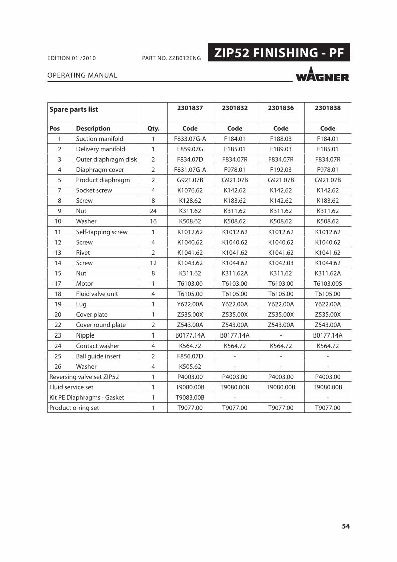
Spare parts list 2301837 2301832 2301836 2301838
Pos Description Qty. Code Code Code Code
1 Suction manifold 1 F833.07G-A F184.01 F188.03 F184.01
2 Delivery manifold 1 F859.07G F185.01 F189.03 F185.01
3 Outer diaphragm disk 2 F834.07D F834.07R F834.07R F834.07R
4 Diaphragm cover 2 F831.07G-A F978.01 F192.03 F978.01
5 Product diaphragm 2 G921.07B G921.07B G921.07B G921.07B
7 Socket screw 4 K1076.62 K142.62 K142.62 K142.62
8 Screw 8 K128.62 K183.62 K142.62 K183.62
9 Nut 24 K311.62 K311.62 K311.62 K311.62
10 Washer 16 K508.62 K508.62 K508.62 K508.62
11 Self-tapping screw 1 K1012.62 K1012.62 K1012.62 K1012.62
12 Screw 4 K1040.62 K1040.62 K1040.62 K1040.62
13 Rivet 2 K1041.62 K1041.62 K1041.62 K1041.62
14 Screw 12 K1043.62 K1044.62 K1042.03 K1044.62
15 Nut 8 K311.62 K311.62A K311.62 K311.62A
17 Motor 1 T6103.00 T6103.00 T6103.00 T6103.00S
18 Fluid valve unit 4 T6105.00 T6105.00 T6105.00 T6105.00
19 Lug 1 Y622.00A Y622.00A Y622.00A Y622.00A
20 Cover plate 1 Z535.00X Z535.00X Z535.00X Z535.00X
22 Cover round plate 2 Z543.00A Z543.00A Z543.00A Z543.00A
23 Nipple 1 B0177.14A B0177.14A - B0177.14A
24 Contact washer 4 K564.72 K564.72 K564.72 K564.72
25 Ball guide insert 2 F856.07D - - -
26 Washer 4 K505.62 - - -
Reversing valve set ZIP52 1 P4003.00 P4003.00 P4003.00 P4003.00
Fluid service set 1 T9080.00B T9080.00B T9080.00B T9080.00B
Kit PE Diaphragms - Gasket 1 T9083.00B - - -
Product o-ring set 1 T9077.00 T9077.00 T9077.00 T9077.00

55
ZIP52 FINISHING - PF .
OPERATING MANUAL
EDITION 01 /2010 PART NO. ZZB012ENG
8.3.4 AIR MOTOR PUMP ZIP52

56
ZIP52 FINISHING - PF .
OPERATING MANUAL
EDITION 01 /2010 PART NO. ZZB012ENG
Spare parts list 2301837, 2301832, 2301836
2301838
Pos Description Qty. Code Code
Motor ZIP52 Without cycle counter connection
1 T6103.00 T6103.00S
Motor ZIP52 With cycle counter connection
1 T6103.00C T6103.00G
1 Feeler pin 2 B0146.04 B0146.04
2 Inner diaphragm disk 2 B0147.71 B0147.71
3 Shaft 1 B0150.03 B0150.03S
4 Cover (pressure side) 1 F194.91 F194.91
5 Bushing guide rod 2 F829.07 F829.07
6 Cover (discharge side) 1 F830.07 F830.07
7Motor block with safety valve
T6103.00, T6103.00S 1 T6103.00A T6103.00A
T6103.00C, T6103.00G 1 T6103.00F T6103.00F
8 Reversing valve gasket 1 G925.06 G925.06
9 Pressure cover gasket 1 G7020.06 G7020.06
10 Silencer 1 H618.07 H618.07
11 Screw 4 K1038.62 K1038.62
12 Screw 6 K1039.62 K1039.62
13 Lip gasket 2 L470.06 L470.06
14 Lip gasket 2 L471.06 L471.06
15 Reversing valve 1 P4003.00 (*) P4003.00 (*)
16 Safety valve 1 (**) (**)
17 Side plate 1 Z546.00 Z546.00
18 Screw (T6103.00C o T6103.00G) 1 K174.62 K174.62
19 Washer(T6103.00C o T6103.00G) 1 K535.07 K535.07
(*) The spare part includes the reversing valve gasket code G925.06 and pressure cover gasket code G7020.06
(**) Not available separately. See pos. 7

57
ZIP52 FINISHING - PF .
OPERATING MANUAL
EDITION 01 /2010 PART NO. ZZB012ENG
8.3.5 FINE FLOW CONTROLLER T0180.00A, T0180.00AI

58
ZIP52 FINISHING - PF .
OPERATING MANUAL
EDITION 01 /2010 PART NO. ZZB012ENG
Spare parts list T0180.00A, T0180.00AI
Pos Description Qty. Code
1 Paint diaphragm disk 1 A588.03
2 Air diaphragm disk 1 A590.03
3 Ball guide body 1 B0172.03
4 Reducer body – fl uid sideT0180.00AT0180.00AI
11
B0180.01B0180.03
5 Valve stem 1 B391.03
6 Reducer body – air side 1 B563.01
7 Complete ball seat body 1 T6007.00A
8 Lockring 1 F991.07
9 Cup 1 F992.07
10 PTFE paint pressure reducer diaphragm 1 G725.05
11 Paint pressure reducer diaphragm 1 G726.06
12 Gasket 1 G640.05B
13 Conical spring 1 H285.03
14 Self-tightening nut 1 K311.62
15 Washer 6 K515.62
16 Ball 1/4” 1 K811.03
17 TCEI M5x30 screw 6 K1055.62
18 O-ring 1 L148.06
19 O-ring 1 L118.06A
20 Filter with collar 1 T500.00A
Service set FFC pos. 10-11-12-16-18-19 1 T9086.00

59
ZIP52 FINISHING - PF .
OPERATING MANUAL
EDITION 01 /2010 PART NO. ZZB012ENG
8.3.6 MATERIAL FILTER 1/2 ALUMINIUM COD. T4005.00ALS (FOR 2301838)

60
ZIP52 FINISHING - PF .
OPERATING MANUAL
EDITION 01 /2010 PART NO. ZZB012ENG
Spare parts list T4005.00ALS
Pos Description Qty. Code
1 Filter body 1 B0259.01
2 Filter cover 1 B0127.01
3 Tank fi lter 1 T454.00
4 Stainless steel spring 1 H282.03
5 Filter tie rod 1 H1152.03
6 Filter lockring 1 B0128.03
7 Tank seal Joint reservoir 1 G605.07

61
ZIP52 FINISHING - PF .
1010
OPERATING MANUAL
EDITION 01 /2010 PART NO. ZZB012ENG
8.3.7 SUCTION PIPE + RE-CYCLE PIPE COD. T406.00, T406.00A

62
ZIP52 FINISHING - PF .
OPERATING MANUAL
EDITION 01 /2010 PART NO. ZZB012ENG
Spare parts list T406.00, T406.00A
Pos Description Qty. Code
1 Suction pipe spring 1 H206.03
2 Filter disk 1 H401.07
3 Hose clamp 2 R601.00
4 Solvent resistant Suction tubeT406.00 (3811721) (L=900 mm)T406.00A (3811722) (L=1200 mm)
11
S402.06AS402.06C
5 Metal suction pipe 1 S637.03
6 Suction pipe fi lter 1 T453.03
7 ST Suction pipe cup 1 F141.07
8 Suction pipe ST - stiff part 1 T404.00
9 Suction pipe ST - complete metallic part 1 T420.00
10 Contact clip 2 E0107.03
56 Suction pipe 1 T406.00
57 Re-cycle pipe 1 S401.00
58 Plastic clamp 4 R602.07A

63
ZIP52 FINISHING - PF .
OPERATING MANUAL
EDITION 01 /2010 PART NO. ZZB012ENG

64
ZIP52 FINISHING - PF .
OPERATING MANUAL
EDITION 01 /2010 PART NO. ZZB012ENG

65
ZIP52 FINISHING - PF .
A J. Wagner Ges.m.b.H. Ottogasse 2/20 2333 Leopoldsdorf Österreich Tel. +43/ 2235 / 44 158 Telefax +43/ 2235 / 44 163 offi [email protected]
B Wagner Spraytech Benelux b.v. Veilinglaan 56 1861 Meise-Wolvertem Belgium Tel. +32/2/269 46 75 Telefax +32/2/269 78 45 [email protected]
CH Wagner International AG Industriestrasse 22 9450 Altstätten Schweiz Tel. +41/71 / 7 57 22 11 Telefax +41/71 / 7 57 22 22 [email protected]
D J. Wagner GmbH Otto-Lilienthal-Straße 18 D-88677 Markdorf Postfach 11 20 D-88669 Markdorf Deutschland Tel.: +49 / 75 44 / 505 - 664 Fax: +49 / 75 44 / 505 -155 [email protected] www.wagner-group.com
DK Wagner Spraytech Scandinavia A/S Helgeshøj Allé 28 2630 Taastrup Denmark Tel. +45/43/ 27 18 18 Telefax +45/43/ 43 05 28 [email protected]
E Wagner Spraytech Iberica S.A. P.O. Box 132, Crta. N-340 08750 Molins de Rey Barcelona / Espania Tel. +34/93/6800028 Telefax +34/93/66800555 [email protected]
F J. Wagner France S.A.R.L Parc de Gutenberg - Bâtiment F 8 voie la Cardon, 91127 Palaiseau Cedex France Tel. +33/1/825 011 111 Telefax +33/1/698 172 57 [email protected]
CZ Wagner, spol. s r.o. Nedasovská str. 345 155 21 Praha 5 -Zlicín Czechia Tel. +42/ 2 / 579 50 412 Telefax +42/ 2 / 579 51 052 [email protected]
GB Wagner Spraytech (UK) Limited The Coach House 2 Main Road Middleton Cheney OX17 2ND Great Britain UK-Helpline 0844 335 0517 5 p per minute (landline)
I Wagner Colora Via Fermi, 3 20040 Burago di Molgora (MI) Italia Tel. +39/ 039 / 625 021 Telefax +39/ 039 / 685 18 00 [email protected]
NL Wagner Spraytech Benelux b.v. Zonneban 10, 3542 EC Utrecht Netherlands Tel. +31/ 30/241 41 55 Telefax +31/ 30/241 17 87 [email protected]
S Wagner Spraytech Scandinavia A/S Helgeshøj Allé 28 2630 Taastrup Denmark Tel. +45/43/ 21 18 18 Telefax +45/43/ 43 05 28 [email protected]
OPERATING MANUAL
EDITION 01 /2010 PART NO. ZZB012ENG
9 EUROPEAN SERVICE NETWORK

66
ZIP52 FINISHING - PF .
OPERATING MANUAL
EDITION 01 /2010 PART NO. ZZB012ENG

67
ZIP52 FINISHING - PF .
OPERATING MANUAL
EDITION 01 /2010 PART NO. ZZB012ENG

ZZB012ENG