umatilla basin water study - usbr.gov ... appraisal-level water supply alternatives ... umatilla...
TRANSCRIPT
FINAL
UMATILLA BASIN WATER SUPPLY STUDY for the
Confederated Tribes of the Umatilla Indian Reservation
Prepared by: U.S. Department of the Interior Bureau of Reclamation Pacific Northwest Region Boise, Idaho January 2012
U.S. DEPARTMENT OF THE INTERIOR
Protecting America's Great Outdoors and Powering Our Future
The U.S. Department of the Interior protects America's natural resources and heritage, honors our cultures and tribal communities, and supplies the energy to power our future.
MISSION OF THE BUREAU OF RECLAMATION
The mission of the Bureau of Reclamation is to manage, develop, and protect water and related resources in an environmentally and economically sound manner in the interest of the American public.

General location map.

CONTENTS
Introduction..............................................................................................................1
Study Background.....................................................................................................1
Purpose of the Study.................................................................................................2
History ...................................................................................................................3
Appraisal-Level Water Supply Alternatives ..................................................................4
Hydrology Baseline....................................................................................................5
WID Full Exchange....................................................................................................5
WID Partial Exchange................................................................................................7
HID Exchanges .........................................................................................................9 Feed Canal Exchange ......................................................................................9 Maxwell Canal Exchange ...............................................................................10
McKay Reservoir Enlargement..................................................................................11
Gravity Diversion .................................................................................................12
Pumping Facilities................................................................................................13
Appraisal-Level Water Distribution Alternative...........................................................14
CTUIR DCM&I System.............................................................................................15
Potential Return Flow Impacts Resulting from Alternatives ........................................16
Alternatives Briefly Considered But Not Included In This Study ..................................17
Cost Estimates ........................................................................................................19
Appendices
Appendix A. WID Full Exchange Figures and Layouts Appendix B. WID Partial Exchange Figures and Layouts Appendix C. HID Exchange Layouts Appendix D. McKay Reservoir Enlargement Figures and Layouts Appendix E. CTUIR On-reservation DCM&I System Figures and Layouts
List of Tables
Table 1. Alternatives Considered But Not Included..................................................17
Table 2. Umatilla Basin Water Supply Study Cost Summary .....................................20
Final Umatilla Basin Water Supply Study i
1
2
3
4
5
CONTENTS (CONTINUED)
List of Figures
Figure . Schematic of WID Full Exchange facilities.................................................6
Figure . Schematic of WID Partial Exchange facilities.............................................8
Figure . Schematic of McKay Reservoir Enlargement gravity diversion alternative..13
Figure . Pumping plant and discharge pipeline location plan. ...............................14
Figure . Schematic of proposed CTUIR DCM&I discharge system. ........................15
Final Umatilla Basin Water Supply Study ii
INTRODUCTION
The 1988 Umatilla Basin Project Act (P.L. 100-557) authorized changes in the Bureau of Reclamation’s (Reclamation) Umatilla Project (Project) operation and the construction of facilities to divert water from the Columbia River for delivery to three of the four Project irrigation districts (Hermiston, West Extension, and Stanfield irrigation districts). In exchange, those districts agreed to reduce or eliminate their diversions from the Umatilla River, thereby restoring instream flows for anadromous fish during most of the year. The Project was constructed in two phases, and resulted in a significant recovery of many Umatilla River anadromous fish stocks (including steelhead trout, which is listed as threatened under the Endangered Species Act).
The Umatilla basin is a portion of the aboriginal territory of the Confederated Tribes of the Umatilla Indian Reservation (CTUIR or Tribes). In 1855, the CTUIR executed a treaty with the United States, which established the Umatilla Indian Reservation as the permanent homeland for the Tribes, and reserved exclusive fishing rights within their Reservation as well as rights to fish at usual and accustomed fishing stations located outside the Reservation. Pursuant to the U.S. Supreme Court decision in the case of Winters v. United States 207 U.S. 564 (1908), the CTUIR claims federally reserved water rights to satisfy the principal purposes for which the Umatilla Indian Reservation was established and instream flows to support its treaty-reserved fishery.
STUDY BACKGROUND
The Umatilla Basin Project Phase III Feasibility Study commenced in October 1998 to examine the potential for a Columbia River water exchange with the Westland Irrigation District (WID) in order to enhance instream flows in the Umatilla River. The initial focus was on a full exchange for WID to free up both natural flow and storage in McKay Reservoir. The study progressed slowly as consensus built among the stakeholders.
In February 2006, the CTUIR and WID entered into a Memorandum of Agreement requesting that the Department of the Interior (Interior) complete an engineering study for a “Phase III” water exchange project and form a federal Indian water rights assessment team. The primary objective of the engineering study was to identify measures to make WID water rights and storage in the Umatilla River basin available to help satisfy the treaty and reserved water rights of the CTUIR.
Interior consulted with Reclamation to determine if the broader scope of the alternatives for consideration under the water rights assessment process could be included under the umbrella of the ongoing Phase III Feasibility Study. Since the assessment process planned
Final Umatilla Basin Water Supply Study 1
to consider on-reservation infrastructure, Reclamation administratively determined that the feasibility study authority was not broad enough. Reclamation advised Interior that while the feasibility study authority was insufficient, there was existing authority to allow the broader study to proceed at an appraisal level.
In March 2007, Interior offered to conduct an appraisal-level water supply study of the Umatilla River basin focusing on measures to address CTUIR water needs. The Umatilla Basin Water Supply Study (UBWSS) was subsequently initiated and superseded the Phase III Feasibility Study. Representatives of Reclamation and the Umatilla River Federal Indian Water Rights Assessment Team (Assessment Team) concurrently met with representatives of the CTUIR, WID, and the Oregon Water Resources Department (OWRD) to start the assessment process.
PURPOSE OF THE STUDY
Work performed during the UBWSS was intended as technical input to the Assessment Team process. As such, the study focused on identifying appraisal-level alternatives that could augment surface water supplies in the Umatilla basin to help satisfy treaty and reserved water-rights claims of the CTUIR while keeping existing water users whole.
The CTUIR has identified 374,000 acre-feet in surface water claims for both non-consumptive use (off-reservation instream flow enhancement) and consumptive use (irrigation and domestic, commercial, municipal, and industrial (DCM&I1)). A document prepared by the CTUIR in August 2007 indicated their estimated minimum surface water claims to be:
Surface Water Use Amount
Irrigation
DCM&I
Umatilla River instream flows
Total
50,000 acre-feet per year
13,500 acre-feet per year
310,500 acre-feet per year
374,000 acre-feet per year
About 96 percent of the instream flow needs are already present in the river because of wintertime natural flows and exchanges occurring because of construction of Phases I and II of the Umatilla Basin Project. This would indicate a need for an additional 12,500 acre-feet for instream flows. Alternatives identified in this report focus on ways to augment surface water supplies to help meet the instream flow claims and the 63,500 acre-feet of consumptive use claims.
1 DCM&I water is typically used to meet potable and non-potable water needs associated with household (domestic/municipal), commercial (i.e., restaurant and other small businesses), and industrial users.
Final Umatilla Basin Water Supply Study 2
The CTUIR is in the process of quantifying its groundwater claims so potential resolution of those claims is not addressed in this report.
HISTORY
The original Project furnishes a supply of irrigation water to over 17,000 acres and a supplemental supply to approximately 13,000 acres. The original Project’s authorized purpose was irrigation. These irrigated lands comprise three separate divisions:
• East Division – Hermiston Irrigation District (HID)
• West Division – West Extension Irrigation District (WEID)
• South Division – Stanfield Irrigation District (SID) and WID
Under the 1988 Umatilla Basin Project Act (P.L. 100-557), facilities were constructed to improve passage and restore instream flows for anadromous fish while allowing established irrigation to continue. These facilities included fish screens at Maxwell Diversion Dam, fish screens and a ladder at Feed Canal Diversion Dam, and construction of water exchange facilities (Phases I and II) to deliver irrigation replacement water from the Columbia River.
The Phase I water exchange facilities serve the WEID. Construction began in January 1990 and was completed in 1993.
The Phase II water exchange facilities serve HID and SID. Construction of Phase II facilities began in June 1993 with the Columbia River Pumping Plant (CRPP) and Discharge Line; all facilities were completed in 1999. Columbia River exchange water is delivered to Cold Springs Reservoir for the HID and delivered directly into the SID’s system. Phase II included eight major features:
• CRPP and Discharge Line
• Columbia-Cold Springs Canal
• Cold Springs Reservoir Pumping Plant and Discharge Line
• North Branch Furnish Canal Enlargement
• Stanfield Branch Furnish Canal Enlargement
• Stanfield Relift Pumping Plant and Discharge Line
• Upper Furnish and Echo Area Facilities
• Supervisory Control & Data Acquisition (SCADA) System
Final Umatilla Basin Water Supply Study 3
APPRAISAL-LEVEL WATER SUPPLY ALTERNATIVES
The UBWSS considered a number of alternatives to achieve the purpose of the study. The following alternatives are those selected for a more detailed evaluation following screening of a broader range of alternatives.2
1. WID Full Exchange (also known as Phase III exchange)
2. WID Partial Exchange
3. HID Exchange (two potential exchanges)
- Feed Canal - Maxwell Canal
4. McKay Reservoir Enlargement (two options to help fill enlarged reservoir)
- Gravity Diversion from Umatilla River - Pumping from Umatilla River
A basic assumption of the exchange alternatives presented in this report is that agreements comparable to those prepared for the Phase I and II water exchanges would be required as part of any future implementation of one or more of the alternatives. In addition, water rights would have to be acquired as part of implementing at least some of the proposed alternatives. The details necessary to properly define operational criteria and associated effects, the needed water rights, and terms of any exchange agreements have not been identified at this stage of the assessment process. These details will be developed in the event any of the alternatives are evaluated at a feasibility level of detail in the future.
The information presented herein is appropriate for an appraisal-level investigation to help identify major constraints to implementing an alternative or issues that make an alternative infeasible or potentially cost prohibitive.
If the study moves forward into a feasibility-level investigation, extensive environmental surveys and analyses will be completed to verify the presence of, and accurately assess potential effects to return flows, cultural and historic resources, species, habitat, and other resources.
The following narratives provide a brief overview of each water supply alternative. A cost summary follows the narrative sections describing estimated appraisal-level construction costs plus associated operations, maintenance, and power costs. Since this report was prepared to support an ongoing Native American water rights assessment process, no repayment evaluation was prepared.
2 See Section “Alternatives Briefly Considered but Not Included in this Study” later in this document.
Final Umatilla Basin Water Supply Study 4
HYDROLOGY BASELINE
Water years 2000 to 2010 were used as the period of record for assessing the water potentially made available for CTUIR use by the alternatives described in this report. This period reflects the influence of completion of the Phase I and II water exchange facilities. While the narratives presented for each of the alternatives provide peak flow amounts and average volumes, it is important to note that the actual water available in any given year would typically be more or less than the computed average.
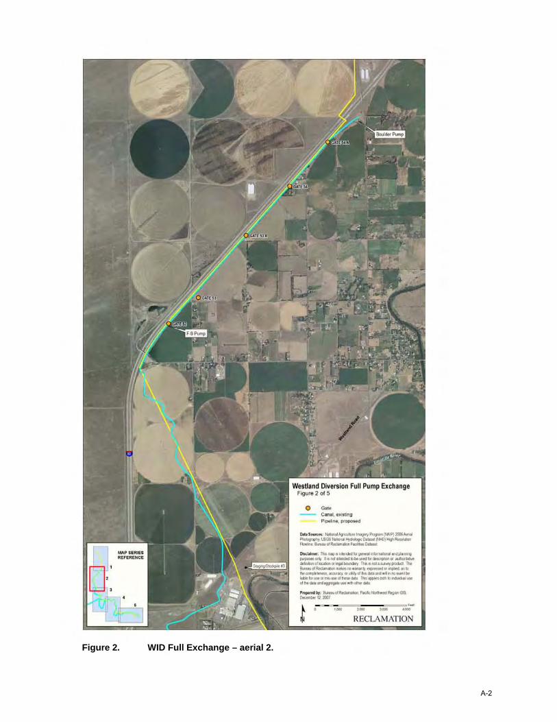
WID FULL EXCHANGE
The WID Full Exchange is a stand-alone alternative and would provide all irrigators currently supplied from the Umatilla River at Westland Diversion Dam with water from the Columbia River. This includes WID, independent pumpers (Amstad Farms, Spike Ranch, and Dick Snow – total of 4 pumps), the Allen, Pioneer, and Courtney Ditch companies, and a number of individuals and entities. This exchange could make all natural and storage (McKay Reservoir) flows currently diverted at the dam (with the exception of winter water diversions to the County Line Water Improvement District), available to the CTUIR.3
Diversions at Westland Diversion Dam currently average about 71,600 acre-feet per year with a peak daily diversion rate of about 271 cubic feet per second (cfs) based on flow records covering the period 2000 through 2010.
In addition to WID, these diversions include about 70 percent of the water diverted to the County Line Water Improvement District. Typically, the annual average diversions to the County Line Water Improvement District average 6,600 acre-feet for the period of record analyzed. Of the total, roughly 4,600 acre-feet is diverted between March and October with 2,000 acre-feet diverted during the months of November through February. The November through February diversions are not included in this exchange.
On average, WID and the independent pump irrigators divert a total of 65,000 acre-feet of water, which includes both storage and natural flow. Of that, an average of about 25,500 acre-feet of the diversions come from McKay Reservoir and include WID’s contracted storage plus storage for miscellaneous McKay contractors that divert at Westland Diversion Dam; the rest is natural flow.
3 The current alternative would have to be enlarged before it could accommodate the additional flow associated with the recent proposal to move the Dillon diversion point to Westland Diversion Dam. This option could be addressed in the event the Full Exchange Alternative is re-examined in future at a feasibility level of detail.
Final Umatilla Basin Water Supply Study 5
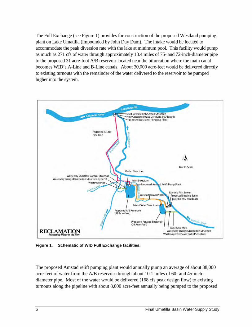
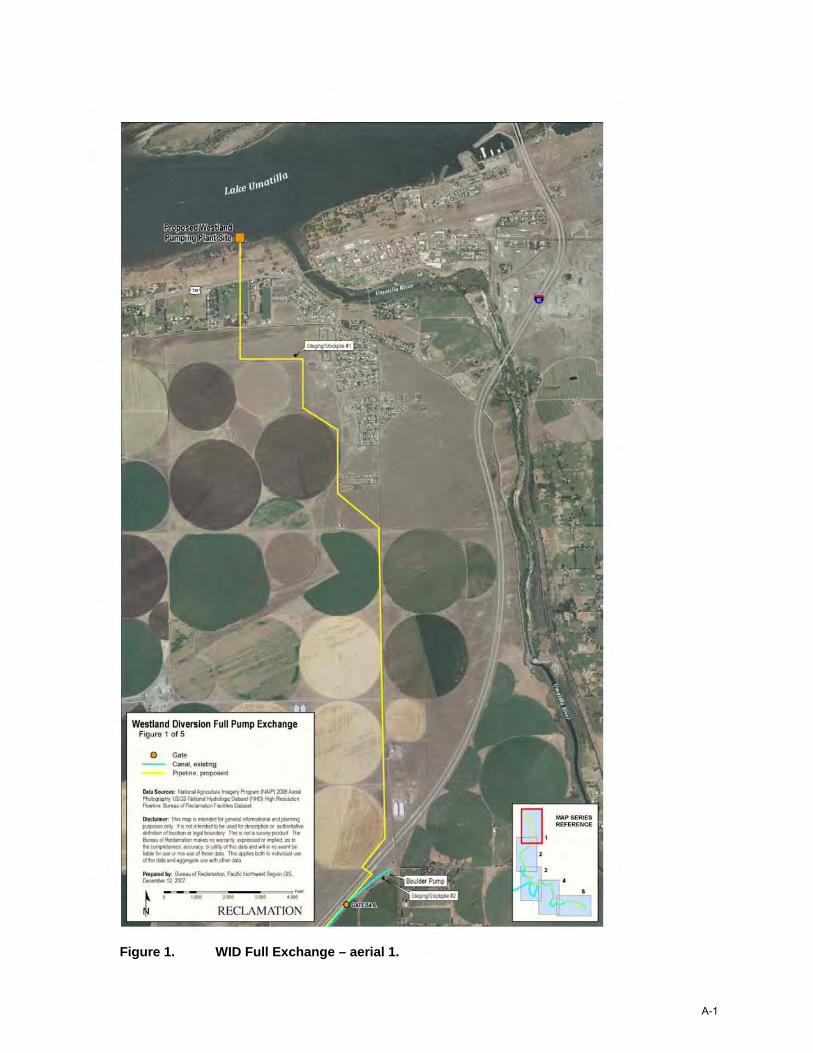
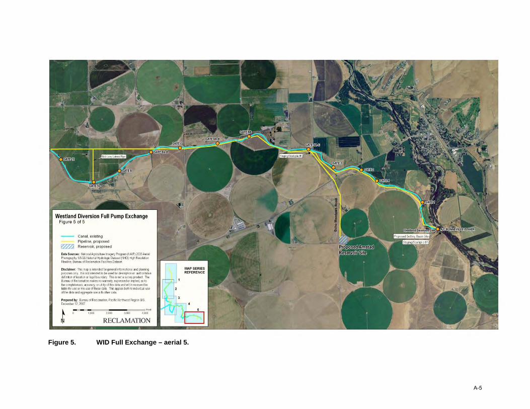
The Full Exchange (see Figure 1) provides for construction of the proposed Westland pumping plant on Lake Umatilla (impounded by John Day Dam). The intake would be located to accommodate the peak diversion rate with the lake at minimum pool. This facility would pump as much as 271 cfs of water through approximately 13.4 miles of 75- and 72-inch-diameter pipe to the proposed 31 acre-foot A/B reservoir located near the bifurcation where the main canal becomes WID’s A-Line and B-Line canals. About 30,000 acre-feet would be delivered directly to existing turnouts with the remainder of the water delivered to the reservoir to be pumped higher into the system.
Figure 1. Schematic of WID Full Exchange facilities.
The proposed Amstad relift pumping plant would annually pump an average of about 38,000 acre-feet of water from the A/B reservoir through about 10.1 miles of 60- and 45-inchdiameter pipe. Most of the water would be delivered (168 cfs peak design flow) to existing turnouts along the pipeline with about 8,000 acre-feet annually being pumped to the proposed
Final Umatilla Basin Water Supply Study 6
24 acre-foot Amstad reservoir located near Westland Diversion Dam for gravity delivery to the head end of WID’s system.
WID has 32,054 acre-feet of storage space in McKay Reservoir. The 2004 boundary adjustment contract between WID and Reclamation contains mitigation requirements, which dedicate 1,500-acre-feet of this space to instream flow augmentation and 500 acre-feet to benefit downstream users. This leaves a net of 30,054 acre-feet of space available for WID. Depending on water year conditions and carry over, these allocations may be less if the reservoir does not fill. On average, 28,500 acre-feet (of the 30,054 acre-feet) of reservoir storage space have been available to WID and have filled over the period of record analyzed.4
The proposed facilities are designed to accommodate continued diversion of Umatilla River water into the existing WID system as needed. Appendix A includes additional figures and layouts associated with the Full Exchange alternative.
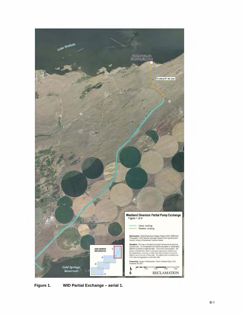
WID PARTIAL EXCHANGE
The WID Partial Exchange is a stand-alone alternative and would replace a portion of the WID diversions with Columbia River water supplied via the CRPP (Figure 2). WID and others divert water from the Umatilla River at the Westland Diversion Dam located at approximately river mile 26.75. When the live flow in the Umatilla River is insufficient for meeting both the minimum flow targets and irrigation needs, WID requests release of McKay Reservoir storage water. The Partial Exchange proposes to pump water from the Columbia River to replace an average of about 18,300 acre-feet of the water currently released from McKay Reservoir for WID.
The capacity of the CRPP would be increased to 300 cfs (including a 5 percent wear allowance) by replacing two of the existing 20 cfs pumping units with 50 cfs units (capacity of the existing plant based on current pumping curves is 250 cfs including a 5 percent wear allowance). The intake and outlet pipes for the plant would be modified as needed to accommodate the increase in size. This increase in pumping capacity would be combined with off-peak capacity in the existing plant to provide up to 90 cfs for diversion to WID.
CRPP would pump water for WID from the Columbia River into the Columbia-Cold Springs Canal. A 1-foot tall parapet wall would be constructed down both sides of the concrete-lined canal to assure minimally 2 feet of freeboard when operating at a revised design capacity of 286 cfs.
4 During the 2004 to 2010 period of record, an annual average of about 1,770 acre-feet of the mitigation water has been available for use.
Final Umatilla Basin Water Supply Study 7
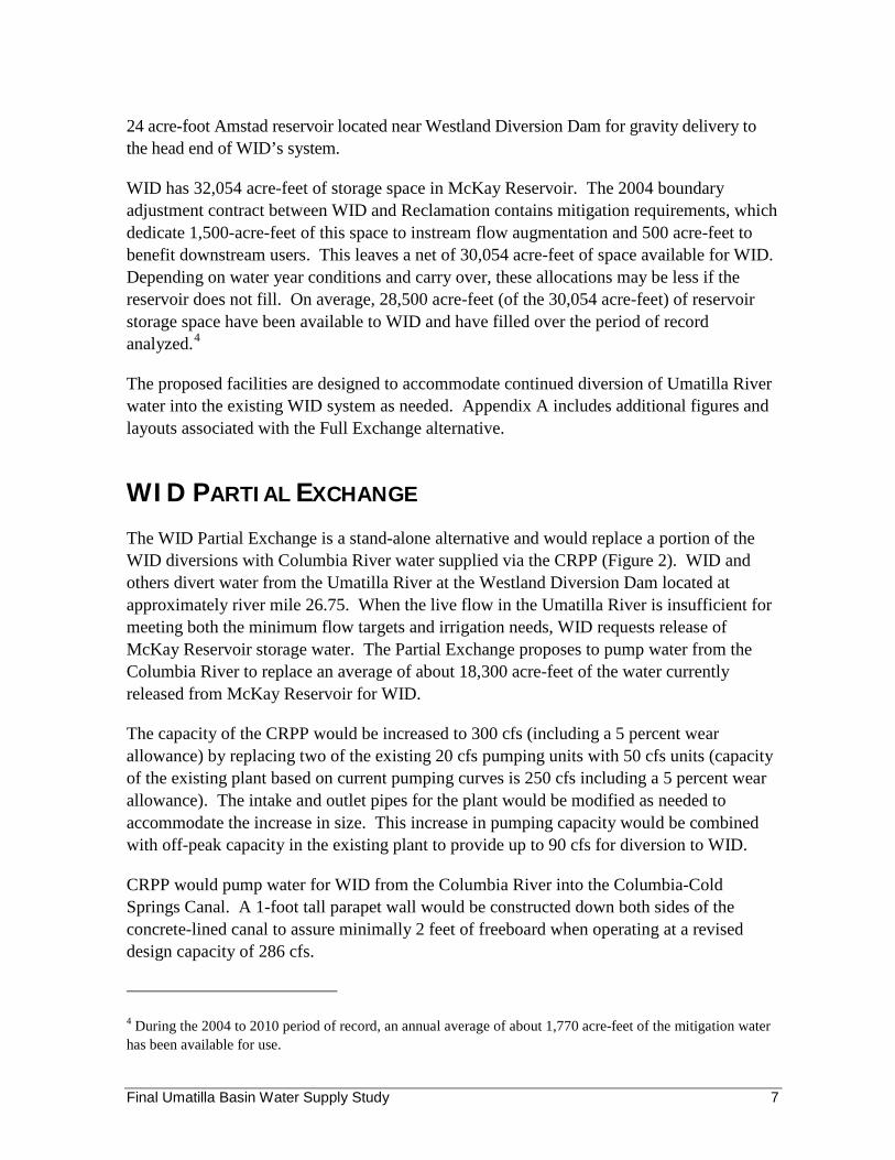
A 90 cfs relift pumping plant would be constructed at the downstream end of the canal (adjacent to the existing Cold Springs Pumping Plant) to pump water into a 45-inchdiameter discharge line approximately 62,570 linear feet long. The pipeline would terminate at the proposed (15 acre-foot) B-Line reservoir located adjacent to the bifurcation from WID’s Main Line Canal into the A-Line and B-Line canals. Water would be released from the reservoir into the WID system. A 45-inch wasteway pipeline about 2,940 linear feet long would route any overflows into nearby Butter Creek.
Figure 2. Schematic of WID Partial Exchange facilities.
If the WID Partial Exchange was combined with the Maxwell Canal exchange (discussion on page 10), t he typical partial exchange volume provided to WID would be reduced to an average of about 17,500 acre-feet due to competition with that exchange5 for CRPP pumping capacity during the peak irrigation demand pe riods.
5 This analysis model arbitrarily gives priority between the two exchanges to the Maxwell exchange, based on actual Maxwell Canal diversions during the 2000 to 2010 analysis period (as compared to the 75 cfs exchange capacity requested by HID).
Final Umatilla Basin Water Supply Study 8
Preliminary modeling suggests the WID Partial Exchange and the Feed Canal Exchange could be combined with no detrimental impact to either.
A basic premise of this alternative is that priority for use of the Phase II facilities would go to the existing HID and SID exchanges.6
Appendix B includes additional figures and layouts associated with the Partial Exchange alternative.
HID EXCHANGES
HID currently receives a portion of its water from the Columbia River in exchange for reducing its Umatilla River diversions into the Feed Canal. Two potential water exchanges were identified that could free up Umatilla River water currently diverted by HID: Feed Canal Exchange and Maxwell Canal Exchange.
Feed Canal Exchange
The Feed Canal Exchange would increase the Phase II exchange pumping to eliminate Feed Canal diversions occurring during the winter months and provide an average of up to about 38,000 additional acre-feet of Umatilla River natural flow water for CTUIR use (maximum of 34,400 acre-feet would be pumped into an enlarged McKay Reservoir; the remainder would be left instream).7
The Feed Canal Exchange would be accomplished by increasing the seasonal duration of CRPP pumping to increase the water supply available from Cold Springs Reservoir. Initial modeling results indicate that the water surface elevation in Cold Springs Reservoir could fluctuate less than it currently does. This is because Cold Springs Reservoir is filled toward the end of irrigation season before the CRPP is winterized. Additionally, the reservoir is supplied continuously with water during the irrigation season from the CRPP.
As mentioned, this alternative would compete with the WID Partial Exchange for pumping capacity in the CRPP, particularly during peak irrigation demand periods. In addition, the HID Full Exchange must be combined with a storage component (see page 11, McKay
6 Hydrologic modeling for these alternatives gives existing HID and SID exchanges priority for CRPP pumping capacity.
7 The assumption that the full diversion amount would need to be pumped is based on HID’s request and reflects their concern over the annual cost of maintaining Feed Canal and related facilities to divert an estimated 3,600 acre-feet per year if this alternative is implemented.
Final Umatilla Basin Water Supply Study 9
Reservoir Enlargement) to be effective since the Umatilla River water made available by this alternative would not correlate with the timing for identified CTUIR needs.
A monitoring program to be defined would need to be implemented to identify any return flow impacts resulting from ceasing Feed Canal diversions. Impacts on downstream users (primarily WEID) would need to be mitigated.
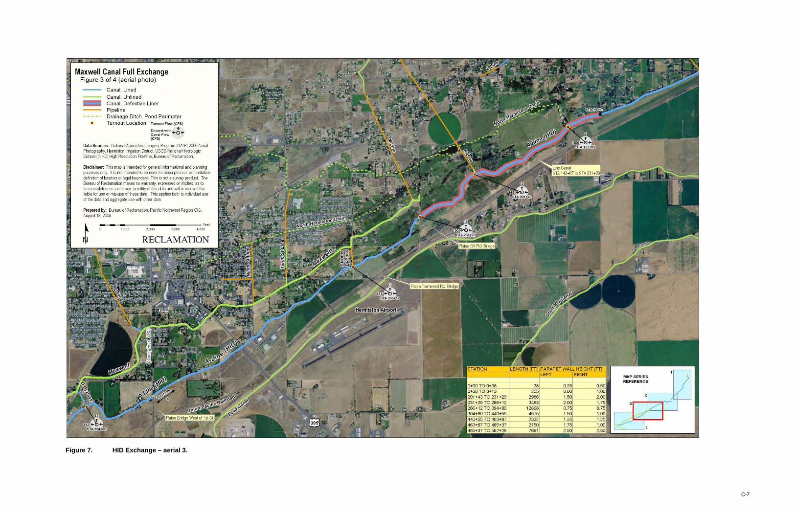
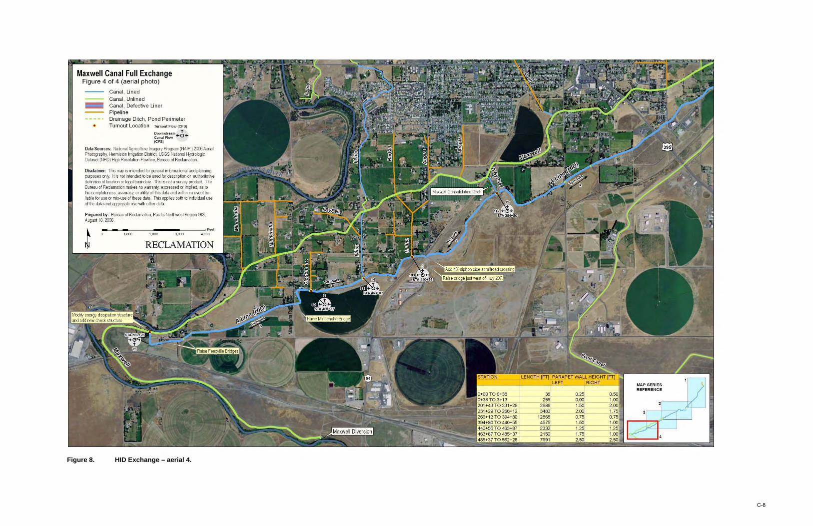
Maxwell Canal Exchange
The Maxwell Canal is served by a combination of diversions from the Umatilla River at Maxwell Diversion Dam and deliveries from Cold Springs Reservoir via four bypasses between the A-Line and Maxwell canals and a wasteway at the downstream end of the HID A-Line Canal. On average, about 4,700 acre-feet of water is annually diverted from the Umatilla River for irrigation and about 9,300 acre-feet of irrigation8 water is annually delivered via the A-Line Canal (total of about 14,000 acre-feet). HID water rights provide for diversion of up to 75 cfs and an annual diversion of up to about 18,500 acre-feet into the Maxwell Canal.
The Maxwell Canal Exchange would replace water diverted from the Umatilla River with Columbia River water delivered from Cold Springs Reservoir via the A-Line Canal. 9 Under this alternative, water currently diverted into the Maxwell Canal would be left instream for flow enhancement.
Primary measures necessary to accomplish this alternative are:
• Increasing the amount of time the CRPP and associated facilities are operated at peak capacity.
• Enlarging the HID A-Line Canal to deliver up to an additional 75 cfs from Cold Springs Reservoir to the downstream end of the canal (where it spills into the Maxwell Canal near the Umatilla River).10 This enlargement would include addition of fencing in places for public safety and measures to address existing problems with groundwater seepage.
8 Based on data provided by HID
9 The design for the A-Line Canal enlargement was sized to accommodate up to 75 cfs. This sizing is based on water rights rather than the peak flow currently diverted at Maxwell Diversion Dam. Sizing of the enlargement would be re-examined as part of any future feasibility-level evaluation of this alternative. Structural improvements would be needed to accommodate diversion of 75 cfs from the Umatilla River down the Maxwell Canal.
10 Preliminary analysis suggests that it is more cost effective to enlarge and line the existing canal rather than replace it with pipe. This analysis would be redone if this alternative were re-evaluated at a feasibility level at some point in the future.
Final Umatilla Basin Water Supply Study 10
As noted previously, this alternative would compete with the WID Partial Exchange for pumping capacity in the CRPP during peak irrigation demand periods.
Appendix C includes the figures and layouts associated with the HID Exchange alternatives.
MCKAY RESERVOIR ENLARGEMENT
The objective of the McKay Reservoir enlargement is to capture water in the Umatilla River for storage and release at different times of the year. The current active storage space in McKay Reservoir is 65,534 acre-feet and there is an additional 6,000 acre-feet of exclusive flood control space on top of the active space.
This alternative could provide up to 34,400 acre-feet of new storage space in the existing McKay Reservoir by raising the dam and constructing dikes in low areas around the perimeter of the reservoir. In most years, an external supply would be necessary to fill this new space. Two options were identified to divert Umatilla River water into the new storage space.
• Gravity diversion from the Umatilla River near Cayuse (about 13 river miles upstream of Pendleton) into a gravity pipeline discharging into the reservoir; and
• Pumping facilities from the Umatilla River downstream of Pendleton into the reservoir.
Canals were considered as an alternative to pipelines for the gravity diversion and upstream pumping options; however, preliminary evaluation of geologic conditions along the projected route indicated that a pipeline could be a better choice. The appraisal-level estimate was based on diverting 175 cfs needed to fill the potential 34,400 acre-foot McKay Reservoir enlargement during the time when HID normally diverts into Feed Canal.
Stored water for instream flow augmentation could be released through the dam’s outlet works into McKay Creek or pumped back to the Umatilla River near Cayuse to aid in temperature control (would require additional pumping facilities at McKay Reservoir not included in the current pipeline cost estimate).
Appraisal-level construction costs suggest that pumping from the Umatilla River downstream of Pendleton is the more cost effective of the two options to supply water to the enlarged McKay Reservoir.
Final Umatilla Basin Water Supply Study 11
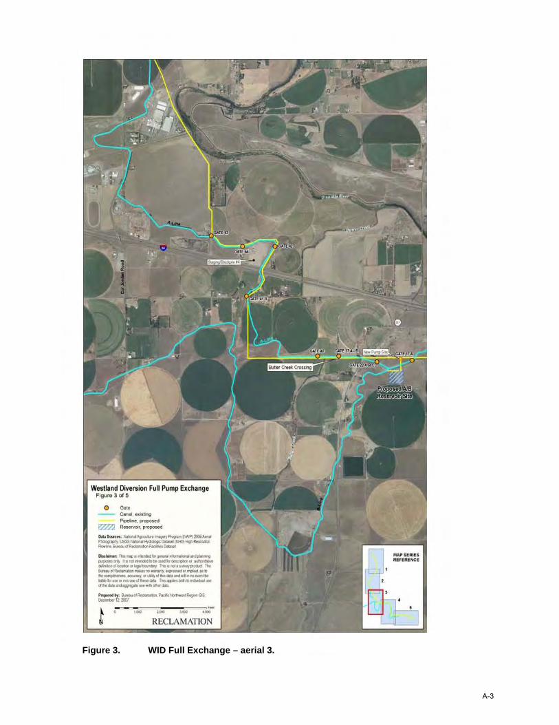
Gravity Diversion
In order to supply the active conservation storage increase for McKay Reservoir, a gravity pipeline was considered to divert water from the Umatilla River near Cayuse (see Figure 3). The storage increase will provide additional water for fish habitat enhancement for accommodating increased demands during summer low flows. A gravity diversion pipeline with a design flow of 175 cfs was analyzed in conjunction with enlarging the capacity of McKay Reservoir (see Appendix D for additional details). The pipeline would divert water from the Umatilla River during periods of high flow for storage in McKay Reservoir and then could be used to pump the water back to the Umatilla River to supplement summer low flows.
The major cost drivers for this gravity pipeline are the significantly larger diameter pipe required, the additional length necessary (when compared to the pumping alternative), and the amount of earthwork and rock excavation (plus tunneling) necessary to accommodate gravity flow. Additional detailed geologic exploration in the future may allow the estimate of the amount of rock excavation to be decreased, thereby, reducing the overall cost. Consideration could also be given to adding one or more intermediate lift stations to minimize bury depths of pipe and reduce cost.
Diversion from the Umatilla River under either alternative would be initiated only after target flows (determined by the Umatilla Management Monitoring Evaluation Oversight Committee) were satisfied.
Final Umatilla Basin Water Supply Study 12
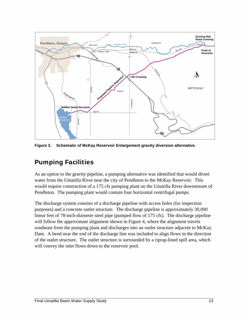
Figure 3. Schematic of McKay Reservoir Enlargement gravity diversion alternative.
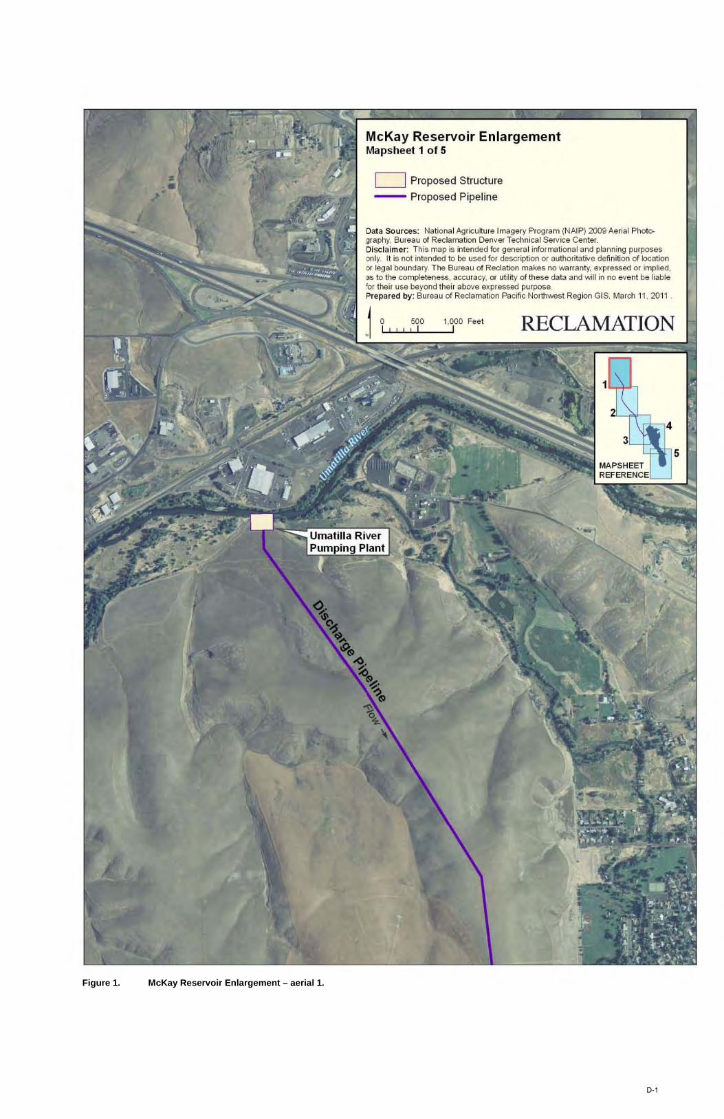
Pumping Facilities
As an option to the gravity pipeline, a pumping alternative was identified that would divert water from the Umatilla River near the city of Pendleton to the McKay Reservoir. This would require construction of a 175 cfs pumping plant on the Umatilla River downstream of Pendleton. The pumping plant would contain four horizontal centrifugal pumps.
The discharge system consists of a discharge pipeline with access holes (for inspection purposes) and a concrete outlet structure. The discharge pipeline is approximately 30,000 linear feet of 78-inch-diameter steel pipe (pumped flow of 175 cfs). The discharge pipeline will follow the approximate alignment shown in Figure 4, where the alignment travels southeast from the pumping plant and discharges into an outlet structure adjacent to McKay Dam. A bend near the end of the discharge line was included to align flows in the direction of the outlet structure. The outlet structure is surrounded by a riprap-lined spill area, which will convey the inlet flows down to the reservoir pool.
Final Umatilla Basin Water Supply Study 13
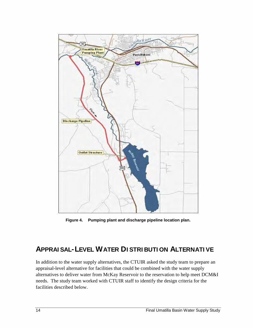
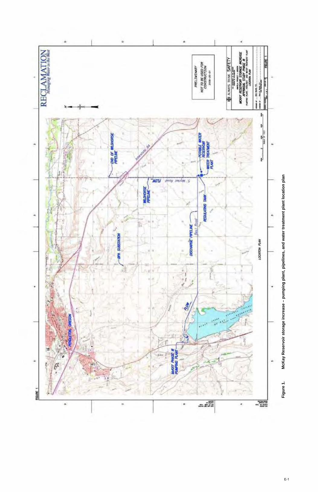
Figure 4. Pumping plant and discharge pipeline location plan.
APPRAISAL-LEVEL WATER DISTRIBUTION ALTERNATIVE
In addition to the water supply alternatives, the CTUIR asked the study team to prepare an appraisal-level alternative for facilities that could be combined with the water supply alternatives to deliver water from McKay Reservoir to the reservation to help meet DCM&I needs. The study team worked with CTUIR staff to identify the design criteria for the facilities described below.
Final Umatilla Basin Water Supply Study 14
CTUIR DCM&I SYSTEM
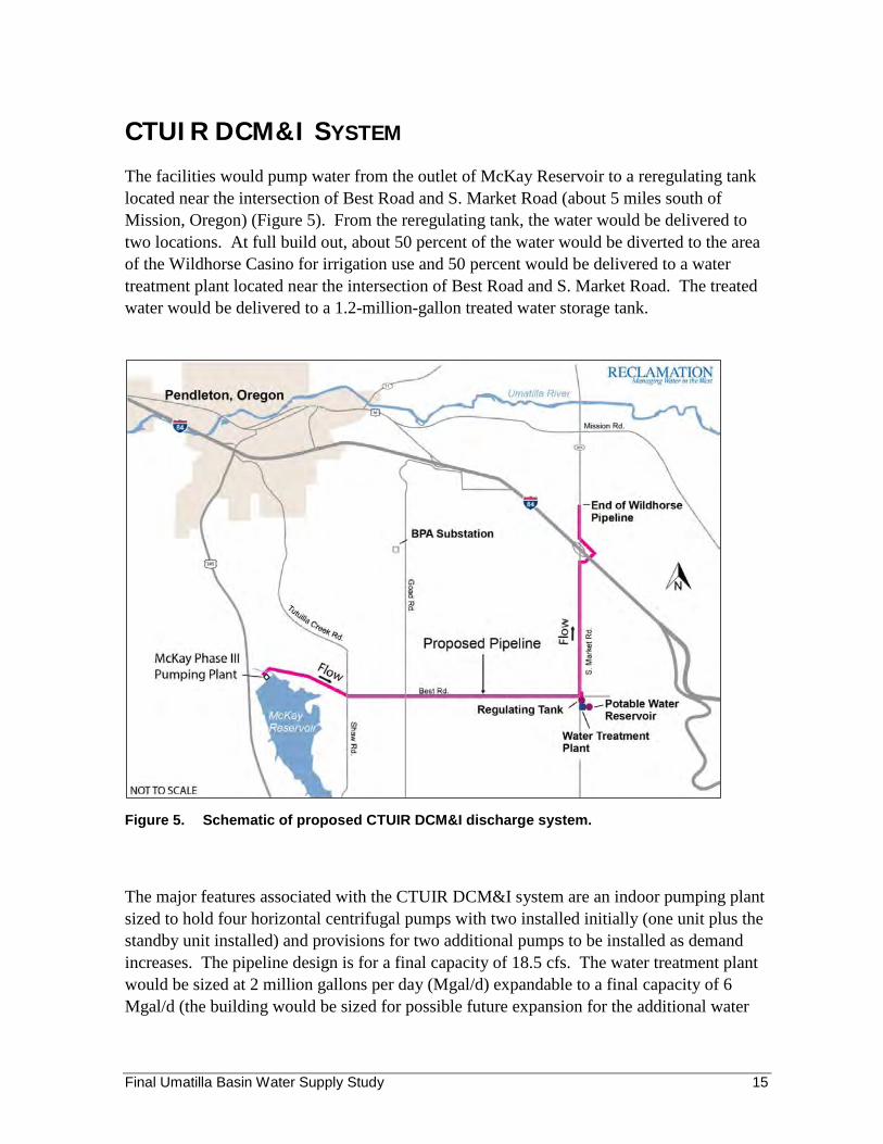
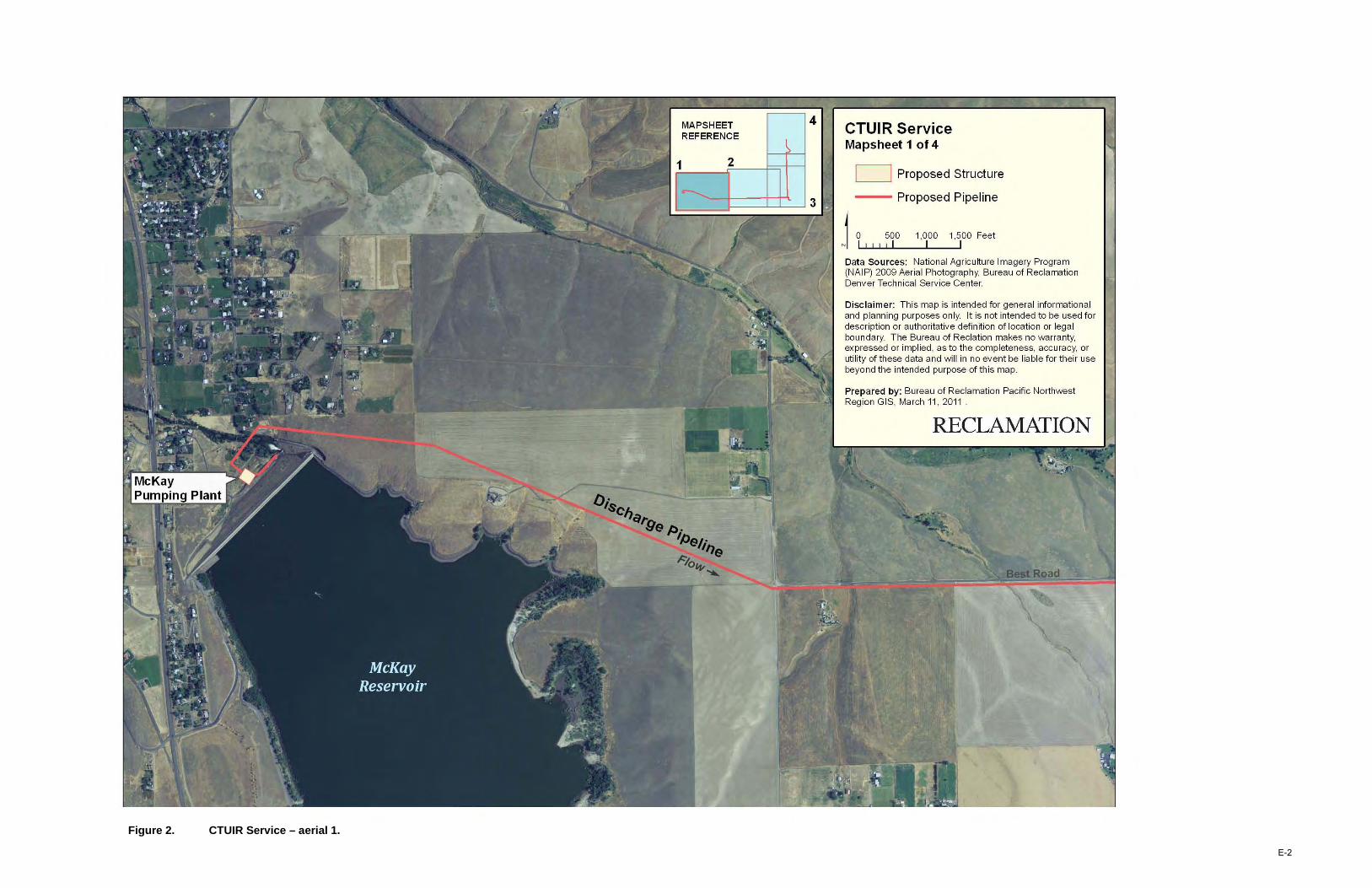
The facilities would pump water from the outlet of McKay Reservoir to a reregulating tank located near the intersection of Best Road and S. Market Road (about 5 miles south of Mission, Oregon) (Figure 5). From the reregulating tank, the water would be delivered to two locations. At full build out, about 50 percent of the water would be diverted to the area of the Wildhorse Casino for irrigation use and 50 percent would be delivered to a water treatment plant located near the intersection of Best Road and S. Market Road. The treated water would be delivered to a 1.2-million-gallon treated water storage tank.
Figure 5. Schematic of proposed CTUIR DCM&I discharge system.
The major features associated with the CTUIR DCM&I system are an indoor pumping plant sized to hold four horizontal centrifugal pumps with two installed initially (one unit plus the standby unit installed) and provisions for two additional pumps to be installed as demand increases. The pipeline design is for a final capacity of 18.5 cfs. The water treatment plant would be sized at 2 million gallons per day (Mgal/d) expandable to a final capacity of 6 Mgal/d (the building would be sized for possible future expansion for the additional water
Final Umatilla Basin Water Supply Study 15
treatment equipment).11 The treated water storage tank would be sized for a capacity of 1.2 million gallons.
A Bonneville Power Administration (BPA) substation located approximately 3 miles away could provide power to the facilities. The cost estimate assumes that BPA would furnish the power equipment needed to tap the line. This assumption would need to be re-evaluated during any future feasibility-level evaluation.
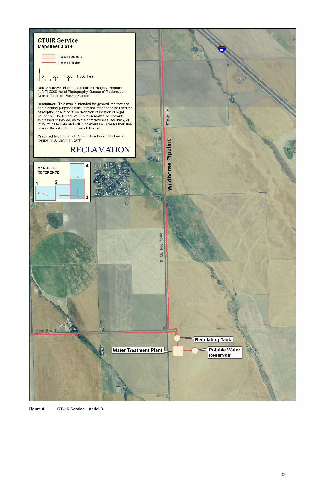
The discharge system consists of a discharge pipeline with access holes (for inspection purposes), divided into two reaches. The first reach is a 30-inch-diameter steel pipe that runs from the proposed McKay Reservoir pumping plant up to the intersection of Best Road and Shaw Road. From there, the pipeline follows Best Road to its intersection with S. Market Road. This approximately 29,000-foot-reach would discharge into a 15-foot-tall by 60-foot-diameter regulating tank located near the intersection of Best Road and S. Market Road. Water from this tank would flow into a water treatment plant or the pipeline leading to Wildhorse Casino.
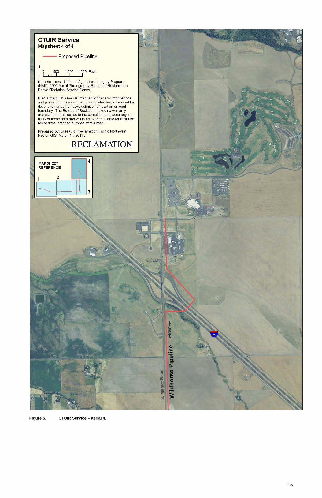
The second reach is an 18-inch PVC pipe that runs from the regulating tank north along S. Market Road to Interstate 84 (I-84). The pipe alignment then bends east to avoid the I-84 and S. Market Rd. intersection (to allow for simplified drilling operations and reduced cost) and then tends to the west to merge back into the alignment of S. Market Road, terminating near the Wildhorse Casino. This pipeline is designed so that it can be disinfected and used to carry potable water from the water treatment plant to the Wildhorse Casino area in the event future needs change.
Appendix E includes additional figures and layouts associated with the DCM&I system.
POTENTIAL RETURN FLOW IMPACTS RESULTING FROM
ALTERNATIVES
A monitoring program would be designed and put in place to identify return flow impacts resulting from implementing any of the alternatives (most notably the Feed Canal exchange). Impacts on downstream users (primarily WEID) would need to be quantified and, if significant, mitigated as required under the National Environmental Policy Act (NEPA). The cost estimates displayed in this report do not include an allowance for this potential mitigation program since current data is insufficient for design. Design of the monitoring program and any resulting mitigation measures would be addressed in conjunction with future feasibility-level evaluation of any of the alternatives in this report.
11 1 cfs = 0.0646315 Mgal/d
Final Umatilla Basin Water Supply Study 16
ALTERNATIVES BRIEFLY CONSIDERED BUT NOT
INCLUDED IN THIS STUDY
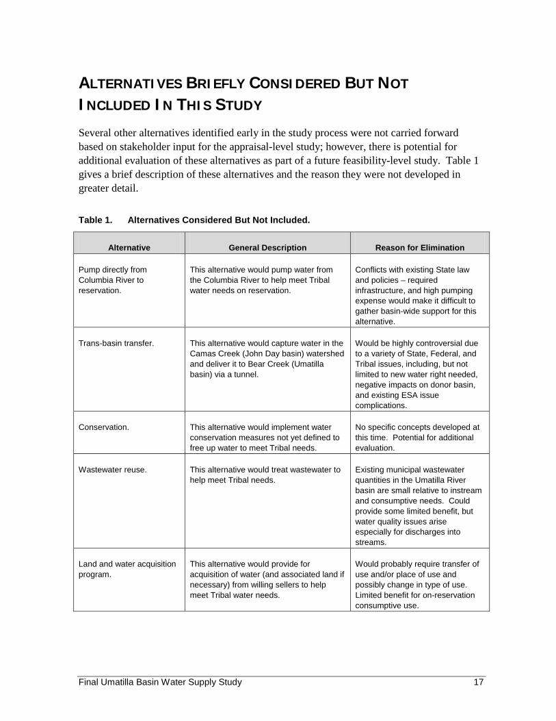
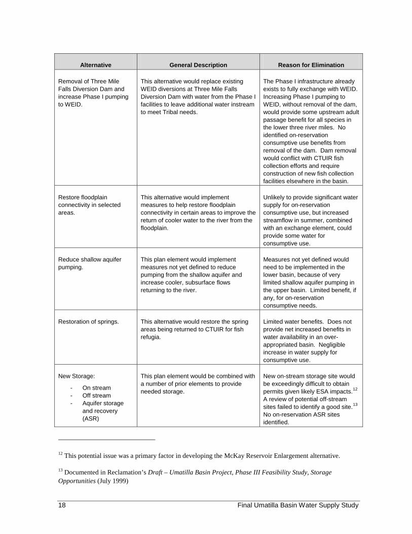
Several other alternatives identified early in the study process were not carried forward based on stakeholder input for the appraisal-level study; however, there is potential for additional evaluation of these alternatives as part of a future feasibility-level study. Table 1 gives a brief description of these alternatives and the reason they were not developed in greater detail.
Table 1. Alternatives Considered But Not Included.
Alternative General Description Reason for Elimination
Pump directly from This alternative would pump water from Conflicts with existing State law Columbia River to the Columbia River to help meet Tribal and policies – required reservation. water needs on reservation. infrastructure, and high pumping
expense would make it difficult to gather basin-wide support for this alternative.
Trans-basin transfer. This alternative would capture water in the Camas Creek (John Day basin) watershed and deliver it to Bear Creek (Umatilla basin) via a tunnel.
Would be highly controversial due to a variety of State, Federal, and Tribal issues, including, but not limited to new water right needed, negative impacts on donor basin, and existing ESA issue complications.
Conservation. This alternative would implement water conservation measures not yet defined to free up water to meet Tribal needs.
No specific concepts developed at this time. Potential for additional evaluation.
Wastewater reuse. This alternative would treat wastewater to help meet Tribal needs.
Existing municipal wastewater quantities in the Umatilla River basin are small relative to instream and consumptive needs. Could provide some limited benefit, but water quality issues arise especially for discharges into streams.
Land and water acquisition program.
This alternative would provide for acquisition of water (and associated land if necessary) from willing sellers to help meet Tribal water needs.
Would probably require transfer of use and/or place of use and possibly change in type of use. Limited benefit for on-reservation consumptive use.
Final Umatilla Basin Water Supply Study 17
Alternative General Description Reason for Elimination
Removal of Three Mile Falls Diversion Dam and increase Phase I pumping to WEID.
This alternative would replace existing WEID diversions at Three Mile Falls Diversion Dam with water from the Phase I facilities to leave additional water instream to meet Tribal needs.
The Phase I infrastructure already exists to fully exchange with WEID. Increasing Phase I pumping to WEID, without removal of the dam, would provide some upstream adult passage benefit for all species in the lower three river miles. No identified on-reservation consumptive use benefits from removal of the dam. Dam removal would conflict with CTUIR fish collection efforts and require construction of new fish collection facilities elsewhere in the basin.
Restore floodplain connectivity in selected areas.
This alternative would implement measures to help restore floodplain connectivity in certain areas to improve the return of cooler water to the river from the floodplain.
Unlikely to provide significant water supply for on-reservation consumptive use, but increased streamflow in summer, combined with an exchange element, could provide some water for consumptive use.
Reduce shallow aquifer pumping.
This plan element would implement measures not yet defined to reduce pumping from the shallow aquifer and increase cooler, subsurface flows returning to the river.
Measures not yet defined would need to be implemented in the lower basin, because of very limited shallow aquifer pumping in the upper basin. Limited benefit, if any, for on-reservation consumptive needs.
Restoration of springs. This alternative would restore the spring areas being returned to CTUIR for fish refugia.
Limited water benefits. Does not provide net increased benefits in water availability in an over-appropriated basin. Negligible increase in water supply for consumptive use.
New Storage:
- On stream - Off stream - Aquifer storage
and recovery (ASR)
This plan element would be combined with a number of prior elements to provide needed storage.
New on-stream storage site would be exceedingly difficult to obtain permits given likely ESA impacts.12
A review of potential off-stream sites failed to identify a good site.13
No on-reservation ASR sites identified.
12 This potential issue was a primary factor in developing the McKay Reservoir Enlargement alternative.
13 Documented in Reclamation’s Draft – Umatilla Basin Project, Phase III Feasibility Study, Storage Opportunities (July 1999)
Final Umatilla Basin Water Supply Study 18
COST ESTIMATES
Cost estimates used in appraisal-level studies determine whether a more detailed investigation of a potential project is justified. These estimates may be prepared from cost graphs, simple sketches, or rough general designs using the available site-specific design data. These estimates are intended to be used as an aid in selecting the most economical plan by comparing alternative features such as dam types, dam sites, canal or transmission line routes, and powerplant or pumping plant capacities.
Appraisal cost estimates are not suitable for requesting project authorization or construction fund appropriations from the Congress due to the early stage of project development.
The cost estimates presented below reflect the design and construction sequence following authorization and availability of appropriations:
• Year 1 – Collection of design data, preparation of supplemental NEPA documentation (if needed)
• Years 2 and 3 – Preparation of designs and specifications, and contract award
• Years 4 through 9 – Construction
The January 2010 price-level appraisal-level cost estimate ranges shown in Table 2 address construction of the facilities discussed in this report, including operation and maintenance (but not replacement costs). They do not include on-reservation improvements necessary to effectively distribute and use the irrigation water supply. In addition, they do not include the cost of infrastructure necessary to deliver potable DCM&I water from the storage tank to the service area or the infrastructure necessary to distribute water within the yet undefined service area. Only the projected power costs associated with the various alternatives are shown. The O&M and power estimates do not reflect the likely reduction in pumping costs that would be anticipated with the implementation of exchange agreements.
Finally, the O&M cost estimates do not currently include an allowance for the potential increased costs of administering the water measurement, water rights/transfers, and exchange agreement(s) that could be associated with implementing one of the alternatives. That allowance would be estimated as part of assessing alternatives once operational criteria has been sufficiently developed as part of future evaluations.
Final Umatilla Basin Water Supply Study 19

Table 2. Umatilla Basin Water Supply Study Cost Summary
Alternative Current Estimated
Yield (acre-feet)
Jan 2010 Price Level Appraisal Construction Cost
Range
Jan 2010 Annual
O&M Cost
Jan 2010 Annual
Power Cost
Jan 2010 Price Level Annual Equivalent Cost Range
Jan 2010 Price Level Cost per Acre-foot
Low High Low High Low High
WID Full Exchange 65,000 $370,000,000 $440,000,000 $1,470,000 $2,180,000 $19,190,000 $22,120,000 $300 $340
WID Partial Exchange 18,300 $120,000,000 $145,000,000 $470,000 $690,000 $6,200,000' $7,250,000' $340' $400'
HID - Full Exchange for Feed Canal Diversions
38,000 $0 $0 $560,000 $842,000 $1,402,000' $1,402,000' $40* $40*
HID - Maxwell Canal Exchange
18,500 $35,000,000 $41,000,000 $270,000 $410,000 $2,150,000' $2,400,000' $120' $130'
McKay Reservoir Enlargement
34,400 $70,000,000 $85,000,000 N/A N/A $2,940,000 $3,570,000 $90 $100
Gravity Canal/Pipeline (175 cfs)
34,400 $365,000,000 $435,000,000 $130,000 N/A $15,330,000 $18,260,000 $450 $530
Umatilla River Pumping Plant & Discharge Pipeline (175 cfs)
34,400 $245,000,000 $280,000,000 $380,000 $670,000 $11,340,000 $12,810,000 $330 $370
Facilities to Deliver Water from McKay Reservoir for Reservation DCM&I and Irrigation Use (including 2 Mgal/d Treatment Plant)
3,500 $105,000,000 $125,000,000 $590,000 $260,000 $5,260,000 $6,100,000 $1,500 $1,740
* Does not include an allocated portion of the construction obligation associated with the existing Phase II facilities.
Final Um
atilla Basin Water Supply Study
20

APPENDICES


APPENDIX A WID FULL EXCHANGE FIGURES AND LAYOUTS
WesUand Diyerslon Full Pump Exchange F~"1 015
______ ,...,xno _ _ ."""---_ .... -~_ .. _r __ _ ., .. _._ .. __ ... -..-......... -~ .. -"'-.. -_ .. _ .. _" ....... _-"" -.. - ....... --.-.. ~ .. --~- ..... -...... ~ .. -.. -.. -~--.. -- .... --~- ... .... _ ... _ ... ---_.,, _ .. ___ .,.z _'1100>
RECLAMlnlON
Figure 1. WID Full Exchange – aerial 1.
A-1
o ~. c_, ..... "11
~ .... -_ _ ._~ __ I'o:9'''IW'l!Ol);_ ",-".aG& ___ ~...,,_
--"-'--- " .. _._ .. _--_ ......... -~ .. -"'-~..-_"_"IoiO'_ !lIo ..... ____ "-_ .. __ "'_~_ .. _ .. b
... --"""" ..... -..... ~"'-.. _ .. _,,_ .. __ ""' __ b_ ... ..... _ ... __ ... _-_"" _ .. ____ IIS
_,1_ ;-.. "C,'''',-... ,,, .... ---;,'''',----.. ,,'.
RECIJ\MATION
Figure 2. WID Full Exchange – aerial 2.
A-2
o ~. C_ ...... 1'11
f'IpoaIo , "'~ R_"''''',~ _ 1 _ _ ........ _ ......... ,....,:MlOII _ _ u;;Go;,_~ __ ..,. _ __ oI_r_~ - , .. _._ .. __ ......... -..., ..... _."._ ... _ .. -_ .. _ ..... _ ""' ..... ......, ....... Tho
-"'--"'--"-"~ ... -,- .. ...., ..... -"" ... ~ .. -.. _ .. _ .. _ .. _- ""'--,,-..... _ ... __ ... _-RECLAMATION
Figure 3. WID Full Exchange – aerial 3.
A-3

o ~. CaNI ...... Og
Pipolnt.~~ RM .... " ... I>' _ _ _ _ Ig __ "'<9 ... ~l«I6_ "--"'1.SGS ___ \IKlI ..... _ __ .,_f __ _ ""_._b __ ... """, _ .... ..... _ ... _ .. _ .. -_ .. _ ..... -, ....... _-""' -'''--'''--''-'''' h __ ....... <1 ... _ ..... ~"'_ .. --_ .. _ .. _- ""--,,--..... _ ... __ ... _-_"", _ .. _ ... ___ 115 _11_
.~
RECu\MATION
Figure 4. WID Full Exchange – aerial 4.
A-4
Westland Diversion Full Pump Exchange Figure 5 of 5
Canal , existing
Pipeline. proposed ~ Reservoir. proposed
Oala SO\lr~es: tlaoonalAgncullure Im<lg('ly PrOQlatfl (!/AIP) 2006 Aenal PhoIog:~hy. USGS r~1OIIaI ~oIog!C Oa\a~ (!<HO) Hog, ResoIut>::In FlowIIle, Bureau ofRedamallOll Faalibes Dataset
(lK(lalmer: This map IS If1leoded 101 genefal.,formi!llooal aJld pOOmog purposes 001)' 11 IS nolllllended 10 be used for demlpllon 01 autMlltalrle defiN'oo ofloca!!Of'l 01 legal boorodary 1M IS r,ol a surve, prod.oct The Bureau of RedamatlOO makes no _ranly expressed OI~, as 10 h compieteM5s. atCUlOCY Of~~I I1V of "IS datil and .. ;W m I'IOllW11lbe liable for U5eOl mrs-lJSlE! oIflese data Thrsawlles bof11O IIIdrJIliJaI use 01 me data and sggregale use w,,, othel 001<1
Prepned by: Bureau ofRedarnallOn Pocafic No!thwesl Reg.onGlS, December 12. '}fJJ7
RECLAMATION
Figure 5. WID Full Exchange – aerial 5.
A-5

APPENDIX B WID PARTIAL EXCHANGE FIGURES AND LAYOUTS
I
Westland Diversion Partial Pump Exchange FiOu~ 1 014
_ ,n,,_._" __ n _ _ """ I .... _~ .. _br_~..-_ .. _ .... _, ...... .....,""""''''' _~ __ ... __ ._ .. b
... --"oWj" ... --.. ~ .. - .. _ .. _,,_rJ __ "" __ ~_ ....
......... ------_""' _ .. ___ ~(lI!; _.=
.'---<>"'-<,., ... ,=~"." ... "---,., ... ,=~".,, .. " RECLAMATION
Figure 1. WID Partial Exchange – aerial 1.
B-1
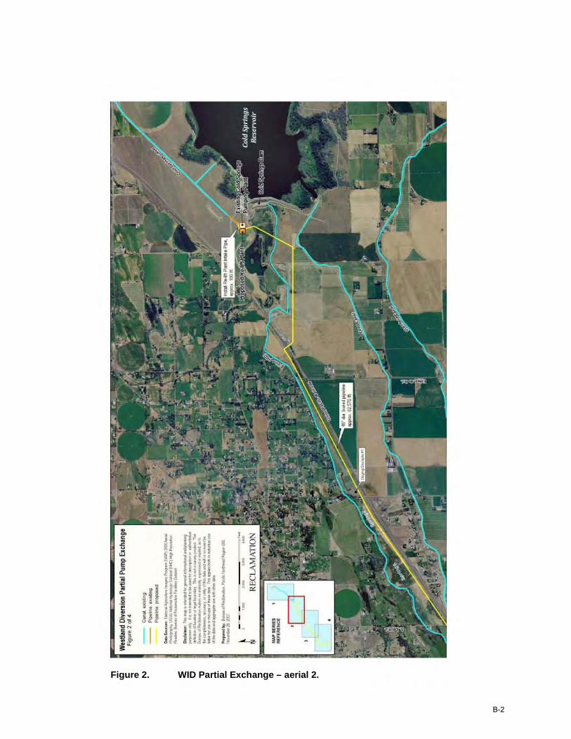
Figure 2. WID Partial Exchange – aerial 2.
B-2
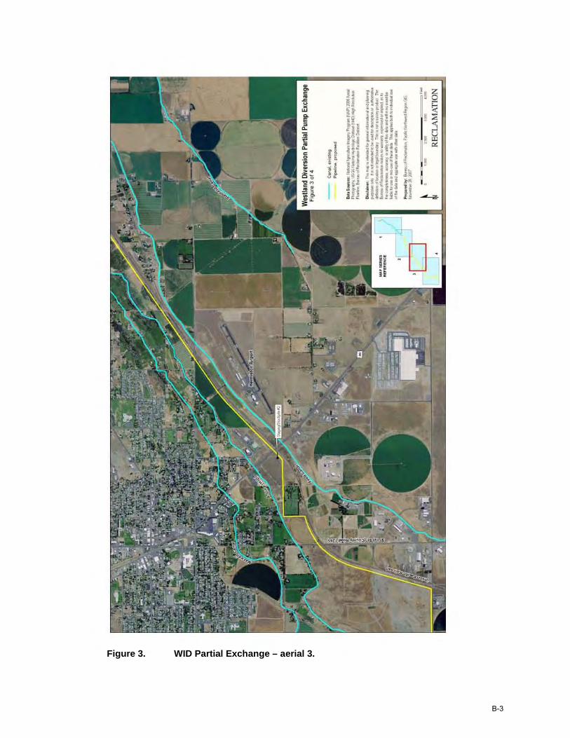
Figure 3. WID Partial Exchange – aerial 3.
B-3
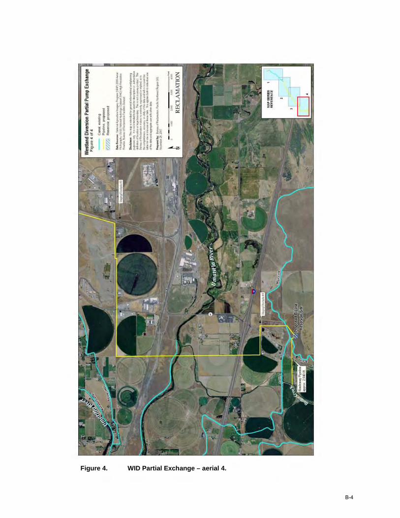
Figure 4. WID Partial Exchange – aerial 4.
B-4

APPENDIX C HID EXCHANGE LAYOUTS

MAP SERIES REFERENCE
,
Maxwell Canal Full Exchange Figure 1 of 4 (plain schematic)
Canal, Lined Canal, Unlined
_ Canal, Defective Liner Pipeline Drainage Ditch, Pond Perimeter
Data Sources: ESRI, Herrriston I rr'o:lation Diol ri;l USGS Nati rn al I-tjdrcj ogic Dlt ffi et (NHD) Hi rtl ResolLtiJn FIClM lle, Bureau cl Reel <rnatioll
Disclaimer: This map i3 Iltended for general information" and pl oonllg purposes Ill~ It is mt Ilte rded to be used for descriil i:ln or aLt mrialr. e defi rition of ucatlJn or leg it bo un dary. His is net a sUfley iJ'oduct ~ Bure"-l of Reclam1t i:Jn mlks no v.a rra rty, expressed or ~ i ed, as to Ire co~leteres5, aGCtlraGj', or uti ity of thil data and wi l in no m~nt be li oo le for LEe or mis-lISe oft rese data. This 14lPi es I:MJth to ind il ilti al use of the da ta am aoo regate lI3e ~th oth er data
Prepared by: Bureau cl Redarnatiol\ Pocific N crl tJ/oiest Regi rn Q S, AUgLBt 18,::ros
RECLAMATION
Figure 1. Schematic of the HID Exchange – view 1.
C-1
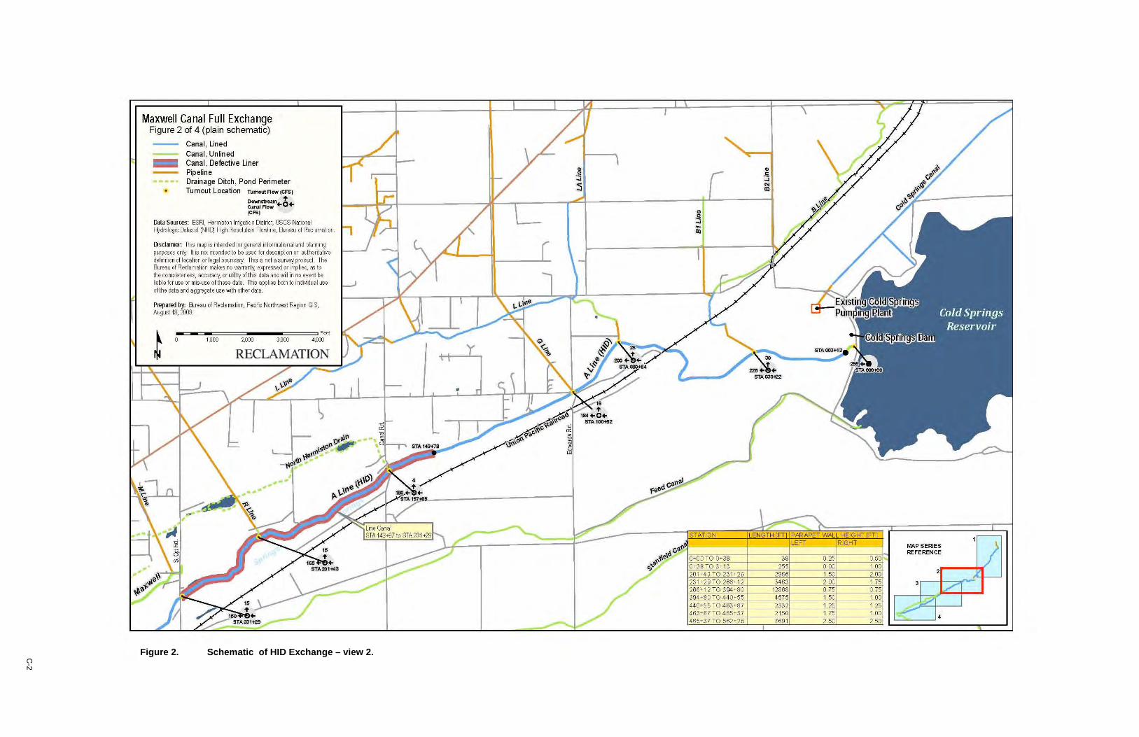
Maxwell Canal Full Exchange Figure 2 of 4 (plain schematic)
Canal, Lined Canal, Unlined
_ Canal, Defective Liner Pipeline Drainage Ditch, Pond Perimeter Turnout Location TUmoutFlow(CFS)
Downstream O~ Canal Flow + + (CFS)
Data Sources: ESRJ, Hermd on Irrigation Dd~t, USGS National f-ildrolo gic Datas et (~q Hgh Resolution Flo>M ine, BJreau of Rec lamation
Disclaimer: Th ~ map is intend ed for general informational and planning purposes on~ It ~ not intended to be wed fordescription or authoritat rve definition of location or legal boundary T h~ ~ not a survey prodLXt. The Bureau of Rec lam ation makes no warranty, expressed or impli ed, ffi to the completeness, accurac y, or utility of this data and will in no event be liabl e for me or mS-L13e of these dat a. Ths appli es both to indMdual me of the data and aggregate lISe with other data
Prepared by: BJreau of Rec la mation, PocifK: Northwest Reg ion GIS, Aug llSt 18, X03
~~~~==~~ __ ~~==~ effi 1,000 2,000 3,000 4 ,000 t RECLAMATION
MAP SERIES REFERENCE
C-2
Figure 2. Schematic of HID Exchange – view 2.
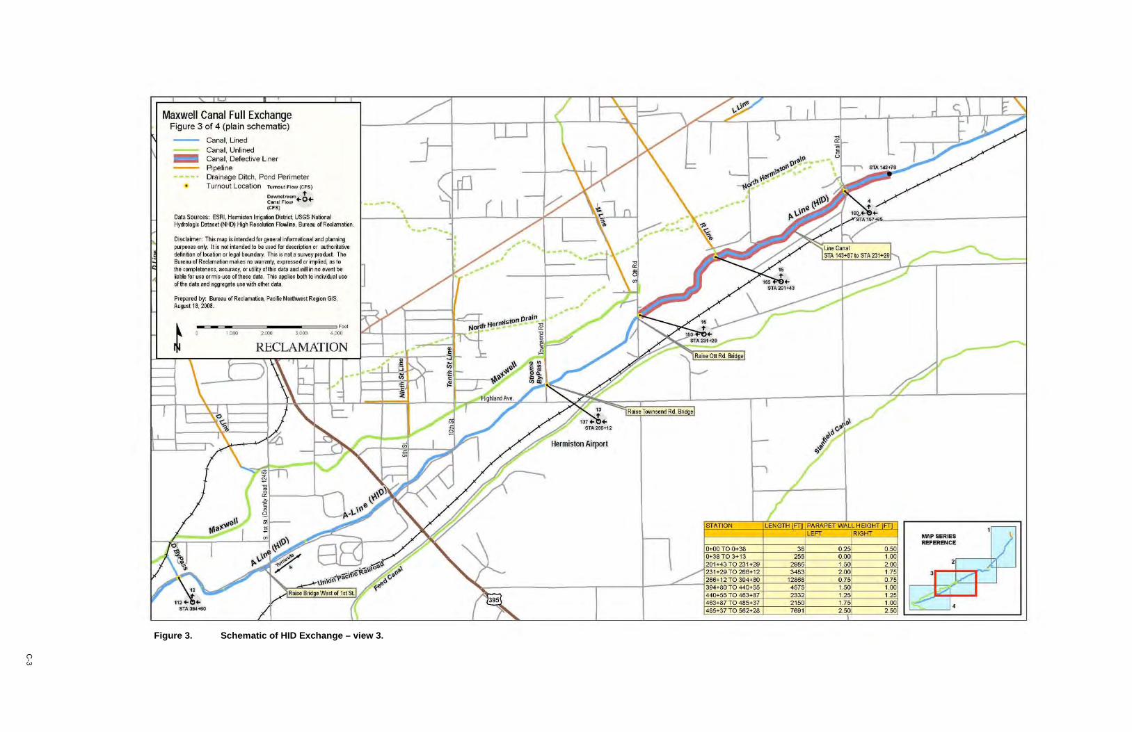
Maxwell Canal Full Exchange Figure 3 of 4 (pla in schematic)
Canal, Lined Canal, Unlined
_ Canal, Defective L ner Pi peli ne Drainage Ditch , Pond Perimeter Turnolit Location T1Jmo ut Flow ICFSj
Dowl1It "..., .,. C..,.I Flow +0+ (CFS)
Data Soofces: ESRI. H. rmistm 1m;lIIion [);dritt USGS Notiona l Hydrologic Data.et (tW) l-'ign Resol.Jtion FloWine, 8~e i>ll olR$CI;Y!1i'lio:lrl.
Di sclarner: Th ill map ;. nend ed lor geM r. informational and planni ng pIIfI)Os" onft. It il r>lI i1te nded to be , .. d lor de",~tion Or JllJtn oriillivo definitio n cllo<ation or lega l b<uJdary. Thi ... nol I .,,..oy prodl.d. The S"'e!llI of RllClllmation mak e. no W1lnlriy. exp res.ed or "'Plied, IS to th e c~l el"" e'$, accuracy, or utilly ofthi . data iIfld .. l;" no ._t be bble fo r us. ormil-.nl ol tn ••• data. This SWIllS both to in dMdu.1 u'. ol lh . data and _ggrlgate us. wilh other data.
Prepared by: Bur'all rJ Reclamation, Pac(1C Nortiwiest Region GIS, Auguot ,a, 200a.
-... <= .. <=.,,,~~~,,., ...... .,,,~~~,, , .. o 1.0 00 2(00 3 000 40Q(l t RECLAMATION
•
.' .......... ' ...... I ·,
..' .' "
,
\
MAP SERIES REFERENCE
., 'I ;:>t --fJ •
C-3
Figure 3. Schematic of HID Exchange – view 3.
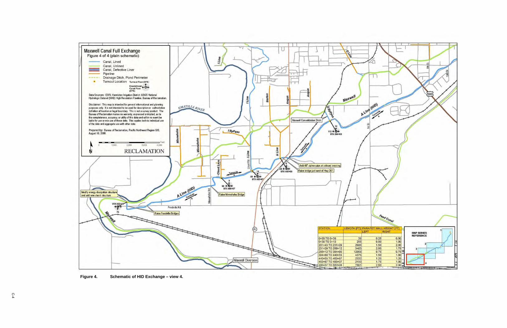
Maxwell Canal Full Exchange Figure 4 of 4 (plain schematic)
- Carlal, Lined Carla l, Uni ned
_ Canal, Defective liner
Pipeline Drainage Ditch, Pond Perimeter Turnout location 'fI.>m.,," ~Iow (CFS)
Down", .. ", .. c!, .. C.nol Flow (eFS)
Data So urces: ESRI, Hemi,ton Img." ()istr;c~ USGS NIIIion . ' Hyd "' '' g ~ Data,ot (I<HJ) i'tgI1 FI .. oI~on FI"""". , 8L11'I '" ot R .. hrnll!iort
Ois(larner: Thi , map ;' i1t. nd &d 1(11' II' n ~1M in foml.1tionallW'ld pta rri-lg p....,. •• on~. ~ is not irte n~ to b. ",,0<1 for descf1,tio n or • .-:horitatiY. dMi .... n a1locoti"" Of " go! boiJndarf. Tri. is not. wrw1 product TM s... •• u of Rodon1 l11ion milk •• ..., ...,.rty, ul' ...... d O[ mpi od. IS t. til. COl'l1!l ~ttr1.u, . cC\.Qcy, or uti ity of this dlila ..,d ';1 i1 no evert be r"bI . for lI$l or miHIt olm ... dati. Thi$ ilII'pin both til 0!d;'; du/l11M ofh da ta .,d .Wagat ...... ,.;1:1'1 other dlltl.
"'ep<wed by: ell''''lt rJ RlclamlJtion, Paek No.ttl'",,,t R.gi(ln GIS, " ,-," U, I Ie, 2008
~ ,~
~ 0 '.COO ~'~CL~ZtATl~~
v/ f:;;;;;;; ---- ,,-_._ .'
~
-
~ "r • ~
~
t-
~.
~ Fr;e:!";)e R:I
.MII .8ridge.1
~
~'i·" 1 .,
" /
§ j
"'-' J : ~ ~
"
y
"\.
~I
-'" ~ /
T PARAPETWALlHElGffT FT LEFT RIGHT PMP SERIES
I REFEREI'ICE
, , i.<'
®1 1~ I. B
C-4
Figure 4. Schematic of HID Exchange – view 4.
MAP SERIES REFERENCE
2r----b(
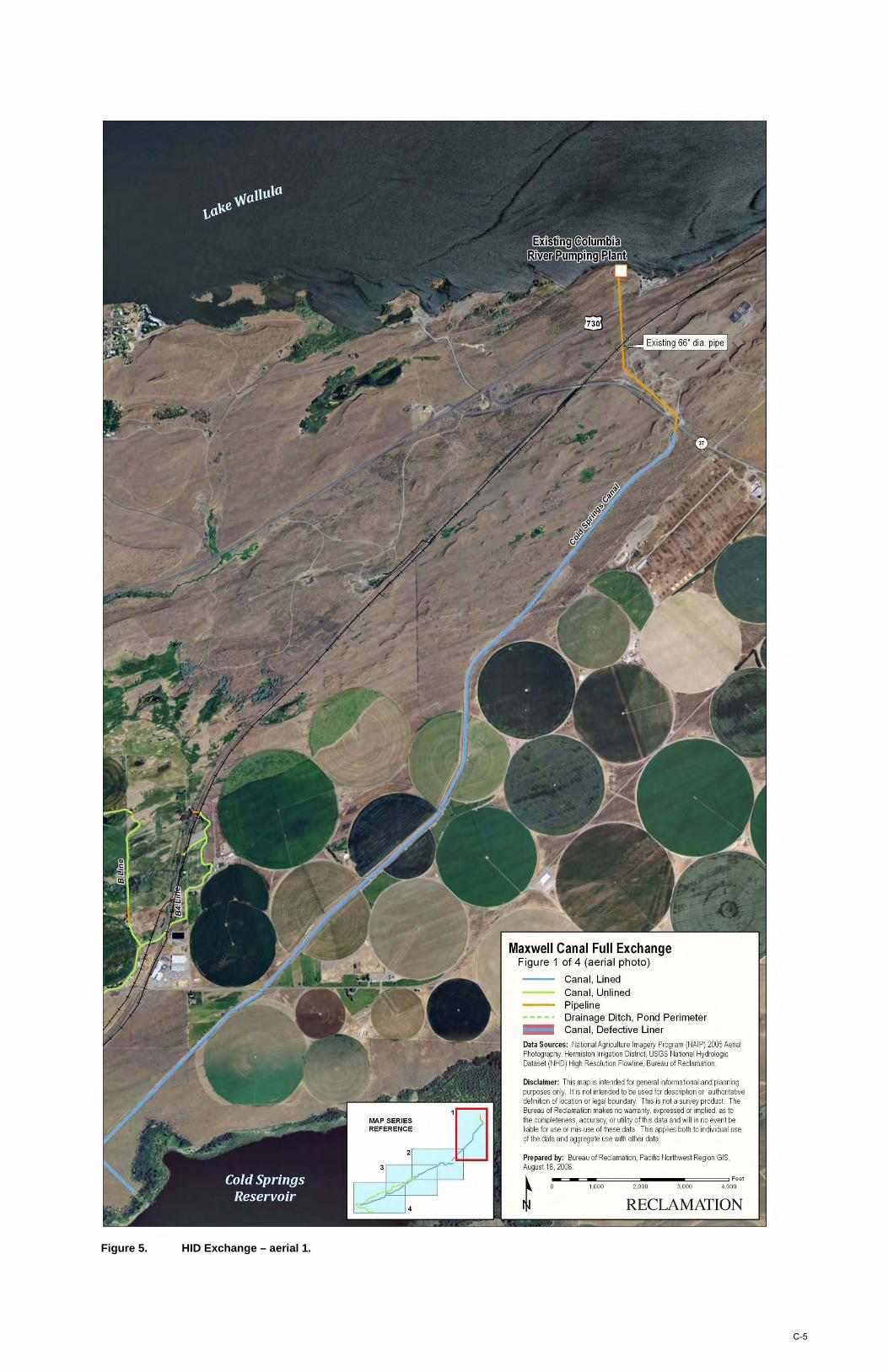
Maxwell Canal Full Exchange Figure 1 of 4 (aerial photo)
Canal, Lined Canal, Unlined Pipeline Drainage Ditch, Pond Perimeter
_ Canal, Defective Liner
Data Sources: National Agriculture Imagery Program (NAIP) 2006 Aerial Photography, Hermiston Irrigation District, USGS Nalional Hydrologic Dataset (NHD) High Resolution Flowline, Bureau of Reclamation.
Disclaimer: This map is intended for general informational and planning purposes only. It is not intended to be used for description or authoritative definition of location or legal boundary. This is not a survey product The Bureau of Reclamation makes no warranty, expressed or implied, as to the completeness, accuracy, or utility of this data and will in no event be liable for use or mis-use of these data. This applies both to individual use of the data and aggregate use with other data.
Prepared by: Bureau of Reclamation , Pacific Northwest Region GIS, August 18, 2008.
_=~~~===~ ____ ==== Feet 1.000 2.000 3.000 4.000
RECLAMATION
Figure 5. HID Exchange – aerial 1.
C-5
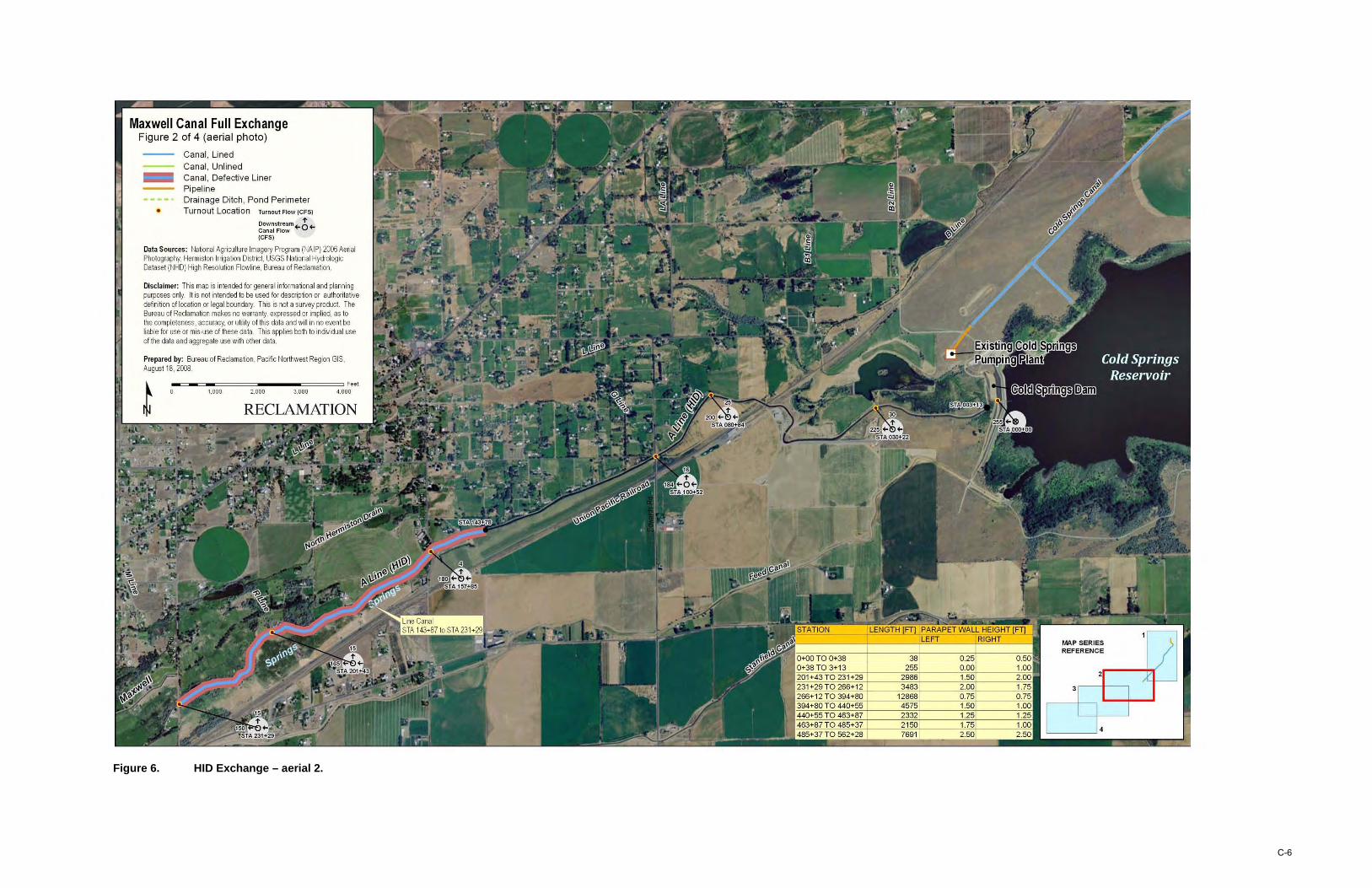
Maxwell Canal Full Exchange Figure 2 of 4 (aerial photo)
Canal , Lined Canal , Unlined
_ Canal , Defective Liner Pipeline Drainage Ditch, Pond Perimeter Turnout Location Turnout Flow (CFS)
Downstream +-6+Canal Flow (CFS)
Oata Sources: Na tional Agricul ture Imagery Program (NAIP) 2006 Aerial Photography, Hermiston Irrigalion District, USGS National Hydrologic Dataset (NHD) High Resolution Flowline, Bureau of Reclamation .
Disclaimer: This map is Intended for general informational and planning purposes only. II is not intended \0 be used for description or authoritative definition of location or legal boundary. This is not a survey product. The Bureau of Reclamation makes no warranty, expressed or implied, as to the completeness, accuracy, or utili ty of this data and will in no event be liable for use or mis-use of these data. This applies both to individual use of the data and aggregate use with other data
Prepared by: Bureau of Redamation, Pacific Northwest Region GIS. August 18. 2008.
:-=-~,·,O~O"O===2",O"O~O---3·,O~O"O===4'C.O:aeet
MA P SERIES REFERENCE
Figure 6. HID Exchange – aerial 2.
C-6
Maxwell Canal Full Exchange Figure 3 of 4 (aeria l photo)
Canal, Lined Canal, Unlined
_ Canal, Defective Liner Pipeline Drainage Ditch , Pond Perimeter
• Turnout Location Turnout Flow (CFS)
Downstream+- 6+Canal Flow (CFS)
Oata Sources: National Agriculture Imagery Program (NAIP) 2006 Aerial Photography, Hermiston Irrigation District, USGS National Hydrologic Dataset (NHO) High Resolution Flowline, Bureau of Reclamation .
Disclaimer: This map is intended for general informational and planning purposes only_ II is not intended to be used for description or authoritative definition of location or legal boundary. This is not a survey produc\. The Bureau of Reclamation makes no warranty, expressed or implied, as to the completeness, accuracy, or utility of this data and will in no event be liable for use or mis-use of these data. This applies both to individual use of the data and aggregate use wi th other data.
Prepared by: Bureau of Reclama tion , Pacific Northwest Region GIS, August 18, 2008 .
.. => .. =o-c======== .......... ========oFeet 1,000 2,000 3,000 4.000
MAP SERIES REFERENCE
2
"
Figure 7. HID Exchange – aerial 3.
C-7
Maxwell Canal Full Exchange Figure 4 of 4 (aerial photo)
Canal, Lined Canal , Unlined
_ Canal, Defective Liner Pipeline Drainage Ditch, Pond Perimeter Turnout Location Turnout Flow (CFS)
Down stream~6~ Canal Flow (CFS)
Data Sources: National Agriculture Imagery Program (NAIP) 2006 Aerial Photography, Hermiston Irrigation District, USGS National Hydrologic Dataset (NHO) High Resolution Flowline, Bureau of Reclamation.
Disclaimer: This map is intended for general informational and planning purposes only_ It is not intended to be used for description or authoritative definition of location Of legal boundary. This is not a survey product The Bureau of Reclamation makes no warranty, expressed or implied, as to the completeness , accuracy, or utility of this data and will in no evenl be liable for use or mis-use of these data. This applies both to individual use of the data and aggregate use with other data.
Prepared by: Bureau of Reclamation, Pacific Northwest Region GIS, August 18, 2008 .
.. ~ .. =--c======== .......... ========oFeet 1,000 2,000 3,000 4.000
MAP SERIES REFERENCE
2
4
Figure 8. HID Exchange – aerial 4.
C-8
APPENDIX D MCKAY RESERVOIR ENLARGEMENT
FIGURES AND LAYOUTS
McKay Reservoir Enlargement Mapsheet 1 of 5
D Proposed Structure Proposed Pipeline
Data SOurces: Nationa l Agriculture Imagery Program (NAIP) 2009Aeria l Photography, Bureau at Reclamation Denver Technical Service Center. Disclaimer: This map is intended for genera l jnformational and planning purposes only. It is not intended to be used for description or authoritative definition of k1cation Of legal boundary. The Bureau of Reclalion makes no warranty, expressed or implied, as to the completeness, accuracy. Of utility of these data and INiII in no event be tiable 'or their use beyond their above expressed purpose. Prepared by: Bureau of Reclamation Pacific Northwest Region GIS, March 11, 2011,
o 500 1.000 Feel
~':::~~' :':,;;;~~' RECLAMATION
Figure 1. McKay Reservoir Enlargement – aerial 1.
D-1
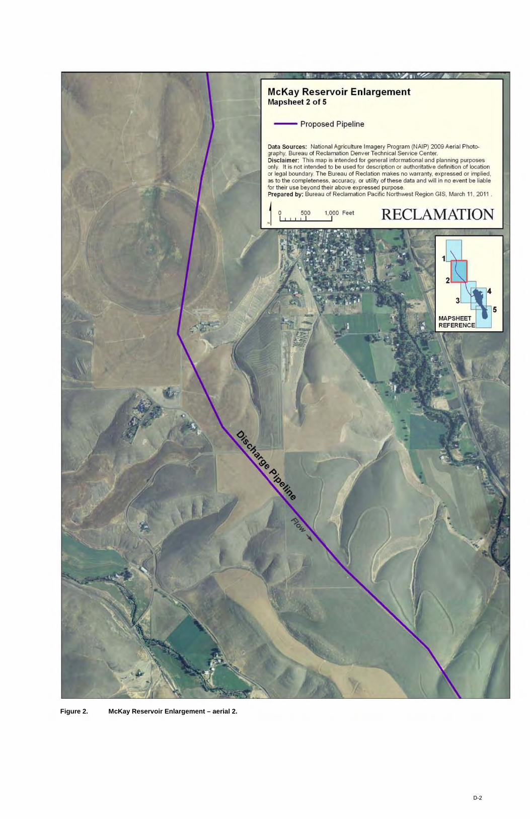
McKay Reservoir Enlargement Mapsheet 2 of 5
-- Proposed Pipeline
Data Sources: Nationa l Agriculture Imagery Program (NAIP) 2009Aeria l Photo. gr3phy, Bureau of Reclamation Denver Technical Service Center. Disclaimer: This map is intended for genera l informational and planning purposes only. It is nol intended to be used for description or authoritative definition of location or legal boundary. The Bureau of Reclation makes no warranty, expressed or implied. as to the completeness, accuracy. or utility of these data and will in no event be l iable 'or their use beyond their above expressed purpose. Prepared by: Bureau of Reclamation Pacific Northwest Region GIS, March 11. 2011,
~ 0 500 1.000 Feet .1 "' .J...J ....... ~I ~' __ --"
RECLAMATION
Figure 2. McKay Reservoir Enlargement – aerial 2.
D-2
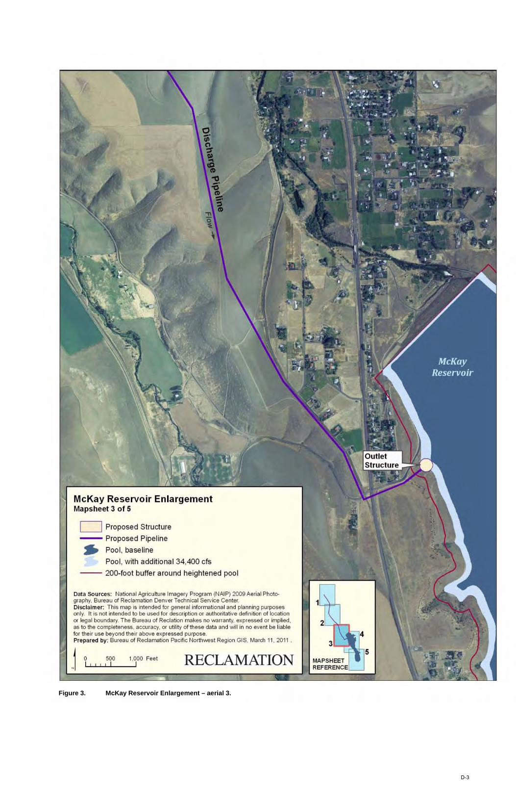
McKay Reservoir Enlargement Mapsheet 3 of 5
D Proposed Structure
-- Proposed Pipeline
~ Pool, baseline
Pool , with additional 34,400 cfs
-- 200-foot buffer around heightened poot
Data Sources: Nationa l Agriculture Imagery Program (NAIP) 2009 Aeria l Photography, Bureau of Reclamation Denver Technical SelVice Center. Disclaimer: This map is intended for genera l informational and planning purposes only. It is not intended to be used for description or authoritat ive definition of location or legal boundary. The Bureau of Reclal ion makes no warranty, e~pressed or implied, as to the completeness, accuracy, or utility of these data and wi ll in no event be liable for their use beyond their above expressed purpose. Prepared by: Bureau of Reclamation Pacific Norlh'M3st Region GIS, March 11, 201 1 .
o I
500 , I
1.000 Feet I RECLAMATION
2,,--1'''''''
3
MAPSHEET REFERENCE
Figure 3. McKay Reservoir Enlargement – aerial 3.
D-3
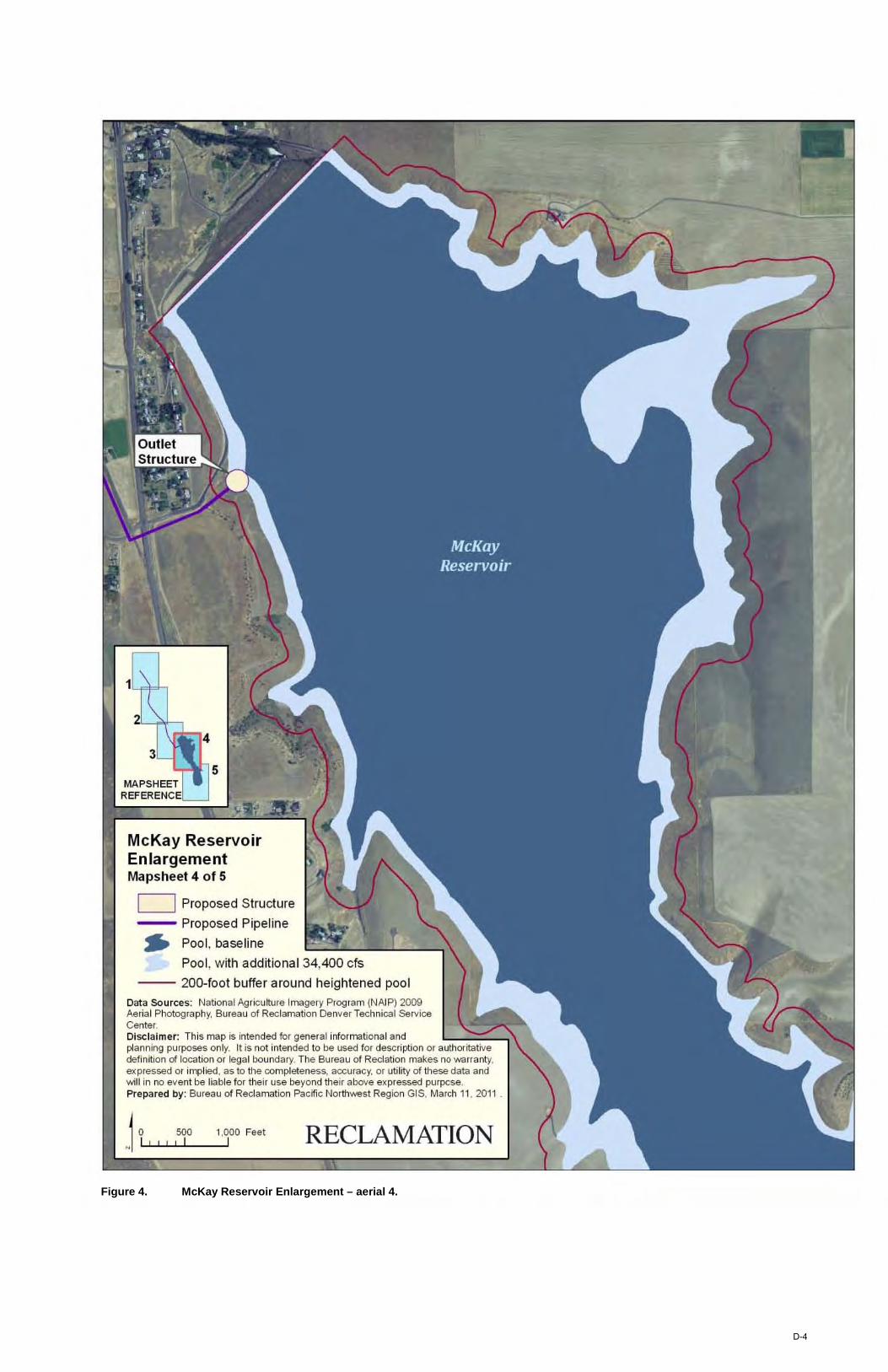
McKay Reservoir Enlargement Mapsheet 4 of 5
D Proposed Structure
-- Proposed Pipeline .. Pool, baseline
Pool , with addit ional 34,400 cfs
-- 200-foot buffer around heightened pool Data Sources: Nationa l Agricu lture Imagery Program (NAIP) 2009 Aerial Photography, Bureau of Reclamation Denver Technical Service Center. Disclaimer: This map is intended for genera l informational and planning purposes only. It is not intended to be used for description or authoritative definition of location or legal boundary. The Bureau of Reclation makes no warranty. e)(pressed or implied. as to the completeness, accuracy, or utility of these data and will in no event be liable for their use beyond their above expressed purpcse. Prepared by: Bureau of Reclamation Pacific North'Nesl Region GIS, Ma rch 11 , 201 1 _
I,QOO Feet I RECLAMATION
Figure 4. McKay Reservoir Enlargement – aerial 4.
D-4

2Lfh
McKay Reservoir Enlargement Overview
~ Pool, baseline
Pool , with additional 34,400 cfs
-- 200-foot buffer around heightened pool
Data Sources: Nationa l Agriculture Imagery Program (NAIP) 2009 Aerial Photography. Bureau of Reclamation Denver Technical Service Center. Disclaimer: This map is intended tor genera l informational and planning purposes only. It is not intended to be used for description or authoritative definition of location or legal boundary. The Bureau of Reclation makes no warranty. expressed or i mpl~d . as 10 the completeness, accuracy, or utility of these data and "";11 in no event be liable for their use beyond their above expressed purpose. Prepared by: Bureau of Reclamation Pacific Northwest Region GIS, March 11. 201
1,000 Feet I RECLAMATION
Figure 5. McKay Reservoir Enlargement – aerial 5.
D-5

1.
McK ay ReselVQir Enlargement Overview
D P reposed Structure
-- P reposed P ipeli re
... Pool, baseline
Pool, wth additional 34,400 cfs
-- 200-foot buffer around heightened poo I
Olta $ OlJ"C~ I : tlat)) Iii L0f,) rtl nll-e Imaga IV P IJgriiTl N, •. IP 2009 ,.~ r1a1 Pl ot:>gr'll ly, 61f€~1 c<t ~cl'ln<rtbl De luer1l! c ll tal~ 'J~ Ce l~ r. C4 IC lal m ~r: n ~ In 'V ~ II~ 1(led Dr ge I erall11Onn~tbl ~~ I a Id pl~lllIg P "IXlIU 011 . IU l ot • ~ HlHI to Ile H€(IDr (l! ~crll1b1 0 r a lUo rIt1tt,le denl II) I c<t !)(l'Itb I o r I?gail lol Id.~ FI"- Tie 6 I f€iI I 01 Rec liltb I mal:e ~ 10 !A'a Ifal V, exp ~ ~se ( 1 or In pll!d, a> nUe compl!te l eu,accHiI:){.ol Inllr 01l1e~e d.'It.~ald ·AIIIII 10 eue Itile Il'll l l! D r Ue Ir I $e Il€"-(O 1(1 Ue Ir aooue e xp reHe d p Ilpo~e . FT"B pa~ d b l' : B !rea I c<t f).> cl'tm~1b1 Pacn~ No rtlwe, t Reg!) I G IS, r,l~ ~I II, <lJ ll .
~ 0 0.5 ... 1 I I I I I I RECLAMATION
Figure 6. McKay Reservoir Enlargement – overview.
D-6

APPENDIX E CTUIR ON-RESERVATION DCM&I SYSTEM
FIGURES AND LAYOUTS
,
"-""f--'
, ,
) "',
• ,. , ,/ -
.J. I /
! ,
-t -, ,
,
I
-,
,
, -' , ~
, •
,
,
, " , ' ,/
'I
/'
.. "
./.
I I, , !I' n l i
I ,
~ ,
I
I -
•
I
,
-~ I, ,
E-1
Figu
re 1
. M
cKay
Res
ervo
ir st
orag
e in
crea
se –
pum
ping
pla
nt, p
ipel
ines
, and
wat
er tr
eatm
ent p
lant
loca
tion
plan
CTUIR Service Mapsheet 1 of 4
D Proposed Structure
--- Proposed Pipeline
1 a 500 1,000 1,500 Feet N ~I~!~!~!~!~I ____ ~I ____ ~I Data Sources: National Ag riculture Imagery Prog ram (NAIP) 2009 Aerial Photog raphy, Bureau of Reclamation Denver Technical Service Center.
Disclaimer: This map is intended for general informational and planning purposes onl y. It is not intended to be used for description or authoritative definition of location or lega l boun da ry. The Burea u of Reclation makes no wa rr anty, expressed or implied, as to the completeness, accuracy, or utility of these data and will in no event be liable for their use beyond the intended purpose of this map.
Prepared by: Burea u of Recla mation Pacific Northwest Reg ion GIS, March 11 ,2011 .
RECLAMATION
Figure 2. CTUIR Service – aerial 1.
E-2
CTUIR Service Mapsheet 2 of 4
- Proposed Pipeline
980 1,4 70 Fee1 I I
Data Sources: National Agriculture Imagery Program (NAIP) 2009 Aerial Photography, Bureau of Reclamation Denver Technica l Service Center.
Disclaim er: This map is intended for general informational and planning purposes on ly. It is not intended to be used for description or authoritative definition of location or legal boundary. The Bureau of Reclation makes no warranty, expressed or implied, as to the completeness, accuracy, or utility of these data and wi ll in no event be liable for their use beyond the intended purpose of this map.
Prepared by: Bureau of Reclamation Pacific Northwest Region GIS, March 11, 2011 .
RECLAMATION
MAPSHEET REFENCE
1 2
4
Best Road
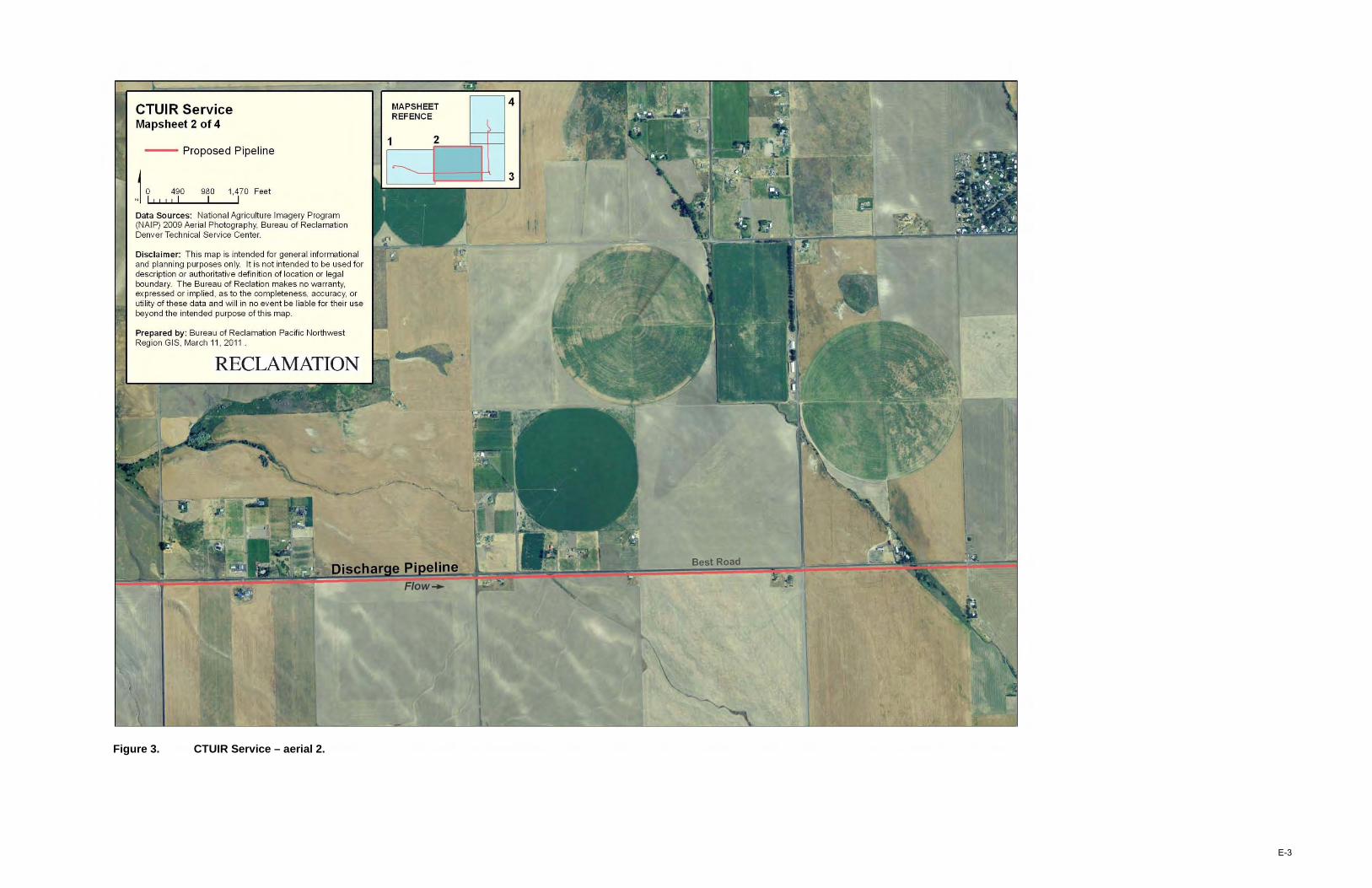
Figure 3. CTUIR Service – aerial 2.
E-3
CTUIR Service Mapsheet 3 of 4
Proposed Stru cture
--- Proposed Pipeline
1 a 500 1,000 1,500 Feet N LI~!~!~!~I ____ -LI ____ ~I
Data Sources: National Ag riculture Imagery Prog ram (NAIP) 2009 Aerial Photog raphy, Bureau of Reclamation Denver Technica l Service Center.
Disclaimer: This map is intended for general infor mational and planning purposes only. It is not intended to be used for description or author itative definiti on of location or lega l boundary. The Burea u of Reclation makes no wa rranty, expressed or implied, as to the completeness, accuracy, or utility of these data and w ill in no event be liable for their use beyond the intended purpose of this map.
Prepared by: Burea u of Recla mation Pacific Northwest Reg ion GIS, March 11, 2011 .
RECLAMATION
Regulating Tank
Potable Water Reservoir
..
Figure 4. CTUIR Service – aerial 3.
E-4
CTUIR Service Mapsheet 4 of 4
--- Proposed Pipeline
j ~ " ! :~o 1,000 1,500 Feet I I
Data Sources: National Ag riculture Imagery Prog ram (NAIP) 2009 Aerial Photog raphy, Bureau of Reclamation Denver Technica l Service Center.
Disclaimer: This map is intended for general informational and planning purposes only. It is not intended to be used for description or authoritative definiti on of location or lega l boundary. The Bureau of Reclation makes no wa rranty, expressed or implied, as to the completeness, accuracy, or utility of these data and will in no event be liable for their use beyond the intended purpose of this map.
Prepared by: Bureau of Recla mation Pacific Northwest Reg ion GIS, March 11 ,2011 .
MAPSHEET REFERENCE
2
RECLAMATION
4
3
Figure 5. CTUIR Service – aerial 4.
E-5