umd20000 rev b - pc-4000 user manual 800.654.2027 fax 260.489.5683 3 introduction purpose panoramic...
TRANSCRIPT

www.pancorp.com | 800.654.2027
Model: 801125-5/801125-6
User Manual© Copyright 2007 Panoramic Corporation
UMD2000 Rev B

phone 800.654.2027 www.pancorp.com fax 260.489.56832
Table of Contents
Introduction ______________________________________________________________________________3-5 Purpose ___________________________________________________________________________________________ 3 Statement of Compatibility ___________________________________________________________________________ 3 Warning of Voltage Regulators ________________________________________________________________________ 5 X-Ray Shielding Requirements ________________________________________________________________________ 5 Intended Use ______________________________________________________________________________________ 5
Symbols & Defi nitions _______________________________________________________________________ 6
PC-4000 Components _______________________________________________________________________ 7
PC-4000 Labeling ___________________________________________________________________________ 8
PC-4000 Pre-Patient Setup _________________________________________________________________9-11 Prepare The Patient ________________________________________________________________________________ 10 Position The Patient ________________________________________________________________________________ 11
PC-4000 Patient Positioning _____________________________________________________________________ 11-12 Set The kVp _______________________________________________________________________________________ 11 Position The Patient ________________________________________________________________________________ 11 Recheck Patient Positioning _________________________________________________________________________ 12 Take The Exposure _________________________________________________________________________________ 12 Release The Patient ________________________________________________________________________________ 12 Digital Image Enhancement _____________________________________________________________________ 13-14 Image Processing __________________________________________________________________________________ 13 User Image Process ________________________________________________________________________________ 14 Setting Up the Image Repository _____________________________________________________________________ 14
PC-4000 TMJ Pre-Patient Setup _____________________________________________________________________ 15 PC-4000 TMJ Patient Positioning _________________________________________________________________ 16-19 Set The kVp _______________________________________________________________________________________ 16 Position The Patient _____________________________________________________________________________ 16-17 Recheck Patient Positioning _________________________________________________________________________ 18 Take The Exposure _________________________________________________________________________________ 18 Release The Patient _____________________________________________________________________________ 18-19
Panoramic Radiography ______________________________________________________________ Appendix A
Maintenance Schedule _______________________________________________________________ Appendix B
PC-4000 Labeling ___________________________________________________________________ Appendix C
PC-4000 Specifi cations _______________________________________________________________ Appendix D
PC-4000 Space Requirements _________________________________________________________ Appendix E
PC-4000 (MVT1000) _________________________________________________________________ Appendix F
phone 800.654.2027 www.pancorp.com fax 260.489.56833
Introduction
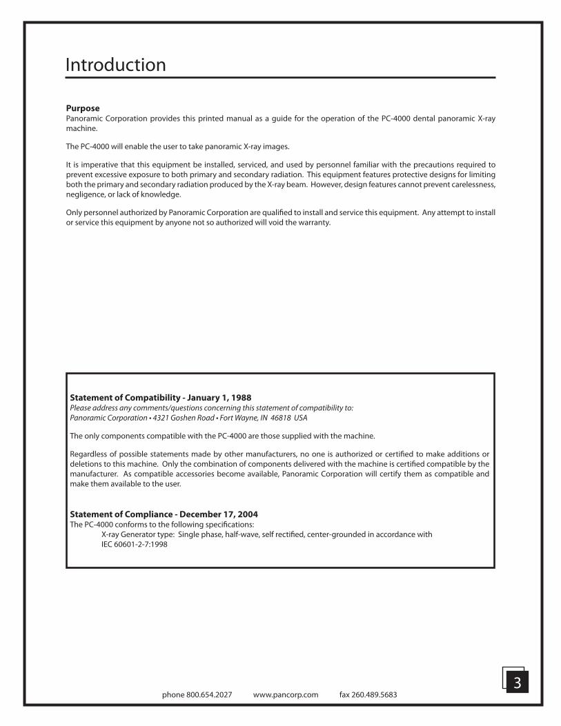
PurposePanoramic Corporation provides this printed manual as a guide for the operation of the PC-4000 dental panoramic X-ray machine.
The PC-4000 will enable the user to take panoramic X-ray images.
It is imperative that this equipment be installed, serviced, and used by personnel familiar with the precautions required to prevent excessive exposure to both primary and secondary radiation. This equipment features protective designs for limiting both the primary and secondary radiation produced by the X-ray beam. However, design features cannot prevent carelessness, negligence, or lack of knowledge.
Only personnel authorized by Panoramic Corporation are qualifi ed to install and service this equipment. Any attempt to install or service this equipment by anyone not so authorized will void the warranty.
Statement of Compatibility - January 1, 1988Please address any comments/questions concerning this statement of compatibility to:Panoramic Corporation • 4321 Goshen Road • Fort Wayne, IN 46818 USA
The only components compatible with the PC-4000 are those supplied with the machine.
Regardless of possible statements made by other manufacturers, no one is authorized or certifi ed to make additions or deletions to this machine. Only the combination of components delivered with the machine is certifi ed compatible by the manufacturer. As compatible accessories become available, Panoramic Corporation will certify them as compatible and make them available to the user.
Statement of Compliance - December 17, 2004The PC-4000 conforms to the following specifi cations: X-ray Generator type: Single phase, half-wave, self rectifi ed, center-grounded in accordance with IEC 60601-2-7:1998

phone 800.654.2027 www.pancorp.com fax 260.489.56834
Introduction
Safety(Class B Device; Shock, Fire, Casualty)
• IEC 60601-1 Medical Electrical Equipment - Part 1: General Requirements for Safety• IEC 60601-1:1998 + A1:1991 + A2:1995 Medical electrical equipment - Part 1-1: General requirements for safety Collateral
standard: Safety requirements for medical electrical systems• IEC 60601-2-7:1998 Medical electrical equipment - Part 2-7: Particular requirements for the safety of high-voltage
generators of diagnostic X-ray generators• IEC 60601-2-28:1993 Medical electrical equipment - Part 2: Particular requirements for the safety of X-ray source assemblies
and X-ray tube assemblies for medical diagnosis• IEC 60601-2-32:1994 Medical electrical equipment - Part 2: Particular requirements for the safety of associated equipment
of X-ray equipment• EN 60601-1:1990 + A1:1993 + A2:1995 + A3:1996 Medical electrical equipment - Part 1-1: General requirements for
safety - Collateral standard: Safety requirements for medical electrical systems• CAN/CSA C22.2 NO. 601-1-M90 + A1:1994 + A2:1998 Medical Electrical Equipment - Part 1: General Requirements for
Safety
X-Ray Evaluation• IEC 60601-1-3:1994 Medical electrical equipment - Part 1: General requirements for safety - 3. Collateral standard:
General requirements for radiation protection in diagnostic X-ray equipment
Software Review• IEC 60601-1-4:1996 + A1:1999 Medical electrical equipment - Part 1-4: General requirements for safety - Collateral
Standard: Programmable electrical medical systems
EMC(Class B Device):
• EN 60601-1-2:2001 (IEC 60601-1-2:2001) Medical electrical equipment - Part 1-2: General requirements for safety - Collateral standard: Electromagnetic compatibility - Requirements and tests
• EN 55011:1998 + A1:1999 + A2:2002 Industrial, scientifi c and medical (ISM) radio-frequency equipment - Radio disturbance characteristics - Limits and methods of measurement
• EN 61000-3-2:2000 Electromagnetic compatibility (EMC) - Part 3-2: Limits - Limits for harmonic current emissions (equipment input current <= 16 A per phase)
• EN 61000-3-3:1995 + A1:2001 Electromagnetic compatibility (EMC) - Part 3-3: Limits - Limitation of voltage changes, voltage fl uctuations and fl icker in public low-voltage supply systems, for equipment with rated current <= 16 A per phase and not subject to conditional connection
• EN 60601-1-2:2001 (IEC 60601-1-2:2001) Electromagnetic Compatibility - Requirements and Tests• EN 61000-4-2:1995 + A1:1998 + A2:2001 (IEC 1000-4-2) Electromagnetic compatibility (EMC)- Part 4-2: Testing and
measurement techniques - Electrostatic discharge immunity test• EN 61000-4-3:2002 (IEC 1000-4-3) Electromagnetic compatibility (EMC) - Part 4-3: Testing and measurement techniques
- Radiated, radio-frequency, electromagnetic fi eld immunity test• EN 61000-4-4:1995 + A1:2001 + A2:2001 (IEC 1000-4-4) Electromagnetic compatibility (EMC) - Part 4-4: Testing and
measurement techniques - Electrical fast transient/burst immunity test • EN 61000-4-5:1995 + A1:2001 (IEC 1000-4-5) Electromagnetic compatibility (EMC)- Part 4-5: Testing and measurement
techniques - Surge immunity test• EN 61000-4-6:1996 + A1:2000 (IEC 1000-4-6) Electromagnetic compatibility (EMC) - Part 4-6: Testing and measurement
techniques - Immunity to conducted disturbances, induced by radio-frequency fi elds• EN 61000-4-8:1993 + A1:2001 (IEC 1000-4-8) Electromagnetic compatibility (EMC) - Part 4-8: Testing and measurement
techniques - Power frequency magnetic fi eld immunity test• EN 61000-4-11:1994 + A1:2001 (IEC 1000-4-11) Electromagnetic compatibility (EMC) - Part 4-11: Testing and measurement
techniques - Voltage dips, short interruptions and voltage variations immunity tests

phone 800.654.2027 www.pancorp.com fax 260.489.56835
Voltage Regulator WarningDo not plug this machine into ANY voltage regulating device. Contact Panoramic Corporation with any questions regarding this.
X-ray Shielding RequirementsThe requirements for panoramic and cephalometric shielding for building, operator, and patient, depend on state and local regulations. Contact your state Department of Health for compliance information. Compliance could involve a blueprint review, facility check, wall construction, fi lm badge implementation, remote switch installation, and/or a lead apron. It is beyond the scope of this manual to advise on these regulations.
Intended UseAn extraoral source X-ray system is an AC-powered device that produces X-rays and is intended for dental radiographic examination and diagnosis of diseases of the teeth, jaw and oral structures.
Warning StatementsWarning: This X-ray unit may be dangerous to patient and operator unless safe exposure and operating instructions are observed.
During installation, machine is leveled to the fl oor. Do not move/transport the machine before contacting Panoramic Corporation Service Department at (800)654-2027.
Notice: Ground reliability can only be acheived when this equipment is connected to a hospital only or hospital grade receptacle.
The use of accessory equipment not complying with the equivalent safety requirements of this equipment may lead to a reduced level of safety of the resulting system. Consideration relating to the choice of accessory equipment shall include:• use of the accessory in the patient vicinity• evidence that the safety certifi cation of the accesory has been performed in accordance to the appropriate IEC 60601-1
and/or IEC 60601-1-1 harmonized national standard.
Portable and mobile RF Communications equipment can aff ect medical electrical equipment.
Original document created in English.
Panoramic Corporation requires anyone moving or transporting their machine to contact the service Department at (800)
654-2027.
phone 800.654.2027 www.pancorp.com fax 260.489.56836
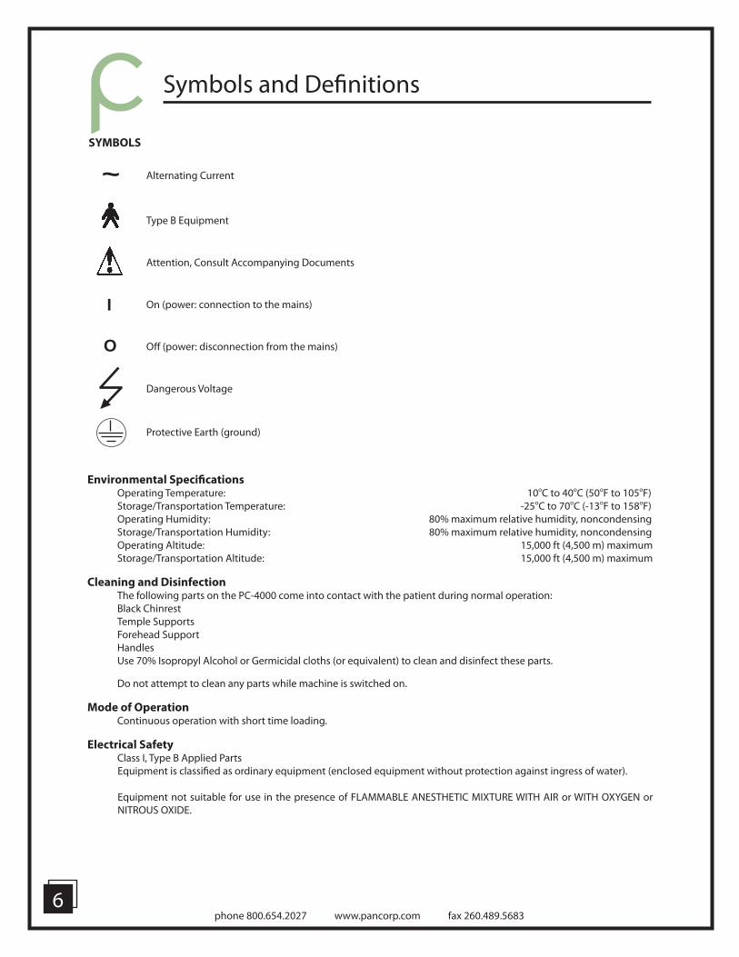
SYMBOLS
Alternating Current
Type B Equipment
Attention, Consult Accompanying Documents
On (power: connection to the mains)
Off (power: disconnection from the mains)
Dangerous Voltage
Protective Earth (ground)
~
I
O
Symbols and Defi nitions
Environmental Specifi cations Operating Temperature: 10oC to 40oC (50oF to 105oF) Storage/Transportation Temperature: -25oC to 70oC (-13oF to 158oF) Operating Humidity: 80% maximum relative humidity, noncondensing Storage/Transportation Humidity: 80% maximum relative humidity, noncondensing Operating Altitude: 15,000 ft (4,500 m) maximum Storage/Transportation Altitude: 15,000 ft (4,500 m) maximum
Cleaning and Disinfection The following parts on the PC-4000 come into contact with the patient during normal operation: Black Chinrest Temple Supports Forehead Support Handles Use 70% Isopropyl Alcohol or Germicidal cloths (or equivalent) to clean and disinfect these parts.
Do not attempt to clean any parts while machine is switched on.
Mode of Operation Continuous operation with short time loading.
Electrical Safety Class I, Type B Applied Parts
Equipment is classifi ed as ordinary equipment (enclosed equipment without protection against ingress of water).
Equipment not suitable for use in the presence of FLAMMABLE ANESTHETIC MIXTURE WITH AIR or WITH OXYGEN or NITROUS OXIDE.
phone 800.654.2027 www.pancorp.com fax 260.489.56837
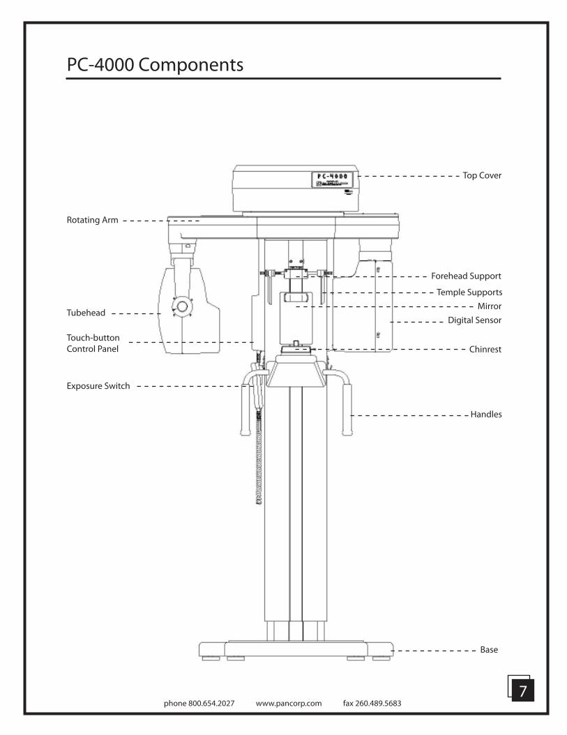
PC-4000 Components
Base
Top Cover
Temple Supports
Forehead Support
Mirror
Digital Sensor
Chinrest
Handles
Rotating Arm
Tubehead
Touch-button Control Panel
Exposure Switch

phone 800.654.2027 www.pancorp.com fax 260.489.56838
PC-4000 Labeling
+
Exposure
Indicator
Allows you to
scroll to the
next screen
Allows you to
move back one
screen, and
after exposure,
allows user
to reset the
rotating arm
Moves machine up
in the user mode and
scrolls up the menu’s
in-service mode
Moves machine down
in the user mode and
scrolls down the menu’s
in-service mode
Accepts fl ashing
value or move
to program to
next screen
Turns machine
on and off
Allows user to
select function
or increase
value
Allows user to
select function
or decrease
value

phone 800.654.2027 www.pancorp.com fax 260.489.56839
PC-4000 Pre-Patient Setup
1. Press POWER on the front of the control panel. The screen will now display: PANORAMIC
CORPORATION
2. Press MODE The screen will now display: SELECT OPERATION
PAN L
(Select from TMJ L, TMJ R, Pan L or Pan R)To scroll, press the Adjust buttons (+) , (-) to select the function you wish to use.
3. Press ENTER after the selection is made. 4. Press MODE to move to the next screen The screen will now display: ARM NOT POSITIONED
or ARM POSITIONED
5. If not positioned, press ENTER. The rotating arm will now reset to the “home” position for the operation you have selected.
6. Press MODE to move to the next screen The screen will now display your selected operation: PAN L
KVP: 80.0 (the number will be fl ashing)
7. Select the correct panoramic rotation direction from the software screen on the Dell computer. The software must match the setting on the panoramic units control panel.
Example: PC-4000 Program Selection

phone 800.654.2027 www.pancorp.com fax 260.489.568310
PC-4000 Pre-Patient Setup
8. Using the knob at the rear of the forehead support, adjust the forehead support toward the mirror to allow room for positioning the patient.
9. Slide the temple supports apart to allow room for positioning the patient’s head.
10. Using the UP/DOWN switch on the control panel, adjust the chinrest arm until it is slightly higher than the patient’s chin. This will ensure that the patient stands up as straight as possible.
11. If a stool is to be used, place the stool so that the seat is centered under the chinrest. This will help ensure that the patient’s neck is straight.
Prepare The Patient1. Ask the patient to remove any metal objects, such as glasses, earrings, removable dentures, hearing aids, hair pins, neck chains, bib chains, and collar zippers from their head and neck area. These objects can prevent X-rays from reaching the sensor, causing poor diagnostic-quality images.
2. If a lead apron is used, and a panoramic poncho is not available, place the lead apron on the patient’s back. Ensure that it does not cover the back of the neck. As the tubehead rotates around the patient, the X-rays pass through the head at a slight upward angle. This allows the X-ray beam to pass through the skull more effi ciently by avoiding the denser area of the patient’s skull.
3. Guide the patient into the PC-4000. Use the UP/DOWN buttons on the control panel to adjust the chinrest arm until it is slightly higher than the patient’s chin. This will ensure that the patient is standing up as straight as possible.
Caution: It is the responsibility of the operator to ensure no
obstructions exist during column movement due to surroundings
and/or patient. Movement can be terminated by releasing the
UP/DOWN buttons.
4. Have the patient hold onto the handles and move his/her feet under the chinrest. This will help ensure that the patient’s neck is straight. 5. Place the appropriate chinrest on the permanent, black chinrest on the chinrest arm:
a. Small Child – Removable, black plastic chinrest may be needed to allow the child’s forehead to reach the forehead support.
b. Adolescent and Adult – No additional chinrest. Majority of patients require no additional chinrest.
c. Edentulous – Removable, clear plastic chinrest. Aids in centering and consistently positioning the patient.
phone 800.654.2027 www.pancorp.com fax 260.489.568311
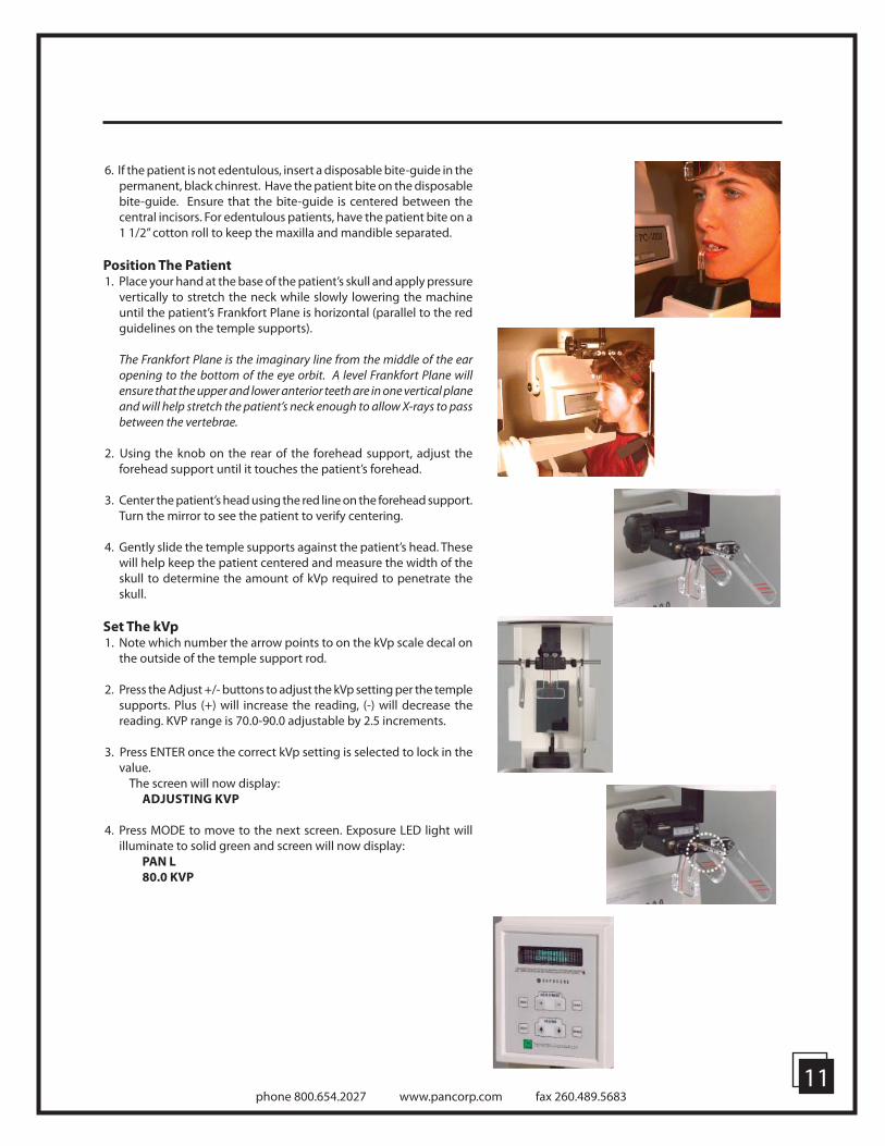
6. If the patient is not edentulous, insert a disposable bite-guide in the permanent, black chinrest. Have the patient bite on the disposable bite-guide. Ensure that the bite-guide is centered between the central incisors. For edentulous patients, have the patient bite on a 1 1/2” cotton roll to keep the maxilla and mandible separated.
Position The Patient1. Place your hand at the base of the patient’s skull and apply pressure
vertically to stretch the neck while slowly lowering the machine until the patient’s Frankfort Plane is horizontal (parallel to the red guidelines on the temple supports).
The Frankfort Plane is the imaginary line from the middle of the ear opening to the bottom of the eye orbit. A level Frankfort Plane will ensure that the upper and lower anterior teeth are in one vertical plane and will help stretch the patient’s neck enough to allow X-rays to pass between the vertebrae.
2. Using the knob on the rear of the forehead support, adjust the forehead support until it touches the patient’s forehead.
3. Center the patient’s head using the red line on the forehead support. Turn the mirror to see the patient to verify centering.
4. Gently slide the temple supports against the patient’s head. These will help keep the patient centered and measure the width of the skull to determine the amount of kVp required to penetrate the skull.
Set The kVp 1. Note which number the arrow points to on the kVp scale decal on
the outside of the temple support rod.
2. Press the Adjust +/- buttons to adjust the kVp setting per the temple supports. Plus (+) will increase the reading, (-) will decrease the reading. KVP range is 70.0-90.0 adjustable by 2.5 increments.
3. Press ENTER once the correct kVp setting is selected to lock in the
value. The screen will now display: ADJUSTING KVP
4. Press MODE to move to the next screen. Exposure LED light will
illuminate to solid green and screen will now display: PAN L
80.0 KVP

phone 800.654.2027 www.pancorp.com fax 260.489.568312
PC-4000 Patient Positioning
Re-check Patient Positioning1. Ensure that the:
a. patient’s chin is fi rmly seated on the chinrestb. patient’s feet positioned directly beneath support handlesc. patient’s head is centeredd. patient’s Frankfort Plane is horizontale. patient’s neck is stretched f. patient’s forehead is resting on the forehead supportg. temple supports are against the patient’s headh. control panel indicates proper kVp through temple support
rod
Take The Exposure1. Instruct the patient to close his/her lips around the disposable bite-
guide, swallow, place his/her tongue on the roof of his/her mouth, and remain still during the exposure. This will help equalize tissue densities and help prevent unwanted artifacts and blurring.
2. Depress exposure button, screen will display WARMUP IN
PROGRESS and have a slow beep (5-6 seconds). Exposure will then start, LED light will now display on Control Panel indicating Radiation is present and the rotating arm will begin to rotate around the patient. When exposure is complete, release the exposure button and move temple supports out.
Caution: It is the responsibility of the operator to ensure no
obstructions exist during arm rotation due to surroundings
and/or patient. Movement can be terminated by releasing the
Exposure button.
Release The Patient
1. Slide the temple supports away from the patient’s head to release the patient.
2. Raise bite guide.
3. Instruct the patient to step out of the machine.
4. The screen will now display: PANORAMIC
CORPORATION
5. Press the RESET button and the machine will return to the “home” position.
6. Dispose of bite guide.

phone 800.654.2027 www.pancorp.com fax 260.489.568313
Image ProcessingThe image processing tab contains several enhancement tools for smoothing, sharpening and edge enhancing. These tools may be applied to an image in any order or combination and can be easily undone using the undo button. Below is a description of each tool.
1. Denoise LowpassApplies lowpass fi ltering with a Gaussian kernel to the image. This tool helps to remove normal (white) noise from the image to make an image appear smoother or less noisy. Several levels of this fi lter are available by right clicking on the tool and selecting a diff erent size.
2. Denoise MedianApplies median fi ltering to the image. Median fi ltering smoothes the image by removing the salt and pepper type of noise that appears as dots in the image. Several levels of this fi lter are available by right clicking on the tool and selecting a diff erent size.
3. SharpenSharpens an image by applying an unsharp mask method. Unsharp masking enhances boundaries in the image so that the image appears clearer. Additional degrees of sharpening may be selected by right clicking the tool and choosing the desired fi lter size.
4. Equal VerticalThe equal vertical tool adjusts the local brightness of an image so that brighter areas appear less obvious. This tool is useful for evening the appearance of a panoramic image and diminishing the bright artifacts caused by the spine.
5. Vertical Edge EnhancementVertical edge enhancement is similar to sharpening but only vertical edges are enhanced.
6. Horizontal Edge EnhancementHorizontal edge enhancement is similar to sharpening but only horizontal edges are enhanced.
Digital Image Enhancement

14phone 800.654.2027 www.pancorp.com fax 260.489.5683
User Image ProcessThe user image process area provides several user confi gurable buttons that can be used to apply frequently used image processing tools as desired. One additional tool can be confi gured to apply image processing automatically when images are acquired.Use the following steps to confi gure user button:
1. Select and apply any smoothing, sharpening or edge enhancement desired.
2. Select the User Image Process tab.
3. Right click the desired confi gurable button and select “Assign current image processing to desired button.”
4. Type a name for the button and click ok.
Setting up the Image Repository
1. Select Tools > Settings> Files and saving
2. Enable the image repository by selecting Use image repository.
3. To protect an image until it has been successfully saved, select Remove backup image after save. If this options is not selected, the repository will automatically purge images based on the space allocated and max number of images selected.
4. Make sure that there is suffi cient free space on the hard drive to accommodate the maximum repository size and the max number of images selected.
5. When fi nished, click Ok.

15phone 800.654.2027 www.pancorp.com fax 260.489.5683
PC-4000 TMJ Pre-Patient Setup
A TMJ series is simply four two-second panoramic images exposed on one fi lm. The TMJ fi lm will show the patient’s right closed, right open, left open, and left closed temporomandibular joints.
1. Remove the Black Chin Spacer from the chine rest so that only the Black Chin Base remains. TMJ is molded into the plastic on the Chin Base to let the user know that this is for TMJ use. For all patients use the removable, clear plastic chinrest provided to aid in centering and consistent patient positioning.
2. Press POWER on the front of the control panel. The screen will now display: PANORAMIC
CORPORATION
3. Press MODE. The screen will now display: SELECT OPERATION
TMJ L
(Select from TMJ L, TMJ R, Pan L or Pan R) To scroll, press the adjust buttons (+)/(-) to select the function you wish to use.
4. Press ENTER after the selection is made.
5. Press MODE to move to the next screen The screen will now display: ARM NOT POSITIONED
or ARM POSITIONED
6. If not positioned, press ENTER. The rotating arm will now reset to the “home” position for the operation you have selected.
7. Press MODE to move to the next screen The screen will now display: TMJ R
KVP: 80.0 (the number will be fl ashing)
8. Select TMJ Automatic from the Panoramic unit program selection on the Dell computer screen.

phone 800.654.2027 www.pancorp.com fax 260.489.568316
PC-4000 TMJ Patient Positioning
Prepare The Patient1. Ask the patient to remove any metal objects, such as glasses,
earrings, removable dentures, hearing aids, hair pins, neck chains, bib chains, and collar zippers from their head and neck area. These objects can prevent X-rays from reaching the sensor, causing poor diagnostic-quality images.
2. If a lead apron is used, and a panoramic poncho is not available, place the lead apron on the patient’s back. Ensure that it does not cover the back of the neck.
As the tubehead rotates around the patient, the X-rays pass through the head at a slight upward angle. This allows the X-ray beam to pass through the skull more effi ciently by avoiding the denser area of the patient’s skull.
3. Guide the patient into the PC-4000. Use the UP/DOWN switch on the control panel to adjust the chinrest arm until it is slightly higher than the patient’s chin. This will ensure that the patient is standing up as straight as possible.
4. Have the patient hold on to the handles and move his/her feet under the chinrest. This will help ensure that the patient’s neck is straight.

phone 800.654.2027 www.pancorp.com fax 260.489.568317
PC-4000 TMJ Patient Setup
Position The Patient1. Place your hand at the base of the patient’s skull and apply pressure
vertically to stretch the neck while slowly lowering the machine until the patient’s Frankfort Plane is horizontal (parallel to the red guidelines on the temple supports).
2. Using the knob on the rear of the forehead support, adjust the forehead support until it touches the patient’s forehead.
3. Center the patient’s head using the red line on the forehead support. Turn the mirror to see the patient to verify centering.
4. Gently slide the temple supports against the patient’s head. These will help keep the patient centered and measure the width of the skull to determine the amount of kVp required to penetrate the skull.
Set The kVp 1. Note which number the arrow points to on the kVp scale decal on
the outside of the temple support rod.
2. Position Patient and get kVp reading from temple supports.
3. Press the Adjust +/- buttons to adjust the kVp setting per the temple supports. Plus (+) will increase the reading, (-) will decrease the reading. KVP range is 70.0-90.0 adjustable by 2.5 increments.
4. Press ENTER once the correct kVp setting is selected to lock in the
value. The screen will now display: ADJUSTING KVP
5. Press MODE to move to the next screen. The screen will now display: TMJ R (1) 80.0 KVP
Press EXPOSURE

phone 800.654.2027 www.pancorp.com fax 260.489.568318
PC-4000 TMJ Patient Positioning
Re-check Patient Positioning1. Ensure that the:
a. patient’s chin is fi rmly seated on the chinrestb. patient’s feet positioned directly beneath support handlesc. patient’s head is centeredd. patient’s Frankfort Plane is horizontale. patient’s neck is stretchedf. patient’s forehead is resting on the forehead supportg. temple supports are against the patient’s headh. control panel indicates proper kVp through temple support
rod
Take The Exposure1. Since this will be a series of four individual exposures instruct the
patient to remain as still as possible during the exposures. This will help equalize tissue densities and help prevent unwanted artifacts and blurring.
2. The fi rst exposure is taken with the patient’s mouth closed.
3. Depress exposure button, screen will display WARM UP IN
PROGRESS and have a slow beep (5-6 seconds). Exposure will then start, LED light will now display on Control Panel indicating Radiation present and the rotating arm will begin to rotate around the patient. When exposure is complete, release the exposure button, the rotating arm will automatically return to the “home” position.
4. The screen will now display: TMJ R (2) 80.0 KVP
Press EXPOSURE.
5. The second exposure is taken with the patient’s mouth open.
6. Depress exposure button, screen will display WARM UP IN
PROGRESS and have a slow beep. Exposure will then start, LED light will now display on Control Panel indicating Radiation present and the rotating arm will begin to rotate around the patient. When exposure is complete, release the exposure button, the rotating arm will automatically return to the opposite side of the rotation for the other two exposures.
7. The screen will now display: TMJ L (1) 80.0 KVP
Press EXPOSURE.
8. The third exposure is taken with the patient’s mouth open.
9. Depress exposure button, screen will display WARM UP IN
PROGRESS and have a slow beep. Exposure will then start, LED light will now display on Control Panel indicating Radiation present and the rotating arm will begin to rotate around the patient. When exposure is complete, release the exposure button, the rotating arm will automatically return to the start position for the L side of exposure.

phone 800.654.2027 www.pancorp.com fax 260.489.568319
10. The screen will now display: TMJ L (2) 80KVP
Press EXPOSURE.
11. The fourth exposure is taken with the patient’s mouth closed 12. Depress exposure button, screen will display WARM UP IN
PROGRESS and have a slow beep. Exposure will then start, LED light will now display on Control Panel indicating Radiation present and the rotating arm will begin to rotate around the patient. When exposure is complete rotating arm will automatically return to the “home” position.
The screen will now display: PANORAMIC CORP.
Release The Patient1. Slide the temple supports away from the patient’s head
to release the patient.
2. Instruct the patient to step out of the machine.
3. Remember to re-select Panoramic mode before taking a panormaic exposure.

phone 800.654.2027 www.pancorp.com fax 260.489.5683
Panoramic Radiography
Panoramic Radiography has been in use for over 30 years. In digital panoramic radiography, the X-ray source and digital sensor rotate around the patient’s head at the same speed.
X-rays are emitted from the tubehead in a very narrow vertical band, pass through the patient’s head (where some are absorbed), and strike the digital sensor. Since the patient is between the X-ray source and the sensor, the amount of X-rays that reach the sensor will vary depending on the density of the patient’s anatomy. Dense matter, such as bone, will absorb more of the X-rays than less dense matter, such as tissue. Less X-rays reach the sensor when striking the teeth, causing them to appear on the fi lm as lighter areas. More X-rays reach the sensor when striking tissue, causing it to appear on the sensor as darker areas.
In order to pass as many X-rays through the patient’s head as possible, the tubehead is tilted at a slight upward angle to:
1. Move the dense portion of the skull out of the path of the X-rays.
2. Cause the upper and lower anterior root tips to be aligned vertically.
3. Stretch the vertebrae in the neck to allow the X-rays to pass more effi ciently through the vertebrae to expose the anterior teeth.
Digital Sensor
X-rays
Tubehead
Appendix A

phone 800.654.2027 www.pancorp.com fax 260.489.5683
Maintenance Schedule
Panoramic Corporation strongly recommends a preventive maintenance be performed on your equipment at least every two years. All service requests must be submitted through Panoramic Corporation’s Service Department by calling our toll-free number at (800) 654-2027.
Panoramic has an extensive network of independent installation and service organizations throughout the U.S. and Canada to install and service our products. The Independent Representatives have been specifi cally trained by our organization in the service and installation of Panoramic products. We strongly recommend that you use one of our Independent Representatives to service Panoramic products. To the extent you use third parties other than Independent Representatives to service Panoramic products, we cannot accept responsibility or liability for any work performed by those third parties and any resulting damages or liability attributable thereto. In no event shall Panoramic be liable to you or any other third party for any direct, indirect, punitive, incidental, consequential or special damages or lost profi ts arising from, relating to or connected with, the installation of or repair of a Panoramic product by someone other than an Independent Representative.
Always refer to your state and local regulations to determine how often to perform a preventive maintenance on your equipment as the regulations may supersede manufacturers’ recommendation.
Owners of Panoramic Corporation X-Ray machines must call Panoramic Corporation Service Department for all reasons listed below but not limited to:
- Preventive maintenance at least every two years - Physical relocation of machine - Changing the power source to a diff erent power source from original installation - Questions/Help related to compliance with your state, and local regulations regarding radiological equipment - Corrective Maintenance - Physical damage that may aff ect radiation safety - Interrupted movement, unusual noises, leaks, etc.
To schedule a preventive maintenance on your equipment contact the Service Department by dialing our toll-free number at (800) 654-2027.
Appendix B

phone 800.654.2027 www.pancorp.com fax 260.489.5683
PC-4000 Labeling
Appendix C
Control Panel

phone 800.654.2027 www.pancorp.com fax 260.489.5683
PC-4000 Specifi cations
Appendix D

phone 800.654.2027 www.pancorp.com fax 260.489.5683
Model 801125-5: 105-125 VAC, 50/60 Hz, 10AModel 801125-6: 100/230/240 VAC, 50/60 Hz, 10A
Single-phase, half-wave, self-rectifi ed, center-grounded.
At 90 kVp/6 mA - One 12 second exposure every 5 minutes to a maximum of 30 exposures.
Brand X-Ray or K-Alpha
100 kVp
90 kVp/6 mA
1 mm
1.8 mm
2.8 mm
Brand X-Ray or K-Alpha
BX-4P0.5 or KAX-90-10-P
.5 mm x .5 mm
100 kVp
250 Watts 1 Watt=1.4 H.U./sec.
35 kJ 1 kJ=1400 H.U.
± 12% over range of rated line voltage
± 10% over line voltage
± 10% over line voltage
Measured with Engineered Systems & Design Model XR201MS pulse counter.
Measured directly with a DC mA meter having a basic accuracy of no less than ± 3%.
Measured using a computerized kVp measurement system NeroMax Victoreen.
System accuracy is ± 3% exclusive of waveform, inherent fi ltration, and
reproducibility.
Machine set at 90 kVp/6 mA
X-ray Tube
Rated Tube Potential Peak
Leakage Technique Factors
Inherent Filtration
Added Aluminum Filtration
Total Filtration
Manufacturer
Type
Focal Spot
Maximum Peak Voltage
Anode Heat Dissipation Rate
Anode Heat Storage Capacity
Peak Tube Potential
Tube Current
Exposure Time
Exposure Time
Tube Current
Peak Tube Potential
Maximum Line Current
Power Ratings
Generator Type
Duty Cycle
Tubehead Assembly
X-ray Tube
Statement of Deviation
Measurement
Techniques
Appendix D-2
PC-4000 Specifi cations

phone 800.654.2027 www.pancorp.com fax 260.489.5683
42"32"
35"
Physical Dimensions35" W x 42" D x 91" H
Minimum Working Space48" W x 48" D x 91" H
The PC-4000 weighs approximately 415 pounds and is freestanding, requiring no extra support in the wall or fl oor.
The factory confi guration is shipped with the control panel mounted on the patient's left side, unless specifi ed by the customer prior to shipping. The control panel can be easily relocated to the right side at the time of installation.
Note: The FDA requires that the technique factors (kVp
meter) be viewable during the exposure.
Appendix E
91" Maximum58" Minimum
23"

phone 800.654.2027 www.pancorp.com fax 260.489.5683
Appendix F
Model 801125-6 includes MVT1000 attached to the rear of the machine. MVT1000 power cords must be connected as shown.
MVT1000 power cord to machine MVT1000 power cord
to power source
MVT1000