uml codegeneration - ostfalia.de · directory of the eclipse embedded uml studio installation...
TRANSCRIPT

UML – Codegeneration A Demonstration of Current Research Activities
Target: MSP430G Family | TI Launchpad Evaluation Board
A 40 minutes journey from creation of a UML Model down to a blinking LED

Willert Software Tools & Ostfalia University of Applied Sciences Page - 1 - UML – Codegeneration Demo for Eclipse
Welcome to our UML – Codegenerator Demonstration. In this tutorial, everything revolves around the first practical steps in the world of Embedded UML as it is developed in current research activities for converting standardized UML2 models into C code.
With the help of a tiny object-oriented UML-Blinky model, we will make a small journey through the current features and present the functions of the required software.
We provide the necessary programs as free evaluation version for you either as download or as DVD.
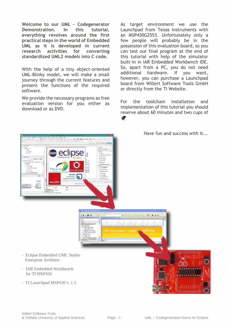
- Eclipse Embedded UML Studio
Enterprise Architect
- IAR Embedded Workbench
for TI MSP430
- TI Launchpad MSP430 v. 1.5
As target environment we use the Launchpad from Texas Instruments with an MSP430G2553. Unfortunately only a few people will probably be in the possession of this evaluation board, so you can test our final program at the end of this tutorial with help of the simulator built-in in IAR Embedded Workbench IDE. So, apart from a PC, you do not need additional hardware. If you want, however, you can purchase a Launchpad board from Willert Software Tools GmbH or directly from the TI Website.
For the toolchain installation and implementation of this tutorial you should reserve about 60 minutes and two cups of
Have fun and success with it...

Software & Installation
Willert Software Tools & Ostfalia University of Applied Sciences Page - 2 - UML – Codegeneration Demo for Eclipse
We start with the installation of our toolchain. All software you need is located on our Demo-DVD. In addition to the necessary tools you will also find an installation guide that will guide you quickly through the installation process. Therefore we will not describe the installation process in detail in this tutorial. We rather briefly discuss the possibilities of the individual tools.
In addition, you can download this free Demo-DVD the websites of the Ostfalia University of Applied Sciences: www.ostfalia.de/cms/de/ivs/ease/Merapi/
Tool description
For this demonstration, we build a bridge to the well-known Eclipse technology. To start instantly and don’t bother you with configuring eclipse in the right way, we build the Eclipse Embedded UML Studio.
This product is a bundle of different eclipse based tools.
Papyrus UML
Papyrus is a graphical editing tool for UML2 as defined by OMG. Papyrus targets to implement 100% of the OMG specification! It is written to be integrated seamlessly into the eclipse environment and provide powerful diagrams for creating UML models.
WST ModelXChanger
The ModelXChanger is co-working product from Willert Software Tools and the Ostfalia University of Applied Sciences which is aimed to convert models into different formats. In this case, the UML model will be converted into C-Code, so the ModelXChanger acts as code generator for C. The ModelXChanger is integrated into the Eclipse Embedded UML Studio but is also available as standalone application.
IAR Embedded Workbench
We need the IAR Embedded Workbench IDE to build and flash our executable model to the target or to let it run in the built-in simulator. On top of that the IDE offers additional debugging possibilities for our model. The code limitation of the evaluation version is 4 kByte.
TI Launchpad If you want to use real hardware for your application we suggest the Launchpad (version 1.5 or higher) from Texas Instruments. This board supports the MSP430G product family. But not every target device of the MSP430G product family is suitable for our RXF framework. Make sure that the used target device has at least 8 kByte of ROM and 512 kByte of RAM. We suggest the MSP430G2553.
In order to check for correct assembly, make sure that your board looks like in the picture:
Make sure that the controller is placed correctly on the socket with the nose at top to avoid a short circuit.
System Requirements (minimum)
Win XP (SP1/SP2/SP3) / Win 7
1 GB free disk space / 512MB RAM

IAR Embedded Workbench – Prepare Project
Willert Software Tools & Ostfalia University of Applied Sciences Page - 3 - UML – Codegeneration Demo for Eclipse
Prepare the project
Before we start with modeling, we will first do some preparation.
Run the IAR Embedded Workbench.
Then create a new project using Project Create New Project…
In the Create New Project wizard select Empty Project and ensure, that the toolchain is set to MSP430.
In the next dialog choose a folder in which you want to save the project. You are free in how to name the project and where to store it, but remember the location, you will need it later.
We give you some space here for notes to the location you choosed.
Now, your new created project should appear in your workspace, on the left side.
We have to adjust some settings of the project. Select the project root node and open the options of the project.
In General Options change the Device to MSP430G2553.
As default, the project uses the Simulator as target environment. Because we want to see a LED flashing on your MSP430 board, we have to change this setting.
Navigate to the Debugger options and set the driver to FET Debugger.
Confirm the dialog with OK.
This should be enough at the moment. We will return back here after we modeled our system during the next steps.
Embedded UML Studio – Overview
Willert Software Tools & Ostfalia University of Applied Sciences Page - 4 - UML – Codegeneration Demo for Eclipse
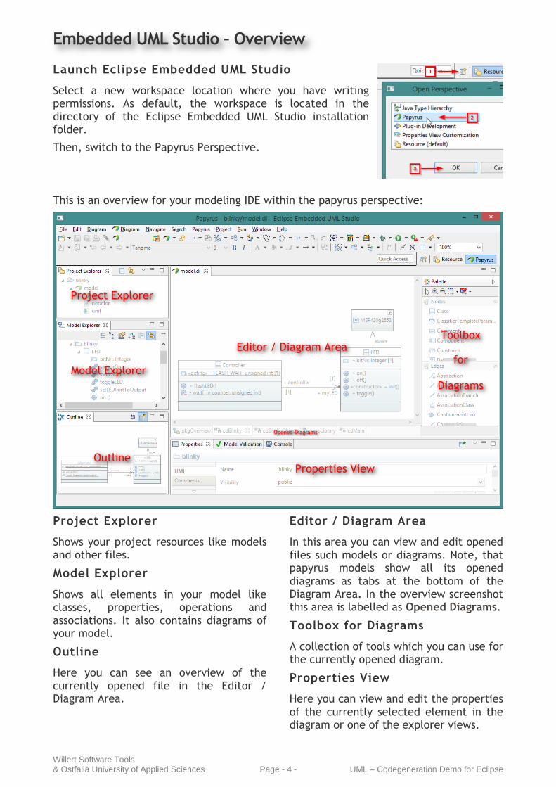
Launch Eclipse Embedded UML Studio
Select a new workspace location where you have writing permissions. As default, the workspace is located in the directory of the Eclipse Embedded UML Studio installation folder.
Then, switch to the Papyrus Perspective.
This is an overview for your modeling IDE within the papyrus perspective:
Project Explorer
Shows your project resources like models and other files.
Model Explorer
Shows all elements in your model like classes, properties, operations and associations. It also contains diagrams of your model.
Outline
Here you can see an overview of the currently opened file in the Editor / Diagram Area.
Editor / Diagram Area
In this area you can view and edit opened files such models or diagrams. Note, that papyrus models show all its opened diagrams as tabs at the bottom of the Diagram Area. In the overview screenshot this area is labelled as Opened Diagrams.
Toolbox for Diagrams
A collection of tools which you can use for the currently opened diagram.
Properties View
Here you can view and edit the properties of the currently selected element in the diagram or one of the explorer views.
Project Explorer
Model Explorer
Editor / Diagram Area
Properties View
Opened Diagrams
Toolbox
for
Diagrams
Outline

Model blinky example in UML
Willert Software Tools & Ostfalia University of Applied Sciences Page - 5 - UML – Codegeneration Demo for Eclipse
Create new Papyrus Project
Then create a new Papyrus Project using the Project Wizard. Go through the wizard, set the project name to blinky and select EmbeddedC as Diagram Language.
Then click Finish to create the new project.
Create Package Diagram
Create a new Package Diagram in the Root of the model using the context menu on the EmbeddedCmodel and name it pkgOverview.
Create a new Package blinky.
In the Model Explorer, you can now see the recently created package.
Create Class LED
Use the context menu of the Package blinky to create a new Class Diagram and name the diagram cdBlinky.
Create a class and name it LED.
Now, we want to add some operations to the LED so we can switch it on and off.
Select in the Tool Palette and add the operations on() and off().
Because we need to know the pin or the bit number where the LED is connected,
select and add the Property bitNr to the LED.
Attention: The text editor of properties expects a special complex syntax and reports an error if you only type the name.
So we use the view instead. Then we define a data type for this property. The UML provides some standard data types and we want to use the Integer type here.
Your Class should now look like this.
Add Behavior
Now we want to add the behavior of the on() and off() operations.
Therefore first select the on() operation,
go to the view and at nearby Method press
the button to add a new method behavior.
In the next dialog on the right side add a new FunctionBehavior.

Model blinky example in UML
Willert Software Tools & Ostfalia University of Applied Sciences Page - 6 - UML – Codegeneration Demo for Eclipse
Now we need to select a container where the new function behavior should be stored in the UML model. We choose the class LED.
As Reference select ownedBehavior.
In the next dialog, name the new FunctionBehavior switchOn. Then add a new Language entry for C and enter the implementation
P1OUT |= (1 << me->bitNr);
Confirm the dialogs with OK until you are back to the class diagram.
Repeat the steps for the Method off to create a FunctionBehavior switchOff with the implementation
P1OUT &= ~(1 << me->bitNr);
Add constructor
The LED needs some initialization code that sets the µC connected port as output. Therefore, first create a further
init and add the FunctionBehavior setLEDPortToOutput.
P1DIR |= (1 << me->bitNr);
The UML doesn’t define a specific Operation type for constructors or destructors. So to give the init() operation this specific semantic, we use a stereotype to sign it as constructor.
Therefore select the init() operation, go to
the tab Profile and apply the stereotype Constructor.
Because we simply want to toggle the LED,
we want to provide a further toggle(). Also add a FunctionBehavior toggleLED:
P1OUT ^= (1 << me->bitNr);
The following table shows an overview of all the FunctionBehavior implementations of the class LED.
P1OUT |= (1 << me->bitNr);
P1OUT &= ~(1 << me->bitNr);
P1OUT ^= (1 << me->bitNr);
P1DIR |= (1 << me->bitNr);
Model blinky example in UML
Willert Software Tools & Ostfalia University of Applied Sciences Page - 7 - UML – Codegeneration Demo for Eclipse
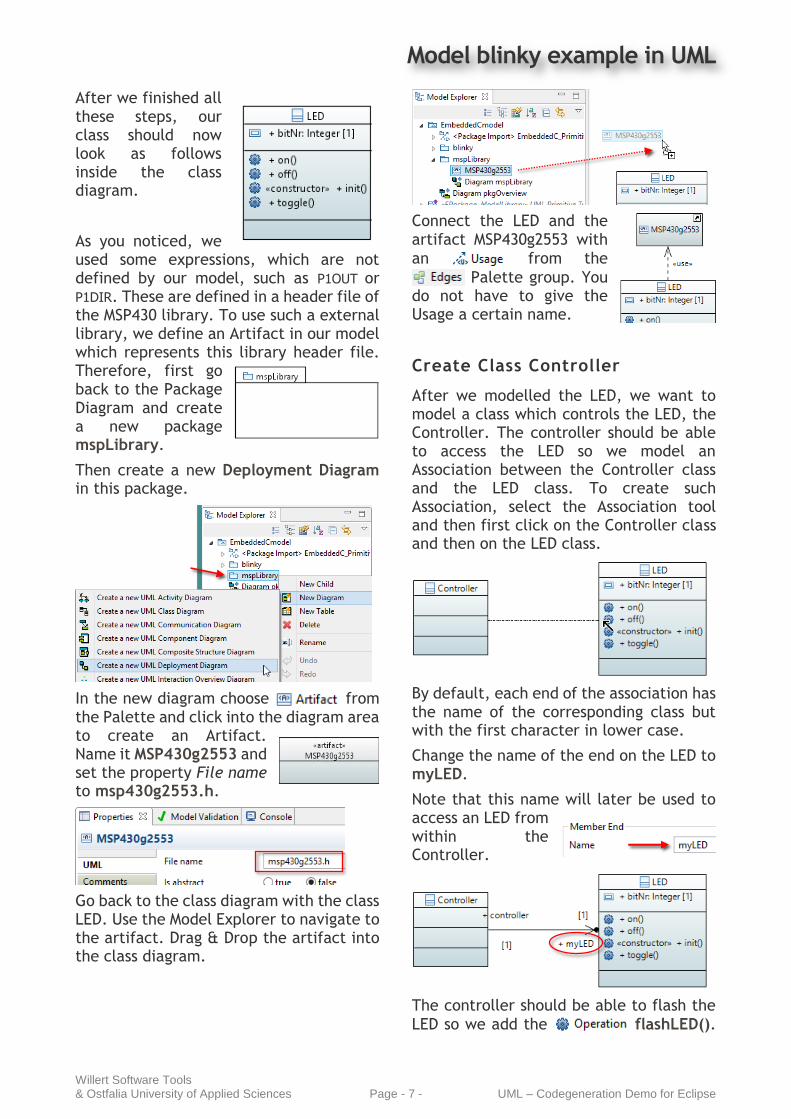
After we finished all these steps, our class should now look as follows inside the class diagram.
As you noticed, we used some expressions, which are not defined by our model, such as P1OUT or P1DIR. These are defined in a header file of the MSP430 library. To use such a external library, we define an Artifact in our model which represents this library header file. Therefore, first go back to the Package Diagram and create a new package mspLibrary.
Then create a new Deployment Diagram in this package.
In the new diagram choose from the Palette and click into the diagram area to create an Artifact. Name it MSP430g2553 and set the property File name to msp430g2553.h.
Go back to the class diagram with the class LED. Use the Model Explorer to navigate to the artifact. Drag & Drop the artifact into the class diagram.
Connect the LED and the artifact MSP430g2553 with
an from the
Palette group. You do not have to give the Usage a certain name.
Create Class Controller
After we modelled the LED, we want to model a class which controls the LED, the Controller. The controller should be able to access the LED so we model an Association between the Controller class and the LED class. To create such Association, select the Association tool and then first click on the Controller class and then on the LED class.
By default, each end of the association has the name of the corresponding class but with the first character in lower case.
Change the name of the end on the LED to myLED.
Note that this name will later be used to access an LED from within the Controller.
The controller should be able to flash the
LED so we add the flashLED().
Model blinky example in UML
Willert Software Tools & Ostfalia University of Applied Sciences Page - 8 - UML – Codegeneration Demo for Eclipse
We want the Controller to wait a certain time between toggling the LED so we also
create a new wait().
Before we create the FunctionBehavior for flashing the LED, we first focus on the wait(). Let us modify some settings of the
Operation inside the view. First, we set the Visibility to private, because we only want to use this operation inside the class Controller. Then we set it as static, because the Operation doesn’t depend on any state of Controller Objects which means, it does not access any properties or relations to other objects.
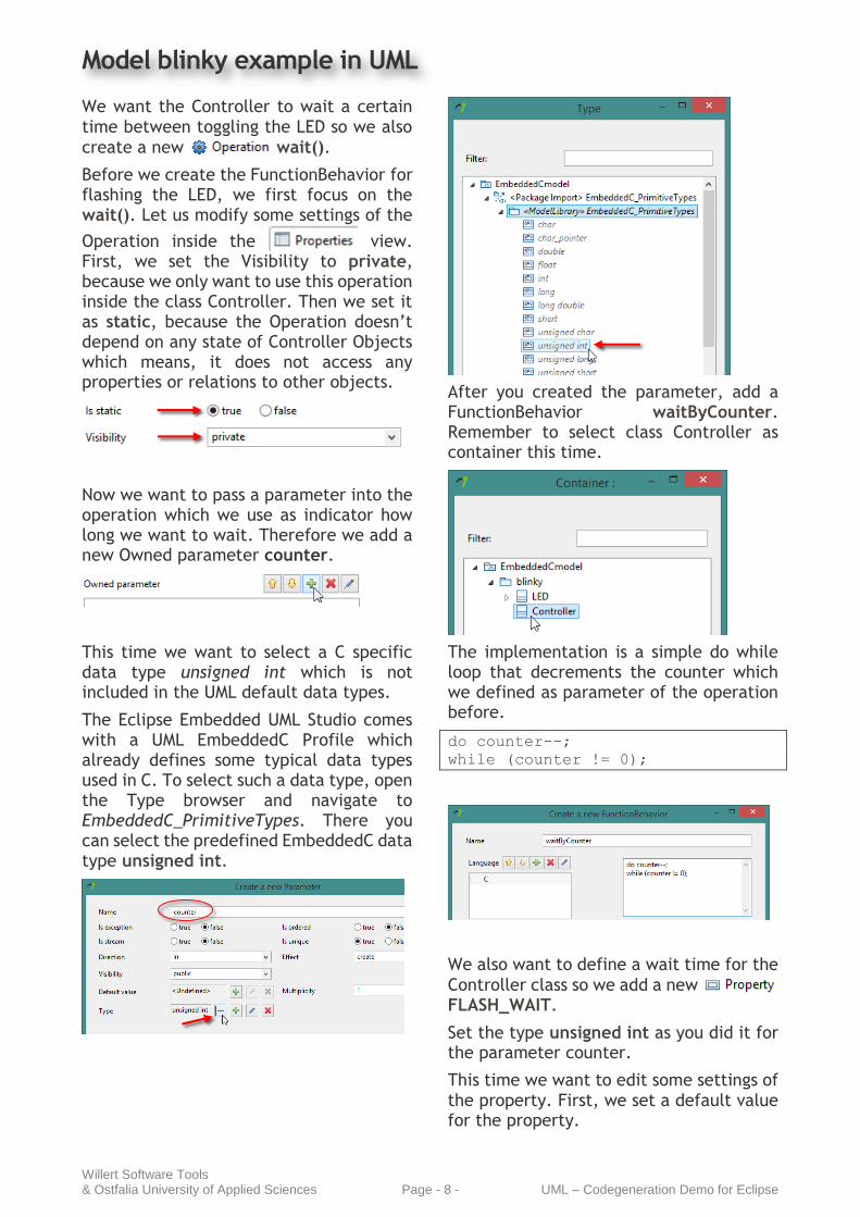
Now we want to pass a parameter into the operation which we use as indicator how long we want to wait. Therefore we add a new Owned parameter counter.
This time we want to select a C specific data type unsigned int which is not included in the UML default data types.
The Eclipse Embedded UML Studio comes with a UML EmbeddedC Profile which already defines some typical data types used in C. To select such a data type, open the Type browser and navigate to EmbeddedC_PrimitiveTypes. There you can select the predefined EmbeddedC data type unsigned int.
After you created the parameter, add a FunctionBehavior waitByCounter. Remember to select class Controller as container this time.
The implementation is a simple do while loop that decrements the counter which we defined as parameter of the operation before.
do counter--;
while (counter != 0);
We also want to define a wait time for the
Controller class so we add a new FLASH_WAIT.
Set the type unsigned int as you did it for the parameter counter.
This time we want to edit some settings of the property. First, we set a default value for the property.

Model blinky example in UML
Willert Software Tools & Ostfalia University of Applied Sciences Page - 9 - UML – Codegeneration Demo for Eclipse
Click on the next to the field for a Default value and select LiteralInteger. Enter 50000 as value.
You may leave the name empty.
Once you created the LiteralInteger you can change the value at any time using the
button.
Back to the view, set the Visibility to private, because we only want to use it inside the Controller. Then set the property as static and read only, because we do not want to change it during runtime.
It is possible to generate those properties
as a #define. Therefore we select the Property and apply the stereotype «Define».
Ok, now it’s time add a FunctionBehavior to the operation flashLED(). It doesn’t matter to give it the same name as the Operation so name it flashLED. The icons the operation and the FunctionBehaviors will later show you the kind of type they are.
FunctionBehavior Operation
This is the first time we want to call operations which we modeled before so
you need some background knowledge about the generated code.
In general, an operation is generated with the following syntax:
<Class>_<Operation>(<me>, <Parameters>)
<Class> The name of the Class
<Operation> The name of the Operation
<me> A pointer to the struct instance of the target class
<Parameters> The operation parameters
If the operation is static, the generated function has no me-pointer.
Back to the implementation of the flashLED FunctionBehavior, this means, we can toggle the LED using the following code lines.
for (;;)
{
LED_toggle(me->myLED);
Controller_wait(FLASH_WAIT);
}
We do not want to stop this behavior so it is ok to don’t have a break condition for this loop at the moment.
The previous steps should result in a class diagram looking like that:
Create Instances
After finishing the class diagram we want to create instances or objects of our classes. Papyrus do not provide an Object Diagram so we use a second class diagram to model our Objects.
In the UML, an object is represented as an Instance Specification. Its classifier is the instantiated class.

Model blinky example in UML
Willert Software Tools & Ostfalia University of Applied Sciences Page - 10 - UML – Codegeneration Demo for Eclipse
Connections between objects are called links. In the UML a link is also represented as an InstanceSpecification. In this case, the instantiated classifier is the association between the classes.
In the Model Explorer, navigate to the package blinky and there create a new Class Diagram.
Name the diagram cdBlinkyObjects.
To create an Object for the LED, choose in the Palette, click
into the diagram and thus create an Instance Specification with the name led. Furthermore, we need to define the Class of the represented instance. In the
view, add the LED class to the
Classifiers by using the button and then select (double click) the class LED from the model on the left side.
Create an Instance Specification for the controller by the same way so your Class/Object Diagram looks as follows.
We still need to connect the instances by
using an which can
be found in the group. Then first click on the controller instance and then on the led instance. A dialog will appear
which ask you to select the association for the link.
After that, your diagram should look like follows.
Please note that the Papyrus diagrams have a problem with representing the labels for the ends of the Instance Specification link. This might cause the diagram to display the labels only with <UNSPECIFIED>. You can either close and reopen the diagram or ignore this issue.

Convert UML model to C code
Willert Software Tools & Ostfalia University of Applied Sciences Page - 11 - UML – Codegeneration Demo for Eclipse
Export the UML model to C code
Congratulation for finishing the main modeling part.
Now we can have a first look at the code that will be generated by our UML model.
Therefore, the Eclipse Embedded UML Studio includes an Eclipse feature which integrates the Willert ModelXChanger into the Eclipse environment. The plugin is registered for files with .uml extension and can be reached via the context menu of either an UML file (.uml) or any Papyrus diagram content.
In the context menu you will find the entry
which contains
submenu entries for the ModelXChanger features.
1 Opens the Options Dialog
2 Opens the Licence Dialog
3 Generate C-Code from UML
4 Update Model with changes in C-Code (not available yet)
We choose the entry . If this is the first time, we want to generate code for this model, an Options dialog appears which asks for the target folder. Remember the location of the workspace of your IAR Embedded Workbench project
and for this location. Ensure that the option Copy additional files is enabled. Confirm the dialog with OK. The ModelXChanger export mechanism now generates code from the UML model.
You can change these settings at any time using the Options dialog for the exported file.
Let’s go back to the IAR Embedded Workbench project which we created during the first steps of this Getting Started.
The project is still empty. We need to add the generated files to the project manually. Projects in IAR Embedded Workbench don’t have a folder hierarchy, but you can add groups. For a better overview, it is recommended to use groups like the folders in your file system. Because packages of the UML model are generated as folders, we now add a group blinky to the IAR Embedded Workbench project.
Then select the group, open the context menu and navigate to Add Files…
You should already be located in your project directory. If not, browse there. Then go into the folder blinky and select all files and press Open.
1
2
3
4
Convert UML model to C code
Willert Software Tools & Ostfalia University of Applied Sciences Page - 12 - UML – Codegeneration Demo for Eclipse
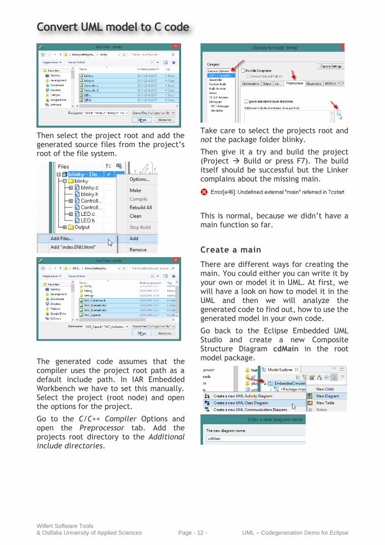
Then select the project root and add the generated source files from the project’s root of the file system.
The generated code assumes that the compiler uses the project root path as a default include path. In IAR Embedded Workbench we have to set this manually. Select the project (root node) and open the options for the project.
Go to the C/C++ Compiler Options and open the Preprocessor tab. Add the projects root directory to the Additional include directories.
Take care to select the projects root and not the package folder blinky.
Then give it a try and build the project (Project Build or press F7). The build itself should be successful but the Linker complains about the missing main.
This is normal, because we didn’t have a main function so far.
Create a main
There are different ways for creating the main. You could either you can write it by your own or model it in UML. At first, we will have a look on how to model it in the UML and then we will analyze the generated code to find out, how to use the generated model in your own code.
Go back to the Eclipse Embedded UML Studio and create a new Composite Structure Diagram cdMain in the root model package.

Convert UML model to C code
Willert Software Tools & Ostfalia University of Applied Sciences Page - 13 - UML – Codegeneration Demo for Eclipse
Then create a class Main in the new diagram and create the operation main() inside the Main class. Make the main static, because we don’t want to have the me pointer as parameter in the generated code. If you remember on how functions will be generated, you will see, that currently our generated function name will
be Main_main(). To avoid the leading class name, you can apply the stereotype «StrictName» to the operation.
Add a FunctionBehavior mainBehavior for the main operation and enter the following C-Code implementation.
WDTCTL = WDTPW + WDTHOLD;
blinkyPkg_Init();
Controller* controller =
blinkyPkg_getController();
Controller_flashLED(controller);
The first line stops the watchdog of the MSP430 so the endless loop will not be terminated.
The second line initializes the package blinky. This causes the initialization of all instances inside this package. In our case this are the objects controller and led. Each package provides a function for initialization. Here we want to call the package init for the blinky package.
The next two lines are responsible to run the flashLED() of the controller. To get the controller instance from the blinky package, the package provides a getter for each instance in it. Such we get the instance of the controller and call the function flashLED().
As you see, we have some dependencies to other elements, which are not defined inside the Main class. To turn off the watchdog we need the Artifact MSP430g2553 again. To use the instance controller, we also need a Usage to this instance.
In the Model Explorer, navigate to the InstanceSpecification controller and drag & drop it into the Main class diagram.
Repeat that step with the Class Controller and the Artifact MSP430g2553 and drag & drop them into the class diagram, too.
Connect the Main to the Instance Specification, to the class and to the
artifact using the from the Palette group.
Your Main class diagram should now look like this.
Save the model and generate the code again.
Then open the IDE Embedded Workbench project. We still have to add the generated source into the project. Select the project root and choose Add Files… from its context menu.

Convert UML model to C code
Willert Software Tools & Ostfalia University of Applied Sciences Page - 14 - UML – Codegeneration Demo for Eclipse
Add the Main.c and Main.h and add it to the project.
Now all things are done to do a successful build. Give it a try and press F7 or use Project Make.
If everything is assembled correctly you can connect the board via USB to the host. No additional programming hard-ware is needed. All you need to do is to flash the device or enter the simulator (if no hardware available).
If you connect the launchpad for the first time, you will be asked to install the driver for the board. Just follow the instructions on the screen and the driver will be installed automatically. You don‘t need any additional driver software.
Now, it is time to enter the debug mode
with the download and debug button in the toolbar.
The application can be controlled by using the toolbar to run/stop the application and to step through the application on C level.
In order to debug on C-level, you can use breakpoints and it is possible to step through the application.
Embed generated code in your own program
If you open the source file main.c, you can see, what is needed to use the code which was generated from our model (Controller and LED).
There are includes to all classes we want to access.
#include “blinky/Controller.h”
Note, that the package structure is mapped to a foder structure, so also add the appropriate path.
If you want to access objects which was modelled by Instance Specifications, then you also have to include the package header. This file is generated with the same name as the package name.
#include “blinky/blinky.h”
For each object, the package code provides a getter function with the following syntax:
<Package>Pkg_get<Object>();
<Package> The name of the Package
<Object> The name of the Object with the first character as upper case.
These functions return a pointer value to the instantiated struct which represents the class.
Feel free to study the generated code also for the other classes. You will see how the code generator works and how to embed the modelling technology in your own projects.
Troubleshooting
If you have problems when generating
code you can have a look in the view to see the output of the UML2C-Plugin.

Notes

Notes


Editor:
Willert Software Tools GmbH
Hannoversche Straße 21 31675 Bückeburg
Tel.: +49 5722 - 9678 60
www.willert.de [email protected]
www.ostfalia.de [email protected]
Authors: Arne Noyer Joachim Engelhardt Alexander Tanke Lars Donner