uml modeling of network topologies for distributed computer system
TRANSCRIPT
Journal of Computing and Information Technology - CIT 17, 2009, 4, 327–334doi:10.2498/cit.1001319
327
UML Modeling of NetworkTopologies for DistributedComputer System
Vipin Saxena and Deepak AroraDepartment of Computer Science, Babasaheb Bhimrao Ambedkar University (A Central University), Lucknow, India
Nowadays, distributed computer systems have becomevery popular approach of computing as it delivers highend performance at a low cost. In a distributed computingenvironment, autonomous computers are connected bymeans of a communication network, arranged in a geo-metrical shape called network topology. In the presentpaper a detailed study of network topologies is donefor the distributed computer systems. A most popularUnified Modeling Language (UML) is used for modelingthe different network topologies. A comparative studyis done for 2D Mesh, Torus, and Hypercube networktopologies and their performance is also evaluated af-ter designing the UML Class, Sequence, and Activitydiagrams for the same.
Keywords: network topology, class diagram, sequencediagram, activity diagram
1. Introduction
Distributed computing systems have becomethe essential aspect of growing information tech-nology. The performance of any distributed sys-tem is certainly influenced by the technology,which we adopt in making network intercon-nections. Various researchers have done a lot ofwork on UML modeling, but limited researchpapers are available on UML modeling relatedto the distributed computer systems.
UML developed by Booch et al. [1] has proveditself as the most suitable visual presentationplatform for modeling the real world problems.Conallen [2] has defined the extensions in UMLfor modeling the designing issues related to anyweb application architecture. Coulouris, G. etal. [3], has explored the major challenges re-garding distributed systems through architec-
tural and fundamental models; various tech-nologies and case studies on Ethernet, wirelessLAN and ATM are also discussed. Huang andBode [4] compared the performance of ring andtree based network topologies for the distributedsystems and also suggested a distributed man-agement system for handling the failure. Issuesrelated to the implementation of distributed sys-tems are well explained by Milenkovic, M. [5].OMG [6, 7] elaborate the latest UML specifi-cations related to all real world problems, theirmodeling aspects and also the way of presen-tation for XML metadata specification in UMLdiagrams along with standard storage represen-tations. Pllana and Fahringer [8] have sug-gested the way how one can do the UML mod-eling for high performance applications, whichis an important reference in this regard. Fur-ther one more important reference by Pllanaand Fahringer [9], describes the UML modelingof design issues related to the parallel and dis-tributed applications. Another object-orienteddistributed architecture system is recently de-fined by Saxena V. et al. [10] through UMLmodeling, with a case study of a multiplex sys-tem.
In the present paper, three important networktopologies namely 2D Mesh, Torus and Hyper-cube are compared, which are commonly usedfor the concurrent processes execution in a dis-tributed environment. In the paper, UML mod-eling is done for these three network topologiesand the sequence diagram for process execu-tion under distributed environment is also rep-resented. The performance comparison is alsostudied by taking the variations in nodes for 2DMesh, Torus and Hypercube topologies.

328 UML Modeling of Network Topologies for Distributed Computer System
2. Background
2.1. Distributed Computer System
A distributed computer system consists of au-tonomous computers, connected via network.The computers involved in the distributed sys-tem can share both the localized as well as re-mote resources. However, it is quite expen-sive to access any remote resources in terms ofCPU overhead and communication cost. Nowa-days, a trend to develop distributed system isincreasingly moving ahead due to its featureslike high performance computing, scalability,security and reliability.
Figure 1. Distributed computer system.
Nowadays computation labs are adopting theconcept of distributed computer systems, whichis shown below in Figure 1. This figure showsthe connection of ‘N’ autonomous clients to dif-ferent servers connected through a communica-tion network. This network can be based uponany kind of network topology as required, interms of complexity, reliability and security.
2.2. Process Definition
Let us explain the definition of a process, whichis the basic entity of execution in any distributedcomputing environment. The process is ex-plained as a macro, subprogram, subroutine orblock of code etc., which has an identificationnumber called as process id. A processing unitis defined as a Process Execution Controller(PEC), which accepts process id through thread-ing and executes the corresponding process after
getting the required resources. The UML classdiagram of process consists of a number of at-tributes, as shown in Figure 2(a). The instanceof the process and multiple instances throughthe objects are also represented in Figure 2(b)and 2(c), respectively. This completes the pro-cess representation in a distributed environment.In the paper, each process is controlled by theseparate threads, which is going to be executedunder distributed environment. The parallel re-gion is defined as a buffer, which is handled bythe multiple threads, associated to the differentprocesses. A stereotype parallel region UMLclass diagram is shown in Figure 2(d) and asso-ciated activities representation is given in Figure2(e). In this figure the sub activities can be ex-ecuted many times in concurrent fashion by theuse of buffer, called code region.
Figure 2a. UML class diagram of process.
Figure 2b. Instance of process.
Figure 2c. Multiple instance of process.

UML Modeling of Network Topologies for Distributed Computer System 329
Figure 2d. UML class diagram of stereotype parallelregion.
Figure 2e. Sample activity diagram.
2.3. Topology
The processes which are going to be executed,handled by the multiple threads, can use the par-allel region in a concurrent manner. For the ex-ecution and communication purpose, these pro-cesses need to be arranged in a network topol-ogy. By the use of topology, the process canaccess the code region as per the availability ofthe resources, for faster execution.
In the present approach, different kinds of topolo-gies are selected, which are widely used insetting the labs for distributed computations.Through these topologies, which are executedin concurrent fashion, one can save a lot of pro-cess execution time. The UML class diagramsfor these three kinds of topologies are given inFigure 3(a), 3(b), and 3(c) for 2D Mesh, Torus,and Hypercube topology respectively. For theexecution of process having unique process id,the resources can be granted by the individualcomputer system or can be taken from differ-ent clients as per the availability of the network,which consists of autonomous computer sys-tems arranged in the distributed computing en-vironment.
Figure 3a. UML class diagram of 2d mesh topology.
Figure 3b. UML class diagram of torus topology.
Figure 3c. UML class diagram of hypercube topology.
2.4. Communication Lines
The communication among the processes canbe handled by the synchronization technique ifthe common resources are available at the clientcomputer system. The communication can be oftwo types; one approach is point-to-point proto-col method and another technique is broadcastprotocol method. The communication lines canbe connected as per the network demand andits topological specifications. UML class dia-grams for broadcast and P2P signal are given in
330 UML Modeling of Network Topologies for Distributed Computer System
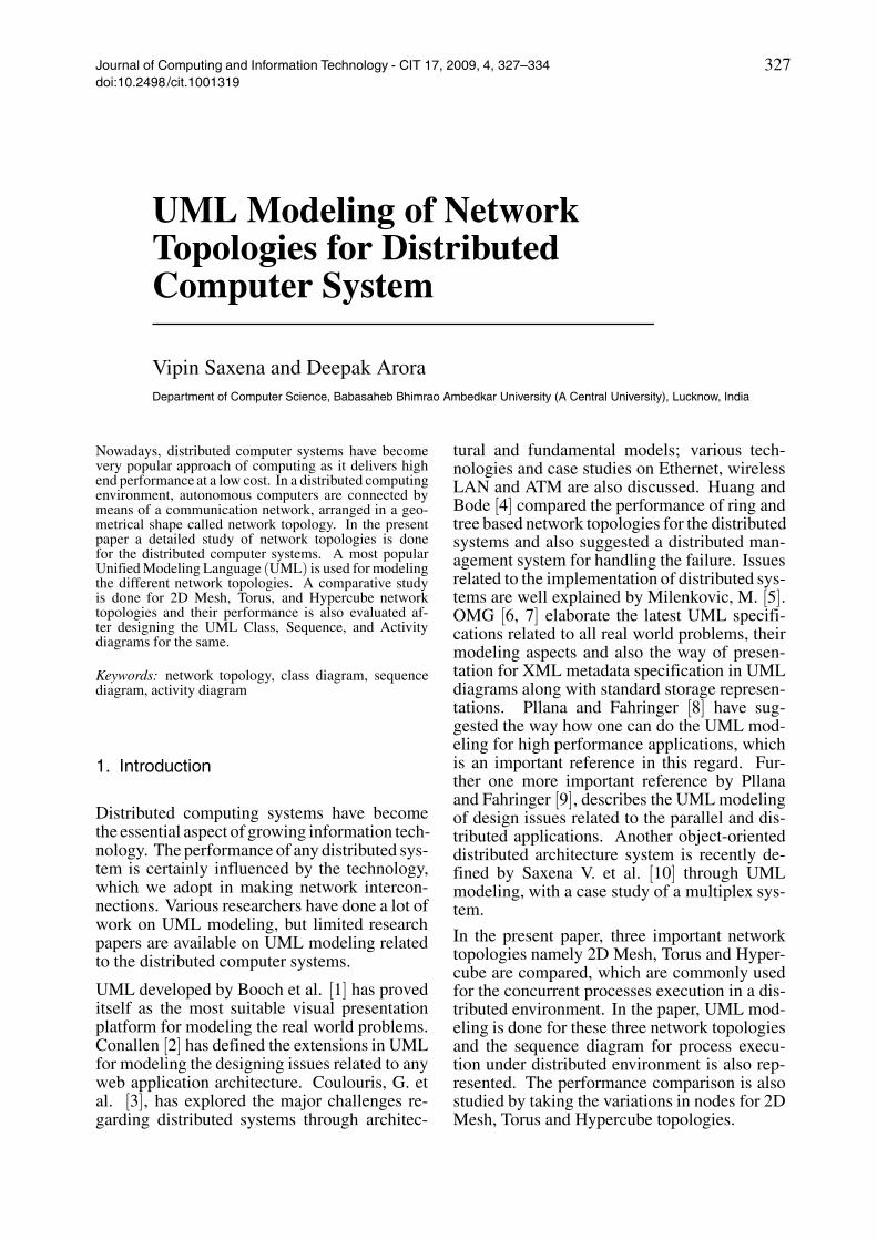
Figures 4(a) and 4(b). Signal event for processcommunication via broadcast and P2P approachare given in Figures 4(c) and 4(d) respectively.
Figure 4a. UML class diagram of broadcast signal.
Figure 4b. UML class diagram of P2P signal.
Figure 4c. Signal event for process communication viabroadcast approach.
Figure 4d. Signal event for process communication viaP2P approach.
3. UML Class Diagram for DistributedComputer System
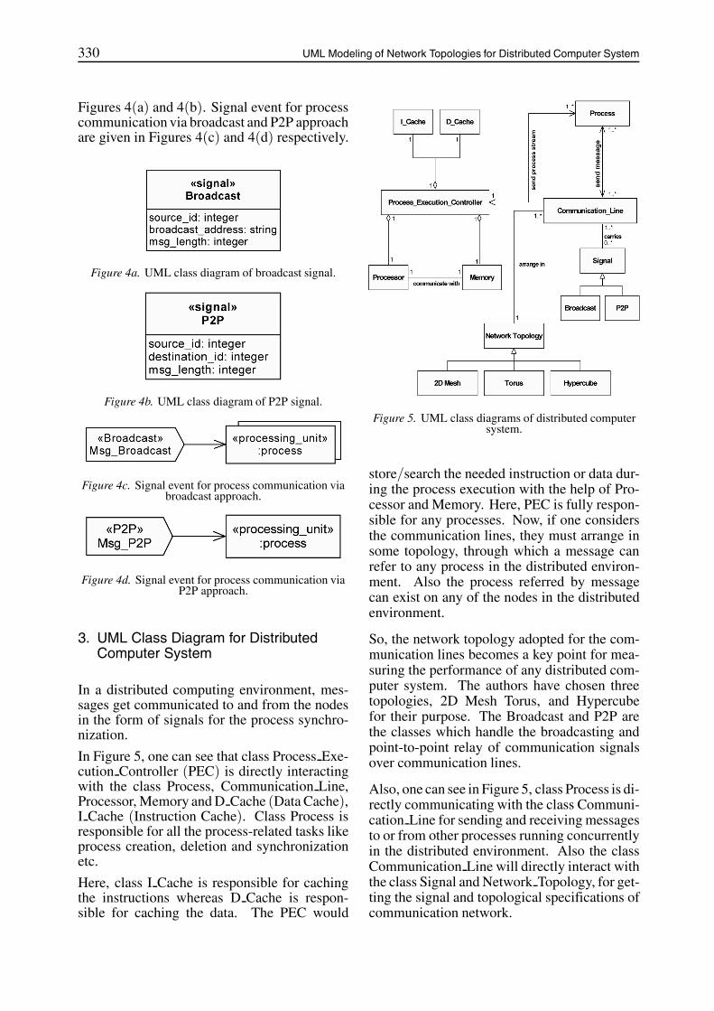
In a distributed computing environment, mes-sages get communicated to and from the nodesin the form of signals for the process synchro-nization.
In Figure 5, one can see that class Process Exe-cution Controller (PEC) is directly interactingwith the class Process, Communication Line,Processor, Memory and D Cache (Data Cache),I Cache (Instruction Cache). Class Process isresponsible for all the process-related tasks likeprocess creation, deletion and synchronizationetc.
Here, class I Cache is responsible for cachingthe instructions whereas D Cache is respon-sible for caching the data. The PEC would
Figure 5. UML class diagrams of distributed computersystem.
store/search the needed instruction or data dur-ing the process execution with the help of Pro-cessor and Memory. Here, PEC is fully respon-sible for any processes. Now, if one considersthe communication lines, they must arrange insome topology, through which a message canrefer to any process in the distributed environ-ment. Also the process referred by messagecan exist on any of the nodes in the distributedenvironment.
So, the network topology adopted for the com-munication lines becomes a key point for mea-suring the performance of any distributed com-puter system. The authors have chosen threetopologies, 2D Mesh Torus, and Hypercubefor their purpose. The Broadcast and P2P arethe classes which handle the broadcasting andpoint-to-point relay of communication signalsover communication lines.
Also, one can see in Figure 5, class Process is di-rectly communicating with the class Communi-cation Line for sending and receiving messagesto or from other processes running concurrentlyin the distributed environment. Also the classCommunication Line will directly interact withthe class Signal and Network Topology, for get-ting the signal and topological specifications ofcommunication network.
UML Modeling of Network Topologies for Distributed Computer System 331
4. UML Activity Diagram for DistributedComputer System
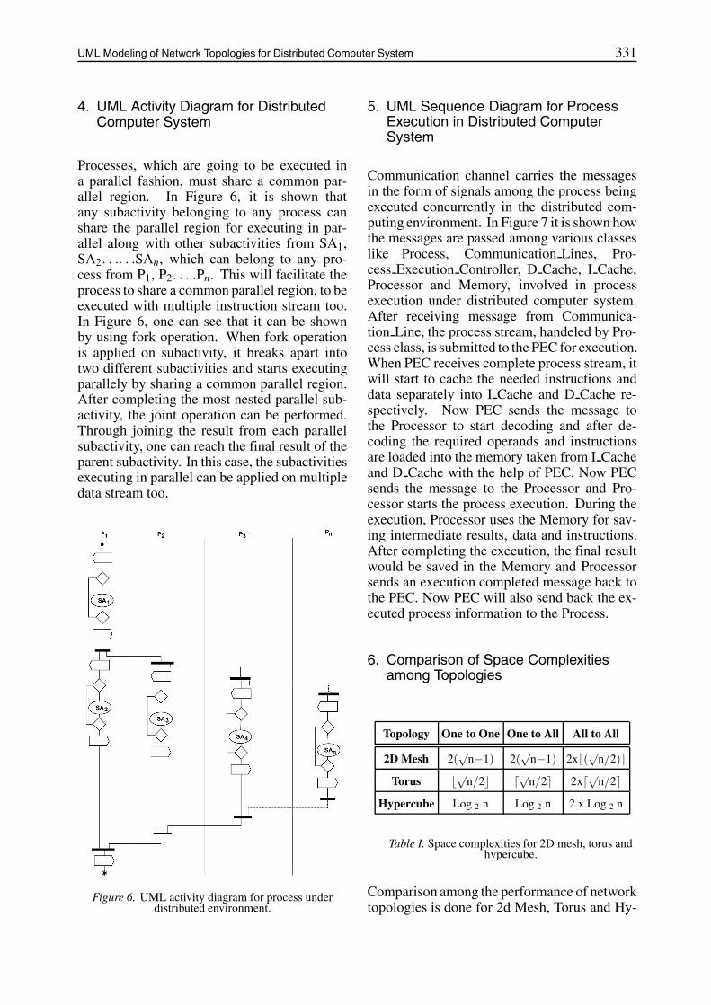
Processes, which are going to be executed ina parallel fashion, must share a common par-allel region. In Figure 6, it is shown thatany subactivity belonging to any process canshare the parallel region for executing in par-allel along with other subactivities from SA1,SA2. . .. . .SAn, which can belong to any pro-cess from P1, P2. . ...Pn. This will facilitate theprocess to share a common parallel region, to beexecuted with multiple instruction stream too.In Figure 6, one can see that it can be shownby using fork operation. When fork operationis applied on subactivity, it breaks apart intotwo different subactivities and starts executingparallely by sharing a common parallel region.After completing the most nested parallel sub-activity, the joint operation can be performed.Through joining the result from each parallelsubactivity, one can reach the final result of theparent subactivity. In this case, the subactivitiesexecuting in parallel can be applied on multipledata stream too.
Figure 6. UML activity diagram for process underdistributed environment.
5. UML Sequence Diagram for ProcessExecution in Distributed ComputerSystem
Communication channel carries the messagesin the form of signals among the process beingexecuted concurrently in the distributed com-puting environment. In Figure 7 it is shown howthe messages are passed among various classeslike Process, Communication Lines, Pro-cess Execution Controller, D Cache, I Cache,Processor and Memory, involved in processexecution under distributed computer system.After receiving message from Communica-tion Line, the process stream, handeled by Pro-cess class, is submitted to the PEC for execution.When PEC receives complete process stream, itwill start to cache the needed instructions anddata separately into I Cache and D Cache re-spectively. Now PEC sends the message tothe Processor to start decoding and after de-coding the required operands and instructionsare loaded into the memory taken from I Cacheand D Cache with the help of PEC. Now PECsends the message to the Processor and Pro-cessor starts the process execution. During theexecution, Processor uses the Memory for sav-ing intermediate results, data and instructions.After completing the execution, the final resultwould be saved in the Memory and Processorsends an execution completed message back tothe PEC. Now PEC will also send back the ex-ecuted process information to the Process.
6. Comparison of Space Complexitiesamong Topologies
Topology One to One One to All All to All
2D Mesh 2(√
n−1) 2(√
n−1) 2x�(√n/2)�Torus �√n/2� �√n/2� 2x�√n/2�
Hypercube Log 2 n Log 2 n 2 x Log 2 n
Table I. Space complexities for 2D mesh, torus andhypercube.
Comparison among the performance of networktopologies is done for 2d Mesh, Torus and Hy-

332 UML Modeling of Network Topologies for Distributed Computer System
Figure 7. UML sequence diagram for process execution under distributed computer environment.
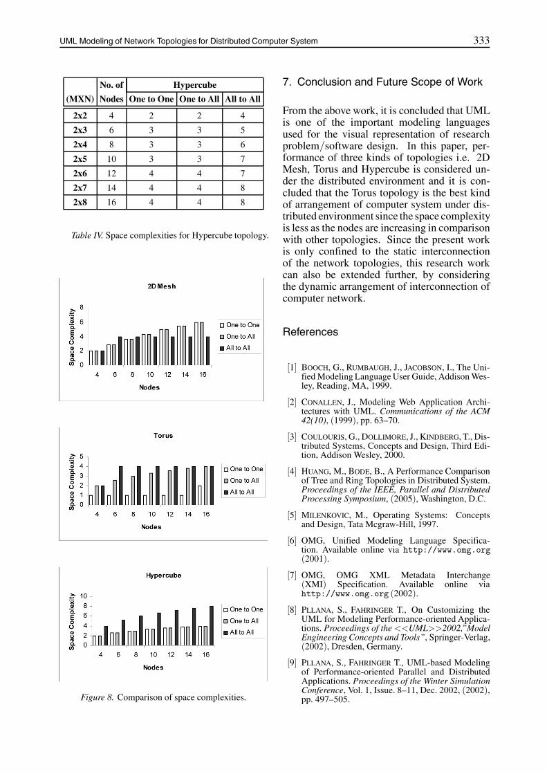
percube technologies. The communication isconsidered as one to one, one to all and all toall. Table I gives the measurements of spacecomplexities for 2DMesh,Torus andHypercubetechnologies. On the basis of this table, TableII, III and IV are designed, which shows thecomparison of space complexities as number ofnodes in the network system under distributedenvironment is increasing. As nodes are in-creasing, the performance of Torus topologycomes best over the 2D Mesh and Hypercubenetwork technologies since the space complex-ity is low in case of Torus topology for one toone communication. In case of one to all com-munication system, behaviour of Torus and Hy-percube is the same whereas, in case of one toall, performance of 2D Mesh and Torus topolo-gies is the same. This is also depicted in Figure8, in which it is studied that, in general, perfor-mance of Torus topology is better in comparisonwith 2D Mesh and Hypercube technologies.
No. of 2D Mesh(MXN) Nodes One to One One to All All to All
2x2 4 2 2 2
2x3 6 3 3 4
2x4 8 4 4 4
2x5 10 4 4 4
2x6 12 5 5 4
2x7 14 5 5 4
2x8 16 6 6 4
Table II. Space complexities for 2D Mesh topology.
No. of Torus(MXN) Nodes One to One One to All All to All
2x2 4 1 2 2
2x3 6 1 3 4
2x4 8 1 3 4
2x5 10 1 3 4
2x6 12 1 4 4
2x7 14 1 4 4
2x8 16 2 4 4
Table III. Space complexities for Torus topology.
UML Modeling of Network Topologies for Distributed Computer System 333
No. of Hypercube
(MXN) Nodes One to One One to All All to All
2x2 4 2 2 4
2x3 6 3 3 5
2x4 8 3 3 6
2x5 10 3 3 7
2x6 12 4 4 7
2x7 14 4 4 8
2x8 16 4 4 8
Table IV. Space complexities for Hypercube topology.
Figure 8. Comparison of space complexities.
7. Conclusion and Future Scope of Work
From the above work, it is concluded that UMLis one of the important modeling languagesused for the visual representation of researchproblem/software design. In this paper, per-formance of three kinds of topologies i.e. 2DMesh, Torus and Hypercube is considered un-der the distributed environment and it is con-cluded that the Torus topology is the best kindof arrangement of computer system under dis-tributed environment since the space complexityis less as the nodes are increasing in comparisonwith other topologies. Since the present workis only confined to the static interconnectionof the network topologies, this research workcan also be extended further, by consideringthe dynamic arrangement of interconnection ofcomputer network.
References
[1] BOOCH, G., RUMBAUGH, J., JACOBSON, I., The Uni-fied Modeling Language User Guide, Addison Wes-ley, Reading, MA, 1999.
[2] CONALLEN, J., Modeling Web Application Archi-tectures with UML. Communications of the ACM42(10), (1999), pp. 63–70.
[3] COULOURIS, G., DOLLIMORE, J., KINDBERG, T., Dis-tributed Systems, Concepts and Design, Third Edi-tion, Addison Wesley, 2000.
[4] HUANG, M., BODE, B., A Performance Comparisonof Tree and Ring Topologies in Distributed System.Proceedings of the IEEE, Parallel and DistributedProcessing Symposium, (2005), Washington, D.C.
[5] MILENKOVIC, M., Operating Systems: Conceptsand Design, Tata Mcgraw-Hill, 1997.
[6] OMG, Unified Modeling Language Specifica-tion. Available online via http://www.omg.org(2001).
[7] OMG, OMG XML Metadata Interchange(XMI) Specification. Available online viahttp://www.omg.org (2002).
[8] PLLANA, S., FAHRINGER T., On Customizing theUML for Modeling Performance-oriented Applica-tions. Proceedings of the <<UML>>2002,”ModelEngineering Concepts and Tools”, Springer-Verlag,(2002), Dresden, Germany.
[9] PLLANA, S., FAHRINGER T., UML-based Modelingof Performance-oriented Parallel and DistributedApplications. Proceedings of the Winter SimulationConference, Vol. 1, Issue. 8–11, Dec. 2002, (2002),pp. 497–505.

334 UML Modeling of Network Topologies for Distributed Computer System
[10] SAXENA,V., ARORA, D., AHMAD S., Object-orientedDistributed Architecture System through UML. InProceedings of the IEEE International Conferenceon Advances in Computer Vision and InformationTechnology (2007), Aurangabad (MS), India.
Received: August, 2008Accepted: February, 2009
Contact addresses:
Dr. Vipin SaxenaDepartment of Computer Science
B.B. Ambedkar University (A Central University)Vidya Vihar Rae Bareilly Road
Lucknow U.P. 226025, Indiae-mail: [email protected]
Deepak AroraDepartment of Computer Science
B.B. Ambedkar University (A Central University)Vidya Vihar Rae Bareilly Road
Lucknow U.P. 226025, Indiae-mail: [email protected]
VIPIN SAXENA is a Reader, Dept. of Computer Science, BabasahebBhimrao Ambedkar University, Lucknow, India. He got his M.Phil.Degree in computer application in 1991 & Ph.D. Degree in scientificcomputing from the University of Roorkee (renamed as Indian Instituteof Technology, India) in 1997. He has more than 12 years teachingexperience and 16 years research experience in the field of scientificcomputing & software engineering. Currently he is proposing softwaredesigns by the use of Unified Modeling Language for various researchproblems related to the software domains & advanced computer ar-chitecture. He has published more than 55 international and nationalpublications.
DEEPAK ARORA is a Research Scholar, Dept. of Computer Science,Babasaheb Bhimrao Ambedkar University, Lucknow, India. He got hisMaster Degree in computer applications in 2003 and M. Phil. Degreein computer science in 2006. Currently he is actively engaged in theresearch work on distributed computing systems through the UnifiedModeling Language. Ha has produced several outstanding publicationson Distributed Computing Systems. Also, he is a member of ‘TheIndian Science Congress Association’, Kolkata, India and ‘ComputerSociety of India’, Mumbai, India.