uml notation guide - washington university in st. louis ...kjg/cse132/forms/uml notation...
TRANSCRIPT

UML Notation Guide
version 1.11 September 1997
Rational Software ■ Microsoft ■ Hewlett-Packard ■ Oracle
Sterling Software ■ MCI Systemhouse ■ Unisys ■ ICON Computing
IntelliCorp ■ i-Logix ■ IBM ■ ObjecTime ■ Platinum Technology ■ Ptech
Taskon ■ Reich Technologies ■ Softeam
ad/97-08-05

Copyright © 1997 Rational Software CorporationCopyright © 1997 Microsoft CorporationCopyright © 1997 Hewlett-Packard Company.Copyright © 1997 Oracle Corporation.Copyright © 1997 Sterling Software.Copyright © 1997 MCI Systemhouse Corporation.Copyright © 1997 Unisys Corporation.Copyright © 1997 ICON Computing.Copyright © 1997 IntelliCorp.Copyright © 1997 i-Logix.Copyright © 1997 IBM Corporation.Copyright © 1997 ObjecTime Limited.Copyright © 1997 Platinum Technology Inc.Copyright © 1997 Ptech Inc.Copyright © 1997 Taskon A/S.Copyright © 1997 Reich TechnologiesCopyright © 1997 Softeam
Photocopying, electronic distribution, or foreign-language translation of this document is permitted,provided this document is reproduced in its entirety and accompanied with this entire notice, including thefollowing statement:
The most recent updates on the Unified Modeling Language are available via the worldwide web: http://www.rational.com/uml
The UML logo is a trademark of Rational Software Corporation.

. . .
. . . 4
. .
. . . . 11
. . . 13
. . .
. .
. . . 3
. . . . 3
Contents
1. DOCUMENT OVERVIEW 1
2. DIAGRAM ELEMENTS 3
2.1 Graphs and their Contents . . . . . . . . . . . . . . . . . . . . . . . . . . . . . . . . . . . . . . . . . . . . . . . . 32.2 Drawing paths . . . . . . . . . . . . . . . . . . . . . . . . . . . . . . . . . . . . . . . . . . . . . . . . . . . . . . . . . . . . 42.3 Invisible Hyperlinks And The Role Of Tools . . . . . . . . . . . . . . . . . . . . . . . . . . . . . . . . . 2.4 Background information . . . . . . . . . . . . . . . . . . . . . . . . . . . . . . . . . . . . . . . . . . . . . . . . . . 42.5 String . . . . . . . . . . . . . . . . . . . . . . . . . . . . . . . . . . . . . . . . . . . . . . . . . . . . . . . . . . . . . . . . . . . 52.6 Name . . . . . . . . . . . . . . . . . . . . . . . . . . . . . . . . . . . . . . . . . . . . . . . . . . . . . . . . . . . . . . . . . . . 62.7 Label . . . . . . . . . . . . . . . . . . . . . . . . . . . . . . . . . . . . . . . . . . . . . . . . . . . . . . . . . . . . . . . . . . . 72.8 Keywords. . . . . . . . . . . . . . . . . . . . . . . . . . . . . . . . . . . . . . . . . . . . . . . . . . . . . . . . . . . . . . . . 82.9 Expression . . . . . . . . . . . . . . . . . . . . . . . . . . . . . . . . . . . . . . . . . . . . . . . . . . . . . . . . . . . . . . . 82.10 Note . . . . . . . . . . . . . . . . . . . . . . . . . . . . . . . . . . . . . . . . . . . . . . . . . . . . . . . . . . . . . . . . . . . 102.11 Type-Instance Correspondence . . . . . . . . . . . . . . . . . . . . . . . . . . . . . . . . . . . . . . . . . .
3. MODEL MANAGEMENT 13
3.1 Packages and Model Organization . . . . . . . . . . . . . . . . . . . . . . . . . . . . . . . . . . . . . . . .
4. GENERAL EXTENSION MECHANISMS 16
4.1 Constraint and Comment . . . . . . . . . . . . . . . . . . . . . . . . . . . . . . . . . . . . . . . . . . . . . . . . 164.2 Element Properties. . . . . . . . . . . . . . . . . . . . . . . . . . . . . . . . . . . . . . . . . . . . . . . . . . . . . . . . 184.3 Stereotypes. . . . . . . . . . . . . . . . . . . . . . . . . . . . . . . . . . . . . . . . . . . . . . . . . . . . . . . . . . . . . . 20
5. STATIC STRUCTURE DIAGRAMS 22
5.1 Class diagram. . . . . . . . . . . . . . . . . . . . . . . . . . . . . . . . . . . . . . . . . . . . . . . . . . . . . . . . . . . . 225.2 Object diagram. . . . . . . . . . . . . . . . . . . . . . . . . . . . . . . . . . . . . . . . . . . . . . . . . . . . . . . . . . . 235.3 Classifer . . . . . . . . . . . . . . . . . . . . . . . . . . . . . . . . . . . . . . . . . . . . . . . . . . . . . . . . . . . . . . . . 235.4 Class. . . . . . . . . . . . . . . . . . . . . . . . . . . . . . . . . . . . . . . . . . . . . . . . . . . . . . . . . . . . . . . . . . . 235.5 Name Compartment. . . . . . . . . . . . . . . . . . . . . . . . . . . . . . . . . . . . . . . . . . . . . . . . . . . . . 255.6 List Compartment . . . . . . . . . . . . . . . . . . . . . . . . . . . . . . . . . . . . . . . . . . . . . . . . . . . . . . . . 265.7 Attribute. . . . . . . . . . . . . . . . . . . . . . . . . . . . . . . . . . . . . . . . . . . . . . . . . . . . . . . . . . . . . . . . 295.8 Operation . . . . . . . . . . . . . . . . . . . . . . . . . . . . . . . . . . . . . . . . . . . . . . . . . . . . . . . . . . . . . . . 325.9 Type vs. Implementation Class . . . . . . . . . . . . . . . . . . . . . . . . . . . . . . . . . . . . . . . . . . .55.10 Interfaces . . . . . . . . . . . . . . . . . . . . . . . . . . . . . . . . . . . . . . . . . . . . . . . . . . . . . . . . . . . . . . . 365.11 Parameterized Class (Template) . . . . . . . . . . . . . . . . . . . . . . . . . . . . . . . . . . . . . . . . . 85.12 Bound Element . . . . . . . . . . . . . . . . . . . . . . . . . . . . . . . . . . . . . . . . . . . . . . . . . . . . . . . . . . 405.13 Utility . . . . . . . . . . . . . . . . . . . . . . . . . . . . . . . . . . . . . . . . . . . . . . . . . . . . . . . . . . . . . . . . . . 425.14 Metaclass . . . . . . . . . . . . . . . . . . . . . . . . . . . . . . . . . . . . . . . . . . . . . . . . . . . . . . . . . . . . . . . 435.15 Class Pathnames . . . . . . . . . . . . . . . . . . . . . . . . . . . . . . . . . . . . . . . . . . . . . . . . . . . . .. . . . 435.16 Importing a package . . . . . . . . . . . . . . . . . . . . . . . . . . . . . . . . . . . . . . . . . . . . . . . . . . .. . . 445.17 Object. . . . . . . . . . . . . . . . . . . . . . . . . . . . . . . . . . . . . . . . . . . . . . . . . . . . . . . . . . . . . . . . . . 465.18 Composite object . . . . . . . . . . . . . . . . . . . . . . . . . . . . . . . . . . . . . . . . . . . . . . . . . . . . . . . . . 485.19 Association . . . . . . . . . . . . . . . . . . . . . . . . . . . . . . . . . . . . . . . . . . . . . . . . . . . . . . . . . . . . . 505.20 Binary Association. . . . . . . . . . . . . . . . . . . . . . . . . . . . . . . . . . . . . . . . . . . . . . . . . . . . . . . . 50
UML v 1.1, Notation Guide iii

Contents
. .
.
. . .
.
.
.
. .
.
. . .
5.21 Association End . . . . . . . . . . . . . . . . . . . . . . . . . . . . . . . . . . . . . . . . . . . . . . . . . . . . . . . . . . 525.22 Multiplicity . . . . . . . . . . . . . . . . . . . . . . . . . . . . . . . . . . . . . . . . . . . . . . . . . . . . . . . . . . . . . 565.23 Qualifier . . . . . . . . . . . . . . . . . . . . . . . . . . . . . . . . . . . . . . . . . . . . . . . . . . . . . . . . . . . . . . . . 585.24 Association Class. . . . . . . . . . . . . . . . . . . . . . . . . . . . . . . . . . . . . . . . . . . . . . . . . . . . . . . . . 595.25 N-ary association . . . . . . . . . . . . . . . . . . . . . . . . . . . . . . . . . . . . . . . . . . . . . . . . . . . . . . . . . 615.26 Composition. . . . . . . . . . . . . . . . . . . . . . . . . . . . . . . . . . . . . . . . . . . . . . . . . . . . . . . . . . . . . 625.27 Links . . . . . . . . . . . . . . . . . . . . . . . . . . . . . . . . . . . . . . . . . . . . . . . . . . . . . . . . . . . . . . . . . . 655.28 Generalization . . . . . . . . . . . . . . . . . . . . . . . . . . . . . . . . . . . . . . . . . . . . . . . . . . . . . . . . . . . 675.29 Dependency . . . . . . . . . . . . . . . . . . . . . . . . . . . . . . . . . . . . . . . . . . . . . . . . . . . . . . . . . . . . . 715.30 Derived Element . . . . . . . . . . . . . . . . . . . . . . . . . . . . . . . . . . . . . . . . . . . . . . . . . . . . . . . . . 73
6. USE CASE DIAGRAMS 75
6.1 Use Case Diagram . . . . . . . . . . . . . . . . . . . . . . . . . . . . . . . . . . . . . . . . . . . . . . . . . . . . . . 756.2 Use Case . . . . . . . . . . . . . . . . . . . . . . . . . . . . . . . . . . . . . . . . . . . . . . . . . . . . . . . . . . . . . . . 776.3 Actor . . . . . . . . . . . . . . . . . . . . . . . . . . . . . . . . . . . . . . . . . . . . . . . . . . . . . . . . . . . . . . . . . . 776.4 Use case relationships . . . . . . . . . . . . . . . . . . . . . . . . . . . . . . . . . . . . . . . . . . . . . . . . . . . . 78
7. SEQUENCE DIAGRAMS 80
7.1 Kinds of Interaction Diagrams. . . . . . . . . . . . . . . . . . . . . . . . . . . . . . . . . . . . . . . . . . . . 807.2 Sequence diagram . . . . . . . . . . . . . . . . . . . . . . . . . . . . . . . . . . . . . . . . . . . . . . . . . . . . . . . 807.3 Object lifeline . . . . . . . . . . . . . . . . . . . . . . . . . . . . . . . . . . . . . . . . . . . . . . . . . . . . . . . . . . . 837.4 Activation . . . . . . . . . . . . . . . . . . . . . . . . . . . . . . . . . . . . . . . . . . . . . . . . . . . . . . . . . . . . . . 847.5 Message . . . . . . . . . . . . . . . . . . . . . . . . . . . . . . . . . . . . . . . . . . . . . . . . . . . . . . . . . . . . . . . . 857.6 Transition Times . . . . . . . . . . . . . . . . . . . . . . . . . . . . . . . . . . . . . . . . . . . . . . . . . . . . . . . . . 87
8. COLLABORATION DIAGRAMS 88
8.1 Collaboration . . . . . . . . . . . . . . . . . . . . . . . . . . . . . . . . . . . . . . . . . . . . . . . . . . . . . . . . . . . . 888.2 Collaboration diagram . . . . . . . . . . . . . . . . . . . . . . . . . . . . . . . . . . . . . . . . . . . . . . . . . . . . 898.3 Pattern Structure . . . . . . . . . . . . . . . . . . . . . . . . . . . . . . . . . . . . . . . . . . . . . . . . . . . . . . . . . 908.4 Collaboration Contents . . . . . . . . . . . . . . . . . . . . . . . . . . . . . . . . . . . . . . . . . . . . . . . . .. . 928.5 Interactions . . . . . . . . . . . . . . . . . . . . . . . . . . . . . . . . . . . . . . . . . . . . . . . . . . . . . . . . . . . . . 938.6 Collaboration Roles . . . . . . . . . . . . . . . . . . . . . . . . . . . . . . . . . . . . . . . . . . . . . . . . . . . . . . . 948.7 Multiobject. . . . . . . . . . . . . . . . . . . . . . . . . . . . . . . . . . . . . . . . . . . . . . . . . . . . . . . . . . . . . . 958.8 Active object . . . . . . . . . . . . . . . . . . . . . . . . . . . . . . . . . . . . . . . . . . . . . . . . . . . . . . . . . . . . 968.9 Message flows . . . . . . . . . . . . . . . . . . . . . . . . . . . . . . . . . . . . . . . . . . . . . . . . . . . . . . . . . . . 988.10 Creation/destruction markers. . . . . . . . . . . . . . . . . . . . . . . . . . . . . . . . . . . . . . . . . . . . .102
9. STATECHART DIAGRAMS 103
9.1 Statechart Diagram . . . . . . . . . . . . . . . . . . . . . . . . . . . . . . . . . . . . . . . . . . . . . . . . . . . .. . 1039.2 States . . . . . . . . . . . . . . . . . . . . . . . . . . . . . . . . . . . . . . . . . . . . . . . . . . . . . . . . . . . . . . . . . 1049.3 Composite States . . . . . . . . . . . . . . . . . . . . . . . . . . . . . . . . . . . . . . . . . . . . . . . . . . . . . . . 1069.4 Events . . . . . . . . . . . . . . . . . . . . . . . . . . . . . . . . . . . . . . . . . . . . . . . . . . . . . . . . . . . . . . . . 1089.5 Simple transitions . . . . . . . . . . . . . . . . . . . . . . . . . . . . . . . . . . . . . . . . . . . . . . . . . . . . . . . 1119.6 Complex transitions . . . . . . . . . . . . . . . . . . . . . . . . . . . . . . . . . . . . . . . . . . . . . . . . . . . .. . 1139.7 Transitions to nested states . . . . . . . . . . . . . . . . . . . . . . . . . . . . . . . . . . . . . . . . . . . . . . 1149.8 Sending messages . . . . . . . . . . . . . . . . . . . . . . . . . . . . . . . . . . . . . . . . . . . . . . . . . . . .. . 1169.9 Internal transitions . . . . . . . . . . . . . . . . . . . . . . . . . . . . . . . . . . . . . . . . . . . . . . . . . . . . . . . 120
iv UML v 1.1, Notation Guide

Contents
. 127
. .
. . 138
10. ACTIVITY DIAGRAM 121
10.1 Activity diagram . . . . . . . . . . . . . . . . . . . . . . . . . . . . . . . . . . . . . . . . . . . . . . . . . . . . . . . . 12110.2 Action state . . . . . . . . . . . . . . . . . . . . . . . . . . . . . . . . . . . . . . . . . . . . . . . . . . . . . . . . . . . . 12310.3 Decisions . . . . . . . . . . . . . . . . . . . . . . . . . . . . . . . . . . . . . . . . . . . . . . . . . . . . . . . . . . . . . . 12410.4 Swimlanes . . . . . . . . . . . . . . . . . . . . . . . . . . . . . . . . . . . . . . . . . . . . . . . . . . . . . . . . . . . . . 12510.5 Action-Object Flow Relationships . . . . . . . . . . . . . . . . . . . . . . . . . . . . . . . . . . . . . . . . .10.6 Control Icons . . . . . . . . . . . . . . . . . . . . . . . . . . . . . . . . . . . . . . . . . . . . . . . . . . . . . . . . . . . 129
11. IMPLEMENTATION DIAGRAMS 132
11.1 Component diagrams. . . . . . . . . . . . . . . . . . . . . . . . . . . . . . . . . . . . . . . . . . . . . . . . . . .. 13211.2 Deployment diagrams . . . . . . . . . . . . . . . . . . . . . . . . . . . . . . . . . . . . . . . . . . . . . . . . . .. 13311.3 Nodes . . . . . . . . . . . . . . . . . . . . . . . . . . . . . . . . . . . . . . . . . . . . . . . . . . . . . . . . . . . . . . . . . 13511.4 Components . . . . . . . . . . . . . . . . . . . . . . . . . . . . . . . . . . . . . . . . . . . . . . . . . . . . . . . . . . . . 13611.5 Location of Components and objects within objects. . . . . . . . . . . . . . . . . . . . . . . . . . .
INDEX 139
UML v 1.1, Notation Guide v

Contents
vi UML v 1.1, Notation Guide

Document Overview
Lan-
tructs,
iagramnd theirram. An that thees than are for-ly but a
el ele-nstructs;ubsec-
f fine
map-
, such sug-d thexces-ents
tationitivetationic tool of thecting
docu-
g con-t that++ or con-
1. DOCUMENT OVERVIEW
This document describes the notation for the visual representation of the Unified Modelingguage (UML). This document should be used in conjunction with the companion UML Semanticsdocument. This notation document contains brief summaries of the semantics of UML consbut the semantics document must be consulted for full details.
This document is arranged into chapters according to semantic concepts subdivided by dtypes. Within each diagram type are listed model elements that are found on that diagram arepresentation. Note, however, that many model elements are usable in more than one diagattempt has been made to place each description where it is used the most, but be awaredocument involves implicit cross-references and that elements may be useful in other placthe chapter in which they are described. Be aware also that the document is nonlinear: thereward references in it. It is not intended to be a teaching document that can be read linearreference document organized by affinity of concept.
Each chapter is divided into numbered sections, roughly corresponding to important modments and notational constructs. Note that some of these constructs are used within other codo not be misled by the flattened structure of the chapter. Within each section the following stions may be found:
Semantics: Brief summary of semantics. For a fuller explanation and discussion opoints see the UML Semantics document.
Notation: Explains the notational representation of the semantic concept (“forward ping to notation”).
Presentation options: Describes various options in presenting the model informationas the ability to suppress or filter information, alternate ways of showing things, andgestions for alternate ways of presenting information within a tool. Dynamic tools neefreedom to present information in various ways and we do not want to restrict this esively. In some sense, we are defining the “canonical notation” that printed documshow, rather than the “screen notation”. We realize that the ability to extend the nocan lead to unintelligible dialects so we hope that this freedom will be used in intuways. We have not sought to eliminate all the ambiguity that some of these presenoptions may introduce, because the presence of the underlying model in a dynamserves to easily disambiguate things. Note that a tool is not supposed to pick just onepresentation options and implement it; tools should offer users the options of seleamong various presentation options, including some that are not described in thisment.
Style guidelines: Suggestions for the use of stylistic markers, such as fonts, naminventions, arrangement of symbols, etc., that are not explicitly part of the notation buhelp to make diagrams more readable. These are similar to text indentation rules in CSmalltalk. Not everyone will choose to follow these suggestions, but the use of somesistent guidelines of your own choosing is recommended in any case.
UML v 1.1, Notation Guide 1

Document Overview
he fol-
map-antichich
at dia-is con- a user
Example: Shows samples of the notation. String and code examples are given in tlowing font: This is a string sample.
Mapping: Shows the mapping of notation elements to metamodel elements (“reverseping from notation”). This indicates how the notation would be represented as seminformation. Note that, in general, diagrams are interpreted in a particular context in wsemantic and graphic information is gathered simultaneously. The assumption is thgrams are constructed by an editing tool that internalizes the model as the diagram structed. Some semantic constructs have no graphic notation and would be shown towithin a tool using a form or table.
2 UML v1.1, Notation Guide

Diagram Elements
e used in
paths.re arekinds ofent (ofnother parsed
nsionalonal sur-esktop
s, 2-d
. Icons may or
things,ilar oron thes con-
s a singlet existanglingf the
usageation.are sub-ymbolsnveys
am.
2. DIAGRAM ELEMENTS
This chapter discusses mechanisms of the notation. These are generic mechanisms that arvarious ways in subsequent chapters to represent semantics.
2.1 GRAPHS AND THEIR CONTENTS
Most UML diagrams and some complex symbols are graphs containing nodes connected byThe information is mostly in the topology, not in the size or placement of the symbols (thesome exceptions, such as a sequence diagram with a metric time axis). There are three visual relationships that are important: connection (usually of lines to 2-d shapes), containmsymbols by 2-d shapes with boundaries), and visual attachment (one symbol being “near” aone on a diagram). These visual relationships map into connections of nodes in a graph, theform of the notation.
UML notation is intended to be drawn on 2-dimensional surfaces. Some shapes are 2-dimeprojections of 3-d shapes (such as cubes) but they are still rendered as icons on a 2-dimensiface. In the near future true 3-dimensional layout and navigation may be possible on dmachines but it is not currently practical.
There are basically four kinds of graphical constructs that are used in UML notation: iconsymbols, paths, and strings.
An icon is a graphical figure of a fixed size and shape; it does not expand to hold contentsmay appear within area symbols, as terminators on paths, or as stand-alone symbols thatmay not be connected to paths.
Two-dimensional symbols have variable height and width and they can expand to hold other such as lists of strings or other symbols. Many of them are divided into compartments of simdifferent kinds. Paths are connected to two-dimensional symbols by terminating the path boundary of the symbol. Dragging or deleting a 2-d symbol affects its contents and any pathnected to it.
Paths are sequences of line segments whose endpoints are attached. Conceptually a path itopological entity, although its segments may be manipulated graphically. A segment may noapart from its path. Paths are always attached to other graphic symbols at both ends (no dlines). Paths may have terminators, that is, icons that appear in some sequence on the end opath and that qualify the meaning of the path symbol.
Strings present various kinds of information in an “unparsed” form. UML assumes that eachof a string in the notation has a syntax by which it can be parsed into underlying model informFor example, syntaxes are given for attributes, operations, and transitions. These syntaxes ject to extension by tools as a presentation option. Strings may exist as singular elements of sor compartments of symbols, as elements in lists (in which case the position in the list coinformation), as labels attached to symbols or paths, or as stand-alone elements on a diagr
UML v 1.1, Notation Guide 3

Diagram Elements
a singleertainly forgmentsre adicate
ind maythe lineath fromntation used
creen,ut thatl view
ponsi-tn theant totions
ld do so
its ownerations attachedntation
ationforma-
2.2 DRAWING PATHS
A path consists of a series of line segments whose endpoints coincide. The entire path is topological unit. Line segments may be orthogonal lines, oblique lines, or curved lines. Ccommon styles of drawing lines exist: all orthogonal lines, or all straight lines, or curves onbevels. The line style can be regarded as a tool restriction on default line input. When line secross, it may be difficult to know which visual piece goes with which other piece; therefocrossing may optionally be shown with a small semicircular jog by one of the segments to inthat the paths do not intersect or connect (as in an electrical circuit diagram).
In some relationships (such as aggregation and generalization) several paths of the same kconnect to a single symbol. In some circumstances (described for the particular relationship) segments connected to the symbol can be combined into a single line segment, so that the pthat symbol branches into several paths in a kind of tree. This is purely a graphical preseoption; conceptually the individual paths are distinct. This presentation option may not bewhen the modeling information on the segments to be combined is not identical.
2.3 INVISIBLE HYPERLINKS AND THE ROLE OF TOOLS
A notation on a piece of paper contains no hidden information. A notation on a computer showever, may contain additional invisible hyperlinks that are not apparent in a static view, bcan be invoked dynamically to access some other piece of information, either in a graphicaor in a textual table. Such dynamic links are as much a part of a dynamic notation as the visibleinformation, but this document does not prescribe their form. We regard them as a tool resbility. This document attempts to define a static notation for the UML, with the understanding thasome useful and interesting information may show up poorly or not at all in such a view. Oother hand, we do not know enough to specify the behavior of all dynamic tools, nor do we wstifle innovation in new forms of dynamic presentation. Eventually some of the dynamic notamay become well enough established to standardize them, but we do not feel that we shounow.
2.4 BACKGROUND INFORMATION
2.4.1 Presentation options
Each appearance of a symbol for a class on a diagram or on different diagrams may havepresentation choices. For example, one symbol for a class may show the attributes and opand another symbol for the same class may suppress them. Tools may provide style sheetseither to individual symbols or to entire diagrams. The style sheets would specify the presechoices. (Style sheets would be applicable to most kinds of symbols, not just classes.)
Not all modeling information is most usefully presented in a graphical notation. Some informis best presented in a textual or tabular format. For example, much detailed programming in
4 UML v1.1, Notation Guide
Diagram Elements
modeloes notbecauseibility links
n about
ut theerlying in par-d the
charac-
layedendingtic line
f. Theyome of
wrap-ically.
tion is best presented as text lists. The UML does not assume that all of the information in awill be expressed as diagrams; some of it may only be available as tables. This document dattempt to prescribe the format of such tables or of the forms that are used to access them, the underlying information is adequately described in the UML metamodel and the responsfor presenting tabular information is a tool responsibility. It is assumed, however, that hiddenmay exist from graphical items to tabular items.
2.5 STRING
A string is a sequence of characters in some suitable character set used to display informatiothe model. Character sets may include non-Roman alphabets and characters.
2.5.1 Semantics
Diagram strings normally map underlying model strings that store or encode information abomodel, although some strings may exist purely on the diagrams. UML assumes that the undcharacter set is sufficient for representing multibyte characters in various human languages;ticular, the traditional 8-bit ASCII character set is insufficient. It is assumed that the tool ancomputer manipulate and store strings correctly, including escape conventions for special ters, and this document will assume that arbitrary strings can be used without further fuss.
2.5.2 Notation
A string is displayed as a text string graphic. Normal printable characters should be dispdirectly. The display of nonprintable characters is unspecified and platform-dependent. Depon purpose, a string might be shown as a single-line entity or as a paragraph with automabreaks.
Typeface and font size are graphic markers that are normally independent of the string itselmay code for various model properties, some of which are suggested in this document and swhich are left open for the tool or the user.
2.5.3 Presentation options
Tools may present long strings in various ways, such as truncation to a fixed size, automaticping, or insertion of scroll bars. It is assumed that there is a way to obtain the full string dynam
2.5.4 Example
BankAccount
integrate (f: Function, from: Real, to: Real)
UML v 1.1, Notation Guide 5

Diagram Elements
ext. Inn oper-mbol.
hnameint). Aor each
s kindslimiter.
nd will on theose for
{ author = “Joe Smith”, deadline = 31-March-1997, status = analysis }
The purpose of the shuffle operation is nominally to put the cards into a randomconfiguration. However, to more closely capture the behavior of physical decks, in whichblocks of cards may stick together during several riffles, the operation is actually simulatedby cutting the deck and merging the cards with an imperfect merge.
2.5.5 Mapping
A graphic string maps into a string within a model element. The mapping depends on contsome circumstances, the visual string is parsed into multiple model elements. For example, aation signature is parsed into its various fields. Further details are given with each kind of sy
2.6 NAME
2.6.1 Semantics
A name is a string that is used to uniquely identify a model element within some scope. A patis used to find a model element starting from the root of the system (or from some other poname is a selector (qualifier) within some scope—the scope is made clear in this document felement that can be named.
A pathname is a series of names linked together by a delimiter (such as ‘::’). There are variouof pathnames described in this document, each in its proper place and with its particular de
2.6.2 Notation
A name is displayed as a text string graphic. Normally a name is displayed on a single line anot contain nonprintable characters. Tools and languages may impose reasonable limitslength of strings and the character set they use for names, possibly more restrictive than tharbitrary strings such as comments.
2.6.3 Example
Names:
BankAccount
integrate
controller
abstract
6 UML v1.1, Notation Guide

Diagram Elements
Further
ttach-ar theost of
xplicitith theould beattach- unam-
ch as a
this_is_a_very_long_name_with_underscores
Pathname:
MathPak::Matrices::BandedMatrix.dimension
2.6.4 Mapping
Maps to the name of a model element. The mapping depends on context, as with String. details are given with the particular element.
2.7 LABEL
A label is a string that is attached to a graphic symbol.
2.7.1 Semantics
A label is a term for a particular use of a string on a diagram. It is purely a notational term.
2.7.2 Notation
A label is a string that is graphically attached to another symbol on a diagram. Visually the ament is normally by containment of the string (in a closed region) or by placing the string nesymbol. Sometimes the string is placed in a definite position (such as below a symbol) but mthe time the statement is that the string must be “near” the symbol. A tool maintains an einternal graphic linking between a label and a graphic symbol, so that the label drags wsymbol, but the final appearance of the diagram is a matter of aesthetic judgment and shmade so that there is no confusion about which symbol a label is attached to. Although the ment may not be obvious from a visual inspection of a diagram, the attachment is clear andbiguous at the graphic level (and therefore poses no ambiguity in the semantic mapping).
2.7.3 Presentation options
A tool may visually show the attachment of a label to another symbol using various aids (suline in a given color, flashing of matched elements, etc.) as a convenience.
UML v 1.1, Notation Guide 7

Diagram Elements
akesmodelnts. Fromotypes isnt the
ated ases. The
ns. UMLpressedticguages)
2.7.4 Example
Figure 1. Attachment by containment and attachment by adjacency
2.8 KEYWORDS
The number of easily-distinguishable visual symbols is limited. The UML notation therefore muse of text keywords in places to distinguish variations on a common theme, including metasubclasses of a base class, stereotypes of a metamodel base class, and groups of list elemethe user’s perspective, the metamodel distinction between metamodel subclasses and stereoften unimportant, although it is of course important to tool builders and others who implememetamodel.
The general notation for the use of a keyword is to enclose it in guillemets («»):
«keyword»
Certain predefined keywords are described in the text of this document. These must be trereserved words in the notation. Others are available for users to employ as stereotype namuse of a stereotype name that matches a predefined keyword is ill-formed.
2.9 EXPRESSION
2.9.1 Semantics
Various UML constructs require expressions, which are linguistic formulas that yield values wheevaluated at run-time. These include expressions for types, boolean values, and numberdoes not include an explicit linguistic analyzer for expressions. Rather, expressions are exas strings in a particular language. The OCL constraint language is used within the UML semandefinition and may also be used at the user level; other languages (such as programming lanmay also be used.
BankAccount
account
8 UML v1.1, Notation Guide

Diagram Elements
guage- as C++
g is thee ana-manticates to age itselfat the
ession,
thessions (which
chained expres-the OCL
UML avoids specifying the syntax for constructing type expressions because they are so landependent. It is assumed that the name of a class or simple data type will map into a simpleClassi-fier reference, but the syntax of complicated language-dependent type expressions, such function pointers, is the responsibility of the specification language.
2.9.2 Notation
An expression is displayed as a string defined in a particular language; the syntax of the strinresponsibility of a tool and a linguistic analyzer for the language. The assumption is that thlyzer can evaluate strings at run-time to yield values of the appropriate type, or can yield sestructures to capture the meaning of the expression. For example, a type expression evaluClassifier reference, and a boolean expression evaluates to a true or false value. The languais known to a modeling tool but is generally implicit on the diagram, under the assumption thform of the expression makes its purpose clear.
2.9.3 Example
BankAccount
BankAccount * (*) (Person*, int)
array [1..20] of reference to range (-1.0..1.0) of Real
[ i > j and self.size > i ]
2.9.4 Mapping
An expression string maps to an Expression element (possibly a particular subclass of Exprsuch as ObjectSetExpression or TimeExpression).
2.9.5 OCL Expressions
UML includes a definition of the OCL language, which is used to define constraints withinUML metamodel itself. The OCL language may be supported by tools for user-written expreas well. Other possible languages include various computer languages as well as plain textcannot be parsed by a tool, of course, and is therefore only for human information).
2.9.6 Selected OCL Notation
Syntax for some common navigational expressions are shown below. These forms can be together. The leftmost element must be an expression for an object or a set of objects. Thesions are meant to work on sets of values when applicable. For more details and syntax see description.
UML v 1.1, Notation Guide 9

Diagram Elements
e off thelues
tedrray
eion is
ges).s con-
itraryents by
item ‘.’ selector the selector is the name of an attribute in the item or the name of a rolthe target end of a link attached to the item. The result is the value oattribute or the related object(s). The result is a value or a set of vadepending on the multiplicities of the item and the association.
item ‘.’ selector ‘[‘ qualifier-value ‘]’ the selector designates a qualified association that qualifies the item. Thequalifier-value is a value for the qualifier attribute. The result is the relaobject selected by the qualifier. Note that this syntax is applicable to aindexing as a form of qualification.
set ‘−>’ ‘select’ ‘(‘ boolean-expression ‘)’the boolean-expression is written in terms of objects within the set. Thresult is the subset of objects in the set for which the boolean expresstrue.
2.9.7 Example
flight.pilot.training_hours > flight.plane.minimum_hours
company.employees−>select (title = “Manager” and self.reports−>size > 10)
2.10 NOTE
A note is a graphical symbol containing textual information (possibly including embedded imaIt is a notation for rendering various kinds of textual information from the metamodel, such astraints, comments, method bodies, and tagged values.
2.10.1 Semantics
A note is a notational item. It show textual information within some semantic element.
2.10.2 Notation
A note is shown as a rectangle with a “bent corner” in the upper right corner. It contains arbtext. It appears on a particular diagrams and may be attached to zero or more modeling elemdashed lines.
2.10.3 Presentation options
A note may have a stereotype.
10 UML v1.1, Notation Guide

Diagram Elements
body view.
otation;
ust be in thestraint;y also
partic--one ofcribes.per-
e, they pair ofnumberinctionrliningtion isntains
A note with the stereotype “constraint” or a more specific form of constraint (such as the codefor a method) designates a constraint that is part of the model and not just part of a diagramSuch a note is the view of a model element (the constraint). Other kinds of notes are purely nthey have no underlying model element.
2.10.4 Example
See also Section 4.1.3 for a note symbol containing a constraint.
Figure 2. Note
2.10.5 Mapping
A note may represent the textual information in several possible metamodel constructs; it mcreated in context that is known to a tool, and the tool must maintain the mapping. The stringnote maps to the body of the corresponding modeling element. A note may represent: a cona tagged value; the body of a method; or other string values within modeling elements. It marepresent a comment attached directly to a diagram element.
2.11 TYPE-INSTANCE CORRESPONDENCE
A major purpose of modeling is to prepare generic descriptions that describe many specific ular items. This is often known as the type-instance dichotomy. Many or most of the modeling concepts in UML have this dual character, usually modeled by two paired modeling elements, which represents the generic descriptor and the other of which the individual items that it desExamples of such pairs in UML include: Class-Object, Association-Link, Parameter-Value, Oation-Call, and so on.
Although diagrams for type-like elements and instance-like elements are not exactly the samshare many similarities. Therefore it is convenient to choose notation for each type-instanceelements such that the correspondence is immediately visually apparent. There are a limited of ways to do this, each with advantages and disadvantages. In UML the type-instance distis shown by employing the same geometrical symbol for each pair of elements and by undethe name string (including type name, if present) of an instance element. This visual distincgenerally easily apparent without being overpowering even when an entire diagram coinstance elements.
This model was builtby Alan Wright aftermeeting with themission planning team.
UML v 1.1, Notation Guide 11

Diagram Elements
n, such
Figure 3. Classes and objects
A tool is free to substitute a different graphic marker for instance elements at the user’s optioas color, fill patterns, or so on.
Point
x: Realy: Real
rotate (angle: Real)scale (factor: Real)
p1: Point
x = 3.14y = 2.718
:Point
x = 1y = 1.414
12 UML v1.1, Notation Guide

Model Management
r pack-e pack-
a singled dia-
atione, so thesage net-
ocumentdels fordel ele-
er (usu-
e large
he tab.
s ofconflict
mple:
ame ofnt
3. MODEL MANAGEMENT
3.1 PACKAGES AND MODEL ORGANIZATION
3.1.1 Semantics
A package is a grouping of model elements. Packages themselves may be nested within otheages. A package may contain both subordinate packages and ordinary model elements. Somages may be Subsystems or Models. The entire system description can be thought of as high-level subsystem package with everything else in it. All kinds of UML model elements angrams can be organized into packages.
Note that packages own model elements and model fragments and are the basis for configurcontrol, storage, and access control. Each element can be directly owned by a single packagpackage hierarchy is a strict tree. However, packages can reference other packages, so the uwork is a graph.
There are several predefined stereotypes of Model and Subsystem. See the metamodel dfor details. In particular, the stereotype «system» of Subsystem denotes the entire set of mothe complete system being modeled; it is the root of the package hierarchy and the only moment that is not owned by some other model element.
3.1.2 Notation
A package is shown as a large rectangle with a small rectangle (a “tab”) attached on one cornally the left side of the upper side of the large rectangle). It is a manila folder shape.
If contents of the package are not shown, then the name of the package is placed within threctangle.
If contents of the package are shown, then the name of the package may be placed within t
A keyword string may be placed above the package name. The keywords subsystem and model indi-cate that the package is a metamodel Subsystem or Model. The predefined stereotypessystem,facade, framework, and top package are also notated with keywords. User-defined stereotypeone of these predefined kinds of package are also notated with keywords, but they must not with the predefined keywords.
A list of properties as may be placed in braces after or below the package name. Exa{abstract}. See Section 4.2.2 for details of property syntax.
The contents of the package may be shown within the large rectangle.
The visibility of a package element outside the package may be indicated by preceding the nthe element by a visibility symbol (‘+’ for public, ‘-’ for private, ‘#’ for protected). If the eleme
UML v 1.1, Notation Guide 13

Model Management
ined bytself:
st someere exist
ibility
which
is an inner package, the visibilities of its elements as exported by the outer package are obtacombining the visibilities of an element within the package with the visibility of the package ithe most restrictive visibility results.
Relationships may be drawn between package symbols to show relationships between at leaof the elements in the packages. In particular, dependency between packages implies that thone or more dependencies among the elements.
3.1.3 Presentation options
A tool may also show visibility by selectively displaying those elements that meet a given vislevel, e.g., all of the public elements only.
A tool may show visibility by a graphic marker, such as color or font.
3.1.4 Style guidelines
It is expected that packages with large contents will be shown as simple icons with names, inthe contents may be dynamically accessed by “zooming” to a detailed view.
14 UML v1.1, Notation Guide

Model Management
name ofpackagetype of
mbol)me is a
eferenceto rela-
3.1.5 Example
Figure 4. Packages and their dependencies
3.1.6 Mapping
A package symbol maps into a Package element. The name on the package symbol is the the Package element. If the package has a keyword that is a predefined keyword, then the symbol maps into the corresponding subclass of Package or into the corresponding stereoPackage; otherwise it maps into a user-defined stereotype of Package.
A symbol directly contained within the package symbol (i.e., not contained within another symaps into a model element owned by the package element. However, a symbol whose napathname maps into a reference to a model element owned by another package; only the ris owned by the current package. Relationships from the package symbol boundary map intionships to the package element.
Controller
DiagramElements
WindowingSystem
DomainElements
GraphicsCore
Editor
MicrosoftWindows
Motif
WindowsCore
MotifCore
«subsystem »
UML v 1.1, Notation Guide 15

General Extension Mechanisms
odelingretationxtensi-
propo-lid, withassocia-traintsibility. of it.
ctly to“text”smuchch arbi-
l toolsefined con-ritten
man.played
ng may
class):ing ele-traintment or
4. GENERAL EXTENSION MECHANISMS
The elements in this chapter are general purpose mechanisms that may be applied to any melement. The semantics of a particular use depends on a convention of the user or an interpby a particular constraint language or programming language, therefore they constitute an ebility device for UML.
4.1 CONSTRAINT AND COMMENT
4.1.1 Semantics
A constraint is a semantic relationship among model elements that specifies conditions and sitions that must be maintained as true (otherwise the system described by the model is invaconsequences that are outside the scope of UML). Certain kinds of constraints (such as an tion “or” constraint) are predefined in UML, others may be user-defined. A user-defined consis described in words in a given language, whose syntax and interpretation is a tool responA constraint represents semantic information attached to a model element, not just to a view
A comment is a text string (including references to human-readable documents) attached direa model element. This is syntactically equivalent to a constraint written in the language whose meaning is significant to humans but which is not conceptually executable (except inaas humans are regarded as the instruments of interpretation). A comment can therefore attatrary textual information to any model element of presumed general importance.
4.1.2 Notation
A constraint is shown as a text string in braces ( { } ). There is an expectation that individuamay provide one or more languages in which formal constraints may be written. One predlanguage for writing constraints is OCL (defined in a companion document). Otherwise thestraint may be written in natural language. A constraint may be a “comment”; it that case it is win text (possibly including pictures or other viewable documents) for “interpretation” by a huEach constraint is written in a specific language, although the language is not generally dison the diagram (the tool must keep track of it).
For an element whose notation is a text string (such as an attribute, etc.): The constraint strifollow the element text string in braces.
For a list of elements whose notation is a list of text strings (such as the attributes within a A constraint string may appear as an element in the list. The constraint applies to all succeedments of the list until another constraint string list element or the end of the list. A consattached to an individual list element does not supersede the general constraint but may augmodify individual constraints within the constraint string.
16 UML v1.1, Notation Guide

General Extension Mechanisms
may be
wn as as). The
ttachedor three
aint may
el ele-erefore
nds a dia-
For a single graphical symbol (such as a class or an association path): The constraint stringplaced near the symbol, preferably near the name of the symbol, if any.
For two graphical symbols (such as two classes or two associations): The constraint is shodashed arrow from one element to the other element labeled by the constraint string (in bracedirection of the arrow is relevant information within the constraint.
For three or more graphical symbols: The constraint string is placed in a note symbol and ato each of the symbols by a dashed line. This notation may also be used for the other cases. For more paths of the same kind (such as generalization paths or association paths) the constrbe attached to a dashed line crossing all of the paths.
A comment is shown by a text string placed within a note symbol that is attached to a modment. The braces are omitted to show that this is purely a textual comment. (The braces thindicate a constraint expressed in some interpretable constraint language.)
4.1.3 Example
Figure 5. Constraints
4.1.4 Mapping
The constraint string maps into the body expression in a Constraint element. The mapping depeon the language of the expression, which is known to a tool but generally not displayed on
Member-of
Chair-of
{subset}Person Committee
Person Company
boss
{Person.employer =Person.boss.employer}
employerworker employee
0..1
∗ ∗
∗
∗
∗ 0..1
1
Representsan incorporated entity.
UML v 1.1, Notation Guide 17

General Extension Mechanisms
nguage
orre-
nstraintil super-
en linkcon-
lements
onding
dition,
perties tagged
ment,achable
ent a ments.anism ofl edi-
gs butck-endr their
gram. If the string lacks braces (i.e., a Comment), then it maps into an expression in the la“text”.
A constraint string following a list entry maps into a Constraint attached to the element csponding to the list entry.
A constraint string represented as a stand-alone list element maps into a separate Coattached to each succeeding model element corresponding to subsequent list entries (untseded by another constraint or property string).
A constraint string placed near a graphical symbol must be attached to the symbol by a hiddby a tool operating in context. The tool must maintain the graphical linkage implicitly. The straint string maps into a Constraint attached to the element corresponding to the symbol.
A constraint string attached to a dashed arrow maps into a constraint attached to the two ecorresponding to the symbols connected by the arrow.
A constraint string in a note symbol maps into a Constraint attached to the elements correspto the symbols connected to the note symbol by dashed lines.
4.2 ELEMENT PROPERTIES
Many kinds of elements have detailed properties that do not have a visual notation. In adusers can define new element properties using the tagged value mechanism.
A string may be used to display properties attached to a model element. This includes prorepresented by attributes in the metamodel as well as both predefined and user-definedvalues.
4.2.1 Semantics
Note that we use property in a general sense to mean any value attached to a model eleincluding attributes, associations, and tagged values. In this sense it can include indirectly revalues that can be found starting at a given element.
A tagged value is a keyword-value pair that may be attached to any kind of model elem(including diagram elements as well as semantic model elements). The keyword is calledtag.Each tag represents a particular kind of property applicable to one or many kinds of model eleBoth the tag and the value are encoded as strings. Tagged values are an extensibility mechUML permitting arbitrary information to be attached to models. It is expected that most modetors will provide basic facilities for defining, displaying, and searching tagged values as strinwill not otherwise use them to extend the UML semantics. It is expected, however, that batools such as code generators, report writers, and the like will read tagged values to altesemantics in flexible ways.
18 UML v1.1, Notation Guide

General Extension Mechanisms
limited
alue isord;xplicitrlying
.
races,mple,s italics
may be
value
4.2.2 Notation
A property (either a metamodel attribute or a tagged value) is displayed as a comma-desequence of property specifications all inside a pair of braces ( { } ).
A property specification has the form
keyword = value
where keyword is the name of a property (metamodel attribute or arbitrary tag) and value is an arbi-trary string that denotes its value. If the type of the property is Boolean, then the default vtrue if the value is omitted. (That is, to specify a value of true you may include just the keywto specify a value of false you omit the name completely.) Properties of other types require evalues. The syntax for displaying the value is a tool responsibility in cases where the undemodel value is not a string or a number.
Note that property strings may be used to display built-in attributes as well as tagged values
4.2.3 Presentation options
A tool may present property specifications on separate lines with or without the enclosing bprovided they are appropriately marked to distinguish them from other information. For exaproperties for a class might be listed under the class name in a distinctive typeface, such aor a different font family.
4.2.4 Style guidelines
It is legal to use strings to specify properties that have graphical notations but such usage confusing and should be used with care.
4.2.5 Example
{ author = “Joe Smith”, deadline = 31-March-1997, status = analysis }
{ abstract }
4.2.6 Mapping
Each term within a string maps to either a built-in attribute of a model element or a tagged(predefined or user-defined). A tool must enforce the correspondence to built-in attributes.
UML v 1.1, Notation Guide 19

General Extension Mechanisms
ime. Itelation-stereo-de gen-e of the
ce a key-eotypetherut it isouble
d stringe key-
list ele-t. Noteme ele-
phicspecifyporta- of ornt that
orner ofely, theame orlementble butsibility
ersonshines).
) butl forms
4.3 STEREOTYPES
4.3.1 Semantics
A stereotype is, in effect, a new class of modeling element that is introduced at modeling trepresents a subclass of an existing modeling element with the same form (attributes and rships) but with a different intent. Generally a stereotype represents a usage distinction. A typed element may have additional constraints on it from the base class. It is expected that coerators and other tools will treat stereotyped elements specially. Stereotypes represent onbuilt-in extensibility mechanisms of UML.
4.3.2 Notation
The general presentation of a stereotype is to use the symbol for the base element but to plaword string above the name of the element (if any); the keyword string is the name of the sterwithin matched guillemets, which are the quotation mark symbols used in French and certain olanguages, as for example: «foo». (Note that a guillemet looks like a double angle-bracket ba single character in most extended fonts. Most computers have a Character Map utility. Dangle-brackets may be used as a substitute by the typographically challenged.) The keyworis generally placed above or in front of the name of the model element being described. Thword string may also be used as an element in a list, in which case it applies to subsequentments until another stereotype string replaces it, or an empty stereotype string («») nullifies ithat a stereotype name should not be identical to a predefined keyword applicable to the sament type.
To permit limited graphical extension of the UML notation as well, a graphic icon or a gramarker (such as texture or color) can be associated with a stereotype. The UML does not the form of the graphic specification, but many bitmap and stroked formats exist (and their bility is a difficult problem). The icon can be used in one of two ways: it may be used insteadin addition to the stereotype keyword string as part of the symbol for the base model elemethe stereotype is based on; for example, in a class rectangle it is placed in the upper right cthe name compartment. In this form, the normal contents of the item can be seen. Alternatentire base model element symbol may be “collapsed” into an icon containing the element nwith the name above or below the icon. Other information contained by the base model esymbol is suppressed. More general forms of icon specification and substitution are conceivawe leave these to the ingenuity of tool builders, with the warning that excessive use of extencapabilities may lead to loss of portability among tools.
UML avoids the use of graphic markers, such as color, that present challenges for certain p(the color blind) and for important kinds of equipment (such as printers, copiers, and fax macNone of the UML symbols require the use of such graphic markers. Users may use graphic markersfreely in their personal work for their own purposes (such as for highlighting within a toolshould be aware of their limitations for interchange and be prepared to use the canonicawhen necessary.
20 UML v1.1, Notation Guide

General Extension Mechanisms
iagram;rom anreotype
ow theel hier-pability
t corre-se of a
t corre-l; a tool an icon creatednted by
The classification hierarchy of the stereotypes themselves could be displayed on a class dhowever, this would be a metamodel diagram and must be distinguished (by user and tool) fordinary model diagram. In such a diagram each stereotype is shown as a class with the ste«stereotype» (yes, this is a self-referential usage!). Generalization relationships may shextended metamodel hierarchy. Because of the danger of extending the internal metamodarchy, a tool may, but need not, expose this capability on class diagrams; this is not a carequired by ordinary modelers
4.3.3 Example
Figure 6. Varieties of stereotype notation
4.3.4 Mapping
The use of a stereotype keyword maps into the stereotype relationship between the Elemensponding to the symbol containing the name and the Stereotype of the given name. The ustereotype icon within a symbol maps into the stereotype relationship between the Elemensponding to the symbol containing the icon and the Stereotype represented by the symbomust establish the connection when the symbol is created and there is no requirement thatrepresent uniquely one stereotype. The use of a stereotype icon instead of a symbol must bein a context in which a tool implies a corresponding model element and a Stereotype represethe icon; the element and the stereotype have the stereotype relationship.
PenTracker«control»
PenTracker
«control»
PenTracker
PenTracker
JobManager Scheduler«calls»
location: Point
enable (Mode)
location: Point
enable (Mode)
location: Point
enable (Mode)
UML v 1.1, Notation Guide 21

Static Structure Diagrams
uch asrams dot have with a
ses, and classes:
ships.d evenam” but
ms do
erfaces,ams mayat build
e staticentation model is part
5. STATIC STRUCTURE DIAGRAMS
Class diagrams show the static structure of the model, in particular, the things that exist (sclasses and types), their internal structure, and their relationships to other things. Class diagnot show temporal information, although they may contain reified occurrences of things thaor things that describe temporal behavior. An object diagram shows instances compatibleparticular class diagram.
This chapter includes classes and their variations, including templates and instantiated clasthe relationships between classes: association and generalization. It includes the contents ofattributes and operations.
5.1 CLASS DIAGRAM
A class diagram is a graph of Classifier elements connected by their various static relation(Note that a “class” diagram may also contain interfaces, packages, relationships, aninstances, such as objects and links. Perhaps a better name would be “static structural diagr“class diagram” is shorter and well established.)
5.1.1 Semantics
A class diagram is a graphic view of the static structural model. The individual class diagranot represent divisions in the underlying model.
5.1.2 Notation
A class diagram is a collection of (static) declarative model elements, such as classes, intand their relationships, connected as a graph to each other and to their contents. Class diagrbe organized into packages either with their underlying models or as separate packages thupon the underlying model packages.
5.1.3 Mapping
A class diagram does not necessarily match a single semantic entity. A package within thstructural model may be represented by one or more class diagrams; the division of the presinto separate diagrams is for graphical convenience and does not imply a partitioning of theitself. The contents of a diagram map into elements in the static semantic model. If a diagramof a package, then its contents map into elements in the same package.
22 UML v1.1, Notation Guide

Static Structure Diagrams
iagram point ins.
objects,owever,
cessary. a class,heman-
UMLsses ines, sig-te meta- and usedas well.
ture and
must be
es. Theding ste-
5.2 OBJECT DIAGRAM
An object diagram is a graph of instances, including objects and data values. A static object dis an instance of a class diagram; it shows a snapshot of the detailed state of a system at atime. The use of object diagrams is fairly limited, mainly to show examples of data structure
Tools need not support a separate format for object diagrams. Class diagrams can containso a class diagram with objects and no classes is an “object diagram.” The phrase is useful, hto characterize a particular usage achievable in various ways.
5.3 CLASSIFER
Classifier is the metamodel superclass of Class, DataType, and Interface. All of these have similarsyntax and are therefore all notated using the rectangle symbol with keywords used as neBecause classes are most common in diagrams, a rectangle without a keyword representsand the other subclasses of Classifier are indicated with keywords. In the sections that follow, tdiscussion will focus on Class, but most of the notation applies to the other element kinds as setically appropriate and as described later under their own sections.
5.4 CLASS
A class is the descriptor for a set of objects with similar structure, behavior, and relationships.provides notation for declaring classes and specifying their properties, as well as using clavarious ways. Some modeling elements that are similar in form to classes (such as interfacnals, or utilities) are notated using keywords on class symbols; some of these are separamodel classes and some are stereotypes of Class. Classes are declared in class diagramsin most other diagrams. UML provides a graphical notation for declaring and using classes, as a textual notation for referencing classes within the descriptions of other model elements
5.4.1 Semantics
A class represents a concept within the system being modeled. Classes have data strucbehavior and relationships to other elements.
The name of a class has scope within the package in which it is declared and the name unique (among class names) within its package.
5.4.2 Basic notation
A class is drawn as a solid-outline rectangle with 3 compartments separated by horizontal lintop name compartment holds the class name and other general properties of the class (inclu
UML v 1.1, Notation Guide 23

Static Structure Diagrams
holds
that
mbiguity, names
r line is drawn
r user- eventsompli-
sibility.artment
eclara-
ith thepressed.
reotype); the middle list compartment holds a list of attributes; the bottom list compartmenta list of operations.
See the sections on Name Compartment and List Compartment for more details.
References. By default a class shown within a package is assumed to be defined withinpackage. To show a reference to a class defined in another package, use the syntax
Package-name::Class-name
as the name string in the name compartment. Compartment names can be used to remove aif necessary (Section 5.6.1). A full pathname can be specified by chaining together packageseparated by double colons (::).
5.4.3 Presentation options
Either or both of the attribute and operation compartments may be suppressed. A separatonot drawn for a missing compartment. If a compartment is suppressed, no inference can beabout the presence or absence of elements in it.
Additional compartments may be supplied as a tool extension to show other predefined odefined model properties, for example, to show business rules, responsibilities, variations,handled, exceptions raised, and so on. Most compartments are simply lists of strings. More ccated formats are possible, but UML does not specify such formats; they are a tool responAppearance of each compartment should preferably be implicit based on its contents. Compnames may be used if needed.
Tools may provide other ways to show class references and to distinguish them from class dtions.
A class symbol with a stereotype icon may be “collapsed” to show just the stereotype icon, wname of the class either inside the class or below the icon. Other contents of the class are sup
5.4.4 Style guidelines
(Note that these are recommendations, not mandates.)
Center class name in boldface.
Center stereotype name in plain face within guillemets above class name.
Being class names with an uppercase letter.
Left justify attributes and operations in plain face.
Begin attribute and operation names with a lowercase letter.
24 UML v1.1, Notation Guide

Static Structure Diagrams
desig-led as a
rences.
ls
e nameutes oreration
Show the names of abstract classes or the signatures of abstract operations in italics
As a tool extension, boldface may be used for marking special list elements, for example, tonate candidate keys in a database design. This might encode some design property modetagged value, for example.
Show full attributes and operations when needed and suppress them in other contexts or refe
5.4.5 Example
Figure 7. Class notation: details suppressed, analysis-level details, implementation-level detai
5.4.6 Mapping
A class symbol maps into a Class element within the package that owns the diagram. Thcompartment contents map into the class name and into properties of the class (built-in attribtagged values). The attribute compartment maps into a list of Attributes of the Class. The opcompartment maps into a list of Operations of the Class.
5.5 NAME COMPARTMENT
5.5.1 Notation
Displays the name of the class and other properties in up to 3 sections:
Window
display ()
size: Areavisibility: Boolean
hide ()
Window
Window
+default-size: Rectangle#maximum-size: Rectangle
+create ()
+display ()
+size: Area = (100,100)#visibility: Boolean = invisible
+hide ()
-xptr: XWindow*
-attachXWindow(xwin:Xwindow*)
{abstract,author=Joe,status=tested}
UML v 1.1, Notation Guide 25

Static Structure Diagrams
nd/or ae name
note that
bracestationa value
es of the
attributeendentf pre- does
he ele-e used in a dif-me way.
An optional stereotype keyword may be placed above the class name within guillemets, astereotype icon may be placed in the upper right corner of the compartment. The stereotypmust not match a predefined keyword.
The name of the class appears next. If the class is abstract, its name appears in italics. But any explicit specification of generalization status take precedence over the name font.
A list of strings denoting properties (metamodel attributes or tagged values) may be placed inbelow the class name. The list may show class-level attributes for which there is no UML noand it may also show tagged values. The presence of a keyword for a Boolean type without implies the value true. For example, a leaf class shows the property “{leaf}”.
The stereotype and property list are optional.
Figure 8. Name compartment
5.5.2 Mapping
The contents of the name compartment map into the name, stereotype, and various propertiClass represented by the class symbol.
5.6 LIST COMPARTMENT
5.6.1 Notation
Holds a list of strings, each of which is the encoded representation of a feature, such as an or operation. The strings are presented one to a line with overflow to be handled in a tool-depmanner. In addition to lists of attributes or operations, optional lists can show other kinds odefined or user-defined values, such as responsibilities, rules, or modification histories; UMLnot define these optional lists. The manipulation of user-defined lists is tool-dependent.
The items in the list are ordered and the order may be modified by the user. The order of tments is meaningful information and must be accessible within tools. For example, it may bby a code generator in generating a list of declarations. The list elements may be presentedferent order, however, to achieve some other purpose. For example, they may be sorted in so
PenTracker
«controller»
{ leaf, author=”Mary Jones”}
26 UML v1.1, Notation Guide

Static Structure Diagrams
odel;
a listut that
plies This ispertyreotype
quent
ent capa-ts are
s
of theditionaluch ascted,
selec-mentslementsle ele-cal org if it
of its ele-
Even if the list is sorted, however, the items maintain their original order in the underlying mthe ordering information is merely suppressed in the view.
An ellipsis ( . . . ) as the final element of a list or the final element of a delimited section of indicates that there exist additional elements in the model that meet the selection condition bare not shown in that list. Such elements may appear in a different view of the list.
Group properties: A property string may be shown as a element of the list, in which case it apto all of the succeeding list elements until another property string appears as a list element.equivalent to attaching the property string to each of the list elements individually. The prostring does not designate a model element. Examples of this usage include indicating a steand specifying visibility. Keyword strings may also be used in a similar way to qualify subselist elements.
Compartment name. A compartment may display a name to indicate which kind of compartmit is. The name is displayed in a distinctive font centered at the top of the compartment. Thisbility is useful if some compartments are omitted or if additional user-defined compartmenadded. For a Class, the predefined compartments are named attributes and operations. Anexample of a user-defined compartment might be requirements. The name compartment in a clasmust always be present and therefore does not require or permit a compartment name.
5.6.2 Presentation options
A tool may present the list elements in a sorted order, in which case the inherent orderingelements is not visible. A sort is based on some internal property and does not indicate admodel information. Example sort rules include alphabetical order, ordering by stereotype (sconstructors, destructors, then ordinary methods), ordering by visibility (public, then protethen private), etc.
The elements in the list may be filtered according to some selection rule. The specification oftion rules is a tool responsibility. The absence of items from a filtered list indicates that no elemeet the filter criterion, but no inference can be drawn about the presence or absence of ethat do not meet the criterion (however, the ellipsis notation is available to show that invisibments exist). It is a tool responsibility whether and how to indicate the presence of either loglobal filtering, although a stand-alone diagram should have some indication of such filterinis to be understandable.
If a compartment is suppressed, no inference can be drawn about the presence or absence ments. An empty compartment indicates that no elements meet the selection filter (if any).
Note that attributes may also be shown by composition (see Figure 25).
UML v 1.1, Notation Guide 27

Static Structure Diagrams
5.6.3 Example
Figure 9. Stereotype keyword applied to groups of list elements
Figure 10. Compartments with names
«constructor»Rectangle(p1:Point, p2:Point)«query»area (): Realaspect (): Real
«update»move (delta: Point)scale (ratio: Real). . .
. . .
Rectangle
p1:Pointp2:Point
bill no-shows
Reservation
operations
guarantee()cancel ()change (newDate: Date)
responsibilities
match to available rooms
exceptions
invalid credit card
28 UML v1.1, Notation Guide
Static Structure Diagrams
. Thement is madeotypearatent untilecifica-ternalmpliesnot vis-
arame-
intent
mplex,spec-ion or
ttribute
5.6.4 Mapping
The entries in a list compartment map into a list of ModelElements, one for each list entryordering of the ModelElements matches the list compartment entries unless the list compartsorted in some way), in which case no implication about the ordering of the Elements can be(the ordering can be seen by turning off sorting). However, a list entry string that is a stereindication (within guillemets) or a property indication (within braces) does not map into a sepModelElement. Instead the corresponding property applies to each subsequent ModelElemethe appearance of a different stand-alone stereotype or property indicator.The property sptions are conceptually duplicated for each list Element, although a tool might maintain an inmechanism to store or modify them together. The presence of an ellipsis (“...”) as a list entry ithat the semantic model contains at least one Element with corresponding properties that is ible in the list compartment.
5.7 ATTRIBUTE
Used to show attributes in classes. A similar syntax is used to specify qualifiers, template pters, operation parameters, and so on (some of these omit certain terms).
5.7.1 Semantics
Note that an attribute is semantically equivalent to a composition association. However, theand usage is normally different.
The type of an attribute is a TypeExpression. It may resolve to a class name or it may be cosuch as array[String] of Point. In any case, the details of the attribute type expressions are not ified by UML; they depend on the expression syntax supported by the particular specificatprogramming language being used.
5.7.2 Notation
An attribute is shown as a text string that can be parsed into the various properties of an amodel element. The default syntax is:
visibility name : type-expression = initial-value { property-string }
where visibility is one of:
+ public visibility
# protected visibility
- private visibility
UML v 1.1, Notation Guide 29

Static Structure Diagrams
indi-oolThe
entire
es,
by a
e of
cre-con-
erty
ise thestance
nated by
hange-
indi-
e, as a dis-
indi-
The visibility marker may be suppressed. The absence of a visibility marker cates that the visibility is not shown (not that it is undefined or public). A tshould assign visibilities to new attributes even if the visibility is not shown. visibility marker is a shorthand for a full visibility property specification string.
Visibility may also be specified by keywords (public, protected, private). This formis particularly used when used as an inline list element that applies to an block of attributes.
Additional kinds of visibility might be defined for certain programming languagsuch as C++ implementation visibility (actually all forms of nonpublic visibility arelanguage-dependent). Such visibility must be specified by property string ortool-specific convention.
where name is an identifier string that represents the name of the attribute;
where type-expression is a language-dependent specification of the implementation typan attribute;
where initial-value is a language-dependent expression for the initial value of a newlyated object. The initial value is optional (the equal sign is also omitted). An explicit structor for a new object may augment or modify the default initial value;
where property-string indicates property values that apply to the element. The propstring is optional (the braces are omitted if no properties are specified);
A class-scope attribute is shown by underlining the name and type expression string; otherwattribute is instance-scope. The notation justification is that a class-scope attribute is an invalue in the executing system, just as an object is an instance value, so both may be desigunderlining. An instance-scope attribute is not underlined; that is the default.
class-scope-attribute
There is no symbol for whether an attribute is changeable (the default is changeable). A noncable attribute is specified with the property “{frozen}”.
In the absence of a multiplicity indicator an attribute holds exactly 1 value. Multiplicity may becated by placing a multiplicity indicator in brackets after the attribute name, for example:
colors [3]: Colorpoints [2..*]: Point
Note that a multiplicity of 0..1 provides for the possibility of null values: the absence of a valuopposed to a particular value from the range. For example, the following declaration permitstinction between the null value and the empty string:
name [0..1]: String
A stereotype keyword in guillemets precedes the entire attribute string, including any visibilitycators. A property list in braces follows the entire attribute string.
30 UML v1.1, Notation Guide

Static Structure Diagrams
sibility
or by
ing.
C++ or
ntingions. If filter
. Thesion of
n theation
5.7.3 Presentation options
The type expression may be suppressed (but it has a value in the model).
The initial value may be suppressed, and it may be absent from the model. It is a tool responwhether and how to show this distinction.
A tool may show the visibility indication in a different way, such as by using a special icon sorting the elements by group.
A tool may show the individual fields of an attribute as columns rather than a continuous str
The syntax of the attribute string can be that of a particular programming language, such asSmalltalk. Specific tagged properties may be included in the string.
Particular attributes within a list may be suppressed (see List Compartment).
5.7.4 Style guidelines
Attribute names typically begin with a lowercase letter.
Attribute names in plain face.
5.7.5 Example
+size: Area = (100,100)#visibility: Boolean = invisible+default-size: Rectangle#maximum-size: Rectangle-xptr: XWindowPtr
5.7.6 Mapping
A string entry within the attribute compartment maps into an Attribute within the Class represethe class symbol. The properties of the attribute map in accord with the preceding descriptthe visibility is absent, then no conclusion can be drawn about the Attribute visibilities unless ais in effect (e.g., only public attributes shown). Likewise if the type or initial value are omittedomission of an underline always indicates an instance-scope attribute, however. The omismultiplicity denotes a multiplicity of 1.
Any properties specified in braces following the attribute string map into properties oAttribute. In addition, any properties specified on a previous stand-alone property specificentry apply to the current Attribute (and to others).
UML v 1.1, Notation Guide 31

Static Structure Diagrams
es.
a name
eration
indi-isi-
ntire
es,
by a
tion oper-icate
sing
5.8 OPERATION
Used to show operations defined on classes. Also used to show methods supplied by class
5.8.1 Operation
An operation is a service that an instance of the class may be requested to perform. It hasand a list of arguments.
5.8.2 Notation
An operation is shown as a text string that can be parsed into the various properties of an opmodel element. The default syntax is:
visibility name ( parameter-list ) : return-type-expression { property-string }
where visibility is one of:
+ public visibility
# protected visibility
- private visibility
The visibility marker may be suppressed. The absence of a visibility marker cates that the visibility is not shown (not that it is undefined or public). The vbility marker is a shorthand for a full visibility property specification string.
Visibility may also be specified by keywords (public, protected, private). This formis particularly used when used as an inline list element that applies to an eblock of operations.
Additional kinds of visibility might be defined for certain programming languagsuch as C++ implementation visibility (actually all forms of nonpublic visibility arelanguage-dependent). Such visibility must be specified by property string ortool-specific convention.
where name is an identifier string;
where return-type-expression is a language-dependent specification of the implementatype or types of the value returned by the operation. If the return-type is omitted if theation does not return a value (C++ void). A list of expressions may be supplied to indmultiple return values.
where parameter-list is a comma-separated list of formal parameters, each specified uthe syntax:
kind name : type-expression = default-value
32 UML v1.1, Notation Guide

Static Structure Diagrams
en-
d in
erty
stance-
d by the guar-
names: are
thereforees not
re maynaturetion of nota-
entry.
al. The
t of thege (a
tion of
ibility
where kind is in, out, or inout, with the default in if absent;
where name is the name of a formal parameter;
where type-expression is the (language-dependent) specification of an implemtation type;
where default-value is an optional value expression for the parameter, expresseand subject to the limitations of the eventual target language;
where property-string indicates property values that apply to the element. The propstring is optional (the braces are omitted if no properties are specified);
A class-scope operation is shown by underlining the name and type expression string. An inscope operation is the default and is not marked.
An operation that does not modify the system state (one that has no side effects) is specifieproperty “{query}”; otherwise the operation may alter the system state, although there is noantee that it will do so.
The concurrency semantics of an operation are specified by a property string with one of the sequential, guarded, concurrent. In the absence of a specification the concurrency semanticsundefined and must be assumed to be sequential in the worst case.
The top-most appearance of an operation signature declares the operation on the class (and inherited by all of its descendents). If this class does not implement the operation (i.e., dosupply a method) then the operation may be marked as “{abstract}” or the operation signatube italicized to indicate that it is abstract. Any subordinate appearances of the operation sigindicate that the subordinate class implements a method on the operation. (The specifica“{abstract}” or italics on a subordinate class would not indicate a method but this usage of thetion would be poor form.)
The actual text or algorithm of a method may be indicated in a note attached to the operation
An operation entry with the stereotype «signal» indicates that the class accepts the given signsyntax is identical to that of an operation.
The specification of operation behavior is given as a note attached to the operation. The texspecification should be enclosed in braces if it is a formal specification in some languasemantic Constraint), otherwise it should be plain text if it is just a natural-language descripthe behavior (a Comment).
A stereotype keyword in guillemets precedes the entire operation string, including any visindicators. A property list in braces follows the entire operation string.
5.8.3 Presentation options
The argument list and return type may be suppressed (together, not separately).
UML v 1.1, Notation Guide 33

Static Structure Diagrams
or by
e, such
in thehe pre-
erations, eachg Class,uch asich thenless the
sing theception
A tool may show the visibility indication in a different way, such as by using a special icon sorting the elements by group.
The syntax of the operation signature string can be that of a particular programming languagas C++ or Smalltalk. Specific tagged properties may be included in the string.
5.8.4 Style guidelines
Operation names typically begin with a lowercase letter.
Operation names in plain face.
An abstract operation may be shown in italics.
5.8.5 Example
Figure 11. Operation list with a variety of operations
5.8.6 Mapping
A string entry within the operation compartment maps into an Operation or a Method withClass representing the class symbol. The properties of the operation map in accord with tceding descriptions. See the description of Attribute for additional details.
The topmost appearance of an operation specification in a class hierarchy maps into an Opdefinition in the corresponding Class or Interface. Interfaces do not have methods. In a Clasappearance of an operation entry maps into the presence of a Method in the correspondinunless the operation entry contains the {abstract} property (including use of conventions sitalics for abstract operations).If an abstract operation entry appears within a hierarchy in whsame operation has already been defined in an ancestor, it has no effect but is not an error udeclarations are inconsistent.
Note that the operation string entry does not specify the body of a method.
5.8.7 Signal reception
If the objects of a class accept and respond to a given signal, that fact can be indicated usame syntax as an operation with the keyword «signal». The response of the object to the re
+create ()
+display (): Location+hide ()
-attachXWindow(xwin:Xwindow*)
34 UML v1.1, Notation Guide

Static Structure Diagrams
sponse.
gh theyct may proce-t mayich isucturesubclasssocia-
otype toolmbolsht be
onship,). This
of the signal is shown with a state machine. Among other uses, this notation can show the reof objects of a class to error conditions and exceptions, which should be modeled as signals
5.9 TYPE VS. IMPLEMENTATION CLASS
5.9.1 Semantics
Classes can be specialized by stereotypes into Types and Implementation Classes (althoucan be left undifferentiated as well). A Type characterizes a changeable role that an objeadopt and later abandon. An Implementation Class defines the physical data structure anddures of an object as implemented in traditional languages (C++, Smalltalk, etc.). An objechave multiple Types (which may change dynamically) but only one ImplementationClass (whfixed). Although the usage of Types and ImplementationClasses is different, their internal stris the same, so they are modeled as stereotypes of Class. All kinds of Class require that a fully support the features of the superclass, including support for all inherited attributes, astions, and operations.
5.9.2 Notation
An undifferentiated class is shown with no stereotype. A type is shown with the stere“«type»”. An implementation class is shown with the stereotype “«implementation class»”. Ais also free to allow a default setting for an entire diagram, in which case all of the class sywithout explicit stereotype indications map into Classes with the default stereotype; this miguseful for a model that is close to the programming level.
The implementation of a type by an implementation class is modeled as the Realizes relatishown as a dashed line with a solid triangular arrowhead (a dashed “generalization arrow”symbol implies inheritance of operations but not of structure (attributes or associations).
UML v 1.1, Notation Guide 35

Static Structure Diagrams
Classith the
erwisen inter-s only
entity. Eacht have
5.9.3 Example
Figure 12. Notation for types and implementation classes
5.9.4 Mapping
A class symbol with a stereotype (including “type” and “implementation class”) maps into a with the corresponding stereotype. A class symbol without a stereotype maps into a Class wdefault stereotype for the diagram (if a default has been defined by the modeler or tool), othit maps into a Class with no stereotype. This symbol is normally used between a class and aface but may also be used between any two classifiers to show inheritance of operationwithout inheritance of attributes or associations.
5.10 INTERFACES
5.10.1 Semantics
An interface is a specifier for the externally-visible operations of a class, component, or other(including summarization units such as packages) without specification of internal structureinterface often specifies only a limited part of the behavior of an actual class. Interfaces do no
Set«type»
addElement(Object)removeElement(Object)testElement(Object):Boolean
elements: Collection
Collection«type»
HashTableSet«implementation class»
addElement(Object)removeElement(Object)testElement(Object):Boolean
elements: Collection
HashTable«implementation class»
setTableSize(Integer)
36 UML v1.1, Notation Guide

Static Structure Diagrams
erfacess with
ithin the
part- in thepty.
low ther-leveles all of
own onses ord arrowrations
ine withsed to
etweenpportsith no
implementation; they lack attributes, states, or associations; they only have operations. Intmay have generalization relationships. An interface is formally equivalent to an abstract clasno attributes and no methods and only abstract operations, but Interface is a peer of Class wUML metamodel; both are Classifiers.
5.10.2 Notation
An interface is a Classifer and may also be shown using the full rectangle symbol with comments and the keyword «interface». A list of operations supported by the interface is placedoperation compartment. The attribute compartment may be omitted because it is always em
An interface may also be displayed as a small circle with the name of the interface placed besymbol. The circle may be attached by a solid line to classes that support it (also to highecontainers, such as packages that contain the classes). This indicates that the class providthe operations in the interface type (and possibly more). The operations provided are not shthe circle notation; use the full rectangle symbol to show the list of operations. A class that urequires the operations supplied by the interface may be attached to the circle by a dashepointing to the circle. The dashed arrow implies that the class requires no more than the opespecified in the interface; the client class is not required to actually use all of the interface opera-tions.
The Realizes relationship from a class to an interface that it supports is shown by a dashed la solid triangular arrowhead (a “dashed generalization symbol”). This is the same notation uindicate realization of a type by an implementation class. In fact, this symbol can be used bany two classifier symbols, with the meaning that the client (the one at the tail of the arrow) suat least all of the operations defined in the supplier (the one at the head of the arrow), but wnecessity to support any of the data structure of the supplier (attributes and associations).
UML v 1.1, Notation Guide 37

Static Structure Diagrams
into anl maps
ectingeen then inter-
ce.
refores. Typi-types, or
5.10.3 Example
Figure 13. Interface notation on class diagram
5.10.4 Mapping
A class rectangle symbol with stereotype «interface» or a circle on a class diagram maps Interface element with the name given by the symbol. The operation list of a rectangle symbointo the list of Operation elements of the Interface.
A dashed generalization arrow from a class symbol to an interface symbol or a solid line conna class symbol and an interface circle maps into a realization-specification relationship betwcorresponding Class and Interface elements. A dependency arrow from a class symbol to aface symbol maps into a «uses» dependency between the corresponding Class and Interfa
5.11 PARAMETERIZED CLASS (TEMPLATE)
5.11.1 Semantics
A template is the descriptor for a class with one or more unbound formal parameters. It thedefines a family of classes, each class specified by binding the parameters to actual valuecally the parameters represent attribute types, but they can also represent integers, other
HashTable
Hashable
Comparable
String. . .
isEqual(String):Booleanhash():Integer
contents*
Comparable«interface»
isEqual(String):Booleanhash():Integer
. . .
«uses»
38 UML v1.1, Notation Guide

Static Structure Diagrams
formal
must bess or the,med by
entirets in the
for therameter
empty,s of theurrences context
er, such
even operations. Attributes and operations within the template are defined in terms of the parameters so they too become bound when the template itself is bound to actual values.
A template is not a directly-usable class because it has unbound parameters. Its parametersbound to actual values to create a bound form that is a class. Only a class can be s superclatarget of an association (a one-way association from the template to another class is permissiblehowever). A template may be a subclass of an ordinary class; this implies that all classes forbinding it are subclasses of the given superclass.
Parameterization can be applied to other ModelElements, such as Collaborations or evenPackages.The description given here for classes applies to other kinds of modeling elemenobvious way.
5.11.2 Notation
A small dashed rectangle is superimposed on the upper right-hand corner of the rectangleclass (or to the symbol for another modeling element). The dashed rectangle contains an palist of formal parameters for the class and their implementation types. The list must not be although it might be suppressed in the presentation. The name, attributes, and operationparameterized class appear as normal in the class rectangle, but they may also include occof the formal parameters. Occurrences of the formal parameters can also occur inside of afor the class, for example, to show a related class identified by one of the parameters
5.11.3 Presentation options
The parameter list may be comma-separated or it may be one per line.
Parameters are restricted attributes, shown as strings with the syntax
name : type
where name is an identifier for the parameter with scope inside the template;
where type is a string designating a TypeExpression for the parameter.
If the type name is omitted, it is assumed to be a type expression that resolves to a classifias a class name or a data type. Other parameter types (such as Integer) must be explicitly shown;they must resolve to valid type expressions.
UML v 1.1, Notation Guide 39

Static Structure Diagrams
ames ine base to the
ciation,arameter.chf a tem-ding theto corre-
5.11.4 Example
Figure 14. Template notation with use of parameter as a reference
5.11.5 Mapping
The addition of the template dashed box to a symbol causes the addition of the parameter nthe list as ModelElements within the Namespace of the ModelElement corresponding to thsymbol. Each of the parameter ModelElements has the templateParameter associationNamespace.
5.12 BOUND ELEMENT
5.12.1 Semantics
A template cannot be used directly in an ordinary relationship such as generalization or assobecause it has a free parameter that is not meaningful outside of a scope that declares the pTo be used, a template’s parameters must be bound to actual values. The actual value for eaparameter is an expression defined within the scope of use. If the referencing scope is itselplate, then the parameters of the referencing template can be used as actual values in binreferenced template, but the parameter names in the two templates cannot be assumed spond, because they have no scope outside of their respective templates.
FArray
FArray<Point,3>
T,k:Integer
«bind» (Address,24)
Tk..k
AddressList
40 UML v1.1, Notation Guide

Static Structure Diagrams
ameters
zed kindlass dia-
ot beple, but
n by aes after
because
ndencyt symbolrt of ther if thehe tem-lement
5.12.2 Notation
A bound element is indicated by a text syntax in the name string of an element, as follows:
Template-name ‘<‘ value-list ‘>’
where value-list is a comma-delimited non-empty list of value expressions;
where Template-name is identical to the name of a template.
For example, VArray<Point,3> designates a class described by the template Varray.
The number and types of the values must match the number and types of the template parfor the template of the given name.
The bound element name may be used anywhere that an element name of the parametericould be used. For example, a bound class name could be used within a class symbol on a cgram, as an attribute type, or as part of an operation signature.
Note that a bound element is fully specified by its template, therefore its content may nextended; declaration of new attributes or operations for classes is not permitted, for exama bound class could be subclassed and the subclass extended in the usual way.
The relationship between the bound element and its template may alternatively be showDependency relationship with the keyword «bind». The arguments are shown in parenthesthe keyword. In this case the bound form may be given a name distinct from the template.
5.12.3 Style guidelines
The attribute and operation compartments are normally suppressed within a bound class, they must not be modified in a bound template.
5.12.4 Example
See Figure 14.
5.12.5 Mapping
The use of the bound element syntax for the name of a symbol maps into a Binding depebetween the dependent ModelElement (such as Class) corresponding to the bound elemenand the provider ModelElement (again, such as Class) whose name matches the name pabound element without the arguments. If the name does not match a template element onumber of arguments in the bound element does not match the number of parameters in tplate, then the model is ill formed. Each argument in the bound element maps into a ModelE
UML v 1.1, Notation Guide 41

Static Structure Diagrams
ng rela-
his iss of thes.
d oper-use the
which
e.
bearing a templateArgument association to the Namespace of the bound element. The Binditionship bears the list of actual argument values.
5.13 UTILITY
A utility is a grouping of global variables and procedures in the form of a class declaration. Tnot a fundamental construct but a programming convenience. The attributes and operationutility become global variables and procedures. A utility is modeled as a stereotype of a clas
5.13.1 Semantics
The instance-scope attributes and operations of a utility are interpreted as global attributes anations. It is inappropriate for a utility to declare class-scope attributes and operations becainstance-scope members are already interpreted as being at class scope.
5.13.2 Notation
Shown as the stereotype «utility» of Class. It may have both attributes and operations, all ofare treated as global attributes and operations.
5.13.3 Example
Figure 15. Notation for utility
5.13.4 Mapping
This is not a special symbol. It simply maps into a Class element with the «utility» stereotyp
MathPak«utility»
sin (Angle): Real
sqrt (Real): Realrandom(): Real
cos (Angle): Real
42 UML v1.1, Notation Guide

Static Structure Diagrams
otype.
to other class, in
ons foring the
expres-
5.14 METACLASS
5.14.1 Semantics
A metaclass is a class whose instances are classes.
5.14.2 Notation
Shown as the stereotype «metaclass» of Class.
5.14.3 Mapping
This is not a special symbol. It simply maps into a Class element with the «metaclass» stere
5.15 CLASS PATHNAMES
5.15.1 Notation
Class symbols (rectangles) serve to define a class and its properties, such as relationshipsclasses. A reference to a class in a different package is notated by using a pathname for thethe form:
package-name :: class-name
References to classes also appear in text expressions, most notably in type specificatiattributes and variables. In these places a reference to a class is indicated by simply includname of the class itself, including a possible package name, subject to the syntax rules of thesion.
UML v 1.1, Notation Guide 43

Static Structure Diagrams
he givene targetckageackage
ndencyor pack-e ref-ent is
ombineble tockaged levelsequires
er waylso that
5.15.2 Example
Figure 16. Pathnames for classes in other packages
5.15.3 Mapping
A class symbol whose name string is a pathname represents a reference to the Class with tname inside the package with the given name. The name is assumed to be defined in thpackage, otherwise the model is ill formed. A Relationship from a symbol in the current pa(i.e., the package containing the diagram and its mapped elements) to a symbol in another pis part of the current package.
5.16 IMPORTING A PACKAGE
5.16.1 Semantics
A class in another package may be referenced. On the package level, the «imports» depeindicates that the contents of the target packages may be referenced by the client package ages recursively embedded within it. The target references must have visibility sufficient for therents. Visibilities may be specified on model elements and on packages. If a model elemnested inside one or more packages, the visibilities of the element and all of its containers caccording to the rule that the most restrictive visibility in the set is obtained. It is not possiselectively export certain elements from within a nested package; the visibility of the outer pais applied to each element exported by an inner package. Imports are recursive within nesteof packages. A descendent of a class requires at least “protected” visibility; any other class r“public” visibility. (See the semantics document for full details.)
Note that an imports dependency does not modify the namespace of the client or in any othautomatically create references; it merely grants permission to establish references. Note a
Banking::CheckingAccount
Deposit
time: DateTime::Timeamount: Currency::Cash
44 UML v1.1, Notation Guide

Static Structure Diagrams
are cre-
ackagereotype
erenceby the grants
en the
a tool could automatically create imports dependencies for users if desired when referencesated.
5.16.2 Notation
The imports dependency is displayed as a dependency arrow from the referencing (client) pto the target (supplier) package containing the target of the references. The arrow has the ste«import». This dependency indicates that elements within the client package may legally refelements within the supplier. The references must also satisfy visibility constraints specified supplier. Note that the dependency does not automatically create any references; it merelypermission for them to be established.
5.16.3 Example
Figure 17. Imports dependency among packages
5.16.4 Mapping
This is not a special symbol. It maps into a Dependency with the stereotype «import» betwetwo packages.
Banking::CheckingAccount
CheckingAccount
Banking
«import»
Customers
UML v 1.1, Notation Guide 45

Static Structure Diagrams
e sameacteris-
nts, as
yntax:
e names
r as an class.
snames.ss per-
tly.
h value
xpres-age.
5.17 OBJECT
5.17.1 Semantics
An object represents a particular instance of a class. It has identity and attribute values. Thnotation also represents a role within a collaboration because roles have instance-like chartics.
5.17.2 Notation
The object notation is derived from the class notation by underlining instance-level elemeexplained in the general comments in Section 2.11.
An object shown as a rectangle with two compartments.
The top compartment shows the name of the object and its class, all underlined, using the s
objectname : classname
The classname can include a full pathname of enclosing package, if necessary. The packagprecede the classname and are separated by double colons. For example:
display_window: WindowingSystem::GraphicWindows::WindowA stereotype for the class may be shown textually (in guillemets above the name string) oicon in the upper right corner. The stereotype for an object must match the stereotype for its
To show multiple classes that the object is an instance of, use a comma-separated list of clasThese classnames must be legal for multiple classification (i.e., only one implementation clamitted but multiple roles permitted).
To show the presence of an object in a particular state of a class, use the syntax:
objectname : classname ‘[‘ statename-list ‘]’
The list must be a comma-separated list of names of states that can legally occur concurren
The second compartment shows the attributes for the object and their values as a list. Eacline has the syntax:
attributename : type = value
The type is redundant with the attribute declaration in the class and may be omitted.
The value is specified as a literal value. UML does not specify the syntax for literal value esions but it is expected that a tool will specify such a syntax using some programming langu
46 UML v1.1, Notation Guide

Static Structure Diagrams
name.
es heldhangeomes»
objects, object.
e, asion.
5.17.3 Presentation options
The name of the object may be omitted. In this case the colon should be kept with the classThis represents an anonymous object of the given class given identity by its relationships.
The class of the object may be suppressed (together with the colon).
The attribute value compartment as a whole may be suppressed.
Attributes whose values are not of interest may be suppressed.
Attributes whose values change during a computation may show their values as a list of valuover time. This is a good opportunity for the use of animation by a tool (the values would cdynamically). An alternate notation is to show the same object more than once with a «becrelationship between them.
5.17.4 Style guidelines
Objects may be shown on class diagrams. The elements on collaboration diagrams are notbecause they describe many possible objects; they are instead roles that may be held byObjects in class diagrams serve mainly to show examples of data structures.
5.17.5 Variations
For a language such as Self in which operations can be attached to individual objects at run timthird compartment containing operations would be appropriate as a language-specific exten
UML v 1.1, Notation Guide 47

Static Structure Diagrams
roleas
givenxpres-
stancearts. A
efined
5.17.6 Example
Figure 18. Objects
5.17.7 Mapping
The mapping of an object symbol depends on the diagram:
Within a collaboration, it maps into a ClassifierRole of the corresponding Collaboration. Thehas the name specified by the objectname portion of the symbol name string. The ClassifierRole ha type association to the Class whose name appears in the classname part of the symbol name string.
In an object diagram or within an ordinary class diagram, it maps into an Object of the Classby the classname part of the name string. The values of the attributes are given by the value esions in the attribute list in the symbol.
5.18 COMPOSITE OBJECT
5.18.1 Semantics
A composite object represents a high-level object made of tightly-bound parts. This is an inof a composite class, which implies the composition aggregation between the class and its pcomposite object is similar to (but simpler and more restricted than) a collaboration, but it is dcompletely by composition in a static model.
triangle: Polygon
center = (0,0)vertices = ((0,0),(4,0),(4,3))borderColor = blackfillColor = white
triangle: Polygon
triangle
:Polygon
scheduler
48 UML v1.1, Notation Guide
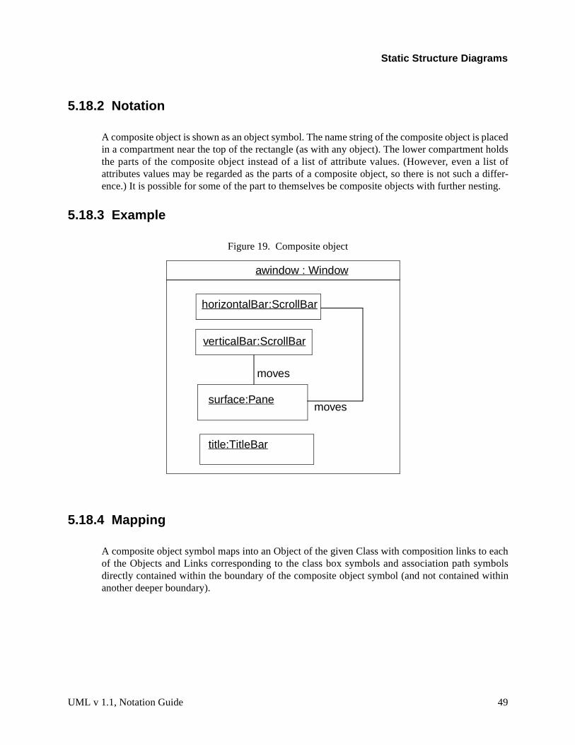
Static Structure Diagrams
placedt holdslist of
a differ-sting.
eachymbols
ithin
5.18.2 Notation
A composite object is shown as an object symbol. The name string of the composite object isin a compartment near the top of the rectangle (as with any object). The lower compartmenthe parts of the composite object instead of a list of attribute values. (However, even a attributes values may be regarded as the parts of a composite object, so there is not suchence.) It is possible for some of the part to themselves be composite objects with further ne
5.18.3 Example
Figure 19. Composite object
5.18.4 Mapping
A composite object symbol maps into an Object of the given Class with composition links toof the Objects and Links corresponding to the class box symbols and association path sdirectly contained within the boundary of the composite object symbol (and not contained wanother deeper boundary).
horizontalBar:ScrollBar
verticalBar:ScrollBar
awindow : Window
surface:Pane
title:TitleBar
moves
moves
UML v 1.1, Notation Guide 49

Static Structure Diagrams
variety as dia-
y of a
be con-ore con-phically of seg-
ociationse is a
on Role
. Thesement orne howllowing
nfusedngle The Thearrow.
5.19 ASSOCIATION
Binary associations are shown as lines connecting two class symbols. The lines may have aof adornments to show their properties. Ternary and higher-order associations are shownmonds connected to class symbols by lines.
5.20 BINARY ASSOCIATION
5.20.1 Semantics
A binary association is an association among exactly two classes (including the possibilitreflexive association from a class to itself).
5.20.2 Notation
A binary association is drawn as a solid path connecting two class symbols (both ends may nected to the same class, but the two ends are distinct). The path may consist of one or mnected segments. The individual segments have no semantic significance but may be grameaningful to a tool in dragging or resizing an association symbol. A connected sequencesments is called a path.
Un a binary association both ends may attach to the same class. The links of such an assmay connect two different objects from the same class or one object to itself. The latter careflexive association; it may be forbidden by a constraint if necessary.
The end of an association where it connects to a class is called an association role. Most of the inter-esting information about an association is attached to its roles. See the section on Associatifor details.
The path may also have graphical adornments attached to the main part of the path itselfadornments indicate properties of the entire association. They may be dragged along a segacross segments but must remain attached to the path. It is a tool responsibility to determiclose association adornments may approach a role so that confusion does not occur. The fokinds of adornments may be attached to a path:
association name
Designates the (optional) name of the association.
Shown as a name string near the path (but not near enough to an end to be cowith a rolename). The name string may have an optional small black solid triain it; the point of the triangle indicates the direction in which to read the name.name-direction arrow has no semantics significance; it is purely descriptive.classes in the association are ordered as indicated by the name-direction
50 UML v1.1, Notation Guide

Static Structure Diagrams
l;
hinperty
opera- asso-
under-e path,
ity, but away class
o indi-can be
ts, and
ssoci-ne con-straintt oneed use
(Note that there is no need for a name direction property on the association modethe ordering of the classes within the association is the name direction. This con-vention works even with n-ary associations.) A stereotype keyword witguillemets may be placed above or in front of the association name. A prostring may be placed after or below the association name.
association class symbol
Designates an association that has class-like properties, such as attributes,tions, and other associations. This is present if and only if the association is anciation class.
Shown as a class symbol attached to the association path by a dashed line.
The association path and the association class symbol represent the samelying model element which has a single name. The name may be placed on thin the class symbol, or on both (but they must be the same name).
Logically the association class and the association are the same semantic entthey are graphically distinct. The association class symbol can be draggedfrom the line but the dotted line must remain attached to both the path and thesymbol.
5.20.3 Presentation options
When two paths cross, the crossing may optionally be shown with a small semicircular jog tcate that the paths do not intersect (as in electrical circuit diagrams). Alternately crossing unmarked but connections might be shown by small dots.
5.20.4 Style guidelines
Lines may be drawn using various styles, including orthogonal segments, oblique segmencurved segments. The choice of a particular set of line styles is a user choice.
5.20.5 Options
Or-association. An or-constraint indicates a situation in which only one of several potential aations may be instantiated at one time for any single object. This is shown as a dashed linecting two or more associations, all of which must have a class in common, with the constring “{or}” labeling the dashed line. Any instance of the class may only participate in at mosof the associations at one time. Each rolename must be different. (This is simply a predefinof the constraint notation.)
UML v 1.1, Notation Guide 51

Static Structure Diagrams
corre-ng to the secondciationscribed
t of theresting
5.20.6 Example
Figure 20. Association notation
5.20.7 Mapping
An association path connecting two class symbols maps to an Association between thesponding Classes. If there is an arrow on the association name, then the Class corresponditail of the arrow is the first class and the Class corresponding to the head of the arrow is theClass in the ordering of roles of the Association; otherwise the ordering of roles in the assois undetermined. The adornments on the path map into properties of the Association as deabove. The Association is owned by the package containing the diagram.
5.21 ASSOCIATION END
5.21.1 Semantics
An association end is simply an end of an association where it connects to a class. It is parassociation, not part of the class. Each association has two or more ends. Most of the inte
Person
Manages
JobCompany
boss
worker
employeeemployer1..∗
∗
∗
0..1
Job
Account
Person
Corporation
{or}
salary
52 UML v1.1, Notation Guide

Static Structure Diagrams
element;
symbol.s are partched todorn-
ssedlicitytation.
an beorm ad. The
ns thatcitly
ed not
dupli- This
cifiedon. Anor the
infor-
sorting
sup-o, one, nav-sup-
details about an association are attached to its ends. An association end is not a separable it is just a mechanical part of an association.
5.21.2 Notation
The path may have graphical adornments at each end where the path connects to the classThese adornments indicate properties of the association related to the class. The adornmentof the association symbol, not part of the class symbol. The end adornments are either attathe end of the line or near the end of the line and must drag with it. The following kinds of aments may be attached to an association end:
multiplicity – specified by a text syntax, see detail section. Multiplicity may be suppreon a particular association or for an entire diagram. In an incomplete model the multipmay be unspecified in the model itself, in which case it must be suppressed in the no
ordering – if the multiplicity is greater than one, then the set of related elements cordered or unordered. If no indication is given, then it is unordered (the elements fset). Various kinds of ordering can be specified as a constraint on the association endeclaration does not specify how the ordering is established or maintained; operatioinsert new elements must make provision for specifying their position either impli(such as at the end) or explicitly. Possible values include:
unordered — the elements form an unordered set. This is the default and nebe shown explicitly.
ordered — the elements of the set are ordered into a list. It is still a set and cates are prohibited. This generic specification includes all kinds of ordering.may be specified by the keyword syntax: “{ordered}”.
An ordered relationship may be implemented in various ways but this is normally speas a language-specified code generation property to select a particular implementatiimplementation extension might substitute the data structure to hold the elements fgeneric specification “ordered”.
At implementation level, sorting may also be specified. It does not add new semanticmation but it expresses a design decision:
sorted — the elements are sorted based on their internal values. The actual rule is best specified as a separate constraint.
qualifier – see detail section. Qualifier is optional but not suppressible.
navigability
An arrow may be attached to the end of the path to indicate that navigation isported toward the class attached to the arrow. Arrows may be attached to zeror two ends of the path. To be totally explicit arrows may be shown wheneverigation is supported in a given direction. In practice it is often convenient to
UML v 1.1, Notation Guide 53

Static Structure Diagrams
ntation
. Thet at all.tion is
as
classot sup-
ect. Inle the thans).
ll col-re is
iginall class or a
n full
ator isd, or cre- befied
ra-
press some of the arrows and just show exceptional situations. See the preseoptions for details.
aggregation indicator
A hollow diamond is attached to the end of the path to indicate aggregationdiamond may not be attached to both ends of a line, but it need not be presenThe diamond is attached to the class that is the aggregate. The aggregaoptional but not suppressible.
If the diamond is filled, then it signifies the strong form of aggregation knowncomposition.
rolename
A name string near the end of the path. It indicates the role played by theattached to end of the path near the rolename. The rolename is optional but npressible.
interface specifier
The name of a Classifier with the syntax
‘:’ classifiername
It indicates the behavior expected of an associated object by the related objother words, the interface specifier specifies the behavior required to enabassociation. In this case, the actual class usually provides more functionalityrequired for the particular association (since it may have other responsibilitie
The use of a rolename and interface specifier are equivalent to creating a smalaboration that includes just an association and two roles, whose structudefined by the rolename and role classifier on the original association. The orassociation and classes are therefore a use of the collaboration. The originamust be compatible with the interface specifier (which can be an interfacetype).
If a interface specifier is omitted, then the association may be used to obtaiaccess to the associated class.
changeability
If the links are changeable (can be added, deleted, and moved) then no indicneeded. The property {frozen} indicates that no links may be added, deletemoved from an object (toward the end with the adornment) after the object isated and initialized. The property {addOnly} indicates that additional links mayadded (presumably the multiplicity is variable) but that links may not be modior deleted..
visibility
Specified by a visibility indicator (‘+’, ‘#’, ‘-’ or explicit keyword such as{public}) in front of the rolename. Specifies the visibility of the association t
54 UML v1.1, Notation Guide

Static Structure Diagrams
ils of
em. Toxt string
mergingggrega-ics to it.
ry from
is not
gation.
direc-two- nor-hich
eading
onfusedpecifyt this
plicityple, “*
versing in the direction toward the given rolename. See Section 5.7 for detavisibility specification.
Other properties can be specified for association roles but there is no graphical syntax for thspecify such properties use the constraint syntax near the end of the association path (a tein braces). Examples of such other properties include mutability.
5.21.3 Presentation options
If there are two or more aggregations to the same aggregate, they may be drawn as a tree bythe aggregation end into a single segment. This requires that all of the adornments on the ation ends be consistent. This is purely a presentation option; there are no additional semant
Various options are possible for showing the navigation arrows on a diagram. These can vatime to time by user request or from diagram to diagram:
Presentation option 1: Show all arrows. The absence of an arrow indicates navigationsupported.
Presentation option 2: Suppress all arrows. No inference can be drawn about naviThis is similar to any situation in which information is suppressed from a view.
Presentation options 3: Suppress arrows for associations with navigability in both tions; show arrows only for associations with one-way navigability. In this case the way navigability cannot be distinguished from no-way navigation, but the latter case ismally rare or nonexistent in practice. This is yet another example of a situation in wsome information is suppressed from a view.
5.21.4 Style guidelines
If there are multiple adornments on a single role, they are presented in the following order, rfrom the end of the path attached to the class toward the bulk of the path:
qualifier
aggregation symbol
navigation arrow
Rolenames and multiplicity should be placed near the end of the path so that they are not cwith a different association. They may be placed on either side of the line. It is tempting to sthat they will always be placed on a given side of the line (clockwise or counterclockwise) buis sometimes overridden by the need for clarity in a crowded layout. A rolename and a multimay be placed on opposite sides of the same role, or they may be placed together (for examemployee”).
UML v 1.1, Notation Guide 55

Static Structure Diagrams
role of (it may
licitys, andgative
nce oformat:
lu- char-aram-
5.21.5 Example
Figure 21. Various adornments on association roles
5.21.6 Mapping
The adornments on the end of an association path map into properties of the correspondingthe Association. In general, implications cannot be drawn from the absence of an adornmentsimply be suppressed) but see the preceding descriptions for details.
5.22 MULTIPLICITY
5.22.1 Semantics
A multiplicity item specifies the range of allowable cardinalities that a set may assume. Multipspecifications may be given for roles within associations, parts within composites, repetitionother purposes. Essentially a multiplicity specification is a subset of the open set of nonneintegers.
5.22.2 Notation
A multiplicity specification is shown as a text string comprising a comma-separated sequeinteger intervals, where an interval represents a (possibly infinite) range of integers, in the f
lower-bound .. upper-bound
where lower-bound and upper-bound are literal integer values, specifying the closed (incsive) range of integers from the lower bound to the upper bound. In addition, the staracter (*) may be used for the upper bound, denoting an unlimited upper bound. In a p
Polygon PointContains
{ordered}
3..∗1
GraphicsBundle
colortexturedensity
1
1
-bundle
+points
56 UML v1.1, Notation Guide

Static Structure Diagrams
st eval-aluate
value.
ited
mustsions,
ble to
refer-
tionbject;
eterized context (such as a template) the bounds could be expressions but they muuate to literal integer values for any actual use. Unbound expressions that do not evto literal integer values are not permitted.
If a single integer value is specified, then the integer range contains the single integer
If the multiplicity specification comprises a single star (*), then it denotes the unlimnonnegative integer range, that is, it is equivalent to *..* = 0..* (zero or more).
A multiplicity of 0..0 is meaningless as it would indicate that no instances can occur.
Expressions in some specification language can be used for multiplicities, but theyresolve to fixed integer ranges within the model (i.e., no dynamic evaluation of expresessentially the same rule on literal values as most programming language).
5.22.3 Style guidelines
Intervals should preferably be monotonically increasing. For example, “1..3,7,10” is prefera“7,10,1..3”.
Two contiguous intervals should be combined into a single interval. For example, “0..1” is pable to “0,1”.
5.22.4 Example
0..1
1
0..*
*
1..*
1..6
1..3,7..10,15,19..*
5.22.5 Mapping
A multiplicity string maps into a Multiplicity value. Duplications or other nonstandard presentaof the string itself have no effect on the mapping. Note that Multiplicity is a value and not an oit cannot stand on its own but is the value of some element property.
UML v 1.1, Notation Guide 57

Static Structure Diagrams
asso-
the finalt of thets. Thetogether other
targetncludey selectain ofrget
ibutesat initial
iation.
ify the
them
s is not
5.23 QUALIFIER
5.23.1 Semantics
A qualifier is an attribute or list of attributes whose values serve to partition the set of objectsciated with an object across an association. The qualifiers are attributes of the association.
5.23.2 Notation
A qualifier is shown as a small rectangle attached to the end of an association path between path segment and the symbol of the class that it connects to. The qualifier rectangle is parassociation path, not part of the class. The qualifier rectangle drags with the path segmenqualifier is attached to the source end of the association; that is, an object of the source class with a value of the qualifier uniquely select a partition in the set of target class objects on theend of the association (i.e., every target falls into exactly one partition).
The multiplicity attached to the target role denotes the possible cardinalities of the set ofobjects selected by the pairing of a source object and a qualifier value. Common values i“0..1” (a unique value may be selected, but every possible qualifier value does not necessarila value), “1” (every possible qualifier value selects a unique target object, therefore the domqualifier values must be finite), and “*” (the qualifier value is an index that partitions the taobjects into subsets).
The qualifier attributes are drawn within the qualifier box. There may be one or more attrshown one to a line. Qualifier attributes have the same notation as class attributes, except thvalue expressions are not meaningful.
It is permissible (although somewhat rare) to have a qualifier on each end of a single assoc
5.23.3 Presentation options
A qualifier may not be suppressed (it provides essential detail whose omission would modinherent character of the relationship).
A tool may use a lighter line for qualifier rectangles than for class rectangles to distinguishclearly.
5.23.4 Style guidelines
The qualifier rectangle should be smaller than the attached class rectangle, although thialways practical.
58 UML v1.1, Notation Guide

Static Structure Diagrams
e corre-to an
sociation model
n associ-path areon eithered line..
oes not
5.23.5 Example
Figure 22. Qualified associations
5.23.6 Mapping
The presence of a qualifier box on an end of an association path maps into a Qualifier on thsponding Association Role. Each attribute entry string inside the qualifier box maps inAttribute of the Qualifier.
5.24 ASSOCIATION CLASS
5.24.1 Semantics
An association class is an association that also has class properties (or a class that has asproperties). Even though it is drawn as an association and a class, it is really just a singleelement.
5.24.2 Notation
An association class is shown as a class symbol (rectangle) attached by a dashed line to aation path. The name in the class symbol and the name string attached to the association redundant and should be the same. The association path may have the usual adornments end. The class symbol may have the usual contents. There are no adornments on the dash
5.24.3 Presentation options
The class symbol may be suppressed (it provides subordinate detail whose omission dchange the overall relationship. The association path may not be suppressed.
Square
Chessboard
rank:Rankfile:File
Person
Bank
account #
∗0..1 1
1
UML v 1.1, Notation Guide 59

Static Structure Diagrams
rs to be
hereforeassocia- be dis-ts “asso-om thee actual
lass boxis takenoth arely. Thepertieself; they
5.24.4 Style guidelines
The attachment point should not be near enough to either end of the path that it appeaattached to the end of the path or to any of the role adornments.
Note that the association path and the association class are a single model element and thave a single name. The name can be shown on the path or the class symbol or both. If an tion class has only attributes but no operations or other associations, then the name mayplayed on the association path and omitted from the association class symbol to emphasize iciation nature.” If it has operations and other associations, then the name may be omitted frpath and placed in the class rectangle to emphasize its “class nature.” In neither case are thsemantics different.
5.24.5 Example
Figure 23. Association class
5.24.6 Mapping
An association path connecting two class boxes connected by a dashed line to another cmaps into a single Association Class element. The name of the Association Class element from the association path or the attached class box or both (they must be consistent if bpresent). The Association properties map from the association path as specified previousClass properties map from the class box as specified previously. Any constraints or proplaces on either the association path or attached class box apply to the Association Class itsmust not conflict.
Person
Manages
Company
boss
worker
employeeemployer1..∗
∗
∗
0..1
Jobsalary
60 UML v1.1, Notation Guide

Static Structure Diagrams
ore than binary
Theen the
a path) shown. Multi-
es an n-
ssumedt teams.
5.25 N-ARY ASSOCIATION
5.25.1 Semantics
An n-ary association is an association among 3 or more classes (a single class may appear monce). Each instance of the association is an n-tuple of values from the respective classes. Aassociation is a special case with its own notation.
Multiplicity for n-ary associations may be specified but is less obvious than binary multiplicity.multiplicity on a role represents the potential number of instance tuples in the association whother N-1 values are fixed.
An n-ary association may not contain the aggregation marker on any role.
5.25.2 Notation
An n-ary association is shown as a large diamond (that is, large compared to a terminator onwith a path from the diamond to each participant class. The name of the association (if any) isnear the diamond. Role adornments may appear on each path as with a binary associationplicity may be indicated, however, qualifiers and aggregation are not permitted.
An association class symbol may be attached to the diamond by a dashed line. This indicatary association that has attributes, operations, and/or associations.
5.25.3 Style guidelines
Usually the lines are drawn from the points on the diamond or the midpoint of a side.
5.25.4 Example
This example shows the record of a team in each season with a particular goalkeeper. It is athat the goalkeeper might be traded during the season and can therefore appear with differen
UML v 1.1, Notation Guide 61
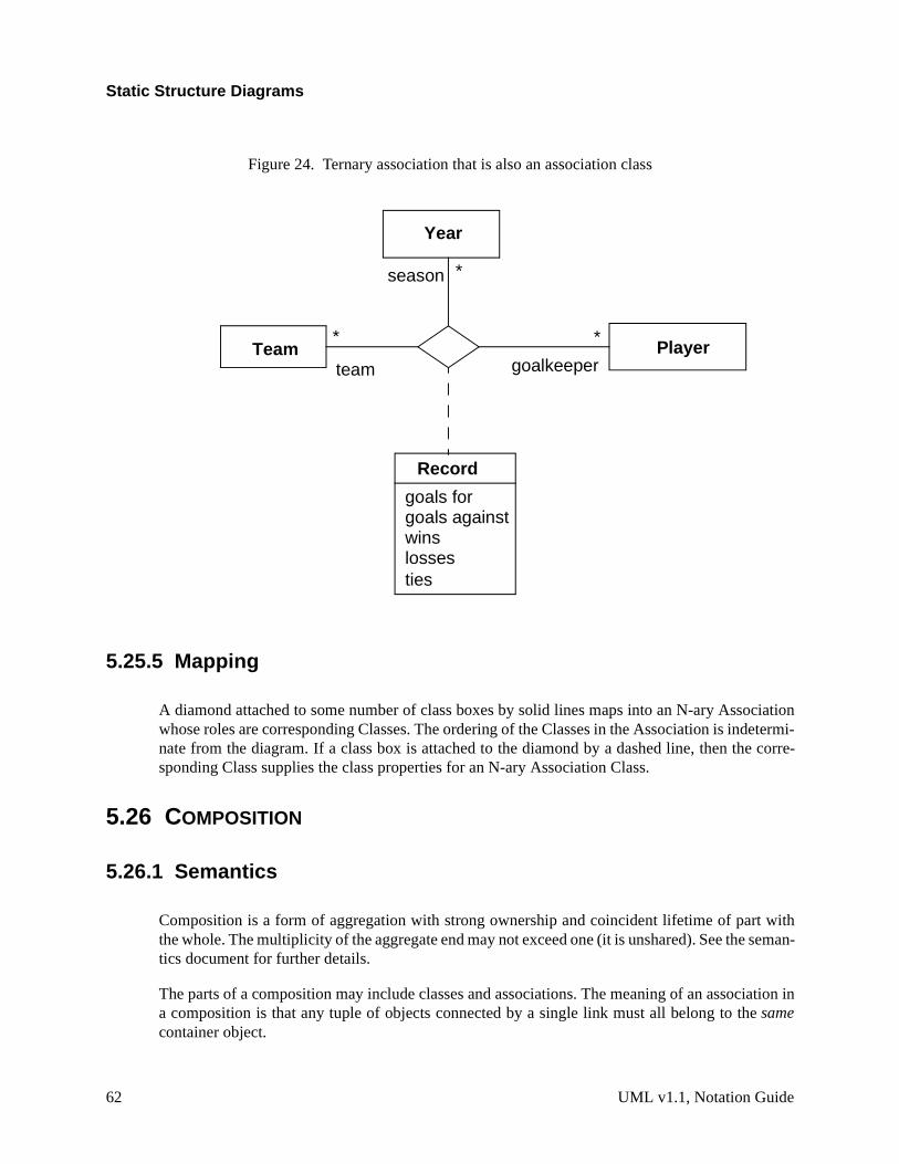
Static Structure Diagrams
ciationetermi-
e corre-
with seman-
iation in
Figure 24. Ternary association that is also an association class
5.25.5 Mapping
A diamond attached to some number of class boxes by solid lines maps into an N-ary Assowhose roles are corresponding Classes. The ordering of the Classes in the Association is indnate from the diagram. If a class box is attached to the diamond by a dashed line, then thsponding Class supplies the class properties for an N-ary Association Class.
5.26 COMPOSITION
5.26.1 Semantics
Composition is a form of aggregation with strong ownership and coincident lifetime of partthe whole. The multiplicity of the aggregate end may not exceed one (it is unshared). See thetics document for further details.
The parts of a composition may include classes and associations. The meaning of an assoca composition is that any tuple of objects connected by a single link must all belong to thesamecontainer object.
PlayerTeam
Year
Record
goals forgoals againstwinslosses
goalkeeper
∗
∗
∗
season
team
ties
62 UML v1.1, Notation Guide

Static Structure Diagrams
natelymany
mposi-in thein its part;ulti-e com-
iationy.
es of its
com-drawnosition;
n mayposite
, etc.
may beerties).e used
e class.
5.26.2 Notation
Composition may be shown by a solid filled diamond as an association role adornment. AlterUML provides a graphically-nested form that is more convenient for showing composition in cases.
Instead of using binary association paths using the composition aggregation adornment, cotion may be shown by graphical nesting of the symbols of the elements for the parts withsymbol of the element for the whole. A nested class-like element may have a multiplicity withcomposite element. The multiplicity is shown in the upper right corner of the symbol for theif the multiplicity mark is omitted then the default multiplicity is many. This represents its mplicity as a part within the composite class. A nested element may have a rolename within thposition; the name is shown in front of its type in the syntax:
rolename ‘:’ classname
This represents its rolename within its composition association to the composite.
Alternately, composition is shown by a solid-filled diamond adornment on the end of an assocpath attached to the element for the whole. The multiplicity may be shown in the normal wa
Note that attributes are, in effect, composition relationships between a class and the classattributes.
An association drawn entirely within a border of the composite is considered to be part of theposition; any objects on a single link of it must be from the same composite. An association such that its path breaks the border of the composite is not considered to be part of the company objects on a single link of it may be from the same or different composites.
Note that the notation for composition resembles the notation for collaboration. A compositiobe thought of as a collaboration in which all of the participants are parts of a single comobject.
5.26.3 Design guidelines
This notation is applicable to “class-like” model elements: classes, types, nodes, processes
Note that a class symbol is a composition of its attributes and operations. The class symbol thought of as an example of the composition nesting notation (with some special layout propHowever, attribute notation subordinates the attributes strongly within the class, so it should bwhen the structure and identity of the attribute objects themselves is unimportant outside th
UML v 1.1, Notation Guide 63

Static Structure Diagrams
5.26.4 Example
Figure 25. Different ways to show composition
Window
scrollbar [2]: Slidertitle: Headerbody: Panel
Window
scrollbar title body
scrollbar:Slider
Header Panel
2 1 1
Window
Slider
2
title:Header1
body:Panel1
111
64 UML v1.1, Notation Guide

Static Structure Diagrams
buteshes the
onding
ne com- Classesociationaluebox
is an
it may
he path;ke theireown on
ous
t for
5.26.5 Mapping
A class box with an attribute compartment maps into a Class with Attributes. Although attrimay be semantically equivalent to composition on a deep level, the mapped model distinguistwo forms.
A solid diamond on an association path maps into the composition property on the correspAssociation Role.
A class box with contained class boxes maps into a set of composition associations, that is, oposition association between the Class corresponding to the outer class box and each of thecorresponding to the enclosed class boxes. The multiplicity of the composite end of each assis 1. The multiplicity of each constituent end is 1 if not explicitly specified, otherwise it is the vspecified in the corner of the class box or specified on an association path from the outer class boundary to an inner class box.
5.27 LINKS
5.27.1 Semantics
A link is a tuple (list) of object references. Most commonly, it is a pair of object references. Itinstance of an association.
5.27.2 Notation
A binary link is shown as a path between two objects. In the case of a reflexive association,involve a loop with a single object. See Association for details of paths.
A rolename may be shown at each end of the link. An association name may be shown near tif present, it is underlined to indicate an instance. Links do not have instance names; they taidentity from the objects that they relate. Multiplicity is not shown for links because they arinstances. Other association adornments (aggregation, composition, navigation) may be shthe link roles.
A qualifier may be shown on a link. The value of the qualifier may be shown in its box.
Implementation stereotypes. A stereotype may be attached to the link role to indicate varikinds of implementation. The following stereotypes may be used:
«association» association (default, unnecessary to specify excepemphasis)
«parameter» procedure parameter
UML v 1.1, Notation Guide 65

Static Structure Diagrams
to
others as the
sifier- it is theate the
to then Asso-
«local» local variable of a procedure
«global» global variable
«self» self link (the ability of an object to send a messageitself)
N-ary link. An n-ary link is shown as a diamond with a path to each participating object. The adornments on the association and the adornments on the roles have the same possibilitiebinary link.
5.27.3 Example
Figure 26. Links
5.27.4 Mapping
The mapping depends on the kind of diagram:
Within a collaboration diagram, each link path maps to an AssociationRole between the ClasRoles corresponding to the connected class boxes. If a name is placed on the link path, thenname of the Association that is the type of the AssociationRole. Stereotypes on the path indicform of the relationship within the collaboration.
Within an object diagram, each link path maps to a Link between the Objects correspondingconnected class boxes. If a name is placed on the link path, then it is an instance of the giveciation (and the role names must match or the diagram is ill formed).
downhillSkiClub:Club Joe:Person
Jill:Person
Chris:Person
member
member
member
treasurer
officer
president
officer
66 UML v1.1, Notation Guide

Static Structure Diagrams
specific used
lass) tothe path
sub-icates
may bes for the
segment
to sub-en prop-
m mayditionalare notemantic
5.28 GENERALIZATION
5.28.1 Semantics
Generalization is the taxonomic relationship between a more general element and a more element that is fully consistent with the first element and that adds additional information. It isfor classes, packages, use cases, and other elements.
5.28.2 Notation
Generalization is shown as a solid-line path from the more specific element (such as a subcthe more general element (such as a superclass), with a large hollow triangle at the end of where it meets the more general element.
A generalization path may have a text label in the following format:
discriminator
where discriminator is the name of a partition of the subtypes of the superclass. Theclass is declared to be in the given partition. The absence of a discriminator label indthe “empty string” discriminator which is a valid value (the “default” discriminator).
Generalization may be applied to associations as well as classes, although the notation messy because of the multiple lines. An association can be shown as an association claspurpose of attaching generalization arrows.
5.28.3 Presentation options
A group of generalization paths for a given superclass may be shown as a tree with a shared (including triangle) to the superclass, branching into multiple paths to each subclass.
If a text label is placed on a generalization triangle shared by several generalization paths classes, the label applies to all of the paths. In other words, all of the subclasses share the giverties.
5.28.4 Details
The existence of additional subclasses in the model that are not shown on a particular diagrabe shown using an ellipsis (. . .) in place of a subclass. (Note: this does not indicate that adclasses may be added in the future. It indicates that additional classes exist right now but being seen. This is a notational convention that information has been suppressed, not a sstatement)
UML v 1.1, Notation Guide 67

Static Structure Diagrams
sses. Aal pathsvolved.
ses.
lasses.
tional
ncom-he iss thet are
uper-he sub-
Predefined constraints may be used to indicate semantic constraints among the subclacomma-separated list of keywords is placed in braces either near the shared triangle (if severshare a single triangle) or else near a dotted line that crosses all of the generalization lines inThe following keywords (among others) may be used:
The following constraints are predefined:
overlapping A descendent may be descended from more than one of the subclas
disjoint A descendent may not be descended from more than one of the subc
complete All subclasses have been specified (whether or not shown). No addisubclasses are expected.
incomplete Some subclasses have been specified but the list is known to be iplete. There are additional subclasses that are not yet in the model. Ta statement about the model itself. Note that this is not the same aellipsis, which states that additional subclasses exist in the model bunot shown on the current diagram.
The discriminator must be unique among the attributes and association roles of the given sclass. Multiple occurrences of the same discriminator name are permitted and indicate that tclasses belong to the same partition.
68 UML v1.1, Notation Guide

Static Structure Diagrams
antics
The use of multiple classification dynamic classification affects the dynamic execution semof the language but is not unusually apparent from a static model.5.28.5 Example
Figure 27. Styles of displaying generalization
Shape
SplineEllipsePolygon
Shape
SplineEllipsePolygon
Shared Target Style
Separate Target Style
. . .
. . .
UML v 1.1, Notation Guide 69

Static Structure Diagrams
e corre- of Gen-lass cor-m a set
opertyproperty
Figure 28. Generalization with discriminators and constraints, separate target style
Figure 29. Generalization with shared target style
5.28.6 Mapping
Each generalization path between two class boxes maps into a Generalization between thsponding Classes. A generalization tree with one arrowhead and many tails maps into a seteralizations, one between each Class corresponding to a class box on a tail and the single Cresponding to the class box on the head. That is, a tree is semantically indistinguishable froof distinct arrows; it is purely a notational convenience.
Any property string attached to a generalization arrow applies to the Generalization. A prstring attached to the head line segment on a generalization tree represents a (duplicated) on each of the individual Generalizations.
Vehicle
WindPoweredVehicle
MotorPoweredVehicle
LandVehicle
WaterVehicle
venue
venuepowerpower
SailboatTruck
{overlapping} {overlapping}
Tree
Oak Elm
{disjoint, incomplete}
Birch
species
70 UML v1.1, Notation Guide

Static Structure Diagrams
emanticiagram.
relatesndicatesment in
nt at the with an
concept
ith af theds ofereo-
ent forr toion ofct of
rame-
direction
The presence of an ellipsis (“...”) as a subclass node of a given class indicates that the smodel contains at least one subclass of the given class that is not visible on the current dNormally this indicator will be automatically maintained by an editing tool.
5.29 DEPENDENCY
5.29.1 Semantics
A dependency indicates a semantic relationship between two (or more) model elements. Itthe model elements themselves and does not require a set of instances for its meaning. It ia situation in which a change to the target element may require a change to the source elethe dependency.
5.29.2 Notation
A dependency is shown as a dashed arrow between two model elements. The model elemetail of the arrow depends on the model element at the arrowhead. The arrow may be labeledoptional stereotype and an optional name.
The following kinds of Dependency are predefined and may be indicated with keywords:
trace – Trace: a historical connection between two elements that represent the same at different levels of meaning
refine – Refinement: a historical or derivation connection between two elements wmapping (not necessarily complete) between them. A description omapping may be attached to the dependency in a note. Various kinrefinement have been proposed and can be indicated by further sttyping.
uses – Usage: a situation in which one element requires the presence of another elemits correct implementation or functioning. May be stereotyped furtheindicate the exact nature of the dependency, such as calling an operatanother class, granting permission for access, instantiating an objeanother class, etc.
bind – Binding: a binding of template parameters to actual values to create a nonpaterized element. See Section 5.12 for more details.
5.29.3 Presentation options
If one of the elements is a note or constraint then the arrow may be suppressed because the is clear (the note or constraint is the source of the arrow).
UML v 1.1, Notation Guide 71

Static Structure Diagrams
ymbols are the
5.29.4 Example
Figure 30. Various usage dependencies among classes
Figure 31. Dependencies among packages
5.29.5 Mapping
A dashed arrow maps into a Dependency between the Elements corresponding to the sattached to the ends of the arrow. The stereotype and the name (if any) attached to the arrowstereotype and name of the Dependency
«friend»ClassA ClassB
ClassC
«instantiates»
«calls»
ClassD
operationZ()«friend»
Controller
DiagramElements
DomainElements
GraphicsCore
72 UML v1.1, Notation Guide

Static Structure Diagrams
rity or
t, such
reotypesimplyen it is
5.30 DERIVED ELEMENT
5.30.1 Semantics
A derived element is one that can be computed from another one, but that is shown for clathat is included for design purposes even though it adds no semantic information.
5.30.2 Notation
A derived element is shown by placing a slash (/) in front of the name of the derived elemenas an attribute or a rolename.
5.30.3 Style guidelines
The details of computing a derived element can be specified by a dependency with the ste«derived». Usually it is convenient in the notation to suppress the dependency arrow and place a constraint string near the derived element, although the arrow can be included whhelpful.
UML v 1.1, Notation Guide 73

Static Structure Diagrams
into the
5.30.4 Example
Figure 32. Derived attribute and derived association
5.30.5 Mapping
The presence of a derived adornment (a leading “/” on the symbol name) on a symbol maps setting of the “derived” property of the corresponding Element.
Person
birthdate/age{age = currentDate - birthdate}
Company
Person
Department
WorksForDepartment
/WorksForCompany
{ Person.employer=Person.department.employer }
∗
∗∗
1
1
1employer
employerdepartment
74 UML v1.1, Notation Guide

Use Case Diagrams
nts func-
, commu-lizations
6. USE CASE DIAGRAMS
A use case diagram shows the relationship among actors and use cases within a system.
6.1 USE CASE DIAGRAM
6.1.1 Semantics
Use case diagrams show elements from the use case model. The use case model represetionality of a system or a class as mainfested to external interactors with the system.
6.1.2 Notation
A use case diagram is a graph of actors, a set of use cases enclosed by a system boundarynication (participation) associations between the actors and the use cases, and generaamong the use cases.
UML v 1.1, Notation Guide 75

Use Case Diagrams
eCase-
6.1.3 Example
Figure 33. Use case diagram
6.1.4 Mapping
A set of use case ellipses within a box with connections to actor symbols maps to a single UsModel package containing a set of UseCases and Actors with relationships among them.
Customer
Supervisor
Salespersonplaceorder
establishcredit
checkstatus
Telephone Catalog
fill orders
Shipping Clerk
76 UML v1.1, Notation Guide

Use Case Diagrams
ted byrs (called
casesn points
l items
rt of aoutsiders.
6.2 USE CASE
6.2.1 Semantics
A use case is a coherent unit of functionality provided by a system or class as manifessequences of messages exchanged among the system and one or more outside interactoactors) together with actions performed by the system.
6.2.2 Notation
A use case is shown as an ellipse containing the name of the use case.
An extension point is a location within a use case at which action sequences from other usemay be inserted. Each extension point must have a unique name within a use case. Extensiomay be listed in a compartment of the use case with the heading extension points.
6.2.3 Presentation options
The name of the use case may be placed below the ellipse.
6.2.4 Style guidelines
Use case names should follow capitalization and punctuation guidelines used for behaviorain the same model.
6.2.5 Mapping
A use case symbol maps to a UseCase with the given name (if any).
An extension point maps into an ExtensionPoint within the UseCase.
6.3 ACTOR
6.3.1 Semantics
An actor is a role of object or objects outside of a system that interacts directly with it as pacoherent work unit (a use case). An Actor element characterizes the role played by an object; one physical object may play several roles and therefore be modeled by several acto
UML v 1.1, Notation Guide 77

Use Case Diagrams
reotype
ses in
s.
nship
nstancen) thee case
e of the
between
se caseends».
e doing
6.3.2 Notation
An actor may be shown as a class rectangle with the stereotype “actor”. The standard steicon for an actor is the “stick man” figure with the name of the actor below the figure.
6.3.3 Style guidelines
Actor names should follow capitalization and punctuation guidelines used for types and clasthe same model.
6.3.4 Mapping
An actor symbol maps to an Actor with the given name.
6.4 USE CASE RELATIONSHIPS
6.4.1 Semantics
There are several standard relationships among use cases or between actors and use case
Communicates – The participation of an actor in a use case. This is the only relatiobetween actors and use cases.
Extends – An extends relationships from use case A to use case B indicates that an iof use case B may include (subject to specific conditions specified in the extensiobehavior specified by A. Behavior specified by several extenders of a single target usmay occur within a single use case instance.
Uses – A uses relationship from use case A to use case B indicates that an instancuse case A will also include the behavior as specified by B.
6.4.2 Notation
The communication relationship between an actor and a use case is shown as a solid line the actor and the use case.
An “extends” relationship between use cases is shown by a generalization arrow from the uproviding the extension to the base use case. The arrow is labeled with the stereotype «ext
A “uses” relationship between use cases is shown by a generalization arrow from the use casthe use to the use case being used. The arrow is labeled with the stereotype «uses».
78 UML v1.1, Notation Guide

Use Case Diagrams
wn by anmenta-n invis-
to see
etween
The relationship between a use case and its external interaction sequences are usually shoinvisible hyperlink to sequence diagrams. The relationship between a use case and its impletion may be shown as a refinement relationship to a collaboration but may also be shown as aible hyperlink. The expectation is that a tool will support the ability to “zoom into” a use case its scenarios and/or implementation as an interaction.
6.4.3 Example
Figure 34. Use case relationships
6.4.4 Mapping
A path between use case and/or actor symbols maps into the corresponding relationship bthe corresponding Elements, as described above.
Place Order
additional requests
OrderProduct
SupplyCustomer
Data
ArrangePayment
«uses»«uses»«uses»
RequestCatalog
«extends»extension points
UML v 1.1, Notation Guide 79

Sequence Diagrams
gramsticular
s thehange
s.
nd in anwithout
fferentme spec-bjectsn.
g objects
rizontalnsions
cations of the
otationtions
7. SEQUENCE DIAGRAMS
7.1 KINDS OF INTERACTION DIAGRAMS
A pattern of interaction among objects is shown on an interaction diagram. Interaction diacome in two forms based on the same underlying information but each emphasizing a paraspect of it: sequence diagrams and collaboration diagrams.
A sequence diagram shows an interaction arranged in time sequence. In particular, it showobjects participating in the interaction by their “lifelines” and the messages that they excarranged in time sequence. It does not show the associations among the objects.
Sequence diagrams come in several slightly different formats intended for different purpose
A sequence diagram can exist in a generic form (describes all the possible sequences) ainstance form (describes one actual sequence consistent with the generic form). In cases loops or branches, the two forms are isomorphic.
Sequence diagrams and collaboration diagrams express similar information but show it in diways. Sequence diagrams show the explicit sequence of messages and are better for real-tiifications and for complex scenarios. Collaboration diagrams show the relationships among oand are better for understanding all of the effects on a given object and for procedural desig
7.2 SEQUENCE DIAGRAM
7.2.1 Semantics
A sequence diagram represents an Interaction, which is a set of messages exchanged amonwithin a collaboration to effect a desired operation or result.
7.2.2 Notation
A sequence diagram has two dimensions: the vertical dimension represents time, the hodimension represents different objects. Normally time proceeds down the page. (The dimemay be reversed if desired.) Usually only time sequences are important but in real-time applithe time axis could be an actual metric. There is no significance to the horizontal orderingobjects. Objects can be grouped into “swimlanes” on a diagram.
See subsequent sections for details of the contents of a sequence diagram.
(Note that much of this notation is drawn directly from the Object Message Sequence Chart nof Buschmann, Meunier, Rohnert, Sommerlad, and Stal, which is itself derived with modificafrom the Message Sequence Chart notation.)
80 UML v1.1, Notation Guide

Sequence Diagrams
o pro-oes not
objects
e) can
7.2.3 Presentation options
Note that the horizontal ordering of the lifelines is arbitrary. Often call arrows are arranged tceed in one direction across the page, but this is not always possible and the ordering dconvey information.
The axes can be interchanged, so that time proceeds horizontally to the right and different are shown as horizontal lines.
Various labels (such as timing marks, descriptions of actions during an activation, and so onbe shown either in the margin or near the transitions or activations that they label.
7.2.4 Example
Figure 35. Simple sequence diagram with concurrent objects
caller exchange
lift receiver
dial tone
dial digit
a
b
c
{b - a < 1 sec.}
{c - b < 10 sec.}
. . .
d
d'
route
{d' - d< 5 sec.}
receiver
phone ringsringing tone
answer phone
stop ringingstop tone
The call isrouted throughthe network.
At this pointthe partiescan talk.
UML v 1.1, Notation Guide 81

Sequence Diagrams
n
t, some
Figure 36. Sequence diagram with focus of control, conditional, recursion, creation, destructio
7.2.5 Mapping
(This section summarizes the mapping for the sequence diagram and the elements within iof which are described in subsequent sections.)
[x>0] foo(x)
[x<0] bar(x)
doit(z)doit(w)
more()
ob1:C1
ob2:C2
ob3:C3 ob4:C4
op()
82 UML v1.1, Notation Guide

Sequence Diagrams
ct boxe andThed in thes into annects;iagrameen therrowiagram
to theargetw; oth-
geshe map-
on theas, acti-
ration)activa-owessage atme
ecessorbecomeon with
y playnce and
. There
A sequence diagram maps into an Interaction and an underlying Collaboration. Each objewith its lifeline maps into a ClassifierRole; the name field maps into the ClassifierRole namthe type field maps into the type association from the role to the Classifier with the given name. associations among roles are not shown on the sequence diagram; they must be obtainemodel from a complementary collaboration diagram or other means. A message arrow mapMessage between the ClassifierRoles corresponding to the two lifelines that the arrow counless the correct AssociationRole can be determined from a complementary collaboration dor other means, the Message must be attached to a dummy AssociationRole implied betwtwo ClassifierRoles for lack of complete information. A timing label placed on the level of an aendpoint maps into the name of the corresponding Message. A constraint placed on the dmaps into a Constraint on the entire Interaction.
An object symbol placed within the frame of the diagram maps into a CreateAction attachedMessage corresponding to the incoming arrow. If an object termination symbol (“X”) is the tof an arrow, it maps into a DestroyAction attached to the Message corresponding to the arroerwise it maps into a TerminateAction
On a diagram with concurrent objects, a predecessor association is established between Messacorresponding to successive arrows in the vertical sequence. In case of concurrent arrows, tping to a predecessor sequence may be ambiguous and may require additional information.
On a procedural sequence diagram (one with focus of control and calls) subsequent arrowssame lifeline map into Messages obeying the predecessor association. An arrow to the head of focus of control region establishes a nested activation; it maps into a Message (synchronouvation) with associated CallAction (holding the arguments and referencing the target Opebetween the ClassifierRoles corresponding to the lifelines. All arrows departing the nested tion map into Messages with an activation Association to the Message corresponding to the arrat the head of the activation. A return arrow departing the end of the activation maps into a M(synchronous, reply) with an activation Association to the Message corresponding to the arrowthe head of the activation and a predecessor association to the previous message within the saactivation. A return must be the final message within a predecessor chain; it is not the predof any message. Any guard conditions or iteration conditions attached to a message arrow recurrence values of the Message. The operation name is used to select the target Operatithe given name. The operation arguments become argument Expressions on the Action.
7.3 OBJECT LIFELINE
7.3.1 Semantics
A Role is a slot for an object within a collaboration that describes the type of object that mathe role and describes its relationships to other Roles. Within a sequence diagram the existeduration of the object in a role is shown, but the relationships among the roles is not shownare ClassifierRoles and AssociationRoles.
UML v 1.1, Notation Guide 83

Sequence Diagrams
ts theriod of it goesine; ifowheadarked
ruction)saction trans-
aratether at
ctiontion in
hoset nextssagel flowitiates
7.3.2 Notation
An object role is shown as a vertical dashed line called the “lifeline”. The lifeline represenexistence of the object at a particular time. If the object is created or destroyed during the petime shown on the diagram, then its lifeline starts or stops at the appropriate point; otherwisefrom the top to the bottom of the diagram. An object symbol is drawn at the head of the lifelthe object is created during the diagram, then the message that creates it is drawn with its arron the object symbol. If the object is destroyed during the diagram, then its destruction is mby a large “X”, either at the message that causes the destruction or (in the case of self-destat the final return message from the destroyed object. An object that exists when the transtarts is shown at the top of the diagram (above the first arrow). An object that exists when theaction finishes has its lifeline continue beyond the final arrow.
The lifeline may split into two or more concurrent lifelines to show conditionality. Each septrack corresponds to a conditional branch in the message flow. The lifelines may merge togesome subsequent point.
7.3.3 Example
See Figure 36.
7.3.4 Mapping
See Section 7.2.5.
7.4 ACTIVATION
7.4.1 Semantics
An activation (focus of control) shows the period during which an object is performing an aeither directly or through a subordinate procedure. It represents both the duration of the actime and the control relationship between the activation and its callers (stack frame).
7.4.2 Notation
An activation is shown as a tall thin rectangle whose top is aligned with its initiation time and wbottom is aligned with its completion time. The action being performed may be labeled in texto the activation symbol or in the left margin, depending on style; alternately the incoming memay indicate the action, in which case it may be omitted on the activation itself. In proceduraof control, the top of the activation symbol is at the tip of an incoming message (the one that inthe action) and the base of the symbol is at the tail of a return message.
84 UML v1.1, Notation Guide

Sequence Diagrams
ws thelevant.
ure) is
activerds, allrsive call rightn arbi-
on that
ne of on theal) andequencece dia-re nec-or iden-.
In the case of concurrent objects each with their own threads of control, an activation shoduration when each object is performing an operation; operations by other objects are not reIf the distinction between direct computation and indirect computation (by a nested procedunimportant, the entire lifeline may be shown as an activation.
In the case of procedural code, an activation shows the duration during which a procedure isin the object or a subordinate procedure is active, possibly in some other object. In other woof the active nested procedure activations may be seen at a given time. In the case of a recuto an object with an existing activation, the second activation symbol is drawn slightly to theof the first one, so that they appear to “stack up” visually. (Recursive calls may be nested to atrary depth.)
7.4.3 Example
See Figure 36.
7.4.4 Mapping
See Section 7.2.5.
7.5 MESSAGE
7.5.1 Semantics
A message is a communication between objects that conveys information with the expectatiaction will ensue. The receipt of a message is one kind of event.
7.5.2 Notation
A message is shown as a horizontal solid arrow from the lifeline of one object to the lifelianother object. In case of a message from an object to itself, the arrow may start and finishsame object symbol. The arrow is labeled with the name of the message (operation or signits argument values. The arrow may also be labeled with a sequence number to show the sof the message in the overall interaction. Sequence numbers are often omitted in sequengrams, in which the physical location of the arrow shows the relative sequences, but they aessary in collaboration diagrams. Sequence numbers are useful on both kinds of diagrams ftifying concurrent threads of control. A message may also be labeled with a guard condition
UML v 1.1, Notation Guide 85

Sequence Diagrams
th only
arrow.
endssages;ontrolitly.
(waitno-wait
ired ton andmptiong else slanted
ed bynstruct
ion. Forocedure, there may be can be
-level
vationntrol withished
7.5.3 Presentation options
Variation: Asynchronous. An asynchronous message is drawn with a half-arrowhead (one wione wing instead of two).
Variation: Call. A procedure call is drawn as a full arrowhead. A return is shown as a dashed
Variation: In a procedural flow of control, the return arrow may be omitted (it is implicit at theof an activation). It is assumed that every call has a paired return after any subordinate methe return value can be shown on the initial message line. For nonprocedural flow of c(including parallel processing and asynchronous messages) returns should be shown explic
Variation: In a concurrent system, a full arrowhead shows the yielding of a thread of controlsemantics) and a half arrowhead shows the sending of a message without yielding control (semantics).
Variation: Normally message arrows are drawn horizontally. This indicates the duration requsend the message is “atomic”, that is, it is brief compared to the granularity of the interactiothat nothing else can “happen” during the message transmission. This is the correct assuwithin many computers. If the message requires some time to arrive, during which somethincan occur (such as a message in the opposite direction) then the message arrow may bedownward so that the arrowhead is below the arrow tail.
Variation: Branching. A branch is shown by multiple arrows leaving a single point, each labela guard condition. Depending on whether the guard conditions are mutually exclusive, the comay represent conditionality or concurrency.
Variation: Iteration. A connected set of messages may be enclosed and marked as an iterata scenario, the iteration indicates that the set of messages can occur multiple times. For a prthe continuation condition for the iteration may be specified at the bottom of the iteration. Ifis concurrency, then some messages in the diagram may be part of the iteration and otherssingle execution. It is desirable to arrange a diagram so that the messages in the iterationenclosed together easily.
Variation: A lifeline may subsume an entire set of objects on a diagram representing a highview.
Variation: A distinction may be made between a period during which an object has a live actiand a period in which the activation is actually computing. The former (during which it has coinformation on a stack but during which control resides in something that it called) is shownthe ordinary double line; the latter (during which it is the top item on the stack) may be distinguby shading the region.
7.5.4 Mapping
See Section 7.2.5.
86 UML v1.1, Notation Guide

Sequence Diagrams
be usedmic) or
r a tran-message time atendeduencee mayge line is
agram.
7.6 TRANSITION TIMES
7.6.1 Semantics
A message may have a sending time and a receiving time. These are formal names that maywithin constraint expressions. The two may be the same (if the message is considered atodifferent (if its delivery is nonatomic).
7.6.2 Notation
A transition instance (such as a message in a sequence diagram or a collaboration diagram osition in a state machine) may be given a name. The name represents the time at which a is sent (example: A). In cases where the delivery of the message in not instantaneous, thewhich the message is received is indicated by the transition name with a prime sign app(example: A'). The name may be shown in the left margin aligned with the arrow (on a seqdiagram) or near the tail of the message flow arrow (on a collaboration diagram). This nambe used in constraint expressions to designate the time the message was sent. If the messaslanted, then the primed-name indicates the time at which the message is received.
Constraints may be specified by placing Boolean expressions in braces on the sequence di
7.6.3 Example
See Figure 35.
7.6.4 Mapping
See Section 7.2.5.
UML v 1.1, Notation Guide 87

Collaboration Diagrams
on andlation-
me as aetermined
ction toee only
ses, pro-truct is
of pur-g.
ich theiriagrams’s static
different param- in eachructures most are free
ration
ts anda singlely. The
ssage
8. COLLABORATION DIAGRAMS
A collaboration diagram shows an interaction organized around the objects in the interactitheir links to each other. Unlike a sequence diagram, a collaboration diagram shows the reships among the object roles. On the other hand, a collaboration diagram does not show tiseparate dimension, so the sequence of messages and the concurrent threads must be dusing sequence numbers.
8.1 COLLABORATION
8.1.1 Semantics
Behavior is implemented by sets of objects that exchange messages within an overall interaaccomplish a purpose. To understand the mechanisms used in a design, it is important to sthe objects and the messages involved in accomplishing a purpose or a related set of purpojected from the larger system of which they are part for other purposes. Such a static conscalled a collaboration.
A collaboration is a set of participants and relationships that are meaningful for a given set poses. The identification of participants and their relationships does not have global meanin
A collaboration may be attached to an operation or a use case to describe the context in whbehavior occurs. The actual behavior may be specified in interactions, such as sequence dor collaboration diagrams. A collaboration may also be attached to a class to define the classstructure.
A parameterized collaboration represents a design construct that can be used repeatedly in designs. The participants in the collaboration, including the classes and relationships, can beeters of the generic collaboration. The parameters are bound to particular model elementsinstantiation of generic collaboration. Such a parameterized collaboration can capture the stof a design pattern (note that a design pattern involves more than structural aspects). Whereacollaborations can be anonymous because they are attached to a named entity, patternsstanding design constructs that must have names.
A collaboration may be expressed at different levels of granularity. A coarse-grained collabomay be refined to produce another collaboration that has a finer granularity.
8.1.2 Notation
The description of behavior involves two aspects: the structural description of its participanthe behavioral description of its execution. The two aspects are often described together on diagram but at times it is useful to describe the structural and behavioral aspects separatestructure of objects playing roles in a behavior and their relationships is called a collaboration. Acollaboration shows the context in which interaction occurs. The dynamic behavior of the me
88 UML v1.1, Notation Guide

Collaboration Diagrams
n inter-eld dif-
rticularin a col-
tachedludingribe anrdinarystroyedion androm the
proce- tohead
a linecannot
tribute
a proce-nesting.sequence
,pera-
sequences exchanged among objects to accomplish a specific purpose is called an interaction. Acollaboration is shown by a collaboration diagram without messages. By adding messages, aaction is shown. Different sets of messages may be applied to the same collaboration to yiferent interactions.
8.2 COLLABORATION DIAGRAM
8.2.1 Semantics
A collaboration diagram represents a Collaboration, which is a set of objects related in a pacontext, and an Interaction, which is a set of messages exchanged among the objects withlaboration to effect a desired operation or result.
8.2.2 Notation
A collaboration diagram is a graph of references to objects and links with message flows atto its links. The diagram shows the objects relevant to the performance of an operation, incobjects indirectly affected or accessed during the operation. The collaboration used to descoperation includes its arguments and local variables created during its execution as well as oassociations. Objects created during the execution may be designated as {new}; objects deduring the execution maybe designated as {destroyed}; objects created during the executthen destroyed may be designated as {transient}. These changes in life state are derivable fdetailed messages sent among the objects; the are provided as notational conveniences.
The diagram also shows the links among the objects, including transient links representingdure arguments, local variables, and self links. Because collaboration diagrams are often usedhelp design procedures, they typically show navigability using arrowheads on links. (An arrowon a line between object boxes indicates a link with one-way navigability. An arrow next to indicates a message flowing in the given direction over the link. Obviously a message arrow flow backwards over a one-way link.)
Individual attribute values are usually not shown explicitly. If messages must be sent to atvalues, the attributes should be modeled using associations instead.
The internal messages that implement a method are numbered starting with number 1. For dural flow of control the subsequent message numbers are nested in accordance with call For a nonprocedural sequence of messages exchanged among concurrent objects all the numbers are at the same level (that is, they are not nested).
A collaboration diagram without messages shows the context in which interactions can occurwithout showing any specific interactions. It might be used to show the context for a single otion or even for all of the operations of a class or group of classes.
UML v 1.1, Notation Guide 89

Collaboration Diagrams
pose itn as aesign
the pat-
dehavioral
8.2.3 Example
Figure 37. Collaboration diagram
8.2.4 Mapping
A collaboration diagram maps to a Collaboration with a superimposed Interaction.
8.3 PATTERN STRUCTURE
8.3.1 Semantics
A collaboration can be used to specify the implementation of design constructs. For this puris necessary to specify its context and interactions. It is also possible to view a collaboratiosingle entity from the “outside.” For example, this could be used to identify the presence of dpatterns within a system design. A pattern is a parameterized collaboration; in each use of tern, actual classes are substituted for the parameters in the pattern definition.
Note that patterns as defined in Design Patterns by Gamma, Helm, Johnson, and Vlissides inclumuch more than structural descriptions. UML describes the structural aspects and some be
:Controller
wire: Wire
1: displayPositions(window)
left: Bead
wire
redisplay():Window
i-1 i
right: Bead
1.1.1b: r1:=position()1.1.1a: r0 := position()
1.1.2: create(r0,r1)
window
«parameter»window
1.1*[i:=1..n]: drawSegment(i) :Line {new}«local»line
1.1.3: display(window)
1.1.3.1: add(self)
contents {new}
«self»
90 UML v1.1, Notation Guide

Collaboration Diagrams
atterns,
tion. Ading onration.entsmetersefore aes that
by anrameter name
aspects of design patterns, but UML notation does not include other important aspects of psuch as usage trade-offs or examples. These must be expressed in text or tables.
8.3.2 Notation
A use of a collaboration is shown as a dashed ellipse containing the name of the collaboradashed line is drawn from the collaboration symbol to each of the objects or classes (depenwhether it appears within an object diagram or a class diagram) that participate in the collaboEach line is labeled by the role of the participant. The roles correspond to the names of elemwithin the context for the collaboration; such names in the collaboration are treated as parathat are bound to specify elements on each occurrence of the pattern within a model. Thercollaboration symbol can shown the use of a design pattern together with the actual classoccur in that particular use of the pattern.
Figure 38. Use of a collaboration
8.3.3 Mapping
A collaboration usage symbol maps into a Collaboration. For each class symbol attachedarrow to the pattern occurrence symbol, the corresponding Class is bound to the template pathat is the type association target of the ClassifierRole in the Pattern with the name equal to theon the arrow.
Observer
SlidingBarIconhandler
CallQueue subject
queue: List of Callsource: ObjectwaitAlarm: Alarm
reading: Realcolor: Colorrange: Interval
handler.reading = length (subject.queue)
capacity: Integer
range = (0 .. capacity)
UML v 1.1, Notation Guide 91

Collaboration Diagrams
a par-collab-
ighbor must be
eferenceabo-r roles roles
usu- addedopera-e col-perationly duringnvolved, mes-
hows a
f thecan be
n are notoration
labora- are rel-llabora-t from
usiness
8.4 COLLABORATION CONTENTS
The contents of a collaboration are modeling elements that interact within a given context forticular purpose, such as performing an operation or a use case; it is a “society of objects”. A oration is a fragment of a larger complete model that is intended for a particular purpose.
8.4.1 Semantics
A collaboration shows one or more roles together with their contents, associations, and neroles, plus additional relationships and classes as needed. To use a collaboration, each rolebound to an actual class that can support the operations required of the role.
8.4.2 Notation
A collaboration is shown as a graph of class references and association references. Each ris a role of the collaboration; that is, each entity is playing a role within the context of the collration, a role that is only part of its full description. The names of the objects represent theiwithin the collaboration. A collaboration is a prototype; in each use of the collaboration theare bound to actual objects. There are several ways to show the diagram:
Methods. If the collaboration shows the implementation of an operation (a method), then it isally drawn as a separate collaboration diagram including context to which message flow isto obtain an interaction. The collaboration for the operation includes the target object of the tion and any other objects that it calls on, directly or indirectly, to implement the operation. Thlaboration includes the objects present before the operation, the objects present after the o(these may be the same or mostly the same as the ones before), and objects that exist onthe operation; these may be marked as «new», «destroyed», and «transient». Only objects iin the operation implementation need be shown. To show the implementation of an operationsage flows are superimposed on the links between objects in the collaboration; each flow sstep within the method for the operation (see Section 8.9).
Classes. A collaboration is normally defined for a single operation. By taking the union of all ocollaborations for all of the operations of a class, an overall collaboration for the entire class shown. This collaboration shows all of the context for the implementation of the class.
In both cases the usual assumption is that objects and classes not shown on the collaboratioaffected by the operation. (It is not always safe to assume that all of the objects on a collabdiagram are used by the operation, however.)
Different collaborations may be devised for the same class for different purposes. Each coltion may show a somewhat different subset of attributes, operators, and related objects thatevant to each purpose. Inasmuch as actual operations often fall into related groups, each cotion might specify a consistent view shared by several operations that is somewhat differenthe view needed by other operations on the same type. Similarly, the model of types in a b
92 UML v1.1, Notation Guide

Collaboration Diagrams
a par-
ion) by implicitaccom-
amongntation is, thences areor con- a par-
formatsipating do notl aspecttion ofs show
ticulard in the
organization can often be divided into several collaborations, each from the point of view of ticular stakeholder.
8.5 INTERACTIONS
A collaboration of objects interacts to accomplish a purpose (such as performing an operatexchanging messages. The messages may include both signals and calls, as well as moreinteraction through conditions and time events. A specific pattern of message exchanges to plish a specific purpose is called an interaction.
8.5.1 Semantics
An interaction is a behavioral specification that comprises a sequence of message exchangesa set of objects within a collaboration to accomplish a specific purpose, such as the implemeof an operation. To specify an interaction, it is first necessary to specify a collaboration, thatestablish the objects that interact and their relationships. Then the possible interaction sequespecified. These can be specified in a single description containing conditionals (branches ditional signals), or they can be specified by supplying multiple descriptions, each describingticular path through the possible execution paths.
8.5.2 Notation
Interactions are shown as sequence diagrams or as collaboration diagrams. Both diagramshow the execution of collaborations. However, sequence diagrams only show the particobjects and do not show their relationships to other objects or their attributes, therefore theyfully show the context aspect of a collaboration. Sequence diagrams do show the behavioraof collaborations explicitly, including the time sequence of message and explicit representamethod activations. Sequence diagrams are described in Chapter 7. Collaboration diagramthe full context of an interaction, including the objects and their relationships relevant to a parinteraction, so they are often better for design purposes. Collaboration diagrams are describefollowing sections.
8.5.3 Example
See Collaboration Diagram section for a collaboration underlying an interaction.
UML v 1.1, Notation Guide 93

Collaboration Diagrams
y playciation-
r, thate
shown.
rmally precede
r as an class.
upper
corre-ence of
y indi-
name.
8.6 COLLABORATION ROLES
8.6.1 Semantics
A Role is a slot for an object within a collaboration that describes the type of object that mathe role and describes its relationships to other Roles. There are ClassifierRoles and AssoRoles.
8.6.2 Notation
A collaboration role is shown using the notation for an object or a link. Keep in mind, howevein the context of a collaboration these represent roles that bind to actual objects or links when thcollaboration is used, not actual objects and links.
A class role is shown as a class rectangle symbol. Normally only the name compartment is The name compartment contains the string:
classRoleName : Classifiername
The classname can include a full pathname of enclosing packages, if necessary (a tool will nopermit shortened pathnames to be used when they are unambiguous). The package namesthe classname and are separated by double colons. For example:
display_window: WindowingSystem::GraphicWindows::WindowA stereotype for the class may be shown textually (in guillemets above the name string) oicon in the upper right corner. The stereotype for an object must match the stereotype for its
A class role representing a set of objects includes a multiplicity indicator (such as “*”) in the right corner of the class box.
An association role is shown as a path between two class role symbols. If the name of thesponding association is included it is underlined. Rolenames are not underlined. Even in absunderlining a line connecting class roles is an association role.
If one end of the association role path is connected to a multiple class role, then a multiplicitcator may be placed on that end to emphasize the multiplicity.
8.6.3 Presentation options
The name of the object may be omitted. In this case the colon should be kept with the classThis represents an anonymous object of the given class given identity by its relationships.
The class of the object may be suppressed (together with the colon).
94 UML v1.1, Notation Guide

Collaboration Diagrams
es thees
o show modeled to
y anddicatesct.
: an iter-h indi- mes-l object;lied.l code)tioned
iobjectsimple
which
8.6.4 Example
See Figure 37.
8.6.5 Mapping
The object symbol in a collaboration diagram maps to a ClassifierRole whose name matchobject part of the name string; the role has a type Association to a Classifier whose name matchthe type part of the name string.
8.7 MULTIOBJECT
8.7.1 Semantics
A multiobject represents a set of objects on the “many” end of an association. This is used toperations that address the entire set, rather than a single object in it. The underlying staticis unaffected by this grouping. This corresponds to an association with multiplicity “many” usaccess a set of associated objects.
8.7.2 Notation
A multiobject is shown as two rectangles in which the top rectangle is shifted slightly verticallhorizontally to suggest a stack of rectangles. A message arrow to the multiobject symbol ina message to the set of objects, for example, a selection operation to find an individual obje
To perform an operation on each object in a set of associated objects requires two messagesation to the multiobject to extract links to the individual objects, then a message sent to eacvidual object using the (temporary) link. This may be elided on a diagram by combining thesages into a single message that includes an iteration and an application to each individuathe target rolename takes a “many” indicator (*) to show that many individual links are impAlthough this may be written as a single message, in the underlying model (and in any actuait requires the two layers of structure (iteration to find links, message using each link) menpreviously.
An object from the set is shown as a normal object symbol, but it may be attached to the multsymbol using a composition link to indicate that it is part of the set. A message arrow to the object symbol indicates a message to an individual object.
Typically a selection message to a multiobject returns a reference to an individual object, tothe original sender then sends a message.
UML v 1.1, Notation Guide 95

Collaboration Diagrams
itly
ssivey sendgram, a
on.
al kinds
active
8.7.3 Example
Figure 39. Multiobject
8.7.4 Mapping
A multiobject symbol maps to a ClassifierRole with multiplicity “many” (or whatever is explicspecified). In other respects it maps the same as an object symbol.
8.8 ACTIVE OBJECT
An active object is one that owns a thread of control and may initiate control activity. A paobject is one that holds data but that does not initiate control. However, a passive object mamessages in the process of processing a request that it has received. In a collaboration diaClassifierRole that is an active class represents the active objects that occur during executi
8.8.1 Semantics
An active object is an object that owns a thread of control. Processes and tasks are traditionof active objects.
8.8.2 Notation
A role for an active object is shown as an object symbol with a heavy border. Frequently object roles are shown as composites with embedded parts.
The property keyword {active} may also be used to indicate an active object.
servers:Server
:ServeraServer {local}
client
1: aServer:=find(specs)
2: process(request)
96 UML v1.1, Notation Guide

Collaboration Diagrams
ciation
8.8.3 Example
Figure 40. Composite active object
8.8.4 Mapping
An active object symbol maps as an object symbol does, with the addition that the active propertyis set.
A nested object symbol (active or not) maps into a Classifierrole that has a composition assoto the roles corresponding to its contents, as described under Composition.
job
:FactoryJobMgr
:FactoryScheduler
currentJob:TransferJob
:Factory Manager
1: start(job)
A2,B2 / 2: completed(job)
{local} job
:Oven:Robot
1 / A1: start(job)1 / B1: start(job)
A2: completedB2: completed
UML v 1.1, Notation Guide 97

Collaboration Diagrams
n of an active
is used arrow.
s of
ence with
tiveuence
p in
d toroce-
ut
ng of they, and
8.9 MESSAGE FLOWS
8.9.1 Semantics
A message flow is the sending of a message from one object to another. The implementatiomessage may take various forms, such as a procedure call, the sending of a signal betweethreads, the explicit raising of events, and so on.
8.9.2 Notation
A message flow is shown as a labeled arrow placed near a link. The meaning is that the linkto transport or otherwise implement the delivery of the message to the target object. Thepoints along the link in the direction of the target object (the one that receives the message)
Control flow type. The following arrowhead variations may be used to show different kindmessages:
filled solid arrowhead procedure call or other nested flow of control. The entire nested sequis completed before the outer level sequence resumes. May be usedordinary procedure calls. May also be used with concurrently acobjects when one of them sends a signal and waits for a nested seqof behavior to complete.
stick arrowheadFlat flow of control. Each arrow shows the progression to the next stesequence. Normally all of the messages are asynchronous.
half stick arrowheadasynchronous flow of control. Used instead of the stick arrowheaexplicitly show an asynchronous message between two objects in a pdural sequence.
other variationsother kinds of control may be shown, such as “balking” or “time-out”, bthese are treated as extensions to the UML core
Message label. The label has the following syntax:
predecessor guard-condition sequence-expression return-value := message-name argument-list
The label indicates the message sent, its arguments and return values, and the sequencimessage within the larger interaction, including call nesting, iteration, branching, concurrencsynchronization.
98 UML v1.1, Notation Guide

Collaboration Diagrams
a slash
atch the
quencehe guard
implicitfix form number
llowedion. Ifllowing
ceduralesting.
re con-thin acti-
essages
use mayeant toribe its
nditioning lan-
Predecessor. The predecessor is a comma-separated list of sequence numbers followed by (‘/’):
sequence-number ‘,’ . . . ‘/’
The clause is omitted if the list is empty.
Each sequence-number is a sequence-expression without any recurrence terms. It must msequence number of another message.
The meaning is that the message flow is not enabled until all of the message flows whose senumbers are listed have occurred (a thread can go beyond the required message flow and tremains satisfied). Therefore the guard condition represents a synchronization of threads.
Note that the message corresponding to the numerically preceding sequence number is anpredecessor and need not be explicitly listed. All of the sequence numbers with the same prea sequence; the numerical predecessor is the one in which the final term is one less. That is,3.1.4.5 is the predecessor of 3.1.4.6.
Sequence expression. The sequence-expression is a dot-separated list of sequence-terms foby a colon (‘:’). Each term represents a level of procedural nesting within the overall interactall the control is concurrent, then nesting does not occur. Each sequence-term has the fosyntax:
[ integer | name ] [ recurrence ]
The integer represents the sequential order of the message within the next higher level of procalling. Messages that differ in one integer term are sequentially related at that level of nExample: Message 3.1.4 follows message 3.1.3 within activation 3.1.
The name represents a concurrent thread of control. Messages that differ in the final name acurrent at that level of nesting. Example: message 3.1a and message 3.1b are concurrent wivation 3.1. All threads of control are equal within the nesting depth.
The recurrence represents conditional or iterative execution. This represents zero or more mthat are executed depending on the conditions involved. The choices are:
‘*’ ‘[’ iteration-clause ‘]’ An iteration
‘[’ condition-clause ‘]’ A branch
An iteration represents a sequence of messages at the given nesting depth. The iteration clabe omitted (in which case the iteration conditions are unspecified). The iteration-clause is mbe expressed in pseudocode or an actual programming language; UML does not prescformat. An example would be: *[i := 1..n].
A condition represents a message that whose execution is contingent on the truth of the coclause. The condition-clause is meant to be expressed in pseudocode or an actual programmguage; UML does not prescribe its format. An example would be: [x > y].
UML v 1.1, Notation Guide 99
Collaboration Diagrams
an iter-
entially. the
level of
e of an
hin the to sub-signment
event
erations it mayedural
articular
paren-ession inessionss startingm).
r a mes-it has ae (for akens is
ge, suchx, how-
Note that a branch is notated the same as an iteration without a star; one might think of it asation restricted to a single occurrence.
The iteration notation assumes that the messages in the iteration will be executed sequThere is also the possibility of executing them concurrently. The notation for this is to followstar by a double vertical line (for parallelism): *||.
Note that in a nested control structure, the recurrence is not repeated at inner levels. Eachstructure specifies its own iteration within the enclosing context.
Signature. A signature is a string that indicates the name, the arguments, and the return valuoperation, message, or signal. These have the following properties:
Return-value. This is a list of names that designates the values returned by the message witsubsequent execution of the overall interaction. These identifiers can be used as argumentssequent messages. If the message does not return a value, then the return value and the asoperator are omitted.
Message-name. This is the name of the event raised in the target object (which is often the of requesting an operation to be performed). It may be implemented in various ways, one of whichis an operation call. If it is implemented as a procedure call, then this is the name of the opand the operation must be defined on the class of the receiver or inherited by it. In other casebe the name of an event that is raised on the receiving object. In normal practice with procoverloading, both the message name and the argument list types are required to identify a poperation.
Argument list. This is a comma-separated list of arguments (actual parameters) enclosed in theses. The parentheses can be used even if the list is empty. Each argument is an exprpseudocode or an appropriate programming language (UML does not prescribe). The exprmay use return values of previous messages (in the same scope) and navigation expressionfrom the source object (that is, attributes of it and links from it and paths reachable from the
8.9.3 Presentation options
Instead of text expressions for arguments and return values, data tokens may be shown neasage. A token is a small circle labeled with the argument expression or return value name; small arrow on it that points along the message (for an argument) or opposite the messagreturn value). Tokens represent arguments and return values. The choice of text syntax or toa presentation option.
The syntax of messages may instead be expressed in the syntax of a programming languaas C++ or Smalltalk. All of the expressions on a single diagram should use the same syntaever.
100 UML v1.1, Notation Guide

Collaboration Diagrams
to thew type
rs of the as well asi.e., 1.2.2umber is
e
urrence
CallAc-
with the
return
8.9.4 Example
See Figure 37 for examples within a diagram.
Samples of control message label syntax:
2: display (x, y) simple message
1.3.1: p:= find(specs) nested call with return value
[x < 0] 4: invert (x, color) conditional message
A3,B4/ C3.1*: update () synchronization with other threads, iteration
8.9.5 Mapping
A message flow symbol maps into a Message between the ClassifierRoles correspondingboxes connected by the association path bearing the message flow symbol. The control flosets the corresponding Message properties.
The predecessor expression together with the sequence expression determine the predecessor andactivation (caller) associations between the Message and other messages. The predecessoMessage are the messages corresponding to the sequence numbers in the predecessor listthe message corresponding to the immediate preceding sequence number as the Message (is the one preceding 1.2.3). The caller of the Message is the Message whose sequence ntruncated by one position (i.e., 1.2 is the caller of 1.2.3).
The return value maps into a message from the called object to the caller with direction return. Itspredecessor is the final message within the procedure. Its activation is the message that called thprocedure.
The recurrence expression, the iteration clause, and the condition clause determine the recvalue in the Message.
The operation name and the form of the signature determine the Operation attached to the tion associated with the Message.
The arguments of the signature determine the arguments associated with the CallAction.
In a procedural interaction, each message flow symbol also maps into a second Message properties (synchronous, reply) representing the return flow. This Message has an activation Asso-ciation to the original call Message. Its associated Action is a ReturnAction bearing the values as arguments (if any).
UML v 1.1, Notation Guide 101

Collaboration Diagrams
stroyed.
t-, but the
, each cre-
targetse the
8.10 CREATION/DESTRUCTION MARKERS
8.10.1 Semantics
During the execution of an interaction some objects and links are created and some are deThe creation and destruction of elements can be marked.
8.10.2 Notation
An object or link that is created during an interaction has the keyword new as a constraint. An objecor link that is destroyed during an interaction has the keyword destroyed as a constraint. The keyword may be used even if the element has no name. Both keywords may be used togetherkeyword transient may be used in place of new destroyed.
8.10.3 Presentation options
Tools may use other graphic markers in addition to or in place of the keywords. For examplekind of lifetime might be shown in a different color. A tool may also use animation to show theation and destruction of elements and the state of the system at various times.
8.10.4 Example
See Figure 37.
8.10.5 Mapping
Creation or destruction indicators map into CreateActions or DestroyActions actions on theClassifierRoles or into TerminateActions. The actions correspond to messages that cauchanges. These status indicators are merely summaries of the total actions.
102 UML v1.1, Notation Guide

Statechart Diagrams
through
’s state-he tra-chines
f a given
ls and thein subdi-
9. STATECHART DIAGRAMS
A statechart diagram shows the sequences of states that an object or an interaction goesduring its life in response to received stimuli, together with its responses and actions.
The semantics and notation described in this chapter are substantially those of David Harelcharts with modifications to make them object-oriented. His work was a major advance on tditional flat state machines. Statechart notation also implements aspects of both Moore maand Mealy machines, traditional state machine models.
9.1 STATECHART DIAGRAM
9.1.1 Semantics
A state machine is a graph of states and transitions that describes the response of an object oclass to the receipt of outside stimuli. A state machine is attached to a class or a method
9.1.2 Notation
A statechart diagram represents a state machine. The states are represented by state symbotransitions are represented by arrows connecting the state symbols. States may also contaagrams by physical containment and tiling. .
UML v 1.1, Notation Guide 103

Statechart Diagrams
Class or
some finite
ctivityy a pair on exit
Figure 41. State diagram
9.1.3 Mapping
A statechart diagram maps into a StateMachine. That StateMachine may be attached to a a Method but there is no explicit notation for this.
9.2 STATES
9.2.1 Semantics
A state is a condition during the life of an object or an interaction during which it satisfies condition, performs some action, or waits for some event. An object remains in a state for a(non-instantaneous) time.
Actions are atomic and non-interruptible. A state may correspond to ongoing activity. Such ais expressed as a nested state machine. Alternately, ongoing activity may be represented bof actions, one that starts the activity on entry to the state and one that terminates the activityfrom the state.
DialToneDialing
TalkingRinging
Busy
dial digit(n)
connected
callee answers
Idle
busy
liftreceiver
callerhangs up
calleehangs up
Active
dial digit(n)
/get dial tone
do/ play busytone
do/ play ringingtone/enable speech
/disconnect
do/ play dial tone
Pinned
calleeanswers
Connecting
dial digit(n)[valid]
Timeoutdo/ play message
dial digit(n)[invalid]
/connectInvaliddo/ play message
[incomplete]after (15 sec.)
after (15 sec.)
104 UML v1.1, Notation Guide

Statechart Diagrams
ng statetion of
mple-sing
nts. The
es aree same
ponsermat:
be used
ey aretatees when
ters of
state.. When beginsy exit
ed and
Each subregion of a state may have initial states and final states. A transition to the enclosirepresents a transition to the initial state. A transition to a final state represents the compleactivity in the enclosing region; completion of activity in all concurrent regions represents cotion of activity by the enclosing state and triggers a “completion of activity” event” on the enclostate. Completion of the outermost state of an object corresponds to its death.
9.2.2 Notation
A state is shown as a rectangle with rounded corners. It may have one or more compartmecompartments are all optional. They are as follows:
Name compartment. Holds the (optional) name of the state as a string. States without nam“anonymous” and are all distinct It is undesirable to show the same named state twice in thdiagram, however, as confusion may ensue.
Internal transition compartment. Holds a list of internal actions or activities performed in resto events received while the object is in the state, without changing state. These have the fo
event-name argument-list ‘[’ guard-condition ‘]’‘/’ action-expression
Each event name or pseudo-event name may appear at most once in a single state.
The following special actions have the same form but represent reserved words that cannot for event names:
‘entry’ ‘/’ action-expressionAn atomic action performed on entry to the state
‘exit’ ‘/’ action-expressionAn atomic action performed on exit from the state
Entry and exit actions may not have arguments or guard conditions (because thinvoked implicitly, not explicitly). However, the entry action at the top level of the smachine for a class may have parameters that represent the arguments that it receivit is created.
Action expressions may use attributes and links of the owning object and parameincoming transitions (if they appear on all incoming transitions).
The following keyword represents the invocation of a nested state machine:
‘do’ ‘/’ machine-name (argument-list)
The machine-name must be the name of a state machine that has an initial and final If the nested machine has parameters, then the argument list must match correctlythis state is entered, after any entry action then execution of the nested state machinewith its initial state. When the nested state machine reaches its final state, then anaction in the current state is performed and the current state is considered completmay take a transition based on implicit completion of activity.
UML v 1.1, Notation Guide 105

Statechart Diagrams
tate.
me mapaps into
is theaps the
ine.
n-e eventhe Tran-
these
sed to
9.2.3 Example
Figure 42. State
9.2.4 Mapping
A state symbol maps into a State. See the next section for further details on which kind of s
The name string in the symbol maps to the name of the state. Two symbols with the same nainto the same state. However, each state symbol with no name (or an empty name string) ma distinct anonymous State.
An internal action string with the name “entry” or “exit” maps into an association: the source State corresponding to the enclosing state symbol; the target is an ActionSequence that maction expression; the association is the Entry action or the Exit action association.
An internal action string with the name “do” maps into the invocation of a nested state mach
Any other internal action maps into an internal Association from the corresponding State to a Trasition. The action expression maps into the ActionSequence and Guard for the Transition. Thname and arguments map into an Event corresponding to the event name and arguments; tsition has a trigger Association to the Event
9.3 COMPOSITE STATES
9.3.1 Semantics
A state can be decomposed using and-relationships into concurrent substates or using or-relation-ships into mutually exclusive disjoint substates. A given state may only be refined in one oftwo ways. Its substates can may be refined in the same way or the other way.
A newly-created object starts in its initial state. The event that creates the object may be utrigger a transition from the initial state symbol.
Typing Password
help / display help
entry / set echo invisibleexit / set echo normalcharacter / handle character
106 UML v1.1, Notation Guide

Statechart Diagrams
al tran-holding horizon-
e statech sub-tes. The line.
within
e tran-it musttransi-
It rep-losingition).
An object that transitions to its outermost final state ceases to exist.
9.3.2 Notation
An expansion of a state shows its fine structure. In addition to the (optional) name and internsition compartments, the state may have an additional compartment that contains a region a nested diagram. For convenience and appearance, the text compartments may be shrunktally within the graphic region.
An expansion of a state into concurrent substates is shown by tiling the graphic region of thusing dashed lines to divide it into subregions. Each subregion is a concurrent substate. Earegion may have an optional name and must contain a nested state diagram with disjoint statext compartments of the entire state are separated from the concurrent substates by a solid
An expansion of a state into disjoint substates is shown by showing a nested state diagramthe graphic region.
An initial (pseudo)state is shown as a small solid filled circle. In a top-level state machine, thsition from an initial state may be labeled with the event that creates the object; otherwise be unlabeled. If it is unlabeled, it represents any transition to the enclosing state. The initial tion may have an action. The initial state is a notational device; an object may not be in such a statebut must transition to an actual state.
A final (pseudo)state is shown as a circle surrounding a small solid filled circle (a bull’s eye). resents the completion of activity in the enclosing state and it triggers a transition on the encstate labeled by the implicit activity completion event (usually displayed as an unlabeled trans
9.3.3 Example
Figure 43. Sequential substates
Start
entry/ start dial tone
Partial Dial
entry/number.append(n)
digit(n)
digit(n)
[number.isValid()]
Dialing
exit/ stop dial tone
UML v 1.1, Notation Guide 107

Statechart Diagrams
leState;
urrence exclu-
This is-es fromvalu-
Figure 44. Concurrent substates
9.3.4 Mapping
A state symbol maps into a State. If the symbol has no subdiagrams in it, it maps into a Simpif it is tiled by dashed lines into subregions then it maps into a CompositeState with the isConcurrentvalue true, otherwise it maps into a CompositeState with the isConcurrent value false.
An initial state symbol or a final state symbol map into a Pseudostate of kind initial or final.
9.4 EVENTS
9.4.1 Semantics
An event is a noteworthy occurrence. For practical purposes in state diagrams, it is an occthat may trigger a state transition. Events may be of several kinds (not necessarily mutuallysive):
a designated condition becoming true (usually described as a boolean expression).a ChangeEvent. These are notated with the keyword when followed by a boolean expression in parentheses. The event occurs whenever the value of the expression changfalse to true. Note that this is different from a guard condition: A guard condition is e
Lab1 Lab2
Term
lab done
project done
Passed
Incomplete
Project
Final pass
Test
Failedfail
lab done
Taking Class
108 UML v1.1, Notation Guide

Statechart Diagrams
the
these
by thefrom a
he cur-ated assage of
iagrams
m. Thenal. This
nt or any
l-
o the
.tice itust be
l. These in therarchy.
ated once whenver its event fires; if it is false then the transition does not occur andevent is lost. Example: when (balance < 0).
receipt of an explicit signal from one object to another. This is a SignalEvent. One ofis notated by the signature of the event as a trigger on a transition.
receipt of a call for an operation by an object. This is a CallEvent. These are notatedsignature of the operation as a trigger on a transitions. There is no visual difference signal event; it is assumed that the names with distinguish them.
passage of a designated period of time after a designated event (often the entry of trent state) or the occurrence of a given date/time. This is a TimeEvent. These are nottime expressions as triggers on transitions. One common time expression is the pastime since the entry to the current state; this is notated with the keyword after followed byan amount of time in parentheses. Example: after (10 seconds).
The event declaration has scope within the package it appears in and may be used in state dfor classes that have visibility inside the package. An event is not local to a single class.
9.4.2 Notation
A signal or call event can be defined using the following format:
event-name ‘(‘ comma-separated-parameter-list ‘)’
A parameter has the format:
parameter-name ‘:’ type-expression
A signal can be declared using the «signal» keyword on a class symbol in a class diagraparameters are specified as attributes. A signal can be specified as a subclass of another sigindicates that an occurrence of the subevent triggers any transition that depends on the eveof its ancestors.
An elapsed-time event can be specified with the keyword after followed by an expression that evauates (at modeling time) to an amount of time, such as “after (5 seconds)” or after (10 secondssince exit from state A)”. If no starting point is indicated, then it is the time since the entry tcurrent state. Other time events can be specified as conditions, such as when (date = Jan. 1, 2000)..
A condition becoming true is shown with the keyword when followed by a boolean expressionThis may be regarded as a continuous test for the condition until it is true, although in pracwould only be checked on a change of values (and there are ways to determine when it mcheck). This is mapped into a ChangeEvent in the model.
Signals can be declared on a class diagram with the keyword «signal» on a rectangle symbodefine signal names that may be used to trigger transitions. Their parameters are shownattribute compartment. They have no operations. They may appear in a generalization hieNote that they are not real classes and may not appear in relationships to real classes.
UML v 1.1, Notation Guide 109

Statechart Diagrams
n by thees map
it refer-ing any
9.4.3 Example
Figure 45. Signal declaration
9.4.4 Mapping
A class box with stereotype «signal» maps into a Signal; the name and parameters are givename string and the attribute list of the box. Generalization arrows between signal class boxinto Generalization relationships between the Signal.
The usage of an event string expression in a context requiring an event maps into an implicence of the Event with the given name. It is an error if various uses of the same name (includexplicit declarations) do not match.
UserInputdevice
Mouse
location
ButtonKeyboardCharacter
character
InputEvent
time
Control Graphic
PunctuationAlphanumericSpace
Mouse MouseButtonDown
ButtonUp
«signal»
«signal»
«signal» «signal»
«signal» «signal» «signal»
«signal» «signal»
«signal»
«signal»
Character Character
110 UML v1.1, Notation Guide

Statechart Diagrams
te willif speci-ger formeters, sub-tion, it isnot in pri-
ventay alsof somed3”; this overall
es. Itmeters inter-n may
action
9.5 SIMPLE TRANSITIONS
9.5.1 Semantics
A simple transition is a relationship between two states indicating that an object in the first staenter the second state and perform certain specified actions when a specified event occurs fied conditions are satisfied. On such a change of state the transition is said to “fire”. The triga transition is the occurrence of the event labeling the transition. The event may have parawhich are available within actions specified on the transition or within actions initiated in thesequent state. Events are processed one at a time. If an event does not trigger any transisimply ignored. If it triggers more than one transition within the same sequential region (i.e., different concurrent regions), only one will fire; the choice may be nondeterministic if a firingority is not specified.
9.5.2 Notation
A transition is shown as a solid arrow from one state (the source state) to another state (the targetstate) labeled by a transition string. The string has the following format:
event-signature ‘[’ guard-condition ‘]’ ‘/’ action-expression ‘^’ send-clause
The event-signature describes an event with its arguments:
event-name ‘(’ parameter ‘,’ . . . ‘)’
The guard-condition is a Boolean expression written in terms of parameters of the triggering eand attributes and links of the object that owns the state machine. The guard condition minvolve tests of concurrent states of the current machine (or explicitly designated states oreachable object); for example, “in State1” or “not in State2”. State names may be fully qualifieby the nested states that contain them, yielding path names of the form “State1::State2::Statemay be used in case same state name occurs in different composite state regions of themachine.
The action-expression is a procedural expression that is executed if and when the transition firmay be written in terms of operations, attributes, and links of the owning object and the paraof the triggering event. The action-clause must be an atomic operation, that is, it may not beruptible; it must be executed entirely before any other actions are considered. The transitiocontain more than one action clause (with delimiter).
‘The send-clause is a special case of an action, with the format:
destination-expression ‘.’ destination-message-name ‘(‘ argument ‘.’ . . . ‘)’
The transition may contain more than one send clause (with delimiter). The relative order of clauses and send clauses is significant and determines their execution order.
UML v 1.1, Notation Guide 111

Statechart Diagrams
the
ig-
ection whose
e. See
for timed must
ttach-s as its
the Tran-
vent, a
A send
The destination-expression is an expression that evaluates to an object or a set of objects.
The destination-message-name is the name of a message (operation or signal) meaningful todestination object(s).
The destination-expression and the arguments may be written in terms of the parameters of the trgering event and the attributes and links of the owning object.
Branches. A simple transition may be extended to include a tree of decision symbols (see S10.3). This is equivalent to a set of individual transitions, one for each path through the tree,guard condition is the “and” of all of the conditions along the path.
Transition times. Names may be placed on transitions to designate the times at which they firthe section on transition times within Section 7.6.
9.5.3 Example
right-mouse-down (location) [location in window] / object := pick-object (location) ^ object.highlight ()
The event may be of any of the types; selecting the type depends on the syntax of the name (events, for example) but SignalEvents and CallEvents are not distinguishable by syntax anbe discriminated by their declaration elsewhere.
9.5.4 Mapping
A transition string and the transition arrow that it labels together map into a Transition and its aments. The arrow connects two state symbols; the Transition has the corresponding Statesource (the state at the tail) and destination (the state at the head) States in associations to sition.
The event name and parameters map into an Event element, which may be a SignalECallEvent, or a TimeExpression (if it has the proper syntax). The event is attached as a trigger Asso-ciation to the Transition.
The guard condition maps into a Guard element attached to the Transition.
An action expression maps into an ActionSequence attached as an effect Association to the Transi-tion; the target object expression (if any) in the expression maps into a target ObjectSetExpression.Each term in the action expression maps into an Action that is a part of the ActionSequence.clause maps into a RaiseAction with an ObjectSetExpression for the destination.
A transition time label on a transition maps into a TimingMark attached to the Transition.
112 UML v1.1, Notation Guide

Statechart Diagrams
hroniza-
transi-
-he barthese not
ltiple to theas mul-
pseu-
9.6 COMPLEX TRANSITIONS
A complex transition may have multiple source states and target states. It represents a synction and/or a splitting of control into concurrent threads without concurrent substates.
9.6.1 Semantics
A complex transition is enabled when all of the source states are occupied. After a complextion fires all of its destination states are occupied.
9.6.2 Notation
A complex transition is shown as a short heavy bar (a synchronization bar, which can represent synchronization, forking, or both). The bar may have one or more solid arrows from states to t(these are the source states); the bar may have one or more solid arrows from the bar to states (are the destination states). A transition string may be shown near the bar. Individual arrows dohave their own transition strings.
9.6.3 Example
Figure 46. Complex transition
9.6.4 Mapping
A bar with multiple transition arrows leaving it maps into a fork Pseudostate; a bar with mutransition arrows entering it maps into a join Pseudostate. The Transitions correspondingincoming and outgoing arrows attach to the pseudostate as if it were a regular state. If a bar htiple incoming and multiple outgoing arrows, then it maps into a Join connected to a Forkdostate by a single Transition with no attachments.
Setup Cleanup
A1 A2
B2B1
UML v 1.1, Notation Guide 113

Statechart Diagrams
l staterrent).
hin theasked
This isust be the ini-
th. All within
one or.
If suchen the
epth ton. On ane orerefore
e havelabeleda tran-hin thee ‘H*’in the
cator. A
9.7 TRANSITIONS TO NESTED STATES
9.7.1 Semantics
A transition drawn to the boundary of a complex state is equivalent to a transition to its initia(or to a complex transition to the initial states of each of its concurrent subregions if it is concuThe entry action is always performed when a state is entered from outside.
A transition from a complex state indicates a transition that applies to each of the states witstate region (at any depth); it is “inherited” by the nested states. Inherited transitions can be mby the presence of nested transitions with the same trigger.
9.7.2 Notation
A transition drawn to a complex state boundary indicates a transition to the complex state. equivalent to a transition to the initial state within the complex state region; the initial state mpresent. If the state is a concurrent complex state, then the transition indicates a transition totial state of each of its concurrent substates.
Transitions may be drawn directly to states within a complex state region at any nesting depentry actions are performed for any states that are entered on any transition. On a transitiona concurrent complex state, transition arrows from the synchronization bar may be drawn tomore concurrent states; any other concurrent subregions start with their default initial states
A transition drawn from a complex state boundary indicates a transition of the complex state. a transition fires, any nested states are forcibly terminated and perform their exit actions, thtransition actions occur and the new state is established.
Transitions may be drawn directly from states within a complex state region at any nesting doutside states. All exit actions are performed for any states that are exited on any transitiotransition from within a concurrent complex state, transition arrows may be specified from omore concurrent states to a synchronization bar; specific states in the other regions are thirrelevant to triggering the transition.
A state region may contain a history state indicator shown as a small circle containing an ‘H’. Thhistory indicator applies to the state region that directly contains it. A history indicator mayany number of incoming transitions from outside states. It may have at most one outgoing untransition; this identifies the default “previous state” if the region has never been entered. If sition to the history indicator fires it indicates that the object resumes the state it last had witcomplex region; any necessary entry actions are performed. The history indicator may also bfor deep history. This indicates that the object resumes the state it last had at any depth withcomplex region, rather than being restricted to the state at the same level as the history indiregion may have both shallow and deep history indicators.
114 UML v1.1, Notation Guide

Statechart Diagrams
bsumedat do not shownarys are not
ur or to shownition asansition.e com-).
les of
9.7.3 Presentation options
Stubbed transitions. Nested states may be suppressed. Transitions to nested states are suto the most specific visible enclosing state of the suppressed state. Subsumed transitions thcome from an unlabeled final state or go to an unlabeled initial state may (but need not) beas coming from or going to stubs. A stub is shown as a small vertical line drawn inside the boundof the enclosing state. It indicates a transition connected to a suppressed internal state. Stubused for transitions to initial or from final states.
Note that events should be shown on transitions leading into a state, either to the state contoan internal substate, including a transition to a stubbed state. Events should not normally beon transitions leading from a stubbed state to an external state, however. Think of a transbelonging to its source state; if the source state is suppressed then so are the details of the trNote also that a transition from a final state is summarized by an unlabeled transition from thplex state contour (denoting the implicit event “action complete” for the corresponding state
9.7.4 Example
See Figure 44 and Figure 46 for examples of complex transitions. Following are exampstubbed transitions and the history indicator.
Figure 47. Stubbed transitions
A C
A C
BD
E
F
p s
t
B
r
p
r
D
W
W
may be abstracted as
u
s
s
UML v 1.1, Notation Guide 115

Statechart Diagrams
onding
icatesm.
a singleomposite
.
etails of
from theram must
Figure 48. History indicator
9.7.5 Mapping
An arrow to any state boundary, nested or not, maps into a Transition between the correspStates. Similarly for transitions directly to history states.
A history indicator maps into a Pseudostate of kind shallowHistory or deepHistory.
A stubbed transition does not map into anything in the model. It is a notational elision that indthe presence of transitions to additional states in the model that are not visible in the diagra
9.8 SENDING MESSAGES
9.8.1 Semantics
Messages are sent by an action in an object to a target set of objects; the target set can beobject, the entire system, or some other set. The sender can be subsumed to an object, a cobject, or a class.
9.8.2 Notation
See Section 9.5 for the text syntax of sending messages that cause events for other objects
Sending such a message can also be shown visually. See Section 7.5 and Section 8.9 for dshowing messages in sequence diagrams and collaboration diagrams.
Sending a message between state diagrams may be shown by drawing a dashed arrow sender to the receiver. Messages must be sent between objects, so this means that the diag
A C
H
A1
A2
interrupt
resume
116 UML v1.1, Notation Guide

Statechart Diagrams
event diagrame state
agrams
events
alter-
ut the
age ise maytarget
ivenculargered
scopeuses ther mayway to
be some form of object diagram containing objects (not classes). The arrow is labeled with thename and arguments of the event that is caused by the reception of the event. Each statemust be contained within an object symbol representing a collaborating object; graphically thdiagrams may be nested physically within an object symbol, or the object enclosing one state dia-gram may be implicit (being the object owning the main state diagram at issue). The state direpresent the states of the collaborating objects.
Note that this notation may also be used on other kinds of diagrams to show sending of between classes or objects.
The sender symbol may be one of:
A transition. The message is sent as part of the action of firing the transition. This is annate presentation to the text syntax for sending messages.
An object. The message is sent by an object of the class at some point in its life, bdetails are unspecified.
The receiver may be one of:
An object, including a class reference symbol containing a state diagram. The messreceived by the object and may trigger a transition on the corresponding event. Therbe many transitions involving the event. This notation may not be used when the object is computed dynamically; in that case a text expression must be used.
A transition. The transition must be the only transition in the object involving the gevent, or at least the only transition that could possibly be triggered by the partisending of the message. This notation may not be used when the transition trigdepends on the state of the receiving object and not just on the sender.
A class designation. This notation would be used to model the invocation of class-operations, such as the creation of a new instance. The receipt of such a message cainstantiation of a new object in its default initial state. The event seen by the receivebe used to trigger a transition from its default initial state and therefore represents a pass information from the creator to the new object.
UML v 1.1, Notation Guide 117

Statechart Diagrams
9.8.3 Example
Figure 49. Sending messages
Controlling
OnOff
Controlling
Television
Remote Control
“power” button
TV VCR
^television.togglePower
toggle Power
“VCR”
“TV”
toggle Power
“power” button^VCR.togglePower
togglePower
OnOff
VCR
toggle Power
toggle Power
toggle Power
118 UML v1.1, Notation Guide

Statechart Diagrams
o
on, thehe sent
o actual
Figure 50. Creating and destroying objects
9.8.4 Mapping
A send arrow to an object maps into a SendAction whose message is a Signal that corresponds tthe name on the arrow and whose target ObjectSetExpression corresponds to the target object.
If the arrow goes directly to a transition in the target object statechart, then the target ObjectSe-tExression corresponds to the object owning the statechart containing the transition. In addititransition in the target statechart implicitly triggers on the event being sent (i.e., the name of tevent is effectively written on the target transition).
If the sender symbol is an object, then the diagram is suggestive of the sender but has nsemantic mapping.
Unmoved
single move
capture
double moveEn passant
opponent moves
Moved
create(file,rank=2)
when (piece on 8th rank)
{where piece = Queen, Rook, Bishop, or Knight}
AlivePawn
captured
^piece.create(file,rank)
UML v 1.1, Notation Guide 119

Statechart Diagrams
n that of state.tate (tons with
ernal
samehe initialons and
n as aternal
9.9 INTERNAL TRANSITIONS
9.9.1 Semantics
An internal transition is a transition that remains within a single state rather than a transitioinvolves two states. It represents the occurrence of an event that does not cause a changeEntering the state (from any other state not nested in the particular state) and exiting the sany other state not nested in the particular state) are treated notationally as internal transitiothe reserved words “entry” and “exit”, but they are not really internal transitions in the intmodel.
Note that an internal transition is not equivalent to a self-transition from a state back to thestate. The self-transition causes the exit and entry actions on the state to be executed and tstate to be entered, whereas the internal transition does not invoke the exit and entry actidoes not cause a change of state (including a nested state).
9.9.2 Notation
An internal transition is attached to the state rather than a transition. Graphically it is showtext string within the internal transition compartment on a state symbol. The syntax of an intransition string is the same as for an external transition. See Section 9.5 for details.
Figure 51. State with internal transitions
9.9.3 Mapping
The mapping for internal transitions has been given in Section 9.2.4.
Typing Password
help / display helpentry / set echo invisibleexit / set echo normal
120 UML v1.1, Notation Guide

Activity Diagram
entingrations.n oper-
statestion of a classcus on situa-s (that
events
10. ACTIVITY DIAGRAM
10.1 ACTIVITY DIAGRAM
10.1.1 Semantics
An activity model is a variation of a state machine in which the states are Activities represthe performance of operations and the transitions are triggered by the completion of the opeIt represents a state machine of a procedure itself; the procedure is the implementation of aation on the owning class.
10.1.2 Notation
An activity diagram is a special case of a state diagram in which all (or at least most) of theare action states and in which all (or at least most) of the transitions are triggered by complethe actions in the source states. The entire activity diagram is attached (through the model) toor to the implementation of an operation or a use case. The purpose of this diagram is to foflows driven by internal processing (as opposed to external events). Use activity diagrams intions where all or most of the events represent the completion of internally-generated actionis, procedural flow of control). Use ordinary state diagrams in situations where asynchronousoccur.
UML v 1.1, Notation Guide 121

Activity Diagram
10.1.3 Example
Figure 52. Activity diagram
GetCups
Put Coffeein Filter Add Water
to Reservoir
[found coffee]
[no coffee]FindBeverage
Get cansof cola
[no cola]
[found cola]
Put Filterin Machine
Turn onMachine
Person::Prepare Beverage
Brew coffee
Pour Coffee
Drink
^coffeePot.turnOn
light goes out
122 UML v1.1, Notation Guide

Activity Diagram
sitionitions tran- action
the twoique
implic-condi-
code. It
e com-
10.1.4 Mapping
An activity diagram maps into an ActivityModel.
10.2 ACTION STATE
10.2.1 Semantics
An action state is a shorthand for a state with an internal action and at least one outgoing traninvolving the implicit event of completing the internal action (there may be several such transif they have guard conditions). Action states should not have internal transitions or outgoingsitions based on explicit events; use normal states for this situation. The normal use of anstate is to model a step in the execution of an algorithm (a procedure).
10.2.2 Notation
An action state is shown as a shape with straight top and bottom and with convex arcs on sides. The action-expression is placed in the symbol. The action expression need not be unwithin the diagram.
Transitions leaving an action state should not include an event signature; such transitions areitly triggered by the completion of the action in the state. The transitions may include guard tions and actions.
10.2.3 Presentation options
The action may be described by natural language, pseudocode, or programming languagemay use only attributes and links of the owning object.
Note that action state notation may be used within ordinary state diagrams but they are mormonly used with activity diagrams, which are special cases of state diagrams.
10.2.4 Example
Figure 53. Activities
matrix.invert (tolerance:Real) drive to work
UML v 1.1, Notation Guide 123

Activity Diagram
to anlly
ditionswning
uard
mingith no
in such
10.2.5 Mapping
An action state symbol maps into an ActionState invoking a CallAction. This is equivalent entry action on a regular state. There is no exit nor any internal transitions. The State is normaanonymous.
10.3 DECISIONS
10.3.1 Semantics
A state diagram (and by derivation an activity diagram) expresses a decision when guard conare used to indicate different possible transitions that depend on Boolean conditions of the oobject. UML provides shorthand for showing decisions.
10.3.2 Notation
A decision may be shown by labeling multiple output transitions of an action with different gconditions.
The icon provided for a decision is the traditional diamond shape, with one or more incoarrows and with two or more outgoing arrows, each labeled by a distinct guard condition wevent trigger. All possible outcomes should appear on one of the outgoing transitions.
Note that a chain of decisions may be part of a complex transition, but only the first segment a chain may contain an event trigger label. All segments may have guard expressions.
10.3.3 Example
Figure 54. Decision
Calculatetotal cost
[cost < $50] Chargecustomer’saccount
Getauthoriation
[cost ≥ $50]
124 UML v1.1, Notation Guide

Activity Diagram
s
on-iness
oringpart oflative Each to the
10.3.4 Mapping
A decision symbol maps into a Pseudostate of kind branch. Each label on an outgoing arrow mapinto a Guard on the corresponding Transition leaving the Pseudostate.
10.4 SWIMLANES
10.4.1 Semantics
Actions may be organized into swimlanes. Swimlanes are a kind of package for organizing respsibility for activities within a class. They often correspond to organizational units in a busmodel.
10.4.2 Notation
An activity diagram may be divided visually into “swimlanes” each separated from neighbswimlanes by vertical solid lines on both sides. Each swimlane represents responsibility for the overall activity, and may eventually be implemented by one or more objects. The reordering of the swimlanes has no semantic significance but might indicate some affinity.action is assigned to one swimlane. Transitions may cross lanes; there is no significancerouting of a transition path.
UML v 1.1, Notation Guide 125

Activity Diagram
lane
10.4.3 Example
Figure 55. Swimlanes in activity diagram
10.4.4 Mapping
A swimlane maps into a Partition of the States in the ActivityModel. A state symbol in a swimcauses the corresponding State to belong to the corresponding Partition.
Request service
Take order
Fill order
Collect order
Customer Sales Stockroom
Pay
Deliver order
126 UML v1.1, Notation Guide

Activity Diagram
bjectses arect owning
wnTherech ise is notbject isferent
ols. A arrowd usu-
ply a subse-
ies. Itever,
nt pointbject atle,
10.5 ACTION-OBJECT FLOW RELATIONSHIPS
10.5.1 Semantics
Activities operate by and on objects. Two kinds of relationships can be shown: The kinds of othat have primary responsibility for performing an action and the other objects whose valuused or determined by the action. These are modeled as messages sent between the objethe activity model and the objects that are input or output by the actions in the model.
10.5.2 Notation
Object responsible for an action. The object responsible for performing an action can be shoby drawing a lifeline and placing actions on lifelines Each lifeline represents a distinct object. may be multiple lifelines for different objects of the same or different kinds. If this approachosen, usually a sequence diagram should be used. See Section 7.2. If an object lifelinshown, then some object within the swimlane package is responsible for the action but the onot shown. Multiple actions within a single swimlane can be handled by the same or difobjects.
Object flow. Objects that are input to or output by an action may be shown as object symbdashed arrow is drawn from an action outgoing transition to an output object, and a dashedis drawn from an input object to an incoming arrow of an action. The same object may be (anally is) the output of one action and the input of one or more subsequent actions.
The control flow (solid) arrows may be omitted when the object flow (dashed) arrows supredundant constraint. In other words, when an action produces an output that is input by aquent action, that object flow relationship implies a control constraint.
Object in state. Frequently the same object is manipulated by a number of successive activitis possible to show the arrows to and from all of the relevant activities. For greater clarity, howthe object may be displayed multiple times on a diagram, each appearance denoting a differeduring its life. To distinguish the various appearances of the same object, the state of the oeach point may be placed in brackets and appended to the name of the object, for exampPur-chaseOrder[approved]. This notation may also be used in collaboration diagrams.
UML v 1.1, Notation Guide 127

Activity Diagram
itionse classnState
10.5.3 Example
Figure 56. Actions and object flow
10.5.4 Mapping
An object flow symbol maps into an ObjectFlowState whose incoming and outgoing Transcorrespond to the incoming and outgoing arrows. The Transitions have no attachments. Thname and (optional) state name of the object flow symbol map into a Class or a ClassifierIwith the given name(s).
Request service
Take order
Fill order
Collect order
Customer Sales Stockroom
Pay
Deliver order
Order[entered]
Order[filled]
Order[delivered]
Order[placed]
128 UML v1.1, Notation Guide

Activity Diagram
ifiedy users
a rect-ide then and
symbolbol to
a rect- insidetagon
e. Thisom the.
10.6 CONTROL ICONS
The following icons provide explicit symbols for certain kinds of information that can be specon transitions. These icons are not necessary for constructing activity diagrams but manprefer the added impact that they provide.
10.6.1 Stereotypes
Signal receipt. The receipt of a signal may be shown as a concave pentagon that looks like angle with a triangular notch in its side (either side). The signature of the signal is shown inssymbol. A unlabeled transition arrow is drawn from the previous action state to the pentagoanother unlabeled transition arrow is drawn from the pentagon to the next action state. This replaces the event label on the transition. A dashed arrow may be drawn from an object symthe notch on the pentagon to show the sender of the signal; this is optional.
Signal sending. The sending of a signal may be shown as a convex pentagon that looks like angle with a triangular point on one side (either side). The signature of the signal is shownthe symbol. A unlabeled transition arrow is drawn from the previous action state to the penand another unlabeled transition arrow is drawn from the pentagon to the next action statsymbol replaces the send-signal label on the transition. A dashed arrow may be drawn frpoint on the pentagon to an object symbol to show the receiver of the signal; this is optional
Figure 57. Symbols for signal receipt and sending
Turn onMachine
Brew coffee
Pour Coffee
turnOn
light goes out
coffeePot
UML v 1.1, Notation Guide 129

Activity Diagram
r use lost.)it on an events set ofred. If anternal
ration, where, it mustemains
n statee tran-tion.
Deferred events. A frequent situation is when an event that occurs must be “deferred” for latewhile some other activity is underway. (Normally an event that is not handled immediately isThis may be thought of as having an internal transition that handles the event and places internal queue until it is needed or until it is discarded. Each state or activity specifies a set ofthat are deferred if they occur during the state or activity. If an event is not included in thedeferred events for a state, then it is discarded from the queue even if it has already occurtransition depends on an event, the transition fires immediately if the event is already on the iqueue. If several transitions are possible, the leading event in the queue takes precedence.
A deferred event is shown by listing it within the state followed by a slash and the special opedefer. If the event occurs, it is saved and it recurs when the object transitions to another stateit may be deferred again. When the object reaches a state in which the event is not deferredbe accepted or lost. The indication may be placed on a composite state, in which case it rdeferred throughout the composite state.
When used in conjunction with an action state, a deferred event that occurs during the actiois deferred until the action is completed, when it may trigger a transition. This means that thsition will occur correctly regardless of the relative order of the event and the action comple
Figure 58. Deferred event
Turn onMachine
Brew coffee
Pour Coffee
turnOn
light goes out / defer
Get Cups
light goes out
light goes out / defer
130 UML v1.1, Notation Guide

Activity Diagram
corre-
corre-
nsitionPseu-
e
10.6.2 Mapping
An input event symbol maps into an event trigger on the Transition between the Statessponding to the connected state symbols.
An output event symbols maps into a RaiseAction on the Transition between the Statessponding to the connected state symbols.
An input event symbol whose successor is a join symbol maps into an event trigger on a Trato an implicit dummy State; the outgoing Transition from the dummy State enters the join dostate.
A deferred event attached to a state maps into a deferredEvent association from the State to thEvent.
UML v 1.1, Notation Guide 131

Implementation Diagrams
nd run-ucture
ce code be rep-me, and that isle pro-
tances,
ompo-ion rela-
enden-ier com-nd may
ponents,
11. IMPLEMENTATION DIAGRAMS
Implementation diagrams show aspects of implementation, including source code structure atime implementation structure. They come in two forms: component diagrams show the strof the code itself and deployment diagrams show the structure of the run-time system.
11.1 COMPONENT DIAGRAMS
11.1.1 Semantics
A component diagram shows the dependencies among software components, including sourcomponents, binary code components, and executable components. A software module mayresented as a component type. Some components exist at compile time, some exist at link tisome exist at run time; some exist at more than one time. A compile-only component is oneonly meaningful at compile time; the run-time component in this case would be an executabgram.
A component diagram has only a type form, not an instance form. To show component insuse a deployment diagram (possibly a degenerate one without nodes).
11.1.2 Notation
A component diagram is a graph of components connected by dependency relationships. Cnents may also be connected to components by physical containment representing composittionships.
A diagram containing component types and node types may be used to show compiler depcies, which are shown as dashed arrows (dependencies) from a client component to a supplponent that it depends on in some way. The kinds of dependencies are language-specific abe shown as stereotypes of the dependencies.
The diagram may also be used to show interfaces and calling dependencies among comusing dashed arrows from components to interfaces on other components.
132 UML v1.1, Notation Guide

Implementation Diagrams
ftwaresent run-se they
ponent
11.1.3 Example
Figure 59. Component diagram
11.1.4 Mapping
A component diagram maps to a static model whose elements include Components.
11.2 DEPLOYMENT DIAGRAMS
11.2.1 Semantics
Deployment diagrams show the configuration of run-time processing elements and the socomponents, processes, and objects that live on them. Software component instances repretime manifestations of code units. Components that do not exist as run-time entities (becauhave been compiled away) do not appear on these diagrams; they should be shown on comdiagrams.
Planner
Scheduler
GUI
reservations
update
UML v 1.1, Notation Guide 133

Implementation Diagrams
es mayompo-nts ares). Thise used to
which
ay beponent
11.2.2 Notation
A deployment diagram is a graph of nodes connected by communication associations. Nodcontain component instances; this indicates that the component lives or runs on the node. Cnents may contain objects; this indicates that the object is part of the component. Componeconnected to other components by dashed-arrow dependencies (possibly through interfaceindicates that one component uses the services of another component; a stereotype may bindicate the precise dependency if needed.
The deployment type diagram may also be used to show which components may run onnodes, by using dashed arrows with the stereotype «supports».
Migration of components from node to node or objects from component to component mshown using the «becomes» stereotype of the dependency relationship. In this case the comor object is resident on its node or component only part of the entire time.
Note that a process is just a special kind of object (see Active Object).
11.2.3 Example
Figure 60. Nodes
AdminServer:HostMachine
Joe’sMachine:PC
:Scheduler reservations
:Planner
«database»meetingsDB
134 UML v1.1, Notation Guide

Implementation Diagrams
cularly
at least humaninstances.n node
g in it or
e it is.
nt type.
dicates or com-
dicates aate the
11.2.4 Mapping
A deployment diagram maps to a static model whose elements include Nodes. It is not partidistinguished in the model.
11.3 NODES
11.3.1 Semantics
A node is a run-time physical object that represents a processing resource, generally havinga memory and often processing capability as well. Nodes include computing devices but alsoresources or mechanical processing resources. Nodes may be represented as type and as Run time computational instances, both objects and component instances, may reside oinstances.
11.3.2 Notation
A node is shown as a figure that looks like a 3-dimensional view of a cube.
A node type has a type name:
node-type
A node instance has a name and a type name. The node may have an underlined name strinbelow it. The name string has the syntax:
name ‘:’ node-type
The name is the name of the individual node (if any). The node-type says what kind of a nodEither or both elements are optional.
Dashed-arrow dependency arrows show the capability of a node type to support a componeA stereotype may be used to state the precise kind of dependency.
Component instances and objects may be contained within node instance symbols. This inthat the items reside on the node instances. Containment may also be shown by aggregationposition association paths.
Nodes may be connected by associations to other nodes. An association between nodes incommunication path between the nodes. The association may have a stereotype to indicnature of the communication path (for example, the kind of channel or network).
UML v 1.1, Notation Guide 135

Implementation Diagrams
another
e noder a com-
g soft- humanpenden-
ts a run-
11.3.3 Example
This example shows two nodes containing an object (cluster) that migrates from one node to and also an object that remains in place.
Figure 61. Use of nodes to hold objects
11.3.4 Mapping
A node maps to a «node» stereotype of a Class or Object. The nesting of symbols within thsymbol maps into a composition association between a node class and constituent classes oposition link between a node object and constituent objects.
11.4 COMPONENTS
11.4.1 Semantics
A component type represents a distributable piece of implementation of a system, includinware code (source, binary, or executable) but also including business documents, etc., in asystem. Components may be used to show dependencies, such as compiler and run-time decies or information dependencies in a human orgzanization. A component instance represen
Node1
Node2
«cluster»
x y
«cluster»
x y
«becomes»
«database»
w z
136 UML v1.1, Notation Guide

Implementation Diagrams
at run
may beth the
, binary,kable
ts at run
time implementation unit and may be used to show implementation units that have identity time, including their location on nodes.
11.4.2 Notation
A component is shown as a rectangle with two small rectangles protruding from its side.
A component type has a type name:
component-type
A component instance has a name and a type. The name of the component and its typeshown as an underlined string either within the component symbol or above or below it, wisyntax:
component-name ‘:’ component-type
A property may be used to indicate the life-cycle stage that the component describes (sourceexecutable, or more than one of those). Components (including programs, DLLs, run-time linimages, etc.) may be located on nodes.
11.4.3 Example
The example shows a component with interfaces and also a component that contains objectime.
Figure 62. Component
Dictionary spell-check
synonyms
mymailer: Mailer
MailboxRoutingList
UML v 1.1, Notation Guide 137

Implementation Diagrams
phicalObjects
ses thatte fromime.
withinggrega-ation”
with aropertyt during
odes as
ding to
11.4.4 Mapping
A component symbol maps into a «component» stereotype of a Class or an Object. Granesting of other symbols maps into composition association of the Component to Classes or in it.
Interface circles attached to the component symbol by solid lines map into supports Dependenciesto Interfaces.
11.5 LOCATION OF COMPONENTS AND OBJECTS WITHIN OBJECTS
11.5.1 Semantics
Instances may be located within other instances. For example, objects may live in proceslive in components that live on nodes. In more complicated situations processes may migranode to node, so a process may live in many nodes and deal with many components over t
11.5.2 Notation
The location of an instance (including objects, component instances, and node instances)another instance may be shown by physical nesting. Containment may also be shown by ation or composition association paths. Alternately, an instance may have a property tag “locwhose value is the name of the containing instance.
If an object moves during an interaction, then it may be as two or more occurrences “becomes” dependency between the occurrences. The dependency may have a time pattached to it to show the time when the object moves. Each occurrence represents the objeca period of time. Messages should be directed to the correct occurrence of the object.
11.5.3 Example
See the other diagrams in this section for examples of objects and components located on nwell as migration.
11.5.4 Mapping
Physical nesting of symbols maps into composition association from the Element corresponthe outer symbol to the Elements corresponding to the contents.
138 UML v1.1, Notation Guide

Index
Aaction state 123action, special 105action-clause 111activation 84active object 96activity diagram 121actor 77aggregation 54association 50association class 51, 59association name 50association role 52attribute 29
Bbackground information 4binary association 50bind 71bound template 40
Ccall event 109class 23class diagram 22class pathname 43classifier 23collaboration 88, 92collaboration diagram 88, 89comment 16communicates 78complex transition 113component 136component diagram 132composite object 48composite state 104
composition 62concurrent substate 107constraint 16context 89creation (of an object) 102
Ddecision 124deferred event 130dependency 71deployment diagram 133derived element 73design pattern 90destination state 113destruction (of an object) 102discriminator 67disjoint substate 107do 105
Eentry action 105event 108exit action 105expression 8extends (a use case) 78extensibility mechanism 18, 20extension point 77
Ffinal state 107
Ggeneralization 67generalization constraints 68graphic symbols 3
UML v 1.1, Notation Guide 139

Index
graphs 3guard-condition 111
Hhistory state 114hyperlinks 4
Iimporting packages 44initial state 107interaction 93interaction diagram 80interface 36internal activity 105internal transition 120invisible links 4
Kkeyword 8
Llabel 7link 65list compartment 26location of object 138
Mmessage (in a sequence diagram) 85message flow 98metaclass 43multiobject 95Multiplicity 56
Nname 6name compartment 25n-ary association 61navigability 53navigation expression 9nested state machine 105node 135note 10
Oobject 46, 94object diagram 23object flow 127object lifeline 83object state 127operation 32or-association 51overview 1
Ppackage 13parameterized class 38participates (in a use case) 78pathname 43paths 4pattern 90programming-language type 8property string 18
Qqualifier 58
Rrefinement 71role (association) 52rolename 54
Ssend-clause 111sending message
within state diagram 116sequence diagram 80signal event 109source state 113state
composite 104statechart diagram 103stereotypes 20string 5stubbed transition 115substate 106swimlane 125
140 UML v 1.1, Notation Guide

Index
synchronization bar 113
Ttagged value 18template 38time event 109timing mark 87timing mark (in state diagram) 112trace 71transition 111transition time 112transition to nested state 114type 35
Uusage dependency 71use case 77use case diagram 75use case relationships 78uses (a use case) 78utility 42
Vvisibility 29
UML v 1.1, Notation Guide 141

Index
142 UML v 1.1, Notation Guide