uml process - pragsoft · 2 uml process contents 1. introduction ... • detailed design • coding...
TRANSCRIPT

UML Process
Sharam HekmatPragSoft Corporationwww.pragsoft.com

www.pragsoft.com 2 UML Process
Contents
1. INTRODUCTION ................................................................................................................ 5
1.1 PURPOSE................................................................................................................................ 51.2 SCOPE.................................................................................................................................... 51.3 SOFTWARE TOOL................................................................................................................... 51.4 GLOSSARY OF TERMS............................................................................................................. 5
2. REFERENCE MODELS ..................................................................................................... 6
2.1 PROCESS REFERENCE MODELS................................................................................................ 62.1.1 Process Domains Reference Model........................................................................ 62.1.2 Process Reference Model....................................................................................... 72.1.3 Modelling Reference Model................................................................................... 8
2.2 LIFECYCLE REFERENCE MODELS ........................................................................................... 102.2.1 Gateways Reference Model.................................................................................. 112.2.2 Linear Lifecycle Model......................................................................................... 112.2.3 Proof-of-Concept Lifecycle Model....................................................................... 122.2.4 CBD Lifecycle Model ........................................................................................... 132.2.5 DSDM Lifecycle Model........................................................................................ 142.2.6 Small Change Lifecycle Model............................................................................. 16
2.3 ARCHITECTURAL REFERENCE MODELS ................................................................................. 172.3.1 Architectural Domains Reference Model.............................................................. 172.3.2 Layered Architecture Reference Model................................................................ 18
3. BUSINESS MODELLING................................................................................................ 20
3.1 INTRODUCTION TO BUSINESS PROCESSES ............................................................................. 203.1.1 What Constitutes a Business Process?.................................................................. 203.1.2 Business Process Improvement............................................................................. 213.1.3 Business Process Re-engineering (BPR)............................................................... 22
3.2 BUSINESS MODELLING CONCEPTS ........................................................................................ 223.2.1 Abstraction versus Instance.................................................................................. 223.2.2 Business Process Definition ................................................................................. 233.2.3 Activity Definition................................................................................................. 243.2.4 Action Definition .................................................................................................. 264. Create New Tax Payer Record .................................................................................. 26
3.3 USE-CASE MODELLING........................................................................................................ 27
4. APPLICATION MODELLING......................................................................................... 29
4.1 BUSINESS OBJECTS .............................................................................................................. 294.1.1 Class Diagrams .................................................................................................... 294.1.2 Example................................................................................................................ 31
4.2 SCENARIOS.......................................................................................................................... 324.2.1 Collaboration Diagrams....................................................................................... 324.2.2 Sequence Diagrams.............................................................................................. 334.2.3 Completed Business Model................................................................................... 34

UML Process 3 Copyright © 2005 PragSoft
4.3 USER INTERFACE MODELS ................................................................................................... 354.3.1 Metaphors............................................................................................................ 354.3.2 Mock-ups ............................................................................................................. 35
5. SYSTEM MODELLING.................................................................................................... 37
5.1 MULTI-TIER ARCHITECTURES............................................................................................... 375.2 FRONT-END MODELS........................................................................................................... 39
5.2.1 Screen Specifications ........................................................................................... 405.2.2 Navigation............................................................................................................ 405.2.3 Boundary Objects ................................................................................................ 41
5.3 MIDDLE-TIER MODELS......................................................................................................... 425.3.1 Entity Objects....................................................................................................... 425.3.2 Control Objects.................................................................................................... 435.3.3 Boundary Objects ................................................................................................ 445.3.4 Long Transactions................................................................................................ 45
5.4 BACK-END MODELS ............................................................................................................ 465.4.1 Data Models......................................................................................................... 465.4.2 Data Access Objects............................................................................................. 47
6. TESTING............................................................................................................................ 48
6.1 INTRODUCTION.................................................................................................................... 486.1.1 Testing Process .................................................................................................... 486.1.2 Testing Approaches.............................................................................................. 486.1.3 Testing Techniques............................................................................................... 496.1.4 Testing Stages ...................................................................................................... 506.1.5 Regression Testing ............................................................................................... 51
6.2 TEST PLANNING................................................................................................................... 526.2.1 Test Strategy......................................................................................................... 526.2.2 Test Plan .............................................................................................................. 526.2.3 Test Environment.................................................................................................. 536.2.4 Automated Testing ................................................................................................ 53
6.3 SYSTEM TESTING................................................................................................................. 536.3.1 Function Testing................................................................................................... 546.3.2 Exception Testing ................................................................................................. 546.3.3 Stress Testing ....................................................................................................... 546.3.4 Volume Testing ..................................................................................................... 556.3.5 Scalability Testing ................................................................................................ 556.3.6 Availability Testing............................................................................................... 566.3.7 Usability Testing................................................................................................... 566.3.8 Documentation Testing......................................................................................... 566.3.9 Installation Testing............................................................................................... 566.3.10 Migration Testing............................................................................................... 566.3.11 Coexistence Testing............................................................................................ 57
6.4 TEST CASE DESIGN .............................................................................................................. 576.4.1 Presentation Oriented Test Case Design .............................................................. 586.4.2 Workflow Oriented Test Case Design................................................................... 596.4.3 Business Object Oriented Test Case Design ......................................................... 596.4.4 Data Oriented Test Case Design .......................................................................... 59

www.pragsoft.com 4 UML Process

UML Process 5 Copyright © 2005 PragSoft
1. Introduction
1.1 PurposeUMLProcess is a defined process for developing software systems using object technology. Thepurpose of this document is to define the UMLProcess at a level that is suitable for practitioners whohave had no prior exposure to a similar process.
1.2 ScopeThis document is intended to be a concise guide to the processes it covers, rather than giving adetailed description of each process. By focusing on the key concepts (and deferring the practicaldetails to workshops and mentoring sessions), we can maximise the usefulness of the handbook as alearning tool.
1.3 Software ToolIf you plan to implement the UMLProcess in your organisation, we recommend that you use a UMLmodelling tool to formalise your modelling activities. PragSoft provides two very popular tools forthis purpose:
• UMLStudio allows you to create UML models, generate code from them, and reverseengineering UML models from code.
• UMLServer allows you to deploy UMLStudio in a collaborative environment.
Both tools can be downloaded from www.pragsoft.com.
1.4 Glossary of Terms
BPR Business Process Re-engineering
CBD Component Based Development
DSDM Dynamic Software Development Method
GUI Graphical User Interface
POC Proof Of Concept
RAD Rapid Application Development
SC Small Change
UML Unified Modelling Language

www.pragsoft.com 6 UML Process
2. Reference ModelsThe processes that underpin the development of modern information systems are varied andcomplex. This section provides a number of reference models to help manage this complexity,covering three broad areas of:
• Process
• Lifecycle
• Architecture
The reference models provide a common understanding, so that when we later talk, for example, ofproduction, business objects, or Gate 2, the intent is clear.
2.1 Process Reference ModelsA process is a well-defined collection of activities, each undertaken by possibly a differentparticipant, which takes one or more inputs and produces one or more outputs. Every manufacturingor service industry uses a set of inter-related processes for its operation. The quality of the design ofthese processes and the quality of their implementation determines the overall quality of theorganisation. In other words, to improve an organisation, one needs to improve its underlyingprocesses.
2.1.1 Process Domains Reference ModelAt the highest level, the processes that underpin the development and operation of informationsolutions can be divided into 5 domains, as illustrated below.
Development
Production
Live
Coordination Facilitation
The development domain is concerned with processes that directly contribute to the developmentof the solution. These include:
• Business modelling
• Application modelling
• Architectural design

UML Process 7 Copyright © 2005 PragSoft
• Detailed design
• Coding and testing
• System testing
• Problem reporting and fixing The production domain is concerned with processes that directly affect the evolution of the systemafter it is fully developed. These include:
• Detailed design
• Coding and testing
• System testing
• Acceptance testing
• Problem reporting and fixing The live domain is concerned with processes that directly affect the operation of the solution in alive environment. These include:
• Release management
• Performance monitoring
• Help desk
• Problem reporting and fixing The coordination domain is concerned with processes that regulate and manage the successiveprogression of the solution through its various stages. These include:
• Project management
• Quality management
• Change management The facilitation domain is concerned with processes that indirectly contribute to development,production, and live processes by way of providing guidance and/or administrative assistance. Theseinclude:
• Configuration management
• Training and mentoring
• Quality reviews
• Metrics collection and reporting
2.1.2 Process Reference ModelEach process is described by a set of process elements, as illustrated below.

www.pragsoft.com 8 UML Process
PROCESS
ParticipantsGuide
Checklists Templates Examples
Inputs Outputs
The guide describes the process, its inputs, constituent parts, outputs, and how each participantcontributes to it. The checklists provide a means of verifying that the process parts have beencompleted to satisfaction and meet the necessary criteria. The templates provide a standard formatand structure for the deliverables (outputs) produced by the process. The examples serve as alearning aid and illustrate to the process participants sample deliverables produced by the real-lifeapplication of the process.
2.1.3 Modelling Reference ModelA different way of looking at development processes is to view them as an iteration of modellingexercises. Each modelling exercise takes one or more earlier models and produces a new, moreenriched model by making additional design decisions. This results in a progression from abstract(requirements) to detailed (working solution). This approach, combined with object-orientedmodelling, has the distinct advantage of producing representations that can be verified through logicalreasoning, testing, or even simulation. For example, a business process map can be tested bymentally passing imaginary cases through it that exercise its different logical paths to see if it copeswith the possibilities and produces the required output.
There are three broad types of modelling, as illustrated below.

UML Process 9 Copyright © 2005 PragSoft
(what the business does)
Business Modelling
Application Modelling(how systems support the business)
System Modelling(how systems are realised using technology)
Business modelling is concerned with what the business does. This is before using informationsystems to automate aspects of the business. This may appear as redundant if the business alreadyhas systems in place. But this is exactly the point. Technologists often forget that information systemsare not an end to themselves, but a means for serving the business (i.e., to support the businessprocesses they are aimed at). If it is not clear what the business does, then it will be equally unclearhow systems may be able to support it.
The business model is described in purely business terms. One of its key objectives is to establish acommon, unambiguous understanding between the business users and the technologists who willultimately build appropriate system solutions for it. The importance of this baseline cannot beoverstated. Its quality and completeness will, more than any other model, influence the success ofthe final solution.
Business modelling produces the following artefacts:• End-to-end Business Processes• Business Process Maps• Activity Maps• Action Narratives• Use-cases Application modelling is concerned with how systems support the business. Having established abusiness model that describes what the business does, we are then in a position to come up with anapplication solution that addresses the business needs. This is essentially an external view of thesolution and shows how the users interact with the application, its look and feel, and the businessabstractions (objects) that are represented by the application. Application modelling is wherefunctional requirements are addressed. The application model does not assume any specific implementation technology and is primarilydescribed in non-technological terms. It should, therefore, be reasonably understandable by thebusiness users.

www.pragsoft.com 10 UML Process
Application modelling produces the following artefacts:• Business Objects (class diagrams)• Scenarios (collaboration/sequence diagrams)• User Interface Models:
• Metaphors• Mock-ups
System modelling is concerned with how systems are realised using technology. Systemmodelling is largely a technological activity that attempts to translate the application model into aconcrete, executable system. System modelling has to deal with artificial details that are not aninherent part of the application model, but a by-product of using specific technologies. For example,it has to deal with specific programming constructs, middleware services, data models, and so on. Inother words, it produces an internal view of the solution, showing how its different parts interact inorder to support the external, application view. System modelling is where the non-functionalrequirements (e.g., platform, performance, throughput, scalability, maintainability) are addressed.
The system model is expressed in technical terms and is for the internal use of the technologists whowork on it. It is inappropriate reading material for business users.
System modelling produces the following artefacts:• User Interface Models:
• Screen Specifications• Data• Data Entry Validation Rules
• Navigation• Front-end Components• Application Server Components• Business Object Server Components• Data Access Components• Data Models
It should be emphasised that design decisions are made in all three types of modelling. In businessmodelling we do not simply record the way the business operates now (‘as-is’ processes), we alsoconsider how it could operate with the potential benefit of introducing information systems that canstreamline the business activities (‘to-be’ processes). In application modelling, we invent metaphors,screens, and abstractions that enable end-users to use the application as an effective and intuitivetool that blends with their work processes, rather than becoming an obstacle to their work. Insystem modelling, we invent software artefacts that collectively not only realise the functionalrequirements for the application, but also satisfy its non-functional requirements.
2.2 Lifecycle Reference ModelsA software lifecycle is a map, depicting the stages that a software system undergoes, from its originalinception, to its final termination (i.e., from cradle to grave). There is, however, no universally agreed

UML Process 11 Copyright © 2005 PragSoft
lifecycle that is suited to all software development projects. Various lifecycles have been invented fordifferent purposes. Project characteristics (such as size, timeframe, volatility of requirements,architecture, technologies, expected system lifetime) influence the most appropriate choice oflifecycle for a project.
This section outlines different software lifecycles and their intended usage context. The relationshipbetween the different lifecycles is managed through a gateway reference model. This is describedfirst.
2.2.1 Gateways Reference ModelEvery software project involves a number of key milestones. Each milestone represents an importantevent, and provides a review opportunity to decide whether the project should proceed to the nextstep. These milestones are called gates. Five universal gates are defined:
Gate Description0 A business case exists for the proposed solution.1 Business requirements have been specified and agreed upon.2 An integration-tested release has been produced, ready for system testing.3 The release has successfully passed system testing.4 The release has successfully passed acceptance testing.
Not all gates are relevant to all lifecycles. Also, in some lifecycles a gate may be passed iteratively(i.e., one chunk at a time).
2.2.2 Linear Lifecycle ModelThe linear lifecycle model (also called the waterfall lifecycle) views software development as a set ofphases that take place linearly (i.e., one after the other).
RequirementsSpecification
ArchitecturalDesign
DetailedDesign
Coding Testing Operation andMaintenance
This lifecycle is largely outdated because of the common problems it suffers from:
• It assumes that it is feasible to produce an accurate specification of requirements before gettinginvolved in the design and implementation of the system. Experience has shown that, in mostcases, this is not practical. In practice, requirements often tend to be vague and incomplete.Users are not certain of what they want and, once they see a working system in operation, tendto change their mind.
• It takes too long to produce a demonstrable system, during which time the business climate andhence requirements may change substantially. So by the time the system is delivered, it may bealready obsolete.

www.pragsoft.com 12 UML Process
• The impact of defects in earlier phases is far too great on later phases. For example, arequirements defect discovered during the coding phase may cost 100-1000 times a codingdefect to correct.
• The rate of rework tends to increase substantially from phase to phase, because each phasetends to uncover defects in the deliverables of earlier phases. This in turn derails the project planand often puts unrealistic pressure on the development team, which ultimately may result in theirdemotivation and break up.
• The track record of this lifecycle in the industry is very poor, with over 60% of projects neverdelivering, and of those delivered, over 50% not being used by the end-users.
Despite these shortcomings, the linear lifecycle does have a place in the software industry. Situationswhere its application may be sensible include:
• Where the requirements are stable, well understood, and well documented. An example of this isthe re-engineering of an existing system that is largely consistent with user requirements, butperhaps technologically obsolete.
• Where the system does not directly interact with end-users (e.g., firmware and communicationsoftware).
• Where there is a wealth of existing experience about the problem domain and the project teamhas had considerable experience of developing similar systems. For example, a company with agood track record of successfully developing payroll applications, is unlikely to hit nasty surpriseswhen developing yet another payroll application.
2.2.3 Proof-of-Concept Lifecycle ModelThe Proof of Concept (POC) lifecycle is suited to situations where a proposed concept (e.g., abusiness process, an architecture) needs to be proven before making further developmentinvestment. This is largely a risk management tool: by verifying the suitability and effectiveness of anidea on a small scale, we minimise the potential loss resulting from its failure. In practice, most ideasare partially successful, and the POC provides an opportunity to address their shortcomings beforeimplementing them on a large scale.
Objectivesand Scope
Design Codeand Test
Evaluate
The POC lifecycle is simple, but iterative. It begins by establishing the objectives and the scope forthe POC. The objectives must be clearly stated and, based on these, a modest scope should beestablished. Here is an example:

UML Process 13 Copyright © 2005 PragSoft
Objectives: • To prove the technical feasibility of the proposed 3-tier client-serverarchitecture for the proposed retail banking system.
• To verify that the implementation of this architecture can deliver therequired performance (< 5 seconds latency, for 1000 concurrent users).
Scope: • Implement the one-to-one transfer transaction, end to end. Use ad-hocshortcuts to populate the database and to simulate 1000 concurrent users.
The scope must be manageable, a good representative of the problem domain, and sufficiently richto enable the verification of the objectives.
During design and coding in POC, emphasis is typically on speed of construction. Trade-off andcorner cutting are acceptable practices, provided they do not conflict with the objectives. Forexample, in the above scenario, it would be perfectly acceptable to implement only rudimentaryerror handling. However, if one of the objectives were to verify system robustness under erroneousinput data, then this would be unacceptable.
2.2.4 CBD Lifecycle ModelThe Component Based Development (CBD) lifecycle is an emerging lifecycle for the developmentof distributed client-server systems using component technology.
PartialModelling
DefineBuild Scope
Integrateand Test
Release
ReuseComponent
Build NewComponent
Evaluate
The Partial Modelling phase involves carrying out enough business/application/system modelling todefine a meaningful build scope. A build delivers a well-defined set of business functionalities thatend-users can use to do real work. In a process-centric information system, for example, a buildmay represent the realisation of one or more end-to-end business processes. The scope of a build isnot a random selection, but rather a logical selection that satisfies specific development objectives.
Once a build scope is established, we need to decide which of the required components can bereused (e.g., already exist in the organisation or can be bought off-the-shelf) and which ones need tobe developed. Both these phases have their own mini lifecycles:

www.pragsoft.com 14 UML Process
IdentifyComponent
AdaptComponent
Codeand Test
Design Comp.Interface
DesignComponent
Codeand Test
Reuse Component:
Build New Component:
Reusing an existing component may require some adaptation. For example, the component interfacemight not be exactly what is required or some of the method behaviours may need alteration. This isachieved through adaptation, which involves wrapping the component with a thin layer of code thatimplements the required changes.
Building a new component should always begin with defining the component interface. Thisrepresents a permanent contract between the component and other components. Once the interfaceis defined and the intent of each method is established, the component can be designed andimplemented.
With all the components for a build in place, the components are then integrated and tested.Integration will require the writing of glue code that establishes the interaction between thecomponents. Most component technologies allow this to be done productively using a scriptinglanguage.
An integrated build is then formally released (by going through system testing). This is then madeavailable to end-users for evaluation. The evaluation environment may be the same as thedevelopment environment (for earlier builds that are not mature), or a pseudo live environment (forlater builds that are sufficiently mature). The outcome of the evaluation influences the direction ofsubsequent builds.
2.2.5 DSDM Lifecycle ModelThe Dynamic Software Development Method (DSDM) lifecycle is another emerging lifecycle that issuited to the development of information systems (that have vague and/or unstable requirements) totight time-scales. Unlike CBD, DSDM is independent of any particular technology, but like CDB, itrelies on an iterative approach to development.

UML Process 15 Copyright © 2005 PragSoft
Feasibility Study
Business Study
Functional ModelIteration
Agree Plan
Review Prototype
CreateFunctionalPrototype
IdentifyFunctionalPrototype
Design & BuildIteration
Identify DesignPrototype
Create DesignPrototype
AgreePlan
ReviewDesign
Prototype
Implementation
Implement
User Approval &user Guidelines
ReviewBusiness
TrainUsers
DSDM is also often referred to as RAD (Rapid Application Development). It consists of five mainphases:
• Feasibility study, which typically lasts a couple of weeks and assesses the suitability of theRAD approach to the business problem.
• Business study which scopes the overall activity and provides the baseline for subsequentwork, including business functionality, system architecture, and development objectives.
• Functional model iteration which, through a series of prototyping iterations, establishes theapplication functionality. The prototypes are created for their functionality and not intended to bemaintainable.
• Design and build iteration, which generates well-engineered prototypes for use in the intendedenvironment.
• Implementation, which involves putting the latest increment into the operational environmentand training the users.
The following diagram illustrates a key difference between DSDM and traditional methods. Whereasin the traditional methods, the functionality to be delivered is fixed and time and resources may varyto meet that functionality, in DSDM this is turned upside down: functionality is delivered to a fixedtime and resource plan. This is based on a fundamental assumption that 80% of businessfunctionality can be delivered in 20% of the time it takes to deliver the whole thing.

www.pragsoft.com 16 UML Process
Functionality
Functionality
Traditional
DSDM
Time Resources
Time Resourcesfixed
vary
To achieve this, DSDM employs the timebox mechanism. For a given project, there is an overalltimebox for the work to be done. This is hierarchically broken into shorter timeboxes of 2 to 6weeks, which are the focus of monitoring and control activities. Each timebox has an immovable enddate and a prioritised set of requirements assigned to it. Some of these requirements are mandatoryand some of less priority. A timebox will produce something visible in order for progress to beassessed (e.g., a model or a component). Each timebox is inclusive of all its effort, and is dividedinto 3 parts:
• Investigation, which is a quick pass to check that the team is taking the right direction.
• Refinement, which builds on the comments resulting from the review at the end of theinvestigation.
• Consolidation, which ties up any loose ends.
2.2.6 Small Change Lifecycle ModelThe Small Change (SC) lifecycle is a streamlined lifecycle suitable for making small changes to anexisting system.
AnalyseChange Impact
Design Codeand Test
Release
Reject(not a small change)
SC is especially suitable for implementing the type of changes undertaken in a minor release. Forexample:
• Addition of a new piece of functionality that is fairly similar, in its design, to existing functionality.
• Enhancing or enriching an existing piece of functionality without changing its underlying design.
• Making cosmetic changes to the front-end.
• Making changes to the format (but not the logical structure) of input or output data (e.g.,changing a report format).
SC is not suitable for the following types of change:
• Architectural changes (e.g., changing the tiering model).

UML Process 17 Copyright © 2005 PragSoft
• Changing a key piece of technology in the system (e.g., porting the system from oneprogramming language or platform to another).
• Major addition or revision of functionality (i.e., changes undertaken in a major release).
2.3 Architectural Reference Models
2.3.1 Architectural Domains Reference ModelThe following reference model illustrates the key architectural domains of an information system andtheir relationships.
TechnologyArchitecture
SystemArchitecture
SoftwareArchitecture
BusinessArchitecture
NetworkArchitecture
non-technical technical buttechnology independent
technical andtechnology dependent
The primary aim of this model is to achieve a clear separation between the technical and non-technical, and between the technology dependent and technology independent. This ensures thattechnical changes do not invalidate the business architecture, and that technological changes do notimpact the business and software architectures.
A business architecture models the key elements of a business, their relationships, andinteractions. Its main focus is analysis. Given that business processes provide the most reliable andrelevant foundation for articulating the desired behaviour of an information system, a process-centricapproach to business modelling would be ideal.
A software architecture (including data architecture and security architecture) models a softwaresystem in terms of its key layers, components, and interfaces between them. Its main focuses aredesign and ease of maintenance. A component-based approach is now the industry-widestandard for this purpose.
A technology architecture models the technological framework for building information systems(including: tools, languages, middleware, operating systems, standards, protocols, third-partycomponents, etc.). Its main focus is construction. The technology architecture needs tocontinuously evolve to keep up with the relevant and mature offerings that gain acceptance in theindustry.

www.pragsoft.com 18 UML Process
A network architecture models the computing infrastructure that is used to deploy informationsystems. Its main focus is deployment.
A system architecture maps a software architecture to a network architecture using a giventechnology architecture. Its main focus is operation. One of the key objectives of a systemarchitecture is to provide a tiering model that best fits the operational requirements of the system(e.g., scalability, physical distribution, and fault tolerance).
2.3.2 Layered Architecture Reference ModelThe following reference model illustrates the key software architecture layers of a process-centricinformation system. This model is suitable for information systems used in the finance industrybecause the great majority of such systems support specific business processes.
Presentation
Process
Activity
Action
Business Object
Data Services
Data Sources
BusinessLogic
Workflow
The presentation layer is concerned with the displaying of data to and accepting input from theuser. This layer contains no business functionality.
The process layer defines the end-to-end business processes of the organisation (e.g., ‘open bankaccount’). A process typically involves a number of persons and is specified in terms of activitiesand queues (a queue is a place where an activity may deposit data for other activities to withdrawfrom later).
The activity layer defines the activities that comprise the processes. Each activity is a processsegment that is performed by one person. For example, the ‘open bank account’ process may havean activity called ‘setup account information’.

UML Process 19 Copyright © 2005 PragSoft
The action layer defines the specific actions that each activity is broken into. An action representsan atomic step: it is either performed fully or not performed at all. For example, the ‘setup accountinformation’ activity may involve an ‘enter customer details’ action.
The business object layer specifies the business objects that ultimately realise the businessfunctionalities behind the business processes. Each business object represents a key entity in thebusiness domain. When an action is performed, it affects one or more business objects. Forexample, the ‘enter customer details’ action will affect the ‘Customer’ business object.
The data services layer handles the querying and updating of external data sources. The datasources provide persistent storage for the business objects (e.g., for ‘Customer’).
The process, activity, and action layers are collectively called the workflow layer. These layers canbe supported using a workflow engine.
The process, activity, action, and business object layers are collectively called the business logiclayer. All of the business logic of the application (e.g., validation, sequencing, and updating rules) arecontained by these layers. Consequently, the implementation of a transaction may encompass allthese layers.

www.pragsoft.com 20 UML Process
3. Business ModellingAs stated earlier, business modelling is concerned with what the business does, and the businessmodel is described in purely business terms.
3.1 Introduction to Business Processes
3.1.1 What Constitutes a Business Process?A business process is simply a set of well-defined and inter-related activities that collectivelytransform a set of inputs into a set of outputs (goods or services) using people and tools. Businessprocesses can be observed at many levels in an organisation: within a business unit, across businessunits, or across the whole organisation.
Of particular importance are end-to-end business processes. These go right across the businessunits and are typically triggered by external sources (e.g., a customer requesting a service).
Business Unit A Business Unit B Business Unit C
End-to-End Business Process
To appreciate the importance of end-to-end processes, consider the way information solutions areoften used in the finance industry.
Business units generally have an internal focus that narrows their view to the local processes thatexist within the unit. As a consequence, these local processes drive their requirements forinformation solutions, and this results in applications that are built to specifically support them. Thisgives them what they want: solutions that are tailored to their needs, and solutions that they canexercise control over.

UML Process 21 Copyright © 2005 PragSoft
Business Unit A Business Unit B Business Unit C
End-to-End Business Process
Local Process
Local Process
Local Process
Application P
Local Process
Local Process
Local Process
Application Q
The problem with this approach is that it results in a silo-style organisation that is too rigid in itsboundaries. A business never stays stationary. Business opportunities change, markets change,customers change, technologies change, and so on. Given that change is always present, anorganisation’s success will largely depend on its ability to accommodate change and to use it to itsadvantage. The way an organisation designs its business processes and the information systems thatsupport them will, to a large degree, determine its ability to deal with change. Under the siloapproach, there is very little scope for moving the boundaries between the business units. Moving aboundary too much will break the local processes and even split applications (as illustrated by theabove diagram).
Over time, however, boundaries must move so that the business can adapt itself to change. Theaccumulated effect of these changes is that processes become patchy and applications deteriorateunder pressure to conform to conflicting requirements. In other words, the more change takes place,the less the organisation is able to cope with it.
3.1.2 Business Process ImprovementRising customer demand for better and cheaper products and services has forced most businessesto seriously consider process improvement in order to stay competitive. Most companies that haveembarked on process improvement have adopted the continuous improvement model, asillustrated below.
DocumentAs-Is
Process
EstablishProcessMetrics
Followthe
Process
MeasureProcess
Performance
Identify andImplement
Improvements
This method is effective in generating gradual, incremental process improvements. Over the lastdecade, however, several factors have accelerated the need to improve processes faster; mostnotably:

www.pragsoft.com 22 UML Process
• New technologies (e.g., Internet) are rapidly bringing new capabilities to businesses, and henceraising the competitive bar.
• The opening of world markets and increased free trade are bringing more companies into themarketplace, which is in turn increasing competition.
As a result, most companies that are hard-squeezed are no longer content with gradualimprovement, but are looking for breakthrough performance leaps. This demand has led to theemergence of a more radical approach called Business Process Re-engineering (BPR).
3.1.3 Business Process Re-engineering (BPR)BPR takes a different approach to process improvement which, at the extreme, assumes that thecurrent process is irrelevant and should be redesigned from scratch. BPR proponents argue that weshould disassociate ourselves from the present, project ourselves into the future, and ask somefundamental questions:
• What should the process look like?
• What do our customers want it to look like?
• What do other employees want it to look like?
• How do the best-in-class companies do it?
• What benefit can we get by using new technology?
The following diagram illustrates the BPR approach. It begins with defining the scope and objectivesof the BPR project. A learning process next follows that involves customers, employees,competitors, non-competitors, and the use of new technology. Based on this improvedunderstanding, a new set of ‘to-be’ processes are designed. A transition plan is then formulatedwhich aims to close the gap between the ‘to-be’ processes and present. This plan is thenimplemented.
ScopeBPR
Project
LearnFrom
Others
CreateTo-Be
Processes
PlanTransition
to Fill Gaps
ImplementPlan
Because of its clean slate approach, BPR offers a far greater potential for realising breakthroughimprovements.
3.2 Business Modelling Concepts
3.2.1 Abstraction versus InstanceThose with an understanding of object-orientation concepts would be familiar with the distinctionbetween an abstraction (e.g., class) and its instances (i.e., objects). An abstraction depicts ageneral concept that has no physical existence, whereas an instance is a specific manifestation ofthe abstraction that has physical existence. For example, ‘book’ is an abstraction that may be

UML Process 23 Copyright © 2005 PragSoft
defined as ‘a collection of pages with text printed on them’, whereas “my copy of ‘A Brief Historyof Time’ by Stephen Hawkins” is an instance of the book concept.
This distinction is equally important when dealing with business processes, and allows us todifferentiate between:
• a process definition, which is provided as a recipe that describes the process in terms of itsconstituent parts, and
• a process instance, which represents a specific case of performing the process.
The distinction is similar to that between a cuisine recipe and someone’s specific attempt of followingthe recipe to produce a dish. It is important to note that any given unique abstraction may have many(potentially infinite) instances. Abstractions used in an information system (e.g., classes, businessprocesses) are defined only once, during the development of the system. Subsequently, theseabstractions are instantiated numerous times during the operational lifetime of the system.
3.2.2 Business Process DefinitionA business process is defined in terms of these abstractions:
• Triggers . These are events outside the process that cause the process to be instantiated (i.e.,kick-off the process).
• Activities. These are the building blocks of the process. The key difference between an activityand a process is that, whereas multiple individuals typically perform a process, only one personperforms an activity. Therefore, it requires no further collaboration.
• Queues. As a process progresses from one activity to the next, there is a need to hold the worksomewhere, until the person doing the next activity is free to pick it up. This is very similar to theconcept of in-trays in an office. You receive new work in your in-tray, where it piles up until youcan pick it up, do your bit to it, and put it in someone else’s in-tray. Queues enable a process tobe performed in an asynchronous fashion.
We will use the following symbols to depict these abstractions:
Process Activity QueueTrigger
The ubiquitous arrow depicts the flow between these abstractions. Process and Activity symbolsmay have one of the following stereotypes:
• Manual, implying that the process/activity is totally manual (i.e., is done by the user and involvesno interaction with a system).
• Automatic, implying that it is totally automatic (i.e., is done by the system and involves nofurther interaction).
• Semi-auto, implying that it is partially done by the user (e.g., checking paper forms) and partiallyby the system (e.g., the system checking certain calculations).

www.pragsoft.com 24 UML Process
• Generated, implying that it is automatically generated by the system.
If no stereotype is specified then this means that the process/activity is performed through theinteraction of the user with the system.
For example, consider an Individual Tax Return process at the Taxation Office:
Individual TaxReturn Received
EnterDetails
PendingReturns
AssessReturn Mailout
Assessment
«automatic»Requested
Info Received
AuditableReturns
ProcessedReturns
Audit TaxReturn
«generated»
Mail Handler
Tax Clerk
This process map states that the process is kicked-off by the Individual Tax Return Receivedtrigger. The Enter Details activity is performed by a Mail Handler. Once this activity is performed,the work is deposited into the Pending Returns queue. In the Assess Return activity, a Tax Clerktakes the work from this queue and assesses the tax return. If the return has missing information,then this information is requested from the return filer, and the activity is suspended until the filerprovides the requested information (i.e., Requested Info Received trigger). The outcome of theassessment is either a fully processed return, or the initiation of a tax audit. Processed returns go intothe Processed Returns queue and are then handled by the automatic Mailout Assessment activity.Auditable returns go into the Auditable Returns queue and result in the automatic generation of anAudit Tax Return process (defined elsewhere).
3.2.3 Activity DefinitionAs stated earlier, an activity is a process segment that is performed by one person. It is defined interms of these abstractions:
• Actions . These are the building blocks of the activity. Unlike an activity, an action is an atomicstep. Consequently, a user can perform an activity partially (i.e., do some of its actions) andcomplete the rest at some later stage. This is not possible with an action, which offers no furtherbreakdown to the user.
• Branches. These can be used to constrain the flow of control between actions. There are 3types of branches, all of which have one-to-many or many-to-one cardinality:
• An and branch implies that all the ‘many’ actions to which it connects must be completed.

UML Process 25 Copyright © 2005 PragSoft
• An or branch is similar to an ‘and’ branch, except that at least one of the ‘many’ actions towhich it connects must be completed.
• An xor branch is similar to an ‘or’ branch, except that exactly one of the ‘many’ actions towhich it connects must be completed.
• Conditions . These allow the flow of control to be redirected based on the outcome of certainlogical conditions.
• Documents. Most processes in the service sector deal with a variety of documents (e.g., letters,bills, invoices). Documents are not only generated by processes/activities, they may also serve asinput to other processes/activities.
We will use the following symbols to depict these abstractions:
DocumentAND OR XOR ConditionAction
As before, an arrow depicts the flow between these abstractions. The manual, automatic, andsemi-auto stereotypes can be used with Action and Condition symbols. Additionally, an actionmay have the optional stereotype, implying that, at the user’s discretion, it may or may not beperformed.
Referring back to our earlier tax return process example, each activity in that process map is refinedinto an activity map. For example, the Enter Details activity is refined into the following activitymap:
Scan ReturnDocuments
Lookup TaxPayer RecordAND TFN
Specified?
«manual»
yes
Create NewTax Payer
Record
no
LinkReturn Record
and Docs
PendingReturns
Create NewReturnRecord
This activity map states that the return documents must be scanned (Scan Return Documentsaction) and the user must manually check whether the TFN is specified on the return. If so, then thetax payer’s record is looked up on the system (Lookup Tax Payer Record action). Otherwise, anew tax record needs to be created on the system (Create New Tax Payer Record action). Then anew tax return record is created (Create New Return Record action), and the scanned documentsare linked with this tax record (Link Return Record and Docs action). Work is then passed onto
www.pragsoft.com 26 UML Process
the Pending Returns queue. Note that this matches a similar flow from the activity to the queue inthe parent process map shown earlier. The use of the and branch here signifies that the scanning andthe checking of TFN must both be done, but can be done in either order.
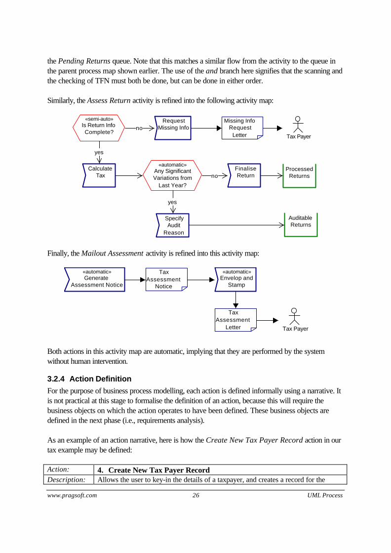
Similarly, the Assess Return activity is refined into the following activity map:
Is Return InfoComplete?
«semi-auto» RequestMissing Infono
CalculateTax
yes
Tax Payer
Any SignificantVariations from
Last Year?
«automatic»
yes
Missing InfoRequest
Letter
AuditableReturns
ProcessedReturnsno
FinaliseReturn
SpecifyAudit
Reason
Finally, the Mailout Assessment activity is refined into this activity map:
GenerateAssessment Notice
«automatic»Envelop and
Stamp
«automatic»TaxAssessment
Notice
TaxAssessment
Letter Tax Payer
Both actions in this activity map are automatic, implying that they are performed by the systemwithout human intervention.
3.2.4 Action DefinitionFor the purpose of business process modelling, each action is defined informally using a narrative. Itis not practical at this stage to formalise the definition of an action, because this will require thebusiness objects on which the action operates to have been defined. These business objects aredefined in the next phase (i.e., requirements analysis).
As an example of an action narrative, here is how the Create New Tax Payer Record action in ourtax example may be defined:
Action: 4. Create New Tax Payer RecordDescription: Allows the user to key-in the details of a taxpayer, and creates a record for the

UML Process 27 Copyright © 2005 PragSoft
taxpayer.Input: Details of a tax payer (TFN is optional)Output: Unique reference number for the record.
3.3 Use-Case ModellingAn alternative approach to producing a business model is to focus on the business functions ratherthan the business processes. This is essentially what has been popularised as the use-caseapproach.
Each use-case captures a way of using the system, that is, a business function. Because use-casesfocus on the functionality that the system will provide rather than the business processes that itshould support, the resulting system will be function centric. Consequently, this approach is suitablefor developing vertical applications, whereas business process modelling is better suited to enterpriseapplications.
To illustrate the difference between the two approaches, if we tried to model the Individual TaxReturn process described earlier using use-cases, we might come up with the following use-casemodel.
AssessReturn
Enter Details
Scan ReturnDocuments Lookup
Record
Create NewRecord
Link Recordand Docs
Calculate Tax
Finalise Return
Specify AuditReason
Request MissingInfo
Tax Return
Tax Clerk
Tax Payer
Mail Handler
The key differences with the process model are:
• The activities (Enter Details and Assess Return) become use-cases that refer to lower-leveluse-cases (which were actions in the process model).

www.pragsoft.com 28 UML Process
• Some of the actions (e.g., Scan Return Documents) become use-cases in their own right.
• There is no longer a clear notion of flow of control or conditions.
• If developed further, the use-case approach results in an application that does not convey orenforce a business process. The user is expected to know the process and to use the applicationto perform the steps that reflect his understanding of the process steps and their correctsequence.

UML Process 29 Copyright © 2005 PragSoft
4. Application ModellingAs stated earlier, application modelling is concerned with how systems support the business. Itproduces an external view of the solution, and does not assume any specific implementationtechnology.
In application modelling, we produce 3 types of models:
• Class diagrams , which depict the business objects underlying the business processes (or use-cases).
• Scenarios, which illustrate how business objects exchange messages in order to support theactions (or uses-cases).
• User interface models, which illustrate how the business functionality is presented to the user.
4.1 Business Objects1
Business processes (and business functions) involve business objects. Each business objectrepresents a major abstraction in the business domain that is characterised by data and behaviour.The data represents the persistent state of the object, and the behaviours represent what can bedone to the object, which in turn determines how the data is manipulated.
Given a business model (expressed as process maps or use-cases), we must analyse it to identify thebusiness objects. This is not a mechanical task and requires a good understanding of the businessdomain and a bit of creativity. For each object, we must identify:
• Its attributes (these represent the persistent data that record the object state).
• Its methods (these represent the behaviour of the object, i.e., the things that you can do to theobject).
• Its relationships to other objects (e.g., does this object make use of other objects?)
This results in a static model (called class diagram) that provides a lot of information about theobjects, without saying anything about how they work together in supporting the business processesor use-cases.
4.1.1 Class DiagramsThe UML notation is used for defining a class diagram, and includes the following symbols:
Customer A rectangle represents a class, where the name of the class(Customer here) appears inside the box.
1 The term object is somewhat misleading here; what we really mean is ‘business class’, because we are referringto an abstraction rather than an instance. Unfortunately, the IT literature tends to use the term ‘object’ to mean‘object’ and ‘class’; the exact intention being implied by the context.

www.pragsoft.com 30 UML Process
Customer
-name: String-dob: Date
-address: String
+Update(): Boolean+GetAccounts(): AccountList
Attributes and methods of a class may optionally be displayed insideit. Attributes appear immediately below the class name, separated by ahorizontal line from it. Methods appear beneath the attributes, againseparated by a horizontal line. The amount of information displayedcan vary. For example, we can display just an attribute name, or thename and its type. An attribute/method may have one of the followingsigns before it:• A minus (-) sign means that it is private.• A hash (#) sign means that it is protected.• A plus (+) sign means that it is public.
Jack:Customer A class instance uses the same symbol as a class, except that a colonprecedes the class name (and the colon may be optionally precededby the instance name). The resulting string is underlined to highlight thefact that it is an instance.
Billing This symbol represents a package. Packages are used to organisediagrams into logical hierarchies. For example, we may have a classdiagram that captures billing-related classes, another diagram thatcaptures accounts payable-related classes, and so on. Each of thesediagrams can be denoted by an appropriate package.
SavingAccount
Account A link with a hollow arrow-head denotes inheritance. Here, forexample, SavingAccount inherits from Account, which means thatSavingAccount inherits the attributes and methods of Account andmay additionally have its own attributes and methods. Account is ageneralisation and is referred to as a superclass. SavingAccount isa specialisation and is referred to as a subclass.
Account Statement A link with a solid diamond denotes composition. Here, for example,an Account is composed of (i.e., has) a Statement. This means thatStatement is an integral part of Account and cannot existindependently of it. Composition implies bi-directional navigation: youcan navigate from Account to Statement, and vice-versa.
Account Statement This is a variation of composition, called uni-composition. It impliesthat you can only navigate from Account to Statement, and not theother way round.
Account Transaction A link with a hollow diamond denotes aggregation. Here, forexample, an Account is an aggregation of (i.e., refers to) aTransaction. This means that Transaction can exist independently ofAccount. Aggregation implies bi-directional navigation: you cannavigate from Account to Transaction, and vice-versa.

UML Process 31 Copyright © 2005 PragSoft
TransactionAccount This is a variation of aggregation, called uni-aggregation. It impliesthat you can only navigate from Account to Transaction, and not theother way round.
Account Customer A plain link denotes an association. Here, for example, Account isassociated with Customer.
TellerServices
Products A dotted link with an arrow-head denotes dependency. Here, forexample, the Teller Services package is dependent on the Productspackage.
Account
Customer
n
1..2
Composition, aggregation, and association relationships may havecardinalities. These appear as labels near the end-points of the link.Here, for example, the cardinalities state that an Account is associatedwith one or two Customers, and a Customer may be associated withany number of Accounts.
Account
Customer
signatories
A relationship may also have specified roles for the objects to which itis connected. Here, for example, Customer(s) have the role ofsignatories in their relationship with Account.
Customer«business» A word enclosed in «» is called a stereotype . It provides a way of
extending the UML notation. Stereotypes may appear on classes,packages, and relationships. Here, for example, a «business»stereotype is used to distinguish Customer as a business class.
4.1.2 ExampleAn object analysis of our tax return process example might produce the following class diagram.

www.pragsoft.com 32 UML Process
TaxPayer
-TFN-name
-address-tel
-dob
+CalculateTax()+DoAudit()
+NewReturn()
TaxReturn
-grossEarning-deductions
-taxPaid-taxBalance
-taxYear-filingDate
+CalculateBalance()+GenerateAssessment()
TaxAudit
-auditDate-reason
-initiatedBy-status
+Update()
Document
-docID
+Print()
ScannedDoc GeneratedDoc
n
n
n
TaxAccount
-balance-interest
+GenerateStatement()+CreditDebit()
TaxStatementn
Document
n
TaxTransaction
-amount-date
-txnType-description
n
TaxSysn
This diagram states that the tax system (TaxSys class) is an aggregation of TaxPayers. EachTaxPayer has zero or more TaxReturns, and each TaxReturn has an associated set ofDocuments. A Document may be a ScannedDocument or a GeneratedDocument; furthermore, aTaxStatement is an example of a GeneratedDoc. For each TaxPayer a TaxAccount is heldwhich records the tax owed by/to the TaxPayer. This TaxAccount has TaxTransactions recordedagainst it. Also, TaxStatements may be generated against this account. Finally, a TaxPayer may besubjected to TaxAudits. Each such audit may have various associated Documents.
It is worth noting that not all the information captured by this class diagram comes directly from theprocess model. For example, additional questions need to be asked in order to identify the classattributes and their relationships. Also, TaxAccount, TaxTransaction, and TaxStatement are noteven referred to by the process model, but emerge out of further analysis of the problem domain. Insummary, to identify business objects, one should not be limited by the information provided by thebusiness processes; other useful sources of information should also be considered.
4.2 ScenariosHaving identified the business objects, we can now attempt to describe how each action (or use-case) is supported by these objects. These descriptions are called scenarios and can be expressedin two forms: as collaboration diagrams or as sequence diagrams.
4.2.1 Collaboration DiagramsA collaboration diagram describes a scenario as the exchange of messages between objects. Forexample, the CalculateTax action in our process example can be described by the followingcollaboration diagram.

UML Process 33 Copyright © 2005 PragSoft
:TaxSys :TaxPayer :TaxReturn
:TaxAccount :TaxTransaction
1. CalculateTax () 2. CalculateBalance ()
3. CreditDebit ()
4. Create()
Each message is depicted by a small arrow, emanating from the object that issues it, and directed tothe object that receives it. The receiving object must support the message (i.e., the message must beone that is exposed by the receiving object). The messages are numbered to depict their logicalsequence.
The above diagram, therefore, states that TaxSys issues a CalculateTax message to TaxPayer,which in turn issues a CalculateBalance message to TaxReturn. When the latter returns, TaxPayeruses the calculated tax balance to issue a CreditDebit message to TaxAccount, which in turnCreates a TaxTransaction object to record the credit/debit. Upon completion of these messages,control returns to TaxSys.
4.2.2 Sequence DiagramsA sequence diagram describes a scenario as the interaction among objects in time sequence. Forexample, the above collaboration diagram can be represented as the following sequence diagram.
:TaxSys :TaxPayer :TaxReturn :TaxAccount :TaxTransaction
CalculateTax ()
CalculateBalance ()
CreditDebit ()
Create()
The time sequence is denoted by the vertical line below each object. Time flow is downwards.

www.pragsoft.com 34 UML Process
4.2.3 Completed Business ModelWith the addition of business objects and scenarios, we now have a complete business model thatconsists of four layers, as illustrated below. Each lower layer contains a refinement for each of the‘abstractions’ in the layer above it.
Process
Activity
Action
Object
Bus
ines
s Fo
cuse
dA
pplic
atio
n Fo
cuse
d
and
The process layer defines the end-to-end business processes covered by the model. The activitylayer specifies each of the activities that comprise the business processes in the process layer. Theaction layer specifies each of the actions that comprise the activities in the activity layer. When anaction is performed, it affects one or more business objects (denoted by boxes in the third layer).

UML Process 35 Copyright © 2005 PragSoft
The object layer specifies the business objects that ultimately realise the business functionalitiesbehind the business processes.
4.3 User Interface ModelsTwo things make the user interface a crucial part of any business application:
• The user interface is the means by which the user is given access to the application’s businessfunctionality. Regardless of how sophisticated and comprehensive the underlying businessfunctionality might be, if the user interface is poor then all this will go to waste – the user willnever have the opportunity to benefit from it.
• Ultimately it is the user interface that shapes the way the user works. If the conceptual modelportrayed by the user interface is a close reflection of the user’s work practices, then it will bequickly understood and accepted by the user. On the other hand, if the conceptual model is socomplex, confused, or alien that the user finds it very difficult to relate to, it will put unnecessaryburden upon the user and reduce his/her productivity. In other words, the user interface shouldbe designed to match the user, not the other way round.
Common sense dictates that user interfaces should be designed based on the principle of recognitionrather than recollection. A successful user interface is one that draws upon the background andbusiness experience of its users to provide an intuitively obvious way of using it. A poor userinterface is one that requires extensive formal training and/or memorisation of an extensive list ofcommands and procedures.
4.3.1 MetaphorsSensible use of metaphors can make a user interface much more accessible to its target audience. Ametaphor is “a figure of speech in which an expression is used to refer to something that it does notliterally denote, in order to suggest a similarity”.
A user interface metaphor relies on a user’s familiarity with a common concept in order to suggesthow to do something unfamiliar. Graphical User Interfaces (GUIs) are full of such examples:
• Use of a ‘trash can’ as a means for deleting files.
• Use of ‘drag and drop’ as a means for moving objects around.
• Use of ‘desktop’ as a way of visualising and organising your work.
• Use of ‘directories’ as a way of organising files.
• Etc.
Before we go about designing a new user interface, we should spend some time exploring potentiallyuseful metaphors that can enhance the design. These should then influence the design.
4.3.2 Mock-upsThere are two ways to present a user interface design:

www.pragsoft.com 36 UML Process
• As static images (hand-drawn or created using a desktop tool), with associated prose thatdescribes the dynamic behaviour of the interface.
• As a live mock-up created using a visual development environment (e.g., VB or Java). The latter is always preferred, for two reasons. Firstly, people find it easier to relate to a mock-up.They can play with it and quickly come up with feedback about its good and bad aspects. Secondly,experience suggests that a good user interface is almost never created in one go. It often involvesmany iterations, during each of which the interface will undergo (sometimes major) changes. It isinvariably more productive and more effective to do these changes in a visual developmentenvironment. The creation of a mock-up should be guided by the following principles:
• The scope of the mock-up should be the business processes (or use-cases) that the applicationwill support. If someone suggests a screen or GUI element that cannot be directly or indirectlyjustified in terms of this scope, it should be excluded.
• The objective of the mock-up should be to show how a business process (or use-case) isperformed both in terms of the static information presented (i.e., screens) and the dynamic flowbetween the screens.
• Under no circumstances, a mock-up should be allowed to become anything more than a mock-up. There is always the risk of some users or business decision makers concluding that simplyenhancing or ‘finishing’ the mock-up will result in the final application. That is why that thepurpose of the mock-up should be clearly established and communicated up-front: to agree ona user interface design, and nothing more. The mock-up must be understood as a throw-awayartefact.
• Involving potential end-users in the design process can save a lot of time and energy. They notonly can come up with valuable insights and ideas that would have been inaccessible to thetechnologists, they can also become potential champions in introducing the user community tothe new application.

UML Process 37 Copyright © 2005 PragSoft
5. System ModellingAs stated earlier, system modelling is concerned with how systems are realised using technology.It produces an internal view of the solution, showing how its different parts interact in order tosupport the external, application view.
5.1 Multi-tier ArchitecturesModern information systems tend to be distributed: they use a multi-tier, client-server architecturethat can support the non-functional requirements of the system. These requirements often involve:
• Geographic distribution. Most large businesses are geographically distributed and require theirinformation systems to be accessible irrespective of geographic boundaries.
• Scalability. Once implemented, an information system may be required to serve the needs of agrowing user base. It should be possible to scale the system by increasing the computingresources, and without resorting to design changes.
• Heterogeneous computing environment. Most organisations have a multi-vendor computingenvironment, consisting of incompatible hardware and system software. An information systemmay be required to operate across the boundaries of such incompatible domains.
Distribution of an information system involves tiering, which divides the system into separatepartitions that can run on separate (but networked) physical resources. Tiering should not be confused with layering or, put differently, a software tier is not the same as asoftware layer. A software layer is a conceptual abstraction, which packages a defined set offunctionalities and makes it accessible through a logical interface. A software tier, on the other hand,is the physical packaging of the implementation of one or more software layers. Layering and tiering are the means through which an architect logically and physically partitions asystem, respectively. The software layers are defined during application modelling, whereas thesoftware tiers are established during system modelling. Layering affects tiering. By defining layers, anarchitect is providing opportunities for creating tiers. Early client-server systems were mainly two-tiered, consisting of a front-end and a back-end tier.Under this model, the front-end (also known as a fat client) contains the presentation as well as thebusiness logic, and the back-end consists of a database system. A two-tiered system is inflexible in anumber of ways:
• There is no logical separation between presentation and business logic, which makesmaintenance difficult.
• The system is not scalable.
• In most cases, the system lacks openness, because it is based on a vendor’s proprietarytechnology (e.g., database vendor’s technology).

www.pragsoft.com 38 UML Process
Modern client-server systems are mainly three-tiered, where the business logic is separated frompresentation and occupies its own middle tier. This approach provides a basis for overcoming theshortcomings of two-tiered systems.
Presentation &Business LogicPresentation &Business Logic
PresentationPresentation
Business LogicBusiness Logic
Data ServicesData ServicesData ServicesData Services
Two-tiered System Three-tiered System
Front-end Tier:
Middle Tier:
Back-end Tier:
The main challenge of building an effective three-tiered system is in designing and building the middletier. This tier needs to be designed in a way that delivers all the promised advantages of three-tieredsystems:
• It needs to remove the business logic from the front-end, so that the front-end only deals withpresentation concerns. This is known as the thin client approach.
• It needs to componentize the business logic in a way that can be distributed across hardwareresources so that it becomes scalable.
• It needs to provide open interfaces so that other systems can be integrated with it with minimaleffort.
The middle tier is often designed such that it can be subdivided into further tiers – hence the term n-tiered – to achieve greater scalability and to provide additional open interfaces. For example, it maybe broken into these three sub-tiers:
• A dynamic content tier that generates the content to be presented by the front-end.
• An application tier that realises the business processes offered by the system.
• A business object tier that realises the business objects underlying the system. Productive development of the middle tier requires the use of middleware technology, whichprovides the necessary tools for packaging the tiers, defining the interfaces between them,communication across the tiers, and transaction management. These are complex, system levelactivities that are well beyond the scope of a typical project. Middleware eliminates the need towork at this level, and provides a reliable basis for the project to focus on developing businessfunctionality.

UML Process 39 Copyright © 2005 PragSoft
Component technology goes a step further from middleware technology. It also provides a meansfor packaging functionality so that it is highly independent and reusable. Whereas middleware allowsone to develop business functionality without dealing with low-level system issues, componenttechnology aims to provide a basis for productively developing new functionality by reusing anexisting set of components (as well as creating new ones for future reuse). System modelling must deal with all these issues. Specifically, it must:
• Deliver a proper tiering model into which the software layers map.
• Define the abstractions (e.g., components) that comprise each tier, and show how they supportthe application model.
• Select the technologies that are to be used to build the system (e.g., middleware/ componenttechnology, persistence technology, presentation technology, scripting technology).
5.2 Front-End ModelsUnder the thin client architecture, the front-end deals with presentation only. Based on therequirements, the front-end may be designed according to one or more of the following models:
• Conventional client. This is a traditional style GUI client that involves intensive interactionbetween the user and the system (e.g., as in a spreadsheet, a word processor, or a CADsystem). These interfaces go beyond the simple input/output of data in most businessapplications, and require the lower-level controlling of the windowing system to deliver theexpected performance and ease of use. Although the client is not fat, it does not have a zerofootprint, as it needs to contain components that can support the interaction and communicatewith the middle tier.
• Page-based client. This is a browser-based client (i.e., runs within a HTML browser) with zerofootprint. The interface consists of a set of web pages, through which the user enters and/orviews data. A web server in the middle tier receives the data entered by the user, and generatesthe dynamic HTML to be displayed by the browser.
• Content-based client. This is also a browser-based client, but is implemented as a downloadedapplet that runs in the browser and communicates with a servlet in the middle tier’s web server.This is useful when we need to provide functionality directly at the front-end that helps a userorganise and interact with the system. In this case, the server exchanges raw content (typicallyexpressed in XML) with the client instead of HTML pages.
Because of their simplicity, flexibility, and web-readiness, more and more business applications areadopting the page-based and content-based styles. The key difference between these two is thepoint of control for presentation. With a page-based interface, the client receives preformattedpresentation (i.e., HTML) from the middle-tier, which it cannot alter. In this case therefore, themiddle-tier determines presentation. In a content-based client, however, the middle-tier delivers rawdata (i.e., content) to the client, and it is up to the client to determine how to display it. This is closerto the conventional client model.

www.pragsoft.com 40 UML Process
The following table provides a useful comparison of the three styles of clients. Your choice shouldbe guided by the extent to which a given style best matches your requirements. It is not uncommonfor a system to provide two or all of these styles for the same system, but targeted at different users.
Client Type PresentationDeterminedBy
Can DeliverDynamicContent
Is WebEnabled
RequiresClientInstallation
InteractionOverheads
Conventional Client Client No No Yes LowPage-based Client Middle-tier Yes Yes No HighContent-based Client Client Yes Yes Dynamic Medium
5.2.1 Screen SpecificationsBy the end of application modelling, the user interface concept (including mock ups) should havebeen established, so that once system modelling commences, the expected look and feel of the userinterface (and the underlying metaphors) is well understood.
Although the user interface concepts developed during application modelling include the actualscreens, they do not get into the details of each screen. The layout of each screen is rough and notfinalised, the widget types and the type of data to be displayed in each widget is not fully specified,and the data entry validation rules are excluded. These details are specified during system modelling.
Each screen in the user interface (e.g., a window, a dialog box, or a web page) needs to bespecified, including:
• A picture of the actual physical layout of the screen. If possible, this is best produced using thetools that come with the development environment. Most such environments are visual andprovide resource editors for painting the GUI screens in an interactive fashion. This has theadvantage that the screens can be used ‘as is’ later in the development cycle.
• For each element (i.e., widget) in the screen, the data associated with that element needs to beidentified and its type specified. In most cases, this data is expected to map directly to anattribute in a business object.
• The validation rules for the screen elements need to be defined. These apply at two levels: (i)field-level validation rules applicable to a given element (e.g., valid date), and (ii) screen-levelvalidation rules that operate across elements (e.g., ‘start date’ should predate ‘end date’).
5.2.2 NavigationThe navigation paths across user interface screens need to also be defined. In a conventionalinterface, for example, this may involve specifying how an action performed in one screen (e.g.,pressing a button) leads to the display of another screen. In a web-based interface, this will alsoinvolve the specification of the hyper links.

UML Process 41 Copyright © 2005 PragSoft
5.2.3 Boundary ObjectsUnder object technology, the user interface is developed as a collection of boundary objects. Aboundary object is a visual object that handles the interaction between the system and the end-user.
For example, consider the ‘Create New Tax Payer Record’ action in our tax office model. In thisaction, the user (a MailHandler) enters the details of the taxpayer into a form, which in turn createsa new TaxPayer object and adds it to the system. The following sequence diagram illustrates thisscenario.
Mail Handlerpayer:TaxPayer :TaxSys:TaxPayerForm
enter details
Create()
AddTaxPayer(payer)
TaxPayerForm is an example of a boundary object. It collects the required information from theuser and communicates it to the rest of the system.
In this case, it should be obvious that the contents of the form will closely resemble the attributes ofthe business object it corresponds to. The following design considerations are worth noting.
• Given that a change to a business object attribute will result in a similar change to the boundaryobject, a good design will attempt to minimise this overhead. Under the conventional clientmodel, there is not much that can be done. A browser-based client, however, can alleviate thisproblem by using an intermediate generator object that can take a meta-data specification of theobject and generate a matching boundary object for it.
• Field-level validation rules should be the responsibility of the boundary object. Simple field-levelvalidation rules (e.g., numeric value) can be directly encoded into the boundary object. Morecomplex field validation rules should be handled by invoking methods on objects that canperform the validation on behalf of the boundary object. Any form of validation that requiresdatabase access (e.g., valid postcode) is best handled by an object in the middle tier. Othercomplex filed validation rules (e.g., valid date) can be implemented by utility objects available inthe front-end and shared across the user interface.
• Screen-level validation rules should be the responsibility of the underlying business object. Forexample, when requested to create or modify a business object, the business object shouldperform the necessary validations to ensure that the resulting object will be valid.
In favour of better usability, more and more modern user interfaces incorporate dynamic behaviour.A typical example of this is when the value entered into a given form field affects the remaining fields,which may be enabled/disabled or displayed/hidden as a result. For example, in an account form,

www.pragsoft.com 42 UML Process
choosing a certain ‘account type’ may result in the rest of the form being altered so that onlyinformation relevant to that account type is displayed.
Also, there are cases where the relationship between a screen and the underlying business objects isone to many. For example, a ‘fund transfer’ screen typically involves two account objects, and an‘account summary’ screen may involve an account object and a list of transaction objects.
Dynamic screens and screens with one-to-many business object relationship are best supportedthrough proxy objects in the middle tier. Coding these complexities in the proxy object rather thanthe boundary object results in greater decoupling of the two tiers.
Finally, most modern interfaces are required to support pick lists. A pick list is a list of possiblevalues for a field, which the user can simply choose from, rather than entering the value directly. Picklists may be static or dynamic. A static pick list provides a list of values that remain forever fixed(e.g., a list of 12 months in the year). A dynamic pick list provides a list of values that change overtime (e.g., a list of available products). Static pick lists are simple enough to be coded directly intothe boundary object. Dynamic pick lists should be implemented in the middle tier and made availableto the front-end through appropriate interfaces.
5.3 Middle-Tier ModelsThe middle tier is by far the most complex part of any 3-tier client-server system. This is where thebulk of the development effort should go to ensure a resilient design that can best cope with futurechanges. The scalability of the system, in particular, is directly impacted by the design of the middletier.
The middle tier must achieve the following:
• Realise the business processes defined during business modelling.
• Release the business objects defined during application modelling.
• Implement transaction control (using the chosen middleware).
• Provide the services required by the front-end through a well-defined interface.
• Manage efficient communication with the back-end to ensure persistence for the relevantobjects.
• Partition the middle tier into components that can be distributed across physical resources withminimal overheads.
The middle tier is constructed using three types of objects: entity objects, control objects, andboundary objects. These are discussed below.
5.3.1 Entity ObjectsAn entity object is a persistent object that participates in transactions. The main entity objects in asystem are the business objects themselves. Ideally, the persistence of an entity object is managed

UML Process 43 Copyright © 2005 PragSoft
by the middleware. Where this is not the case, the entity object itself is responsible for issuing back-end requests to maintain its own persistence.
Each business object specified during application modelling is implemented as an entity object. Forexample, in our tax office model, TaxPayer, TaxReturn, and TaxAccount are all entity objects. Ifthese objects are specified fully during application modelling then their implementation as entityobjects is fairly straightforward. In practice, however, this is rarely the case. Often additionalanalysis is required to pin down the business rules for each such object, and to devise appropriatealgorithms for the non-trivial methods.
The implementation of an entity object should satisfy two things: (i) it should conform to the objectspecification, and (ii) it should preserve the relationships between the objects. For example, in ourtax office model, there is a one-to-many aggregation relationship between TaxPayer andTaxReturn. The methods of these objects must ensure that this relationship is not violated.
Another important implementation consideration is that, ideally, an entity object should make noassumptions about the underlying data representation for object persistence. This ensures thatchanges to the data model will not directly impact the entity objects.
It is worth noting that not all entity objects are business objects. For example, consider a‘workspace’ object that remembers the position of the windows for a given user and theirpreferences. This object needs to be persistent so that the next time the user logs in, his/herworkspace can be restored. Another example is an object that records transaction related statisticsfor audit or tuning purposes.
An important property of an entity object is that it is shared by all users, i.e., different users canengage in different transactions that potentially impact the same entity object. Of course, suchchanges cannot occur concurrently. It is the responsibility of the transaction management mechanismof the middleware to manage this.
From a design point of view, because entity objects are persistent (i.e., require database IO), theyconsume precious resources. The middle tier design, therefore, should try to exercise control overthe number of entity objects that need to be kept in memory at any point in time.
Most middle tier designs employ techniques such as smart pointers, object caching, and databaseconnection pooling to reduce the load on the resources.
5.3.2 Control ObjectsA control object sits between boundary and entity objects, and performs a task on behalf of theboundary object. In other words, a control object is an extension of a boundary object. Rather thanimplementing the task directly inside the boundary object (tight coupling), the task is implementedindependently (loose coupling). This provides enormous flexibility. Specifically:
• Changes to the boundary object will not necessarily impact the control object, and vice versa.

www.pragsoft.com 44 UML Process
• The control object can be remoted, so that it runs on a server, independently of the boundaryobject. This has the added advantage that the control object can be shared between a numberof clients.
Unlike entity objects, control objects are non-persistent, i.e., they do not need to maintain statebeyond the scope of the task they perform. However, some control objects may need to maintainstate for the length of the task (i.e., duration of conversation with a client). Based on this, controlobjects are divided into two categories:
• A stateful control object needs to maintain the state of some (or all of) its attributes for theduration of the conversation with its client. When the client finishes with the control object, thestate disappears. For example, a PolicyValue control object would need to remember thepolicy number attribute of the control object for the duration of the conversation.
• A stateless control object does not maintain a conversational state for a particular client. Whena client invokes the method of a stateless object, the object’s instance variables may contain astate, but only for the duration of the invocation. When the method is finished, the state is nolonger retained. For example, a CommissionPayment control object would require no state dueto its atomic nature.
Except during method invocation, all instances of a stateless control object are equivalent, and hencecan be assigned to any client. Because stateless control objects can support multiple clients andrequire no persistence, they can offer better performance and scalability for applications that requirelarge numbers of clients. As a rule of thumb, therefore, you should avoid using stateful controlobjects unless you really need to.
In general, each transaction is implemented in the middle-tier by a control object. The controlobject is itself responsible for transaction control (i.e., commit and rollback). In some cases, thisresponsibility may be abstracted by the middleware through deployment descriptors.
However, not all control objects implement transactions. A control object may also implement aquery. For example, a query to retrieve the last 20 transactions for a given account may be handledby a control object. This control object retrieves the account and the transactions (all entity objects)and makes them available to the client as required. This approach is particularly useful for queriesthat may return very large lists (e.g., retrieve all the transactions for a given account). Given thatentity objects are expensive, the control object can be implemented to do this smartly. For example,it may retrieve only a limited number of transactions at a time, and retrieve additional transactionsonly when the client needs them.
Proxy objects that support boundary objects in the front-end tier (as described in Section 5.2.3) arealso examples of control objects.
5.3.3 Boundary ObjectsThe interface between the middle-tier and the other tiers may involve boundary objects. Forexample, where the middle-tier is implemented as a CORBA server, the CORBA interface exposed

UML Process 45 Copyright © 2005 PragSoft
by the middle tier consists of boundary objects. Such boundary objects, however, are essentiallywrappers and provide no further functionality. They simply adapt a tier’s interface to a format that isagreed with another tier.
5.3.4 Long TransactionsThe implementation of transactions as control objects was discussed earlier. These transactions areknown as short transactions, i.e., they correspond to a task performed by a client at a specific time(e.g., transfer funds from one account to another).
There is another class of transactions, known as long transactions, which span beyond one task. Along transaction consists of a number of tasks, performed by potentially different users, and atdifferent points in time. For example, in a process-centric system, an end-to-end process (e.g.,home loan application) may be regarded as a long transaction.
Long transactions are generally very complex and pose a number of challenges:
• Two or more long transactions can overlap by operating on the same entity objects, with noguarantee that all will commit.
• Because a long transaction is performed in a piecemeal fashion, it has to cope with possiblymodified entity objects between its successive steps. Also, when the transaction is about tocommit, it needs to verify that interim modifications to the entity objects have not invalidatedearlier steps.
• Rolling back a long transaction may be a non-trivial task, because other transactions may nowbe relying on the modifications made by the transaction to entity objects.
• Unlike a short transaction, a long transaction needs to be implemented as a persistent object.The transaction may take hours, days, or even months to complete, during which time the usersparticipating in the transaction may login and out a number of times, and the system may berestarted.
These complexities go beyond virtually all middleware products’ transaction managementcapabilities. Also, effective management of a long transaction often requires access to relevantbusiness rules, which reside well beyond the middleware domain. As a result, when long transactionsare used, the middle-tier needs to implement its own long transaction management facility. Thisfacility needs to implement the following:
• Transaction persistence (i.e., realisation as an entity object).
• Versioning of entity objects. The entity objects modified by a long transaction need to beversioned to avoid the problem of overlapping transactions modifying the same entity object ininconsistent ways. Versioning can ensure that changes made by overlapped transactions aremutually excluded.
• Version reconciliation. If a transaction is performed on the basis of an old version of an entityobject, when committing, the transaction needs to reconcile itself against the latest version of theentity object.

www.pragsoft.com 46 UML Process
• Transaction rollback. With proper versioning of entity objects, this will be straightforward (i.e.,simply throw away the changes made by the transaction).
An unusual aspect of long transactions is that occasionally there may not be enough information toreconcile entity object versions at commit time. This will necessitate asking the user to make thedecision.
5.4 Back-End ModelsThe back-end tier of a three-tier client-server system is conceptually quite simple: it provides thepersistent storage for the entity objects of the middle tier. This tier provides two things:
• A data model for the storage of the objects.
• Adapter objects for accessing and updating the data.
5.4.1 Data ModelsFor a bespoke system, a new data model needs to be synthesized. The input to this process is theobject model created during application modelling and later enriched by system modelling. In mostcases, this is achieved by:
• Mapping each entity object to a table.
• Identifying appropriate keys for each table, based on the access paths required by objectmethods.
• Modelling the relationships between objects either using keys or additional tables. There arethree possible cases:
• A one-to-one relationship can be modelled using a key in either or both tables. Forexample, there is a one-to-one relationship between TaxPayer and TaxAccount, and thiscan be represented by having a TaxPayer key in the TaxAccount table, and/or vice versa.
• A one-to-many relationship can be modelled using a key in the ‘many’ table. For example,a one-to-many relationship between TaxPayer and TaxReturn can be represented byhaving a TaxPayer key in the TaxReturn table.
• A many-to-many relationship can be modelled using an additional table, which combinesthe keys for both tables. For example, a many-to-many relationship between Customer andAccount can be represented by a CustAccRel table that has attributes for recording thekeys of both tables.
Any non-trivial system, however, poses further data modelling challenges that need to be addressed.One of these involves the issue of inheritance and how to model it at a data level. There are no strictrules for handling inheritance, but the following two guidelines cover almost all cases:
• Where an inheriting object adds very few attributes to the inherited object, use the same table torepresent both. Obviously the table needs to include the attributes of both objects, and where anobject does not use a certain attribute, that attribute is simply ignored. For example,specialisations of an Account object (e.g., LoanAccount, SavingAccount, ChequeAccount)

UML Process 47 Copyright © 2005 PragSoft
are likely to add very few additional attributes. In this case, it makes sense to have one Accounttable to represent all account types. An additional attribute in the table can be used to denote theaccount type.
• Where the inheriting object adds many more attributes to the inherited object, use a separatetable for either, and include a key in the ‘inheriting’ table to refer to the ‘inherited’ object’s table.For example, a ContactPoint object may have specialisations such as PhysicalAddress,TelecomAddress, and WebAddress. These are fairly disjoint, so it makes sense to have a tablefor each.
The degree to which the data model needs to be normalised is a database design issue and shouldbe determined by the DBA. One of the advantages of OO modelling is that it tends to result in datamodels that are highly normalised.
The ER data model synthesized from the object model needs to be kept in sync with it. Processesneed to be put in place to ensure that developers work off a consistent set of object and datamodels. Experience has shown that this is an area where most projects encounter avoidableproblems.
Where legacy systems are involved (as is the case in most client-server projects), additionalconstraints are imposed. If all the data for the system is to be sourced from legacy systems, then thisrules out the possibility of developing a brand new and clean data model. Instead one has to adaptthe data provided to serve the needs of the middle-tier (and vice versa).
These constraints should be absorbed underneath the business object layer and should never beexposed beyond it. Any higher-level component that uses the business objects should not have to(or be allowed to) assume any knowledge about the underlying data model. This decouplingminimises the impact of a data model change on the rest of the system.
5.4.2 Data Access ObjectsDepending on the data model, there may or may not be a need to have an additional layer tomanage access to data. For example, in a bespoke system with a clean, new relational data model,the business objects may access this data through an open interface such as ODBC or JDBC. Noadditional processing is required.
However, where legacy systems are involved, there may be a need to perform additional processingto adapt the legacy data to the format required by the business objects. For example, a businessobject layer that talks XML is incompatible with a data layer consisting of CICS/COBOL legacysystems. This can be overcome by developing adapter objects that map the data between the formatused by the business objects and the format required by the legacy systems. These objects may alsoperform additional house keeping as relevant to the legacy systems involved.

www.pragsoft.com 48 UML Process
6. TestingThere are two philosophical views on the purpose of software testing:
• The purpose of software testing is to demonstrate that there are no defects.
• The purpose of software testing is to detect defects.
The problem with the first view is that it promotes the wrong psychology – it encourages the testersto come up with test cases that are likely to run successfully, rather than ones that break thesoftware.
The second view is based on the premise that any non-trivial application will always contain defects.The true value of testing is to detect as many defects as is economically feasible (and then to fixthem) in order to increase confidence in the reliability of the application.
6.1 IntroductionTesting should take place throughout the development lifecycle, so that defects are detected andfixed at the earliest opportunity. Most artefacts produced during the development lifecycle can betested if they are expressed in appropriate notations. For example, we can test a business processby passing hypothetical cases through it to check if there are any gaps in the flow or logic.
Extensive testing, however, cannot be undertaken until executable code has been produced.Because code is the ultimate artefact of software development, it should be subject to more testingthan other artefacts.
6.1.1 Testing ProcessThe underlying process for all forms of software testing is the same, and should adhere to thefollowing principles.
Before testing can begin, a test plan must be produced. The test plan defines a set of test cases, thecompletion criteria for the tests, and the environment required for performing the tests.
Each test case in a test plan consists of two things: test data and expected result. When a testcase is performed, the software is exercised using the test data and the actual result is comparedagainst the expected result. A match or discrepancy is then recorded in the test log. The test log is arecord of the test cases performed and their outcome.
A test plan must conform to a defined test strategy, which provides an overall framework for allthe different forms of testing for an application.
6.1.2 Testing ApproachesThere are two general approaches to testing: white box testing and black box testing.

UML Process 49 Copyright © 2005 PragSoft
In white box testing, test cases are formulated based on the internal design of the artefact beingtested. For example, if the artefact is the code for a class, then we can use the internal logic of theclass to create test cases that exercise all control flow paths through the code, so that everystatement is executed at least once.
In black box testing, the artefact being tested is treated as a black box that, given a set of inputs,produces some output. This means that no knowledge of the internal design of the artefact isassumed. Test cases are created based on the range of the input values that the artefact shouldaccept (or reject) and their relationships to the expected output values.
White box testing is more applicable to lower-level artefact, such as functions, classes, andcomponents. Black box testing is better suited to higher-level artefacts, such as application modules,applications, and integrated systems. Given that white box and black box testing tend to exposedifferent types of defects, it is generally recommended that a combination of the two be used in thedevelopment lifecycle in order to maximise the effectiveness of testing.
6.1.3 Testing TechniquesA number of different testing techniques have been devised for use at various stages of development.On its own, no one technique is sufficient to produce adequate test cases. The techniques, rather,serve as a toolbox that test designers can utilise to design effective test cases. The most widelyrecognised techniques are:
• Coverage testing. This is a white box technique that attempts to achieve a certain level of codecoverage. Typical types of coverage considered are:
• Statement coverage requires that enough test cases be created to exercise every statementin code at least once.
• Branch coverage requires that all the alternatives of every decision branch in the code beexercised at least once.
• Condition coverage requires the true/false outcome of every condition in the code isexercised at least once. This is not the same as branch coverage, since the logical expressionfor a branch may, for example, be a conjunction of multiple conditions.
• Boundary value testing. This is a black box testing technique, where test cases are writtensuch that they involve input or output values that are around the boundary of their permissiblerange. For example, if a function takes a ‘day of month’ argument then values such as -1, 0, 1,30, 31, 32 are around the boundary of permissible values and would be good input test data.
• Cause effect graphing. This is a white box technique that involves mapping out the logicalrelationships between causes (input values representing a meaningful condition) and effects(output values representing a corresponding meaningful outcome). An example of a cause mightbe a ‘positive amount in a transaction’ and its corresponding effect may be ‘an account beingcredited’. Once all the possible causes and effects have been listed, then test cases are designedsuch that each cause and all its potential effects (and each effect and its potential causes) areexercised at least once.

www.pragsoft.com 50 UML Process
• Domain analysis. This is a black box technique that involves analysing the domain of eachinput value, and subdividing it into sub-domains, where each sub-domain involves ‘similarvalues’ in the sense that if you use one of these values in a test-case, it will be as good as anyother value in that sub-domain. For example, the domain of an ‘amount’ input value might besubdivided into the ranges 0-1000, 1001-100,000, and >100,000; these three sub-domainsbeing different from an authorisation point of view. Based on the outcome of domain analysis, aminimum number of test cases can be designed that will have a high yield, by avoiding the use of‘similar’ values in separate test cases.
• Error guessing. Error guessing involves using your imagination to come up with test cases thatare likely to break the artefact being tested. There are no particular rules in this technique,except that the more unusual and nonsensical the test-cases, the more likely is their effectiveness.
One point that is often overlooked by test case designers is the use of erroneous input data. It isimportant that testing should involve at least as many invalid or unexpected input values as valid orexpected ones. Once an application goes live, it will be used in ways that go beyond the originalexpectations of its designers. It is important that the application behaves gracefully in face of invalidor unexpected input data.
6.1.4 Testing StagesDuring its development lifecycle, software is subjected to testing at a number of stages, assummarised by the following table.
Stage Type of Testing By Who PurposeAfter a ‘unit’ has beencoded.
Unit Testing Developers To detect any variances betweenthe ‘unit’ behaviour and itsspecification.
When a number of unitsare combined to create anexecutable module (e.g., atier in a distributedapplication).
Integration Testing Developers To detect any discrepancies in theinterfaces between the units (e.g.,mismatching message formatbetween two components).
When the modules arecombined to create anintegrated application (e.g.,all the tiers in a client-server application).
Integration Testing Developers To detect any discrepancies in themodules that makes up theapplication (e.g., a client expectinga server to send a single record inresponse to a request, whereas itactually sends a list of records).
When an integratedapplication is robust enoughto undergo extensive testing(e.g., after all cross-tiermismatches have beenfixed).
System Testing Test Team To detect any variances betweenthe way the application behaves andits official requirements model (e.g.,a request should take < 5 seconds,whereas in practice it takes 30seconds to complete).
When an application isrequired to inter-operate
Integration Testing Test Team To detect any discrepancies in theinterfaces between applications

UML Process 51 Copyright © 2005 PragSoft
with other applications in anenterprise solution.
(e.g., a change of employee addressis reflected in the company Intranet,but not in the payroll application).
When a solution isdelivered to its intendedcustomer.
Acceptance Testing Customer This is the only type of testingperformed by the customer. It givesthe customer the opportunity toverify the fit of the application withrespect to their requirements,before officially accepting theapplication.
As indicated by this table, integration testing comes in various forms and happens at a number ofstages. Unfortunately, most publications on testing refer to integration testing as if it only happensonce in the development lifecycle, and this has led to much confusion. The confusion can be avoidedby bearing in mind that integration testing should happen whenever a number of artefacts of similarcharacteristics are combined, be they classes, components, modules, application tiers, or entireapplications.
System testing is by far the most labour intensive testing stage, because there are so many differenttypes of tests that need to be performed. Because of the specialised nature of system testing, it mustbe performed by a dedicated test team that specialises in this area. In particular, it should never bedone by the developers themselves, since they neither have the required expertise, nor theappropriate psychological profile to do it effectively.
In most projects, the customer relies on the developers to help them with creating an acceptance testplan. Because of the extensive nature of system testing, virtually everything that needs to be verifiedin acceptance testing is likely to have been tested for in system testing. As a result, acceptancetesting often involves a subset of the test cases used for system testing.
6.1.5 Regression TestingWith any type or stage of testing, one has to deal with the problem of tested artefacts beingmodified. The dilemma is that, on the one hand, we are aware that the modifications may well haveintroduced new defects and, on the other hand, we do not want to incur the overhead of completelyretesting the artefact every time we make changes to it.
The aim of regression testing is to check if the modifications have caused the artefact to regress (i.e.,have introduced new defects into it). It should be obvious that unless regression testing can be donequickly, the whole development cycle grinds to a halt. There are two ways of regression testingproductively:
• By selecting a high yield subset of the original tests and only running these.
• By using appropriate testing tools to automate the testing process, so that they can be performedwith minimal human intervention.

www.pragsoft.com 52 UML Process
The latter is much more effective, but does involve a greater upfront investment in creating the testscripts required by the automated testing tools.
6.2 Test PlanningSuccessful testing requires appropriate planning. Given that test planning requires substantial amountof effort and a considerable length of time, the actual planning must begin well before the artefacts tobe tested are ready for testing.
Test planning covers four key activities:
• The creation of a test strategy that will guide all testing activities.
• The creation of test plans for the different stages of testing.
• The setting up of the test environment so that the test plan can be carried out.
• The creation of test scripts for automated testing.
These are separately discussed below.
6.2.1 Test StrategyThe test strategy provides an overall framework for all testing activities in a project (or group ofrelated projects). This may sound motherhood and unnecessary but, in practice, it can have asignificant impact on the way testing is carried out.
The primary objectives of a test strategy are to:
• Ensure a consistent approach to testing at all stages.
• Spell out the things that are crucial to the project as far as testing is concerned (e.g., iterationspeed, robustness, completeness).
• Provide guidelines on the relevant testing techniques and tools to be used.
• Provide guidelines on test completion criteria (i.e., define what is ‘good enough testing’), and theexpected amount of effort that should go into testing.
• Provide a basis for reusing test cases and identifying areas that can benefit from automation.
• Establish standards, templates, and the deliverables that need to be used/produced duringtesting.
6.2.2 Test PlanA test plan is a documentation of the test cases to be performed and associated instructions forperforming the tests. Two levels of test plans are often used:
• A master test plan is used to identify the high-level objectives and test focus areas.
• A detailed test plan is used to document the test cases produced as a result of analysing thetest focus areas identified in the master test plan.
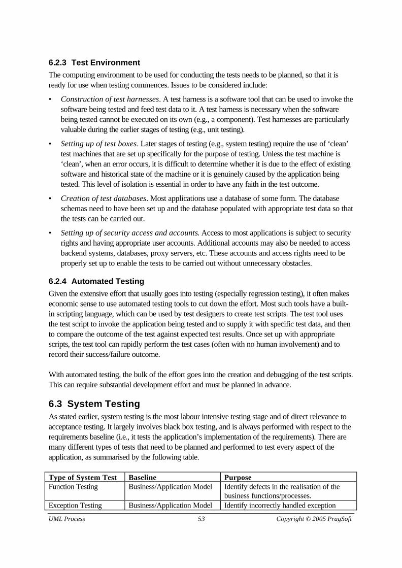
UML Process 53 Copyright © 2005 PragSoft
6.2.3 Test EnvironmentThe computing environment to be used for conducting the tests needs to be planned, so that it isready for use when testing commences. Issues to be considered include:
• Construction of test harnesses. A test harness is a software tool that can be used to invoke thesoftware being tested and feed test data to it. A test harness is necessary when the softwarebeing tested cannot be executed on its own (e.g., a component). Test harnesses are particularlyvaluable during the earlier stages of testing (e.g., unit testing).
• Setting up of test boxes. Later stages of testing (e.g., system testing) require the use of ‘clean’test machines that are set up specifically for the purpose of testing. Unless the test machine is‘clean’, when an error occurs, it is difficult to determine whether it is due to the effect of existingsoftware and historical state of the machine or it is genuinely caused by the application beingtested. This level of isolation is essential in order to have any faith in the test outcome.
• Creation of test databases. Most applications use a database of some form. The databaseschemas need to have been set up and the database populated with appropriate test data so thatthe tests can be carried out.
• Setting up of security access and accounts. Access to most applications is subject to securityrights and having appropriate user accounts. Additional accounts may also be needed to accessbackend systems, databases, proxy servers, etc. These accounts and access rights need to beproperly set up to enable the tests to be carried out without unnecessary obstacles.
6.2.4 Automated TestingGiven the extensive effort that usually goes into testing (especially regression testing), it often makeseconomic sense to use automated testing tools to cut down the effort. Most such tools have a built-in scripting language, which can be used by test designers to create test scripts. The test tool usesthe test script to invoke the application being tested and to supply it with specific test data, and thento compare the outcome of the test against expected test results. Once set up with appropriatescripts, the test tool can rapidly perform the test cases (often with no human involvement) and torecord their success/failure outcome.
With automated testing, the bulk of the effort goes into the creation and debugging of the test scripts.This can require substantial development effort and must be planned in advance.
6.3 System TestingAs stated earlier, system testing is the most labour intensive testing stage and of direct relevance toacceptance testing. It largely involves black box testing, and is always performed with respect to therequirements baseline (i.e., it tests the application’s implementation of the requirements). There aremany different types of tests that need to be planned and performed to test every aspect of theapplication, as summarised by the following table.
Type of System Test Baseline PurposeFunction Testing Business/Application Model Identify defects in the realisation of the
business functions/processes.Exception Testing Business/Application Model Identify incorrectly handled exception

www.pragsoft.com 54 UML Process
situations.Stress Testing Non-functional Requirements Identify stress levels beyond which the
application cannot operate.Volume Testing Non-functional Requirements Identify data volume levels beyond which
the application cannot operate.Scalability Testing Non-functional Requirements Identify the limit beyond which the
application will not scale.Availability Testing Non-functional Requirements Measure the availability of the application
over a prolonged period of time.Usability Testing Business/Application Model
Non-functional RequirementsIdentify problems that reduce theapplication’s ease of use.
Documentation Testing Business/Application ModelNon-functional Requirements
Identify problems in the userdocumentation for the application.
Installation Testing System Model Identify problems in the installation processfor the application.
Migration Testing System Model Identify problems in the migration of datafrom the legacy system to the application.
Coexistence Testing System Model Identify problems caused by thecoexistence of the application with otherapplications in the same live environment.
Each of system tests is separately described below.
6.3.1 Function TestingThe purpose of function testing is to identify defects in the ‘business functions’ that the applicationprovides, as specified by the business/application model. If this model is specified as businessprocesses (as recommended earlier in this handbook), then the test cases are built around thesebusiness processes. If it is specified as use-cases, then the test cases are built around the use-cases.
6.3.2 Exception TestingAn exception refers to a situation outside the normal operation of an application (as represented, forexample, by invalid input data or incorrect sequence of operations). For example, a mortgageapplication may require that before a mortgage account can be created, the mortgagee record musthave been created. Therefore, an attempt to create a mortgage account when the mortgagee isunknown to the system is an example of an exception.
Exception testing is, in a way, the opposite of function testing – it tests for dysfunctional behaviour. Ifan application successfully passes function testing, then it is not necessarily fit for business. It may bethe case that it does allow dysfunctional operations to be performed, which, from a business point ofview, can lead to liability or financial loss. The purpose of exception testing is to identify exceptionsituations that are not satisfactorily handled by the application.
6.3.3 Stress TestingStress testing involves observing the behaviour of the application under ‘stress conditions’. Exactlywhat these conditions are depends on the nature of the application. For example, in a web-based

UML Process 55 Copyright © 2005 PragSoft
financial application, a very large number of transactions and a very large number of end-userswould represent stress conditions. ‘Large’ in this context should be interpreted as ‘equal to, greaterthan, and much greater than’ what has been specified in the non-functional requirements. If therequirements call for the support of up to 500 concurrent users, then we should, for example, testfor 500, 600, 1000, etc.
The purpose of stress testing is to identify the stress conditions that cause the application to break. Ifthese conditions are within the expected operational range of the application, then we conclude thatthe application has failed the stress tests.
Stress conditions can and do arise when the application goes live. It is therefore important to knowwhat the stress limits of the application are, so that contingency plans can be made.
6.3.4 Volume TestingVolume testing involves observing the behaviour of the application when it is subjected to very largevolumes of data. For example, if the application is a banking system having an underlying databasefor storing account records, volume testing will attempt to populate this database with maximumcapacity records and beyond. For example, if the requirement is for the system to store up to amillion accounts, then we may try to populate the database with 1 million, 2 million, and 5 millionrecords.
The purpose of volume testing is to identify the volume levels beyond which the application will beunable to operate properly (e.g., physical storage limit or acceptable performance level).
As with stress testing, unanticipated volume levels can occur when the application goes live, and it istherefore important to know the volume limits for contingency reasons.
6.3.5 Scalability TestingMost modern business applications are multi-user, distributed, client-server systems that serve alarge user base. The ‘growth’ (i.e., increased use) of an application in a business is often difficult topredict. Some applications that are originally designed for a handful of users, later end up being usedby hundreds or thousands of users. The ability of an application to serve a growing user base (andgrowing transaction volume) should therefore be an important consideration.
The degree to which the use of an application can grow without making any design changes is calledscalability. A scalable architecture can ensure that the application can grow by simply adding morehardware resources to distribute the application across more and more boxes.
The purpose of scalability testing is to identify the boundaries beyond which the application will notbe able to grow. Scalability testing is environmentally complex because it involves making changes tothe distribution model of the application for its test cases.
There is an obvious interplay between scalability and stress/volume testing, and this needs to betaken into account when test planning.

www.pragsoft.com 56 UML Process
6.3.6 Availability TestingEach application has certain availability requirements, as determined by the business environmentwithin which it runs. This is often expressed as a percentage for a given duration (e.g., 98%availability for the month of July).
The purpose of availability testing is to determine if the application availability falls below theminimum acceptable level. This is measured by running the application over a long duration (e.g., aweek, a month, or until it falls over) while it is subjected to a realistic load.
6.3.7 Usability TestingThe purpose of usability testing is to identify any features or obstacles in the design of the application(mainly its user interface) that makes the application difficult to use. Although usability is a subjectivenotion, there are meaningful measures that can be employed to establish the relative usability of anapplication. For example, given a certain level of initial training, users can be observed with thepurpose of recording measures such as:
• The average length of time needed to complete a business process/activity/action.
• The number of errors made during a business process/activity/action.
• The amount of time spent on rework due to errors.
• Given a certain task, the length of time it takes a user to find out how to use the application to doit.
6.3.8 Documentation TestingThe purpose of documentation testing is to establish the relevance, usefulness, readability, andaccuracy of end-user documentation for the application. This is performed using just the supplieddocumentation in order to operate the application. So for each given test case, the tester will refer tothe documentation to find out the instructions for performing it. In other words, the testing processwill simulate the actions of an untrained user who has to use the application on basis of theinformation provided.
Documentation testing will detect defects in the user documentation, such as: gaps (no explanation ofhow to do a certain task), factual errors, ambiguity, technical jargon, and out of date information.
6.3.9 Installation TestingThe purpose of installation testing is to detect defects in the installation process for the application.Modern applications are supplied with installation tools/scripts that automate the installation process.Installation test cases involve attempting to install the application (in a clean environment) using theinstallation package provided (i.e., installation scripts, documentation, and release notes).
6.3.10 Migration TestingMost modern applications are replacements for legacy systems. For business continuity, often thelegacy data needs to be preserved and migrated to the new application. This is usually a very

UML Process 57 Copyright © 2005 PragSoft
complex problem that is addressed through development: the creation of the necessary tools/scriptsto migrate the data is part of the same project.
The purpose of migration testing is to identify defects in the data migration process. Migration testcases involve attempts to migrate the legacy data to a clean installation of the application.
6.3.11 Coexistence TestingIn a live environment, most applications run in conjunction with other applications. The system testenvironment, however, is usually isolated and not as complex as the live environment. Potentialinterplay between applications (that compete for resources and interact with each other) cannot beruled out in a live environment. The purpose of coexistence testing is to establish whether theapplication can successfully coexist with other applications.
Coexistence testing is usually carried out first in a pseudo live environment, and then in the liveenvironment itself, but with restricted access.
6.4 Test Case DesignThe design of test cases is, by far, the most important part of testing, since it is the quality of the testcases that determines the overall effectiveness of testing.
The layered architecture reference model (see Section 2.3.2) provides a sound basis for organisingthe design of test cases. Using this model, each layer is considered separately, in order to design testcases that cover that layer. This results in the test case design effort being divided into 4 categories,as summarised by the following table:
Architecture Layer Test Case Design Effort CategoryPresentation Presentation oriented test case designWorkflow Workflow oriented test case designBusiness Object Business object oriented test case designData Services Data oriented test case design
This logical separation ensures that every important architectural consideration is fully tested. It doesnot, however, provide complete coverage for all system test types. Additional test cases need to becreated for these, especially those that involve non-functional requirements.
All 4 categories use the same source material for designing the test cases, which consists of thefollowing:
• Business model. This is probably the most important source, as it describes the businessactivities that the application supports.
• Application model. This is also important in that it provides a picture of what the application issupposed to do, and can compensate for gaps in the user documentation.
• System model. This is important as a formal and detailed technical source, and is especiallyuseful in relation to non-functional requirements.

www.pragsoft.com 58 UML Process
• Non-functional requirements. This covers the important constraints that the application shouldsatisfy (e.g., performance requirements).
• User documentation concept. It is unlikely that by the time system testing commences, theuser documentation would be ready. However, it is reasonable to expect that by then conceptdocuments be at least produced, providing a terse version of the intended documentation.
We will look at each category in turn, and provide a table for showing how the source materialrelates to each major test focus area, and to which system test type the resulting test cases belong.
6.4.1 Presentation Oriented Test Case DesignThese tests are concerned with all those aspects of the application that are manifested through theuser interface. Major test focus areas are:
• Presentation layout, which uses the actual design of the user interface to design test cases thatassess the ease of comprehension of the presentation.
• Input data validation, which uses the specification of the validation rules for input data todesign test cases that assess the correctness of the implementation of these rules.
• Interaction dynamics, which uses the rules for dynamic feedback to the user (e.g.,enabling/disabling of GUI elements) to design test cases that assess the correctness of theimplementation of these rules.
• Navigation, which uses the specification of navigation paths from one window to another todesign test cases that assess the correctness of the implementation of these paths.
• Productivity, which considers things that can affect user productivity (e.g., response time, easeof use, rework frequency) to design test cases that can identify barriers to user productivity.
• Documentation, which uses the user documentation concept to design test cases that canidentify potential problems in the user interface documentation.
MAJORTEST FOCUSAREA
SOURCE MATERIAL FOR TEST CASE DESIGN INCLUDE INSYSTEMTEST TYPE
BusinessModel
ApplicationModel
SystemModel
Non-fun’lRequirem’ts
User DocoConcept
Presentation Layout × × Usability TestingInput Data Validation × Exception TestingInteraction Dynamics × Usability TestingNavigation × × Usability TestingProductivity × × × Usability TestingDocumentation × Doco. Testing
The above table summarises the major test focus areas for presentation oriented test case design.For each focus area, the source materials to be used for test case design and the system test typesunder which the test cases are to be documented are identified.

UML Process 59 Copyright © 2005 PragSoft
6.4.2 Workflow Oriented Test Case DesignThese tests are concerned with the instantiation and execution of business processes. Major testfocus areas are:
• Workflow Logic, which uses process/activity maps to design test cases that exercise the variouspaths through the process.
• Workflow Data, which involves test cases that will handle the specific data items (e.g.,documents) created/manipulated by the process.
• Security, which involves test cases that ensure that those aspects of a business process thathave restricted access are only available to users with the relevant security rights.
• Workflow Validation, which involves test cases that attempt to invoke exception situations forthe process to see how they get handled.
• Documentation, which involves test cases that attempt to perform a process, based on itsdocumentation.
MAJORTEST FOCUSAREA
SOURCE MATERIAL FOR TEST CASE DESIGN INCLUDE INSYSTEMTEST TYPE
BusinessModel
ApplicationModel
SystemModel
Non-fun’lRequirem’ts
User DocoConcept
Workflow Logic × Function TestingWorkflow Data × × Function TestingSecurity × Function TestingWorkflow Validation × Exception TestingDocumentation × Doco. Testing
6.4.3 Business Object Oriented Test Case DesignThese tests are concerned with the instantiation and manipulation of business objects. Major testfocus areas are:
• Object Behaviour, which uses the business object models to design test cases that exercise themethods of each business object.
• Object Validation, which involves test cases that attempt to create invalid business objects.
MAJORTEST FOCUSAREA
SOURCE MATERIAL FOR TEST CASE DESIGN INCLUDE INSYSTEMTEST TYPE
BusinessModel
ApplicationModel
SystemModel
Non-fun’lRequirem’ts
User DocoConcept
Object Behaviour × Function TestingObject Validation × × Exception Testing
6.4.4 Data Oriented Test Case DesignThese tests are concerned with the storage and retrieval of persistent objects. Major test focus areasare:

www.pragsoft.com 60 UML Process
• Object Persistence, which involves test cases that verify the correct persistence of entityobjects.
• Persistence Efficiency, which involves test cases that measure the time required tostore/retrieve persistent objects.
• Storage Capacity, which involves test cases that attempt to exercise the storage limits of theapplication.
• Backup & Recovery, which involves test cases for backing up the application database andthen restoring it from the backup image.
MAJORTEST FOCUSAREA
SOURCE MATERIAL FOR TEST CASE DESIGN INCLUDE INSYSTEMTEST TYPE
BusinessModel
ApplicationModel
SystemModel
Non-fun’lRequirem’ts
User DocoConcept
Object Persistence × Function TestingPersistence Efficiency × × Usability TestingStorage Capacity × Volume TestingBackup & Recovery × × Availability Testing