uml: unified modeling language
DESCRIPTION
UML: Unified Modeling Language. V22.0474-001 Software Engineering Lecture 5, Spring 2006 Clark Barrett, New York University. Modeling. Describing a system at a high level of abstraction A model of the system Used for requirements and specification Many notations over time State machines - PowerPoint PPT PresentationTRANSCRIPT
Adapted from CS 169, George Necula, Berkeley 1
UML: Unified Modeling Language
V22.0474-001 Software Engineering
Lecture 5, Spring 2006
Clark Barrett, New York University

2
Modeling
• Describing a system at a high level of abstraction– A model of the system– Used for requirements and specification
• Many notations over time– State machines– Entity-relationship diagrams– Dataflow diagrams

3
Recent History: 1980’s
• The rise of object-oriented programming
• New class of OO modeling languages
• By early ’90’s, over 50 OO modeling languages
4
Recent History: 1990’s
• Three leading OO notations decide to combine– Grady Booch (BOOCH)– Jim Rumbaugh (OML: Object Modeling
Technique)– Ivar Jacobsen (OOSE: OO Soft. Eng)
• Why?– Natural evolution towards each other– Effort to set an industry standard

5
UML
• UML stands forUnified Modeling Language
• Design by committee– Many interest groups participating– Everyone wants their favorite approach to be
“in”

6
UML (Cont.)
• Resulting design is huge– Many features– Many loosely unrelated styles under one roof
• Could also be calledUnion of all Modeling Languages

7
This Lecture
• We discuss– Use Case Diagrams for functional models– Class Diagrams for structural models– Sequence Diagrams– Activity Diagrams for dynamic models– State Diagrams
• This is a subset of UML– But probably the most used subset

8
Sources and more information
• Practical UML: A Hands-On Introduction for Developers – by Randy Miller– http://bdn.borland.com/article/0,1410,31863,00.html
• UML 2 for Dummies – by Chonoles and Schardt– Available on books24x7 through home.nyu.edu
• CS 169 web page (George Necula, Berkeley)– http://www-inst.eecs.berkeley.edu/~cs169/fa04/lectures.shtml
• Free UML tool– ArgoUML: http://argouml.tigris.org

9
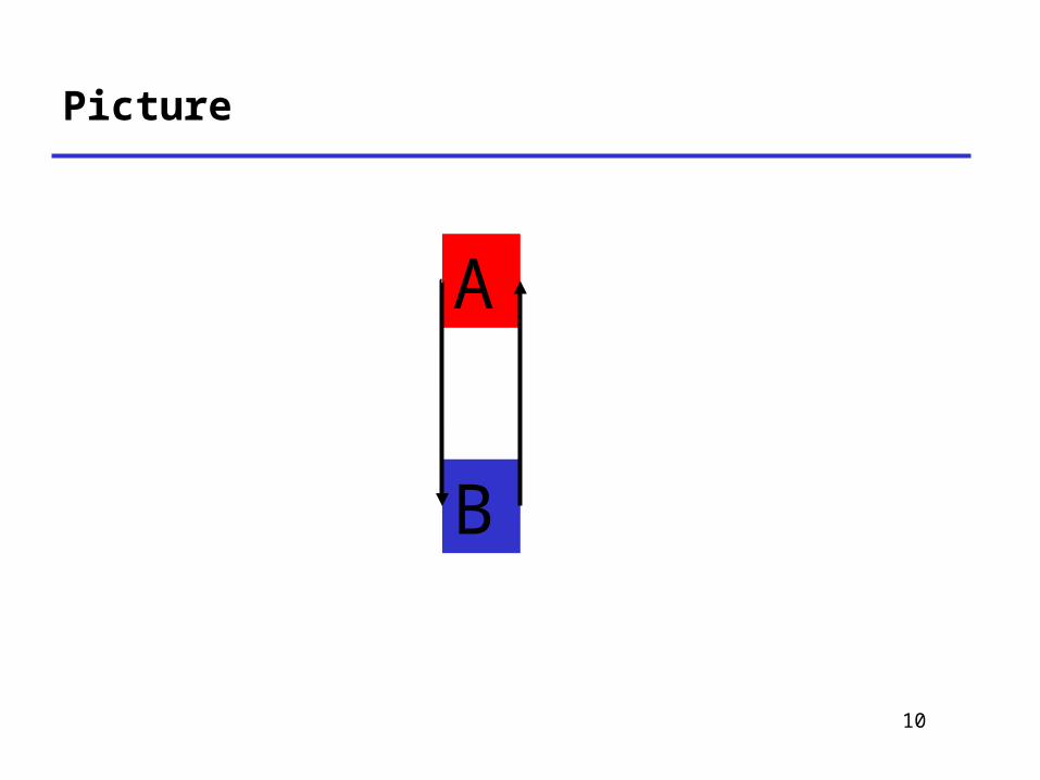
Running Example: Automatic Train
• Consider an unmanned people-mover– as in many airports
• Train – Moves on a circular track– Visits each of two stations (A and B) in turn– Each station has a “request” button
• To stop at this station
– Each train has two “request” buttons• To stop at a particular station
10
Picture
A
B

11
Use-Cases
• Describe functionality from the user’s perspective
• One (or more) use-cases per kind of user– May be many kinds in a complex system
• Use-cases capture requirements

12
An Example Use-Case in UML
• Name– Normal Train Ride
• Actors– Passenger
• Entry Condition– Passenger at station
• Exit Condition– Passenger leaves station

13
An Example Use-Case in UML
• Event-flow– Passenger presses request button– Train arrives and stops at platform– Doors open– Passenger steps into train– Doors close– Passenger presses request button for final stop– …– Doors open at final stop– Passenger exits train
• Nonfunctional requirements

14
Use Case Diagram
• Graph showing– Actors– Use cases– Edges actor-case if that
actor is involved in that case
• Actors– Stick figures
• Use cases– Ovals
Repair
Ride
passenger
technician
15
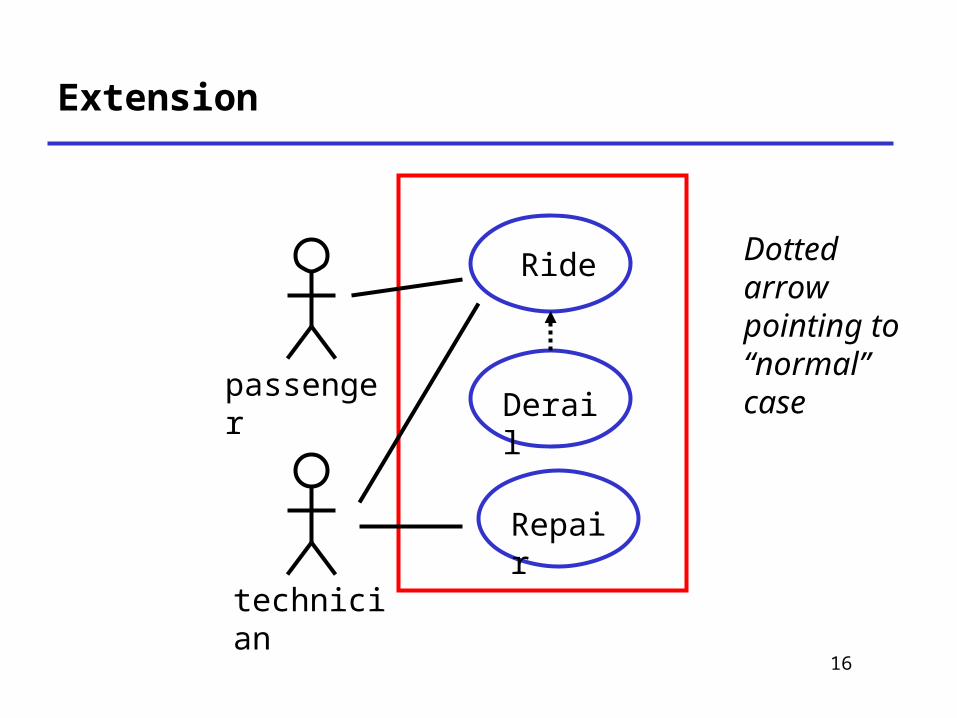
Exceptional Situations
• Use cases have relationships– Inclusion (E.g., push button included in ride)– Variations
• UML has a special notation– The “extends” relationship to express a
exceptional variation of a use case– Normally used to express errors
16
Extension
Repair
Ride
passenger
technician
Derail
Dotted arrow pointing to “normal” case
17
Summary of Use Cases
• Use Case Diagram– Shows all actors, use cases, relationships– Actors are agents external to the system
• E.g., users
• Supplemental information– Entry/Exit Conditions, Story, Main and
Alternative flows, Nonfunctional requirements– Specified in a separate document
• In English
18
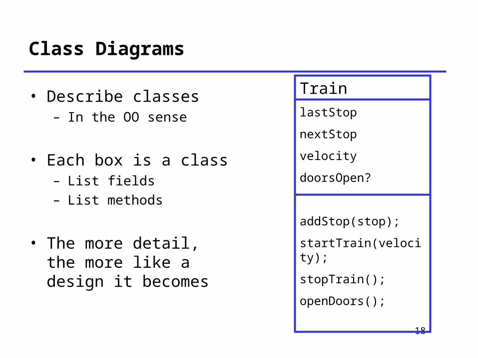
Class Diagrams
• Describe classes– In the OO sense
• Each box is a class– List fields– List methods
• The more detail, the more like a design it becomes
TrainlastStop
nextStop
velocity
doorsOpen?
addStop(stop);
startTrain(velocity);
stopTrain();
openDoors();

19
Class Diagrams: Relationships
• Many different kinds of edges to show different relationships between classes
• Mention just a couple

20
Associations
• Capture n-m relationships– Subsumes ER diagrams
• Label endpoints of edge with cardinalities– Use * for arbitrary
• Typically realized with embedded references
• Can be directional (use arrows in that case)
Station
RequestButton
1
1
One request button per station; each train has two request buttons
Train
2
1
21
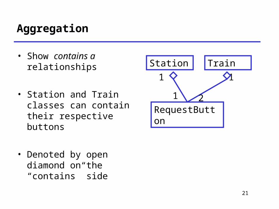
Aggregation
• Show contains a relationships
• Station and Train classes can contain their respective buttons
• Denoted by open diamond on the “contains” side
Station
RequestButton
1
1
Train
2
1

22
Generalization
• Inheritance between classes
• Denoted by open triangle
Button
RequestButton
EmergencyButton

23
More about Class Diagrams
• Classes vs Objects– Same diagrams can be used to specify
relationships between instances of classes
• Roles and Association Classes– More detail on relationships between classes
• Hierarchical Diagrams

24
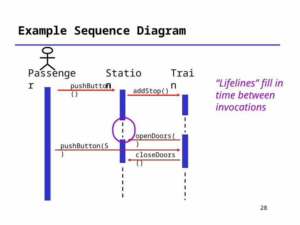
Sequence Diagrams
• A table– Columns are classes or actors– Rows are time steps– Entries show control/data flow
• Method invocations• Important changes in state

25
Example Sequence Diagram
Passenger
Station TrainpushButton() addStop()
openDoors()
closeDoors()
pushButton(S)
Classes & Actors

26
Example Sequence Diagram
Passenger
Station TrainpushButton() addStop()
openDoors()
closeDoors()
pushButton(S)
Method invocation
Note: These are all synchronous method calls. There are other kinds of invocations.

27
Example Sequence Diagram
Passenger
Station TrainpushButton() addStop()
openDoors()
closeDoors()
pushButton(S)
Invocation lifetime spans lifetimes of all nested invocations
28
Example Sequence Diagram
Passenger
Station TrainpushButton() addStop()
openDoors()
closeDoors()
pushButton(S)
“Lifelines” fill in time between invocations

29
Sequence Diagrams Notes
• Sequence diagrams– Refine use cases– Gives view of dynamic behavior of classes
• Class diagrams give the static class structure
• Not orthogonal to other diagrams– Overlapping functionality– True of all UML diagrams
30
Activity Diagrams
• Reincarnation of flow charts– Uses flowchart symbols
• Emphasis on control-flow
• Two useful flowchart extensions– Hierarchy
• A node may be an activity diagram
– Swim lanes
31
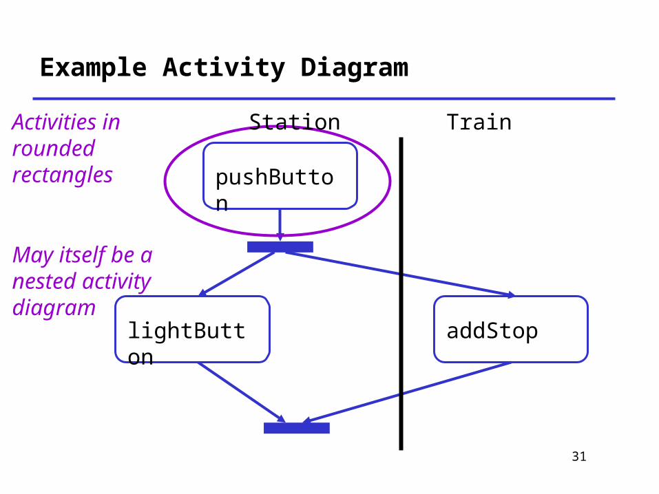
Example Activity Diagram
pushButton
lightButton addStop
Activities in rounded rectangles
May itself be a nested activity diagram
Station Train

32
Example Activity Diagram
pushButton
lightButton addStop
Concurrency, fork & join
Station Train

33
Example Activity Diagram
pushButton
lightButton addStop
Swim lanes show which classes/actors are responsible for which part of the diagram
Station Train
34
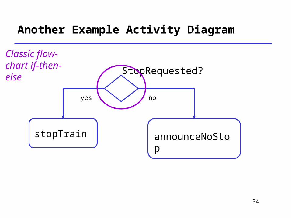
Another Example Activity Diagram
stopTrain announceNoStop
StopRequested?
yes no
Classic flow-chart if-then-else

35
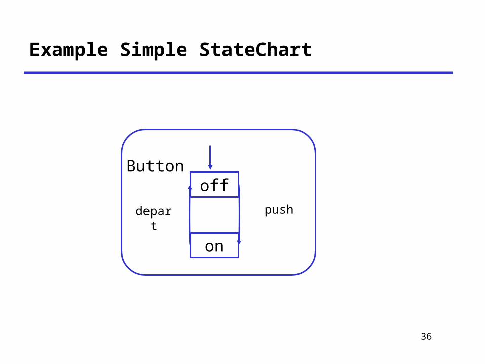
StateCharts
• Hierarchical finite automata– Invented by David Harel, 1983
• Specify automata with many states compactly
• Complications in meaning of transitions– What it means to enter/exit a compound state
36
Example Simple StateChart
off
on
pushdepart
Button
37
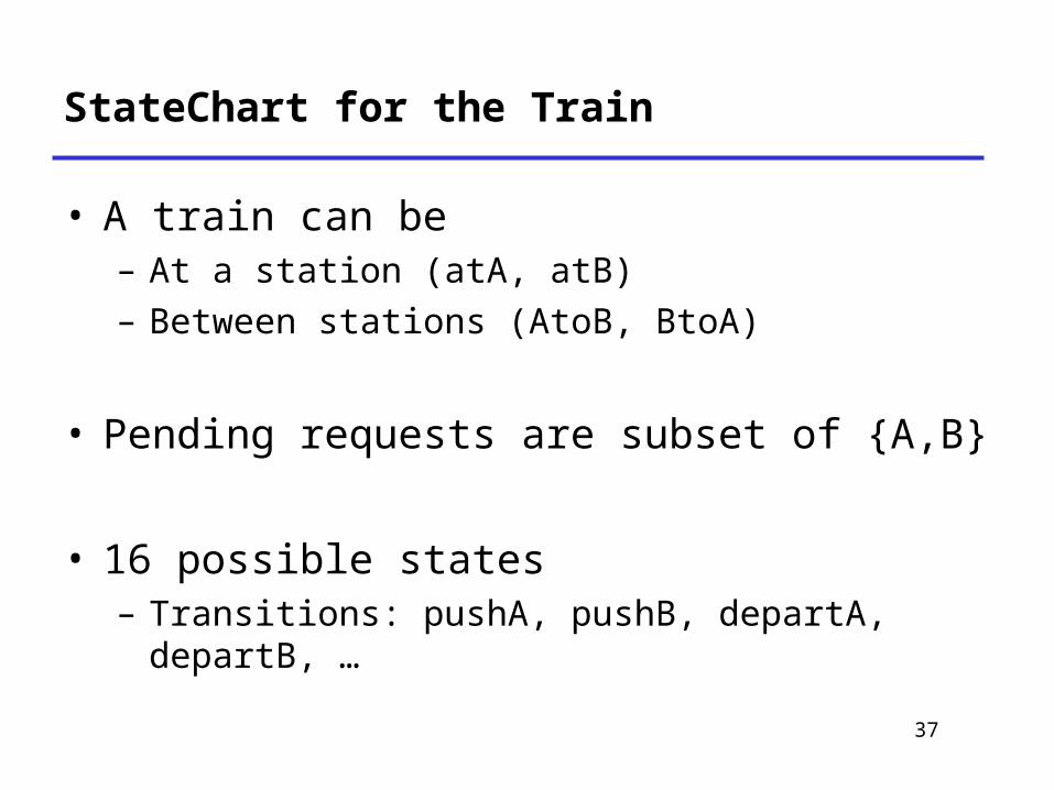
StateChart for the Train
• A train can be– At a station (atA, atB)– Between stations (AtoB, BtoA)
• Pending requests are subset of {A,B}
• 16 possible states– Transitions: pushA, pushB, departA, departB, …

38
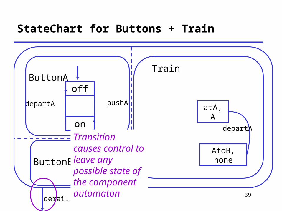
StateChart for Buttons + Train
off
on
pushAdepartA
ButtonA
ButtonB
Train
atA, A
AtoB, none
departA
derail
Dotted lines separate concurrent automata
39
StateChart for Buttons + Train
off
on
pushAdepartA
ButtonA
ButtonB
Train
atA, A
AtoB, none
departA
derail
Transition causes control to leave any possible state of the component automaton
40
Opinions about UML: What’s Good
• A common language– Makes it easier to share requirements, specs, designs
• Visual syntax is useful, to a point– A picture is worth 1000 words– For the non-technical, easier to grasp simple diagrams
than simple pseudo-code
• To the extent UML is precise, forces clarity– Much better than natural language
• Commercial tool support– Something natural language could never have
41
Opinions On UML: What’s Bad
• Hodge-podge of ideas– Union of most popular modeling languages– Sublanguages remain largely unintegrated
• Visual syntax does not scale well– Many details are hard to depict visually
• Ad hoc text attached to diagrams– No visualization advantage for large diagrams
• 1000 pictures are very hard to understand
• Semantics is not completely clear– Some parts of UML underspecified, inconsistent– Plans to fix

42
UML is Happening
• UML is being widely adopted– By users– By tool vendors– By programmers
• A step forward– Seems useful– First standard for high-levels of software
process– Expect further evolution, development of UML

43
Suggestions on using UML
• Requirements– Use Case Diagrams to illustrate use cases– Activity or Sequence Diagrams to illustrate
typical flow within a use case (scenarios)
• Design– Class Diagram for system architecture

44
Presentations (Requirements)
• 20 minutes/presentation– Hard limit!
• Format– · 15 minute presentation– ¸ 5 minutes Q&A
• Try to make your presentation useful– It is a plus to share negative experiences,
perhaps with solutions
45
Presentation 1: Requirements: ~10 slides
1. Project name and name of speaker
2. What does it do?– Brief description of what
project will do3. Who are the customers?
– List of customers you have contacted
– Comments on each4. What are the
requirements?– Bulleted list, use cases
5. What are the problems?– What don’t you know how
to solve yet?
• HTML, PDF, or PowerPoint
• Email to barrett@cs by 10am on the day of presentations.

46
Presentation 2: Design: ~10 slides, 20 min.
1. Project name and name of speaker• Different speaker than last time
2. How has the spec. changed• If nothing, say “none”
3. Design4. Plan
• Implementation and testing plan5. What are the problems?
– What don’t you know how to solve yet?
• HTML, PDF, or Powerpoint
• Email to barrett@cs by 10 a.m. on the day of the presentation

47
Presentations 3&4: Testing, Final Report
1. Different speakers (so everyone gets a chance)
2. More information on these coming later