umts services and applications
TRANSCRIPT

8/13/2019 UMTS Services and Applications
http://slidepdf.com/reader/full/umts-services-and-applications 1/51
6-65761Issue 4.0 en
© Nokia Networks Oy 1 (51)
3G SYSTRA
3G/UMTS Mobile Services
Training Document

8/13/2019 UMTS Services and Applications
http://slidepdf.com/reader/full/umts-services-and-applications 2/51
3G/UMTS Mobile Services
2 (51) © Nokia Networks Oy 6-65761Issue 4.0 en
The information in this document is subject to change without notice and describes only theproduct defined in the introduction of this documentation. This document is intended for theuse of Nokia's customers only for the purposes of the agreement under which the document issubmitted, and no part of it may be reproduced or transmitted in any form or means withoutthe prior written permission of Nokia. The document has been prepared to be used byprofessional and properly trained personnel, and the customer assumes full responsibilitywhen using it. Nokia welcomes customer comments as part of the process of continuousdevelopment and improvement of the documentation.
The information or statements given in this document concerning the suitability, capacity, orperformance of the mentioned hardware or software products cannot be considered bindingbut shall be defined in the agreement made between Nokia and the customer. However,Nokia has made all reasonable efforts to ensure that the instructions contained in thedocument are adequate and free of material errors and omissions. Nokia will, if necessary,explain issues which may not be covered by the document.
Nokia's liability for any errors in the document is limited to the documentary correction oferrors. NOKIA WILL NOT BE RESPONSIBLE IN ANY EVENT FOR ERRORS IN THISDOCUMENT OR FOR ANY DAMAGES, INCIDENTAL OR CONSEQUENTIAL (INCLUDINGMONETARY LOSSES), that might arise from the use of this document or the information in it.
This document and the product it describes are considered protected by copyright accordingto the applicable laws.
NOKIA logo is a registered trademark of Nokia Oyj.
Other product names mentioned in this document may be trademarks of their respectivecompanies, and they are mentioned for identification purposes only.
Copyright © Nokia Oyj 2004. All rights reserved.

8/13/2019 UMTS Services and Applications
http://slidepdf.com/reader/full/umts-services-and-applications 3/51
Contents
6-65761Issue 4.0 en
© Nokia Networks Oy 3 (51)
Contents
1 Module objectives ................................................................................ 5
2 Introduction to mobile applications .................................................... 6
3 Potential applications ........................................................................ 10 3.1 Applications categorisation from the business area point of view ......... 10 3.1.1 Person-to-person communications ....................................................... 11 3.1.2 Mobile Internet ..................................................................................... 12 3.2 Potential application utilising the UMTS circuit switched service .......... 13 3.2.1 Video call and video services ............................................................... 13 3.2.1.1 Video telephony ................................................................................... 14 3.2.1.2 Video download ................................................................................... 14 3.2.1.3 Video streaming ................................................................................... 15 3.3 Potential applications utilising the UMTS packet switched
service ...................................................................................... 15
3.3.1 Voice over IP ....................................................................................... 15 3.3.1.1 Push to talk over Cellular ..................................................................... 15 3.3.1.2 Voice and video over IP ....................................................................... 16 3.3.1.3 Point-to-multipoint, multicast via SGSN ................................................ 16 3.3.2 Data 17 3.3.2.1 Web browsing ...................................................................................... 17 3.3.2.2 Interactive games ................................................................................. 18 3.3.2.3 High-priority transaction services (E-commerce) ........... ....................... 18 3.3.2.4 Two-way control telemetry ................................................................... 18 3.3.2.5 E-mail (server access) ......................................................................... 19 3.3.2.6 Voice messaging and dictation ............................................................. 19 3.3.2.7 Presence .............................................................................................. 20 3.3.3 Multimedia Messaging Service (MMS) ................................................. 20 3.3.3.1 MMS Architecture ................................................................................ 22 3.3.3.2 MMS Flow examples ............................................................................ 23
4 User Location ..................................................................................... 29 4.1 Location Service (LCS) ........................................................................ 29 4.1.1 Cell ID based method........................................................................... 30 4.1.2 OTDOA-IPDL ....................................................................................... 30 4.1.3 GPS 31 4.2 Location Based Services (LBS) ............................................................ 31
5 Virtual Home Environment (VHE) ...................................................... 34 5.1 What is a Virtual Home Environment? .................................................. 34
5.1.1 Mobile applications from the USIM and terminal point of view .............. 35 5.2 (UMTS) SIM Application Toolkit - (U)SAT ............................................ 37 5.3 Mobile (Station Application) Execution Environment (MExE) ................ 39 5.3.1 Wireless Application Protocol (WAP)/ Wireless Telephony
Application (WTA) ..................................................................... 39

8/13/2019 UMTS Services and Applications
http://slidepdf.com/reader/full/umts-services-and-applications 4/51
3G/UMTS Mobile Services
4 (51) © Nokia Networks Oy 6-65761Issue 4.0 en
5.4 Customised Application for Mobile Network Enhanced Logic(CAMEL) ................................................................................... 41
5.5 Open Service Access (OSA) conception .............................................. 43 5.6 Nokia Mobile Internet solution (optional topic) ...................................... 45 5.6.1 Mobile Business (mBusiness) .............................................................. 46
5.6.2 Mobile commerce (mCommerce) ......................................................... 47
6 Review questions ............................................................................... 49
Further information ............................................................................................ 51

8/13/2019 UMTS Services and Applications
http://slidepdf.com/reader/full/umts-services-and-applications 5/51
Module objectives
6-65761Issue 4.0 en
© Nokia Networks Oy 5 (51)
1 Module objectives
The aim of this module is to give the student the conceptual knowledge needed forexplaining what the GSM/UMTS mobile applications are. Topics to be covered in
this module include the differentiation between UMTS services and applications, ageneral discussion of the Virtual Home Environment, and the introduction of themost important service platforms.
After completing this module, the participant should be able to:
• Outline the Virtual Home Environment concept (VHE)
• Briefly explain the difference between a tele-, bearer- and supplementary
service within the VHE concept
• Name the UMTS services
• Sketch the ideas of (U)SAT, MExE, CAMEL, and OSA
without using any references.

8/13/2019 UMTS Services and Applications
http://slidepdf.com/reader/full/umts-services-and-applications 6/51
3G/UMTS Mobile Services
6 (51) © Nokia Networks Oy 6-65761Issue 4.0 en
2 Introduction to mobile applications
In our everyday life we are familiar with the concept of a mobile service. Forexample, a mobile phone call is a mobile service. A short message (SMS) is another
type of application. As operators and subscribers evolve into the future, the need fordifferent types of applications is increasing. Today the subscribers expect anincreased number of applications and greater value. For an operator with a large
subscriber base, more usage time is one way of ensuring continuing growth. This
usage time, for example phone calls, has a limit on the amount everybody is willingto use. Therefore, when defining the 3G Specifications, the emphasis is on the
unlimited prospect of seamless services and applications that can be provided.
One common misconception that people have is that applications are introduced in
UMTS. This is not true, as GSM already offers both integrated network and IN(Intelligent Networks) applications. GPRS in today's network adds the facility of
supporting packet data (e.g. Internet) with relatively quick set-up and transfer times.
UMTS Services
The term application refers to “services as seen by the subscriber”. Applications
have not been standardized in UMTS. The (GSM/UMTS) network offers serviceelements, which are used by applications. The applications form the value added for
the subscriber (see also Next Generation Network Group). A set of services havebeen made available by UMTS, which are:
• Circuit switched services, which are the teleservices, such as speech call,
facsimile call, CS data.
• Packet switched services, which are based on the PS connectivity provided
by PDP contexts.
• message services, including SMS and CBS.
The services speech call, facsimile, and SMS are both services and applications.
“Circuit switched data” is only a service – the subscriber gets a circuit switchedbearer for data transport. The bearer itself adds no value to the subscriber. Thesubscriber requires the CS data bearer to run a data application, where content is for
instance exchanged between the handheld device and an application related contentserver. The same is true for packet switched services, which are used to establish a
packet switched bearer. Again, the PS bearer alone adds no value to the subscriber.But when the subscriber can use the bearer in combination with an application, thena value added is generated. For instance, a subscriber can use a PS bearer between
the handheld device and the Internet to gain content via the application
HTTP/TCP/IP.
Consequently, the GSM/UMTS services must be selected in such a way, that the
application running on top of it can be served in the best possible way.

8/13/2019 UMTS Services and Applications
http://slidepdf.com/reader/full/umts-services-and-applications 7/51
Introduction to mobile applications
6-65761Issue 4.0 en
© Nokia Networks Oy 7 (51)
Service model
Therefore, the spirit of the UMTS specifications is to separate the applications and
the network from each other as completely as possible. This can be expressed in themodel drawn in the following picture.
Service Platform Service Platform
Content Content
Access Methods:
- WCDMA
- GSM900/1800
- etc.
Open / Proprietary Interface
Open Interface
UE Node B RNC
Uu Iub/Iur Iu
Core Network
Applications Applications
Terminal & USIM 3G Network
Figure 1. Service model
In principle, the radio access network (RAN) could be implemented with any
technology but the core network (CN) and the user equipment (UE) must support theaccess method used.
The terminals and the network together form the physical platform. The service
platform layer maintains the applications offered and it is located on top of the
physical platform. It should be noted that this model is logical and in real life the
physical platform and service platform are somewhat mixed up together in the sameequipment. On the core network side, the service platform is often distributed on
many different pieces of equipment, for instance in the Home Location Register(HLR).
The interfaces between the physical platform and the service platform are eitheropen or proprietary. Where possible, the Nokia solution supports standardised
interfaces.
Service platforms offer completely open interfaces towards applications. Actually,
one of the requirements of UMTS is that the system must offer open interfaces forapplication development and this is it. For instance, WAP (Wireless Application
Protocol) is one occurrence of open application development interfaces.

8/13/2019 UMTS Services and Applications
http://slidepdf.com/reader/full/umts-services-and-applications 8/51
3G/UMTS Mobile Services
8 (51) © Nokia Networks Oy 6-65761Issue 4.0 en
Application provider model
Due to the layered structure presented previously, the commercial points related to
the application creation and provision will remarkably change compared to GSM. Inthe early phase of GSM, every application for the end user basically came from the
equipment vendor. Either it required fine-tuning of the equipment or the operator
was not able to establish a service itself. In UMTS, the open interfaces enable asituation where basically anyone may create a applications and create application
related content to be supplied to the end-users.
Bearer/Carrier Provider (3G Network)
Application Provider
Content Provider Content Provider Content Provider
Application Provider Application Provider
End-Users
Figure 2. Application Provider Model
From the point of view of the telecommunications business, the emphasis is moving
rapidly from equipment to application and content. This model, indirectly specified
in UMTS, fastens that development. Indications of this development can already beseen in the existing GSM networks.
For instance, stock exchange rates can be queried through the GSM network. In this
case, the carrier provider (operator) and application provider are the same, but thecontent for the service is queried somewhere else, such as from the stock exchange
database.
Service platforms
Service platforms are entities, which offer the implementation means for
applications. A service platform is a logical entity often containing several pieces of
equipment. As the majority of existing applications (December 2002) were adoptedfrom GSM:
• VMS (Voice Mail System) for Voice Call Completion
• Service Delivery Platform: A set of service enabling servers that supportdifferent types of applications. A typical example is the SMSC (Short
Message Service Centre) for Short Message Delivery.

8/13/2019 UMTS Services and Applications
http://slidepdf.com/reader/full/umts-services-and-applications 9/51
Introduction to mobile applications
6-65761Issue 4.0 en
© Nokia Networks Oy 9 (51)
• Service Creation & Execution Platform is built upon the principles of IN
(Intelligent Network) and is almost obligatory to provide the envisionedservices.
Fiber Fiber
AXC
MWR
ATM Access
Internet
RANCore Network
Control Plane
Gateway PlanePSTN
2GSGSN
3GSGSN GGSNRNC
BSC
Node B
BTS
Node B
HLR
3GMSC
NMS
VoiceServers
Service Creation& ExecutionPlatform
SCP
Service DeliveryPlatform
Figure 3. Core network service platform elements
The new WCDMA radio interface will improve the quality and convenience of these
applications. It will also enable higher packet data rates, which is highly importantfor the new e-mail and Internet services. The circuit connections can initially bemade to the GSM switches to provide speech and other circuit switched services ofup to 64 Kbps.

8/13/2019 UMTS Services and Applications
http://slidepdf.com/reader/full/umts-services-and-applications 10/51
3G/UMTS Mobile Services
10 (51) © Nokia Networks Oy 6-65761Issue 4.0 en
3 Potential applications
Applications are the “end user services”. They are no longer standardized. It is up tooperators and value added service providers to determine the need for an application
and implement them. GSM/UMTS offer the bearer and call control to exchangecontent and content related signaling information between the mobile device and theapplication driven content server.
Potential applications
The following is a list of the applications that have been planned for GSM/UMTS to
realize:
• News and traffic flashes
• Public video phoning
• Ticketing services and interactive shopping
• Desktop video conferencing
• Voice recognition and response
• Interactive and virtual school
• Universal SIM with credit card function
• Virtual banking
• Currency downloading
• Video on demand
• On-line library and books
In addition to these, the supplementary services used in GSM are available from the
very beginning of the 3G.
3.1 Applications categorisation from the business areapoint of view
The different potential applications can be categorized into five distinct groups:
• Person-to-Person Multimedia Communications
• Mobile Internet
•
Business Solutions• Mobile Commerce
• Location Based Services

8/13/2019 UMTS Services and Applications
http://slidepdf.com/reader/full/umts-services-and-applications 11/51
Potential applications
6-65761Issue 4.0 en
© Nokia Networks Oy 11 (51)
Although it is difficult to predict, which services will be the most popular; it is
foreseen that the more lucrative services will be those that are working together.
Micro-Payment
Transact Transact PIM
ChooseTheatre
MakeBooking
MakePayment
ChooseRestaurant
GetMap
GetTrain
GetBus
FindParking
MakeBooking
MakePayment
Enterin Diary
CreateReminder
CheckAvailability
Entertainment
Common Enabling Layer
Check - location- preferences- diary
Check - Credit Card Details
Check - Fund Availability
Check - Home Location- Preferences- Theatre Location
Travel
Figure 4. Sample of using a multitude of services
In the previous figure, we use searching based upon our location to find a theatre.The mobile network allows users to make an instant reservation (Nokia mCommercesolution). Then, as the user travels to the chosen theatre, the mobile network
provides a map application, assisted with location based services suggesting meansof traveling towards the destination. Finally the user updates a Personal Information
Management application (PIM) with the information of the travel and theatre.
3.1.1 Person-to-person communications
Person-to-person communications is the interaction and sharing of end user createdinformation between the individuals. Today, person-to-person communication is
mainly related to voice calls and Short Message Service (SMS). In 3G, person-to-person communications will evolve to new types of messaging and telephony,
including:
• Chat (one to many)
• Calendar and email (including synchronization)
• Rich call and video telephony
• Picture messaging and multimedia messaging
Evolution of messaging will bring richer content into the messages. With multimedia
messaging, it is possible to combine the conventional short messages with much

8/13/2019 UMTS Services and Applications
http://slidepdf.com/reader/full/umts-services-and-applications 12/51
3G/UMTS Mobile Services
12 (51) © Nokia Networks Oy 6-65761Issue 4.0 en
richer content type – photographs, images, and eventually also video clips. In
addition to sending messages from one hand set to another, it is also possible to sendmessages from handset to email.
SMS
PictureMessaging
MultimediaMessageService
MobileMultimedia
Text Text &Graphics
Digitalimageinput
Newcontenttypes
Time
Versatility of Contentand User Benefits
Figure 5. Development of person-to-person messaging
Student Facts:During the month of June 2001, around 20 billion SMSs were sent globally. InSeptember 2002, 27 billion of them were sent. During 1999 and 2000, Norwaysaw an increase of 1000% SMSs. Italy saw an increase of 700% during 7months.
3.1.2 Mobile Internet
The introduction of Wireless Application Protocol (WAP) has shaped the mobileindustry into the direction where mobile technology is combined with the Internet.
The added value provided by Mobile Internet (as opposed to fixed Internet) could besummed up with four key words:
• Personalized thus always relevant to me
• Available wherever I need it
• Immediacy information when I need
• Real time latest version, as it happens
The question to ask is: "What can I do with it?" The figures below give an exampleof how the Mobile Internet can be used for a subscriber's life style. The categories of
services can be divided into information and entertainment.

8/13/2019 UMTS Services and Applications
http://slidepdf.com/reader/full/umts-services-and-applications 13/51
Potential applications
6-65761Issue 4.0 en
© Nokia Networks Oy 13 (51)
INFOR-
MATION
NEWS
General Headlines Financial &
Business Politics Tabloids Culture &
Entertainment Sports Lottery
BANKING & FINAN-CIAL SERVICES
Stock indexes Stock prices Metal prices Stock alert Currency rates Interest rates Account balance Credit/debit balance Cheque balance Money transfers Bill payments Automatic call Account status
flash Stock purchase Financial products
purchase
LOCAL SERVICES(CITY GUIDE)
Taxi Restaurants Cinema Theatres Concerts Exhibitions
Night Clubs Emergency services Pharmacies Household
assistance Weather Time Directory services ATM Locator
BUY & SELL
Classifieds- Cars- Properties- Jobs
Auctions Shopping
-
Small dailyitems- Specific
promotions Tickets
TRAVEL
Traffic (traffic jams,radar, control,…)
Publictransportation
Navigation services Train schedules
Flight schedules Hotels Holiday packages
SpecialInterest
Mobile telephones Internet sites and
services Computers and
hardware Automobile
MUSIC
Ringtones Short clips
(e.g. MP3)
TV
Program-me schedules
Highlights
LIFESTYLE
Gastronomy Hobbies Fashion Parties
FUN
Jokes Sayings Dream
analysis
CHATS
Topicspecific
Private
PICTURES
Icons Logos Photos Postcards
GAMES
Puzzles Quizzes “Tamagotchi” Games Gambling/Betting
ASTROLO-GY
Horoscopes Astrolove Biorhythm Specific
Horoscopes
DATING
Chats Dating
services
ENTER-
TAINTMENT
Figure 6. Mobile Internet services
As mentioned previously in this module, there is a misconception that these servicesare only introduced in UMTS. However, there is nothing limiting the
operator/content provider in introducing these services today. Although in circuitswitched networks there are limitations in terms of speed and connection set-up. The
advantage of GPRS should overcome, or reduce, these limitations.
3.2 Potential application utilising the UMTS circuitswitched service
3.2.1 Video call and video services
A likely evolution of mobile video services is that they will evolve from the currentmultimedia messaging of still and animated pictures and presentations, to video
messaging and playback. Video download and video streaming services will followshortly after, though exactly when these services will be introduced will naturally
differ from country to country. Nokia believes that “See What I See” (SWIS), video
telephony and broadcasting will be interesting applications in the future.

8/13/2019 UMTS Services and Applications
http://slidepdf.com/reader/full/umts-services-and-applications 14/51
3G/UMTS Mobile Services
14 (51) © Nokia Networks Oy 6-65761Issue 4.0 en
Error! Objects cannot be created from editing field codes.
Figure 7 Evolution of mobile video technology
3.2.1.1 Video telephony
Thsi service refers to making or receiving a video call where the mobile user can see
as well as talk to the other person. In effect, it allows the user both visual and verbal
communications since users can see each other. The conversation experience can befurhter improved by allowing one or both users to see what the other person sees. It
is thus possible to not only see each other but a more general concept of sharing isallowed for
Error! Objects cannot be created from editing field codes.
Figure 8 Video call application
The mobile device’s display, including screen size and resolution, as well as local
memory, make mobile video content different from content from other media,making it essential to design the content to suit the mobile device and the method of
distribution. In order to ensure that video services take off, a vast database of video
content must be developed, one that is constantly improved with new ideas andsubstance. The video formats in which the video content has been encoded, such as
the open standards 3GPP file format, can be used throughout the evolution of video
services.
Error! Objects cannot be created from editing field codes.
Figure 9 Mobile video examples
3.2.1.2 Video download
This as the name implies, refers to the delivery of video clips to a mobile device,
usually through discovery such as browsing and then followed by a WAP or TCP/IP
session where the clip is sent to the device to be viewed or stored. Digital rightsmanagement will define the usage rules for commercial quality content, while theavailable memory capacity of the device will determine storage possibilities
In video downloading cases, wireless profile of TCP/IP is a key enabler for the
download of larger files. Although large video files can be downloaded over the

8/13/2019 UMTS Services and Applications
http://slidepdf.com/reader/full/umts-services-and-applications 15/51
Potential applications
6-65761Issue 4.0 en
© Nokia Networks Oy 15 (51)
WAP stack, the download time is substantially faster with the same network
bandwidth if the transfer is done over the TCP/IP stack. This is better for the user, asthere it reduces the ‘waiting’ time while the file is being delivered from a server to
the user’s device. The evolution of the underlying network to EDGE and WCDMAwill secure capacity and cost-effectiveness. Similarly, roaming agreements between
operators are required.
3.2.1.3 Video streaming
Streaming commonly indicates immediate consumption of on demand or live video
content on a mobile device and where the content is not stored on the device. Thismethod allows the consumption of large video fi les without any dependence on
device memory, since the file is not physically stored on the client. This can becompared to the broadcast model of watching television programs.
Control of Quality of Service is needed in the radio access and core network to
ensure that video applications work properly. This can be done by networkdimensioning and configuration to ensure sufficient capacity for streaming users.
Early GPRS is based on best effort, where capacity is shared evenly among the usersin a cell. In WCDMA and later EGPRS networks, it is possible to provide the user
with a guaranteed bit rate for good service performance.
3.3 Potential applications utilising the UMTS packetswitched service
One of the main reasons for the implementation of UMTS networks is the
anticipated demand for data services. This chapter presents different types of packetswitched services and some of the main requirements for these.
3.3.1 Voice over IP
The most well known use of voice telecommunication is telephony speech
(e.g. GSM), but with Internet and multimedia, a number of new applications will
require this scheme, for example voice over IP and video conferencing tools. Real-time conversation is always performed between peers (or groups) of live (human)
end-users. This is the only scheme where the required characteristics are strictlygiven by human perception (the senses).
3.3.1.1 Push to talk over Cellular
PoC is a direct, real-time voice communications service. The principle of the service
is simple: just push to talk. Thanks to the direct connection, calls can be started toboth individuals and groups with just a push of a key. The half-duplex (one way at atime) call connection is almost instant.

8/13/2019 UMTS Services and Applications
http://slidepdf.com/reader/full/umts-services-and-applications 16/51
3G/UMTS Mobile Services
16 (51) © Nokia Networks Oy 6-65761Issue 4.0 en
The technology uses the capabilities of the IMS (IP Multimedia Subsystem) as
specified by 3GPP. It is based on a half-duplex, always-on VoIP (Voice over IP)service over the second generation GSM/GPRS network. Push to talk uses the SIP
(Session Initiation Protocol) service architecture as SIP messaging, making newapplications - such as voice chat and group chat messaging - possible. Groups can
also be created using SMS, which is familiar and easy for the user to control.
3.3.1.2 Voice and video over IP
Videophone implies a full-duplex system, carrying both video and audio, and is
intended for use in a conversational environment. As such, the same delayrequirements as for conversational voice will apply in principle, with the added
requirement that the audio and video must be synchronized within certain limits toprovide 'lip-synch' (that is, synchronization of the speaker’s lips with the words
being heard by the end-user). In fact, due to the long delays in even the latest videocodecs, it will be difficult to meet these requirements.
Once again, the human eye is tolerant to some loss of information, so that some
degree of packet loss is acceptable depending on the specific video coder andamount of error protection used. It is expected that the latest video codecs will
provide acceptable video quality with frame erasure rates up to about 1%.
Figure 10. Video telephony
3.3.1.3 Point-to-multipoint, multicast via SGSN
When the user is looking at (listening to) video (audio), the scheme streams apply.
The real-time data flow is always aiming at a live (human) destination. It is a one-way transport called unidirectional continuous stream.
This scheme is one of the newcomers in data communication, raising a number of
new requirements in both telecommunication and data communication systems.

8/13/2019 UMTS Services and Applications
http://slidepdf.com/reader/full/umts-services-and-applications 17/51
Potential applications
6-65761Issue 4.0 en
© Nokia Networks Oy 17 (51)
• Audio streaming is expected to provide better quality than conventional
telephony, and requirements for information loss in terms of packet loss willbe correspondingly tighter. As with voice messaging, however, there is no
conversational element involved and delay requirements can be relaxed, evenmore so than for voice messaging. An example of audio streaming is the web
radio station.
The main distinguishing feature of one-way video is that there is no conversationalelement involved, meaning that the delay requirement will not be so stringent, and
can follow that of streaming audio. An example of one-way video is monitoring yourhome via the Internet
3.3.2 Data
Although there may be some exceptions, as a general rule it is assumed that from a
user point of view, a prime requirement for any data transfer application is toessentially guarantee zero loss of information. At the same time, delay variation isnot applicable. The applications, therefore, tend to distinguish themselves on the
basis of the delay that can be tolerated by the end user from the time the sourcecontent is requested until it is presented to the user.
The Release 5 feature HSDPA (High Speed Downlink Packet Access) marks a
similar boost for WCDMA that EDGE does for GSM. It provides a two-fold increasein air interface capacity and a five-fold increase in data speeds in the downlinkdirection. HSDPA also shortens the round-trip time between the network and
terminals and reduces variance in downlink transmission delay
3.3.2.1 Web browsing
In this category, we will refer to retrieving and viewing the HTML component of aweb page. Other components (e.g. images, audio/video clips) are dealt with under
their separate categories. From the user point of view, the main performance factor is
how fast a page appears after it has been requested.A value of 2 - 4 seconds per page is proposed. However, improvements on these
figures to a target figure of 0.5 seconds would be desirable.
Mobile browsing delivers formatted Web pages to the user’s terminal and displays
them on the screen, enabling interaction with active elements on the page, such aslinks and forms. In the case of “pull,” the user consumes the product by clickinglinks and form buttons to request the next page. Mobile browsing also supports
“push”which is an action initiated by the server to deliver content to the terminal.Users may receive a Service Initiation push message, asking for permission to
display a page, or a Service Load push message, which, depending on the user’ssettings, can automatically load a page and then display it, or simply have it ready inthe cache for immediate display later.

8/13/2019 UMTS Services and Applications
http://slidepdf.com/reader/full/umts-services-and-applications 18/51
3G/UMTS Mobile Services
18 (51) © Nokia Networks Oy 6-65761Issue 4.0 en
Error! Objects cannot be created from editing field codes.
Figure 11 Web browsing with modern mobile browser
3.3.2.2 Interactive games
Requirements for interactive games are obviously very dependent on the specific
game, but it is clear that demanding applications will require very short delays, and a
value of 250 ms is recommended consistent with demanding interactive applications.
Error! Objects cannot be created from editing field codes.
Figure 12 Interactive gaming
3.3.2.3 High-priority transaction services (E-commerce)
The main performance requirement here is to provide a sense of immediacy to theuser that the transaction is proceeding smoothly. A value of 2 - 4 seconds is
suggested to be acceptable to most users.
A mobile wallet in the terminal can improve the convenience of mobile commerce
significantly. By providing local storage of, for example, payment and accesscredentials and support or federated identity technologies, such as Liberty, the
terminal wallet reduces the number of actions required by the user during a browsingsession.
Instead of the consumer remembering and typing payment card numbers and accessprofiles (PINs and passwords), the mobile wallet can provide them to the serviceprovider automatically through an intuitive user interface. In addition, a mobile
wallet can extend this automation to shipping address information that wouldotherwise be entered manually. Lifecycle management can be facilitated by over-the-
air (OTA) provisioning of the credentials to be stored in the mobile wallet. Instead of
the user keying in the data manually, he can simply receive, for instance, credit carddetails from the card issuer over-the-air. Credentials storage is secure and protected
by terminal security architecture and a password. Future opportunities for the mobilewallet can include support for operator-based payment services, such as server -
wallets and premium SMS, new card association technologies for browser-basedpayments, such as 3D secure, as well as an open development environment.
3.3.2.4 Two-way control telemetry
Two-way control telemetry is included here as an example of a data service that
requires a real-time streaming performance. Two-way control implies a low allowed
delay. A value of 250 ms is proposed, but a key difference between the voice and

8/13/2019 UMTS Services and Applications
http://slidepdf.com/reader/full/umts-services-and-applications 19/51
Potential applications
6-65761Issue 4.0 en
© Nokia Networks Oy 19 (51)
video services in this category is the zero information loss tolerance, needed when
for instance controlling important industrial processes. There are billions ofmachines waiting to be able to communicate. An ice-cream vending machine wants
to tell the supplier that it’s running out of chocolate cones, enabling the vendingoperator to better schedule his onsite visits. An electricity meter wants to send
consumption figures to the energy provider’s billing system, thus providing morefrequent meter reading. Or the other way around – using your mobile handset, you
may want to activate the alarm system at your cottage remotely, check if the doors at
your home are locked or tell your greenhouse to water your plants.
3.3.2.5 E-mail (server access)
E-mail is generally thought to be a store and forward service, which in principle cantolerate very long delays. It is important, however, to differentiate between
communications between the user and the local e-mail server and server-to-servertransfer. When the user communicates with the local mail server, there is an
expectation that the mail will be transferred quite rapidly, although not necessarilyinstantaneously. Consistent with the research findings on delay tolerance for web
browsing, a requirement of 2 - 4 seconds is proposed.
Figure 13. Electronic postcard
3.3.2.6 Voice messaging and dictation
Requirements for information loss are essentially the same as for conversationalvoice, but the key difference here is that there is more tolerance for delay since there
is no direct conversation involved. The main issue therefore is how much delay can
be tolerated between the user issuing a command to replay a voice message and theactual start of the audio. There is no precise data on this, but a delay on the order of a
few seconds appears reasonable.

8/13/2019 UMTS Services and Applications
http://slidepdf.com/reader/full/umts-services-and-applications 20/51
3G/UMTS Mobile Services
20 (51) © Nokia Networks Oy 6-65761Issue 4.0 en
3.3.2.7 Presence
Presence is a familiar concept to those using instant messaging services on the fixed
Internet. With mobile phones, presence will not only enhance messaging but willintroduce a service of its own that can be used in many other applications and
services. It will be at the center of all communication and mobile telephony will
benefit from presence information just as it has done from messaging. Instantmessaging is the first presence-enabled application that utilizes presence information
in the operator's presence server.
Error! Objects cannot be created from editing field codes.
Figure 14 Presence groups
A definition of presence, is a dynamic variable profile of the user, which is visible to
others and used to represent oneself, share information and control services. Inessence, presence is two things: a user’s status to others and others’ status to theuser. Status may contain information such as personal and device status, location or
context, terminal capabilities and preferred contact method.
3.3.3 Multimedia Messaging Service (MMS)
The MMS evolution
SMS is currently the most successful data service in GSM. In September 2002, morethan 27 billion SMS messages were transmitted. It is expected, that SMS will grow
in numbers of transmitted messages. In the year 2002 about 11% of an operator’sincome was earned with the short message service.
Nokia was the first handheld supplier to use the SMS infrastructure for another kind
of application. Instead of just sending text messages, download of simple pictures orringing tone became possible with Nokia Smart Messaging phones. Smart messaging
enabled the subscribers to personalize their messages to a higher degree.
The great success of Smart Messaging resulted in a standard for enhanced SMScapabilities: Enhanced Message Service (EMS), which was developed by the 3GPP.
EMS allows the transmission and reception of ring tones, sounds, animations, simple
pictures, etc. Hereby, the user can even create own pictures and tones. EMS supportsboth phone personalization and person-to-person messaging. The main advantage of
EMS from the operator’s point of view is that no investment in an EMSinfrastructure is required. EMS is based on and uses the existing SMS infrastructure.
MMS was specified with UMTS Release 4. During the specification process, the3GPP worked with several assumptions: Firstly, the potential transmission rates will

8/13/2019 UMTS Services and Applications
http://slidepdf.com/reader/full/umts-services-and-applications 21/51
Potential applications
6-65761Issue 4.0 en
© Nokia Networks Oy 21 (51)
be higher than in the second generation, thus allowing a higher data rate and more
flexible bearer allocation. Secondly, many mobile phones will have colored screensand higher resolution than earlier models. Given the new options both in terms of
bearers and terminal capabilities, the aim was to specify a more advanced option fortransmitting pictures, music, text, and video. MMS was thus specified to allow the
transmission of larger messages, containing a wide range of content. It supportsperson-to-person communication, and both service providers and subscribers can
generate content.
timeline
SMStextonly
SmartMessaging
& EMS
Text,simple graphics,ringing tones
MultimediaMessaging
Service
music
video
stills
etc.
Figure 15. Short message evolution
The MMS message
An MMS message can be compared with a standardized envelope – neither content,nor size, was specified. The MMS message is represented by a standardized
presentation language: SMIL (Synchronized Multimedia Integration Language). A
SMIL page holds information on how, where, and when to display the differentmultimedia elements.
The media elements – such as pictures, text, and sound – are combined to a singlemessage, using MIME. MIME stands for Multipurpose Internet Mail Extension.
MIME is a standard, which specifies how several media are placed within a message.(In the Internet, the message is the email; in the mobile network, it is the MMS
message.)
A wide range of media types are supported, such as audio (e.g. MP3), video (e.g.
MP4), text (e.g. ISO-8859-1), and pictures (e.g. baseline JPEG). Several mobile
phone manufactures have agreed in supporting a minimum set of media types toguarantee interoperability.

8/13/2019 UMTS Services and Applications
http://slidepdf.com/reader/full/umts-services-and-applications 22/51
3G/UMTS Mobile Services
22 (51) © Nokia Networks Oy 6-65761Issue 4.0 en
S M S - m e s s a
g e
Standardised„envelope“:
encapsulatedmessages
Content:Minimum set ofsupported mediatypesrecommended:• text• audio• images• video
variable size
addressesMSISDN or URL
Figure 16. MMS “envelope”
MMS today
More than 40 operators have already started the commercial launch of MMS
(December 2002). The GPRS infrastructure is currently in use for the MMStransport. MMS over WAP is the common way nowadays to transfer MMS message.
But MMS was specified independent from WAP, so other means of MMS transport
may be possible in the future.
3.3.3.1 MMS Architecture
The MMS Architecture consists of several network entities. Please note, that some of
them can be combined within a single network element.
• MMS User Agent (UE) MMS is based on the client server principle. A MMS UA can reside on themobile equipment. But it can be also made available on external devices, such as
laptops, PDAs, and other devices. These external devices can be connected to a
UE to use MMS via the radio interface. But MMS was specified in such a way,that it can be deployed e.g. on a fixed network personal computer.
The MMS UE interacts with the Multimedia Message Service Environment
(MMSE). The MMSE incorporates MMS service elements, which are responsiblefor the delivery and storage of MMS messages. The MMSE entities are the
• MMS Server
This network entity is responsible for managing incoming and outgoingmessages. It is also in use as MMS storage.
• MMS Relay This network element is responsible for the interworking between different

8/13/2019 UMTS Services and Applications
http://slidepdf.com/reader/full/umts-services-and-applications 23/51
Potential applications
6-65761Issue 4.0 en
© Nokia Networks Oy 23 (51)
messaging systems. It can be connected to voice mail servers, E-mail servers,
Fax servers, etc. In addition to that, it is also responsible for CDR generation.
Although MMS Server and MMS Relay were specified as two individual networkentities in UMTS Release 4, most vendors are offering their functionalities in one
network element. Nokia calls its MMS Server/Relay MMS Center. MMS over
WAP is currently the common way to transfer MMS message. But MMS wasspecified independently from WAP, so other means of MMS transport may bepossible in the future
The figure below shows the MMSC including its reference points (MM1 to MM8).Please note, that most reference points are not open! Only the format of the user data
is specified. (Reference point MM2 is between the MMS Relay and the MMSServer.)
MMSC enter
HLR
Subscriber
database
Externalapplication
MM1
MM5
MM6MM7
MM8I-MMSCMM4
Billingsystem
MM3
Legacysystems
Figure 17. MMS Center and its reference points
3.3.3.2 MMS Flow examples
UE to UE MMS transfer
In this example, we outline an MMS transfer between two UEs. Hereby, we assume
that the multimedia messages are transmitted via WAP. Before multimedia messages
can be exchanged, MMS related signalling between the MMS UA and the MMSCenter must take place. To transmit the signalling information, we need a bearer
between the UE and the MMS Center. In this example, a bearer is made available viathe packet switched domain. A PDP context between the UE and the “external PDN”WAP was established. This bearer is used to transmit MMS messages over WAP.
8/13/2019 UMTS Services and Applications
http://slidepdf.com/reader/full/umts-services-and-applications 24/51
3G/UMTS Mobile Services
24 (51) © Nokia Networks Oy 6-65761Issue 4.0 en
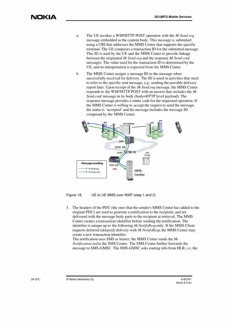
a. The UE invokes a WSP/HTTP POST operation with the M-Send.req
message embedded as the content body. This message is submittedusing a URI that addresses the MMS Center that supports the specific
terminal. The UE composes a transaction ID for the submitted message.This ID is used by the UE and the MMS Center to provide linkage
between the originated M-Send.req and the response M-Send.conf messages. The value used for the transaction ID is determined by the
UE, and no interpretation is expected from the MMS Center.
b. The MMS Center assigns a message ID to the message whensuccessfully received for delivery. The ID is used in activities that need
to refer to the specific sent message, e.g. sending the possible delivery
report later. Upon receipt of the M-Send.req message, the MMS Centerresponds to the WSP/HTTP POST with an answer that includes the M-
Send.conf message in its body (body=HTTP level payload). Theresponse message provides a status code for the requested operation. If
the MMS Center is willing to accept the request to send the message,the status is ‘accepted’ and the message includes the message-ID
composed by the MMS Center.
M-Send.req
M-Send.conf
Message sending
SGSN
GGSN
GPRS BB
MSC /VLR/HLR
SMSCenter
BTSBSC
BTSBSC
WAP GW
PPGMMSCenter
Figure 18. UE to UE MMS over WAP (step 1 and 2)
3. The headers of the PDU (the ones that the sender's MMS Center has added to theoriginal PDU) are used to generate a notification to the recipient, and aredelivered with the message body parts to the recipient at retrieval. The MMS
Center creates a transaction identifier before sending the notification. Theidentifier is unique up to the following M-NotifyResp only. If the MMS Client
requests deferred (delayed) delivery with M-NotifyResp, the MMS Center maycreate a new transaction identifier.The notification uses SMS as bearer; the MMS Center sends the M-
Notification.ind to the SMS Center. The SMS Center further forwards the
message to SMS-GMSC. The SMS-GMSC asks routing info from HLR, i.e. the

8/13/2019 UMTS Services and Applications
http://slidepdf.com/reader/full/umts-services-and-applications 25/51
Potential applications
6-65761Issue 4.0 en
© Nokia Networks Oy 25 (51)
location of the MSC that the recipient UE was last connected with
(SendRoutingInfoForShortMs) . SMS-GMSC forwards the message to MSC
(ForwardShortMessage). MSC checks VLR to make sure that the UE has not
been barred or otherwise restricted from using the network (SendInfoForMT-
SMS). MSC forwards the message through the BSS to the receiving UE.
4. The information in M-Notification.ind includes the URI that will be used toactually retrieve the message in a subsequent operation by the receiving
terminal. The terminal may use additional information about the message (e.g.
message size, expiry) to determine its behaviour. For example, the UE may delaythe retrieval of the message if it exceeds a defined size. The receiver of the M-
Notification.ind tells the action to be taken to the MMS Center with the M-
NotifyResp.req, which is routed to the MMS Center the same way as the M-
Notification.ind .
M-Notification.ind
M-NotifyResp.req
Sending notificationDeferring message
SGSN
GGSN
GPRS BB
MSC/VLR/HLR
SMSCenter
BTSBSC
BTSBSC
WAP GW
PPGMMSCenter
Figure 19. UE to UE MMS over WAP (step 3 and 4)
5. The URI (MMS Center address) required for the retrieval, sent in the preceding
M-Notification.ind message, is used in the GET request.
6. The data returned (M-Retrieve.conf) includes the multimedia message. Theheader component can provide additional information, such as the tariff class,
which is useful in AT messages.7. The MMS Center may decide to request an acknowledgement from the UE to
confirm the delivery status of the retrieval. It may make this decision based on
whether it needs to provide a delivery notice back to the originating UE or not.Alternatively, it may make that decision based upon an expectation that it would
then be able to delete the message from its own store.

8/13/2019 UMTS Services and Applications
http://slidepdf.com/reader/full/umts-services-and-applications 26/51
3G/UMTS Mobile Services
26 (51) © Nokia Networks Oy 6-65761Issue 4.0 en
WSP GET.req
M-Retrieve.conf
Fetching message
M-Acknowledge.req
SGSN
GGSN
GPRS BB
MSC/VLR/HLR
SMSC enter
BTSBSC
BTSBSC
WAP GW
PPGMMSCenter
Figure 20. UE to UE MMS over WAP (step 5, 6, and 7)
8. The MMS Center sends the M-Delivery.ind message to the originating MS using
WAP PUSH to inform when message delivery has occurred.The Message ID identifies the message. It is generated when the original messageis posted. It also provides addressing information of the originally targeted entity.
9. M-read-rec.ind message is sent by the receiver’s UE to the MMS Center toinform when the receiver has opened the message.
10. The MMS Center sends the M-read-orig.ind message to the originating MS using
WAP PUSH to inform when the the receiver has opened the message.

8/13/2019 UMTS Services and Applications
http://slidepdf.com/reader/full/umts-services-and-applications 27/51
Potential applications
6-65761Issue 4.0 en
© Nokia Networks Oy 27 (51)
M-Delivery.ind
Delivery reportRead-Reply
M-read-rec.ind
M-read-orig.ind
SGSN
GGSN
GPRS BB
MSC/VLR/HLR
SMSCenter
BTSBSC
BTSBSC
WAP GW
PPGMMSCenter
Figure 21. UE to UE MMS over WAP (step 8, 9, and 10)

8/13/2019 UMTS Services and Applications
http://slidepdf.com/reader/full/umts-services-and-applications 28/51
3G/UMTS Mobile Services
28 (51) © Nokia Networks Oy 6-65761Issue 4.0 en
E-Mail and MMS
E-Mails are nowadays a very popular means of communication both in business and
private. Here we can see a flow example of mobile E-mail transfer via MMS.
The MMS Center (MMS Relay functionality) converts the MM to an E-mailmessage and sends it to the Mail Server. The communication between Mail GW and
Mail Server is based on SMTP (/MIME) protocol. SMTP understands only pure textbased data and is used for the actual data transfer. MIME is used for attachment
support. The Mail Server acknowledges the MMS Center that it has received the
message. This is an acknowledgement belonging to the SMTP protocol.
M-Send.req
M-Send.conf
SMTP Mailmessage
SMTP-levelacknowledgement
E-mailserver
GPRS BB
GGSN SGSN
IP network
WAP GW
BTSBSC
MMSCenter
Externalapplication
Figure 22. E-mail connectivity

8/13/2019 UMTS Services and Applications
http://slidepdf.com/reader/full/umts-services-and-applications 29/51
User Location
6-65761Issue 4.0 en
© Nokia Networks Oy 29 (51)
4 User Location
For a mobile subscriber, the current location of his terminal may add value to him.His terminal equipment can be combined with a navigation aid, which helps the
subscriber to find his route in a foreign city. Knowing the user’s location is alsohelpful for emergency services in order to help the calling person faster.
Two concepts have to be separated, when we talk about the subscriber’s location:
• Location Service (LCS) LCS offers the possibility to identify the current location of the subscriber’s
terminal. The current location is reported in a standard format, such asgeographical co-ordinates. The location information can be made available
to the subscriber himself, the ME, the network operator, the service operator,
and for PLMN internal operations. LCS is specified.
• Location Based Service (LBS) LCS can be used to enable the provision of location based services (LBS).
These applications are service provider specific and are not specified.
4.1 Location Service (LCS)
LCS, which can be offered without subscription to basic telecommunication
services, reports the location of the subscriber’s terminal. The location informationcan be used for charging, lawful interception, emergency calls, positioning services,
as well as location based services (LBS).
A set of location services exists. They are characterized by following attributes,which vary with from location service to location service:
• Accuracy
describes the difference of the ME actual location and its estimated (andreported) location
• Privacy
describes the confidentiality of the location information
• Coverage area
describes the geographical area, within which the location service isadequately supplied
• Transaction rate
describes how frequently the location measurement has to be conducted to
support the location service.
Standard UE positioning methods
The standard positioning methods supported within GSM/UMTS Rel. 99:

8/13/2019 UMTS Services and Applications
http://slidepdf.com/reader/full/umts-services-and-applications 30/51
3G/UMTS Mobile Services
30 (51) © Nokia Networks Oy 6-65761Issue 4.0 en
• Cell ID based method
• OTDOA-IPDL (Observed Time Difference of Arrival -Idle Period Downlink)
• GPS (Global Positioning System).
These will be briefly explained in the following.
4.1.1 Cell ID based method
In the cell ID based (that is, cell coverage) method, the position of an UE isestimated with the knowledge of its serving base station. The information about the
serving base station and cell may be obtained by paging, location area update, cellupdate, URA update, or routing area update.
4.1.2 OTDOA-IPDL
OTDOA-IPDL (Observed Time Difference of Arrival - Idle Period Downlink) is a
method with network configurable idle periods (In the Nokia Solution, it has beennamed mCatch)
The OTDOA-IPDL method involves measurements made by the UE and LMU
(Location Measurement Unit) of the UTRAN frame timing. For instance, theobserved time difference between different System Frame Numbers (SFN) can be
used. These measures are then sent to the SRNC (Serving Radio Network Controller)
where the position of the UE is calculated through triangulation estimate. Thelocation can here be defined down to between 70 - 50 meters.
The Base Station may provide idle periods in the downlink in order to potentially
improve the hear ability of neighboring BSs. The support of these idle periods in the
UE is optional. The support of idle periods in the UE means that the OTDOAperformance is improved when idle periods are available. Alternatively, the UE mayperform the calculation of the position using measurements and assistance data.

8/13/2019 UMTS Services and Applications
http://slidepdf.com/reader/full/umts-services-and-applications 31/51
User Location
6-65761Issue 4.0 en
© Nokia Networks Oy 31 (51)
BTS
BTS
BTS
Figure 23. Locating the subscriber
4.1.3 GPS
GPS (Global Positioning System) is one approach. These methods make use of UEs,
which are equipped with radio receivers capable of receiving GPS signals. The UEreceives signals from many satellites and the position of the UE can be calculated
very accurately. But one has to remember that there has to be a line of sight to the
satellites, which means that the GPS does not work properly indoors or in bad
weather conditions.
4.2 Location Based Services (LBS)
Location based services do not form a separate application category of their own;rather combine LCS information with an application. Applications like games,mobile chat and mCommerce among others can be location-dependent. Please note,
that location based services are not standardized.
Location based services – Integrity, security and service related issues
Different applications can access information on the subscriber's location. The
standards dictate that the subscriber can control whether the location information iskept or not (except if there is local government legislation).
An example of how useful this location information is could be a car device that can
download maps or information based upon your location.

8/13/2019 UMTS Services and Applications
http://slidepdf.com/reader/full/umts-services-and-applications 32/51
3G/UMTS Mobile Services
32 (51) © Nokia Networks Oy 6-65761Issue 4.0 en
Error! Objects cannot be created from editing field codes.
Figure 24 Location Based Service examples
Location aware applications and services stand out because they provide theconsumer with:
• Enhanced personal navigation and route finding. For instance, by listeningto the turn-by-turn directions on how to get to a meeting.
• Enhanced personal communication when using e-mail or MMS: For
example, the user can receive a picture with attached location as an
invitation to a house-warming party.
• Location aware personalized information, e.g. “where are the nearest
restaurants?” This can be done with no need to enter the current address or
city district information, making the service faster and easy to use.
• Location aware games and entertainment, e.g. “catch the enemy spiesaround you while taking the bus to school”.
• Increased safety, e.g. locating lost hikers.
• Professional tracking services e.g operate a fleet of trucks and optimize
usage knowing where they are.
In many countries this is a legal requirement in the case of emergency calls.
For example in the U.S., the Federal Communication Commission (FCC) has statedthat, by October 2001, emergency calls from mobile stations should be located with
accuracy of 125 meters or better. This E911 requirement has been the mostimportant single driving factor for current MS location activity.
Operators can also benefit from location information for network planning purposes.
They can track user movements and detect hot spots with dense traffic. Operatorscan delineate areas with poor radio coverage or use location information to enhance
basic services. Special tariff zones provide a particularly good example of such aservice enhancement. A cellular operator can offer reduced tariffs for subscriberswhen they call from their home zone.
However, operators can earn revenue from offering related position servers, such aslocation specific advertising. This is because they know the user's location, personal
profile information or segmented channel. Push advertisements can be subscription
based so that the mobile user can indicate to the operator the information he is
interested in, according to his personal profile.

8/13/2019 UMTS Services and Applications
http://slidepdf.com/reader/full/umts-services-and-applications 33/51
User Location
6-65761Issue 4.0 en
© Nokia Networks Oy 33 (51)
Figure 25. Sample application
Location information can be utilized by the applications in many different ways. For
instance, by knowing the location, the menu of available services can be narroweddown to the ones that are interesting in relation to the location. Furthermore, the
content could change according to the location; for example, information of theclosest restaurants or the closest hotels could pop up on the mobile terminal's screen
based on the current location.
As you imagine, there is an endless amount of services that could utilize theinformation. For an operator, the existing network can be utilized although new
network elements are needed to help in taking measurements from the network and
location servers. Also, supporting servers are also needed.
Today's networks and mobiles also have location-based services, based upon the cell
ID and location area. This information is used already for charging and routing ofcalls.

8/13/2019 UMTS Services and Applications
http://slidepdf.com/reader/full/umts-services-and-applications 34/51
3G/UMTS Mobile Services
34 (51) © Nokia Networks Oy 6-65761Issue 4.0 en
5 Virtual Home Environment (VHE)
5.1 What is a Virtual Home Environment?
With GSM systems, one obvious drawback as far as roaming is concerned was theportability of the subscriber services. In order to increase the value added to the
subscriber – and thus the potential to earn revenue for the operator – a wide range of
personalized services are expected. If a large set of diversified applications exist,which are not specified, a framework has to be designed to enable seamless
application provisioning between networks. From the subscriber’s point of view, the
applications should be always available, regardless of location, and the application ispresented to him in the same way as if he is in his home PLMN.
Virtual Home Environment (VHE) is a concept for Personal Service Environment
portability across network boundaries and between terminals. The purpose of VHE isthat users should consistently be presented with the same personalized features inany terminal, any network and any location. User Interface customization and
services should be provided in a seamless manner between networks and terminals(within the capabilities of the terminal and the network). Currently; CAMEL,MExE, OSA and USAT are the mechanisms supporting the VHE concept.
Error! Objects cannot be created from editing field codes.
Figure 26. Subscriber's expectations: Seamless services
Each application toolkit has a specified application execution environment. Theapplication execution environment is used to run specific, non-standardized
applications. The options to personalize applications exist. The application toolkitsfor operator specific services are (U)SAT, MExE, and CAMEL.
The VHE can be viewed both from the user perspective and network perspective.
From a users point of view VHE is enabled by user profiles as in the figure below.The home environment allows a user to personally manage one or more user profiles
(e.g. activate, modify, deactivate etc.) The network side of VHE; (the Home
Environment and Home Environment –Value Added Service Provider) is also able tomanage one or more user profiles (e.g. activate, modify, deactivate etc.).
Furthermore it is necessary to enable the identification of a user's personalized dataand services information directly or indirectly from the user's profile and anauthorized Home Environment –Value Added Service Provider must have access the
user's profile. In some cases it required that Value Added Service Providers are

8/13/2019 UMTS Services and Applications
http://slidepdf.com/reader/full/umts-services-and-applications 35/51
Virtual Home Environment (VHE)
6-65761Issue 4.0 en
© Nokia Networks Oy 35 (51)
enabled to control and have limited access to the user's profile (e.g. for general user
preferences and subscribed services information).
Error! Objects cannot be created from editing field codes.
Figure 27 VHE; A set of service control from the user point of view
The home environment (VHE) from a network point of view is designed to be
able to provide and control services to the user in a consistent manner even in
cases when a user is roaming. It is also necessary to provide the means to
create and maintain a set of user profiles and support the execution of services
through its Service Toolkits in the network, the USIM and in the ME. The
VHE must be able to uniquely identify the user in any of thetelecommunication networks supported by the Home Environment.
Error! Objects cannot be created from editing field codes.
Figure 28 VHE from a network point of view
5.1.1 Mobile applications from the USIM and terminal point of view
In principle, a UMTS application is anything that can be delivered via a UMTS
bearer. This opens a wide range opportunities, but, on the other hand, it sets high
requirements for the terminals. As in GSM, the UMTS mobile phone is made of twocomponents, the USIM and the terminal:

8/13/2019 UMTS Services and Applications
http://slidepdf.com/reader/full/umts-services-and-applications 36/51
3G/UMTS Mobile Services
36 (51) © Nokia Networks Oy 6-65761Issue 4.0 en
Figure 29. SIM card
Because nobody requires every potential application (and is willing to pay all the
development costs which come with the application), terminal differentiation willoccur.
The standards have specified how additional network-independent services, such asSAT and MExE, should operate within terminals (see the next subsections).
Mobile terminal operating systems
A mobile terminal consists of hardware, an operating system, and applications. Thethree main contenders to set the standard for handheld operating systems are:
• Symbian with its EPOC operating system
• Microsoft with Windows CE (Consumer Electronics)
• 3Com with its Palm operating system
The Nokia wireless operating system for the next generation of smart phones,including the 9210(i) Communicator, is the EPOC operating system. By using a
standard operating system, it means that applications that are not dependent on aparticular phone can be built. This should open the way for more applications forsubscribers.
• The UMTS SIM (USIM) has
open application programminginterfaces (APIs). The option for
download application programs
exist.• The mobile equipment (ME),
which is also called mobileterminal (MT), is able to handle
RT/NRT bearers. Depending on
the application platforms it
supports, open application
programming interfaces support
the execution of applications on
the ME.

8/13/2019 UMTS Services and Applications
http://slidepdf.com/reader/full/umts-services-and-applications 37/51
Virtual Home Environment (VHE)
6-65761Issue 4.0 en
© Nokia Networks Oy 37 (51)
Figure 30. Sample Symbian operating system
5.2 (UMTS) SIM Application Toolkit - (U)SAT
General idea of APIs
It is possible to specify open Application Programming Interfaces (APIs) for themobile equipment (ME) and the SIM-card. Application programs can then use these
APIs. (U)SAT specifies APIs for the Subscriber Identity Module (SIM). In other
words, this APIs represent an enhanced set of SIM-ME interfaces. The SIM-MEinterfaces are used by the SIM-card to trigger ME functions and vice versa. The
SIM-card cannot be accessed from outside application servers. There is only oneexception: If the supplier of the SIM-card allows it, application programs can be
downloaded on the SIM.
The APIs for the ME are called terminal adaptation functions. They can be used to
interact directly with higher layer protocols such as USSD (UnstructuredSupplementary Service Data), SM (Session Management), CC (Call Control), and
SMS protocols. The ME can be accessed from external application servers.
(U)SAT working principle
Universal Subscriber identity module Application Toolkit (USAT) provides astandardized execution environment for applications stored on the USIM/SIM card
and the ability to utilize certain functions of the supporting mobile equipment.
SAT/USAT provides mechanisms which allow applications, existing in theUSIM/SIM, to interact and operate with any ME which supports the specified
mechanism(s) thus ensuring interoperability between a USIM/SIM and an ME,
independent of the respective manufacturers and operators. A transport mechanism isprovided enabling applications to be down-loaded and/or updated.

8/13/2019 UMTS Services and Applications
http://slidepdf.com/reader/full/umts-services-and-applications 38/51
3G/UMTS Mobile Services
38 (51) © Nokia Networks Oy 6-65761Issue 4.0 en
The central idea of USAT is to execute an application program on the SIM-card.
Information required for the application can be retrieved from an application relatedcontent server. The location of the content server and how to establish a connection
to the content server is specified in the application program on the SIM-card
Error! Objects cannot be created from editing field codes.
Figure 31 SAT / USAT concept view
Example
Content provider can remotely provision content to user’s mobile equipment byexchanging codes embedded in short messages between the application client on the
SIM and the content/application server. In the (U) SAT specification, SMS is a key
mechanism for personalizing the SIM in each user’s GSM phone. In the figurebelow, a simple service request and response by means of SAT is illustrated. As you
can see, most of the interaction takes place locally between the user and the MS/UE.Only the specific service request and the response are transmitted as short messages
in the air interface.
Error! Objects cannot be created from editing field codes.
Figure 32. SAT service example – weather forecast service
(U)SAT and security
A significant aspect of SAT/USAT is the highly secure environment provided by the
USIM/SIM card. This is further enhanced by the fact that the subscriber and the
issuer of the USIM/SIM and also the SAT/USAT applications have a "trustedrelationship" (e.g. the subscriber trusts the issuer of the card to charge correctly for
the resources used). This allows certain features, such as call control, to be
implemented with a degree of freedom, which would not be acceptable in a "non-trusted relationship". Because of this, (U)SAT is often seen as prerequisite for
applications with high security requirements, such as mobile banking and mobile
commerce.

8/13/2019 UMTS Services and Applications
http://slidepdf.com/reader/full/umts-services-and-applications 39/51
Virtual Home Environment (VHE)
6-65761Issue 4.0 en
© Nokia Networks Oy 39 (51)
5.3 Mobile (Station Application) Execution Environment(MExE)
MExE working principle
Mobile Execution Environment (MExE) provides a standardized executionenvironment in an ME, and an ability to negotiate the Mobile Equipments supported
capabilities with a MExE service provider, allowing applications to be developed
independently of any UE platform. A User Equipment (consisting of the ME and
SIM/USIM) can then be targeted with a range of implementations for MExE fromsmall devices with low bandwidth, limited displays, low processor speeds, limited
memory, MMI etc. At the other end of the scale are sophisticated User Equipmentswith a complete MExE execution environment
The aim of MExE is to provide a comprehensive and standardized environment on
the mobile equipment (ME) for executing operator or service provider specificapplications. MExE is designed as a full application execution environment on the
mobile terminal. A set of mobile terminal operating system such as Symbian orWindows CE can be used, which were optimized for small, handheld devices such asmobile phones or PDAs. Similar to (U)SAT, a set of open interfaces (so-called
terminal adaptation functions) are specified for the ME. These standardized
interfaces allow the execution of applications on the handheld device, an interaction
with external application related content servers, independent of the used operatingsystem.
Error! Objects cannot be created from editing field codes.
Figure 33 MExE architecture
Strongly simplified, we can say that MExE converts a mobile phone to a small
mobile computer. Manufactures of mobile phones have agreed in using WAP/WTAand/or Java virtual machines in order to design and program applications locally on
the mobile equipment. For that reason, WAP/WTA and Java were explicitlymentioned in the MExE specifications. Because of that, WAP/WTA and Java are
listed below in separate subsections. Please note, that neither WAP nor Java are
specified within MExE.
5.3.1 Wireless Application Protocol (WAP)/ Wireless Telephony Application(WTA)
The Internet and mobile communication were the fasted growing markets in the 90s.Consequently, solutions were searched after to allow mobile Internet access. A
standard for mobile Internet access must be globally unified future proof and suitable

8/13/2019 UMTS Services and Applications
http://slidepdf.com/reader/full/umts-services-and-applications 40/51
3G/UMTS Mobile Services
40 (51) © Nokia Networks Oy 6-65761Issue 4.0 en
for the radio interface limitations of several mobile communication standards. The
independence from a mobile communication standard was archived by specifyingWAP bearer independent. Also security aspects have to be considered for a wireless
Internet access in order to avoid eavesdropping.
WAP was released 1999 as new mobile Internet protocol standard. WAP was
explicitly designed to meet the challenge of an efficient radio interface usage. Inaddition to that, a content format was defined which enables the display of contenton small screen handheld devices.
WAP working principle
Basically the WAP architecture is similar to the “normal” Internet architecture:
There is the client sending a request, and on the other side there is a server, which
returns response to the client. The special issue about WAP is given by the fact thatthe client is a mobile station.
The content for the mobile phones is stored on standard WWW servers. Thus, they
use TCP/IP. A WAP Gateway between the mobile phone client and the WWW
server is required to translate WAP into the standard Internet format. (Http/TCP/IP).Besides translating the protocols the WAP Gateway also compresses the text based
Internet content to a binary format that is used on the air interface.
WWWServer
WAPuser
agent
WAPGateway
response (WML)
coded request (URL)URL request
coded response (bin. WML)
decoding
coding
Figure 34. WAP infrastructure
Within WAP, the Wireless Markup Language (WML) is standardized based on the
XML framework. WML copes with the problem that normal HTML pages are toobig to be shown on most handheld devices like PDAs and mobile phones. One
problem is rooted in the fact that HTML has no fixed page size. WML consequentlyreduces the page size dramatically to a size that can be presented on a mobile device
screen. These small pages are called cards. The content of one card will never besufficient for an application and so the application content is spread upon a whole
stack of cards that is called a deck . As the content is distributed between severalcards in one deck, a navigation trough different cards is required, which is one of the
most demanding and time consuming tasks when writing WML applications. Links

8/13/2019 UMTS Services and Applications
http://slidepdf.com/reader/full/umts-services-and-applications 41/51
Virtual Home Environment (VHE)
6-65761Issue 4.0 en
© Nokia Networks Oy 41 (51)
within a WML deck refer to the same deck they are carried out without delay
because the whole deck is stored in the memory of the mobile device. But links toother decks are also required. They trigger a new download from the server.
Internet-Content:Hypertext Markup Language HTML
- large pages- each page unique
address (URL)- texts &pictures- links- programs
HTML
pagestoobig
pagestoobig
Internet-Content for mobiles:
Wireless Markup Language WMLWML-Cards instead of HTML-pages
(Browser)Last Name:
Moonen|
OK alpha
(Browser)Which language do
you want to use ?
[English]
OK
(Browser)
1 Last Name
2 First Name
3 Department
Edit Find
Several Cards =one Deck = URL
(Browser)
1 Last Name
2 First Name
3 Department
Edit Find
(Browser)
1 LastName
2 First Name
3 Department
EditFind
Figure 35. WML, cards, and decks
5.4 Customised Application for Mobile NetworkEnhanced Logic (CAMEL)
The inauguration of CAMEL
In fixed networks and early GSM networks, the signalling between core network and
IN application platforms was made through INAP (Intelligent Network ApplicationPart). This allowed the core network to send and receive signalling messages about
the applications that the users have.
However, this protocol was vendor-dependant and as a result, if a subscriber was
roaming, the services provisioning normally did not work. A well-known example of
this is the prepaid subscription. Therefore, a new protocol was introduced in GSMoffering complete service portability on an advanced IN platform: CAMEL
(Customised Applications for Mobile network Enhanced Logic). Provided that
CAMEL is used both in the Home and Visited PLMN, the subscriber is able to“carry” all applications with her from one network to another. CAMEL is carried on
the protocols CAP (CAMEL Application Part) and MAP (Mobile Application Part)between operators.
CAMEL architecture
CAMEL specifies three network entities:

8/13/2019 UMTS Services and Applications
http://slidepdf.com/reader/full/umts-services-and-applications 42/51
3G/UMTS Mobile Services
42 (51) © Nokia Networks Oy 6-65761Issue 4.0 en
• Service Switching Point (SSP) For IN and CAMEL services, the SSP is implemented in the (G)MSC. Thefunctional entity is an enhanced IN call control unit. It interfaces the
(G)MSC and the SCP.
•
Service Control Point (SCP) The SCP is a function entity, which contains the CAMEL service logic. It issometimes called service execution platform, because here the subscriber
specific IN applications are made available. It interfaces the SSP, HLR,
GMLC (Gateway Mobile Location Centre, for location services), andgsmSRF (GSM Specialised Resource Function, among others for variable
announcements, such as account announcements for prepaid subscribers).
The interaction between CAMEL network elements and CAMEL supporting
networks requires the protocols MAP (Mobile Application Part) and CAP (CAMELApplication Part).
home PLMN
interrogating PLM N
SCP
HLR
MSC/VLR GMSC
visited PLMN
SSP SSP
incoming lineroaming lego u t g o i n g l e g ( M
O c a l l )
M A P
M AP
C A P
M AP
C A P
VL R
M A P
Figure 36. CAMEL architecture (simplified)
Why is it possible, that for a roaming subscriber, applications are made available asif he is in the home PLMN? When the mobile phone registers in the supply area of a
MSC/VLR, the subscriber profile is downloaded to the VLR. The subscriber profileholds the address of the SCP in the home PLMN, which is responsible to run thesubscriber related service logic. For instance, the subscriber uses the number “777”
to listen to messages delivered to the subscriber’s voice mail system. The number
“777” is unknown to the visited PLMN. But the SSP/MSC in the visited PLMNforwards the service request to the SCP in the home network. The SCP resolves the
request, and returns e.g. an ISDN number to the MSC/SSP, which can be used to
establish a dial-in connection to the VMS in the home network. Thus the voice mailservice is available in all visited networks, which support CAMEL, the same way asit is in the home PLMN.

8/13/2019 UMTS Services and Applications
http://slidepdf.com/reader/full/umts-services-and-applications 43/51
Virtual Home Environment (VHE)
6-65761Issue 4.0 en
© Nokia Networks Oy 43 (51)
5.5 Open Service Access (OSA) conception
OSS solutions: advantages and drawbacks
There are three operator specific service (OSS) solutions: MExE, (U)SAT, andCAMEL. Let us look on the advantages first: With the help of OSS solutions,applications are not standardized. Thus the operator can offer a wide range of
customized services. This enables the operator to conduct both price and “end userservice” competition.
The portability of applications is – at least in principle – given. Depending on the
OSS solution, there exist standardized interfaces and/or bearers for the transport of
application related data. One example for a standardized interface is the signalingprotocol CAP (CAMEL Application Part).
But CAP is a very good example to demonstrate the limitations of the OSS solutions.
When a new application has to be introduced, it must be programmed. Whenprogramming new applications, a lot of drawbacks can be observed in CAP:
• CAP is a mobile specific SS7 protocol. The programmer of a new
application must thus have a profound knowledge of SS7 itself, and the
mobile specific CAP. In addition to that, he must be familiar with theconceptions of the mobile communication system, be it GSM and/or UMTS.
To gain the required know how is both time consuming and costly.
• The CAMEL interfaces are standardized, but not the vendor specific
CAMEL platforms. Each supplier of CAMEL solutions has his own
CAMEL service creation environment. The programmer of the application
must be familiar with that too. If for instance an application is verysuccessful with one operator, it is not necessarily easily installed by one and
the same programmer in another operator’s network. The programmer mustfirst familiarize himself with the new vendor specific service platform,
before implementing software solutions
• The OSS infrastructure is located within the (mobile) operator’s
infrastructure. The designer of the application must take this infrastructureinto account, such as the topology of the network (to optimize the
application provision in the HPLMN).
As can be seen, making applications available is complicated and costly even with
OSS.
OSA conception
The application designer needs a specified set of capabilities from the PLMN. For anOSA application designer, the PLMN is a black box. The OSA application designer
is not aware of an operator’s network topology
OSA specifies open application programming interfaces (APIs) between the PLMN(service capability servers (SCS)) and the application (application server). The APIs

8/13/2019 UMTS Services and Applications
http://slidepdf.com/reader/full/umts-services-and-applications 44/51
3G/UMTS Mobile Services
44 (51) © Nokia Networks Oy 6-65761Issue 4.0 en
represent a very accurately specified signaling between the application (outside the
PLMN) and the PLMN itself. The APIs can be used to trigger events.
Error! Objects cannot be created from editing field codes.
Figure 37 3GPP service architecture
For instance, an application may require information, whether the subscriber is in the
home cell. If the subscriber is in the home cell, the mobile services are offered to
him with a special price. An API for mobility management is used to inform thenetwork to deliver the required location information. The same API is then used to
return the information about a cell (location) change of the subscriber.
There is another API with which the application gets informed about the (mobile)terminal capabilities. Given the subscriber’s terminal capabilities, the application can
then decide how to present the user data. In neither example does the OSAapplication designer need to know, how the mobile operator retrieved the requiredinformation internally. All the application designer and the operator have to agree on
is a set of standardized APIs, which can be used between the application and thePLMN.
ApplicationServer
Application Server
Fiber
Core Network
2GSGSN
3GSGSN GGSN
HLR
3GMSC
VoiceServers
Service Creation& ExecutionPlatform
SCP
Service DeliveryPlatform
Core Network
Service Capabilities
• bearers in accordance to QoSparameters
• mechanisms for makingservices available
Appli-cation
Appli-cation
Appli-cation
Appli-cation
Appli-cation
Application Server
access via open APIs
Figure 38. OSA conception

8/13/2019 UMTS Services and Applications
http://slidepdf.com/reader/full/umts-services-and-applications 45/51
Virtual Home Environment (VHE)
6-65761Issue 4.0 en
© Nokia Networks Oy 45 (51)
Summary
The 3GPP specifications define the OSA as a standard for communication between
the applications and the network is through an API (Application ProgrammingInterfaces). API is a set of standard procedural and functional calls within a
framework, which support applications that can be developed by third parties. The
application logic is separated from the network and the application can be run by theoperator or at a 3
rd party service provider.
The Advantage of OSA is that new service development is independent of thenetworking technologies. Also, new service development can utilize off-the-shelfproducts. This concept is very similar to (U)SAT and MExE. (U)SAT means the
specification of open APIs for SIM capabilities; MExE means the specification ofopen APIs for ME capabilities; OSA results in the specification of open APIs
between applications and PLMN capabilities.
5.6 Nokia Mobile Internet solution (optional topic)The Nokia Mobile Internet concept is developed to support multimedia services thatare location-aware and personalized. The concept is built on the mobility aspect of
the mobile network and the enhanced performance of 3G network. Nokia MobileInternet and Messaging Services concept includes the following products:
• Nokia Short Message Service Centre (SMSC)
• Nokia Multimedia Message Service Centre (MMSC)
• Nokia Messaging Platform
• Nokia Profile Directory
• Nokia MAX Platform (Portal platform)
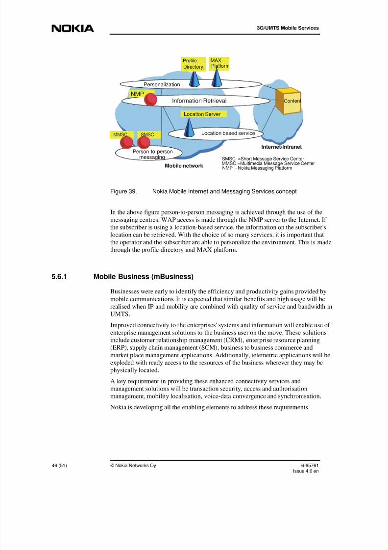
8/13/2019 UMTS Services and Applications
http://slidepdf.com/reader/full/umts-services-and-applications 46/51
3G/UMTS Mobile Services
46 (51) © Nokia Networks Oy 6-65761Issue 4.0 en
Mobile network
Internet/Intranet
Content
Person to personmessaging
MMSC SMSC
SMSC =Short Message Service CenterMMSC =Multimedia Message Service CenterNMP = Nokia Messaging Platform
Personalization
MAXPlatform
Profile
Directory
Location based service
Location Server
Information RetrievalNMP
Figure 39. Nokia Mobile Internet and Messaging Services concept
In the above figure person-to-person messaging is achieved through the use of the
messaging centres. WAP access is made through the NMP server to the Internet. Ifthe subscriber is using a location-based service, the information on the subscriber's
location can be retrieved. With the choice of so many services, it is important thatthe operator and the subscriber are able to personalize the environment. This is made
through the profile directory and MAX platform.
5.6.1 Mobile Business (mBusiness)
Businesses were early to identify the efficiency and productivity gains provided bymobile communications. It is expected that similar benefits and high usage will berealised when IP and mobility are combined with quality of service and bandwidth in
UMTS.
Improved connectivity to the enterprises' systems and information will enable use of
enterprise management solutions to the business user on the move. These solutionsinclude customer relationship management (CRM), enterprise resource planning
(ERP), supply chain management (SCM), business to business commerce and
market place management applications. Additionally, telemetric applications will be
exploded with ready access to the resources of the business wherever they may bephysically located.
A key requirement in providing these enhanced connectivity services and
management solutions will be transaction security, access and authorisationmanagement, mobility localisation, voice-data convergence and synchronisation.
Nokia is developing all the enabling elements to address these requirements.

8/13/2019 UMTS Services and Applications
http://slidepdf.com/reader/full/umts-services-and-applications 47/51

8/13/2019 UMTS Services and Applications
http://slidepdf.com/reader/full/umts-services-and-applications 48/51
3G/UMTS Mobile Services
48 (51) © Nokia Networks Oy 6-65761Issue 4.0 en
Multi Media Kiosk
Vending Machine
Loyalty cards
Local payments
Transportation
OnlineLocal
Auction
Music downloading
Online banking
Ticketing
Online payments
Application downloading
Figure 40. Examples of where mCommerce could be used

8/13/2019 UMTS Services and Applications
http://slidepdf.com/reader/full/umts-services-and-applications 49/51
Review questions
6-65761Issue 4.0 en
© Nokia Networks Oy 49 (51)
6 Review questions
Please take time and answer the following review questions:
1. Which of the following are UMTS services?
a. cs data services
b. Web browsing
c. SMS
d. speech call
e. VoIP call
f. voice mail service
2. Identify “operator specific services” (OSS):a. cell broadcast service
b. packet switched service
c. SIM application toolkit (SAT)
d. CAMEL
3. (U)SAT specifies open application programming interfaces between
a. SIM and ME
b. SIM and a remote application server
c. SIM and SCP
d. ME and RNC
4. WAP/WTA was developed to
a. support exclusively MexE
b. to design and program application locally on the ME
c. to allow interaction between the SCP and the ME
d. to support radio interface protocols.
5. The abbreviation OSA stands for Open Systems Architecture.
True o False o

8/13/2019 UMTS Services and Applications
http://slidepdf.com/reader/full/umts-services-and-applications 50/51
3G/UMTS Mobile Services
50 (51) © Nokia Networks Oy 6-65761Issue 4.0 en
6. Which of the following sentences best describes a bearer?
a. A traffic channel only for speech
b. A signalling connection between the core network and the radio access
c. A variable channel that can carry different types of data
d. A fixed-bit-rate data channel
7. VHE is the abbreviation for Virtual Home Environment. Which of the following
is, or will be, a characteristic of the VHE (more than one)?
a. Allows the subscribers to use their services whilst roaming.
b. The subscribers can customise their own environment.
c. It is the same as a SMSC (Short Message Service Centre).
d. VHE is possible because of CAMEL.
e. VHE is located within the HLR.
f. It is only possible in UMTS.
c.
8. Location Services
a. can be offered only in combination with a subscription to basictelecommunication services
b. are a prerequisite for roaming
c. used for determining the position of the mobile terminal
d. and Location Based Services have the same meaning
d.

8/13/2019 UMTS Services and Applications
http://slidepdf.com/reader/full/umts-services-and-applications 51/51
Review questions
Further information
The specifications give detailed information on how services should be implemented
into the network. The service classification of Release 2000 can be found fromSpecification 22.976. The below figure is taken directly from the specification and
identifies where to find information on the types of services that have been coveredin this module.
Toolkits:
CAMELMExE
SIM ATKOSA
LCS"Internet tools"
SoLSAetc...
Circuitteleservices
(22.003)
Telephony
FAXSMS
Valueadded
non-callrelatedservices
(e.g. eMail,MMS,
WWW, News,
etc…)
IPmultimediaservices
OtherBearer
servicesSMS,UUS,
USSDGPRS(22.060)
CircuitBearer
services(22.002)
Supplementary
services(22.004)
Figure 41. Service classification, taken from Specification 22.976
In addition to the bearer description in the above figure, for more information on theVHE, refer to 22.970. This gives the overview of the specification and is useful in
locating detailed information. For information on the wireless protocols of SAT andMExE, refer to the stage 1 (overview) specifications of 22.038 and 22.057
respectively.
If you are interested in finding out more information on the supplementary services,the stage 1 specifications can be found in the range starting from 22.072 until 22.097
inclusive. Stage 2 and stage 3 (implementation and technical realisation) can befound from the specifications, but the stage 1 should give you a start on how to find
the desired information.
Finally, if you wish to read more about the UMTS service principles and service
capabilities, then we recommend references to 22.101 and 22.105. At the time, thereis little literature in the general media about services. Remember to check the Nokia
web site (www.Nokia.com) for the latest information.