unclassified ad 4 04 461 · unclassified ad 4 04 461 mhe defense documentation center for...
TRANSCRIPT

UNCLASSIFIED
AD 4 04 461
Mhe
DEFENSE DOCUMENTATION CENTERFOR
SCIENTIFIC ,ikND TECHNICAL INFORMATION
CAMERON .AfATION. ALEXANDRIA. VIRGINIA
U NCLASSIFIED

NOTICE: When government or other drawings, speci-fications or other data are used for any purposeother than in connection with a definitely relatedgovernment procurement operation, the U. S.Government thereby incurs no responsibility, nor anyobligation vhatsoever; and the fact that the Govern-ment may have for=mlated, furnished, or in any waysupplied the said drawings, specifications, or otherdata is not to be regarded by implication or other-wise as in any manner licensing the holder or anyother person or corporation, or conveying any rightsor permission to manufacture, use or sell anypatented invention that may in any way be relatedthereto.

REPORT NO. 1192FEBRUARY 1963
HEAT TRANSFER, BARREL TEMPERATURES AND
THERMAL STRAINS iN GUNS
Ernest L. BannisterRichard N. JonesDonald W. Bagwell
*RDT & E Project No. IM01050IA004BALLISTIC RESEARCH LABORATORIES
ABERDEEN PROVING GROUND, MARYLAND

fAS'TJ\ AVAILIOILII'Y NO1TICE
stov may! 3'o O'0IlL 1lii 1 0 p,,: ot.' 11 i'01)O r t f romn AST1A.
f'±iridinv,_;L in ti i; (v.(r. ~r iioDL t-0 be coistracdF-., an official Dephtrnw',ii of' the Arff' position.

BALLISTIC RESEARCH LABORATORIES
REPORT NO. 1192
FEBRUARY 1963
HEAT TRANSFER, BARREL TEMPERATURES AND THERMAL STRAINS IN GUNS
Ernest L. BannisterRichard N. JonesDonald W. Bagwell
Interior Ballistics Laboratory
RDT & E Project No. lMOlO5OlAOO4
ABERDEEN PROVING GROUND, MARYLAND
BALLISTIC RESEARCH LABORATORIES IREPORT NO. 1192
ELBannister/RNJones/DWBagwell/jdkAberdeen Proving Ground, Md.February 1963
HEAT TRANSFM, BARREL TEMPERATURES AND THERMAL STRAINS IN GUNS
ABSTRACT
Data on temperature distribution and heat input in a 57mm gun during
firing are presented. These results are discussed and compared with
theoretical values obtained by using the Nordheim, Soodak and Nordheim method
of calculation.
5

TABLE, OF CONTENTS
Page
ABSTIRAC.O ,C . . . . . . . . . . . . . . . . . . . . . 3
I.* INJ O0lUCTION. . . .......................... * * 7
II. EXPERIMENTAL PROCEDURES. . . . . . . ., . .... .. . 7
III. DATA AND RESULTS . . . o. *, o o 9 , . . . ., * . a . 16
IV. COMPARISON WITH THE THEORY OF NORDHEIM, SOODAK, AND NORDHEIM . . . 23
ACKNOWLEDGMENT. ..... o . . ........ #...........so #. 37
REFERENCES . . .... . . . . .. . * - o - o s o o o s v o 38
APPENDIX A
I. SYMBOLS USED IN APPENDIX. . o . . . . . . . . . . . . . . . . . . . 40
II. ASSUMPTIONS .a . . • . . . o o * a * o s 9 o o a o . . . . . . 42
III. FLUX OF THE PROPELIAT GASES* .................. 4
IV. NORDHEIM, SOODAK, AND NORDKEIM (NSN) REDUCED BALLISTIC SYSTEM. .. 46
V. REDUCED EQUATIONS OF HEAT CONDUCTION . .......... .... 50
VI. THE CHOICE OF THE FRICTION FACTOR. o ...... . • , o s o 53
VII. THE CALCULATION OFTHE HEAT INPUT . . . .... ......... 54
RFEWENCES . . . . . . . . . . . . . . ........ 56
5
I. INTRODUCTION
Many text books on Interior Ballistics contain theories which permit the
calculation of heat transfer rates, barrel temperatures and thermal strains
in gun barrels. These theories are developments from the extant theories of
heat transfer in tubes or to flat plates and are valid strictly for fully
developed, steady flow. The situation in a gun barrel during operation of the
gun is by no means steady. The boundary layer is very thin and the surface
is not smooth. The validity of the theories and the accuracy of the derived
results are open to some question. There does not exist much published experi-
mental data by which one can evaluate the theories in question or arrive at
empirical correlations among the parameters of importance to the phenomena in
question.
The Ballistic Research Laboratories have for some years been interested
in the problem of the measurement and control of heat transfer in guns and
have made many firings on a laboratory scale in rather well instrumented 57mm
guns under various conditions of propellant type, projectile mass, muzzle
velocity, etc. Measurcments were made, not only of the usual pressure vs.
time and muzzle velocity, but also of external barrel surface temperatures,
internal bore surface temperatures and external barrel thermal strains, and
in some cases erosion rates. The temperature and strain measurements make it
possible to calculate the overall heat input and thermal dilatation coefficient
of the barrel. Comparison can also be made with the values calculated by the
extant theories and estimates made as to the accuracy and utility of the latter.
[L. EXPERIMENTAL PROCEDURES
The temperature of the external surface of the barrel was measurej with
gages Known asv RdF 2tikons. The;e gages; (manufactured by Arthur C. Ruge
Ajsociates, Inc., Hudson, hew llampi;hire) esLsentially are resistance ther-
mometers aind are very convenicint for the purpos e, and yield consistent results.
They are simil-,r in) nppenrance to cemunted ;train gages and are applied in a
similar manner. The model us,;ed is de:signated a: type PN-I and has a resistance
of' 50 ohms at (0 F. As, used in heat expuriments, the gage forms one arm of a
Wheatstone bridge circuit. When the gage is heated the resulting unbalance of
the bridge i.; indicated by the cui-rent in a iiaicroameter and is a measure of
the temperature ri.:e of the gage.

The following procedure was used to calibrate the PN-l gages. The
Wheatstone bridge circuits were all constructed with 0.1% precision resistors
of the same value. A precision decade resistor is substituted for the PN-l
gage, and with constant voltage in the bridge, the resistance is changed by
one ohm steps, and a plot of resistance vs. current on the microammeter is
made. Each bridge was calibrated in this manner, and the slopes were compared.
All of the bridges used were exactly alike. The PN-1 gage manufacturer supplies
a calibration chart showing resistance change as a function of temperature
change. Now if one of these gages is waterproofed and placed in a water bath
the temperature of the gage can be determined, and when it is connected into
one of the bridge circuits, the change in resistance as a function of temper-
ature can be measi,-red as a change in the current in the microammeter. From
this, a plot of temperature vs. current can be made with the slope being the
gage calibration factor to be used with that particular bridge. Since all of
the bridges are alike, only one gage need be completely calibrated.
To protect the gages from the effects of changes in temperature of the
environment they were covered with a layer of plastic foam fastened down with
several layers of electrician's tape.
The thermal strain measurements were made with Baldwin Southwark SR-4
cemented on strain gages, type CIO, 1000-ohm resistance. They were first
applied in the usual way using Duco cement. It was found, however, that their
indications were quite variable from round to round. The thermal strains are
very small and are preceded by relatively very large strains due to the gas
pressure and the pressure due to the rotating band. It is probable that this
large pressure causes some slight slippage of' the gage which affects the sub-
sequent measurements of the small thermal strain. It appeared to be necessary
to cement the gages more securely to the barrel. This was done in the following
way. A thin layer of epoxy resin (Araldite GN 502 manufactured by Ciba Co.,Inc.,
Kimberton, Pa.) was applied and the gage pressed firmly into the cemert until
any excess was removed along with any air bubbles. The gage was then covered
with a piece of waxed paper upon which was placed a piece of sponge rubber.
This assembly was bound tightly to the gun barrel with several turns of No. 14
wire and was allowed to cure for several days under an infrared lamp. After
8

curing was completed, the gage was coated with several layers of insulating
varnish. Finally, as a protection, several layers of electrician's tape were
wrapped over the gages. Gages applied in this manner gave consistent readings
for several hundred rounds. Two active gages were used in a Wheatstone bridge
circuit so as to enhance the signal.
A typical record is shown in Figure 1. The signal from the gage was
displayed on a cathode ray oscilloscope and photographed with a Polaroid Land
Camera. The sweep time is 1.3 sec/cm measured on the record. The record shows
that the full strain is reached in about 0.4 seconds and is effectively constant
as the heat diffuses through the barrel. This is to be expected since the strain
depends on the total heat input and is independent of its distribution. The"hash" on the early part of the record is due to the shock of firing and the hash
near the center of the record occurs when the gun comes back into battery. The
dots at either end of the record are calibration steps taken at the beginning
and end of the oycle. Each step is due to a voltage change of 0.4 millivolts.
Usually the strains were measured circumferentially. In some cases longi-
tudinal strains were measured simultaneously but were found to be equal to the
circumferential strains.
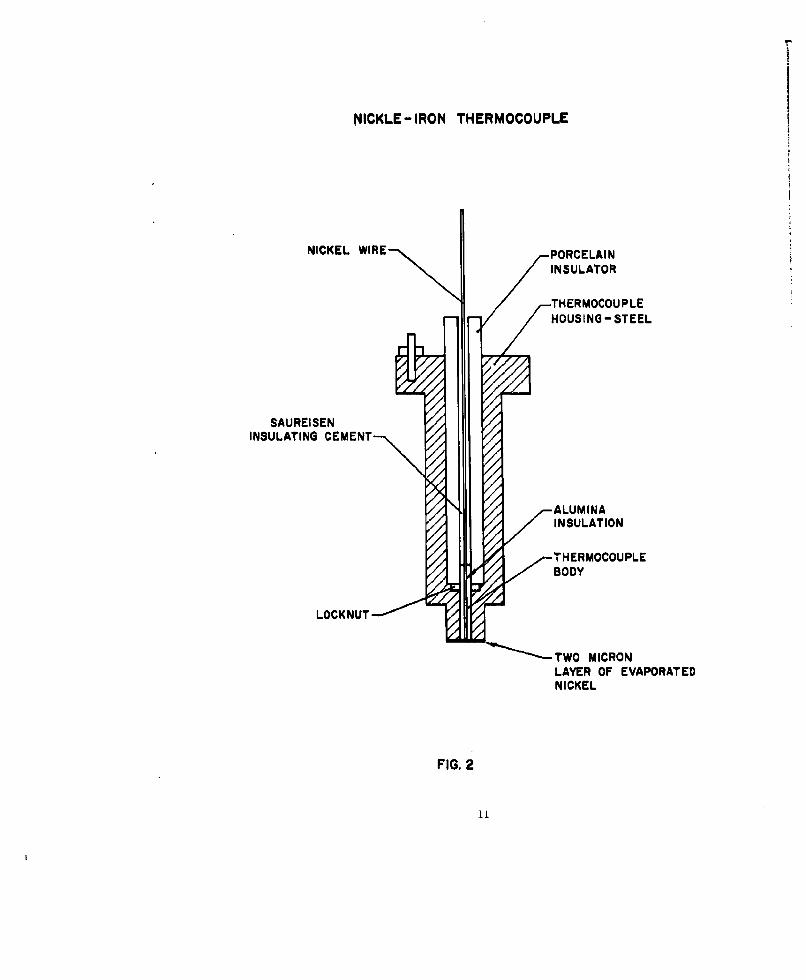
The internal or bore surface temperature measurements were made with surface
thermccouples of the Hackemann type. These thermocouples were first designed by
P. Hackemann in Germany during World War II and have been extensively used andi.-2
are described in several references. Several models were used in the work
reported here. The earlier ones were supplied by the Midwest Research Institute,
Kansas City, Missouri. Subsequently others were fabricated at the BRL using
essentially the same techniques as were used by Midwest. The main features of
this model are shown in Figure 2. The thermojunction is the interface between
the nickel plate and the steel base. This is essentially a Ni-Fe couple. The
temperature is measured a few microns (the thickness of the plate) below the
actual surface. The average thickness of the plate on the couples used was
two microns. Since the Junction has csscntially zero heat uapauity, the
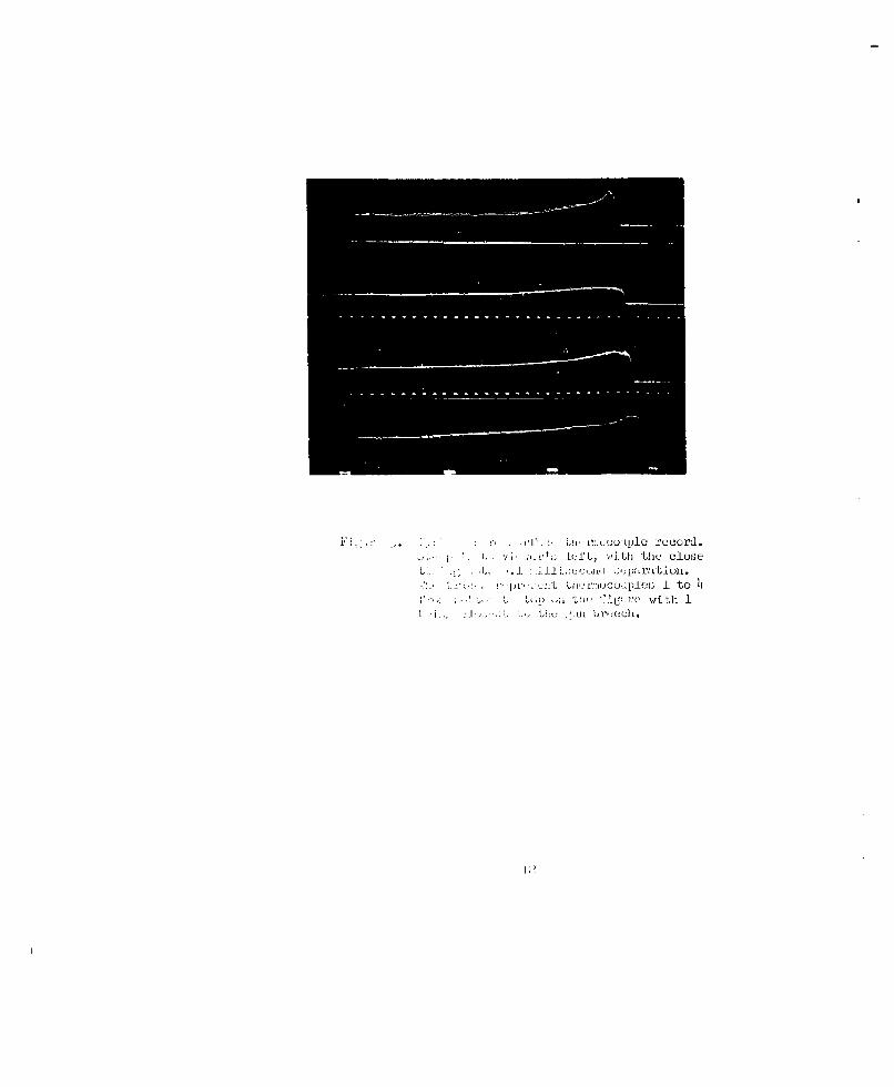
response of the couple is very rapid. A typical record is shown in Figure 3.
9

Jigirt 1.. ',[, S., , c'i. The Oscilloscope SweepJ,\;L'."i th, Vievewrs Right
I-
NICKLE -IRON THERMOCOUPLE
NICKEL WIRE-,, PORCELAININSULATOR
TH4ERMOCOU PLEHOUSING -STEEL
SAUREISENINSULATING
CEMENT -,,
ALUMINA
THERMOCOUPLE
LOOKN T - 0' 'q TWOMICRON
LAYER OF EVAPORATEDNICKEL
FIG. 2
FL - utlo record.'2L( I t L , ./i the close
* L Lw '± u-t -ei: 1. to bi* ~ ~ h L C' L[tre with 1

The four traces are from four thermocouples at different positions along the
barrel. Timing marks also appear on the record so that the variation of temper-
ature with time can be followed. The record shows that in this case the maximum
temperature is reached in about 100 microseconds.
Unfortunately, these thermocouples are very fragile and must be renewed
frequently if conditions are severe as they were in the work described here.
Considerable effort was expended in trying to improve their ruggedness, particu-
larly in the matter of adhesion of the plate. Although improvement was attained
they remained too fragile for extensive use under the severe conditions to which
they were subjected. The thermocouples were mounted in plugs which could be
screwed into the barrel in the desired locations until they made contact with a
specially designed instrument inserted down the bore. The contact was indicated
by the completion of an electrical circuit. The thermocouple was then retracted
three turns of the plug (about 3.8mm). It was observec that the lack of close
match between the surface of the thermocouple and the bore did not alter the
measured temperature significantly. Such behavior has also been reported in
the literature by other users of similar thermocouples.
The model shown in Figure 2 was the most rugged and effective of those
tested. The nickel plate was deposited with the thermocouple element mounted
in the plug so that the plate covers rot only the thermo element but also the
full surface of the plug. In fabrication, the entire surface to be plated was
ground and polished on a metallurgical polishing wheel, then cleaned with
alcohol. The unit was then mounted in the evaporator and heated by a specially
designed furnace to a temperature of 700 to 7500F. The surface was further
cleaned by an electric discharge and then the plate deposited while the thermo-
couple element was still hot. The apparatus was so designed that six units
could be fabricated simultaneously. The general procedures for determining
plate thickness were those given in Reference 5. In some cases the thickness
of the plate was checked by microccopic examination and found to agree with
the predicted thickness.
Part of the improvement of the ruggedness of these thermo elements may be
due to the fact that the plate extends over the end surface of the housing as
well as the end of the thermo element itself. The plate is continuous and the
larger area and circumference may make it more difficult for the gas to remove
the plate.
15

Because of the difficulty in keeping the plate in place when these
thermocouples are used in guns,it has been the practice in several laboratories
to establish and maintain the thermocouple operation by simply abrading the
surface by filing or rubbing on fine abrasive paper instead of plating. Enough
metal is swaged across the gap between the nickel wire and the steel tube to
make the Junction. This technique was used in this work also, but, although
such junctions are very simple to produce (and will successfully record temper-
ature and are often more durable than plated Junctions), the results of a large
number of firings showed that the recorded maximum temperatures are much more
variable than those produced by the plated thermocouples. Their use was, there-
fore, not continued.
In all, four different 37mm gun tubes (Model M-3) were instrumented. Two
had the rifling removed for another program which made it simpler to mount the
thermocouples as it obviated the problem of matching the thermocouple with the
bore surface. For the earlier work only one station was provided but later
five stations were instrumented on three of the tubes. Only one of these had
provisions for employing the bore surface thermocouples. The locations of the
different instrumentation are given in Table I. Chamber pressure also was
recorded by a gage located live inches from the breech face. Muzzle velocities
were measured by velocity coils in most cases but for some firings by lumiline
screens.
Firings were made with M-i d M-2 propellants and the charges were
adjusted to several velocity levels. In some cases mixtures of M-1 and M-2
were used to study the aftect of the propellant gas temperature upon the heat
input and barrel temperatures. In these cases the lots of propellants used
were such that the burning times were approximately the same. It was not
possible to make the times equal using the available lots (standard production
lots).

TABLE I
DISTANCES OF INSTRUMENTATION FROM THE BREEH FACE
(Inches)
Tube No. Instrumentation S T A T I 0 N S
1 2 3 4 5
1099(1 PN-l and Strain Gages 22-3/4Thermocouple 17-3/4
109974 PN-l and Strain Gages 20-1/4 29-1/4 37-1/4 51-3/4 64-1/4
Thermocouples 16-1/4 23-1/4 32-1/4 58-1/4 82-1/4
97551 PN-1 and Strain Gages 18 30 46 59 72
120023 PN-1 and Strain Gages 18 30 46 59 72
15

111. DATA AND PESULTS
The data and derived results are given in Table It. The column headings
are in general self-explanatory. The values recorded for the measured quanti-
ties are average values; in most cases for numerous firings and, in all cases,
for not less than six. The muzzle velocities are nominal values rounded off
from the average values and are presented to classify the firings.
The easiest to measure and the most accurately determined quantity is the
external barrel temperature rise. On firing, the indicator (the microameter)
rapidly reaches a maximum value and then slowly declines as the barrel cools.
The rise time is about five seconds from the time the heat pulse reaches the
outer surface and the rate of cooling is about 0.10 per second. The section of
the barrel on which the gage is mounted and the gage itself are well insulated
from the surroundings. Also the rise in temperature is never more than 50C.
It was therefore assumed that the temperature gradients through the barrel wall
were small, as were the heat losses, and that the gage recorded what was, in
effect, the average temperature rise produced by the amount of heat supplied.
From the density and specific heat of the steel, it is possible to estimate the
total heat input per round. These estimates are given in Table II, the values
of the specific heat and density are those given in Metals Handbook3 for the
type of steel used for the barrels.
A measurement of the temperature rise and the simultaneous strain allows
a calculation of the thermal dilatation coefficient of the barrel. The strains
are much less well determined than the rises in temperature. The precision,
estimated from the average deviation from the average values is, for the temper-
ature rise, about 5 per cent, and for the strains, about 15 per cent. The
averge estimated dilatation coefficient for the barrels is considerably higher
than t6 t (about 1.1 x lO-5/C) given in the Metals Handbook for barrel steels.
Assuming that the strains are properly measured, this may be due to the fact
that the measured temperature rise is too small because of thermal gradients
to the surface, or the thermal expansion of the barrel may depend on the method
of fabrifttion. That the latter alternative may be valid is supported by infor-
mation from Watertown Arsenal , which states that the thermal dilatation coef-
ficient of similar barrels was measured to be about 1.5 x lO 5/0C. This value
16

TARL U
CONSOLDATEDATA AND DRUMM 2EWS OF TYPIOAL FmINOS
itassle barge Raia Baarel Total Eat Diatation DoraTube No, Station Velocity N-1 M-9 Temp. Tap.Eise Input Strain Coeff. Tap.
ft/tle p i oK 0V Cal.lee no 5 f0
5/°C O
109961 1 1800 130 0 2480 1.44 6.31 2.82 195 65810 21 2670 1.51 6.61 2.91 1.93 61078 4.1 28.5 1.62 7.10 3.07 1.90 73452 61 3055 1.69 7.40 3.07 1.82 71826 81 3280 1.90 8.1. 3.31 1.76 4510 101 351o 1.9 8.50 3.57 1.74 766
109961 1 2400 218 0 2480 2.31 10.1 h.20 1.82 587175 33 2650 2,26 9.90 4.26 i.88 56h131 66 2835 2.53 11.1 h..62 1.83 69387 99 3015 2,59 11.3 h.65 1.80 618.3 132 3270 2,71 11.9 h.85 1.79 686o 165 35.0 3.10 13.6 5.38 1.7 774
10997 1 2100 0 165 354o 3.30 12.8 4.15 1.35 8102 2.99 1o.8 3.95 1.35 68033.16 10.3 4.60 I.5 628h 4.61 8.90 6.59 1.1 1315 6.h5 8.77 9.75 1.51 --
1 21.00 g1B 0 21.8 2.1.2 9.37 3.93 1.62 631.2 2.22 7.99 3.18 1.57 6703 2.36 7.74 3.81 1.61 1704 3.45 6.62 6.70 1.95 3255 4.86 6.61 9.10 1.87 --
97551 1 2310 215 0 24180 12.72 9.65 6.54 6.65 6.6
97551 1 5000 o 220 51o 15.92 13.23 8.66h 8. h65 9.24.
120225 1 3700 0 235 5h5o 15.72 12.73 10.11 12.05 10.9
97551 1 2100 255 C 2180 12. .2 9.553 6.721 6.975 7.17
97551 1 2700 190 50 2710 1.82 10.23 7.00h 7.355 7.35
97551 1 2700 125 100 2955 14.2 10.63 7.17h 7.805 7.47
97551 1 2700 60 150 5210 15.023 7.771 8.0o5 7.88
9T551 1 2700 0 200 351.0 16.025 8.881 8.905 9.17
17

was not determined from the thermal strains due to firing but rather by uni-
formly heating the tubes. The BRL values are still greater than the Watertown
values, on the average, so that there still may be some discrepancy in the
assumption that the measured temperature rise is equal to the average temper-
ature through the barrel wall.
The total heat input per round falls rapidly with distance down the barrel
as shown in Figures 4 and 5. The data are not extensive enough to determine
the functional dependence accurately. It is probable, that as the measurements
are taken closer to the muzzle, the functional dependence will change because
as the muzzle is approached the heating is more and more that due to the gas
flowing out at the muzzle as the tube empties, after exit of the projectile.
After exit, the character of the gas flow is different and depends on different
parameters. The graphs show that the heat input reaches a minimum at about
six-tenths of the travel and subsequently rises somewhat toward the muzzle.
In all cases for constant ballistics (i.e. constant peak pressure and
muzzle velocity) for which measurements were made the total heat input turns
out to follow closely a linear dependence on the adiabatic flame temperature
of the propellant. The data for one series (muzzle velocity 2700 ft/sec) are
plotted in Figure 6. The figure shows also that the slopes of the graph for
the different stations are equal within the precision of the data. The same
is true for data taken at 1800 ft/sec. In this case, only one station was
instrumented. The dependence on flame temperature is not very strong. This
is due to the fact that as a cooler propellant is used it is necessary to use
a larger charge. This increases the mean density of the gas which increases
the heat transfer coefficient, thereby tending to compensate for the decreased
gas temperature.
The bore surface temperatures indicated by the thermocouples are subject
to large round to round variation and to obtain consistency in the readings an
average over a number of firings must be taken. Figure 7 is a plot of the
average maximum bore surface temperature for four of the five stations. It
was found to be not possible to make measurements at the fifth station. The
thermocouples were too fragilc to withstand the shock of firing. The plotted
points are averaged over sixteen rounds and, except for station 2 for M-1
a8
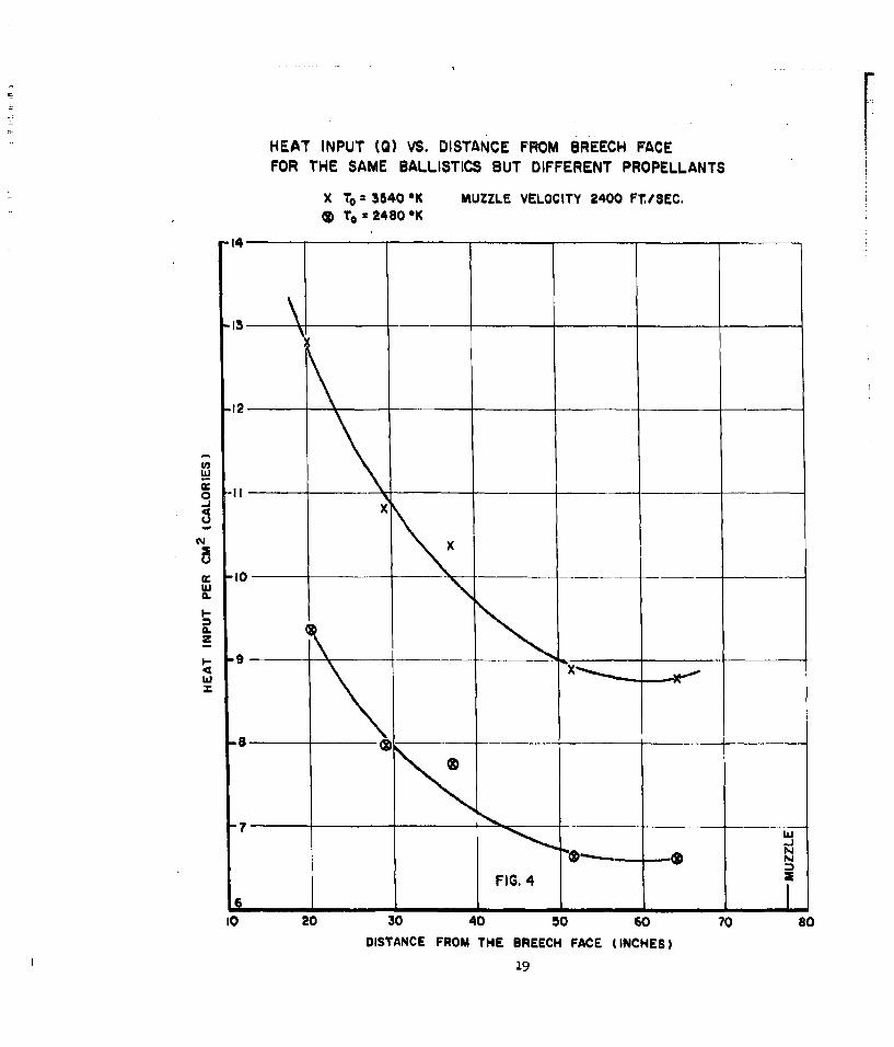
HEAT INPUT (0) VS. DISTANCE FROM BREECH FACE FFOR THE SAME BALLISTICS BUT DIFFERENT PROPELLANTS
X T: 3540 OK MUZZLE VELOCITY 2400 FTI.SEC.To T24130OK
14-
13
-2
Ld
x
E 10
-9
0.
FIG 4;
161
102 04 06 0s
DITNEFRMTEBREHFCE(NHS
7 LU

HEAT INPUT (0) VS. DISTANCE FROM THE BREECH FACEFOR SAME BALLISTICS BUT FOR DIFFERENT PROPELLANTS
MUZZLE VELOCITY -2700 FT/SEC.To- 2480* X
27080 02956* Il3240* 03540' A
-16-
L
cc 2 -- FIG. 5(L
-1
Lu
8
.................. X
10 20 30 40 50 60 70DISTANCE FROM THE BREECH FACE (INCHES)
20

HEAT INPUT (0) vs. PROPELLANT FLAME TEMPERATUREFOR SAME BALLISTICS
MUZZLE VELOCITY 2700 FT/SEC.
is X
CK 12__ _ _ __ _ _0-a
w
I-
z.CS
I-.c
30
4_ __ FIG. 6 -_5___
2'2400 2600 2800 3000 3200 3400 3600 3800
PROPELLANT FLAME TEMPERATURE *K
21

LUxz
xx
0LL~
L)z0
LUU
LL w
fnU
w- N ---II 0
ME z
L<U
It -J Ij0
a)U
0. 00 8
LUl31 8 VO 3 ovjn uewiiv2:'o

propellant, they follow a consistent pattern. The data for the exceptional
point have been checked. The rounds from which this point was derived were
not all fired consecutively. They were distributed over a period of more
than a year and any one thermocouple rarely lasted more than five zmunds. It
would seem that the deviation of the point from its appropriate value is
statistical. The precision, as measured by the average deviation from the
mean value, averages about +150 C for the different stations so that the point
is not outside the indicated precision of the data. The results indicate that
one should use these thermocouples for bore surface temperature measurements
wit, considerable discretion.
It is the opinion of the writers that the wide fluctuations in the thermo-
couple indications are real. There is considerable contamination of the thermo-
couples due to deposits from the propellant gases and also copper from the
rotating band. It is also doubtful that a uniform surface temperature exists.
The gas is not all at the same temperature. The firing cycle is so short and
the mixing process relatively so slow, that the thermocouple may sense quite
different maximum temperatures from round to round. The roughness of the
surface, which varies from round to round, will also influence the rate of heat
transfer locally, so that, in effect, a uniform surface temperature does not
exist.
The data taken for the mixed propellants M-1 and M-2 bear out these ideas.
The thermocouple readings do not follow a consistent pattern as do the data on
total heat input. In this case, the variations in the gas temperature during
firing will be much more drastic than for a single propellant and one would
expect the data to show wider and more i'regular fluctuations than for a single
propellant.
IV. COMPARISON WITH THE THEORY OF NORDHEIM, SOOnAK AND NORDHEIM*6
It has been po.Lnted out earlier that the extant theories of gun barrel
heating assume that the existing theories of heat transfer by forced convection
between a solid boundary and a steady turbulent fluid flow can be applied to
In this report abbreviated NSN
23

the case of the gun. The problem is to calculate the rate of heat transfer
to the barrel wall as a function of the interior ballistic parameters which
specifies the boundary condition on the solution of the Fourier Heat Conduction
equation. It is assumed that the rate of heat transfer H(t) is given by:
H(t) = h( w - V
where T is the gas temperature in the gas away from the wall, T is the wallg w
temperature and "h" a heat transfer coefficient. In the case of the gun, h,
T and Tw are all functions of the time but it is assumed that equation (1)
is "quasi steady" that is, it holds over each small interval of the integration.
There exists an extensive literature on the specification of h. Nordheim,
et al , adopt a very simple formula for h, namely:
h= Cp V (2)
where C is the specific heat of the gas at constant pressure, p the density
of gas and V its velocity. The quantity X, which they call the friction factor,
is, in their theory, essentially a "fudge" factor to be determined experimentally.
Corner presents an estimation of h from boundary layer theory but finds that
the results have to be corrected empirically in any case.
The usefulness of the theory will depend, obviously on how well X can be
estimated for a particular situation. This will depend on a sufficiently
extensive accumulation of experimental determinations of X, for a wide variety
of cases so that, for a particular case, a reasonably reliable value of X canbe specified. Unfortunately, at this time, very few data have been published
which permits an adequate evaluation.
A rather detailed discussion of NSN theory as applied to guns is included
in an attached appendix. NON solve the Fourier Equation in one dimension, that
is, they assume that the curvature of the bore can be neglected. Following
their procedure we have coded the prublem for machine computation. The values
of X were adjusted to make the theoretical values of Q agree with the measured
values to within the precision of the latter. These values of X, as well as
24

the measured values of Q, for a series of firings at 2400 ft/see are plotted
in Figure 8 for both M-1 and M-2 propellant. They decline steadily with
distance down the bore but not so rapidly as the measured values of Q. Near
the muzzle, they tend to decline less rapidly than does 0. This effect may
be real in part. The bore is more eroded toward the breech and muzzle and
one would expect X to be larger for a rough surface. X does not depend on
the surface condition only however, as is evident from the treatment of Corner
given in Reference 7.
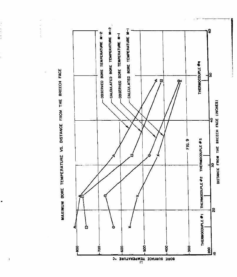
From Figure 8, one can estimate the values of X at the positions of the
thermocouples and calculate the bore surface temperatures at these locations
for comparison with experiment. When this is done, it is found that the
maximum bore surface temperatures calculated are, in general, quite close to
the measured values. In no case is the difference greater than the estimated
error in the measured values and, in most cases, it is considerably less thLa
this. The values are plotted in Figure 9.
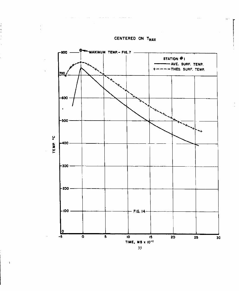
The average observed bore surface temperature is plotted as a function
of time along with the calculated values for some typical cases in Figures
10 through 17. The agreement is satisfactory since the divergencies are not
greater than the estimated precision of the observations.
It should be noted thot the maximum temperature plotted in Figures 10
through 17 does not correspond exactly with the maximus temperature shown in
Figure 7. The reason for this is the following: The temperatures determinud
by the thermocouples were recorded by means of a 55mim moving film oscilloscope
recorder. After the records were developed, the peak temperature only was
read. The records were then stored in a record file for future reference.
Sometime during storage about one half of the total records, some 15 roundL,
wore either lost or destroyed. Hence, when further study of the records was
started, the average values of the temperatures were different than those
shown in Figure 7. Unfortunately, there was no requirement to determine
temperature as a function of time when the firings were first made.
However, in view of the rather wide scatter in the bore surface temper-
ature as measured by the thermocouples, it is the opinion of the authors that
data as shown in Figure 7 and Figures 10 through 17 are compatible and are of
considerable value.
25

TI
U.U
w
MJ_- _ 2 - 0
0 LU
220 LLJ 0
LL 0
40 ou2zL
El 0a 0 L
00 L
LL
N
1200
(S3I8O1VO) 03AA3SSO- (01 iLfdNI .1W3H
cc8
I-- w
o w o___ -0
U. 0m U
0 0
ww
00
4 L
Fn00
x ~LL0.
w
LiJ
00
J 1
oo3n4t~l3. 0~n toU2
In Figures 10 through 17 the solid line indicates the average bore
surface temperature as measured by the thermocouples, and the dashea line,
the surface temperatures as computed by NSN theory using a value of X esti-
mated from Figure 8. The time scales were adjusted arbitrarily so that
maximum temperature occurred at zero time.
In view of the difficulty of making accurate bore temperature measure-
ments, it would appear from tho present work that one could make external
barrel temperature measurements and use the value of X (adjusted to match theexternal temperature) to calculate barrel temperature distribution. This
would hot require the drilling of holes in the barrel and would probably give
as reliable a determination of the barrel temperature distribution as one could
obtain from thermocouples.
28

CENTERED ON TMAX
8900-
AVE. SURF. TEMP.I70 +- -- -THEO. SURF. TEMP.
MAXIMUM TEMPERATURE
EMA FIG. 7
-600
+/+
40
w
500 _ _
-200-----
-100 FIG 10 __
-5 0 5 10 15 20 25 30
TIME, MS x 10-1
29

CENTERED ON TMAX
-600-STATION #2
AVE. SURF. TEMP.
+ .---- THEO. SURF. TEMP,
MAXIMUM TEMPERATUREFIG.?
-600.
-100--. +,.- +"00/
* /
3 00
-200
-100 FIG. 11
-5 0 5 10 15 20 25 30
TIME, MS x 10-1
30

CENTERED ON TMAX
8600-
700-STATION #3
- AVE. SURF. TEMP+---- THEO. SURF. TEMP.
_600--
500 MAX(IMUM TEMPERATURE -
_300
200-
-100 FIG. 12 -
0 1_ _ _ _ _
-5 0 5 10 15 20 2TIME, MS 10-

CENTERED ON TMAX
6800 -
.700--
-600-_ _ _ _ _ _ _ _
-500 --- _ _ _
STATION *4- AVE. SURF, TEMP.
+----THEO. SURF. TEMP.
S400---
MAXIMUM TEMPERATURE
- ~FIG.3 7
-10 -5 0 510 15 20TIME, MS x 10-1
CENTERED ON TMAX
coo - MAXIMUM TEMR- FIG.?
I STATION #I-A E. SURF. TEMP,
70 - -THEOL SURF. TEMP.
_500-
040
*300-
200-
100 - FIG. 14-
-5 0 5 10 I5 20 25 30TIME, MS x 10-1

CENTERED ON T MAX
700 .MAXIMUM TEMPERATURE FIG.7 STATION
o f - AVE. SURF. TEMP4( +---THEO. SURF. TEMP, |
- oo . 4--+
-500 +j
-4 0 "" " - . ....
-200
-100 FIG. 15-
-0
-10 -5 0 50 15 20 25
TIME, MS 1 I0- 1
)4

CENTERED ON TMAX
Too-
MAXIMUM TEMPERATURE0' FIG.?7
600STATION *3
AVE, SURF. TEMP.
00, +--- THEO. SURF. TEMP
-500-
300-
100 -FIG. 16 -
-10 -5 0 5 10 15 20 25
TIME, MS it 10-

CENTERED ON TMX
-800 ____
_700-
600 -- -- ---- ~ _ ___ _____ ____
STATION *4AVE. SURF TEMP.
+--THEO, SURF. TEMP.
500 -----. ---
MAXIMUM TEMPERATUREU FIG.?7
00
++
200 - -_ _ _
100 - - - FIG. 17 - _ _ _ _
0 ______ _ _ _ _ _ _____ _____
-10 -5 0 10 15 20 2TIME, MS 1 0-'
56

ACOWLEDI
A number of the experimental procedures and techniques used in this
program were developed by military personnel assigned to the Interior Ballistics
Laboratory. In addition, large amounts of the data were taken by military
members of the Laboratory. With this in mind, the authors wish to express
their appreciation of the support and cooperation given by Lt. David Wel.s,
Pfc. Norbert Edlebach and Pfc. Donald E. Benz during their assignment to
the research program. The work of Mr. Homer Murray in developing the technique
for improving the nickel plating of the thermocouples, and the work of
Mr. Fredrick McIntosh of the Ballistic Research Laboratories' Computing
Laboratory in developing and programming a system for machine computation of
the heat input data is greatly appreciated.
ERN'EST L. BANISTER~
B.N. JO S
DONALD W. BAGWELL '
37
RpEBENCES
1. Hfackemann, P. A Method for the Measurement of Rapidly Changing SurfaceTemperatures and its Application to Bores of Guns; Aircraft ResearchCenter, Hermann Goering, Brunswick Germany, 27 January 1941 (In German).
2. Midwest Research Institute, Kansas City, Missouri.
3. The Metals Handbook, 1948 Edition, The American Society of Metals,Cleveland, Ohio.
4. Grazdis, M.B. and Kosting, P.R. Dilation of Centrifugal Castings, 0414,
C696, C769; Report No. 314/22; 22 June 1937, Watertown Arsenal, Watertown,Mass,
5. Strong, J. Procedures in Experimental Physics, Prentice-Hall, Inc. (1938)
6. Nordheirn, L.W., Soodak, H., and Norctleln, G.; Thermal Effects ofPropellant Gases Ln Erosion Vents and in Guns, NDRC Report No. A262.
7. Corner, J. Theory of the Interior Ballistics of Guns, John Wiley & Sons
(1950).
38

APPENDX A
NORD1HIIM, SOODAK, ANTD liORflHfl T1WOHY OF IMAT TflANSrER ill~ GUNS

1. 87MB USED fI THIS APPENDIX
SMOL UNIT 33ITION
F (Oam /Seca)[ nRT ],the "impetus" or force
of the propellant.
n mole/es Niumber of moles of propellant gas
formed per gram of propellant.
R erg/*K Gas constant
T 0 OKAdiabatic Gas Temperature
Y True ratio of specific heat C p/C
Effective ratio of specific heatswhich corrects for heat loss
C PCal/v? C Specific heat at constant pressure
CvCal/g 0 C Specific heat at constant volume
p gM/CM3 Density of Solid Propellant
Gun Constants
M grams True mass of projectile
m grams Effective Mass of Projectile
C gr'ams I~4ss of Propellant Charge
usCm Volume of the gun from the breech
to a specified point s
A Cn? Cross sectional area of the bore
x Cm [U./A] Coordinate along the bore
Y Cm X1, .C/App Reduced coordinateSalong the bore
40o

5D OL ~ EFMTON
Ballistic Notations
V cm/seo [dxIdt -dy/dtj Projectile Velocity
2es/ 2 Pressure
14(t) SM Mass of Propellant burned upto twice t
B cm2 sec/m Burning constant
W cm Web thickness of propellant
Reduced Ballistic Quantities
J I~~M/0 I The ratio of poetleffective mass to chargemass
[C/v C/Ax ° Density of loading
c/sec r CB F Reduced b"u-ning constantL 7- K J7 -I F 2 Burning parameter
Ym/y- Reduced length of gun
U D
Y (l -.)]IP
413

II. ABBUMPTIONS - iIn order to apply the theory of heat transfer to guns, the following
assumptions are necessary:
1. The equation of state for the propellant gases is assumed to be
a simplified Van der Waals equation,
where P is the pressure, p the gas density, ij the covolume, R the gas constant,
n the number of moles per gram of propellant gas, and T the absolute tempera-
ture of the propellant gas, in degrees of Kelvin. The "force" of the propellant
gas is determined by
F = nRT (2)
where T is the adiabatic flame temperature. The specific heat Cp and Cv
and n;; i' ratio 7 are asserLed to be independent of temperature.
2. The steady state formiula,
It h (8 - e) (>)
holds for the unstuady oitutation in a gn, that is:
11(t) - h(t) 1 0 8(t) - BV(t)l 4
where G is the temperature relative to some initial temperature.
3. That the heat transfer coefficient h(t), is given by
H(t) -- C (P) (t) (5)
which expresses the heat transfer in terms of the mean specific flux (Pv) of
the gas, the specific heat C and the hydrodynamic factor X. This factor ispcalled the Fanning Coefficient in the literature, and is a dimensionless
constant that connects the pressure loss dp/dx along a pipe due to friction
with the dynamic pressure in the fluid according to the formula
4~2
1 dpro / %,u6
where r is the o called hydraulic radius, that is, the cross sectional
area of the pipe divided by one half of its circumference. However, in the
ease of a gun, X is essentially a "fudge" factor introduced to account for
the differences in heat transfer due to undetermined roughnesses on the sur-
face of the gun bore. A method for determining a value of X from heat input
data is discussed in the body of this report.
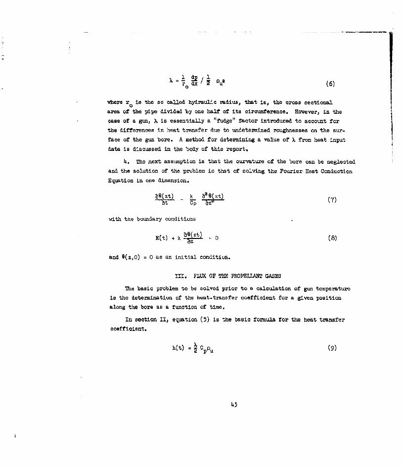
4. The next assumption is that the curvature of the bore can be neglected
and the solution of the problem is that of solving the Fourier Heat Conduction
Equation in one dimension.
Se(zt) k b--zt) (7)6t TCo 77z
with the boundary conditions
H(t) + k 2Zt = 0 (8)
and e(z,O) = 0 as an initial condition.
III, FLUX OF THE PROPELLANT GASES
The basic problem to be solved prior to a calculation of gun temperature
is the determination of the heat-transfer coefficient for a given position
along the bore as a function of time.
In section II, equation (5) is the basic formula for the heat transfer
coefficient.
h~t) = C (9)
43
Where PU is the specific flux of the Propellant -gazs, the
friotan tatox . is a constant for a partioular gun, an& C is the constantp
specific beat of the propellant gas. It is assumed that the unburned
propellant does not contribute measurably to the heat transfer.
Let us assume that the density of the propellant gases remain constant
throughout the whole gun. However, the flux, and with it, the heat transfer
will depend on the distribution of the unburned propellant during the
firing. Therefore, to describe the distribution, we introduce a form
function G(x t) that gives the fraction of unburned propellant between the
breechblock and the point x in the gun. While G may be a function of x
and time, it also must satisfy the following conditions
[G] ,s= 0, [G] Y- = x 1, (10)
where x is the coordinate of the base of the projectile, the fractional
density of the solid at x will be B- .aS
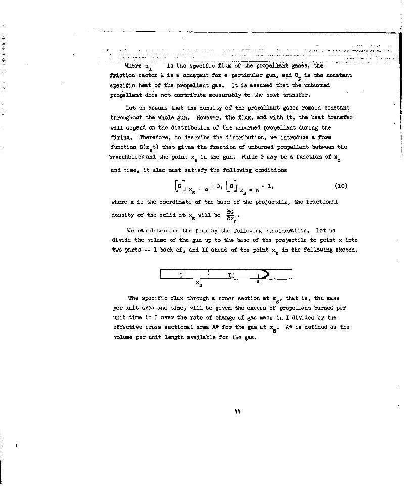
We can determine the flux by the following consideration. Let us
divide the volume of the gun up to the base of the projectile to point x into
two parts -- I back of, and II ahead of the point xs in the following sketch.
TI Dx x
The specific flux through a croas section at x that is, the mass
per unit area and time, will be given the excess of propellant burned per
unit time in I over the rate of change of gas raass in I divided by the
effective cross sectional area A* for the gas at xs . A* is defined as the
volume per unit length available for the gas.
4

By definition of G, the amount of propellant burned in T per unit time
is GdN/dt, where N is the amount of prope:Uant burned as a function of t;
the total mass of gas in I equals its density N/[Ax-(C-N)/P] , times the
available volume, Ax. - G(C-N/p . This expression is obtained by subtracting
the space occupied by the propellant in I from the volume in 1. We obtain
thus
iA* G E L d N Ax. -G(C-N)/p (11dN d dG 7-cIP
which with G 2H = L (GN) - N L- can also be written asdt dt d
a A(Gxx - ) diA* = N N -N--. (12)
Since the effective cross sectional area is defined as the volume per
unit length available for the gas, that is the true volume per unit length
minus the volume of solid propellant per unit length, we have
A* =A -[(C-N)/,,L ] A (~ dOR U (13)
These formulas allow us to write down the flux and thus the heat transfer
coefficient under any assumption regarding the distribution of the unburned
propellant if the ballistics are known; that is, if we have the functional
dependence of x and N on the time t.
We shall consider only the assumption that the unburned propellant is
always equally distributed over the whole available space. In this case G(a)
is the ratio of the volume I to the total volume, or
x d
G(a) = da ;2. (14)
45

Using equations (14) and (13) in (12) ve obtain
W N a xN'ak-)p x T7~x-N)/P"I
This expression can be directly interpreted as the density of the gas
N/EAx - (C-N)/P times a local velocity that stands in the ratio xa/X to
the velocity of the projectile.
IV. NORDHEIM, SOODAK, AND NORDHE324 (NSN) REDUCED BALLISTIC SYSBTE
The calculation of bore temperature and heat transfer for a gun becomes
the problem of integration of the Fourier equation as soon as a definite
ballistic system has been developed and definite values have been assigned
to the parameters involved - e.g., the friction factor, and the thermal
constant of the steel. Since some of the gun parameters are uncertain, it
would be rather impractical to solve the problem of gun heating and temperature
by treating each gun individually, that is, working out a separate ballistic
system for each gun, and then solving the heat conduction equation under all
possible assumptions in regard to the parameter concerned.
In order to get around this situation, it is desirable to use a slightly
simplified ballistic system in which similarity relations can be used to
reduce the number of necessary integrations. This becomes possible because
the ballistic curves, (velocity - travel - pressure - and temperature - time
curves) are of a similar type for all guns.
The assumptions that are necessary to allow the simplification are the
folloving.
1. The burning rate is proportional to the pressure and the burning
surface of the propellant remains constant until it is all burned.
2. In the equation of motion, the covolume of the gas is assumed to
be equal to the volume of the same weight of unburned propellant.
46

3. The starting pressure is assumed to be zero.
4. The effects of mechanical friction and the kinetic energy
of the propellant gases can be accounted for by introduction of an
effective mass of the projectile in place of the true mass.
5. The effect on ballistics of heat loss by the propellant
gases can be accounted for by the use of an effective ratio for the
specific heat of the propellant gases in place of the true value.
In this resume the subscript o (v , x0 , yo) refers to the base0 0of the projectile at rest; the subscript s to points along the bore
surface; coordinate without subscript refer to the position of the
base of the projectile during firing; subscript m (xm, PYm etc.) to
the muzzle of the gun; the subscript b, to the position of the base
of the projectile when all of the propellant is burned. The symbols
and definition appear at the beginning of this appendix.
According to assumption (i) the burning law is expressed as
(IN C B
- W P (16)
In setting up the ballistic equations, three time intervals must
be treated separately. The first ends at the time all of the propellant
is burned, the second extends fro all burnt to the time the projectile
leaves the gun, and the third, (need for heat transfer purposes) begins
after the projectile leaves the gun.
The position at which the propellant is all burned is determined
by the following equation;
2b
47
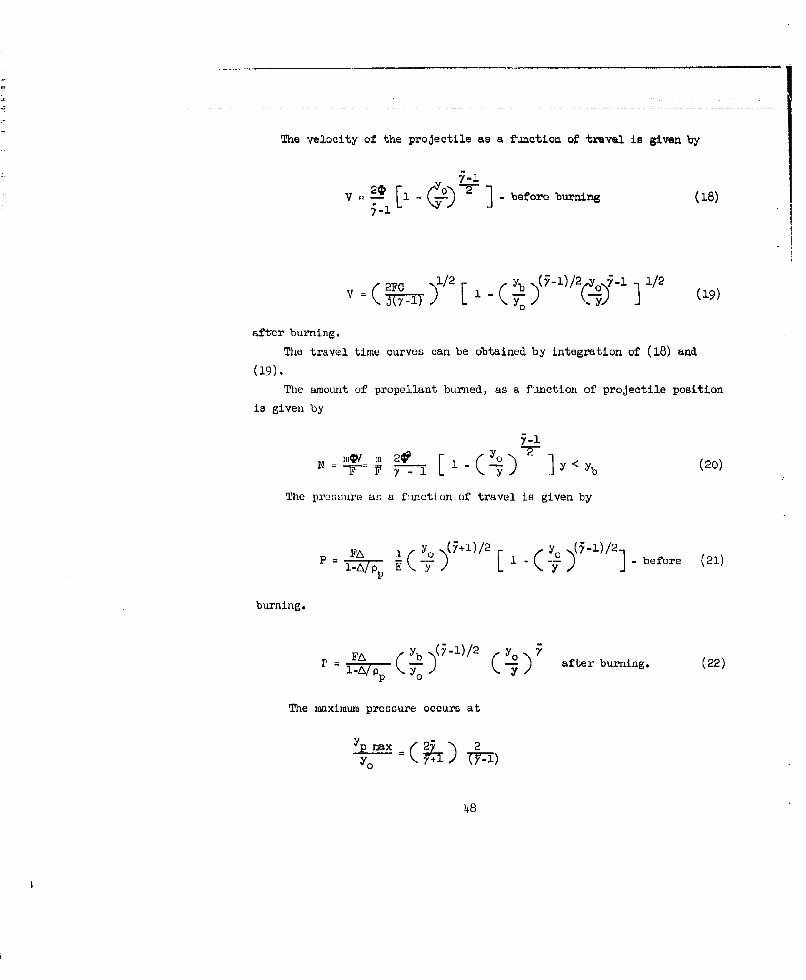
The velocity of the projectile as a function of travel is given by
~~ - ** ] - before buxnig ~(87-'
2FC 1/2 L b 71)/2()V* 1/0 1/2 (19)
after burning.
The travel time curves can be obtained by integration of (18) and
(19).The amount of propellant burned, as a function of projectile position
is given by
N = 2 y- - y [ (Y j] < b (20)
The pressure as a function of travel is given by
y (+ I )/2 yFA [ L_# ] before (21)
burning.
PKA ) after burning. (22)
The maximum pressure occurs at
Yp max (25) 2
48

independent of all other conditions, provided yp max <Yb Otherwise
the maximum pressure occurs when the propellant is all burned. The value
of the maximum pressure is
JA 2 i rl+I I5 23
(+ ) AI-i)
p p I-E, E > -l/2 (24F)miax Pb -1 p L
The temperature TnK of the gas is given by
yT = T (.--2 before burning (25)
vb)(7"i)/2 '*_o) ' -)
T = T0 after burning. (26)0
In order to adapt the system to any particular gun the followingprocedure is followed. For the connection between in and mo, the relation
m .o4 (mo + C/3) is used. (27)
For the effective ratio of the spocific heats, an average value =1.36
is used. The values of in0 V0 , J, A and F are known gun constants.
The value of Q and E are determined from observed maximum pressure accord-
ing to equation (21) or (22). Finally a check on the ballistics is
obtained by comparing the muzzle velocity as calculated from equation (19)
with the observed value.
The absolute size of the gun has been completely eliminated in the
ballistic formulas given by equations (16) through (26). This system
contains only one parameter, namely yb/Yo' or the constant E. If this
quantity is kept constant, the ballistic curves (travel, velocity,
49
temperature, and pressure - time) will be similar no matter what
values are given to the other parameters. Thus by .
1 through 5, a one parameter group of possible travel-tme curves uder
variation of all conditions such as ratio of projectile mass to charge mass,
loading density, web thicknuess, and composition of the propellant are
possible.
As already pointed out, guns of different absolute size will have similar
ballistic curves. Then by rewriting equation (19)
V L 1 1 -( a (28)y dt Z o _71)L /
0 ~ 0 V
and introducing a new reduced time
t 1 _ 2 20 AI r; _ Ce - (5r-1) ('-A/ p) U (90 000
We get
a _ _ . ( -a ) / 2
T' Yo
which states that the velocity-time curves are the same for all guns if
described in the reduced time scale r.
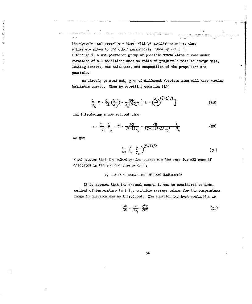
V. REDUCED EQUATIONS OF HEAT CONDUCTION
It is assmed that the thermal constants can be considered as inde-
pendent of temperature that is, suitable average values for the temperature
range in question can be introduced. The equation for heat conduction is
be k e (31)
50

The boudArY eowukdtimn are
h(S -e0 + k 0 (52)
The heajtmtlnsfer coefficient h contains the friction factor X
as a multiplenf censtarit, h = Xho .
If we €Osi2ier a gaa with definite ballistics, then h and e are
universal fuhatkjions of -the reduced time variable
- at; 1 "(33)0 0
In ordert.o make utse of this correspondence, a new system of time
and space vsria-^bea is introduced
- at, and t 1 (34)
where the rlatzino of P to a is given by
k Ps 1 3=ICP / 3.
Then equatims (31), ( 32), and (33) become
a-q I e (35)
1L( 6 9) + o (36)
o (o1. ) (37
Where the red-ie& hea transfer coefficient H is
h Xho (38)(akCOCf!2) ' = (c-kCp /2)"'
51

These equations are now universal except for the multiplying
factor % This factor contains the friction factor, the
thenal constants of the steel, and the time parameter 0 which is determined
by the size or the gun. All combinations that give the same h factor
will give the same temperatures in the system and the results in the
actual xt system can then be obtained by simple conversion of scales.
Now we can collect the complete formula for the heat transfer
coefficient as functions of the reduced travel variable y, which in turn
is a universal function of T. The assumption of equal distribution of
unburned propellant is used.
By use of equations (5), (13), (18), (20), and (33) we find
xHC' ) (Lfr) (39)
XU
where
%,OC 1 /2 1 .)/2
y 2- 1/2
f( ) =([O))
('- ;)[ + V~ {l +~).l2 Q - pE(-/ l-A/p
before burning.
52

f I........after burning, (42)
(a -A/1 4- lAP)
Using equxation (25) and 26) we find that the gas temperature 0gPreferred to an initial temperature of the gun of 3OOPK is given by
y 1/2 (5.-1)9 g + 300 T( -0 before burning, (43)
b 1 2 U - 1 ) Yo Y7-"
ag+ 300= T) =T 1 (44)
after burning.
In H( r) the factor x S/x ° gives the location along the bore for which
the gun temperature is to be determnined. The factor L which is called the
heating parameter depends on the friction factor, thermal conductivity of
the gun steel and ballistic constant of the gun. The absolute size of the
gun is contained only in the factor (C/A)/2 , while the other quantities
-- A, 0, E, have the character of specific quantities. The integration
must start at the value of t corresponding to the selected x (where
ppys = xs " C/Ap p) and must continue usinr, equation (43) and (44) until the
time when the projectile is at the muzzle or to point ym"
VI. THE CHOICE OF THE FRICTION FACTOR X
The friction factor is theoretically calculable only for certain
relatively simple cases of steady state fluid flow over smooQth walls. It
is obvious that these conditions do not hold in guns. However, as a first
approximation, formulas based on analogy to those obtained for steady flow
over smooth walls are used by NSN.
53

NSN used two methods for determination of a value of X. The first
used the equation'
X = (3.46 + 4 log,, ro/r) " 2 (45)
where thickness of the boundary layer B for smooth surfaces is replaced
by a roughness parameter r that measures the size of the irregularities.The exact meaning of r is not well defined, since the friction factorwill depend also on the form and arrangement of the irregularities. NSN
made an attempt to determine a value of X for guns from data on theerosion of nozzles. They were not successful in making a satisfactory
transition.
The other method NON used was to determine values of X from heattransfer data obtained from .50 caliber machine gun firings. A value of
X was computed from heat input data obtained at the origin of rifling.
The values vary widely because of imperfection in the insulation of the
calorimetric ring used. Corrections were made for these variations, butvalues of I still varied from round to round.
Workers at Catholic Universit9 applied the NSN theory to the calcu-
lation of the friction factor for several guns of different calibers.They used heut input data derived from bore surface and embedded barrel
thermocouplec. The reoultv, indicate that X varies over the bore surfacefrom breech to muzzle and varies for different guns of the same caliber.
It is the opinion of the writers that X is a "fudge" factor that mustbe experimentally determined for the gun in question, and at the desiredlocations along the gun baXrel. A discussion of our technique for deter-
mining X from heat input data is contained in the body of this report.
VII . THE CALCULATION OF THE IMAT INPUT. Q
If one has knowledge of the temperature distribution in a gun barrel,he also can determine the total heat input Q to that section of the bore
surface by either one of the following formulas:
54

b( e t (4.6)0
q OPSO(Z-)z • (47)
o
Since eq% itn (47) i the easier of the two to integrate, no further
use of ( wl ()w be ille de.
Equoi 0 o (47) a=be expressed in the form
~Q[ P) O.J6(z)dz = cpG(2k/Cp57)1/2 f" e(t.)6.
0 0
- 2kOp/7I(r,ys/yo) . (48)
The 0 ntegral I (-, ys/yc) should be evaluated at a time when anylater hek. txansfom--ld cn be neglected. When this is done a value of all
of the ht kt -transferz' -ed from the propellant gases to the gun is obtained.
These in mrls sarea -ot sensitive to changes in the length of the gun,
YM/Yo, M. they w b - e evaluated for all guns.
55

1. Goldstein, S. Modern Developments in Fluld Dynamics, OxfordUniversity Press (1938) p. 338
2. Boyd) Marjorie; Dooling, J.S.; Griffins, Virginia and Maller, R.
Heating and Erosion Studies in Guns, A Final Report on Task 3,Contract NOord 10,260, Chemistry Department, The Catholic Universityof America, Washington, D.C. pp. 18-103.
56

.. . .. . .... .
D)ISTRIBUTION LIST
No. of No. ofOrganization Copies Organization
10 Commander Redstone Scientific InformationArmed Services Technical Center
Information Agency ATTN: Chief, Document SectionATTN: TIPCE U. S. Army Missile CommandArlington Hall Station Redstone Arsenal, AlabamaArlington 12, Virginia
1 Commanding GeneralCommanding General U. S. Army Ammunition CommandU. S. Army Materiel Command ATTN: ORDLY-AREL, Engr. LibraryATTN: AMCRD-R-PE-Bal, Joliet, Illinois
Mr. G. E. StetsonResearch and Development 3 Chief, Bureau of Naval Weapons
Directorate ATTN: RMMP-2Washington 25, D. C. RMMP-331
RRE-6Commanding General Department of the NavyU. S. Army Materiel Command Washington 25, D. C.ATTN: AMCRD-DE-W,
Mr. Stanley Swipp 2 Commanding OfficerResearch and Development U. S. Naval Propellant Plant
Directorate ATTN: Technical LibraryWashington 25, D. C. Indianhead, Maryland
Commanding Officer 1 CommanderHarry Diamond Laboratories U. S. Naval Weapons LaboratoryATTN: Technical Information ATTN: Technical Library
Office, Branch 012 Dahlgren, VirginiaWashington 25, D. C.
2 CommanderCommanding General U. S. Naval Ordnance LaboratoryFrankford Arsenal ATTN: LibraryATTN: Propellant and Explosives White Oak
Section, 1331 Silver Spring 19, MarylandPhiladelphia 37, Pennsylvania
2 CommanderCommanding Officer U. S. Naval Ordnance Test StationArmy Research Office (Durham) ATTN: Technical Library BranchBox CM, Duke Station China Lake, CaliforniaDurham, North Carolina
1 Director5 Commanding Officer U. S. Naval Research Laboratory
Picatinny Arsenal ATTN: Mr. Walter AtkinsATTN: Feltman Research and Washington 20, D. C.
Engineering LaboratoryMr. Sidney Kravitz
Dover, New Jersey
57

DISTRXBUTION LIST
No. of No. ofCopies Organization Copies Organization
Director 1 National Aeronautics and SpaceSpecial Projects Off ice AdministrationDepartment of the Navy Langley Research CenterWashington 25, D. C. ATTN: Library
Langley Air Force CenterChief of Naval Operations VirginiaATTN: OpO3EGDepartment of the Navy 1 National Aeronautics and SpaceWashington 25, D. C. Administration
Goddard Space Flight CenterU. S. Naval Ordnance Plant ATTN: LibraryATTN: K. L. Brown, Librarian Greenbelt, Maryland
Engineering DepartmentLouisville, Kentucky I National Aeronautics and Space
AdministrationAPGC (PGAPI) George C. Marshall Space FlightEglin Air Force Base CenterFlorida ATTN: Library
Huntsville, Alabama2 U. S. Department of the Interior
Bureau of Mines 1 National Aeronautics and SpaceATTN: M. M. Dolinar, Administration
Reports Librarian Manned Spacecraft CenterExplosives Research Lab ATTN: Library
4800 Forbes Avenue P.O . Box 1537Pittsburgh 13, Pennsylvania Houston 1, Texas
National Aeronautics and Space 2 Aerojet-General CorporationAdministration ATTN: Librarian
ATTN: Office of Technical P. 0. Box 296Information & Educational Azusa, CaliforniaPrograms, Code ETL
Washington 25, D. C. 1 American Machine and FoundryCompany
2 Scientific and Technical ATTN: Phil RosenbergInformation Facility Mechanics Research Department
ATTN: NASA Representative 75C1 North Natchez AvenueP. 0. Box 5700 Niles 48, IllinoisBethesda, Maryland
1 Arthur D. Little, Inc.National Aeronautics and Space ATTN: W. H. VarleyAdministration 15 Acorn Park
Lewis Research Center Cambridge 40, MassachusettsATTN: Library21000 Brookpark RoadCleveland 35, Ohio
58

DISTRIBUTION LIST
No. of No. of-pies Orgnization C Organization
2 Armour Research Foundatio'. of I Jet Propulsion LaboratoryIllinois Institute of Technology ATTN: I. E. Nwlan
Technology Center Chief, Reports GroupATMN: Fluid Dynamics & Propulsion 4800 Oak Grove Drive
Research, Department D Pasadena 3, CaliforniaChicago 16, Illinois
1 Minneapolis-Honeywell Regulator2 Atlantic Research Corporation Company
Shirley Highway & Edsall Road ATTN: Mr. Robert GartnerAlexandria, Virginia Ordnance Division
Hopkins, Minnesota
The Franklin InstituteATTN: Miss Marion H. Johnson, I Midwest Research Institute
Librarian ATTN: LibrarianTechnical Reports Library 425 Volker Boulevard
20th and Parkway Kansas City 10, MissouriPhiladelphia 3, Pennsylvania
3 Solid Propellant Information
Hercules Powder Company AgencyATTN: Technical Information Applied Physics Laboratory
Division The Johns Hopkins UniversityResearch Center, Silver Spring, Maryland
Dr. Herman Skoinik910 Market Street 10 The Scientific InformationWilmington 99, Delaware Officer
Defence Research StaffHercules Povder Company British EmbassyAllegheny Ballistics Laboratory 3100 Massachusetts Avenue, N. W.ATTN: Library Washington 8, D. C.P. 0. Box 210Cumberland, Maryland 4 Defence Research Member
Canadian Joint Staff2450 Massachusetts Avenue, N. W.Washington 8, D. C.
59

12 I ~~i'i 12I bib ii U'Ii
~.1I
1a ii ~I0
d
~~ ~4~fi3~
I~ 44.'
~ 1-~
0iiF" ~i Jill
~U h2 -~ ~~ ~