unclassified *iiiiiiiiiiiiilfflf wright-patterson afb oh ... · 1 3 2 11111 ~o~116 1.8 1111il25...
TRANSCRIPT

fib-A172 528 AN ANALYSIS OF PILOT TRAINING FOR F-16 IMPLEMENTATION /BY THE REPUBLIC OF (U) AIR FORCE INST OF TECHWRIGHT-PATTERSON AFB OH SCHOOL OF ENGI. Y J LEE
UNCLASSIFIED NOV 85 AFIT/GOR/OS/85D-t2 F/G 5/9 UL*IIIIIIIIIIIIIlfflfEllllllllllllEEIIIIIIIIIIIIEE/I//////I///EEEIIIIEIIIIIIIEEIIIIIIIIIIIIEllllllll~lllE

1 3 2
11111 ~o~116
1.8
1111IL25
MICROCOPY RESOLUTION TEST CHART
NAIONAL BUREAU OF STANDARDS- I963-A
%I~ %I~
v''~L.

AFIT/GOR/OS/85D-12
00
Lfl
'O
N
IN
AN ANALYSIS OF PILOT TRAINING
FOR F-16 IMPLEMENTAIONBY THE REPUBLIC OF KOREA AIR FORCE
THESIS
YOUNG JONG, LEE
AFIT/GOR/OS/8 5D-I 2
DTIC01- EL{.ECTE
N OCT 0 , 1986
E
_Approved for public release; distribution unlimited
ditibto uniie

AFIT/GOR/OS/85D-12
AN ANALYSIS OF PILOT TRAINING
FOR F-16 IMPLEMENTATION
BY THE REPUBLIC OF KOREA AIR FORCE
THESIS
Presented to the Faculty of the School of Engineering
of the Air Force Institute of Technology
Air University
In Partial Fulfillment of the
Requirements for the Degree of
Master of Science in Operations Research
4ulIL" Ac c I For
FT
Yong Jong, Lee J " ' I-I . . . . .
Major, ROKAF
-November 1985
Approved for public release; distribution unlimited
, . ] , ,:. .' ,, F : < " '-; % Z " *% **,* * . ,. -...- .. ' / % ' - .

Preface
This study was intended to provide insight into the
pilot training for the F-16 implementation by the Republic
of Korea Air Force (ROKAF) and to identify significant
factors affecting the training process.
A simulation model of the F-16 pilot training system was
developed using a SLAM network with FORTRAN subroutines.
This model transforms student pilots and upgrading
instructor pilots into F-16 pilots and instructors using
limited resources such as instructors, number and type of
aircraft, and airwork areas based on requirements of the
training syllabus.
In the development of this study, I am deeply indebted
to my faculty advisors, Major William F. Rowell and
Lieutenant Colonel Palmer W. Smith, for their special
guidance and advice. Also I sincerely appreciate Lieutenant
Colonel Sung Ul, Kim, a ROKLF representative for the Peace
Bridge Program, in ASD/YPXI USAF. Without his cooperation
and assistance, this analysis would not nave been possible.
Finally, I would like to thank my wife, Yong Hee, for her
loving support, patience, and encouragement through this
study.
Young Jong, Lee

Table of Contents
* Page
Preface................................................ i
List of Figures.............................. ............ vi
List of Tables.............................. ............ vii
Abstract................................................ viii
I. Introduction.......................................... 1
Background....................................... 1Problem Statement............................... 2Research Questions ........... *objectives.................................... ... 4Scope............................................ 4Measure of effectiveness........................ 5Study Approach.................................. 5
Understanding the Training Program .... 6Understanding Training System Structure. 7Model..................................... 7Verification and Validation................ 8Identifying Significant Factors............ 8
Summary......................................... 9
II. Literature Review.................................... 10
Introduction................................ 10Peace Bridge Program Management Documents. 10
Peace Bridge Program Management Plan . 10Program Management Review.................. 11F-16 Implementation Plan................... 12
Training Syllabi................................ 14Related Studies................................ 15Summary......................................... 18
III. Model Formulation................................... 20
introduction.................................... 20System Descr iption.............................. 20
Proposed F-16 Squadron Structure ........... 20Training Process........................... 21Components and Variables................... 25
Model Development............................... 27Data Collection............................ 27Flight Training Mission Types.............. 34Model Assumptions.......................... 37Model Building.............................. 38
Transition Training Module............. 39
4."d

. . . .. . .. .- P . , - . . .
Upgrading Instructor Pilot(UIP) Training Module .................. 44Other Modules ........................... 45
Verification ................................ 47Validation .................................. 48Summary .................................... 50
V IV. Experimental Design ................................. 52
Introduction ................................ 52Selection of Factors ............................ 52Choice of Factor Levels ........................ 55Selection of Response Variables ............... 56The Designs ................................. 56Run Length and Number of Replications ....... 57
Summary .................................... 60
V. Analysis of Experimental Results .................... 62
Introduction ................................ 62Analysis .................................... 62
Main Effects for Average Days toComplete Total Training .................... 62Interaction Effects for AverageDays to Complete Total Training ........... 68
Main Effects for Average Days toComplete Transition Training .............. 69Interaction Effects for Average Daysto Complete Transition Training ........... 73Main Effects for Average Days toComplete UIP Training ...................... 74Interaction Effects for AverageDays to Complete UIP Training ............. 75
Sensitivity Analyses ............................ 78Sensitivity to Transition StudentPilots .................................. 78Sensitivity to F-16Ds ...................... 79Sensitivity to Aircraft Failure Rates... 79Sensitivity to MissionEffectiveness Rate .......................... 80
Summary .................................... 80
VI. Conclusions and Recommendations ..................... 82
Conclusions ................................. 82Recommendations for Further Study ............. 85
Bibliography ......................................... 86
Appendix A: Data for Design of Experiment ............. 88
iv
a'----z
Appendix B: Data for Sensitivity Analysis.............. 89
Appendix C: Statistical Results for ANOVA............ 9
Appendix D: Statistical Results for MANOVA............. 94
Appendix E: Statistical Results for Sensitivity
Analysis................................... 106
Appendix F: F-16 Pilot Training model (SLAM Code). 110
Appendix G: F-16 Pilot Training Model
(FORTRAN code)............................. 140
Appendix H: Statistical Analysis Program (BMDP) ... 144
Vita..................................................... 145
'- .~v

List ofFiue
Figure Page
1. Spring Weather Cancellation Rate................... 30
2. Summer Weather Cancellation Rate................... 30
3. Autumn Weather Cancellation Rate................... 31
4. Winter Weather Ca ncellation Rate................... 31
5. Phase Logic Flowchart............................... 40
6. Typical Mission Type Flowchart..................... 41
7. Main Effects on Average Days to Complete
Total Training...................................... 65
8. Interaction Effects on Average Days to
Complete Total Training............................ 66
9. Main Effects on Average Days to Complete
Transition Training................................. 71
10. Interaction Effects on Average Days to
Complete Transition Training....................... 72
11. main Effects on Average Days to Complete
UIP Training........................................ 76
12. Intraction Effects on Average Days to
Complete U.IP Training............................... 77
vi

List of Tables
Table Page
I. Transition Training Mission Type................. 35
ii. uiP Training Mission Type........................ 36
III. Model Variables................................... 53
IV. Factor Levels..................................... 56
V. Design Matrix..................................... 58
VI. Effects on Average Days to Complete
Total Training.................................... 64
VII. Effects on Average Days to Complete
Transition Training............................. 7
VIII. Effects on Average Days to Complete
LJIP Training...................................... 75
vii

AFIT/GOR/OS/S 5D-l 2
Abstract
Insight for the pilot training for the F-16
implementation for the Republic of Korea Air Force is
provided, and statistically significant factors affecting
the trdining process are identified. To analyze the F-16
pilot training system of the transition period, a simulation
model of the training system is built using a SLAM network
with FORTRAN subroutines. Four factors of interest to the
planners are investigated from a baseline to an expected
value with respect to the average days to complete total
training and the average days to complete transition and
upgrading instructor pilot training used as measures of
effectiveness. Several factors and interactions are
significant for each response variable. The most
significant finding is that increasing the number of student
pilots per class from six to seven reduces the number of
classes required from eight to seven, saving about three
months. This increased student load can be accomplished
within allocated resources.
Any change to the F-16 implementation plan can be
analyzed prudently with this model. This model is flexible
to different scenarios and prodution goals by changing input
variables. The model can be used as a general one for
Vill

analyzing a transition period of any F-16 implementation,
using limited resources on a predetermined syllabus schedule
* with random variables.
a,
4'.
~ --
p*i
V
4..
a. ~*
4. ,-..d.
'.4. 4.-a ix
4.
'4.
-4
!'*4%
*~-p*~*J - .~* 4W.a4.*~(%a.... '~. ' . ~- - a- * U ' .. '~. a.- *~~*a ~ 444~ ~
An Analysis of Pilot Training
for F-16 Implementation
by the Republic of Korea Air Force
I. Introduction
Background
The Republic of Korea (R.O.K.) decided to strengthen
its air power and modernize its Air Force to deter a North
Korean invasion. Many studies have been done to determine
the type and number of aircraft needed for deterrence. The
studies conclude that the F-16 would be the most suitable
__ one for the Korean situation. The F-16 will hence take the
most important role in the R.O.K. Air Force (ROKAF)
Modernization Program; it will be a critical component for
peace in the Korean peninsula.
The Peace Bridge Program (PBP) for the procurement of
the F-16 btarted 1 December 1981 with the signature of the
Letter of Acceptance (LOA). Under this agreement, the F-16
aircraft will begin production deliveries in February 1986
and continue until January 1989. The first in-country
delivery will be in April 1986 and continue until February
1989.
Many people concerned with this program have developed
a Program Management Plan (PMP) which covers all aspects of
1
• * w- ~ - -
the Peace Bridge Program from the LOA to operational
readiness. The PMP is the basic instruction which ties all
actions together to ensure an efficient process of sale and
transition to the ROKAF. These actions include contractor
support, training of all personnel in 17 specialties,
logistics support, initial spares, base preparation, and
related areas.
The adoption of a mility fighter aircraft into a
country's Air Force requires many actions to be done.
Implementation can be divided into a procurement phase, an
initial transition phase, and a fully operational phase.
The actions for procuring the F-16 have been completed
already and production of the first aircraft has already
begun. From an operational aspect, the initial
transitioning phase is much more important and requires
systematic and formal detailed analysis.
Problem Statement
The ROKAF desires the F-16 fighter squadron to be
operationally ready for all missions by the required date.
It is concerned about problems which may affect the
implementation and time to operational readiness and how
these problems can be overcome or minimized for an effective
and efficient transition.
A key element in the total program is the training of
ROKAF pilots to fly the F-16. Many factors may affect the
timely training of pilots. These include:
2

1. workload in the training wing,
2. monthly weather cancellation rate,
3. aircraft available for training,
4. F-16 delivery rate to Korea,
5. student pilot attrition,
6. syllabus of instruction,
7. number of instructor pilots,
8. number of hours of academic training,
9. students per class,
10. number of sorties required for qualifying,
11. student-to-aircraft ratio,
12. daylight hours per month,
13. days to transition new instructor pilots,
14. number of sorties to transition an instructor
pilot,
15. number of pilots required for operational
readiness,
16. starting date of training,
17. training effectiveness.
Research Questions
How will these various training factors affect the
ability of the ROKAF to produce combat ready F-16 pilots to
meet the desired date for full operational readiness? What
actions are most likely to increase the probability of
meeting the desired operationa~l capability date?
3

Objectives
This research focuses only on the pilot training
aspects of the PBP and the F-16 implementation plan for the
ROKAF. The overall objective of this research is to:
1. identify those factors which significantly affect
the time required to produce the number of F-16 pilots for
full operational readiness in Korea,
2. identify those factors which significantly affect
the average number of days to graduate a class.
The accomplishment of these objectives will provide
valuable information to key ROKAF decision makers to help
minimize or avert problems in the pilot training portion of
the PBP and help to ensure the highest possible probability
for successfully providing the required F-16 pilots.
Scope
The F-16 implementation plan for the ROKAF and the PBP
provide general guide lines for operational plans,
logistics, personnel, and so on. This research will focus
on the pilot training of the operational aspects of the
plan. The ROKAF HQ DCS/O will analyze the portion of the
operations to implement the F-16 successfully.
Furthermore, The effort of this research centers on the
initial transition phase, which can be defined as the time
period between the first and the last aircraft delivery.
4

4 This study will focus on the time frame of the first F-l6
pilot training in Korea until the last class during the
transition.
Measures of Effectiveness
The measures of effectiveness for this study will be
the average number of days to generate the number of pilots
required for operational readiness for each F-16 squadron
and the average number of days to graduate a class. These
measures will show how the factors given in the problem
statement affect the transition. And these will vary
depending upon the change of the input variables. Those
factors significantly affecting these measures of
effectiveness will be identified for further consideration.
Study Approach
The overall study approach for accomplishing the
objectives of this study is to:
1. Understand the pilot training program plan
associated with the F-16 implementation by the ROKAF.
2. Analyze the structure of the pilot training system.
3. Construct a flow diagram of the pilot training
program plan and identify key factors, potential bottlenecks
and problem areas.
4. Determine required data and assumptions.
5. Collect data and develop probability- distributions.
5

6. Build a simulation model which will represent the
structure of the pilot training system.
7. Verify and validate the model by insuring that the
computer code performs as desired.
8. Analyze the experimental design for the factor
evaluation and identify those factors which significantly
affect the training of the F-16 pilots.
9. Simulate alternative approaches to overcoming
problems discovered.
Understanding the Training Program. The F-16
implementation plan for the ROKAF gives the overall program
guidance, including the first portion of flight transition
training. A more comprehensive F-16 pilot training plan has
been studied in the ROKAF Headquarters (HQ) Deputy Chief of
Staff for Operations (DCS/O). However, this plan does not
contain the details required to model the F-16 pilot
training.
The above information can be supplemented by
incorporating the judgement of planners at HQ ROKAF and at
USAF Aeronautical Systems Division (ASD/ YPXI) and at USAFN.
*International Logistic Command (ILC). Assumptions on the
key issues will be based upon knowledge and experience of
personnel in the Peace Bridge Program.
6
N~~~~2 N ' L Le -- .

Understanding Training System Structure. The pilot
training program, the existing USAF F-16 pilot training
system, and the judgement of planners (HQ ROKAF,
USAF/ASD/YPXI, and USAF/ILC) will assist in defining the
structure of the F-16 pilot training plan and the
relationships among the system variables. Factors which are
initially identified as affecting timely training of pilots
will form the basis for identifying necessary data to be
gathered. The following data was gathered from the HQ
ROKAF DCS/O and the USAF/ASD/ YPXI or USAF/ILC: workload in
the training wing, monthly weather cancellation rate,
daylight hours per month, aircraft available for training,
aircraft abort rate and attrition rate, F-16 delivery rate
to ROKAF, number of sorties for transition of pilot and
upgrading instructor pilot (UIP), number of student pilots
(SP) and IPs per class, number of hours of academic
training, student to aircraft ratio, number of pilots
required for operational readiness, and starting date of
training.
Model. The structure of the training system is
translated into a SLAM simulation model and analyzed using
experimental design. Simulation appears to be an
appropriate tool because the F-16 pilot training is a
lengthy, complex process involving a large number of random
events. The result of simulation provides the information
;-..'.
O,7
about what may happen, which variables are most important,
and how variables interact.
Verification and Validation. The pilot training model
must represent the system well enough to accurately answer
the basic questions described above. The model is
constructed especially for the ROKAF F-16 situation and
verified fully. But this new F-16 implementation by the
ROKAF lacks complete historical data. Because of the lack
of ROKAF historical data, validation is difficult, but is
attempted. Values assumed for the variables lacking
historical data are used for checking the model for
reasonable output and for sensitivity analysis.
Identifying Significant Factors. Within the relevant
range of the variables of interest, high and low values are
used for inputs for identifying the significant factors
affecting the training of the F-16. The necessary
combinations of variables and the number of replications are
determined using experimental design.
Analysis of variance (ANOVA) is used to identify the
significant factors. Sensitivity analysis is performed for
the input variables and input distributions.
8

- Summary
The implementation of the F-16 by the ROKAF, which will
be a most important part in deterring a North Korea
invasion, requires many things to be done. The ROKAF
desires the F-16 squadron to be operationally ready for all
missions as soon as possible during the initial transition
phase.
This study is intended to identify how various factors
affect the F-16 pilot training. The measures of
effectiveness of the training system model are the days
needed to produce the required number of F-16 pilots and the
* average days to graduate a class. Simulation is used as a
tool to produce these measures of effectiveness.
The overall steps taken in this study are: 1.
understanding the training system, 2. analyzing the
structure of the training system, 3. modeling, 4.
verifying and validating the model, and 5. identifying
significant factors.
A)9

II. Literature Review
Introduction
Several sources of information are needed to develop
the F-16 pilot training model for Korea. Before discussing
the techniques, it is important to review the plans and key
sources for the F-16 implementation by the ROKAF and the
methods used in past studies of similar pilot training.
The basic requirements for F-16 pilot training phase
can be found in Peace Bridge Program Management documents.
These related training plans are reviewed first, followed by
the F-16 Implementation Plan. The syllabus of instruction
for the F-16 pilot training is key to this study and is
discussed in detail. The PBPMP, related training plans, and
the syllabus of training are all the key sources for this
study. Finally, studies which have looked at USAF pilot
training are investigated for methodology and approaches.
Peace Bridge Program Management Documents
Peace Bridge Program Management Plan (PBPMP) (8). The
PBPMP provides guidelines for the implementation of the F-16
acquisition program for the ROKAF. The PBPMP contains
requirements, responsibili-ties, program management
milestones, logistic support, maintenance, training,
aircraft delivery, and operational concept which are needed
to successfully complete the ROKAF F-16 program. It
10

provides the primary guidance for pilot training for F-16
implementation by the ROKAF. The program summary outlines
an initial overview of general description and concept for
the ROKAF F-16 program. The summary states that initial
pilot training will be conducted in the CONUS and in the
ROK. The major tasks of ROKAF representatives are described
in the organization and responsibility section. The
starting date of flight training in CONUS and the aircraft
delivery are found in the program management schedule with
other event's milestones.
The PBPMP outlines the recommended minimum training
program for the ROKAF personnel for pilot training and
technical training. For pilot and maintenance training, the
ROKAF personnel will be trained through a cadre approach.
The objective of pilot training is defined as providing
F-16C/D flight qualification and intructor training for
eight ROKAF pilots. The CONUS training of the two ROKAF
pilots will be completed by March 1986. The top-off training
will be taken in the ROK. The PBPMP also contains schedules
about courses and typical course contents. (8:11-1; 11-31)
Program Management Review (PMR) (9). The minutes of
PMRs formally document management review, logistics,
training, action item status, and discussions. The latest
review is the fourth Peace Bridge PMR convened October, 1984
at HQ/ ROKAF, Seoul, Korea. As a directive outline, it
provides informations on changes to the basic PBPMP.
' "11

The training status briefed at that meeting shows more
information of technical training and pilot training status.
A proposed tentative course outline of the F-16 transition
course and Instructor Pilot (IP) course is documented in the
training section. The transition training course takes 22
sorties, 28.2 flying hours, and 225 academic hours. The
upgrading instructor pilot course is completed with 16
sorties and 38 academic hours.
The initial technical training of the ROKAF aircraft
technicians consists of USAF technical training and
contractor technical training with completion by March 1986.
After returning to Korea, these technicians will support the
F-16 aircraft operation and develop further in-country
technical training for additional ROKAF personnel. Special
efforts are being made to ensure the aircraft can be
supported fully at the initiation of training in Korea.
(9:33-34; 199-230)
F-16 Implementation Plan (12). The integrated effort
P of the ROKAF HQ, ensuring the successful F-16 implementation
into ROKAF is contained in the F-16 Implementation Plan.
This outlines all aspects of transition, including an
orderly conversion and a tentative sequence of events. The
plan contains objectives, assumptions, concept of operations
for operations, plans, logistics support, personnel,
intelligence area, and inspector general responsibilities.
ROKAF HQ DCS/O is responsible for the plan.
12

Only the operational aspects of the plan are within the
scope of this research. The plan states that the first
transition class of F-16 student pilots will enter t.,,e
* course in August 1986. Thereafter, each class w4 L start
the transition training every three months until all the
pilots required for operational readiness are trained.
There will be certain criteria for selecting the
student pilots such as total flying hours and the level of
experience. After the first class finishes the transition
training, some of them will be selected and upgraded to
instructor pilots. There will be no upgrading instructor
pilots from the first class. From the second class on, two
pilots are selected from the previous transition class for
upgrading to instructor pilots. Upgrading instructor pilot
training will start at the same time as transition training,
except for the first and the last transition class.
During the training period, pilots who finish the
transition training, but are not selected for upgrade
instructor pilot training, will share the available aircraft
with student pilots in orler to meet minimum reguirments and
increase proficiency. Therefore, the student pilots and the
instructor upgrade training will compete for the same
aircraft resources.
* .9.,..13

I___ C) T I a I n I(nl)
liLArIne RDKAF H-1 nas not developed a detail syllabi for a
trans--tion training course and a instructor pilot upgrade
course. The first two pilots trained in CONUS will be
responsible for developing several syllabi in detail after
they return to Korea. In this research, the USAF training
syllabi is used for determining the required days of
transition and upgrading because it probably will be used as
the base transition syllabi for the ROKAF syllabi.
U, The USAF transition training course syllabus provide
overall training guidance and prescribes the amount of
instruction normally required for transition training of
student pilots. It contains information about course
accounting, course management, academic training, aircrew
.~' training devices, and flying training.
The course entry prerequisites, the status upon
completion, the course inventory, and the aircraft
configuration are described in the course accounting
section. The graduates are qualified to fly F-16C/D
aircraft. Selected graduates will enter instructor pilot
upgrade course.
The course management section explains the training
standards, the grading criteria, the general instructions,
the course map, and the management flow chart. The course
map indicates that before a certain type of instruction
starts, a student pilot must have successfully completed all
prerequisites, both flying sorties and academics.
41

'1.
The academic training section describes the detailed
information of each lecture, seminar, and tests. The
aircrew training devices are an egress procedure trainer, a
cockpit familiarization trainer, a static aircraft, and an
advanced simulator. Other trainers can be substituteo for
static aircraft.
The flying training section is divided into three
phases: Conversion, Air-to-Air, and Air-to-Surface. The
special instructions, mission descriptions, and mission
objectives are covered for each phase and for each mission.
Missions requiring an F-16C may be replaced with those
requiring an F-16D, if the mission is flown effectively and
no F-16C's are available at all. During the course a
student may fly as much as four additional sorties if
mission standards are not attained. For optional flying
experience, a student may observe the instructor missions by
riding in the rear cockpit. The detail mission descriptions
are provided in the flying training section.
The structure of the syllabus of the instructor pilot
upgrade training course describes the overall training
guidance required for upgrading instructor pilot. The
graduates will be prepared to instruct all F-16 formal
courses.
6Zd 15
% ,
-'-

Related Studies
The following studies have similar characteristics in
terms of methodology, system structure, and input variables
to this research.
One of these studies was conducted by Captain John P.
Wood as a graduate student at the Air Force Institute of
Technology(AFIT). He built a model that determines a
scheduled sortie rate in order to obtain a predetermined
training level for one F-4E squadron. By analyzing squadron
structure, scheduled flight operations, scheduled pilot
operations, and time distributiions of each flight
operation, a structural model was first developed. An F-4E
squadron's operations were modeled with a Q-GERT network
simulation program. Finally, an interactive computer model
. ''-. capable of determining a minimum scheduled sortie rate was
developed to allow a predetermined Graduated Combat
Capability level to be achieved. The experimental design
included the structural, functional, and experimental modes.
But his research was limited only to determining
revised sortie rates. This study did not treat the aircraft
and pilots as resources. For the case of tracking aircraft
as resources, daily operations would be highly dependent
upon such random variates as ground aborts, ground delays,
and maintenance turnaround time. (14)
The other related studies have been done on the USAF
undergraduate pilot training program. The first one is a
16
-a f -. z .- ' z - 0 . -. -. - -. 4 - - . . . - - . . . . . ..
thesis written by Major Seth V. Jensen which analyzed the
pilot conversion process for the USAF T-46 aircraft. The
study used the average values for all data taken from the
T-46 Master Implementation Plan. By using hand calculations
his ability to conduct an entire analysis was limited. His
use of average values made it impossible to handle the
N random nature of factors and sensitivity analysis. (5)
An AFIT master's thesis by Major Jack R. Dickinson and
Captain Glenn E. Moses analyzed the conversion from the T-37
A. to the T-46 aircraft in undergraduate pilot training in
order to provide insight into factors which significantly
>1 affect pilot production. Simulation models for T-37 and
T-46 aircraft training were developed in that study. They
structured the undergraduate training system, T-37 squadron
~. ~:<training process, scheduling process, conversion process,
variables, and so on. Finally, they performed an
experimental design.
A model of the undergraduate pilot training system
during the conversion from the T-37 to the T-46 was built
using SLAM networks. The model can be used for pilot
training with limited resources (instructors, aircraft,
* area) on a predetermined syllabus, including random
variables (weather and maintenance abort).
But, undergraduate pilot training involves a single
type of aircraft and relatively constant flying time, the
study did not consider the different types of missions as
17
would be the case in F-l6 pilot training. For example, all
the missions are not performed with a single airplane. In
other words, some missions are conducted with a two-ship
formation, which requires two student pilots and two
instructor pilots. Thus, their program does not address the
F-16 pilot training situation. (2)
The last research effort is an analysis of the
specialized undergraduate pilot training (SUPT) program
performed by Captain Joseph B. Niemeyer and Captain Michael
D. Selva. A simulation model of the SUJPT program was
developed to determine the ability of the current program
design. The research treated the student pilot attrition,
weather aborts, and maintenance abort rates as random
variates drawn from probability distributions. A conceptual
4~ 44r model and mathematical model were translated into a SLAM
network model with FORTRAN subroutines. After that, an
- experimental design was employed and the results analyzed.
The SUPT program design involves the operation of
several phases and several bases. By overlooking the random
nature of such factors as aircraft turn-around time,
* aircraft repair time, and the actual flying time, the
scheduling process is not same as real-world. (7)
Summary
The PBPMP and PMR provide the basic concepts for the
total ROKAF upgrade pilot training program. The combined
18

( efforts of the ROKAF and the USAF are presented in the F-l6
Implementation Plan to ensure an effective and successful
transition. Since the ROKAF has had no experience in
managing the F-16 aircraft, it does not have its own syllabi
of instruction as yet. For this reason, the USAF transition
training syllabus and upgrading instructor pilot training
syllabus were reviewed. The ROKAF has not conducted a
formal detailed analysis of the pilot training for the F-16
implementation, because no proper models exist there. A
variety of similar efforts, analyzing pilot training in
undergraduate pilot training program and an F-4E squadron,
appear in theses studied at AFIT. These studies do provide
ideas for important features and approaches for this study.
However, ignoring the aircraft dependency upon such random
variates as ground aborts, ground delays, and not
considering the type of mission such as the number and type
of aircraft in a mission ,and variable flying time limit
somewhat their usefulness for studying changes in system.
I 19

-- - - - - - - - - - -- - --- -- - - -
III. Model Formulation
Introduction
This chapter discusses the F-16 training environment,
including the general structure to be translated into a
4' -model. Understanding of the system operation should
precede the model construction, since a model is a
description of a system. The squadron structure, the
training process, and the components and variables are first
discussed, followed by a complete description of the model.
System Description
Proposed F-16 Squadron Structure. Before the first
transition class of F-16 student pilots begins, an F-16
% fighter squadron is created. There is no special training
squadron. The transition training is conducted in the F-16
* fighter squadron itself. Information on the squadron
operations and the framework for the system was obtained
from ROKAF, TAC/USAF, and the personal experiences of the
author.
* The basic structure and operation of the F-16 squadron
for this research is the same as any other fighter squadron
* which already exists in the ROKAF. The squadron starts the
transition training with four instructor pilots, two of
which are the UJSAF Mobile Training Teams and six F-16D
20
'VI

aircraft. Eacn class has six transition student pilots,
starts every three months and continues until eight classes
are completed. The UIP training begins with the second
class of transition training, and a total of six classes are
trained. Once transition training is completed, the
graduates continue flying in order to maintain their skills
and to gain more experience as fighter pilots.
The aircraft are delivered every four months. Of the
aircraft delivered some are reserved for transition
training, and the others are used for pilot training.
Hence, as the training progresses and more aircraft are
• .delivered, four F-16Ds and four F-16Cs are reserved for
transition and upgrading IP training. When the first
4: training class starts, only six F-16Ds are available. After
first F-16Cs' delivery, four F-16Ds and two F-16Cs are used.
There will be four F-16Ds and four F-16Cs after second
delivery. Once the UIP training is finished, the last
transition class will use four F-16Ds and two F-16Cs.
Three airwork areas are allocated for the F-16 pilot
training. Only one flight can fly its mission in each area
* at a time.
Training Process. The general structure of transition
training is based upon the USAF transition training
syllabus, the PBPMP, and the PMR.
21
* -

The transition training course academics module summary
is as follows (9:220):
Conversion 105 hours
Air to Air 60 hours
Air to Ground 60 hours
Total 225 hours
The transition training flying module is (9:213-217):
Transition 5 sorties 7.0 hours
Intercept 2 sorties 3.0 hours
Basic FighterManeuver(BFM) 6 sorties 6.6 hours
Dissimilar/Air CombatManeuver(D/ACM) 2 sorties 2.0 hours
Surface Attack(SA) 5 sorties 7.0 hours
Surface AttackTactics(SAT) 2 sorties 2.6 hours
Total 22 sorties 28.2 hours
The upgrading instructor pilot training academics
module is (9:225):
Instructional Technique 12.5 hours
Conversion 8.0 hours
Air to Air 10.0 hours
Air to Ground 7.5 hours
Total 38.0 hours
.4.,
22
aa,. Z

The upgrading instructor pilot training flying module
is (9:221-224):t
Transition 2 sorties 2.8 hours
Intercept 1 sorties 1.5 hours
BFM 3 sorties 3.0 hours
D/ACM 3 sorties 3.0 hours
SA 4 sorties 5.6 hours
SAT 3 sorties 4.2 hours
Total 16 sorties 20.1 hours
There are prerequisites for each flying sortie in the
syllabus. The flying training must follow the proper order
of training exactly, and all academic training prerequisites
should be completed before a certain module starts.
) Nineteen days of ground training precede the start of
flying training for the transition course and five days of
preflight academic training for the UIP course. In
addition, each student takes ninety hours of academic
training for the transition course and twenty-two hours for
the UIP course during each period. After flying training
starts, academic training is given for all the students of
each class rather than student by student. The maximum
amount of academic training per day is eight hours.
Many factors are involved in the scheduling of flight
operations. All sorties are schedi-led based on weather
* conditions, daylight hours, airwork areas, available
23
aicat and estimated turn-around time. A student pilot
is scheduled to fly during the daylight hours of each duty
day.
All sorties are generally scheduled according to the
syllabus of instruction. But if a certain type of aircraft
is not available, the required aircraft may be replaced with
the other type. If a mission consists of two students and
only one has not completed the mission, it is replaced with
another type mission. For example, there are no F-l6Cs
available at all during the first training class. In this
case, all missions requiring F-l6Cs are replaced with the
ones using F-l6Ds.
A typical training mission is described below. Two
hours prior to a flight, the student pilot and the
instructor pilot conduct a one and half hour mission
V briefing. After the briefing they report to their aircraft
for preflight checks and start the engine thirty minutes
before takeoff. After starting the engine and making ground
checks, the flight taxies out to the quick check area where
4 the maintenance crews perform a final inspection. Finally,
they fly the mission. The maintenance debriefing is
conducted with the ground crew after the flight to document
the mission flown and any discrepancies discovered during
the operation. The mission is completed with the one-hour
Pilots' debriefing.
24
a 2 .. 2
Components and Variables. A review of the squadron
structure and the training process identified various
components and variables which should be included in a model
of the F-16 training system. The system consists of student
pilots, instructor pilots, aircraft, training wing workload,
and maintenance support. The student pilots are the key
elements, and all other components are treated as resources.
The daily training process is involved in all of the
components described above, and a sortie is generated and
completed with these resources. Every component is very
important and should be considered to accurately model the
* F-16 training system.
All the variables in the system come from these
components, and those variables which ought to be included
in the model are consolidated to some extent with proper
judgement and experience. For example, the maintenance
complex contains the maintenance crew, logistic support,
ground support equipment, and so on. But if all %these
variables are included in a model, the model would become
too big to be manageable. Aggregating or consolidating
variables makes the model manageable. Later the aggregated
variables may be separated after further understanding the
system and the operating structure. With this approach,
input variables that are explicitly modeled include:
Student Pilots per Class
Upgrading instructor Pilots per Class
4 25

Instructors per Class
Flying Sorties Required for Transition Course
Flying Sorties Required for Upgrading Instructor Pilots
Academic Training Hours for Transition Course
Academic Training Hours for Upgrading instructor Pilots
Number and Type of Aircraft Reserved for Training
Airwork Areas Allocated to Training
Starting Month for Training
Other variables are also involved in the training
structure. The scheduling process is dependent upon the
weather cancellation rate, daylight hours, aircraft failure
rate, repair time, mission effectiveness rate, and flying
time. These are modeled as random variables.
A random variable has a probability distribution
associated with it. A probability distribution is a rule
which assigns a probability to each possible value of a
random variable. (10: 19) Assigning probabilities requires
identifying the underlying probability distribution of a
random variable and defining the parameters of that
distribution. This process is discussed later in more
detail. The following were treated as random variables in
the model:
Weather Cancellation Rate
DaylightHor
Aircraft Failure Rate for Preflight Check
26

"~ Aircraft Failure Rate for Postflight Check
Ground Abort Rate
Aircraft Repair Time
Mission Effectiveness Rate
Flying Time
Model Development
Data Collection. The major sources of data are
ROKAF/HQ, USAF/ASD, USAF/ILC, and USAF/TAC. As previously
mentioned, the ROKAF has no experience operating F-16
aircraft and no historical data. Most of the available data
are based upon USAF experience.
The weather cancellation rate, daylight hours, and
airwork areas allocated for training are the data gathered
from the ROKAF/HQ. The interviews with USAF/ASD/YPXI and
USAF/ILC personnel provided insight into the operation of
the training system. Information on the number of student
pilots, the number of instructor pilots assigned, the number
of aircraft allocated for training, and the general
structure of the F-16 pilot training were obtained from
these interviews. The training syllabi of the transition
training course and upgrading instructor pilot course and
maintenance support data came from the USAF/Tactical Air
Command. After gathering the data, probability
distributions must be developed.
27

The general approach to formulating a tneoretical
distribution is stated before discussing any specific data
collected on the random variables. Usually four steps are
used in the analysis of input data. These are collection of
raw data, identification of the underlying statistcal
distribution, the estimation of parameters, and the goodness
of fit test. (1:332) After the data are collected, they
are tabulated for plotting histograms or frequency
distributions. Next, a determination is made as to what
<p distributions are most likely to fit a given set of data.
Visually comparing the histogram to a possible probability
distribution gives an idea about likely probability
distributions the data may fit. Afterwards, the
distributional assumption is reduced to a specific
-~ distribution by applying a theoretical distribution over the
histogram and estimating its parameters. The estimators
often used are maximum likelihood estimators (MLE) based on
the raw data. (1:345) Maximum likelihood estimators are
used in this study to estimate the parameters of
distibuion One adistribution and its parametersar
found, they are tested to determine whether the hypothesized
distribution fits the data. Plotting and a goodness of fit
test is used to determine if the theoretical distribution
fits the data. Two statistical tests, the Kolmogorov-
Smirnov (K-S) test and Chi-Square test, are applied to
testing the hypothses about the distributional form of input
28
data. The K-S test is used for small sample testing, while
the Chi-Square test is valid for large sample sizes. The
K-S test is adopted to test the goodness of fit because
sample sizes are relatively small. If the hypothesi3 that
the hypothesized distribution fits the data is not rejected,
the distribution and parameters are used in the model. if
not, another distribution is tested for a better fit.
Application of the methods above and the results are
discussed next.
Flight training is very sensitive to weather
conditions. Weather may not permit flying. The weather
cancellation rates in Korea are available by month for the
last five years. There are a variety of ways of using these
data-- finding one distribution for a year with all the data
points or making twelve distributions, one for every month.
Because the weather differs considerably fromt season to
season, using a single distribution is unrealistic. The
number of data points is too few for the twelve month basis.
Thus, data are grouped by the four seasons.
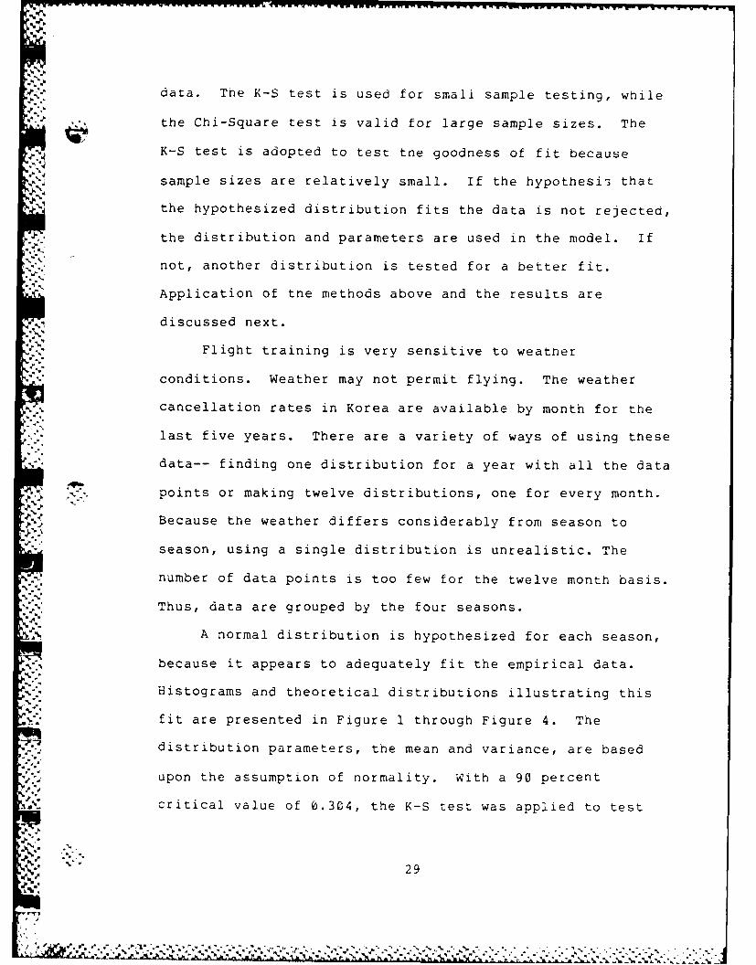
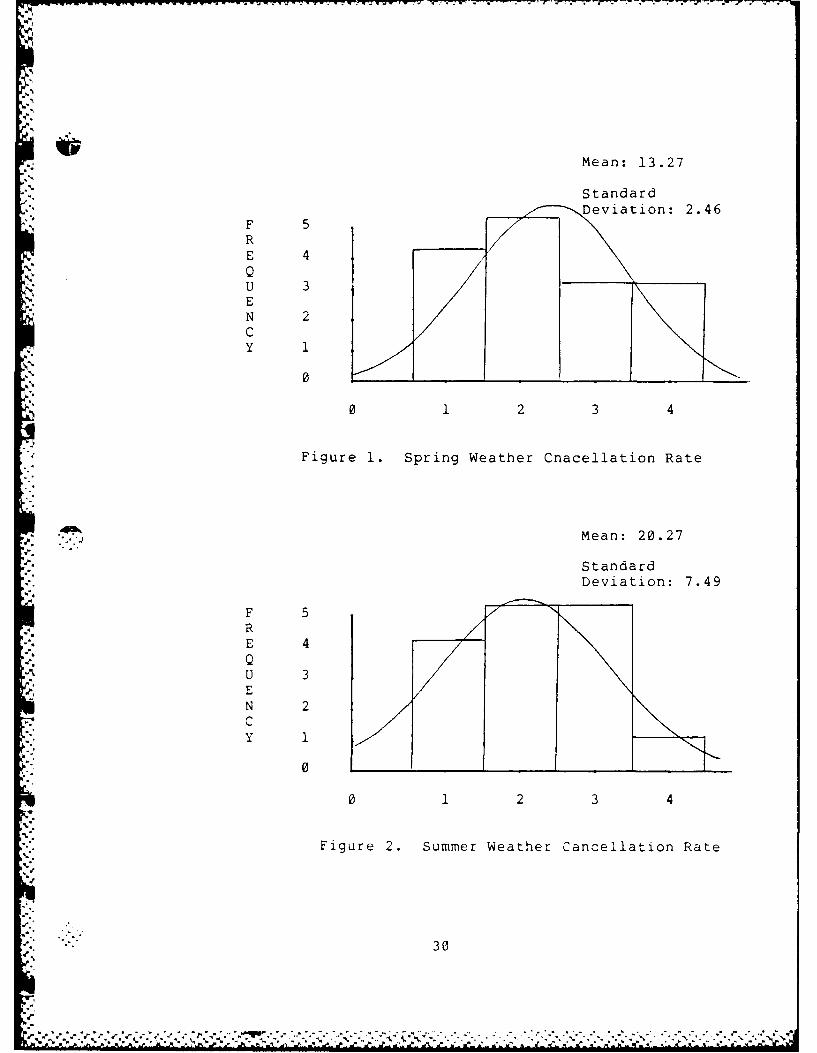
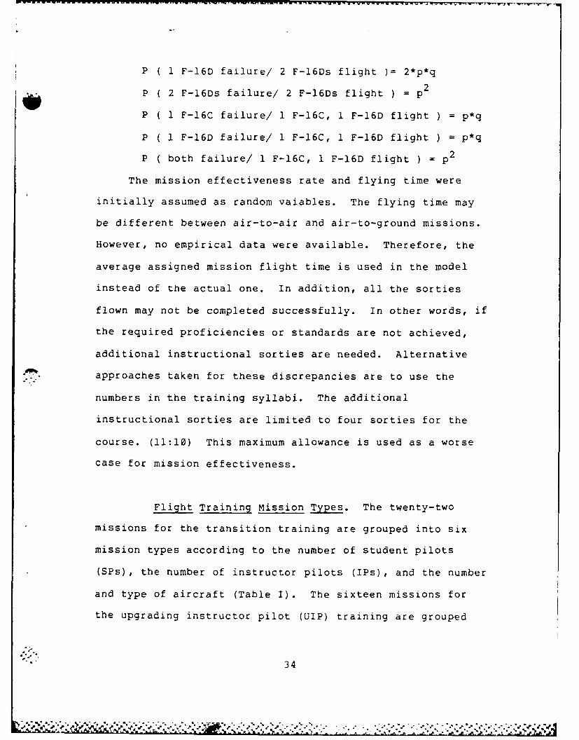
A normal distribution is hypothesized for each season,
because it appears to adequately fit the empirical data.
Histograms and theoretical distributions illustrating this
fit are presented in Figure 1 through Figure 4. The
distribution parameters, the mean and variance, are based
upon the assumption of normality. With a 90 percent
critical value of 0.304, the K-S test was applied to test
29
Mean: 13.27
StandardDeviation: 2.46
F 5RE 4QU 3|
EN 2CY 1
0
0 1 2 3 4
Figure 1. Spring Weather Cnacellation Rate
i* Mean: 20.27
StandardDeviation: 7.49
FRE 4QU 3EN 2CY 1
0 2 3 4
Figure 2. Summer Weather Cancellation Rate
30
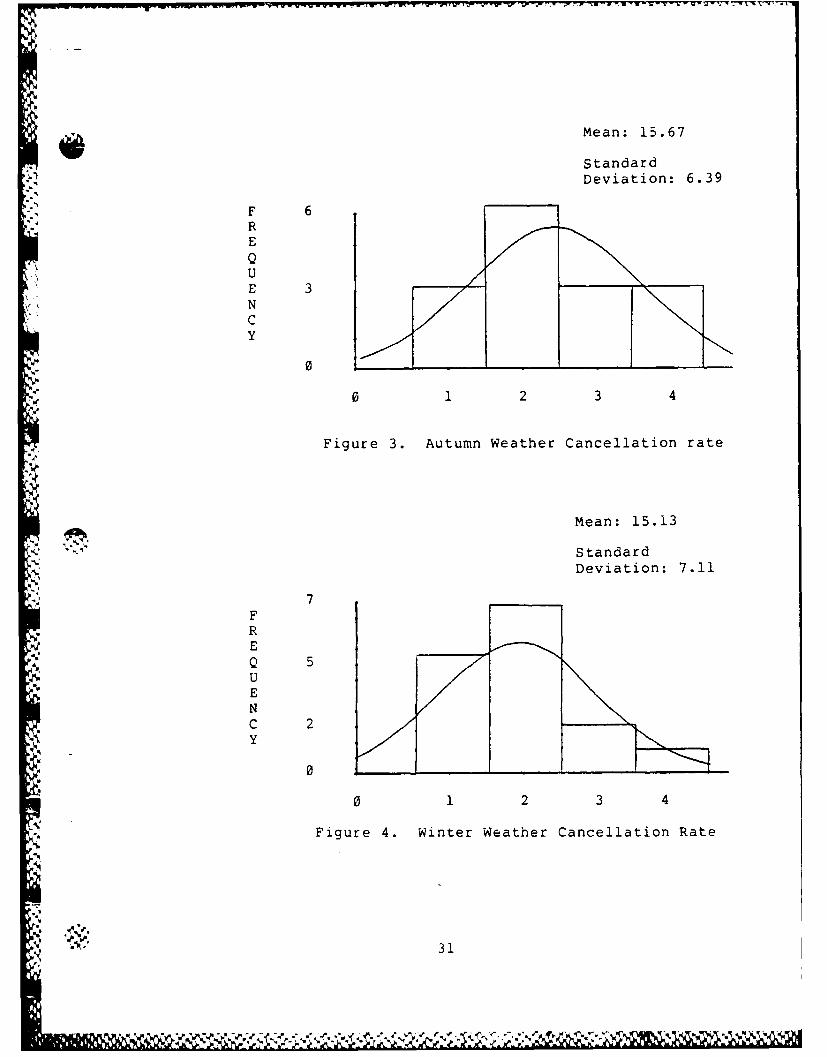
Mean: 15.67
StandardDeviation: 6.39
F 6REQUE 3NCy
0
0 1 2 3 4
Figure 3. Autumn Weather Cancellation rate
Mean: 15.13
StandardDeviation: 7.11
FRE
*4Q 5
NC 2y
0 _ _ _ _ _ _ _ _ _ _ _ _ _ _ _ _ _ _ _ _
0 1 2 3 4
Figure 4. Winter Weather Cancellation Rate
31
~ ~ *~*** ~ ,~/4/ LIM~

the hypotheses. The K-S test statistics are shown as
follows:
Seasons K-S Test Statistics
Autumn 0.1577
Winter 0.1633
Spring 0.1431
Summer 0.1142
Each statistic is less than the 90 percent critical value,
so the K-S test does not reject the hypothesis that each
weather cancellation rate is distributed normally.
The transition training and the UIP training do not
require night training. Thus, the sortie generation per
day is limited to daylight hours. The data on daylight
hours in Korea were gathered semi-monthly for one year.
Again a single distribution for the whole year does not
cover the deviations of each season. For this reason, a
four seasons approach is adopted like the weather
cancellation rate for each season. But, the daylight hours
of Summer and Winter have relatively very small variances
with means of 13.7 and 10.4, respectively. So these
variables are treated as constants, and only the daylight
hours of Autumn and Spring are treated further. It is
hypothesized that daylight hours of each season have a
underlying uniform probability distribution. Each K-S test
statistic is less than the 90% critical value (0.468) , so
the null hypotheses can not be rejected. The K-S test
statistics and estimated parameters are:
32

Season K-S Statistics Mean Standard Variance
Spring 0.333 12.0 0.5774
Autumn 0.1667 11.5 0.1667
Unfortunately, not many data points were gathered for
the maintenance support complex. Intuitively, the aircraft
sortie generation process has various underlying probability
distributions. The aircraft failures during preflight check
and post flight check, ground abort, and repair time are
random variables. Only average values for these random
variables were available. (13) The probabilities of
aircraft failure need to be considered carefully because the
aircraft resources are limited, and the number and type of
aircraft may affect the scheduling process. A student pilot
can not fly his mission successfully when one of the flight,
either instructor pilot or another student pilot and an
instructor pilot, is aborted. Only a dual seat F-16D with
an instructor can continue to fly, but the student still can
not meet the mission standards, and the mission is treated
as an additional one. If no spare aircraft are available
when the aircraft is broken, the flight aborts its mission.
The aircraft failure rates in a flight are binomially
distributed. Assuming the probability of failure for a
single F-16C or F-16D aircraft is p, the probabilities of
aircraft failure for various aircraft mission combinations
are as follows:
33
-------- ----- - - f .--
P ( 1 F-16D failure/ 2 F-16Ds flight )= 2*p*q
P ( 2 F-16Ds failure/ 2 F-16Ds flight ) = p2
P ( 1 F-16C failure/ 1 F-16C, 1 F-16D flight ) = p*q
P ( 1 F-16D failure/ 1 F-16C, 1 F-16D flight ) = p*q
P ( both failure/ 1 F-16C, 1 F-16D flight ) = p 2
The mission effectiveness rate and flying time were
initially assumed as random vaiables. The flying time may
be different between air-to-air and air-to-ground missions.
However, no empirical data were available. Therefore, the
average assigned mission flight time is used in the model
instead of the actual one. In addition, all the sorties
flown may not be completed successfully. In other words, if
the required proficiencies or standards are not achieved,
additional instructional sorties are needed. Alternative
approaches taken for these discrepancies are to use the
numbers in the training syllabi. The additional
instructional sorties are limited to four sorties for the
course. (11:10) This maximum allowance is used as a worse
case for mission effectiveness.
Flight Training Mission Types. The twenty-two
missions for the transition training are grouped into six
mission types according to the number of student pilots
(SPs), the number of instructor pilots (IPs), and the number
and type of aircraft (Table I). The sixteen missions for
the upgrading instructor pilot (UIP) training are grouped
34
,>.* , . .. p --- *. . .- . .. ., -p** -*~. ~ * 7
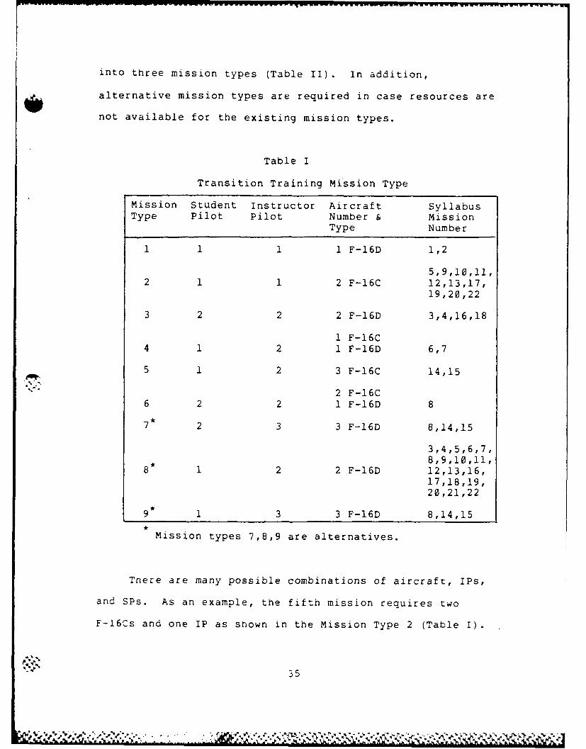
into three mission types (Table II). in addition,
alternative mission types are required in case resources are
not available for the existing mission types.
Table I
Transition Training Mission Type
Mission Student Instructor Aircraft SyllabusType Pilot Pilot Number & mission
Type Number
1 .1 1 1 F-16D 1,2
5,9,10,11,2 1 1 2 F-16C 12,13,17,
19,20,22
3 2 2 2 F-16D 3,4,16,18
1 F-16C4 1 2 1 F-16D 6,7
5 1 2 3 F-16C 14,15
2 F-16C6 2 2 1 F-16D 8
7* 2 3 3 F-16D 8,14,15
3,4,5,6,7,
8* 12 2 -16D8,9,10,11,8 1 2 F16D12,13,16,
17,18,19,20,21,22
9 13 3 F-16D 8,14,15
Mission types 7,8,9 are alternatives.
Tnere are many possible combinations of aircraft, IPs,
and SPs. As an example, the fifth mission requires two
F-16Cs and one IP as shown in the Mission Type 2 (Table I).
~. ~ C C ~ )5

Table II
UIP Training Mission Type
Mission Student Instructor Aircraft Syllabus
Type Pilot Pilot Number & MissionType Number
1 F-16C 3,4,5,6,1 2 1 1 F-16D 10,11,14
1,2,3,4,5,2 2 2 2 F-16D 6,10,11,12,
13,15,16
2 F-16C3 2 2 1 F-16D 7,8,9
1 F-16C 3,4,5,6,10,4* 1 2 1 F-16D 11,14
1,2,3,4,5,5 1 2 2 F-16D 8,9,10,11,
13,14,15,16
Mission Types 4 and 5 and Mission Numbers 3, 4, 5,
6, 10, and 11 in Mission Type 2 are alternatives.
The students follow the syllabus as strictly as possible,
but if no F-16Cs are available or only one F-16C is
available, then what should be done? This mission may be
replaced with one F-16C and one F-16D, or two F-16Ds.
Before the solo flight (fifth mission), the dual-seat F-16D
can not be replaced with the single-seat F-16C. For flying
safety reasons, only the single seat F-16C may be replaced
with the dual seat F-16D if necessary. As another example,
the third mission consists of two SPs, two IPs, and two F-
16Ds as shown in Mission Type 3 (Taole I). If all SPs have
completed the third mission except one, then the last SP has
36
- ~-------- '~7, r r. ~
no partner to fly the third mission. The third mission of
the last SP can be changed to another one which consists of
only one SP with the same mission tasks. In this case the
alternative is Mission Type 8 which consists of one SP, two
IPs, and two F-16Ds. For this study, the alternatives are
consolidated as discussed above. The Mission Types 7, 8,
and 9 in Table I are provided as alternatives for transition
training and the Mission Types 4 and 5 in Table II are
alternatives for UIP training. The primary mission types
and alternatives for transition and UIP training are shown
in the Table I and II.
Model Assumptions. The following assumptions are used
in the model:
1. The proposed F-16 squadron structure represents the
one which will be created.
2. No simulator is used for training. The ROKAF is
considering a plan of sharing the USAF simulator at Kunsan
Air Base, Korea. But, even if it is possible, the simulator
training will not be given during the flying training.
3. There may be differences between the USAF
maintenance support ability and the ROKAF ability. The
aircraft failure rate of F-16C/D is worse than the rate of
F-16A/B. But only F-16A/B data obtained from the USAF are
used in the model.
<'/ 37T

5. Support personnel, materials, and facilities are
assumed to be sufficient to support the flying and academic
training.
6. The student attrition rates are not considered.
Because the entry prerequisites are very tight and the ROFAF
selects highly experienced pilots as students, the student
attrition rates are expected to be negligible.
7. The weather conditions may vary considerably from
minute to minute. Because the flying training requires good
weather condition from one hour before takeoff to one hour
after landing, it is assumed that the weather conditions are
checked every four hours.
8. The possible alternative mission types are limited
to the substitution of F-l6Cs for F-l6Ds and the replacement
of the mission types requiring two SPs with the mission
types requiring one SP.
9. The UIP academic training during the flying
training period requires sixteen hours. Thus, two more
preflight academic training days are added.
Model Building. The model can be divided into
three sections, i.e. transition training, UIP training, and
subroutines common to transition and UIP training such as
academic training, weather cancellation, daylight hours,
postflight check, weather abort, aircraft failure, and
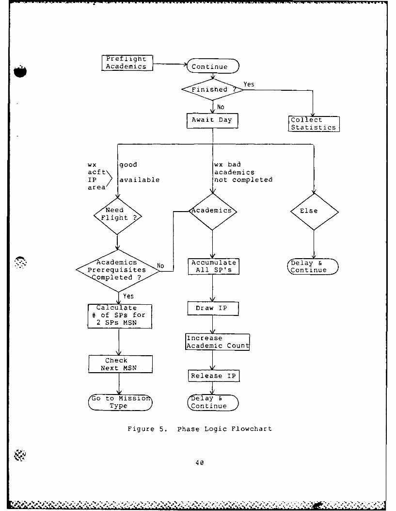
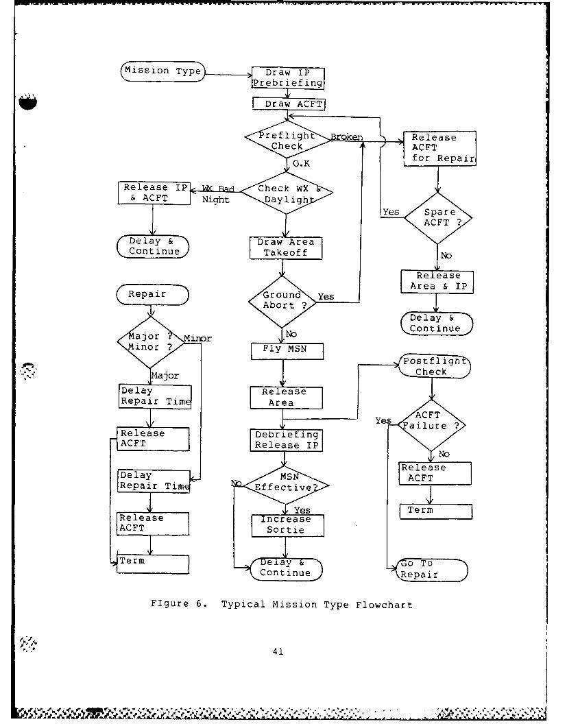
aircraft repair subroutines. The mathematical model (Figure
5 and 6) and the computer source code listing (Appendix F)
38

are referred to in tne following discussions of the
program's operation. The SLAM network model starts
processing with the creation of students. Two separate
creations produce transition training student pilots and
UIPs. A dummy entity created at the same time is used for
changing the instructor pilots during the ground training
days, changing the allocated aircraft resources, and
assigning class numbers. The transition training module,
the UIP training module, and other modules are discussed in
detail along with the general flow of the model.
Transition Training Module.
General. Once the student pilots are created,
they take preflight academic training and are each assigned
the following attributes: sorties flown, academic hours
trained, and starting day of flight training. The ground
training for the transition course takes nineteen days and
involves ninety academic hours. The preflight academics do
not cover all academics required. The remaining hours are
spread evenly over the flying training period.
39
PrefaightAcademics Continue
Statitc
wx Igood wx bad
acf t~ academicsrIPea >available not completed
Need cademics ElseFlight ?
cademics Accumulate DelayP r e o C o t i n u
rerequisites All SP'sContinueompleted ?/
,,YesCalculate Draw IP
# of SPs for2 SPs MSN
i~IncreaseCon
IAcademic o n
NetMSN IRelea e IP]
_0 4 tO Misnsio (celay &
Type Continue
Figure 5. Phase Logic Flowchart
40
P 9 '5% .." , % ., " ., .w " " ..." .", " .% ."% , " " , .." .". " " " " " " " " " " " ' " " " " " 1, '
Misn Tyer
rlg kReleaseDere nACFheas IPF
Repair Tir Repatiie
Release n-a hcrkas
ACFT Sorti
Temy e Day AreoaT
CotneTofnu Reai
F~gre .Tpicl isson ypeFlochrla
-'
IVe
&
Repai Grud eAAbor41

After the completion of preflight academics, tiie
students start transition flying training. if the syllabus
requirements are not complete, the students proceed to the
next activity. A student usually flies a mission a day.
(11:26)
The student are scheduled academics, flying, or delayed
depending upon weather conditions and availability of
instructor pilots, aircraft, and areas. The students
scheduled for flying are checked to determine whether the
academic prerequisites are completed.
Checking Academic Prerequisites. At this point,
some necessary modifications need to be discussed. The
academic training during each flying period is grok.Jed into
flying training modules. As mentioned earlier, a new module
has specific academic prerequisites. In no case does flight
training precede the related ground training. The academics
of the same module are grouped together and completed before
the new module starts so that the program does not violate
SLAM language's upper bound limitation on statistical
arrays.
Selecting Mission Type. If all academic
prerequisites are complete, then the students check how many
students pilots have completed for the missions requiring
two students pilots. As previously explained, if no partner
is left to fly with him, the student selects an alternative
42

mission type which consists of one SP with the same tasks.
The students are scheduled according to the sorties flown,
the remaining aircraft resources, and other prescribed
conditions.
Typical mission Type. Once the mission type is
chosen, the students are scheduled for the appropriate
mission type. Every mission type has similar structure with
the execption of resource requirements such as IPs, and
number and type of aircraft. After assigning the mission
type, if two student pilots are needed, the first student
waits until a second student pilot requiring the same
mission comes along.
The typical mission training process, as previously
discussed, starts with a preflight briefing with the
instructor. After the aircraft are assigned, the 30-minute
preflight check is conducted. If the aircraft pass the
preflight check, the students check the weather and daylight
again and taxi out for take off. If the aircraft are not
ground aborted, the missions are flown. The aircraft are
branched to postflight check after the mission and the
students conduct the one-hour debriefing. Next a check for
completion of syllabus requirements is performed.
Academic Training. The students are scheduled for
academic training in order to satisfy prerequisites for the
next mission, in case of bad weather, to prepare for
missions beyond the next one, or for review if all academic
43
training has been acomplished. If the students have taken
eight hours of academics they are branched back to a
continuing node. If not, the students await the academic
training gate which will be open when all SPs are gathered
or the night comes. When the night comes after all SPs are
gathered, they return to a continuing node. The last SP
closes the academic training gate after all SPs pass the
gate. The students draw one IP, take one hour of academic
training, and increase the academic training counter. Then
they return to a continuing node.
UIP Training Module.
General. The UIPs are created from the second
transition training class on. A dummy entity is used for
altering an IP resource during preflight academic training
and assigning the class number. The ground training for the
UIP course takes five days and requires twenty-two academic
hours. The additional sixteen hours of required academics
are included by adding two more ground training days because
of the SLAM statistical array limitation. The UIPs are
assinged the values of sorties flown, academic hours taken,
class number.
Next, the program checks if UIPs have completed their
flying training and academic training. When day comes, the
UIPs are branched to flying training depending on the
weather conditions and availability of IPs and aircraft.
Otherwise, the UIPs are delayed and continued.
44
PIP Ar...
Selecting Mission Type. The UIPs check the
weather conditions and available resources for flying. If
these conditions permit flying, then the tJIPs check how many
UIPs have completed the missions requiring two UIPs in order
to decide whether to select an alternative mission type or
not. Then the UIPs select a mission type according to
sorties flown, resources available, and prescribed
conditions.
The UIP mission types, except the first one, are the
same as the ones in transition training. After assigning
the mission type, the UIPs are branched to the same mission
type module for transition training. After the flights,
the program returns to UIP mission type, checks if the
mission is effective, and adjusts their sortie counters for
the UIP as appropriates.
other Modules.
Weather Cancellation Subroutine. A weather
cancellation rate is drawn from a probability distribution
in a FORTRAN program. If the weather is bad, the weather
gate is closed for four hours. The FORTRAN event subroutine
releases the students waiting IPs, or another SPs in a file.
Then the weather cancellation rate is drawn again.
Daylight Subroutine. First the day gate is open.
At the same time the academic training gate is closed for
45

gatnering all SPs, if necessary. Then the daylight hour is
drawn using a FORTRAN subroutine. After the daytime, the
daylight gate is closed, and the daily counters are reset to
zero. Again the FORTRAN event subroutines remove the SPS
awaiting IPs or other SPs from a queue and file them in the
await day queue. The academic training gate is opened in
order to return the SPs at the awaiting academic training
gate.
Weather Abort Subroutines. If the weather is bad
or night comes before takeoff, the students release all the
resources grasped, return to the starting point, and wait
for daylight hours or are branched to academic training.
Aircraft Failure Subroutines. These subroutines
are used for releasing failed aircraft for repair and
drawing spare aircraft if available. When aircraft failures
occur during preflight check or aircraft are ground aborted,
the failed aircraft are released for repair. The students
then check whether spare aircraft are available. If
available, the students draw the spare aircraft, perform the
preflight check, and continue the mission. If not, the
students release all the assigned IP's, aircraft, and areas.
They are delayed for three hours and then continue.
Postflight Check Subroutines. The 30-minute
aircraft post flight check is performed by the maintenance
crew. Failed aircraft are sent to the repair subroutine.
If the aircraft is not broken, it is released to aircraft
resources.
46
Aircraft Repair Subroutines. All failed aicraft
sent from preflight check, ground abort, and postflight
check are repaired in two subroutines for major repair and
minor repair. After an aircraft is repaired, it is returned
as a resource available for flying.
All these relationships described above are translated
into a SLAM network simulation model. Appendix F lists the
complete SLAM source code, and Appendix G contains FORTRAN
subroutines which compute the weather cancellation rate and
daylight hours. A FORTRAN subroutine also insures that the
student pilots waiting either for IPs or other SPs go back
to the awaiting day node.
Verification
Verification is the process of assuring that the
simulation program actually behaves as the programmer
intended. Verification is the comparison of the conceptual
model to the computer code to see if the code accurately
reflects the flow and logic of the conceptual model. (1:375)
The more complex a model is, the more time consuming the
verification process is. There are many ways to attempt to
reduce the potential frustration of verification. Some of
these techniques are (1:375-379):
1. Program the system module by module. Before adding
a new module to the main program, check to see if a module
behaves correctly.
v~t 47

2. A flow diagram of the conceptual model provides a
good method for checking the logic flow.
3. Have other programmers check the code.
4. Careful examinations of output checks the
reasonableness of the modules.
5. Adequate documentation of the code makes tracking-
down errors easier.
Flowcharts of the logic flow were prepared for major
program modules. An example of the flowcharts is given in
Figure 5. The purpose of this is to prevent logic errors in
the program. Logic errors are the most difficult to find.
The flowcharts were most helpful in checking all possible
logic paths.
Whenever a new module is added to the main program, the
output result was investigated. The reasonableness of the
printouts was verified by checking the SLAM trace outputs.
The full documentation was a great aid in detecting errors.
All techniques discussed above were used for model
verification.
Val idation
Validation is the overall process of comparing the
model and its behavior to the real system. Because far
reaching decisions may be made on the basis of simulation
results, validation of simulation models is of great
importance, The subtle difference between verification and
.2 48
F--, .,-.--. ..- - - - - ..- F, *-~~ .4 IA- . . - . - ..... -V '

validation is that the former is the comparison of a model
to the designer's intentions while the latter is the overall
comparison of a model to the real system. The model
calibration process takes a major part of validation. The
model results are compared to expected results of the
proposed system and adjustments are made if necessary. An
iterative process of calibrating a model increases the
model's accuracy. (1:383-387)
As an example, in early runs of the model the UIP
classes were finishing their training too quickly. When the
trace outputs were checked, it was found that they were
flying twice a day. A modification was made to allow only
one sortie per day. This calibration made the model output
more closely match the recommended number of training days
in the syllabus.
The validation process was very difficult in this study
because the ROKAF has no experience with F-16 training. The
lack of historical data does not allow full validation of
the model. Thus, after running the simulation with
estimated values, the output of the model was compared with
the values the training syllabi recommend.
The following steps are recommended aids in the
validation process: 1. Check the model for face validity.
2. Validate the data assumptions and structural
assumptions. High face validity is obtained with the
assistance of potential users and other knowledgeable
49

persons' inputs. All the data and operational structures
were gathered from the planners; the output of the model was
evaluated for reasonableness by the planners. These
processes increased the face validity of the model.
Reliable data and correct statistical analyses of the data
validate the data assumptions. Structural assumptions are
validated by actual observations. For full validation the
model still requires better historical data.
Summary
The discussion of the F-16 training environment
includes the proposed F-16 squadron structure and training
process. The squadron structure explicitly represents the
status of the training situation, the number of transition
student pilots, UIP's, aircraft allocated, areas available,
and the number of classes to be trained. The training
process represents the academic and flying training
requirements of both courses. Furthermore, the training
flow, scheduling of flight operations, and the typical
training mission are discussed in detail. The review of
squadron structure and training process identifies various
components and variables. From the components identified
the input variables and other random variables are
extracted.
After fully understanding the system operation, a SLAM
model is constructed. The-major sources of the data are
50

ROKAF/HQ, USAF/ASD, ILC, and TAC. Not enougn data exist for
full development of the random variables. The information
from the syllabi and the average values for the maintenance
system variables are used for the random variables on which
data are not yet available.
A variety of model assumptions were used in the model
construction. Certain simplifying assumptions were made to
insure the whole program did not violate the upper bound of
SLAM statistical arrays. The primary syllabi instructions
and its alternatives increase the realism of the program.
Finally, verification and validation of the model are
discussed. Programming module by module and checking the
trace output are time-consuming processes, but all the
efforts taken ensure the model behaves as intended.
J,. Validation was very difficult because the F-16 training
system is a proposed one for the ROKAF. Close cooperation
with the planners improved face validity, but the model
still requires more data for full validation.
51
IV. Experimental Design
Introduction
This chapter discusses the experimental design of the
model. The independent variables or factors are selected
and investigated in the experimental design. The factor
levels are chosen from expected levels by the planner. The
responses to be measured are also chosen to provide
information about the research questions. Then, the choice
of experimental design is discussed, followed by the number
of runs and sample sizes.
Selection of Factors
The model variables which could be used as factors in
the experimental design are shown in Table III. The
controllable variables can be divided into two major
categories: the syllabus requirements and resource factors
related to the implementation plan. The syllabus
requirements for transition (TX) and UIP are number of
flying sorties and academic training hours. Because these
requirements were designed specifically to produce qualified
pilots, it does not seem reasonable to vary these
requirements. The other factors are number of SPs, number
of IPs, number and type of aircraft (ACFT), and number of
airwork areas. The ROKAF has tenatively assigned the number
of SPs and the resources, IPs, F-16Cs, F-16Ds, and areas.
52

Table III
Model Variables
Controllable Variables Random Variables
SPs per Class Weather Cancellation Rate
UIPs per Class Daylight Hours
SPs per Class Preflight Check Failue Rate
Flying Sortie for TX Postflight Check Failure Rate
Flying Sortie for UIP Ground Abort Rate
Academic Hours for TX ACFT Repair Time
Academic Hours for UIP Mission Effectiveness Rate
Number and Type of ACFT Flying Time
Number of Airwork Areas
Since the ROKAF's primary concern during the F-16
implementation is producing F-16 pilots as soon as possible,
uncertainties about these factor levels appear to be worth
investigating. For example, various possible allocations of
the limited number of dual seat aircraft among basic
transition, UIP training, and tne graduate training should
be investigated.
The factors initially chosen for the experiment are the
IPs, F-16Cs, F-16Ds, and areas. But, of these factors the
number of iPs and areas appeared not to affect the overall
training process in the first experiment. One more IP has a
statistical significant effect on the system responses. The
53

average number of days to complete the entire training,
transition and UIP training are reduced by one or two, which
may not important in practical sense. Once the UIPs are
trained, they are put into graduate pilot training, but can
be converted to transition and UIP training anytime.
Decreasing one airwork area does not affect the system
responses. The test statistics (F-values) are ranging
0.0018 to 0.3537, which can not reject the hypothesis or the
equality of cell means. The average utilization of each
airwork area in the computer output was very low, the
average of 0.12. For these reasons, a second selection was
attempted. The number of transition student pilots and
aircraft failure rates was considered instead of the IPs and
areas.
Furthermore, of the random or uncontrollable
variables the aircraft failure rates and ground abort rates
have the potential to seriously affect the training
environment and interact with other factors. The data used
in the baseline model runs for ground aircraft failure rates
and abort rates was for the F-16A/B. The F-16C/D has
significantly worse failure and ground abort rates, which
may have a serious effect on overall the system performance.
But actual data were not available. Therefore, the aircraft
failure rates and ground abort rates are grouped and
selected as a factor in the experimental design.
54

Choice of Factor Levels
An overall investigation of selected factors identifies
which factors have significant effect on the F-16
implementation and if any significant interactions exist
among the factors. An interaction exists between factors
when the difference in response between the levels of one
factor is not the same at all levels of the other factors.
If an interaction effect is large, the corresponding main
effects have less practical meaning. Two levels of each
factor spanning the range of likely values are enough to
analyze all these interactions.
Two levels for each factor are defined as Level I and
Level II. Level I is a baseline level for each factor- the
resource level initially allocated by the ROKAF or mean
aircraft failure rate and ground abort rate. Level II is
the resource factor level expected by the planner or the
highest expected aircraft failure rate and ground abort rate
which doubles the baseline failure and abort rate.
The possible changes of aircraft resources do not cover
the whole training period. There is no choice in changing
aircraft number and type until more aircraft are delivered.
After the F-l6Cs' arrival, one more F-16C can be allocated
for the transition and UIP training and one F-16D can be
transferred to graduate training. One more SP can be
trained in each class, which will compress eight transition
classes to seven classes. The aircraft failure rates and
55
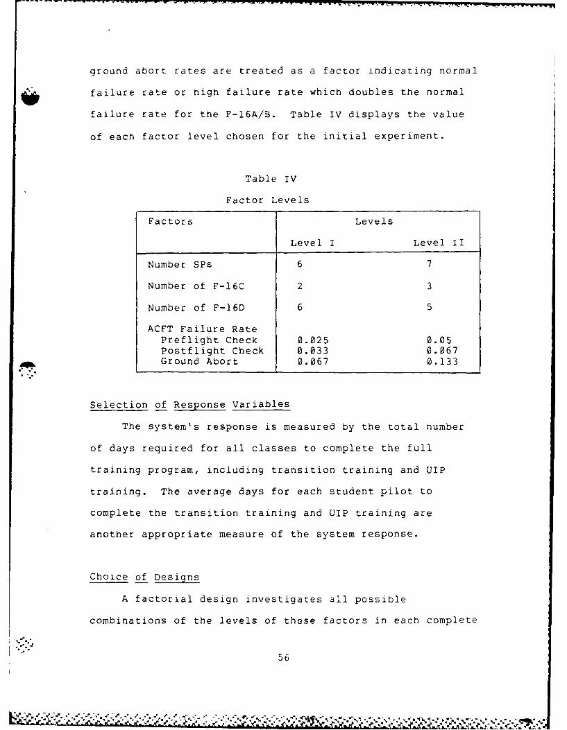
ground abort rates are treated as a factor indicating normal
failure rate or nigh failure rate which doubles the normal
failure rate for the F-l6A/B. Table IV displays the value
of each factor level chosen for the initial experiment.
Table IV
Factor Levels
Factors Levels
Level I Level II
Number SPs 6 7
Number of F-16C 2 3
Number of F-16D 6 5
ACFT Failure RatePreflight Check 0.025 0.05Postflight Check 0.033 0.067Ground Abort 0.067 0.133
Selection of. Response Variables
The system's response is measured by the total number
of days required for all classes to complete the full
training program, including transition training and UIP
training. The average days for each student pilot to
complete the transition training and UIP training are
another appropriate measure of the system response.
Choice of Designs
A factorial design investigates all possible
combinations of the levels of these factors in each complete
56

trial or replication of the experiment. The change in the
response variables due to a change in the levels of a factor
and the interaction among factors are estimated at different
levels of the factors.J
As discussed above, the two levels allow 2kfactorials
which provide the smallest number of treatment combinations
with k factors for a complete factorial arrangement. (6:189-
192; 261-262) A full factorial analysis of the four factors
chosen, each at two levels, requires 2 , or 16 runs. The
full factorial design matrix is shown in Table V.
Run Length and Number of Replications
The technique used in the F-16 training model was to
start the simulation with no classes in training. Classes
begin its training every three months. After the desired
number of pilots are produced, the program automatically
stops. There is no inadvertent bias resulting from when the
system starts, and the steady state characteristics are not
of interest. Thus, determination of run length and starts
of the steady state operation are not of major concern.
57

Table V Design Matrix
Run Level I Level II
a b c d A B C D
1 * * * *
2 * * * *
3 * * **
4 * * **
56 * * *
67 * * *
78 * * *
9 * * **
10 * * * *
11i * * *
12 * * * *
13 * ** *
14 * * **
15 ** * *
16 * * * *
where, a: 6 SPsb: 2 F-16Csc: 6 F-16Ds0: average aircraft failure rateA : 7 SPsB: 3 F-160s (from mid-second class)C: 5 F-16Ds (from mid-second class)D: high aircraft failure rate
58
% i i ',. X ",- - . S'L' ,. ' ; -''' - .". _. -"- -" . . ' ' " -. "-"-" ' .-.-.- - """": "- """ " " 2 " " "

- rw rflfl. fl~~~~r~ C' CN~~fl WW!VWW,~ . -VI -I iF WW I WWV . W. . r V W W*W W'r. N U-, C -
But, the number of replications is very important to
the accuracy of the results. A replication is a repetition
of the basic experiment. W~ith these replications, an
estimate of the experimental error is obtained and becomes a
basic unit of measurement for determining whether the
observed data are really statistically significant. The
more replications, the closer the estimates for the
population.
Four factors were considered for the F-16
implementation process. Two factor levels for each factor
and full factorial design requires 2 , 16 runs for each
replication. The complete factorial experiment includes all
combinations of the levels of the factors taking one level
of each factor.
After the number of runs is determined, the next step
is to determine how many replications are needed for each
run. This depends on the the desired sensitivity ar long as
the estimate is not seriously biased. To identify the full
interaction between the factors, the multivariate analysis
of variance techniques are used which require at least one
more replication than the number of response variables.
(4:213) Four replications for each run totals 64
replications.
The linear model for the full factorial design of the
four factors is as follows:

Response = Mean + Main Effects + Interaction Effects + Error
The interaction effects consist of two-factor interactions,
tnree-factor interactions, and the interaction of all four
factors. The difference between the model response value
and the mean is due to the effect of factors, the
interaction effects and the experimental errors. The
coefficients, or slopes, of the main effect terms and the
interaction terms represent the average change in response,
respectively. The statistical significance of the factors
and the interactions is analyzed in Chapter V from the
experimental results by using the analysis of variance
technique.
Summa rv
Of the model variables, the number of student pilots,
the type and number of aircraft, and the failure rate of
aircraft were selected as factors for the experimental
design. The aircraft failure rate, even though
uncontrollable, was chosen as a factor because of tight
aircraft resources. The factor levels were determined based
on possible scenarios of interest to the planners.
A complete factorial design was adopted because the
interactions between all factors are of interest and the 2
60

factorials require only 16 computer runs. The response
variables are the number of days required for total
completion of training and the number of days taken for
transition and UIP training for each student pilot. The
experimental design involves four replications for each
factor combination, requiring 64 replications. Finally, the
linear statistical model to be used to analyze the results
was presented.
V. Analysis of Experimental Design
introduction
This chapter discusses the results of the experimental
design using the univariate and multivariate analysis of
variance. The basic questions to be answered concern how
each factor affects the days to complete the entire training
program and the days required for transition training and
upgrading instructor pilot training and if any, how the
factors interact to influence the response variables. The
one way analyses of variance reveal whether the difference
between factor levels for each factor is statistically
significant or not. The multivariate analyses of variance
provide information about interactions among the factors.
Finally, sensitivity analyses are conducted to determine how
sensitive the system is to factors identified as being
significant.
Analysis
Main Effects for Average Days to Complete Total
Training. In the first experiment, the number of IPs has a
weak significance (F-value: 4.9, tail probability: 0.3 on
average days to complete the entire training. The number of
areas are not significant with the tail probability of 0.97.
The statistical results for the second experiment are found
62

in Table VI and Appendix C. The number of transition
student pilots in each class has a statistically sign4ificant
effect on the average number of days needed to complete the
total training, while the number of F-16Cs, the number of F-
16Ds, and the aircraft failure rate do not. The test
statistics show no significant difference between the factor
levels. Nevertheless, the mean delay for five F-16Ds, and
high aircraft failure rates are six and ten days,
respectively, which may be an important practical
consideration. Table VI shows the values for the effect of
each factor and two factor interactions for the response
variable, the days to complete entire training. The
descriptive analyses of these factors are represented in
Figure 7a through 7d. The main effects for each factor are
explained further in the following paragraphs.
Changing the number of transition student pilots in
each class from six to seven has important significance.
Increasing the number of student pilots by one in each class
compresses the total training from eight classes to seven
and reduces the total training days by 61.3. This result
reveals that one more student can be trained with the
resources allocated.
63
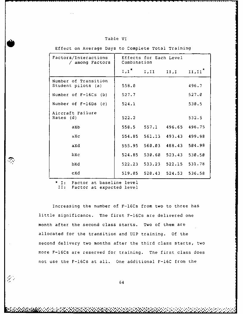
Table VI
Effect on Average Days to Complete Total Training
Factors/Interactions Effects for Each Level/ among Factors Combination
Number of TransitionStudent pilots (a) 558.0 496.7
Number of F-16Cs (b) 527.7 527.0
Number of F-16Ds (c) 524.1 530.5
Aircraft FailureRates (d) 522.2 532.5
aXb 558.5 557.1 496.65 496.75
aXc 554.85 561.13 493.43 499.98
aXd 555.95 560.03 488.43 504.98
bXc 524.85 530.60 523.43 530.50
bXd 522.23 533.23 522.15 531.78
cXd 519.85 528.43 524.53 536.58
• I: Factor at baseline levelII: Factor at expected level
Increasing the number of F-16Cs from two to three has
little significance. The first F-16Cs are delivered one
month after the second class starts. Two of them are
allocated for the transition and UIP training. Of the
second delivery two months after the third class starts, two
more F-16Cs are reserved for training. The first class does
not use the F-16Cs at all. One additional F-16C from the
64

560 560
540 540
520 520
500 500
480 480
1* 1I* I II
a. Number of Students b. Number of F-16Cs
560 560
540 540
520 520
500 500
480 480
I II I II
c. Number of F-16Ds d. ACFT Failure Rate
* I: Factor at baseline level
II: Factor at expected level
Figure 7. Main Effects on Average Daysto Complete Total Training
65

560 560
Number 540 Number 540of of
F-16Cs 520 F-16Ds 520
500 500
480 480
I* II* I II
a. Number of Students b. Number of Students
560 560
ACF'k 540 Number 540F.ilure ofRates 520 F-16Ds 520
500 500
480 480I II I II
c. Number of Students d. Number of F-16Cs
560 560
ACFT 540 ACFT 540Failure Failure
Rate 520 Rate 520
500 500
480 .- 480
I II I II
e. Number of F-16Cs f. Number of F-16Ds
*1: Factor at baseline level II: Factor at expected level
Figure 8. Interaction Effects on Average Dayto Complete Total Training
66

first F-l6C"s arrival on does not affect the total number of
training days. This is to be expected because the
alternative mission types are based on the substitution of
the F-l6Ds for the F-l6Cs.
Decreasing the number of F-16DS from six to five does
not have a statistically significant impact on the response
variables. It increases by six the number of days to
complete training. Each new class enters transition and UIP
training every three months. The transition class has
nineteen days of preflight academics and the UIP class seven
days. The former class can catch up its training and can
even accomplish remaining syllabus requirements during the
ground academic training period for the class following it
in case of delays. For this reason, the delays for a class
that push it a few days into the next class do not affect
the overall results. This explains why the number of F-16DS
does not affect the response variable so long as there are
no excessive delays.
The aircraft failure rate is not statistically
significant with respect to the average days to complete the
total training even when the rates are doubled. High
aircraft failure rates increase the total training days by
an average of ten days which is only about a two percentage
increase. Here the same arguments apply as the effects of
the number of F-l6Ds. The ground training days probably
cover the accumulated delays for the total completion.
67
Significant Interaction Effects on Average Days to
Complete Total Training. The interactions among the factors
are discussed using the descriptive figures and the test
statistics. The F-values in Appendix D-6 show that only the
interactions between the number of student pilots and the
aircraft failure rates and between the number of F-l6Ds and
the aircraft failure rates are significant. Adding one more
transition student pilot in each class, places a greater
demand on the limited resources such as IPs, types and
numbers of aircraft, and areas. This added demand delays
the training and increases the number of days. Also, the
high aircraft failure rate results in lower aircraft
availability. As Figure 8a through 8f show, the seven
transition students interaction with the high aircraft
failure rates result in more increased total completion days
from 488.4 to 505 rather than from 556 to 560 (Table VI).
Another significant interaction is the one between the
F-l6Ds and the aircraft failure rate. The main effects of
these factors are not significant. However, changing these
factor levels increases the total number of days for
training by six and ten days, respectively. The decreased
number of F-l6Ds coupled with the high aircraft failure
rates interacts with each otner because the training is
highly dependent on the dual seat F-l6Ds. Yet, the increase
68

is only about ten days or about two percent. Practically
speaking, this is probably not significant.
Main Effects for Averag taso Compete Transition
Training. The transition training is a more important
factor in determining the total days to complete the
training than UIP training because the UIP training is
shorter. In addition, because of short time, one UIP class
may affect a transition training class but not another UIP
class. Except for the F-l6Cs, all other factors appear to
be significant with respect to the average number of days to
complete the transition training. Table VII, Figure 9a
through 9d, and Appendix C are referred to in the following
discussions.
Adding one transition student in each class delays the
average transition training by 9.9 days. This means one
more student pilot can be trained with the resources
allocated, with a thirteen percent increase in average
number of days over the time it takes to train six student
pilots. But the total training days for all classes can be
reduced by about three months because it eliminates the need
for the last class. in other words, each student pilot
takes ten more days to complete the transition training, but
the days to produce the desired number of F-16 pilots are
decreased considerably. Ten more days for each student
pilot to complete transition training represent significant
delay, but decreusing total training days by 61.3 which
69

Table VII
Effect for Days to Complete Transition Training
Factors/Interactions Efects for Each
/ among Factors Combination
II III III 11,I1
Number of TransitionStudent pilots (a) 74.41 84.27
Number of F-16Cs (b) 79.21 79.47
Number of F-16Ds (c) 75.76 82.91
Aircraft FailureRates (d) 74.62 84.05
aXb 74.30 74.50 84.10 84.44
aXc 71.56 77.55 79.96 88.58
aXd 71.15 77.66 78.10 90.45
bXc 76.26 82.16 75.27 83.67
bXd 74.46 84.15 74.79 82.71
cXd 71.42 80.11 77.83 88.00
equates to three working month, seems to be more important
to the planners.
Losing one F-16D after the first F-16Cs' delivery
delays the transition training by an average of 7.1 days,
which is statistically significant. The reduced number of
F-16Ds degrade the sortie generation capabilities and
increase the training days.
70

90 90
85 85
80 80
75 75
70 70
I II III
a. Number of Students b. Number of F-16Cs
90 90
85 85
80 80
75 75
70 70
I II I II
c. Number of F-i6Ds d. ACFT Failure Rate
* I: Factor at baseline level
II: Facotr at expected level
Figure 9. Main Effects on Average Daysto Complete Transition Training
71
% Lt i~~a $J* .% % 2 l -
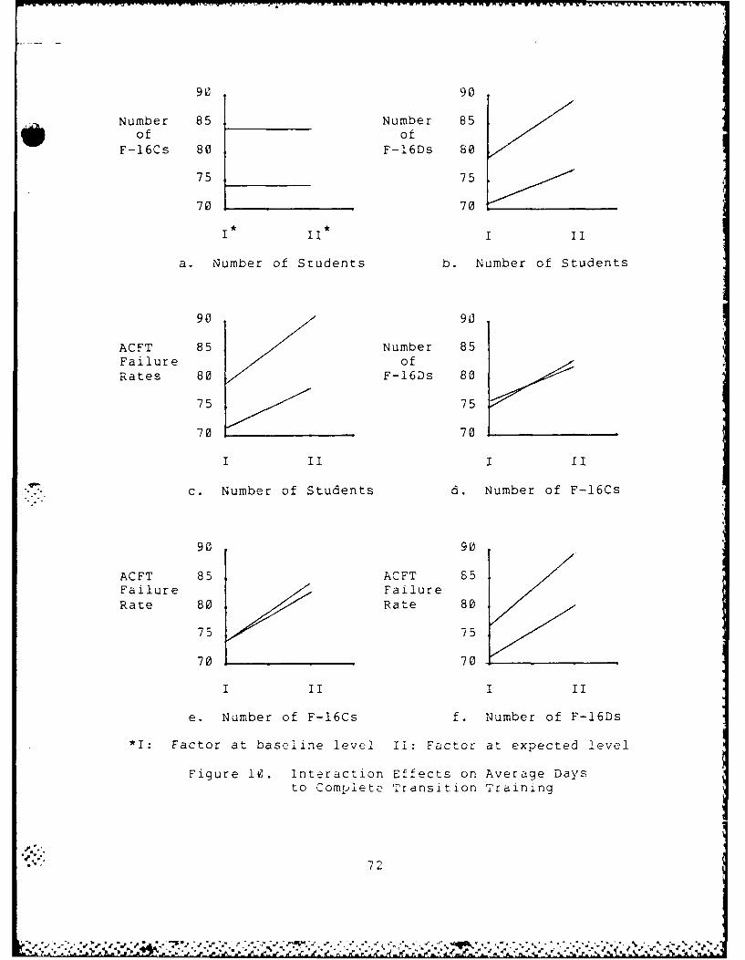
90 90
Number 85 Number 85e of ofF-16Cs 80 F-16Ds 80
75 75
70 70
I II I II
a. Number of Students b. Number of Students
90 90
ACFT 85 Number 85Failure ofRates 80 F-16Ds 80
75 75
70 70
I II I II
c. Number of Students d. Number of F-16Cs
90 90
ACFT 85 ACFT 85Failure FailureRate 80 Rate 80
75 75
70 70
I II I II
e. Number of F-16Cs f. Number of F-16Ds
*I: Factor at baseline level II: Factor at expected level
Figure 10. Interaction Effects on Average Daysto Complete Transition Training
72
P %* -* ~~ *~ * . M'. * b ~ 't * 7 . *

Hign aircraft failure rates increase the transition
training by 9.5 days, because the high aircraft failure
rates reduce the number of sorties generated per day.
Interactions for Average Days to Complete Transition
M 4i~ -ultivariate analysis of variance '11pped ix M'
provides an evaluation of the interactions between the
transition student pilots and the F-16Ds, between the
transition student pilots and the aircraft failure rates,
between the F-16Cs and the F-16Ds, and between the F-16Ds
and aircraft failure rates. The graphical results in Figure
10a through 10f depict these interactions.
Seven transition students are delayed significantly
from 80 to 88.6 days when the five rather than six F-16Ds
are allocated for training. The reduced number of F-16Ds
constrain the number of sorties that can be generated in a
day while the increased number of students require more
sorties. Hence, significant interactions are present.
Explaining the significance of interactions of F-16Cs
and F-16Ds is somewhat difficult because of the intersection
of the effects which shows that any interaction is not
important. An explanation is that F-16Ds are substituted
for some of F-16Cs when Cs are not available.
The interactions between the transition students and
aircraft failure rates and between the F-16Ds and the
aircraft failure rates are explained in terms of sortie
generation capabilities. Increasing each class by one
"-p 73
,' GZ' " . '- "' ' ""'-- "" " '- " .. . . ..V" - . '
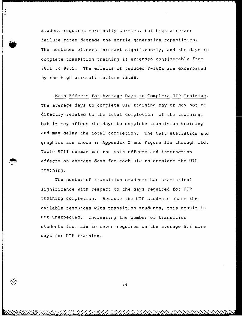
student requires more daily sorties, but high aircraft
failure rates degrade the sortie generation capabilties.
The combined effects interact significantly, and the days to
complete transition training is extended considerably from
78.1 to 90.5. The effects of reduced F-16Ds are excerbated
by the high aircraft failure rates.
Main Effects for Average Days to Complete UIP Training.
The average days to complete UIP training may or may not be
directly related to the total completion of the traininq,
but it may affect the days to complete transition training
and may delay the total completion. The test statistics and
graphics are shown in Appendix C and Figure lla through lld.
Table VIII summarizes the main effects and interaction
effects on average days for each UIP to complete the UIP
training.
The number of transition students has statistical
significance with respect to the days required for UIP
training completion. Because the UIP students share the
avilable resources with transition students, this result is
not unexpected. Increasing the number of transition
students from six to seven requires on the average 5.3 more
days for UIP training.
74
..-- 7 4

Table VIII
Effect for Day to Complete UIP Training
Factors/Interactions Effects for Each Level/ among Factors Combination
II III III IIII
Number of TransitionStudent pilots (a) 30.29 35.60
Number of F-16Cs (b) 32.26 33.63
Number of F-16Ds (c) 31.06 34.83
Aircraft FailureRates (d) 29.85 36.04
aXb 29.76 30.83 34.76 36.43
aXc 28.95 31.64 33.18 38.02
aXd 28.21 32.38 31.50 39.69
bXc 30.48 34.05 31.65 35.61
bXd 29.66 34.86 30.04 37.21
cXd 28.21 33.92 31.50 38.16
The F-16Ds and aircraft failure rates also have
significant effects. Five instead of six F-16Ds delays the
UIP training 3.8 days, and high aircraft failure rates
increase the days by 6.2.
Interaction Effects for Average Days to Complete UIP
Training. The significant interactions are the ones between
the transition student pilots and the F-16Ds, between the
transition students and aircraft failure rates, and between
the F-16Cs and aircraft failure rates. These interactions
75
l .A
40 40
35 35
30 30
25 25
20 20
I II I II
a. Number of Students b. Number or F-16Cs
40 40
35 35
30 30
25 25
20 20
"""I II I II
c. Number of F-16Ds d. ACFT Failure Rate
* I: Factor at baseline level
II: Facotr at expected level
Figure 11. Main Effects on Average Daysto Complete UIP Training
76
L .

40 40
Number 35 Number 35of of
F-16Cs 30 F-16Ds 30
25 25
20 20
I* II*I II
a. Number of Students b. Number of Students
40 40
ACFT Number .35)Failure ofRates 30 F-16Ds 30
25 25
20 20
I II III
C. Number of Students d. Number of F-16Cs
40 40
ACFT 35 ACFT 35Failure FailureRate 30 Rate 30
25 25
20 20
I 1I I II
e. Number of F-16Cs f. Number of F-16Ds
*I: Factor at baseline level II: Facotr at expected level
Figure 12. Interaction Effects on Average Daysto Complete UIP Training
77
are depicted in Figure 12a through 12f and Appendix D.
The first two interactions can be explained in the same
way as for the transition training case. More student
pilits require more sorties while the daily sortie
generation is decreased by the reduced number of F-l6Ds and
high aircraft failure rates.
The interaction of F-l6Cs and aircraft failure rates is
more difficult to explain because the number of F-l6Cs does
not have a significant effect on all response variables.
Sensitivity Analysis
Next the sensitivity of the levels of these factors
identified as important is examined. The purpose of this
analysis is to identify at which level or levels of these
factors the operation of the system is significantly
affected. A sensitivity analysis was conducted on each of
the factors selected. Each of the factors was tested in
isolation by holding other factor levels constant at the
baseline level defined in the experimental design. Four
replications of each run were performed. Again the one-way
analysis of variance (ANOVA) was used as the statistical
tool.
Sensitivity to Transition Student Pilots. The number
of transition student pilots was run for six and seven
students in each class. Tne ANOVA for the number of
78
P .

transition students appears in Appendix E-1. The tail
probability value (p-value) equals zero for the total
completion of the enti'-e training, which means that the
hypothesis or the equality of level means is rejected, and
significant differences exist in the number of days for each
student to complete the transition and the UIP training.
'he average number of days to complete the entire training
decreases considerably by 68.9, while the mean number of
days for the transition and UIP training increases.
Sensitivity to F-16Ds. The number of F-16Ds was run
for six and five after the first F-16Cs are delivered. This
means that after the second F-16Cs' arrival four or three
F-16Ds are used for the transition and the UIP training.
The results are statistical significance for all three
- - response variables. But the actual changes in response
variables do not appear very large in a practical sense.
The statistical outputs are shown in Appendix E-2.
Sensitivity to Aircraft Failure Rates. The aircraft
failure rate was run from low failure rates to nigh failure
rates, which doubles the low ones. The low and the high
values of aircraft failure rates and ground abort rates are
the same as the ones previously used in the experiment
(Table IV). The medium value is the average of these two
values. The total number of days to complete training is
not affected significantly, while the number of days to
complete the transition and the UIP training is. The days
79

required for the transition and thie UIP training increase
more rapidly i.e. 3.4 and 2.6 days, respectively, as the
failure rates are increased from the low rates to the medium
ones than from the medium rates to the high ones. The ANOSIA
results are shown in Appendix E-3.
Sensitivi-" to Mission Effectiveness. The mission
effectiveness rate is assumed equal to one minus the maximum
allowable additional sorties of four divided by the total
syllabus requirements times 100 (l-4/22)xlOO). The
additional sorties was run for 2, 4, and 6, which is
equivalent to 0.92, 0.83, and 0.73 for the mission
effectiveness rate, respectively. The ANOVA are represented
in Appendix E-4. The mission effectiveness rate is
significant for all response variables. The estimates of
means show the responses of the system increase more steeply
as the effectiveness rate varies from 0.92 to 0.83 than from
0.83 to 0.73.
Summary
The results of the experimental design were analyzed
using the analysis of variance techniques. The results of
the design of experiments were considered in order to find
the statistical significance of the factor levels and the
interactions among factors.
The days to complete entire training were not as
significant as other responses because of the preflight

groand training. Except for the F-16Cs, all factors chosen
for the experiment have significant effects on the number of
days for each student to complete the transition training
and the UIP training. The number of transition student
pilots appeared to be the most meaningful factor. One more
transition student pilot in each class delays the days
required for the transition and the UIP training. However,
with this additional student, the total number of student
training classes can be compressed from eight to seven.
The interactions among the transition student pilots,
the F-l6Ds, and the aircraft failure rates are significant
for the response variables.
Finally, a sensitivity analysis was conducted to find
how sensitive the model is to those factor levels identified
as significant.
81
VI. Conclusions and Recommendations
Conclusions
The F-16 implementation for the ROKAF is an extremely
important issue. The Peace Bridge Program Management Plan,
the Program Management Review, and the F-16 Implementation
Plan are the major sources for this study. These plans
address the procedures and factors planned for implementing
the F-l6 for the ROKAF. However, no systematic and formal
detailed analysis of F-16 pilot training existed to identify
the significant factors or to estimate the magnitude of the
change in the system responses from a change in factor
levels.
To provide the necessary analysis, a conceptualization
of the F-16 flight training system was accomplished, and the
key components and variables were identified. With this
information, a SLAM simulation model of the F-16 training
system, including the transition course and the upgrading
instructor pilot course, was developed. Verification and
validation were accomplished, and statistical results were
obtained from the model.
Several variables, likely to affect the system were
selected as factors for experimental design. The system
reponse was estimated by measuring the number of days to
complete the entire training, the number of days for eachl
82
p., j( 7 W .
transition student pilot to complete transition training,
and the number of days for each upgrading instructor pilot
to complete the upgrading instructor pilot training. A
complete factorial design was used for the experiment in
order to identify the main effects for each factor and the
interactions among factors.
The results show that the number of the transition
students in each class has the most significant effects on
the days to complete the entire training. one more
transition student in each class can compress the total
transition training class from eight to seven. The total
required days were not significantly affected by the factor
levels of the number of F-l6Cs, the number of F-l6Ds, and
aircraft failure rates because of the slack provided by
preflight ground academic training days. In addition,
statistically significant two-way interaction affecting the
days to complete the training existed between the number of
transition student pilots and the aircraft failure rates.
As an additional measure of system response, the days
for each transition student to complete the transition were
investigated because the days to complete the entire
training is highly dependent on this measure. rhe number of
transition students, the number of P-l6Ds, and the aircraft
failure rates have statistically significant effects on the
days to complete the transition training. One more
transition student in each class adds ten days for each
* ~63

student's completion time. But as mentioned earlier, the
entire training can be compressed by 61 days. The
interaction among the factors, the transition students, the
number of F-16Ds, and the aircraft failure rates have
statistical significance.
Another additional measure of the system response is
the number of the days for each upgrading instructor pilot
to complete the training. The number of transition student
pilots, the number of F-16Ds, and the aircraft failure rates
appeared as statistically significant factors. These
factors affect the number of the days required for upgrading
instructor training, as well as the number of the days to
complete the transition training and entire training. Also,
interactions among the number of the transition student
pilots, the number of F-16Ds, and aircraft failure rates
exist.
The experiment shows that a number of factor
interactions also affect the F-16 implementation for the
ROKAF. Due to these interactions and general complexity of
the system, the specific results of the experiment could not
be accurately predicted. But the trends were shown.
Therefore, the model provides a powerful tool for analyzing
the effects of potential changes to the plan. The model
also gave valuable insight into the beha.rior of the system
during the initial transitioning phase. Finally the model
car cover other scenarios by changing values of input
variables.
b4
', -_ .-.. -_. -.. ... -, ... .. . . . . . ..
rIe .A L Ud LLJLIS
Not all aspects of the system could be analyzed due to
the scope of the study. Further study of other areas can
provide additional insight and information to the ROKAF.
Some of these areas are presented below.
This model incooperates several key assumptions. Some
may need to be altered as the training proceeds.
I. The maintenance support ability of the ROKAF and
the data for F-16C/D is assumed to be similar to that of the
USAF and that for the F-16A/B.
2. The possible alternative mission types are limited
to the substitution of F-16Cs for F-16Ds.
3. The flying time is assumed as the average assigned
mission flight time.
4. A student pilot is assumed to fly a sortie a day.
5. It is assumed the simulator is not used for this
training. The syllabus requirements of the flying sortie
may be increased instead of the simulator training.
More sensitivity analysis can be performed on all these
assumptions to determine the impact on the system responses.
The simulation model can be used for showing the effects
from a change of these assumptions.
d 5
* '.- b

Hibliograpty
I. BanKs, Jerry and Carson II, John S. Discrete-Event
S'stem Simulation. Englewood Cliffs: Prentice-Hall, Inc.,1984.
2. Dickinson, Major Jack R. Jr. and Moses, Captain Glenn E.
An Analysis of the Implementation Plan for the ConversionTrom the T-37 to the T-46 Aircraft in Undergraduate Pilot
Training. MS, AFIT/GST/OS/84M-8. School of Engineering,Air Force Institute of Technology (AU) , Wright-Palterson AFBOH, March 1984.
3. Dixon, W. J., et al. BMDP Statistical Software. Los
Angeles: University of California Press, 1984.
4. Green, Paul E. Analyzing Multi-variate Data. Illinois:
Dryden Press, 1978.
5. Jensen, Seth V. An Analysis of the Pilot ConversionProcess for the Air Force T-46 Jet Trainer Aircraft. MS,
Thesis, LSSR 51-83. School of System and Logistics, AirForce Institute of Technology (AU) , Wright-Patterson AFB OH,
September 1983.
6. Montgomery, Douglas C. Design and Analysis of
Experiments. Second Edition. New YorK: John Wiley & Sons,1984.
7. Niemeyer, Captain Joseph B. and Selva, Captain MichaelD. An Analysis of the Specialized Undergraduate PilotTraining (SUPT) Program. MS, AFIT/GST/OS/85M-9, School ofEngineering, Air Force Institute of Technology (AU), Wright-Patterson AFB, March 1985.
8. ------- Peace Bridge Program Management Plan, HQ AFLC
ILC/OOWK, WPAFB, 15 April 1985.
9. -------. Peace Bridge Program Management Review 4 Minutes,ASD/YPXI, WPAFB, October 1984.
10. Pritsker, A. Alan B. introduction to Simulation andSLAM II. New York: Halsted Press, 1984.
Development Project. San Diego: Courseware, Inc.,California, March 1981.
12. The F-16 ImplementatLon Plan. HQ./ROIKAF, March1985.
13. Telephone Interview. 23 July 1985.
J,>-. k ". ,".. ' , 'W-l"-.-.' -%" , .". J
% J . _ . . . ."""""" ,.-.-' "

AD-A172 S28 AN ANALSIS O PILOT TRAINING FO F-is IPLEENTATIO 2/2BY THE REPUBLIC OF .(U) AIR FORCE INST OF TECHHRIGHT-PATTERSON RFB OH SCHOOL OF ENGI V J LEE
UNCLASSIFIED NOV 85 AFIT/GOR/OS/35D-i2 F/G 5/9
llllllIomol
Ehhhhhh

~~%%
1.0i M28 ~liB~ L: u 2 2
1.25 1111. 111.
MICROCOPY RESOLUTION TEST CHART '
NATIONAL BUREAU Of STANO)AROS 19b3-A
*C~~£1h 4.
*z %
v* !

14. Wood, Captain John P. A Model to Evaluate F-4E
Squadron Scheduled Sortie Rates and Pilot Graduated CombatCapability Status. MS Thesis, AFlT/GST/OS/82M-16. Schoolof Engineering, Air Force Institute of Technology (AU),Wright-Patterson AFB OH, March 1984.
87

Appendix A. Data for Design of Experiment
1 554.5 68.1 26.5 1 1 1 1 33 487.5 75.5 30.1 2 1 1 12 554.4 69.7 25.7 1 1 1 1 34 485.2 76.6 30.9 2 1 1 13 552.2 68.9 27.0 1 1 1 1 35 485.7 73.2 28.5 2 1 1 14 556.2 70.7 27.0 1 1 1 1 36 483.4 73.8 28.0 2 1 1 1
5 561.4 75.9 29.0 1 1 1 2 37 502.4 88.5 35.2 2 1 1 26 556.2 73.7 29.3 1 1 1 2 38 501.8 87.6 37.5 2 1 1 27 559.4 75.6 31.2 11 12 39 503.2 87.3 39.12 11 28 552.4 71.9 27.6 1 1 1 2 40 501.5 83.2 35.0 2 1 1 2
9 558.6 73.2 29.1 1 1 2 1 41 490.2 83'8 34.1 2 1 2 110 556.6 72.3 31.3 1 1 2 1 42 488.4 78.2 33.6 2 1 2 111 557.6 72.2 28.7 1 1 2 1 43 489.4 81.3 31.4 2 1 2 112 561.2 71.7 28.9 1 1 2 1 44 494.2 82.2 33.8 2 1 2 1
13 564.5 79.5 32.3 1 1 2 2 45 507.8 93.9 38.7 2 1 2 214 562.6 81.1 33.1 1 1 2 2 46 509.2 94.3 40.0 2 1 2 215 564.6 81.4 34.8 1 1 2 2 47 508.6 93.4 40.8 2 1 2 216 568.4 83.2 34.7 1 1 2 2 48 507.4 92.8 39.5 2 1 2 2
17 554.4 69.9 27.3 1 2 1 1 49 486.5 72.5 29.7 2 2 1 118 554.4 67.6 28.4 1 2 1 1 50 485.2 73.8 27.8 2 2 1 119 549.6 70.1 27.5 1 2 1 1 51 484.2 72.0 31.9 2 2 1 120 556.2 68.9 26.4 1 2 1 1 52 487.6 71.4 28.6 2 2 1 1
lit&21 555.4 73.4 32.7 1 2 1 2 53 501.4 87.2 38.4 2 2 1 222 553.5 74.8 33.9 1 2 1 2 54 499.5 85.3 37.8 2 2 1 223 552.2 72.6 31.6 1 2 1 2 55 498.7 84.8 36.2 2 2 1 224 554.8 73.2 32.1 1 2 1 2 56 500.8 86.7 36.1 2 2 1 2
25 556.6 72.2 30.8 1 2 2 1 57 493.6 83.5 34.1 2 2 2 126 559.6 75.6 28.5 1 2 2 1 58 488.1 82.4 33.8 2 2 2 127 555.5 73.5 29.4 1 2 2 1 59 488.5 84.4 35.3 2 2 2 128 557.6 73.9 28.8 1 2 2 1 60 496.6 84.9 32.4 2 2 2 1
29 561.4 80.4 34.8 1 2 2 2 61 510.1 96.2 48.5 2 2 2 230 565.4 83.5 32.4 1 2 2 2 62 508.9 94.8 44.5 2 2 2 231 563.5 81.3 33.7 1 2 2 2 63 509.5 95.3 42.3 2 2 2 232 564.3 81.0 34.9 1 2 2 2 64 508.8 95.8 45.5 2 2 2 2
Coulumn 1: identification number2: days to complete entire training3: days for each student to complete transition4: days for each student to complete UIP course5: factor level for the number of transition SP6: factor level for the number of F-l6Ds7: factor level for the number of F-l6Cs8: factoc level for aircraft failure rates
Each row data represents one replication of the model.
88

Appendix B. Data for Sensitivity Analysis
*Number of Transition Student Number fo F-l6Ds
1 554.5 68.1 26.5 1* 1 554.5 68.1 26.5 12 554.5 69.7 25.7 1 2 554.5 69.7 25.7 13 552.2 68.9 27.0 1 3 552.2 68.9 27.0 14 556.2 70.7 27.0 1 4 556.2 70.7 27.0 1
5 487.5 75.5 30.1 2* 5 558.6 73.2 29.1 2*6 485.2 76.6 30.9 2 6 556.6 72.3 31.3 27 485.7 73.2 28.5 2 7 557.6 72.2 28.7 28 483.4 73.8 28.0 2 8 561.2 71.7 28.9 2
*1: 6 Students *1: 6 F-l6Ds2: 7 Students 2: 5 F-l6Ds
Aircraft Failure Rate Mission Effectiveness Rate
1 554.5 68.1 26.5 1* 1 553.2 67.6 27.6 12 554.4 69.7 25.7 1 2 552.2 67.1 27.3 13 552.2 68.9 27.0 1 3 551.2 66.3 26.9 14 556.2 70.7 27.0 1 4 549.5 66.2 25.9 1
557.4 74.6 28.4 25 554.5 68.1 26.5 26 556.5 73.1 29.0 2 6 554.4 69.7 25.7 27 551.6 71.6 30.2 2 7 552.2 68.9 27.0 28 558.6 71.6 28.9 2 8 556.2 70.7 27.0 2
9 561.4 75.9 29.0 3* 9 557.6 77.0 34.3 310 556.2 73.7 29.3 3 10 555.2 76.0 32.3 311 559.4 75.6 31.2 3 11 561.6 77.0 33.8 312 552.4 71.9 27.6 3 12 559.8 78.1 33.5 3
*1 2 3 *1: High (0.92)Preflight 0.025 0.038 0.5 2: Medium (0.83)Ground 3: Low (0.73)Abort 0.06 0.1 0.13Postflight 0.033 0.05 0.067
88

Appendix C. Statistical Results for ANOVA
C-I. MAIN EFFECT OF TRANSITION STUDENT PILOT
ESTIMATES OF MEANS
NOSP6 NOSP7 TOTAL1 2 3
TOTCOM 2 557.9749 496.6844 527.3297TXCOM 3 74.4063 84.2688 79.3375UIPCOM 4 30.2937 35.5969 32.9453
ONE WAY ANALYSIS OF VARIANCE FOR VARIABLE TOTCOM
ANALYSIS OF VARIANCE TABLE
SOURCE OF VAR D.F SUM OF SQ MEAN SQ F-VALUE P-VALUEEQ OF CELL MEANS 1 60104.520 60104.5 123.716 .0000
ERROR 62 3316.213 53.49
ONE WAY ANALYSIS OF VARIANCE FOR VARIABLE TXCOM******** *********** ****** **** ****** ****** ******* **
ANALYSIS OF VARIANCE TABLE
SOURCE OF VAR D.F SUM OF SQ MEAN SQ F-VALUE P-VALUEEQ OF CELL MEANS 1 1556.3035 1556.30 37.5569 .0000
ERROR 62 2569.1875 41.4385
ONE WAY ANALYSIS OF VARIANCE FOR VARIABLE UIPCOM
ANALYSIS OF VARIANCE TABLE
SOURCE OF VAR D.F SUM OF SQ MEAN SQ F-VALUE P-VALUEEQ OF CELL MEANS 1 449.9696 449.9696 25.3382 .0000
ERROR 62 1101.0286 17.7585
90
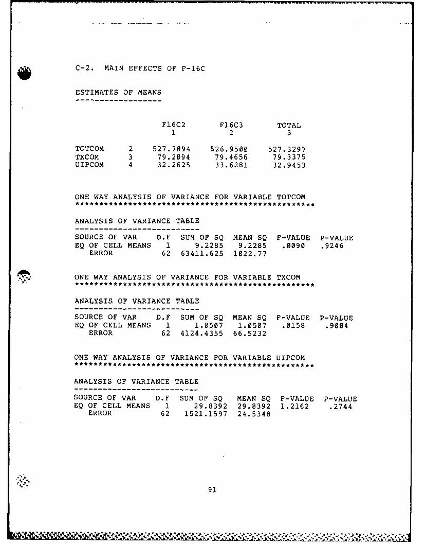
C-2. MAIN EFFECTS OF F-16C
ESTIMATES OF MEANS
F16C2 F16C3 TOTAL1 2 3
TOTCOM 2 527.7094 526.9500 527.3297TXCOM 3 79.2094 79.4656 79.3375UIPCOM 4 32.2625 33.6281 32.9453
ONE WAY ANALYSIS OF VARIANCE FOR VARIABLE TOTCOM******************************* *******************
ANALYSIS OF VARIANCE TABLE
SOURCE OF VAR D.F SUM OF SQ MEAN SQ F-VALUE P-VALUEEQ OF CELL MEANS 1 9.2285 9.2285 .0090 .9246
ERROR 62 63411.625 1022.77
ONE WAY ANALYSIS OF VARIANCE FOR VARIABLE TXCOM
ANALYSIS OF VARIANCE TABLE
SOURCE OF VAR D.F SUM OF SQ MEAN SQ F-VALUE P-VALUEEQ OF CELL MEANS 1 1.0507 1.0507 .0158 .9004
ERROR 62 4124.4355 66.5232
ONE WAY ANALYSIS OF VARIANCE FOR VARIABLE UIPCOM
ANALYSIS OF VARIANCE TABLE------- ------------SOURCE OF VAR D.F SUM OF SQ MEAN SQ F-VALUE P-VALUEEQ OF CELL MEANS 1 29.8392 29.8392 1.2162 .2744
ERROR 62 1521.1597 24.5348
91

C-3. MAIN EFFECTS OF F-16D
ESTIMATES OF MEANS
F16D6 F16D5 TOTAL1 2 3
TOTCOM 2 524.1188 530.5406 527.3297TXCOM 3 75.7625 82.9125 79.3375UIPCOM 4 31.0625 34.8281 32.9453
ONE WAY ANALYSIS OF VARIANCE FOR VARIABLE TOTCOM
ANALYSIS OF VARIANCE TABLE
SOURCE OF VAR D.F SUM OF SQ MEAN SQ F-VALUE P-VALUEEQ OF CELL MEANS 1 659.8477 659.848 .6518 .4225
ERROR 62 62761.12 1012.28
ONE WAY ANALYSIS OF VARIANCE FOR VARIABLE TXCOM
ANALYSIS OF VARIANCE TABLE
SOURCE OF VAR D.F SUM OF SQ MEAN SQ F-VALUE P-VALUEEQ OF CELL MEANS 1 817.9604 817.9604 15.3328 .0002
ERROR 62 3307.5308 53.3473
ONE WAY ANALYSIS OF VARIANCE FOR VARIABLE UIPCOM
ANALYSIS OF VARIANCE TABLE
SOURCE OF VAR D.F SUM OF SQ MEAN SQ F-VALUE P-VALUEEQ OF CELL MEANS 1 226.8780 226.878 10.6232 .0018
ERROR 62 1324.1202 21.3568
92

C-4. MAIN EFFECTS OF AIRCRAFT FAILURE RATE
ESTIMATES OF MEANS
LOFR HIFR TOTAL1 2 3
TOTCOM 2 522.1719 532.4875 527.3297TXCOM 3 74.6250 84.0500 79.3375UIPCOM 4 29.8531 36.0375 32.9453
ONE WAY ANALYSIS OF VARIANCE FOR VARIABLE TOTCOM******************************************** ******
ANALYSIS OF VARIANCE TABLE
SOURCE OF VAR D.F SUM OF SQ MEAN SQ F-VALUE P-VALUEEQ OF CELL MEANS 1 1702.6100 1702.61 1.7104 .1958
ERROR 62 61718.277 995.456
ONE WAY ANALYSIS OF VARIANCE FOR VARIABLE TXCOM
ANALYSIS OF VARIANCE TABLE
SOURCE OF VAR D.F SUM OF SQ MEAN SQ F-VALUE P-VALUEEQ OF CELL MEANS 1 1421.2864 1421.286 32.5863 .0000
ERROR 62 2704.1987 43.6161
ONE WAY ANALYSIS OF VARIANCE FOR VARIABLE UIPCOM
ANALYSIS OF VARIANCE TABLE-----------------------------------SOURCE OF VAR D.F SUM OF SQ MEAN SQ F-VALUE P-VALUEEQ OF CELL MEANS 1 611.9446 611.945 40.4029 .0000
ERROR 62 939.0545 15.1460
93

Appendix D. Statistical Results for MANOVA
D-1. SUMMARY STATISTICS FOR VARIATE(S):
VARIATE COUNT MEAN STDERROR STDDEV MAXIMUM MINIMUM
TOTCOM 64 527.3 3.966 31.73 568.4 483.4TXCOM 64 79.34 1.012 8.092 96.20 67.60UIPCOM 64 32.95 .6202 4.962 48.50 25.70
D-2. MARGINAL STATISTICS
FACTOR LEVEL VARIATE MEAN STDERR STDDEV MAX MIN
NOSP NOSP6 TOTCOM 558.0 .8131 4.600 568.4 549.6TXCOM 74.41 .8217 4.648 83.50 67.60
UIPCOM 30.29 .5018 2.839 34.90 25.70NOSP7 TOTCOM 496.7 1.638 9.264 510.1 483.4
TXCOM 84.27 1.384 7.827 96.20 71.40UIPCOM 35.60 .9263 5.240 48.50 27.80
F16C F16C2 TOTCOM 527.7 5.733 32.43 568.4 483.4TXCOM 79.21 1.385 7.835 94.30 68.10
UIPCOM 32.26 .7686 4.348 40.80 25.70F16C3 TOTCOM 527.0 5.573 31.52 568.4 488.1
TXCOM 79.47 1.496 8.465 96.20 67.60UIPCOM 33.63 .9709 5.492 48.50 26.40
F16D F16D6 TOTCOM 524.1 5.616 31.77 561.4 483.4TXCOM 75.76 1.172 6.632 88.50 67.60
UIPCOM 31.06 .7068 3.998 39.10 25.70F16D5 TOTCOM 530.5 5.633 31.87 568.4 488.1
TXCOM 82.91 1.400 7.919 96.20 71.70UIPCOM 34.83 .9139 5.170 48.50 28.50
ACFR LOFR TOTCOM 522.2 6.094 34.47 561.2 483.4TXCOM 74.62 .9200 5.204 84.90 67.60
UIPCOM 29.85 .4667 2.640 35.30 25.70HIFR TOTCOM 532.5 5.008 28.33 568.4 498.7
TXCOM 84.05 1.371 7.756 96.20 71.90UIPCOM 36.04 .8537 4.829 46.50 27.60
..S* 94
'S
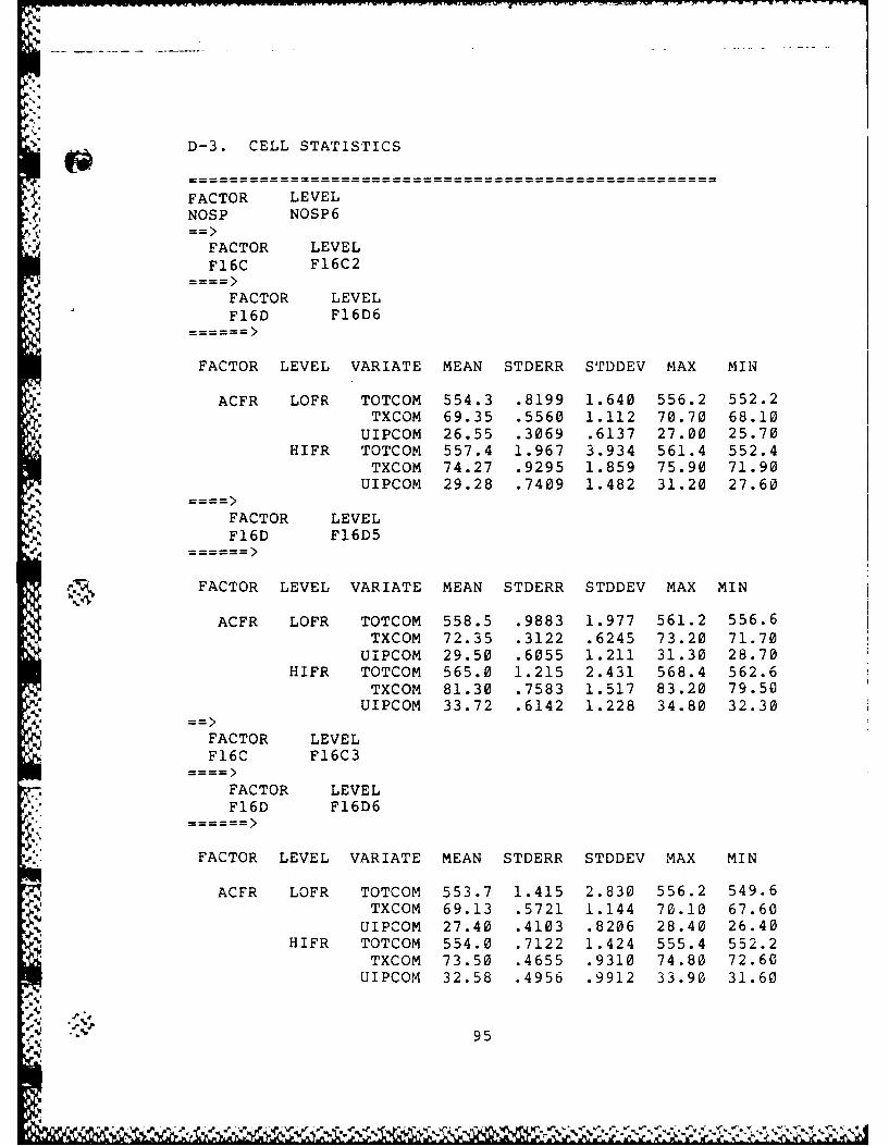
D-3. CELL STATISTICS
FACTOR LEVELNOSP NOSP6
FACTOR LEVELF16C F16C2
FACTOR LEVELF16D F16D6
FACTOR LEVEL VARIATE MEAN STDERR STDDEV MAX MIN
ACFR LOFR TOTCOM 554.3 .8199 1.640 556.2 552.2* TXCOM 69.35 .5560 1.112 70.70 68.10
UIPCOM 26.55 .3069 .6137 27.00 25.70HIFR TOTCOM 557.4 1.967 3.934 561.4 552.4
TXCOM 74.27 .9295 1.859 75.90 71.90UIPCOM 29.28 .7409 1.482 31.20 27.60
FACTOR LEVELF16D F16D5
FACTOR LEVEL VARIATE MEAN STDERR STDDEV MAX MIN
ACFR LOFR TOTCOM 558.5 .9883 1.977 561.2 556.6TXCOM 72.35 .3122 .6245 73.20 71.70
UIPCOM 29.50 .6055 1.211 31.30 28.70HIFR TOTCOM 565.0 1.215 2.431 568.4 562.6
TXCOM 81.30 .7583 1.517 83.20 79.50UIPCOM 33.72 .6142 1.228 34.80 32.30
FACTOR LEVELF16C F16C3
* FACTOR LEVELF16D F16D6
k.== == ==
FACTOR LEVEL VARIATE MEAN STDERR STDDEV MAX MIN
ACFR LOFR TOTCOM 553.7 1.415 2.830 556.2 549.6TXCOM 69.13 .5721 1.144 70.10 67.60
UIPCOM 27.40 .4103 .8206 28.40 26.40HIFR TOTCOM 554.0 .7122 1.424 555.4 552.2
TXCOM 73.50 .4655 .9310 74.80 72.60UIPCOM 32.58 .4956 .9912 33.90 31.60
'Z . %' 95
... ..

FACTOR LEVELFl6D Fl6D5
FACTOR LEVEL VARIATE MEAN STDERR STDDEV MAX MIN
ACFR LOFR TOTCOM 557.3 .8712 1.742 559.6 555.5TXCOM 73.80 .7012 1.402 75.60 72.20
UIPCOM 29.37 .5105 1.021 30.80 28.50HIFR TOTCOM 563.7 .8451 1.690 565.4 561.4
TXCOM 81.55 .6764 1.353 83.50 80.40UIPCOM 33.95 .5838 1.168 34.90 32.40
FACTOR LEVELNOSP NOSP7
FACTOR LEVELF16C F16C2
FACTOR LEVEL
F16D F16D6
FACTOR LEVEL VARIATE MEAN STDERR STDDEV MAX MIN
' ACFR LOFR TOTCOM 485.5 .8431 1.686 487.5 483.4TXCOM 74.77 .7793 1.559 76.60 73.20
UIPCOM 29.38 .6775 1.355 30.90 28.00HIFR TOTCOM 502.2 .3750 .7500 503.2 501.5
TXCOM 86.65 1.178 2.356 88.50 83.20UIPCOM 36.70 .9806 1.961 39.10 35.00
FACTOR LEVEL
F16D F16D5
FACTOR LEVEL VARIATE MEAN STDERR STDDEV MAX MIN
ACFR LOFR TOTCOM 490.6 1.271 2.542 494.2 488.4TXCOM 81.38 1.178 2.356 83.80 78.20
UIPCOM 33.22 .6169 1.234 34.10 31.40HIFR TOTCOM 508.3 .4031 .8062 509.2 507.4
TXCOM 93.60 .3240 .6481 94.30 92.80UIPCOM 39.75 .4406 .8813 40.80 38.70
96
. .
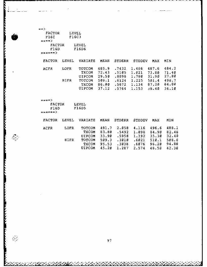
FACTOR LEVEL
F16C F16C3
FACTOR LEVEL
F16D F16D6
FACTOR LEVEL VARIATE MEAN STDERR STDDEV MAX MIN
ACFR LOFR TOTCOM 485.9 .7432 1.486 487.6 484.2TXCOM 72.43 .5105 1.021 73.80 71.40
UIPCOM 29.50 .8898 1.780 31.90 27.80HIFR TOTCOM 500.1 .6124 1.225 501.4 498.7
TXCOM 86.00 .5672 1.134 87.20 84.80
UIPCOM 37.12 .5764 1.153 j8.40 36.10
FACTOR LEVEL
F16D F16D5
FACTOR LEVEL VARIATE MEAN STDERR STDDEV MAX MIN
ACFR LOFR TOTCOM 491.7 2.058 4.116 496.6 488.1TXCOM 83.80 .5492 1.098 84.90 82.40
UIPCOM 33.90 .5958 1.192 35.30 32.40HIFR TOTCOM 509.3 .3010 .6021 510.1 508.8
TXCOM 95.53 .3038 .6076 96.20 94.80
UIPCOM 45.20 1.287 2.574 48.50 42.30
97

D-4. DESIGN TYPES OF FACTORIAL ANALYSIS
DESIGN TYPE IS BETWEEN, CONTRAST. MODEL.CODE IS CONST. NAME IS 'OVALL: GRAND MEAN'.,
DESIGN FACTOR IS NOSP.CODE IS EFFECT. NAME IS 'N: NOSP'./
DESIGN FACTOR IS F16C.CODE IS EFFECT. NAME IS 'F: F16C'./
DESIGN FACTOR IS F16D.CODE IS EFFECT. NAME IS 'B: F16D'./
DESIGN FACTOR IS ACFR.CODE IS EFFECT. NAME IS 'A: ACFR'./
INTERACT EFFECTS ARE N,F.
NAME IS NF./
INTERACT EFFECTS ARE N,B.NAME IS NB./
INTERACT EFFECTS ARE N,A.
NAME IS NA./
INTERACT EFFECTS ARE F,B.
NAME IS FB./
INTERACT EFFECTS ARE F,A.NAME IS FA./
INTERACT EFFECTS ARE B,A.NAME IS BA./
INTERACT EFFECTS ARE NF,B.NAME IS NFB./
INTERACT EFFECTS ARE NF,A.NAME IS NFA./
INTERACT EFFECTS ARE NB,A.NAME IS NBA./
- INTERACT EFFECTS ARE FB,A.NAME IS FBA./
INTERACT EFFECTS ARE NFB,A.
NAME IS NFBA./
"
"< 98
. ....................-. . -- ....

D-5. ESTIMATES FOR BETWEEN-GROUPS DESIGN
PARAMETERS (PHI). ROWS: PARAMETERS; COLUMNS: VARIABLES(WITHIN-DESIGN CELLS).
EFFEC: OVALL: GRAND MEAN1 2 3
527.32969 79.337500 32.945312
EFFECT: N: NOSP1 2 3
30.645313 -4.9312506 -2.6515624
EFFECT: F: F16C1 2 3
.37968779 -.12812543 -.68281257
EFFECT: B: F16D1 2 3
-3.2109323 -3.5750003 -1.8828124
EFFECT: A: ACFR1 2 3
-5.1578135 -4.7125003 -3.0921876
.- EFFECT: NF1 2 3
.44531298 .40624857e-01 .15156251
EFFECT: NB1 2 3
.60942173e-01 .73125029 .53906244
EFFECT: NA1 2 3
3.1328082 1.4624999 1.0046875
EFFECT: FB1 2 3
.33906412 .62812495 .95312595e-01
EFFECT: FA1 2 3
-.34531260 -.34375191e-01 .49218762
EFFECT: BA1 2 3
.86406469 .36875033 .23593760
* 99
*~d s.' V 'o

EFFECT: NFB
1 2 3-. 15156031 -. 29062486 -. 60156244
EFFECT: NFA1 2 3
-. 17186642e-01 -. 18437481 -. 14218730
EFFECT: NBA1 2 3
.32343912 .55624986 -. 12343758
EFFECT: FBA
1 2 3
-. 31093931 .17812490 -. 14843750
EFFECT: NFBA1 2 3
-. 15645027e-02 -. 96875191e-01 .41093737
* .,.s.,100
'4

D-6. TEST STATISTICS
EFFECT VARIATE STATISTIC F DF P
OVALL: GRAND MEANz . -ALL----
S= 1,T= 3,DFH= 1,DFE= 48HT EVALS= .99998817HE EVALS= 84525.073TSQ= *.405720e+07 3, 46 .0000
*ABOVE STATISTIC POSSIBLY ACCURATE TO ONLY 4 DIGITS.NUMERICALLY CONSERVATIVTE F: ***** 3, 46 .0000
TOTCOMSS= .177969e+08MS5 .177969e+08 *****1, 48 .0000
TXCOMSS= 402844.MS= 402844. 1, 48 .0000
U IPCOMSS= 69465.2MS= 69465.2 36883.16 1, 48 .0000
N: NOSP* -ALL----
S= 1,T= 3,DFH= 1,DFE= 48HT EVALS= .99766360HE EVALS= 427.00884TSQ= 20496.4 6547.47 3, 46 .0000
TOTCOMSS= 60104.7
TCMMS= 60104.7 746.78 1, 48 .0000
SS= 1556.30MS= 1556.30 797.89 1, 48 .0000
UIPCOMSS= 449.970MS= 449.970 238.92 1, 48 .0000b
F: F16C* -ALL----
S= 1,T= 3,DFH= 1,DFE= 48HT EVALS= .27779769HE EVALS= .38465355TSQ= 18.4634 5.90 3, 46 .0017
TOTCOMSS= 9.22642MS= 9.22642 1.96 1, 48 .1683
TXCOMSS= 1.05063MS= 1.05063 .54 1, 48 .4666
UIPCOM
101
~~~~~~~~~~ n, ̂ 'n2 JU.~~. ~ -. * ~

SS= 29.8389
MS= 29.8389 15.84 1, 48 .0002B: F16DO -ALL-..-
S= 1,T= 3,DFH= 1,DFE= 48
HT EVALS= .90921037HE EVALS= 10.014473TSQ= 480.695 153.56 3, 46 .0000
TOTCOMSS= 659.846MS= 659.846 139.94 1, 48 .0000
TXCOMSS= 817.960MS= 817.960 419.35 1, 48 .0000
UIPCOMSS= 226.879MS= 226.879 120.46 1, 48 .0000
A: ACFR-ALL----
S= 1,T= 3,DFH= 1,DFE= 48HT EVALS= .95289417HE EVALS= 20.228796TSQ= 970.982 310.17 3, 46 .0000
,, TOTCOM
SS= 1702.59MS= 1702.59 361.08 1, 48 .0000
TXCOMSS= 1421.29
UIPCOMMS= 1421.29 728.67 1, 48 .0000i ' UIPCOM
SS= 611.944MS= 611.944 324.92 1, 48 .0000
NF-ALL----
S= 1,T= 3,DFH= 1,DFE= 48HT EVALS= .07692595HE EVALS= .83336709e-01TSQ= 4.00016 1.28 3, 46 .2931
TOTCOMSS= 12.6914MS= 12.6914 2.69 1, 48 .1074
TXCOMSS= .105624MS= .105624 .05 1, 48 .8170
UIPCOMSS= 1.47016
MS= 1.47016 .78 1, 48 .3814NB
-ALL----S= 1,T= 3,DFH= 1,DFE= 48HT EVALS= .34940890HE EVALS= .53706375
"- 102
W.r re r ,.
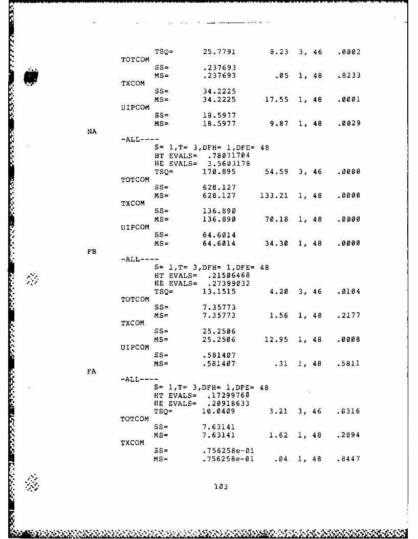
TSQ= 25.7791 8.23 3, 46 .0002TOTCOM
SS= .237693MS= .237693 .05 1, 48 .8233
TXCOM
* SS= 34.2225MS= 34.2225 17.55 1, 48 .0001
UIPCOMSS= 18.5977MS= 18.5977 9.87 1, 48 .0029
NA-ALL----
S= 1,T= 3,DFH= 1,DFE= 48HT EVALS= .78071704HE EVALS= 3.5603178TSQ= 170.895 54.59 3, 46 .0000
TOTCOMSS= 628.127MS= 628.127 133.21 1, 48 .0000
TXCOMSS= 136.890MS= 136.890 70.18 1, 48 .0000
UIPCOMSS= 64.6014MS= 64.6014 34.30 1, 48 .0000
FB-ALL----
S= 1,T= 3,DFH= 1,DFE= 48.. HT EVALS= .21506468
HE EVALS= .27399032TSQ= 13.1515 4.20 3, 46 .0104
TOTCOMSS= 7.35773MS= 7.35773 1.56 1, 48 .2177
TXCOMSS= 25.2506
MS= 25.2506 12.95 1, 48 .0008UIPCOM
SS= .581407MS= .581407 .31 1, 48 .5811
FA-ALL----
S= 1,T= 3,DFH= 1,DFE= 48HT EVALS= .17299760HE EVALS= .20918633TSQ= 10.0409 3.21 3, 46 .0316
TOTCOMSS= 7.63141MS= 7.63141 1.62 1, 48 .2094
TXCOMSS= .756258e-01MS= .756258e-01 .04 1, 48 .8447
S103
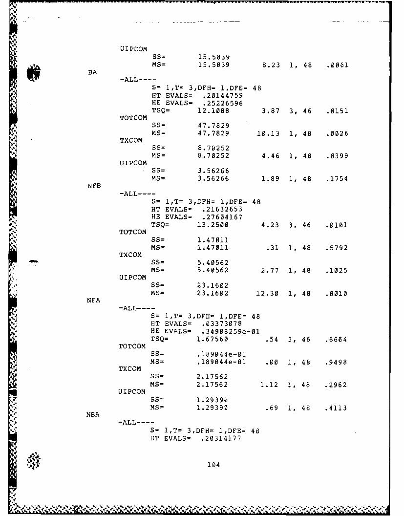
__~ ~ ~~~~~~~~~~~ - - - -. . -... - - - - -- - - -- - - -... "
UICMSS= 15.5039MS= 15.5039 8.23 1, 48 .0061
BA
S= 1,T= 3,DFH= 1,DFE= 48HT EVALS= .20144759HE EVALS= .25226596TSQ= 12.1088 3.87 3, 46 .0151
TOTCOMSS= 47.7829MS= 47.7829 10.13 1, 48 .0026
TXCOMSS= 8.70252MS= 8.70252 4.46 1, 48 .0399
UIPCOMSS= 3.56266MS= 3.56266 1.89 1, 48 .1754
NFB-ALL----
S= 1,T= 3,DFH= 1,DFE= 48HT EVALS= .21632653HE EVALS= .27604167TSQ= 13.2500 4.23 3, 46 .0101
TOTCOMSS= 1.47011MS= 1.47011 .31 1, 48 .5792
TXCOMSS= 5.40562MS= 5.40562 2.77 1, 48 .1025
UIPCOMSS= 23.1602
MS= 23.1602 12.30 1, 48 .0010NFA
-ALL----S= 1,T= 3,DFH= 1,DFE= 48HT EVALS= .03373078HE EVALS= .34908259e-01TSQ= 1.67560 .54 3, 46 .6604
TOTCOMSS= .189044e-01MS= .189044e-01 .00 1, 48 .9498
TXCOMSS= 2.17562MS= 2.17562 1.12 1, 48 .2962
UIPCOMSS= 1.29390MS= 1.29390 .69 1, 48 .4113
NBA-ALL----
S= 1,T= 3,DFH= 1,DFE= 48HT EVALS= .20314177
104

HE EVALS= .25492837
TSQ= 12.2366 3.91 3, 46 .0144TOTCOM
SS= 6.69522MS= 6.69522 1.42 1, 48 .2393
TXCOMSS= 19.8025
MS= 19.8025 10.15 1, 48 .0025UIPCOM
SS= .975158
MS= .975158 .52 1, 48 .4753FBA
-ALL----S= 1,T= 3,DFH= 1,DFE= 48
HT EVALS= .10776842HE EVALS= .12078526TSQ = 5.79769 1.85 3, 46 .1510
TOTCOMSS= 6.18773MS= 6.18773 1.31 1, 48 .2577
TXCOMSS= 2.03062MS= 2.03062 1.04 1, 48 .3127
UIPCOMSS= 1.41016MS= 1.41016 .75 1, 48 .3912
NFBA-ALL----
S= 1,T= 3,DFH= 1,DFE= 48HT EVALS= .12883351HE EVALS= .14788621
TSQ= 7.09854 2.27 3, 46 .0932TOTCOM
SS= .156651e-03MS= .156651e-03 .00 1, 48 .9954
TXCOMSS= .600627MS= .600627 .31 1, 48 .5815
UIPCOMSS= 10.8076MS= 10.8076 5.74 1, 48 .0205
ERRORTOTCOM
SS= 226.33343MS= 4.7152797
TXCOMSS= 93.625016MS= 1.9505212
UIPCOMSS= 90.402486MS= 1.8833851
105
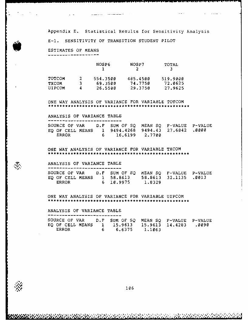
Appendix E. Statistical Results for Sensitivity Analysis
E-l. SENSITIVITY OF TRANSITION STUDENT PILOT
ESTIMATES OF MEANS
NOSP6 NOSP7 TOTAL1 2 3
TOTCOM 2 554.3500 485.4500 519.9000
TXCOM 3 69.3500 74.7750 72.0625UIPCOM 4 26.5500 29.3750 27.9625
ONE WAY ANALYSIS OF VARIANCE FOR VARIABLE TOTCOM
ANALYSIS OF VARIANCE TABLE
SOURCE OF VAR D.F SUM OF SQ MEAN SQ F-VALUE P-VALUEEQ OF CELL MEANS 1 9494.4268 9494.43 27.6042 .0000
ERROR 6 16.6199 2.7700
ONE WAY ANALYSIS OF VARIANCE FOR VARIABLE TXCOM
ANALYSIS OF VARIANCE TABLE
SOURCE OF VAR D.F SUM OF SQ MEAN SQ F-VALUE P-VALUEEQ OF CELL MEANS 1 58.8613 58.8613 32.1135 .0013
ERROR 6 10.9975 1.8329
ONE WAY ANALYSIS OF VARIANCE FOR VARIABLE UIPCOM
ANALYSIS OF VARIANCE TABLE
SOURCE OF VAR D.F SUM OF SQ MEAN SQ F-VALUE P-VALUEEQ OF CELL MEANS 1 15.9613 15.9613 14.4283 .0090
ERROR 6 6.6375 1.1063
106
................................................-,&)c.* .'. -.
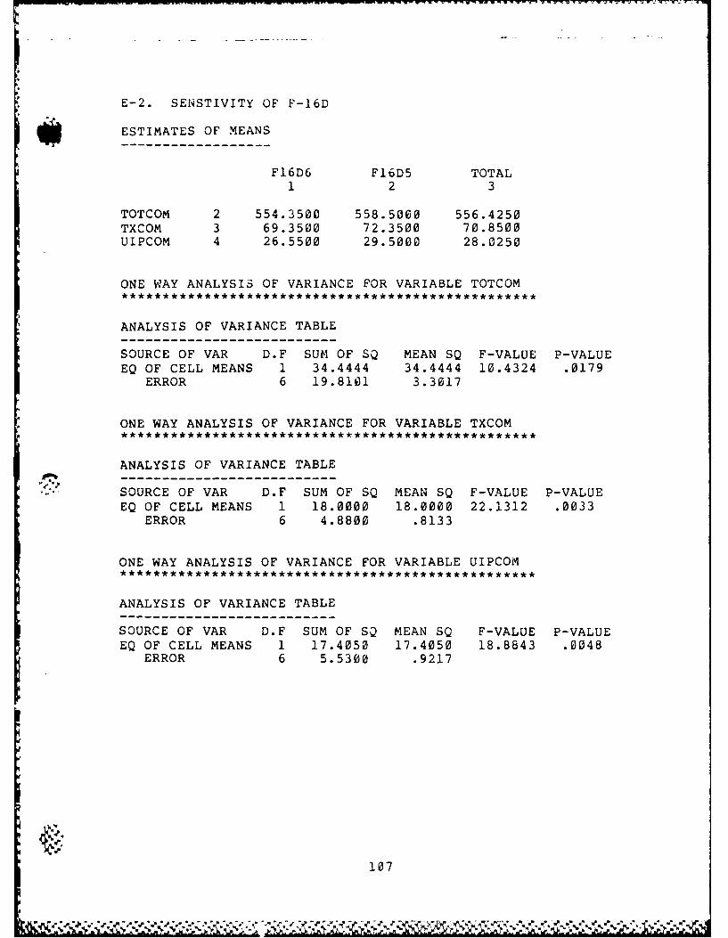
,* E-2. SENSTIVITY OF F-16D
ESTIMATES OF MEANS
F16D6 F16D5 TOTAL1 2 3
TOTCOM 2 554.3500 558.5000 556.4250
TXCOM 3 69.3500 72.3500 70.8500UIPCOM 4 26.5500 29.5000 28.0250
ONE WAY ANALYSIS OF VARIANCE FOR VARIABLE TOTCOM
ANALYSIS OF VARIANCE TABLE
SOURCE OF VAR D.F SUM OF SQ MEAN SQ F-VALUE P-VALUEEQ OF CELL MEANS 1 34.4444 34.4444 10.4324 .0179
ERROR 6 19.8101 3.3017
* ONE WAY ANALYSIS OF VARIANCE FOR VARIABLE TXCOM
ANALYSIS OF VARIANCE TABLE
SOURCE OF VAR D.F SUM OF SQ MEAN SQ F-VALUE P-VALUEEQ OF CELL MEANS 1 18.0000 18.0000 22.1312 .0033
ERROR 6 4.8800 .8133
ONE WAY ANALYSIS OF VARIANCE FOR VARIABLE UIPCOM
ANALYSIS OF VARIANCE TABLE
SOURCE OF VAR D.F SUM OF SQ MEAN SQ F-VALUE P-VALUE
EQ OF CELL MEANS 1 17.4050 17.4050 18.8843 .0048ERROR 6 5.5300 .9217
107
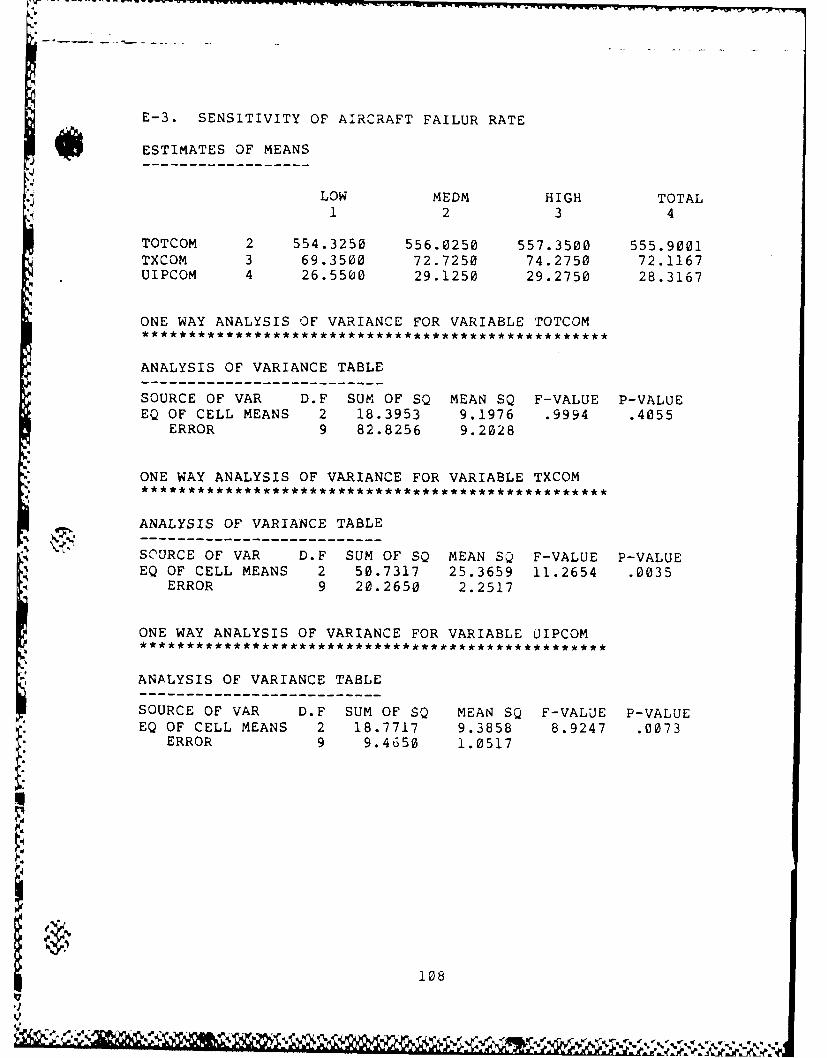
E-3. SENSITIVITY OF AIRCRAFT FAILUR RATE
ESTIMATES OF MEANS
LOW MEDM HIGH TOTAL1 2 3 4
TOTCOM 2 554.3250 556.0250 557.3500 555.9001TXCOM 3 69.3500 72.7250 74.2750 72.1167UIPCOM 4 26.5500 29.1250 29.2750 28.3167
ONE WAY ANALYSIS OF VARIANCE FOR VARIABLE TOTCOM
ANALYSIS OF VARIANCE TABLE
SOURCE OF VAR D.F SUM OF SQ MEAN SQ F-VALUE P-VALUEEQ OF CELL MEANS 2 18.3953 9.1976 .9994 .4055
ERROR 9 82.8256 9.2028
ONE WAY ANALYSIS OF VARIANCE FOR VARIABLE TXCOM** *** ******************* *** **** **** **** ** *
ANALYSIS OF VARIANCE TABLE
SOURCE OF VAR D.F SUM OF SQ MEAN SQ F-VALUE P-VALUEEQ OF CELL MEANS 2 50.7317 25.3659 11.2654 .0035
ERROR 9 20.2650 2.2517
ONE WAY ANALYSIS OF VARIANCE FOR VARIABLE UIPCOM
ANALYSIS OF VARIANCE TABLE
SOURCE OF VAR D.F SUM OF SQ MEAN SQ F-VALUE P-VALUEEQ OF CELL MEANS 2 18.7717 9.3858 8.9247 .0073
ERROR 9 9.4650 1.0517
108
L.%
*
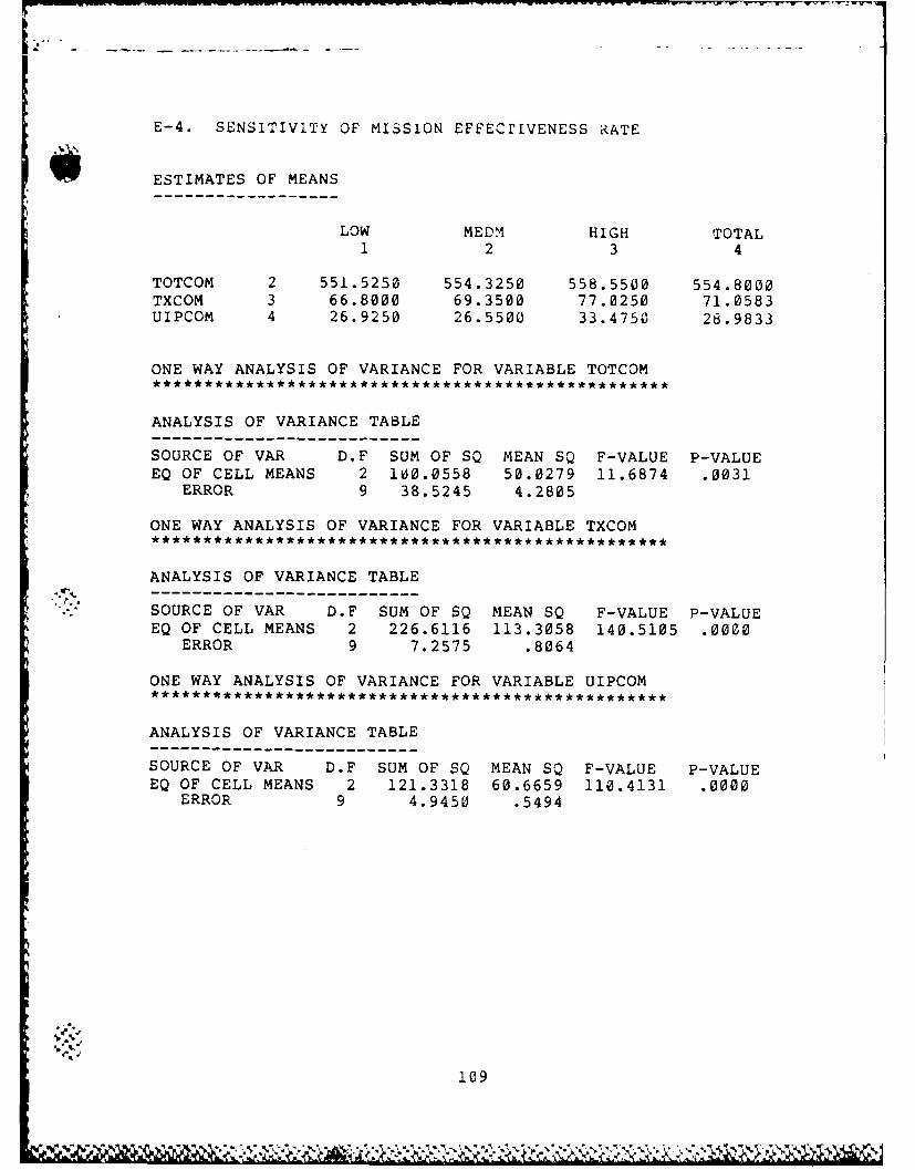
E-4. SENSITIVITY OF MISSION EFFECrIVENESS RATE
ESTIMATES OF MEANS
LOW MEDM HIGH TOTAL1 2 3 4
TOTCOM 2 551.5250 554.3250 558.5500 554.8000TXCOM 3 66.8000 69.3500 77.0250 71.0583UIPCOM 4 26.9250 26.5500 33.4750 28.9833
ONE WAY ANALYSIS OF VARIANCE FOR VARIABLE TOTCOM
ANALYSIS OF VARIANCE TABLE
SOURCE OF VAR D.F SUM OF SQ MEAN SQ F-VALUE P-VALUEEQ OF CELL MEANS 2 100.0558 50.0279 11.6874 .0031
ERROR 9 38.5245 4.2805
ONE WAY ANALYSIS OF VARIANCE FOR VARIABLE TXCOM
ANALYSIS OF VARIANCE TABLE
SOURCE OF VAR D.F SUM OF SQ MEAN SQ F-VALUE P-VALUEEQ OF CELL MEANS 2 226.6116 113.3058 140.5105 .0000
ERROR 9 7.2575 .8064
ONE WAY ANALYSIS OF VARIANCE FOR VARIABLE UIPCOM
ANALYSIS OF VARIANCE TABLE------------------------------SOURCE OF VAR D.F SUM OF SQ MEAN SQ F-VALUE P-VALUEEQ OF CELL MEANS 2 121.3318 60.6659 110.4131 .0000
ERROR 9 4.9450 .5494
109

Appendix F. F-16 Pilot :r-aining Model (SLAM Code)
GEN,YLEF,TRTRN,8/1/85,4,,!";LIMITS,35, 10,500 ;PRIORITY/l,LVF(2)/NCLNR,LV%,F(l);PRICRITY/2,LVF(2)/NCLNR,LVF--(l);PRIORITY/3,LVF(2)/NCLNR,LVF '(1);PRIORITY/4,LVF (2)/NCLNR,LVF (1);PRIORITY/6,LVF(2)/NCLNR,LVF(l);PRIORITY/7,LVF(2)/NCLNR,LVF(l);PRIORITY/8,LVF(2)/NCLNR,LVF7(l);INTLC,XX(1)=8; NUBBER OF CLASSESINTLC,XX(2)=6; TRANsIriow(TX) STUDENT PILOTS(SP)INTLC,XX(3)=2; UPG3RADING INSTRUCTOR PILOTS(UIP)INTLC,XX (4) =0,XX (5) =0,XX (6; '=,XX (7)=@,XX (8) =0,XX (9)=0INTLC,XX(l0)=0,XX(ll)=0,XXJ12)=@,XX(13)=0,XX(15)=0;Ir~rLC,XX (16)=0,XX (17)=0,XX (18)=0,XX(19) =0,XX (20) =0;INTLC,XX(31)=0.025,XX(32)=0.975;
PREFLIGHT CHECK ACFT FAIL RATEINTLC,XX(33)=0.0~67,XX(34)=Z'.933; GROUND ABORT RATEINTLC,XX(35)=0.033,XX(36)=%.967;
PCSTFLIGHT CHECK ACFT FAIL RATEINTLC,'-X(80)=0.17; MISSION EFFECTIVENESS RATE
NETWORK;RESOURCE/IP(4),l/F162(0),2/Fl6D(6),3/AREA(3),4;
INITIAL IP,F16C,F16D, AREA7~. GATE/WX,OPEN,5/DAY,CEN,6,8/ACTR,CLOSE,7;
WX ,DAY ,ACADEMIC (ACAD) GATE
CREATE,659,69,6; CREATE 2 UIPs EVERY 3 MONTHSGOON;ACT, ... UIPT;ACT, ... UIPT;ACT,,,UALT; DU!{MY ENTITY
CREATE,69,...8; CR7ATE 6 SPs EVERY 3 MONTHSGOON;IACT, ...TXTR;ACT, ... TXTR;ACT ...TXTR;
ACT ...TXTR;ACT ...TXTR;
ACT,...TXTR;*ACT ...TALT; DU {MY ENTITY
TALT ALTER,IP/-1; Ch 1N:G7NG 1IP FOR A-ADEMLIC TRiNASSIGN.,XX(12)=XX(12)-l; CLASS NUMBERACT,19,,INIP; GRZUJND ACADEMIC TRAINING(TRN)ACT;GOON, 1;
iwN

ACT,,XX(12).EQ.2,CACl; 2nd CLASSACT,,XX(12).EQ.3,CAC2; 3rd CLASSACT,,XX(12).EQ.8,CAC3; 8tn CLASS (AFTER UIP COMPLETE)
INIP ALTER,IP/1; RETURN 1 IP AFTER ACADEMICSTERM;
CACl GOON; FOR CHANGING AIRCRAFTACT,23; AFTER 1st F-16C ARRIVALALTER,F16C/2; INCREASE 2 F-l6CsTERM;
CAC2 GOON; FOR CHANGING AIRCRAFTACT,46; AFTER 2nd F-l6Cs ARRIVALALTER,F16C/2; 1NCREASE 2 F-l6CsALrER,F16D/-2; DECREASE 2 F-l6DsTERM;
CAC3 ALTER,F16C/-2; DECREASE 2 F-l6C-sTERM;
TXTR GOON;ACT,19; GROUND ACADEMIC TRN
ASSIGN,ATRIB (1) 0 ,ATRIB (2) TNOW,ATRIB (3)=90 ,ATRIB (7)=0,ATRIB(8)=XX(12) ,ATR1B(9)1l;
ATRIB(1): SORTIES FLOWNATRIB(2): STARTING DAY OF FLYINGATRIB(3): ACADEMICS
* ; ATRIB(4: FOR RELEASING AREA IN AIRCRAFT SUBROUTINEATRIB(5): MISSION (MSN) TYPE INDEXATRIB(6): INDEX OF AREA DRAWN(1) OR NOT(0)ATRIB(7: DAILY SORTIE FLOWNATRIB(8): CLASS NUMBERATRIB(9): INDEX OF TX TRN(1) OR UIP TRN(2)
CONT GOON,1;ACT,,ATRIB(1).GE.22.AND.ATRIB(3).GE.225,COLL;
COMPLETE FLY & ACADACT; NOT COMPLETE FLY & ACAD, CONTINUEASSIGN,ATRIB(5)=0,1; RESET MSN TYPE INDEXGOON, 1;
* ACT,,NNGAT(DAY).EQ.0,ASPD;IF NIGHTACT;ASSIGN,ATRIB(7)0O; RESET SORTIE FLOKN PER DAY
ASPD AWAIT(6),DAY,l; WAITING DAYLIGHT HOURSACT, ,NNGAT ( WX) .EQ. 1.AND.ATRIB (3) .LE. 225 ,ACAD;
WX BAD,ACADEMICSACT,,NNGAT(WX).EQ.0.AND.NiNRSCIP).GE..AND.
NNRSC CF16D).GE.1. AND.NNRSC (AREA).GE.1. AND.ATRIB(7) .EQ.0,TFLY;
IP,ACFT,AREA AVAILABLE & NO,-T COMPLETED
%111

ACT,1/24,,CON.T; ELSE, DELAY 1 HRS & CONTINUE
CHECK ACADEMICS PREREQUISITES COMPLETED
TFLY GOON,1;ACT, ,ATRIB (1).GE. 3.AND.ATRIB (1).LE.5.AND.
ATRIB(3) .LE.140,ACAD;ACT, ,ATRIB (1).GE. 7.AND.ATRIB (1).LE. 9.AND.
ATRIB(3) .LE.170,ACAD;ACT, ,ATRIB (1).GE.11.AND.ATRIB (1).LE. 13.AND.
-. ATRIB(3) .LE.210,ACAD;ACT, ,ATRIB (1).GT. 16.AND.ATRIB (1).LE. 18.AND.
ATRIB(3) .LE.225,ACAD;ACT;
ASSIGN # OF SPs LEFT FOR MISSIONS REQUIRING 2 SPs
ASSIGN,XX(21)=XX(2) *ATRIB(8)-NNCNT(33)-NNCNT(46),XX(22)=XX(2) *ATRIB(8)-NNCNT(34)-NNCNT(47),XX(23)=XX(2)*ATRIB(8)-NNCNiT(42)-NNCNT(43)-
NNCNT(63),XX (24) =XX (2) *ATRIB (8) -NNCNT (40) -NNCNT (44)-
NNCNT(64);I ASSIGN,XX(25)=XX(2) *ATRIB (8)-NNCNT(41)-NNCNT(45)-
NNCNT(65)rXX(26)=XX(2)*ATRIB(8)-NNc-NT(35)-NNCNT(56),XX (27) =XX(2) *ATRIB (8)-NNCNT (36)-NNCNT (58),XX(28)=XX(2)*ATRIB(8)-NNCT(37)-NNCNT(61),l;
DETERMINE MISSION TYPE ACCORDING TO # OF SPs,# OF IPs, # AND TYPE OF AIRCRAFT
AC-T, ,ATRIB (1).EQ.0,TYPl;ACT, ,ATRIB(1) .EQ.1,TYPl;
ACT, ,ATRIB (1).EQ.2.AND.XX (21) .NE. 1,TYP3;ACT,,ATRIB(1).EQ.2.AND.XX(21).EQ.1,TYP8;ACT, ,ATRIB (1).EQ.3.AND.XX (22) .NE.1,TYP3;
I, ACT,,ATRIB(l).EQ.3.AND.XX(22).EQ.1,TYP8;ACT,,ATRIB(.i).EQ.4.AND.NNRSC(Fl6C).GE.2,TYP2;ACT,,ATRIB(l).EQ.4.AND.NNRSC(Fl6C).LT.2,TYP8;ACT,,ATRIB(1).EQ.-.5.AND.NNRSC-(Fl6C).EQ.0,TYP8;ACT,,ATRIB(l).EQ.5.AND.NNRSC(Fl6C).GE.1,TYP4;ACT,,ATRIB(1).EQ.6.AND.NNRSC(Fl6C).EQ.0,TYP8;ACT,,ATRIB(l).EQ.6.AND.NNRSC(Fl6C).GE.1,TYP4;
ACT, ,ATRIB (1).EQ.7.AND.XX (23) .EQ.1,TYP9;ACT, ,ATRIB (1).EQ.7 .AND.XX (23) .NE.l.AND.
NNRSC(F16C) .LT'.2,TYP7;ACT, ,ATRIB (1).EQ.7 .AND.XX (23) .NE.l.AND.
NNRSC (Fl6C) .GE.2,T*YPG;ACT,,ATRIB(l).EQ.8.AND.NNRSC(Fl6C).LT.2,TYP8;ACT,,ATRIB(l).EQ.8.AND.NNRSC(Fl6C).GE.2,TYP2;ACT,,ATRIB(l).EQ.9.AND.NN4RSC(Fl6C).LT.2,T'YP8;
112
-U&

ACT,,ATRIB(1).EQ.9.AN;D.NNRSC(FI6C).GQE.2,TIYP2;ACT,,ATRIB(1).EQ.10.AND.NNRSC(Fl6C).LT'.2,TYP8;ACT,,ATRIB(l).EQ.1k0.AND.NNRSC(Fi6C).GE.2,TYP2;ACT,,ATRIB(1).EQ.11.AND.NNRSC(Fl6C).LT:.2,TYP8;ACT-,,,ATRIB(l).EQ.1.AND.NNRsC(F16C).GE.2,TYP2;ACT,,ATRIB(1).EQ.12.AND.N4NRSC-(F16C).LT.2,TYP8;ACT,,ATRIB(1).EQ.12.AND.NNRSC(Fl6C).GE.2,TYP2;ACT,,ATRIB(1).EQ.13.AND.XX(24).EQ.1,TYP9;ACT, ,ATRIB (1).EQ.13.AND.XX (24) .NE.l.AND.
NNRSC(F16C) .GE.3,TYP5;ACT,,ATRIB(1).EQ.13.AND.XX(24).NE.l.AND.
NNRSC(F16C) .LT.3,T'YP7;ACT,,ATRIB(l).EQ.14.AND.XX(25).EQ.1,TYP9;ACT, ,ATRIB (1).EQ.14.AND.XX (25) .NE. 1.AND.
NNRSC(F16C) .GE.3,TYP5;ACT,,ATRIB(l).EQ.14.AND.XX(25).NE.l.AND.
NNRSC(F16C) .LT.3,TYP7;ACT,,ATRIB(l).EQ.15.AND.XX(26).EQ.1,TYP8;ACT, ,ATRIB (1).EQ.15.AND.XX(26) .NE.1,TYP3;ACT,,ATRIB(l).EQ.16.AND.NNRSC(F16C).LT.2,TYP8;ACT,,ATRIB(l).EQ.16.AND.NNRSC(F16C).GE.2,TYP2;ACT,,ATRIB(l).EQ.17.AND.XX(27).EQ.1,TYP8;ACT,,ATRIB(l).EQ.17.AND.XX(27).NE.1,TYP3;ACT, ,ATRIB (l).EQ. 18 .AND.NNRSC (Fl6C) .LT.2 ,TYP8;ACT,,ATRIB(l).EQ.18.AND.NNRSC(Fl6C).GE.2,TYP2;ACT,,ATRIB(l).EQ.19.AND.NNRSC(Fl6C).LT.2,TYP8;ACT,,ATRIB(l).EQ.19.AND.NNRSC(F16C).GE.2,TYP2;ACT,,ATRIB(1).EQ.20.AND.XX(28).EQ.1,TYP8;ACT, ,ATRIB (1).EQ.20.AND.XX(28) .NE.1,TYP3;ACT,,ATRIB(l).EQ.2l.AND.NNRSC(Fl6C).LT.2,TYP8;ACT,,ATRIB(l).EQ.2l.AND.NNRSC-(F16C).GE.2,TYP2;
ACADEMIC TRAINING SUBROUTINE
ACAD GOON,1;A!CT,1/24,XX (8) .GE. 8,CONT;
IF ACAD HRS/DAY GE 8HRS, DELAY & CONTACT;ASSIGN,XX(4)=XX(4)+1; FOR DRAW'ING ALL SPsACT, ,XX (4).EQ .XX (2) .OR .NNGAT (DAY) EQ .1, ALSP;
ALL SPs DRAWED & DAYACT;AWAIT(7),ACTR; AWAIT UNTIL ALL SPs GATHEREDGOON, 1;ACT,,NNGAT(DAY).EQ.1,NITE; IF NOT DAY, GO TO NITEACT;ASSIGN,XX(4)=XX(4)-l;
FOR CLOSING ACADEMIC TRAINING GATEACT, ,XX(4) .EQ.0,NASP;
AFTER SPs PASSED, GO TO CLOSING GATEACT;
GOON, 1;

ACT,.33/24,NNRSC (IP).EQ.0,CONT;ACT;GOON, 1;ACT,,NNRSC-(IP).GT.0.AND.XX(5).EQ.1,NOIP;
FOR DRAWING 1 IPACT;AWAIT(1),IP; DRAW 1 IPASSIGN,XX(5)=1; FOR NOT DRAWING IP
NOIP GOON;ACT,1/24; ACADEMIC TRAINING 1 HOURGOON, 1;ACT,,XX(5).EQ.0,NFIP; FOR NOT RELEASING IPACT;ASSIGN,XX (5) =0,XX (8)=XX (8) +1;INCREASE DAILY ACAD HOURSFREE, IP; RELEASE 1 IP
NFIP ASSIGN,ATRIB(3)=ATRIB(3)+1; INCREASE ACADEMIC HOURSACT,,NNGAT(DAY).EQ.1,NASP; NITE, CLOSE ACAD TRN GATEACT,...CONT; CONTINUE
ALSP OPEN,ACTR; OPEN ACAD TRN GATETERM;
VNITE ASSIGN,XX(4)=0; RESET SP COUNTERACT,...CONT; RETURN AND CONTINUE
NASP CLOSE,ACTR; CLOSE ACAD TRN GATETERM;
WX CANCEL SUBROUTINE
CREATE;,~~ WXC ASSIGN,XX(6)=USERF(2),1; DRAW WX CANCEL(CNX) RATE
ACT,,XX(6),CNX; IF WX BADACT,,1-XX(6),OPN; IF WX GOOD
CNX CLOSE,WX; CLOSE WX GATEEVENT, 1;
ASSIGN,XX (13) =0,XX (14) =0,XX (15) =0,XX (20) =0;ACT,4/24,,WXC; EVERY 4 HOUR DRAW WX CNX RATE
OP14 EVENT,1;OPEN,WX; OPEN WX GATEACT,4/24,,WXC; EVERY 4 HOUR DRAW WIX CNX RATE
DAYLIGHT HOUR SUBROUTINE
4 CREATE;NDAY OPEN,DAY; OPEN DAYLIGHT GATE
CLOSE,ACTR;ASSIGN,XX(7)=USERF(3); DRAW DAYTIME HOURSACT,XX(7); DAYTIMECLOSE,DAY; CLOSE DAYLIGHT GATEASSIGN ,XX (8) =O,XX (13) =0,XX (14) =0,
XX(15)=O,XX(20)=0; RESET DAILY COUNTEREVENT,1; RELEASE SPs WAITING IPs, ANOTHER SPS
OPEN,ACTR; OPEN ACADEMIC TRAINING GATEACT,1-XX(7) ,,NDAY; NIGHT
'~ 114

COLLECT DAYS COMPLETED
COLL ASSIGN,XX(9)=TNOW-ATRIB(2)+19,XX (10j) =TNDvi-ATRIB (2) -50,XX (11) =XX (11) +1;
XX(9): COMPLETE DAYSXX(10): LATE DAYSXX(11): COUNTING ALL SPs IN A CLASS
COLCT,XX(9) ,COMPLETE DAYS OF SP;GOON, 1;AC-T,,XX(11).EQ.XX(2),NOCL; IF ALL SPs COMPLETEDACT; ELSETERM, 43;
NOCL COLCT,XX(9) ,COMPLETE DAYS OF CLASS;ASSIGN ,XX (9) =0,XX (10) =0,XX (11) =0,XX (21) =0,XX (22) =0,
XX(23)0O,XX(24)=0,XX(25)=0,XX(26)=0,XX(27)=0;TERM,8; ALL CLASSES COMPLETED
*TX MISSION TYPE 1***1 SP, 1 IP, 1 F16D
TYPi ASSIGN,ATRIB(5)=1,ATRIB(6)=O;ASSIGN MSN TYPE, INDEX # OF AREA
AWAIT(i),IP; DRAW IPACT,1.5/24; PREBRIEFINGAWAIT(3)fF16D; DRAW AIRCRAFT
TY1PF GOON,1;ACT,.5/24,XX(31),BR1D;PREFLIGHT CHECK, 1 F-16D FAILUREACT,.5/24,XX(32); AIRCRAFT NOT FAILUREGOON~lACTI, NNGAT (WX ).EQ.1. OR. NNGAT (DAY).EQ.1, WABl;
BAD WX & NIGHT, ABORTACT, .49/24;AWAIT(4),AREA; DRAW AIRWORK AREAASSIGN,ATRIB(6)=1,1; INDICATES AREA DRAWEDACT,,XX(33),BR1D; GROUND ABORTACT,1.28/24,XX(34); FLY MSNFREE,AREA; RELEASE AREAACT... PSC1; ACFT POSTFLIGHT CHECKACT,1/24; DEBRIEFINGFREE,IP; RELEASE IPGOON, 1;ACT,1/24,XX(,-0) ,CONr; NOT EFFECTlVE MSN, CONTINUEACT;GOON, 1; ASSIGN SORTIE COMPLETED
115
ACT/21L,,ATRl (1) .EQ.0,ASN1;
ACT/22,,ATRIB(l).EQ.1,ASN2;
doASNi ASSIGN,ATRIB (1)1 ,ATRIB (7) =1;ACT,1/24,,CONT; RETURN TO CONTINUEING NODE
ASN2 ASSIGN,ATRIB(1)=2,ATRIB(7)=1;ACT,1/24, ,CONT;
*TX MISSION TYPE 21 sp, 1 IP, 2 F16C
TYP2 ASSIGN,ATRIB(5)=2,ATRIB(6)=0;AWAIT (1) , IP; DRAW. 1 IPACT ,1. 5/24;AWAIT(2),Fl6C/2; DRAW4 2 F16C
TY2PF GOON,1;ACT,.5/24,2*XX(31)*XX(32),BR1C; 1 F16C FAILURE
ACT,.5/24,XX(31)*XX(31),BR2C; 2 F-16Cs FAILUREACT,.5/24,XX(32)*XX(32); ALL ACET OKGOON~lACT ,, NNGAT (WX ) EQ.1. OR.NNGAT (DAY).EQ.1, WAB2;ACT, .49/24;AWJAIT(4) ,AREA;
ASSIGN ,ATRIB (6) =1,1;ACT,,2*XX(33)*XX(34),BR1C; 1 F-16C FAIL
ACT,,XX(33)*XX(33),BR2C; 2 F-16C FAILACT,1.28/24,XX(34)*XX(34); FLY MSNFREE,AREA;ACT, ... PSC2;
* ACT,1/24;FREE,IP; RELEASE 1 IP
GOON, 1;ACT,1/24,XX(80) ,CONT;ACT;GOON, 1;ACT/23,,ATRIB(1).EQ.4,AS5P;ACT/24,,ATRIB(l) .EQ.8,AS9P;ACT/25, ,ATRIB(1) .EQ.9,AliOP;ACT/26,,ATRIB(l) .EQ.10,Al1P;ACT/27,,ATRIB(1) .EQ.11,A12P;ACT/28,,ATRIB(1) .EQ.12,A13P;ACT/29,,ATRIB(1).EQ.16,Al7P;ACT/30,,ATRIB(l).EQ.18,A19P;ACT/31,,ATRIB(1) .EQ.19,A20P;
ACT/32,,ATRIB(l).EQ.21,A22P;AS5P ASSIGN,ATRIB (1)=5 ,ATRIB (7) =1;
ACT,1/24, ,CONT;AS9P ASSIGN,ATRIB (1)=9,ATRIB (7) =1;
ACT,1/24, ,CONT;A1OP ASSIGN,ATRIB (1) =10 ,ATRIB (7) =1;
ACT,1/24, ,CONT;AllY ASSIGN,ATRIB(1)=11,ATRIB(7)=l;
ACT,1/24, ,CONT;
116

A12P ASSJ-GN,ATRIB (1)=12,ATRIB (7)1l;ACT,1/24, ,CONT;
A13P ASS.lGN,ATRIB(1)=13,ATRIB (7)1l;ACT,1/24, ,CONT;
A17P ASSIGN,ATRIB (1) =17,ATRIB (7)1l;ACT,1/24, ,CONT;
A19P ASSIG-N,ATRIB(1)=19,ATRIB(7)=1;ACT,1/24, ,CONT;
A20P ASSIGN,ATRIB (1)=20,ATRIB (7) =1;ACT,1/24, ,CONT;
A22P ASSIGN,ATRIB(1)=22,ATRIB(7h2l;ACT,1/24,,CONT;
STX MSN TYPE3 $ UIIP MSN TYPE 2***2 SP, 2 IP, 2 F16D
TYF3 ASSIGN,ATRIB(5)=3,ATRIB(6)=O;GTY3 GOON,1;
ACT, ,XX(13) .EQ.0,FPLT;ACT, ,XX(13) .EQ.1,SPLT;
FPLT ASSIGN,XX(13)=1;ACT, ... QONE;
SPLT ASSIGN,XX(13)=0;ACT ...QTWO;
QONE QUEUE(11),....MATC; WAITING ANOTHER SPQTWO QtJEUE(12),....MATC; WAITING ANOTHER SPMATC MATCH,1,QONE/MAA,QTWO/MAA; NEXT MSN SAMEMAA ACCUM,2,2,LAST; DRAW 2 SPs
*AWAIT(l),IP/2; DRAW 2 IPsACT ,1. 5/24;AWAIT(3),Fl6D/2; DRAW 2 F-l6Ds
TY3PF GOON,1;ACT,.5/24,2*XX(31)*XX(32),BR1D; 1 F-16D FAILACT,.5/24,XX(31)*XX(31),BR2D; 2 F-l6Ds FAILACT,.5/24 ,XX (32) *XX (32);GOON, 1;ACT, ,NNGAT (WX ).EQ.1. OR. NNGAT (DAY).EQ.1, WAB3;ACT, .49/24;AvWAIT(4) ,AREA,ASSIGN,ATRIB (6) =1,1;
*ACT,,2*XX(33)*XX(34),BR1D; 1 F-16D FAILACT,,XX(33)*XX(33),BR2D; 2 F-l6Ds FAILACT,1. 28/24 ,XX (34) *XX( 34);FREE, AREA;ACT, ... PSC3;ACT, 1/24 ;FREE, IP/2; RELEASE 2 IPsACT;ACT;GOON, 1;ACT,,ATRIB(5).EQ.12,GUI2; RETURN TO UIP MSN
TYPE 2
11

ACT;GOON , 1;AC-T,1/24,XX(80) ,C-ONT;ACT;GOON, 1;AC-T/33,,ATRIB(1).EQ.2,ASN3;
ACT/34, ,ATRIB (1).EQ.3,ASN4;ACT/35,,ATRIB(1).EQ.15,AS16;ACT/36, ,ATRIB(1) .EQ.17,AS1B;ACT/37,,ATRIB(1).EQ.20,AS21;
ASN3 ASSIGN,ATRIB(1)=3,ATRIB(7)=1;ACT,1/24, ,CONT;
ASN4 ASSIGN,ATRIB(1)=4,ATRIB(7)=1;ACT,1/24, ,CONT;
AS16 ASSIGN,ATRIB (1)=16,ATRIB (7) =1;ACT,1/24, ,CONT;
AS18 ASSIGN,ATRIB(1)=18,ATRIB(7)1l;ACT,1/24,,CONT;
AS21 ASSIGN,ATRIB(1)=2l,ATRIB(7)=1;ACT, 1/24 ,,CONT;
**~TX MISSION TYPE 4 $ UIP MSN TYPE 4***1 SP, 2 IP, 1 F16C, 1 F16D
TYP4 ASSIGN,ATRIB(5)=4,ATRIB(6)=O;GTY4 AWAIT(1),IP/2; DRAW 2 IPs
ACT,1.5/24;AWAIT(2),F16C; DRAW 1 F-16CAWAIT(3),F16D; DRAW I F-16D
TY4PF GOON,1;ACT,0.5/24,XX(31)*XX(32),BRCI; 1 F-16C FAIL
NACT,0.5/24,XX(31)*XX(32),BRD1; 1 F-16D FAIL* ACT,0.5/24,XX(31)*XX(31),BC1Dl;1 F-16C, 1 F-1ED FAIL
ACT ,0 5/24 ,XX (32) *XX (32);* GOON,1;
AC-T, ,NNGAT (WX ).EQ .1.OR.NNGAT (DAY).EQ .1,WAB4;ACT,.49/24;AWAIT(4) ,AREA;ASSIGN ,ATRIB (6) =1,1;ACT,,XX(33)*XX(34),BRC1; 1 F-16C FAILACT,,XX(33)*XX(34),BRDl; 1 F-16D FAILACT,,XX(33)*XX(33),BC1D1; 1 F-16C, 1 F-16D FAILACT,1. 28/24 ,XX (34) *XX (34);FREE,AREA;ACT,...PSC4;ACT ,1/24;FREE, IP/2; RELEASE 2 IPsGOON, 1;ACT, ,ATRIB(5) .EQ.14,GU14; RETURN TO UIP MSN 4ACT;GOON, 1;AC-T,1/24,XX(80) ,CONT;
V *?*A~118

ACT;* GOON, 1;
ACT/3d, ,ATRIB (1).EQ.5,AS6P;ACT/39,,ATRIB(l).EQ.6,AS7P;
AS6P ASSIGN,ATRIB (1)=6,ATRIB3(7)=1;ACT,1/24, ,CONT;
AS7P ASSIGN,ATRIB(1)=7,ATRIB(7)=1;ACT,1/24, ,CONT;
*TX MISSION TYPE 51 SP, 2 IP, 3 F16C
TYP5 ASSIGN,ATRIB (5)=5 ,ATRIB (6) =0;AWAIT(1) ,IP/2; DRAW~ 2 IPsACT, 1.5/24;AWAIT(2) ,F16C/3; DRAWJ 3 F-l6Cs
TYSPF GOON,1;ACT,0.5/24,3*XX(31)*XX(32)*XX(32),BR1C; 1 F-16C FAILACT,0.5/24,3*XX(31)*XX(31)*XX(32),BR2C; 2 F-l6Cs FAILACT,0.5/24,XX(31)*XX(31)*XX(31),BR3C; 3 F-16Cs FAILACT,0.5/24,XX(32)*XX(32)*XX(32);GOON, 1;ACT, ,NNGAT (WX) .EQ. 1. OR .NNGAT (DAY ) .EQ.1, WAB5;ACT,.49/24;AWAIT(4) ,AREA;ASSIGN,ATRIB(6)=1,1;ACT,,3*XX(33)*XX(34)*XX(34),BR1C; 1 F-16C FAILACT,,3*XX(33)*XX(33)*XX(34),BR2C; 2 F-l6Cs FAILACT,,XX(33)*XX(33)*XX(33),BR3C; 3 F-16Cs FAIL
ACT ,1. 28/24 ,XX (34) *XX (34) *XX (34);FREE,AREA;ACT,...PSC5;ACT, 1/24;FREE, IP/2; RELEASE 2 IPsGOON~lACT,1/24,XX (80) ,CONT;ACT;GOON~lACT/40, ,ATRIB (1).EQ.13,A14P;ACT/41,,ATRIB(1) .EQ.14,A15P;
A14P ASSIGN,ATRIB(1)=14,ATRIB(7)1l;ACT,1/24, ,CONT;
A15P ASSIGN,ATRIB(1)=15,ATRIB (7)1l;ACT,!/24, ,CONT;
*TX MISSION TYPE 6 & UIP MESN TYPE 3***2 SP, 2 IP, 2 F16C, 1 F16D
TYP6 ASSIGN,ATRIB(5)=6,ATRIB(6)=0;GTY6 GOON,1;
ACT, ,XX (14) .EQ. 0,FTPL;
F 119

- - - - - - - -
* ACT,,XX(14)EQl1SDPL;FTPL ASSIGN,XX(14)1l;
* ACT,, ,QTHRE;SDPL ASSIGN,XX(14)=0;
ACT, ...QFOtJR;QTHRE QUEUE(13) ....,MTCH;QFOUR QUEUE(J.4) ....MTCH;MTCH MATCH ,1, QTHRE/MAB ,QFOEJR/MAB;MAB ACCUM,2,2,LAST;
AWAIT(1) ,IP/2; DRAW 2 IPsACT ,1.5/24;AWAIT(2) ,F16C/2; DRAW 2 F-l6CsAWAIT(3) ,F16D; DRAW 1 F-16D
TY6PF GOON,1;ACT,.5/24,XX(31)*XX(32)*XX(32),B1D6M~; 1 F16D FAILACT,.5/24,2*XX(31)*XX(32)*XX(32),B1C6M; 1 F16C FAILACT,.5/24,XX(31)*XX(31)*XX(32),B2C6OM; 2 F16C FAILACT,.5/24 ,2*XX (31) *XX (31) *XX (32) ,C1D1B;
1 F16C, 1 F16D FAILACT,.5/24 ,XX (31) *XX (31) *XX (31) ,B2C1D;
2 F16C, 1 F16D FAILACT, 5/24 ,XX (32) *XX (32) *XX (32);GOON~lACT,,NNGAT(WX).EQ.1.OR.NNGAT(DAY).EQ.1,WAB6;ACT, .49/24;AWAIT(4) ,AREA;ASSIGN ,ATRIB (6) =1,1;ACT,,XX(33)*XX(34)*XX(34),B1D6M; 1 F16D FAILACT,,2*XX(33)*XX(34)*XX(34),B1C6M; 1 F16C FAILACT,,XX(33)*XX(33)*XX(34) ,B2C6M; 2 F16C FAILACT,,2*XX(33)*XX(33)*XX(34),C1DlB; 1 F16C, 1 F16D FAILACT,,XX(33)*XX(33)*XX(33),B2ClD; 2 F16C, 1 F16D FAILACT ,1. 28/24 ,XX (34) *XX (34) *XX (34);FREE,AREA;ACT,,. PSC6;ACT, 1/24;FREE, IP/2;ACT;ACT;GOON~lACT,,ATRIB(5).EQ.13,GUI3; RETURN TO UIP MSN TYPE 3ACT;GOON~lAC-T, 1/24 ,XX( 80) ,CONT;ACT;ASSIGN,ATRIB (1)=8,ATRIB (7)=l;ACT/42,1/24, ,CONT;
;* *TX MSN TYPE 7 **
2 SP, 2 IP, 3 F16D
TYP7 ASSIGN,ATRIB (5) =7 ,ATRIB C6) =0,1;
-N,. 120
ACT,,XX(15) .EQ.0,FRTP;ACT,,XX(15).EQ.1,SCDP;
FRTP ASSIGN,XX(15)=1;ACT, ...QFIVE;
SCDP ASSIGN,XX(15)=O;ACT, ...QSIX;
QFIVE QUEUE(15) ....MACH;QSIX QUEUE(16),....MACH;MACH MATCH,1 ,QFIVE/MAC,QSIX/MAC;MAC ACCUM,2,2,LAST;
AWAIT(1) ,IP/2; DRAW 2 IPsACT ,1. 5/24;AWAIT(3) ,F16D/3; DRAW 3 F-16DS
TY7PF GOON,1;ACT,.5/24,3*XX(31)*XX(32)*XX(32),BD7M4; 1 F16D FAILACT,.5/24,3*XX(31)*XX(31)*XX(32),B2D7M; 2 F16D FAILACT,.5/24,XX(31)*XX(31)*XX(31),B3D7M; 3 F'16D FAILACT,.5/24 ,XX (32) *XX (32) *XX (32);GOON, 1;ACT,,NNGAT(WX).EQ.1.OR.NNGAT(DAY).EQ.1,WAB7;ACT, .49/24;AWJAIT(4) ,AREA;ASSIGN,ATRIB(6)=1,1;ACT,,3*XX(33)*XX(34)*XX(34),B1D7M; 1 F16D FAILACT,,3*XX(33)*XX(33)*XX(34),B2D7M; 2 F16D FAILACT,,XX(33)*XX(33)*XX(33),B3D7M; 3 F16D FAILACT,1. 28/24 ,XX (34) *XX (34) *XX (34);FREE,AREA;ACT,,, PSC7;ACT, 1/24;FREE,IP/2;ACT;ACT;GOON, 1;ACT,1/24,XX(80) ,CONT;ACT;GOON, 1;ACT/43,,ATRIB(1).EQ.7,AS8S;ACT/44,,ATRIB(1).EQ.13,A14S;ACT/45,,ATRIB (1).EQ.14,A15S;
*AS8S ASSIGN,ATRIB(1)=8,ATRIB(7)=1;ACT,1/24,,CONT;
A14S ASSIGN,ATRIB(1)=14,ATRIB(7)1l;ACT,1/24,,CONT;
A15S ASSIGN,ATRIB(1)=15,ATRIB(7)1l;ACT,1/24, ,CONT;
**~TX MISSION TYPE 8 & UIP MSN TYPE 5***1 SP, 2 IP, 2 F16D
TYP8 ASSIGN,ATRIB(5)=8,ATRI3(6)=J;-GTY8 AWAIT(1),IP/2; DRAW 2 IPs
*.,.,121

ACT,1.5/24;AWAIT(3),F16-D/2; DRAWi 2 F-lbDs
TY8PF GOON,1;AC-T,.5/24,2*XX(31)*YX(32),BRlD; 1 F-16D FAILACT,.5/24,XX(31)*XX(31),BR2D; 2 F-16Ds FAILACT,.5/24 ,XX (32) *XX (32);GOON, 1;ACT, ,NNGAT (WX).EQ.1. OR. NNGAT (DAY ).EQ.1, WABS;ACT, .49/24;
AvWAI T(4) ,AREA;ASSIGN,ATRIB (6)=11
4.; ACT,,2*XX(33)*XX(34),BRlD;ACT, ,XX (33)*X( 33) ,BR2D;ACT,1. 28/24 ,XX (34)*X(34);FREE, AREA;ACT,, ,PSC3;ACT, 1/24;FREE, IP/2;GOON~lACT, ,ATRIB(5) .EQ.15,GUI5; RETURN TO IJIP MSN TYPE 5ACT;GOON, 1;ACT, 1/24 ,XX (80) ,CONT;ACT;GOON , ;ACT/46,,ATRIB(1).EQ.2,AS3A;ACT/47,,ATRIB(1).EQ.3,AS4A;ACT/48, ,AT.RIB(1) .EQ.4,AS5A;
* ACT/49,,ATRIB(1).EQ.5,AS6A;ACT/50,,ATRIlB(l).EQ.6,AS7A;ACT/51,,ATRIB(1) .EQ.8,AS9A;ACT/52,,ATRIB(1).EQ.9,AliA;ACT/53,,ATR.IB(1) .EQ.10,A11A;ACT/54,,ATRIB(1).EQ.11,Al2A;ACT/55,,ATRIB(l).EQ.12,A13A;ACT/56, ,ATRIB (1).EQ.15,A16A;ACT/57,,ATRIB(1).EQ.16,A17A;ACT/58,,ATRIB(i).EQ.17,AI8A;ACT/59,,ATR.IB(l).EQ.18,A19A;ACT/60,,ATRIB(1) .EQ.19,A20A;ACT/61,,ATRIB(1).EQ.20,A21A;ACT/62,,ATRIB(1) .EQ.21,A22A;
AS3A ASSIGN,ATRIB(1)=3,ATRIB(7)1l;ACT,1/24, ,CONT;
AS4A ASSIGN,ATRIB(1)=4,ATRIB(7)=1;ACT, 1/24 , ,CON- .7
AS5A ASSIGN,ATRIB(1)=5,ATRIB(7)1l;
ACT,1/24,,CONT;AS6A ASSIGN,ATRIB(1)=6,ATRIB(7)=l;
ACT,1/24,,CONT;AS7A ASSIGN,ATRIB(1)=7,ATRIB(7)1l;
AC-T,1/24,,CONT;
122

AS9A ASSIGN,ATRIB(1)=9,ATRI3(7)=1;ACT,1/24, ,CONT;
A10A ASSIGN,ATRIB(1)=10,ATRIB(7)1l;ACT,1/24, ,CONT;
A11A ASSIGN,ATRIB(1)=11,ATLRIB(7)1l;ACT,1/24, ,CONT;
A12A ASSIGN,ATRIB (1) =12 ,ATRIB (7) =l;
ACT,1/24, ,CONT;A13A ASSIGN,ATRIB (1)=13,ATRIB (7) =1;
ACT,1/24, ,CONT;A16A ASSIGN,ATRIB (1) =16,ATRlB (7) =1;
ACT,1/24, ,CONT;A17A ASSIGN,ATRIB (1)=17,ATRIB(7)=1;
ACT,1/24, ,CONT;A18A ASSIGN,ATRIB(1)=18,A'RIB(7) =1;
ACT,1/24, ,CONT;A19A ASSIGN,ATRIB(1)=19,ATRIB(7)=1;
ACT,1/24, ,CONT;A20A ASSIGN,ATRIB(1)=20,ATRIB(7)1l;
ACT,1/24, ,CONT;A21A ASSIGN,ATRIB(1)=21,ATRIB(7)1i;
ACT,1/24, ,CONT;A22A ASSIGN,ATRIB(1)=22,ATRIB(7)1l;
ACT,1/24, ,CONT;
STX MISSION TYPE 9***1 SP, 2 IP, 3 F16D
TYP9 ASSIGN,ATRIB(5)=9,ATRIB(6)=0;AWAIT(1) ,IP/2; DRAW 2 IPsACT,1.5/24;AWAIT(3) ,F16D/3; DRAW 3 F-l6Ds
TY9PF GOON,1;ACT,.5/24,3*XX(31)*XX(32)*XX(32),B1D7M; 1 F16D FAILACT,.5/24,3*XX(31)*XX(31)*XX(32),B2D7M; 2 F16D FAILACT,.5/24,XX(31)*XX(31)*XX(31),B3D7M; 3 F16D FAILACT, .5/24 ,XX (32) *XX (32) *XX (32);GOON~lACT ,, NNGAT (WX) .EQ.1. OR NNGAT (DAY ). EQ.1, WAB9;ACT, .49/24;AWAIT(4) ,AREA;ASSIGN,ATRIB (6) =1,1;
ACT,,3*XX(33)*XX(34)*XX(34),B1D7M; 1 F16D FAILACT,,3*XX(33)*XX(33)*XX(34),B2D7M; 2 F16D FAILACT,,XX(33)*XX(33)*XX(33),B3D7M; 3 F16D FAILACT,i.28/24,XX(34) *XX(34) *XX(34);FREE,AREA;ACT,,. PSC7;ACT, 1/24;FREE, IP/2;
GOON~l
u - 123

ACT,l,'24,XX (80),CONT;ACT;GOON,l;ACT/63,,ATRiB(l).EQ.7,AS8A;
ACT/64,,ATRIB(l).EQ.13,Al4A;ACT/65,,ATRIB(l).EQ.14,Al5A;
ASBA ASSIGN,ATRIB(1)=8,ATRIB(7)1l;ACT,1/24, ,CONT;
A14A ASSIGN,ATRIB (1) =14 ,A'TRIB (7) =1;ACT,1/24, ,CONT;
A15A ASSIGN ,ATRIB (1) =15 ,ATRIB (7)=1;ACT,1/24, ,CONT;
SACET POST-FLIGHT CHECK***
PSC1 QUEUE(21);ACT,.5/24,XX(35),RP11O; 1 P-16D FAILUREACT, .5/24 ,XX (36); ACFT OKFREE,F16D; RELEASE ACFTTERM;
PSC2 QUEUE(22);ACT(2),.5/24,2*XX(35)*XX(36),RLlC2; 1 F16C FAILUREACT(2),.5/24,XX(35)*XX(35),RP2C; 2 F16C FAILUREACT(2),.5/24,XX(36)*XX(36); ACFT OKFREE,F16C/2;TERM;
PSC3 QUEUE(23);ACT (2) ,. 5/24 ,2*XX (35)*X( 36) ,RL1D1;ACT (2) ,.5/24 ,XX (3 5)*XX (35) ,RP2D;ACT (2) ,. 5/24 ,XX (36)*X(36);FREE,F16D/2;TERM;
PSC4 QUEUE(24);ACT(2),0.5/24,XX(35)*XX(36),R1FC; 1 F16D FAILACT(2) ,0.5/24,XX(35)*XX(36) ,R1FD; 1 F16C FAILACT(2),0.5/24,XX(35)*XX(35),RC1D1; 1 F16C, 1 F16D
FAILAC-T(2),0.5/24,XX(36)*XX(36); NO ACFT FAILFREE,F16C;FREE,F16D;TERM;
PSC5 QUEUE(25);ACT(3),0.5/24,3*XX(35)*XX(36)*XX(36),RL1C2;ACT (3) ,0. 5/24 ,3*XX (35) *XX (3 5)*XX (36) ,RL2C2;ACT (3) ,0. 5/24 ,XX (35) *XX (35) *XX (3 5) ,RPSC;ACT( 3) ,0. 5/24 ,XX (36) *XX (36) *XX (36);FREE,F16C/3;
124
4- - - - -- - - - -
TERM;
PSC6 QUEUE(26);AC-T(3),.5/,24,XX(35)*XX(36)*XX(36),F22C6M; 1 F16D FAILACT'(3),.5,/24,2*XX(35)*XX(36)*XX(36),F1CID; 1 F16C FAILACT(3),.5/'24,XX(j5)*XX(35)*XX 3),FD64; 2 F16C FAILAC-T ( 3) ,.5/24 ,2*XX (35) *XX (33))*X(36) , FC6M;
1 F16C, I F16D FAILACT (3),.5/24 ,XX (35) *XX (35)*X(35) ,F2C1D;
2 F16C, i F16D FAIlACT(3),.5/24,XX(36)*XX(36)*XX(36); NO ACFT FAILFREE, Flb 2/2;
* FREE,F16D;TERM;
PSC7 QUEUE(27);ACT(3),.5/24,3*XX(35)*XX(36)*XX(36),F2D7M;ACT (3) ,.5/24, 3*XX (35) *XX (35) *xX( 36) , FD7M;ACT (3) ,.5/24 ,XX (35) *XX (35) *XX (35) ,RP3D;ACT (3) , 5/24 ,XX (36) *XX (36) *XX(C36);FREE, Fl6D/3;TERM;
4 ** WX BAD OR NIGHT BEFORE STARTING ENGINE***
WABi FREE,F16D; RELEASE F16DFREE,IP; RELEASE IP
WA2ACT, ... CONT; RETURN TO COMTINUING NODE
WA2FREE,F16C/2;FREE, IP;ACT, ,,CON'T;
WAB3 FREE,F16D/2;FREE, IP/2;GOON, 1;ACT,,ATRIB(5).EQ.12,GUCl; RETURN TO UIP TRAININGACT;GOON;ACT, ... CONT;ACT, ... CONT;
GUC1 GOON; RETURN 2 UIPACT ... UCONT;ACT,,,UCONT;
WA134 FREE,F16C;4 FREE,F16D;
FREE, EP/2;GOON, 1;ACT, ,ATRIB (5) .EQ.4 ,CONT;PCT,,ATRIB(5).EQ.14,UCONT; RETURN 1 UIP TO UIP TRLN-1~ 125V * * .-.-~ *-%

viA35 FREE,FloC/3;FREE, IP/2;ACT,CONT;
WAB6 FREE,F16C/2;
FREE, IP/2;
GOON~lACT,,ATRIB(5).EQ.13,GUC1; RETURN TO VIP TRAININGACT;
GOON;ACT,CONT;
ACT,,,CONT;
WAB7 FREE,FI6D/3;FREE, ip/2;ACT, ... CONT;ACT, ... CONT;
WAB8 FREE,F16D/2;FREE,IP/2;GOON, 1;ACT, ,ATRIB (5) .EQ.8,CONT;ACT, ,ATRIB(5) .EQ.15,UCONT; RETURN TO UIP TRAINING
WAB9 FREE,IP/2;
FREE,F16D/3;ACT, ... CONT;
V. WAll FREE,IP;FREE,F16D;FREE,F16C;
ACT, .. UCONT;ACT, ... UCON-1;
**~AIRCRAFT FAILURE SUBROUTINES
1 F-16D FAILURE FROM MSN TYPE 1, 3, 8
BRlD ASSIGN,ATRIB(4)=l;
ACT, ... FRAR;e, NFAl GOON,2;-eNPS(F6)G .~l; SAEAFTAALBE
ACT ...RLlDl; REPAIR ACFT
ACT,,NTRSB(5).EQ.8,F21,15; SPR CTAILBE
ACT ,,ATRIB (5) .EQ. 12 ,F2U21;
ACT, ,ATRIB (5).EQ. 15, F1U2I;ACT, ... F212S;
FlilS FREE,IP;
126

ACT,3/2., ,CONT;F212S FREE,IP/2; RELEASE 2 IP
ACT,3/24, ,CONT;ACT,3/24, ,CONT;
F21lS FREE,IP/2;AC-T,3/24, ,CONT;
F2U21 FREE,IP/2;ACT,3/24,,UCONT; RETURN TO UlP TRAINING
(2 UIP)ACT,3/24, ,UCONT;
FlU21 FREE,IP/2;ACT,3/24,,UCONT; RETURN TO UIP TRAINING (1 UIP)
SPlD GOON,1;ACT,,ATRIB(S).EQ.1,DRlD; IF 1 F16D NEEDEDACT; of 2 to 1
AvVAIT(3),F16D; DRAW I F16DDRiD AWAIT(3),Fl6D; DRAW 1 MORE F16D
GOON,1; AFTER DRAWING SPARE ACFTACT,,ATRIB(S).'EQ.1,TYlPF; GO TO PREFLIGHT CHECKACT, ,ATRIB (5) .EQ.3.OR.ATRIB (5) .EQ.12,TY3PF;ACT,,ATRIB(5).EQ.8.OR.ATRIB(5).EQ.15,TY8PF;
RL1D1 GOON,1;ACT, ,ATRIB(5) .EQ.l,RP1D;ACT;FREE, F16D;ACT, ... RP1D;
2 F16D FAIL FROM MSN TYPE 3, 8
BR2D ASSIGN,ATRIB(4)=2;ACT... FRAR;
NFA2 GOON,2;ACT ...RP2D;ACT,,NNRSC(F16D) .GE.2,SP2D;ACT;FREE,IP/2;GOON~lACT, ,ATRIB(5) .EQ.8,FlSP;ACT, ,ATRIB (5) .EQ.12,F2UIP;ACT, ,ATRIB (5).EQ.15,FlUIP;ACT;GOON;ACT,3/24,,CONT;ACT,3/24, ,CONT;
F1SP GOON;ACT,3/24, ,CONT;
FlUIP GOON;ACT,3/24,,UCONT; RETURN T0 UIP TRAINING (1 UIP)
F2UIP GOON;ACT,3/24,,UCONT; RETURN TO Ul? TiRAINING (2 UIP)
127

ACT,3/24,,UCONTr;
DRAW SPARE ACFT 2 F16D
SP2D AWAIT(3) ,F16D,/2;GOON, 1;ACTr,,ATRIB(5).EQ.3.OR.ATRIB(5).EQ.12,TY3PF;
* ACT,,ATRIB(5).EQ.8.OR.ATRIB(5).EQ.15,TY8PF;
1 F16C FAIL FROM MSN TYPE 2, 5
BRlC ASSIGN,ATRIB(4)=3;ACT, ... FRAR;
NFA3 GOON,2;ACI', ,,RL1C2;ACT,,NNRSC(Fl6C).GE.1,SPlC;ACT .. ,FRIP;
FRIP GOON,1;ACT, ,ATRIB (5) .NE. 5,FlIP;ACT;FREE, IP;
FlIP FREE,IP;4 ACT,3/24, ,CONT;
; DRAW SPARE ACFT 1 F16C
SPIC GOON,1;ACT, ,ATRIB (5) .NE.5,DS2C;ACT;AvAIT(2) ,F16C;
DS2C AWAIT(2),F16C/2 ;GOON, 1;ACT, ,ATRIB (5) .EQ.2,TY2PF;
ACT, ,ATRIB(5) .EQ.5,TY5PF;
RL1C2 GOON,l;
*w ACT,,ATRIB(5) .NE.5,R1C5M;ACT;F6C
RCMFREE,F16C;
ACT .. ,RP1C;
BR2C ASSIGN,ATRIB(4)=4;
ACT ...FRIP;
DRAW SPARE ACFT 2 F16C
* x-~.:128

SP2C GOON,1;ACT, ,ATRIB (5) .NE. 5,DSIC;
ACT;AWAIT(2) ,F16C;
DS1C AWAIT(2),F16C/2;GOON, 1;AC-T, ,ATRIB (5) .EQ.2,TY2PF;
ACT, ,ATRIB(5) .EQ.5,TY5PF;
RL2C2 GOON,1;ACT,,ATRIB(5) .NE.5,RP2C;ACT;FREE,F16C;ACT,...RP2C;
3 F16C FAIL
BR3C ASSIGN,ATRIB(4)=5;ACT,,. FRAR;
NFA5 GOON,2;* ACT ...RP3C;
ACT,,NNRSC(F16C) .GE..3,SP3C;ACT;FREE,IP/2;ACT, 3/24 , ,CONT;
*SP3C AWAIT(2),F16C/3;ACT ...TY5PF;
SACFT FAILURE FROM TX MSN TYPE 4***; UIP MSN TYPE 1, 4
BRC1 ASSIGN,ATRIB(4)=6;
ACT, ... FRAR;NFA6 GOON,2;
ACT,,. ,R1FC;
ACT,,NNRSC(FI6C) .GE.1,DST5;ACT ...DLC5;
VDLC5 GOON,1;ACT,,ATRIB(5).EQ.11,RIIP;ACT;FREE, IP;
R1IP FREE,IP;GOON , ;
ACT,3/24,ATRIB (5) .EQ.4,CONT;ACT,3/24,ATRIB(5).EQ.11,GUCO; RETURN 2 UIP TO UIP TRNACT,3/24,ATRIB(5).EQ.14,UCONT;
DST5 AWAIT(2),F16C;AWAIT(3),F16D;
GOON~lACT, ,ATRIB (5) .EQ.11,UI1PF;ACT, ... TY4PF;
129

R1FC FREE,F16D;
ACT ...RPlC;
BRD1 ASSIGN,ATRIB(4)=7;
ACT...,FRAR;NFA7 GOON,2;
V ACT,...RlFD;ACT,,NNRSC-(F16D).GE.1,DST5;ACT, ... DLC5;
V.R1FD FREE,F16C;ACT,...RPlD;
BC1D1 ASSIGN,ATRIB(4)=8;
ACT...,FRAR;NFA8 GOON,2;
V ACT ...RClDl;'4 ACT,,NNRSC(Fl6C).GE.l.AND.NNRSC-(Fl6D).GE.1,DST5;
ACT, ... DLC5;RC1D1 GOON;
ACT ...RPlC;ACT,, ,RP1D;
) * *~ ACFT FAILURE FROM MSN TYPE 6
B1D6M ASSIGN,ATRIB(4)=9;ACT,...FRAR;
NFA9 GOON,2;ACT,...F2C6M; RELEASE ACFT & REPAIRACT,,NNRSC(Fl6D).GE.1,DST6; DRAW SPARE ACFTACT ...DLC6; DELAY & CONTINUE
F2C6M FREE,F16C/2;ACT,,,RPlD;
VDST6 AWAIT(2),Fl6C/2;V AWAIT(3),Fl6D;
ACT, ... TY6PF;
DLC6 FREE,IP/2;GOON, 1;ACT, ,ATRIB (5) .EQ.13,GUCO;ACT;GOON;ACT,3/24, ,CONT;ACT,3/24, ,CONT;
GUCO GOON;ACT,3/24, ,UCONT;ACT,3/24,,UCONT.;
B1C6M ASSIGN,ATRIB(4)=10;ACT, ... FRAR;
130
4."V

NA1 0 GOON, 2;ACT,...F1C1D;ACT,,NNRSC-(Fl6C).GE.1,DST6;
ACT, ... DLC6;FiCiD FREE,F16C;
FREE,F16D;ACT, ... RPlC;
W? B2C6M ASSIGN,ATRIB(4)=11;
ACT,, ,FRAR;NAil GOON,2;
ACT ...FID6M;ACT, ,NNRSC(Fl6C) .GE.2,DST6;ACT, ... DLC6;
FlD6M FREE,FI6D;ACT, ... RP2C;
CiDiB ASSIGN,ATRIB(4)=12;* ACT,,,FRAR;
NA12 GOON,2;ACT,, ,FlC6M;ACT,,NNRSC(Fl6C).GE.l.AND.NNRSC(FI6D).GE.l,DST6;
ACT, ... DLC6;FlC6M FREE,Fl6C;
ACT, ... RPlD;ACT, ... RPlC;
B2CID ASSIGN,ATRIB(4)=13;ACT,...FRAR;
NA13 GOON,2;ACT, ... F2ClD;ACT,,NNRSC(Fl6C).GE.2.AND.NNRSC(Fl6D).GE.1,DST6;ACT,...DLC6;
F2ClD GOON;ACT, ... RP2C;ACT, ... RP1D;
SACFT FAILURE IN MSN TYPE 7, 9
BlD7M ASSIGN,ATRIB(4)=14;ACT, ,..FRAR;
NA14 GOON,2;V ACT ...F2D7M;
ACT,,NNRSC(F16D) .GE.1,DST7;ACT .. ,DLC7;
F2D7M FREE,Fl6D/2;ACT ...RP1D;
DST7 AWAIT(3),Fl6D/3;GOON,l;ACT, ,ATRIB(S) .EQ.7,TY7PF;ACT, ,ATRIB (5).EQ.9 ,TY9PF;
131

DLC7 FREE,IP/2;
GOON, 1;ACT, ,ATRIB (5) .EQ.9,R1SP;
* ACT;GOON;ACT,3/24, ,CONT;ACT,3/24,,CONTr;
R1SP GOON;ACT,3/24, ,CONT;
B2D7M ASSIGN,ATRIB(4)=15;ACT, ... FRAR;
NA15 GOON,2;ACT,,. ,F1D7M;ACT,,NNRSC(F16D).GE.2,DST7;ACT, ... DLC7;
FlD7M FREE,F16D;ACT ...RP2D;
B3D7M ASSIGN,ATRIB(4)=16;ACT, ... FRAR;
NA16 GOON,2;ACT,, ,RP3D;ACT,,NNRSC(Fl6D) .GE.3,DST7;ACT ...DLC7;
FRAR GOON,l;ACT,,ATRIB(6) .EQ.0,NFAR;ACT;FREE,AREA;
NFAR ASSIGN,ATRIB(6)=0,l;ACT, ,ATRIB(4) .EQ.1,NFA1;
ACT, ,ATRIB(4) .EQ.2,NFA2;ACT, ,ATRIB(4) .EQ.3,NFA3;ACT, ,ATRIB(4) .EQ.4,NFA4;ACT, ,ATRIB(4) .EQ.5,NFA5;ACT, ,ATRIB(4) .EQ.6,NFA6;ACT, ,ATRIB(4) .EQ.7,NFA7;ACT, ,ATRIB(4) .EQ.8,NFA8;ACT, ,ATRIB(4) .EQ.9,NFA9;ACT, ,ATRIB(4) .EQ.10,NA10;
* ACT,,ATRIB(4).EQ.11,NAl1;* ACT,,ATRIB(4).EQ.12,NA12;
ACT,,ATRIB(4) .EQ.13,NA13;
ACT, ,ATRIB(4) .EQ.14,NA14;ACARB4.Q1,A5* ACT,,ATRIB(4).EQ.16,NA16;
**AIRCRAFT REPAIR SUBROUTINES
1 F-16D REPAIRRPlD QUEUE(30);
132

ACT,1,.3,R1D; MAJOR FAILACT,0.5/24,.7; MINOR FAIL
AX.RID FREE,F16D; RELEASE 1 F16D* TERM;
2 F-16D REPAIR
RP2D QUEUE(31);ACT,1,.3,R2D;ACT,0.5/24,.7;
R2D FREE,F16D/2;TERM;
3 F-16D REPAIRRP3D QUEUE(32);
ACT,1, .3,R3D;ACT,0.5/24, .7;
R3D FREE,F160/3;TERM;
1 F-16'- REPAIR
RP1C QtJEUE(33);ACT, 11.3 ,R1C;
ACT,0.5/24, .7;RiC FREE,F16C;
TERM;
2 F-16C REPAIRRP2C QLJEUE(34);
ACT,1,.3,R2C;ACT,0.5/24,.7;
R2C FREE,F16C/2;TERM;
3 F-16C REPAIR
RP3C QUEUE(35);ACT,1,0.3,R3C;
* ACT, 0.5/24,0.7;R3C FREE,F16C/3
TERM;
**UPGRADING INSTRUCTOR PILOT TRAINING
UALT ASSIGN,XX (16) =XX (16) +1;ALTER,IP/-l;ACT ,5;ALTER,IP/1;TERM;
IJIPT GOON;
~ 133

ACT,7; PRE-FLIGHT AC-ADEMICSASSIGN,ATRIB (1) =0,ATRIB (2) =TNOW,ATRIB (3) =40,
ATRIB (7)=0,ATRIB (8)=XX(16) ,ATRI3 (9) =2;
UCONT GOON,1;ACT, ,ATRIB (1).GE.16.AND.ATRIB (3) .GE.40,UCOL;
IF COMPLETE FLY' & ACADACT; NOT COMPLETE FLY' & ACDADEMICS, CONTINUEGOON, 1;ACT, ,NNGAT(DAY) .EQ.0,SFPD;ACT;ASSIGN,ATRIB (7)0O;
SFPD AWAIT(8),DAY,1; WAITING DAYLIGHT HOURSACT,,NNGAT(WX).EQ.0.AND.NiNRSC(IP).GE.1.AND.
NNRSC (Fl6D) GE.1. AND.NNRSC (AREA).GE.l. AND.ATRIB(7) .EQ.0,UFLY;
IF IP,ACFT,AREA AVAIL' & NOT COMPLETEDACT,1/24,,UCONT; ELSE, DELAY 1 HRS & CONTINUE.
UFLY ASSIGN,XX(61)=XX(3)*ATRIB(8)-NNCNT(73)-NNCNT(89),XX(62)=XX(3)*ATRIB(8)-NNCNT(74)-NNCNT(90),XX (63) =XX (3) *ATRIB (8) -NNCNT (66) -NNCNT (82),XX(64)=XX(3)*ATRIB(8)-NNCNT(67)-NNCNT(83);
ASSIGN,XX(65)=XX(3) *ATRIB(8)-NNCNT(68)-NNCNT(84),* XX(66)=XX(3)*ATRIB(8)-NNCNT(69)-NNCNT(85)I
XX (67) =XX (3) *ATRIB (8) -NNCNT (79) -NNCNT (91),XX(68)=XX(3)*ATRIB(8)-NNCNT(80)-NNCNT(92);
ASSIGN,XX(69)=XX(3)*ATRIB(a3)-NNCNT(81)-NNCNT(93),XX(70)=XX(3) *ATRIB(8)-NNCNT(70)-NNCNT(86),
.** XX(71)=XX(3) *ATRIB(8)..NNCNT(71)-.NNCNT(87),4 XX(72)=XX(3)*ATRIB(8)-NNCNT(75)-NNCNT(94);
pip.*ASSIGN,XX(73)=XX(3)*ATRIB(8)-NNCNT(76)-NNCNT(95),
XX(74)=XX(3) *ATRIB(8)-NNCNT(72)-NNCNT(88),XX (75) =XX (3) *ATRIB (8) -NN;CNT (77) -NNCNT (96),XX(76)=XX(3) *ATRIB(8)-NNCNT(78)-NNCNT(97) ,1;
pip DETERMINE MISSION TYPE ACCORDING TO # OF SP, #t OF IP,
# AND TYPE OF AAIRCRAFT
AC-T, ,ATRIB (1).EQ.0.AND.XX(61) .EQ.1,UIP5;ACT, ,ATRIB (1).EQ.0,UIP2;ACT, ,ATRIB (1).EQ.1.AND.XX(62) .EQ.1,UIP5;ACT, ,ATRIB(l) .EQ.1,UIP2;ACT, ,ATRIB (1).EQ.2.AND.XX(63) .EQ.1,UIP4;ACT,,ATRIB(1) .EQ.2,UIP1;ACT, ,ATRIB (1).EQ. 3.AND.XX (64) .EQ.1,UIP4ACT, ,ATRIB(l) .EQ.3,UIP1;ACT',,ATRIB (1) .EQ.4.AND.XX(65) .EQ.1,UlP4;ACT, ,ATRIB(1) .EQ.4,UIP1;ACT, ,ATRIB (1).EQ.5.AND.XX (66) .EQ.1,UIP4;ACT, ,ATRIB (1).EQ.5,UIPl;AC T, ,ATRIB (1).EQ.6.AND.XX (67) .NE.l.AND.
* *~ 134
NNRSC(Fl6C).GE.2,UIP3;
ACT, ,ATrRIB (1).EQ.6,UIP5;ACT, ,ATRIB (1).EQ.7.AND.XX (68) .NE. 1.AND.
NNRSC (F16C) .GE.2,UIP3;ACT, ,ATRIB (1).EQ.7,UIP5;ACT,,ATRIB(l).EQ.8.AND.XX(69).NE.1.AND.
NNRSC (F16C) .GE.2,EJIP3;ACT, ,ATRIB(1) .EQ.8,UIP5;ACT,,ATRIB(l).EQ.9.AND.XX(70).EQ.1,UIP4;ACT, ,ATRIB(l) .EQ.9,LJIPl;
* ACT,,ATRIB(1).EQ.10.AND.XX(71).EQ.1,UIP4;-~ ACT,,ATRIB(l).EQ.10,UIP1;
ACT, ,ATRIB (1).EQ.1l.AND.XX (72) .EQ.1,UIP5;ACT,,ATRIB(l).EQ.11,UIP2;ACT, ,ATRIB (1).EQ. 12.AND.XX (73) .EQ.1,UIP5;
ACT, ,ATRIB(1) .EQ.12,LJIP2;
ACT, ,ATRIB (1).EQ.13.ANiD.XX(74) .EQ.1,UIP4;
v ACT, ,ATRIB (1).EQ.14.AND.XX(75) .EQ.1,UlP5;ACT, ,ATRIB (1).EQ.14,LJIP2;ACT, ,ATRIB (1).EQ.15.AND.XX(76) .EQ.1,UIP5;ACT, ,ATRIB(l) .EQ.15,UIP2;
COLLECT DAYS COMPLETED
UCOL ASSIGN,XX(17)=XX(17)+,XX(18)=TNOW'-ATRIB(2)+5,XX (19) =TNOW-27*X( 16);
COLCT,XX(18) ,REQUIRED DAYS;7 GOON,1;
ACT,,XX(17).EQ.XX(3),UNOCL; IF ALL UIP COMPLETEDACT; ELSETERM,8;
UNOCL COLCT,XX(18) ,CLASS COMPLETE DAYS;ASSIGN,XX (17) =0,XX (18) =0,XX (19)=0;TERM;
SUIP MISSION TYPE 1***2 UIP, 1 IP, 1 F16C, 1 F16D
UIP1 ASSIGN,ATRIB(5)=11,ATRIB(6)=0,1;V ACT,,XX(20).EQ.0,FUIl;
ACT, ,XX(20) .EQ.1,SUll;FUll ASSIGN,XX (20)=1;
ACT, ... QSEV;StJIl ASSIGN,XX(20)=0;
ACT ...QEIG;QSEV QUEUE(17),,,,MT11;QEIG QUEUE(18) ....MT11;MT11 MATCH,1,QSEV/MAE,QEIG/MAE;MAE ACCUM,2,2,LAST;
135
AWAIT (1) ,IP;ACT,.1.5/24;AWAIT(2) ,F16C;AWAIT(3) ,F16D;
UI1PF GOON,1;ACT,.5/24,XX (31) *XX (32) ,BRCl;ACT, 5/24 ,XX (31) *XX (32) ,BRDl;ACT,.5/24,XX(31)*XX(31),BC1Dl;ACT,.5/24 ,XX (32) *XX(32);GOON~lACTI, NNGAT (WX).EQ.1. OR.NNGAT (DAY ) EQ.1, WAll;ACT,.49/24;AW~AIT (4) ,AREA;ASSIGN,ATRIB (6) =1,1;ACT, ,XX (33) *XX (34) ,BRC1;ACT, ,XX (33) *XX (34),BRD1;ACT, ,XX (33) *XX (33) ,BC1Dl;
ACT ,1. 28/24 ,XX (34) *XX (34);FREE,AREA;ACT, ...PSC4;ACT, 1/24;FREE,IP;ACT;ACT;GOON~lACT, 1/24 ,XX ( 80),UCONT;ACT;GOON, 1;
* ACT/66,,ATRIB(1).EQ.2,UA3P;ACT/67,,ATRIB(1).EQ.3,JA4P;ACT/68,,ATRIB(1) .EQ.4,tJA5P;ACT/69,,ATRIB(1).EQ.5,UA6P;ACT/70,,ATRIB (1).EQ.9,U10P;ACT/71,,ATRIB(1).EQ.10,J11P;ACT/72,,ATRIB(l).EQ.13,Ul4P;
UA3P ASSIGN,ATRIB(1)=3,ATRIB(7)1l;ACT,1/24, ,UCONT;
LJA4P ASSIGN,ATRIB(1)=4,ATRIB(7)1l;
UAPACT,1/24,,UCONT;
ACT,1/24,,UCONT;UAPASSIGN,ATRIB(1)16,ATRIB(7)l;
ACT,1/24,,UCONT;U10P ASSIGrN,ATRIB (1) =11 ,ATRIB (7) =1;
ACT,1/24, ,UCONT;U11P ASSIGN,ATRIB(1) =14,ATRIB (7)1l;
ACT,1/24,,UCONT;
*UIP MISSION TYPE 22 tJIP, 2 IP, 2 F16D
136

UIP2 ASSIGN,ATRIE (5)=12,ATR1B (6)=0;ACT, ... GTY3;
GU12 GOON,1;ACT,1/24,XX(80),UCONT;
v ACT;GOON,l;ACT/73,,ATRIB(l).EQ.0,UA1P;ACT/74, ,ATRIB(1) .EQ.1,UA2P;
p ACT/75,,ATRIB(1).EQ.11,Ul2P;ACT/76,,ATRIB(1) .EQ.i2,U13P;ACT/77,,ATRlB(l).EQ.14,Ul5P;ACT/78,,ATRIB(l).EQ.15,D16P;
DAiP ASSIGN,ATRIB(1)=1,ATRIB(7)1l;ACT,1/24, ,UCONT;
DA2P ASSIGN,ATRIB (1)=2,ATRIB(7)=1;ACT,1/24,,UCONT;
U12P ASSIGN,ATRIB(1)=12,ATRIB(7)=1;ACT,1/24,,UCONT;
U13P ASSIGN,ATRIB(1)=13,ATRIB(7)=I;ACT,1/24, ,UCONT;
U15P ASSIGN,ATRIB(1)=15,ATRIB(7)1l;ACT,1/24,,UCONT;
U16P ASSIGN,ATRIB(1)=16,ATRIB(7)1l;ACT,1/24,,UCONT;
;*** IP MISSION TYPE 3:-~ ;2 DIP, 2 IP, 2 F16C, 1 F16D
UIP3 ASSIGN,ATRIB(5)=13,ATRIB(6)0O;
ACT,...GTY6;
GU13 GOON,1;
ACT,1/24,XX(80) ,UCONT;
V.GOON~lACT/79,,ATRIB(1).EQ.6,UA7P;ACT/80,,ATRIB(l).EQ.7,UA8P;ACT/81,,ATRIB(1) .EQ.8,UA9P;
UA7P ASSIGN,ATRIB(1)=7,ATRIB(7)=l;ACT,1/24,,UCONT;
*UA8P ASSIGN,ATRIB(1)=8,ATRIB(7)1l;ACT,1/24,,UCONT;
UA9P ASSIGN,ATRIB(1)=9,ATRIB(7)1l;ACT,1/24, ,UCONT;
~1* ~ DIP MISSION TYPE 41 DIP, 2 IP, 1 F16C, 1 F16D
UIP4 ASSIGN,ATRTB(5)=14,ATRIB(6)=0;ACT, ...GTY4;
137

GU14 GOON', 1ACT,1/24,XX(BO) ,UCONT;ACT;GOON, 1;ACT./62,,ATRIB(l).EQ.2,UA3S;
ACT/83,,ATRIB(l).EQ.3,UA4S;ACT/84,,ATRIB(1).EQ.4,UAS;ACT/85,,ATRIB(1).EQ.5,UA6S;ACT/86, ,ATRIB(1) .EQ.9,Ul0S;ACT/87,,ATRIB(1).EQ.10,UllS;ACT/88,,ATRIB(l).EQ.13,Ul4S;
~ UA3S ASSIGN,ATRIB (1)=3,ATRIB (7)1l;ACT,1/24,,UCONT;
UA4S ASSIGN,ATRIB(1)=4,ATRIB(7)1l;ACT,1/24, ,UCONT;
UA5S ASSIGN,ATRIB(1)=5,ATRIB(7)1l;ACT,1/24, ,UCONT;
UA6S ASSIGN,ATRIB(1)=6,ATRIB(7)1l;ACT,1/24,,UCONT;
U10S ASSIGN,ATRIB (1)=10 ,ATRIB (7) =1;ACT,1/24, ,UCONT;
U11S ASSIGN,ATRIB(1)=11,ATRIB(7)=l;ACT,1/24,,UCONT;
U14S ASSIGN,ATRIB (1)=14 ,ATRIB (7) =1;ACT,1/24, ,UCONT;
* UIP MISSION TYPE 5; 1 UIP, 2 IP, 2 F16D
UIP5 ASSIGN,ATRIB(5)=15,ATRIB(6)=0;ACT, ... GTY8;
GU15 GOON,1;ACT,1/24,XX(80) ,UCONT;ACT;GOON 1;ACT/89,,ATRIB(l).EQ.0,UAlS;
ACT/90, ,ATRIB(1) .EQ.1,tJA2S;ACT/91,,ATRIB(l).EQ.6,UA7S;ACT/92,,ATRIB(l).EQ.7,UA8S;ACT/93,,ATRIB(1).EQ.8,UA9S;ACT/94,,ATRIB(l).EQ.11,U12S;ACT/95,,ATRIB(1).EQ.12,Ul3S;
ACT/96,,ATRIB(1).EQ.14,U15S;ACT/97,,ATRIB(1).EQ.15,U16S;
UAlS ASSIGN,ATRIB(1)=l,ATRIB(7)=l;ACT,1/24,,UCONT;
UPA2S ASSIGN,ATRIB(1)=2,ATRIB(7)1l;ACT,1/24,,UCONT;
UA7S ASSIGN,ATRIB(1)=7,ATRIB(7)=l;ACT,1/24,,UCONIT;
136

UA8S AS3IGN,ArRIBC1)=8,ATRIB(7)=l;ACT,1/24, ,UCONT;
UA9S ASSIG-N,ATRIB(1)=9,ATRIB(7)1l;ACT,1/24,,UCONT;
U12S ASSIGN,ATRIB (1)=12 ,A-TRiB(7)=1;ACT,1/24,,UCONT;
U13S ASSIGN,ATRIB (1)=13,ATrRI8(7)1l;ACT,1/24,,UCONT;
U15S ASSIGN,ATRIB(1)=15,ATRIB (7)1l;ACT,1/24, ,UCONT;
U16S ASSIGN,ATRIB (1)=10,ATRIB (7)1l;ACT,1/24,,UCONT;
ENDNETWORK;
INIT, 0,600;SIMULATE;FIN;
139

Appendix G. F-16 Piiot Training i'lodel (FORTRAN Code)
PROGRAM MAINDIMENSION NSET(10000)
COMMON/SCOMl/ATRIB (100) ,DD (100) ,DDL (100) ,DTNOW,II1,MFA,MSTO3P,NCLN,NC-RDR,NPRN4T,NNRU ,i NNSETr,NTAPE1,SS(100),SSL(100),TNEXT,TNOW,XX(100)COMMON QSET(100000)EQUIVALENCE (NSET(1),QSET(1))NNSET=100000NCRDR=5NPRNT=6NTAPE=7CALL SLAMSTOP
* THIS EVENT SUBROUTINE RELEASES SP WAITING FOR ANOTHER SP* IN MSN TYPE 3 IF THE NIGHT COMES
SUBROUTINE EVENT(I)COMMON/SCOMl/ATRIB (100) ,DD (100) ,DDL (100) ,DTNOW, II1,MFA,MSTOP,NCLNR,NCRDR,NPRNT,NNRUN,NNSET,NTAPE1,SS (100) ,SSL(100) ,TNEXT,TNOW,XX(100)IF (NNQ(11).EQ.0) GO TO 20
DO 15 I=NNQ(11),1,-1CALL RMOVE(I,11,ATRIB)IF (ATRIB(5).EQ.3) THENCALL FILEM(6,ATRIB)
* -. ELSECALL FILEM(a,ATRIB)
ENDIF15 CONTINUE20 IF (NNQ(12).EQ.0) GO TO 30
DO 25 I=NNQ(12),l,-1CALL RMOVE(1,12,ATRIB)IF (ATRIB(5).EQ.3) THENCALL FILEM (6,ATRIB)
ELSECALL FILEM(8,ATRIB)
END IF25 CONTINUE30 IF (NNQ(13).EQ.0) GO TO 40
DO 35 I=NNQ(13),1,-lCALL RMOVE(I,13,ATRIB)IF (ATRIB(5).EQ.6) THENCALL FILEM(6,ATRIB)
ELSECALL FILEM(8,ATRIB)
.2 ENDIF35 CONTINUE40 IF (WNQ(14) .EQ.0) GO TO 50~
140

~ DO 45 1=NNQ(14),1,-1
CALL RMOVE(I,14,ATRIB)IF (ATRIB(5).EQ.6) THENCALL FILEM(6,ATRIB)
ELSECALL FILEM(8,ATRIB)
ENDIF
45 CONTINUE50 IF (NNQ(15).EQ.0) GO TO 60
DO 5 5 1I=NNQ (15) ,1, -1CALL RMOVE(I,15,ATRIB)
CALL FILEM(6,ATRIB)-'55 CONTINUE
60 IF (NNQ(16).EQ.O) GO TO 70DO 65 I=NNQ(16),1,-l
CALL RMOVE(I,16,ATRIB)CALL FILEM(6,ATRIB)
65 CONTINUE70 IF (NNQ(17).EQ.0) GO TO 80
DO 75 I=NNQ(17),l,-lCALL RMOVE(I,17,ATRIB)CALL FILEM(8,ATRIB)
75 CONTINUE80 IF (NNQ(18).EQ.0) GO TO 90
DO 85 I=NNQ(18),1,-1CALL RMOVE(I,18,ATRIB)CALL FILEM(8,ATRIB)
85 CONTINUE~- 90 IF (NNQ(1).EQ.0) RETURN
DO 95 I=NNQ(1),1,-CALL RM4OVE(I,1,ATRIB)IF (ATRIB(9).EQ.1) THEN
IF (ATRIB(5).EQ.3.OR.ATRIB(5).EQ.6.OR.ATRIB(5)1. .EQ.7) THEN
CALL FILEM(6,ATRIB)CALL FILEM(6,ATRIB)
ELSE4. CALL FILEM(6,ATRIB)
ENDIFELSE
IF (ATRIB(5).EQ.11.OR.ATRIB(5).EQ.12.OR.ATRIB(5)1 .EQ.13) THEN
CALL FILEM(8,ATRIB)CALL FILEMC8,ATRIB)
ELSECALL FILEM(S,ATRIB)
ENDIFENDIF
95 CONTINUERETURNEND
141
% %

* DEFINE PROBAB ITITY DISTRIBUTI3N & CALENDAR
FUNCTION USERF(I)COMMON/SCOM1/ ATRIB (10) ,DD(10U) ,DDL (100) ,DTNOW,II1,MFA,MSTOP,NCLNR,NCRDR,NPRNT,NNRUN,NNSET,NTAPE,SS(100)
1,SSL(100),TNEXT,TNOK,XX(100)
INTEGER 1,Y
GO TO (1,1,1,4,5),1
* DEEFINE CALENDAR SEASON USING 275 WORKING DAYS* AUTUMN=1, WINTER=2, SPRING=3, SUt4MER=4
1. X=TNOW-INT(TNOW/275.)*275.IF (X.GE.O..AND.X.LE.69.) THEN
y=1ELSEIF (X.G'r.69..AND.X.LE.138.) THEN
Y=2ELSEIF (X.GT.138..AND.X.LE.207.) THEN
Y=3ELSEY=4
ENDIFGO TO (1,2,3),1
* WEATHER CANCELLATION RATE
- ~2 IF (Y.EQ.1) THENUSERF=RNORM(.1567,.0640,1)
ELSEIF (Y.EQ.2) THENUSERF=RNORM(.1513, .0711,2)
ELSEIF (Y.EQ.3) THENUSERF=RNORM(.1327, .0246,3)
ELSEUSERF=RNORM(.2027,.0750,4)
ENDIFIF (USERF.LE.0.) THEN
GO TO 2ENDIFRET URN
* DAY-LIGHT HOURS
3 IF (Y.EQ.1) THENXE USERF=UNFRM(.479, .52,5)
ELSEIF (Y.EQ.2) THENUSERF=.43
ELSEIF (Y.EQ.3) THENUSERF=UNFRM(.443, .515,7)
ELSEUSERF=.57
142

ENDIF
IF (USERF.LE.O.) THEN
GO TO 3ENDIF
RETURNEND
p
'43
V7

Appendix H. Statistical Analysis Program (BMDP Program)
/ PROBLEM TITLE IS 'ANALYSIS OF EXPERIMENTAL DESIGN.'.
INPUT VARIABLES ARE 8.FORMAT IS ' (l12,1F6.l,2F5.1,412)-.
VARIABLES NAMES ARE DOTTOXOUICMNSF1,F16D,ACFR.
USE = TOTCOM,TXCOM,UIPCOM,NOSP,F16C,F16D,ACFR./ BETWEEN FACTORS ARE NOSP,FI6C,F16D,ACFR.
CODES (1) ARE 1,2.NAMES (1) ARE NOSP6,NOSP7.CODES (2) ARE 1,2.NAMES (2) ARE F16C2,F16C3.CODES (3) ARE 1,2.NAMES (3) ARE F16D6,FI6D5.CODES (4) ARE 1,2.NAMES (4) ARE LOFR,HIFR.
/ WEIGHT BETWEEN ARE EQUAL./ END.
14J.
'31
p144

VITA
* Major Young Jong, Lee, ROKAF was born on 10 DecemberWT
1954 in Kangneung city, Korea. Upon graduating from
Kangneung High School in 1972, he attended the Republic of
-, Korea Air Force Academy in Seoul, Korea. In 1976, he
graduated from the Air Force Academy with a Bachelor of
Science degree in Electrical Engineering. After earning his
aviator rating in 1977, he was assigned as a F-5E/F fighter
pilot and served for two years. His next assignment was to
Air Training Command as a A-37 instructor pilot in
Undergraduate Pilot Training, where he trained undergraduate
pilots for three years. In 1982, he was assigned to Suwon
Air Base as an F-5E/F fighter pilot. In 1983, he moved to
the Air Operation Center at HQ ROKAF and became a liaison
officer between the ROKAF and the Presidential Security
Force in the Blue House. In June 1984, he entered the
School of Engineering at the United States Air Force
. Institute of Technology in the Graduate Operations Research
Program.
Permanent Address: 343 Shinwangri Yongogmyeon
Myoungjugun, Kangwondo
*Republic of Korea
,.
~145sap...4

UNCLASSIFIEDSECURITY CLASSIFICATION OF THIS PAGE ~ 7
REPORT DOCUMENTATION PAGE
Unclassified
2e. SECURITV CLASSIFICATION AUTHORITY 3. DISTRIBUTION/AVAILABILITY OF REPORT
________________________________ Approved for public release; distribution
2b. DECLASSIFICATION/DOWNGRADING SCHEDULE .unlimidted.
* ERFORMING ORGANIZATION REPORT NUMBER(S) 5. MONITORING ORGANIZATION REPORT NUMBER(S)
AFIT/GOR/B'IS/ 85D-12
6& NAME OF PERFORMING ORGANIZATION 6b. OFFICE SYMBOL 7a. NAME OF MONITORING ORGANIZATION4 j (Jr applicable)
School of Engineering 1AFIT/ENS ______________________
* 6c. ADDRESS (City. State and ZIP Code) 7b. ADDRESS (City, State and ZIP Code)
* Air Force Institute of TechnologyWright-Patterson AFB OH 45433
8 a. NAME OF FUNDING/SPONSORING 8b. OFFICE SYMBOL 9. PROCUREMENT INSTRUMENT IDENTIFICATION NUMBER* ORGANIZATION (If applicable,
Sc. ADDRESS City. State and ZIP Code) 10. SOURCE OF FUNDING NOS.
PROGRAM PROJECT TASK WORK UNITELEMENT NO. NO. NO, NO.
I, TITLE 'include Security Ctassification)
1 e. BEox 19 ________________
12. ERSNALAUTHOR(ISI
Youn Jon-7 Lee, %ai r. ROKAF13.. TYPE OF REPORT I13b. TIME COVERED 14, DATE OF REPORT (Yr. Mo.. Dayi 15. PAGE COUNT
MS heisFROM _____TO ____ 18Dee mber 145* 16. SUPPLEMENTARY NOTATION
17 COSATICCODES IS1 SUBJECT TERMS 'C,intonue (in reverse if necessamy and identify by block, numbeir)
FIELD IGROUP-I SUB GR IF-16 Training, Pilots, F-16 implenentation, ROKAF, SL_;,ula-09 50a) tion
4 19 ABSTRACT Con tinue on reverseif necessar" and den lit', tbs bi-R nuis-ii,
Titlt: AN ANALYSIS OF P11111' ThAINING FUR F-16 INIPLI: IEZXJATIGN BY THE REPUBLIC OFKORE-A AIR kLECE
* Thesis chairm-an: Palmer W. Smith, Lt Co)l, USAFWilliwan F. Rowell, Maj, USAF
cam lear b,.,h Mt 1"W4100a nl(M
20. DISTRIBUTION/AVAILABILITY OF ABSTRACT 21 ABSTRACT SECURITY CLASSIFICATION
UNLSIIDUNIIE :SAME AS RPT D TIC USERS EUnclassified22.. NAME OF RESPONSIBLE INDIVIDUAL 22t, TELEPHONE NUMBER 22c OFFICE SYMBOL
(include Area Code,
Palmr IV. &-nith, Lit Col, USAF 1(513) 255-3362 AFIT/FENS
DD FORM 1473, 83 APR EDITION OF I JAN 73 IS OBSOLETE UnlassifiedSECURITY CLASSIFICATION OF THIS PAGE
% % ~,* *. V * ~ - ~ " .- ** * ~
