unconventional machining processes ppt updated 30jan20 _1.pdf · unconventional machining processes...
TRANSCRIPT

UNCONVENTIONAL MACHINING PROCESSESCourse code: AMEB50
B.Tech V SemesterRegulation: IARE R-18
BY Mr. M.Sunil KumarAssistant Professor
DEPARTMENT OF MECHANICAL ENGINEERINGINSTITUTE OF AERONAUTICAL ENGINEERING
(Autonomous)DUNDIGAL, HYDERABAD - 500 043

COs Course Outcome
CO1 Understanding non-traditional machining, classification,
material applications in material removal process.
CO2 Summarize the principle and processes of abrasive jet
machining.
CO3 Understand the principles, processes and applications of
thermal metal removal processes.
CO4 Identify the principles, processes and applications of
EBM.
CO5 Understand the principles, processes and applications of
Plasma Machining.

MODULE–I
INTRODUCTION TO UNCONVENTIONAL MACHINING PROCESSES
Need for non-traditional machining methods, classifications of modern machining processes, considerations in
process selection, materials application, Ultrasonic machining: Elements of the process, mechanics of metal
removal, process parameters, economic considerations, application and limitations, recent developments.
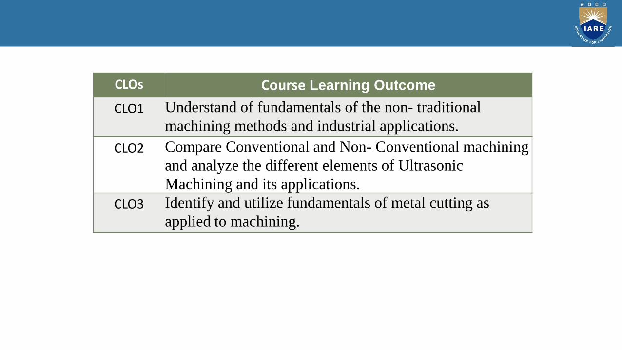
CLOs Course Learning Outcome
CLO1 Understand of fundamentals of the non- traditional
machining methods and industrial applications.
CLO2 Compare Conventional and Non- Conventional machining
and analyze the different elements of Ultrasonic
Machining and its applications.
CLO3 Identify and utilize fundamentals of metal cutting as
applied to machining.

INTRODUCTION
• Traditional machining is mostly based on removal of materials using tools that are
harder than the materials themselves.
• New and novel materials because of their greatly improved chemical, mechanical
and thermal properties are sometimes impossible to machine using traditional
machining processes.
• Traditional machining methods are often ineffective in machining hard materials like
ceramics and composites or machining under very tight tolerances as in
micromachined components.
• The need to a avoid surface damage that often accompanies the stresses created by
conventional machining. Example: aerospace

CLASSIFICATION

CLASSIFICATION
These can be classified according to the source of energy used to generate such a
machining action: mechanical, thermal, chemical and electrochemical.
• Mechanical: erosion of the work material by a high velocity stream of abrasives or fluids
(or both)
• Thermal: the thermal energy is applied to a very small portion of the work surface,
causing that portion to be removed by fusion and/or vaporization of the material. The
thermal energy is generated by conversion of electrical energy.
• Chemical: most materials (metals particularly) are susceptible to chemical attack by
certain acids or other etchants. In chemical machining, chemicals selectively remove
material from portions of work piece.
• Electrochemical: mechanism is reverse of electroplating.

MECHANICAL MACHINING
• Ultrasonic machining (USM) and waterjet machining (WJM) are typical
examples of single action, mechanical non traditional machining
processes.
• The machining medium is solid grains suspended in an abrasive
slurry in the former, while a fluid is employed in the wjm process.
• The introduction of abrasives to the fluid jet enhances the machining efficiency and
is known as abrasive water jet machining. Similar case happens when ice particles
are introduced as in ice jet machining.
HISTORY
• The roots of ultrasonic technology can be traced back to research on thepiezoelectric effect conducted by Pierre Curie around 1880.
• He found that asymmetrical crystals such as quartz and Rochelle salt (potassiumsodium titrate) generate an electric charge when mechanical pressure is applied.
• Conversely, mechanical vibrations are obtained by applying electrical oscillationsto the same crystals.

• One of the first applications for Ultrasonic was sonar (an acronym for
sound navigation ranging). It was employed on a large scale by the U.S.
Navy during World War II to detect enemy submarines.
• Frequency values of up to 1Ghz (1 billion cycles per second) have been
used in the ultrasonic industry.
• Today's Ultrasonic applications include medical imaging (scanning the
unborn fetus) and testing for cracks in airplane construction.

ULTRASONIC WAVES
• The Ultrasonic waves are sound waves of frequency higher than 20,000 Hz.
• Ultrasonic waves can be generated using mechanical, electromagnetic and
thermal energy sources.
• They can be produced in gasses (including air), liquids and solids.

SPECTRUM OF SOUND
Frequency (Hz) Description Example
0-20 Infra sound Earth Quake
20-20000 Audible Sound Speech, Music
> 20,000 Ultrasound Bat, Quartz, Crystal
Sound Spectrum

ULTRASONIC WAVES: PIEZOELECTRIC TRANSDUCERS
• Piezoelectric transducers employ the inverse piezoelectric effect using natural or
synthetic single crystals (such as quartz) or ceramics (such as barium titanate)
which have strong piezoelectric behavior.
• Ceramics have the advantage over crystals in that they are easier to shape by
casting, pressing and extruding.

PRINCIPLE OF ULTRASONIC MACHINING
• In the process of Ultrasonic Machining, material is
removed by micro-chipping or erosion with abrasive
particles.
• In USM process, the tool, made of softer material
than that of the workpiece, is oscillated by the
Booster and Sonotrode at a frequency of about
• 20 kHz with an amplitude of about 25.4 um
(0.001 in).
• The tool forces the abrasive grits, in the gap between
the tool and the workpiece, to impact normally and
successively on the work surface, thereby machining
the work surface.

Ultrasonic Machine setup

Ultrasonic Machine

AIR PLASMA ARC CUTTING SETUP

PRINCIPLE OF ULTRASONIC MACHINING
This is the standard mechanism used in most of the universal Ultrasonic machines

• During one strike, the tool moves down from its most upper remote position with astarting speed at zero, then it speeds up to finally reach the maximum speed at themean position.
• Then the tool slows down its speed and eventually reaches zero again at the lowestposition.
• When the grit size is close to the mean position, the tool hitsthe grit with its full speed.
• The smaller the grit size, the lesser the momentum it receives from the tool.
• Therefore, there is an effective speed zone for the tool and, correspondingly thereis an effective size range for the grits.
PRINCIPLE OF ULTRASONIC MACHINING

PRINCIPLE OF ULTRASONIC MACHINING
• In the machining process, the tool, at some point impacts on the largest grits, which
are forced into the tool and work piece.
• As the tool continues to move downwards, the force acting on these grits increases
rapidly, therefore some of the grits may be fractured.
• As the tool moves further down, more grits with smaller sizes come in contact with
the tool, the force acting on each grit becomes less.
• Eventually, the tool comes to the end of its strike, the number of grits under impact
force from both the tool and the workpiece becomes maximum.
• Grits with size larger than the minimum gap will penetrate into the tool and work
surface to different extents according to their diameters and the hardness of both
surfaces.

VARIOUS WORK SAMPLES MACHINED BY USM
1-The first picture on the left is a plastic sample that has inner grooves that are machined using USM.
2- The Second picture (in the middle is a plastic sample that has complex details on the surface
3- The third picture is a coin with the grooving done by USM

MECHANISM
Piezoelectric Transducer
• Piezoelectric transducers utilize crystals like quartz
• Dimensions alter when being subjected to electrostatic fields.
• The charge is directionally proportional to the applied voltage.
• To obtain high amplitude vibrations the length of the crystal must be
matched to the frequency of the generator which produces resonant
conditions.

Mechanism
PIEZOELECTRIC TRANSDUCER

MECHANISM
• Abrasive Slurry
• The abrasive slurry contains fine abrasive grains. The grains are usually boron carbide,
aluminum oxide, or silicon carbide ranging in grain size from 100 for roughing to 1000
for finishing.
• It is used to microchip or erode the work piece surface and it is also used to carry
debris away from the cutting area.

MECHANISM
• Tool holder
• The shape of the tool holder is cylindrical or
• conical, or a modified cone which helps in magnifying the tool tip vibrations.
• In order to reduce the fatigue failures, it should be free from nicks, scratches
and tool marks and polished smooth.

MECHANISM
• Tool
• Tool material should be tough and ductile. Low carbon steels and stainless steels
give good performance.
• Tools are usually 25 mm long ; its size is equal to the hole size minus twice the
size of abrasives.
• Mass of tool should be minimum possible so that it does not absorb the
ultrasonic energy.

MATERIALS THAT CAN BE USED
• Hard materials like stainless steel, glass, ceramics, carbide, quatz and semi-
conductors are machined by this process.
• It has been efficiently applied to machine glass, ceramics, precision minerals
stones, tungsten.
• Brittle materials

APPLICATIONS
It is used for
• drilling
• grinding,
• Profiling
• coining
• piercing of dies
• welding operations on all materials which can be treated suitably by abrasives.

• 4-axis CNC drills holes as small as 0.010",
multi-sided holes, multiple hole and slot
patterns, and many other complicated,
irregular shapes.
• Works on hard, brittle materials such as
ceramic and glass with precision to
0.0005".
900 watt Ultra Sonic-mill
CNC ULRASONIC MACHINES

LIMITATIONS
• Under ideal conditions, penetration rates of 5 mm/min can be obtained.
• Power units are usually 500-1000 watt output.
• Specific material removal rate on brittle materials is 0.018 mm cubic/Joule.
• Normal hole tolerances are 0.007 mm and a surface finish of 0.02 to 0.7
micro meters.

Advantages of USM
• Machining any materials regardless of their conductivity
• USM apply to machining semi-conductor such as silicon, germanium etc.
• USM is suitable to precise machining brittle material.
• USM does not produce electric, thermal, chemical abnormal surface.
• Can drill circular or non-circular holes in very hard materials
• Less stress because of its non-thermal characteristics

Disadvantages of USM
• USM has low material removal rate.
• Tool wears fast in USM.
• Machining area and depth is restraint in USM.

Safety Considerations
• The worker must be wearing eye goggles to prevent the abrasive particles
or the microchips from getting into his eye.

MODULE–II
ABRASSIVE JET MACHINING
Abrasive jet machining, water jet machining and abrasive water jet machining: basic principles, equipment’s
process variables, mechanics of metal removal, MRR, applications and limitations; Electro chemical processes:
Fundamentals of electro chemical machining, electro chemical grinding, electro chemical honing and deburring
process, metal removal rate in ECM, tool design, surface finish and accuracy, economic aspect of ECM, simple
problem for estimation of metal removal rate

CLOs Course Learning Outcome
CLO4 Understand a problem and apply the fundamentalconcepts and enable to solve problems arising in metalremoval process
CLO5 Explore the ability to define and formulate theproperties of cutting tool materials and characteristics.
CLO5 Illustrate the variables in Abrasive Jet Machining.

ULTRASONIC MACHINING
PRINCIPLE OF USM
It is a machining method, a slurry of particles small abrasive are forced against the work piece by means of a vibrating tool and it causes the removal of metal from the workpiece in the form of extremely small chips.

Ultrasonic machining
• CONSTRUCTION

Ultrasonic machining
• It consists of abrasive slurry, work piece, fixture, table cutting tool, circulating
pump, reservoir, ultrasonic oscillator, leads, excitation coil, feed mechanism,
ultrasonic transducer, transducer cone, connecting body, tool holder
• The ultrasonic oscillator and amplifier also known as generator is used to
convert the applied electrical energy at low frequency to high frequency.
• The transducer is made up of magnetostrictive material and it consists of stack
of nickel laminations that are wound with a coil.
• The function of the transducer is to convert electrical energy to mechanical
energy.
• Tough and ductile tool materials is used in this process. Low carbon steels and
stainless steels are commonly used as tool materials

Ultrasonic Machining
• The tool is generally soldered or fastened mechanically to the
transducer through a metal holder. Generally tool holder is of
• cylindrical or conical in shape.
• The material used for tool holders are titanium alloys, monel aluminium, stainless steel.
• Abrasive slurry usually a mixture of abrasive grains and water of definite propotion ( 20
– 30%) is made to flow under pressure through the gap between the tool and workpiece
of the order of 0.02 to 0.1mm.
• The most commonly used abrasives are boron carbide, silicon carbide, aluminum oxide
and diamond.Boron carbide is most commonly used abrasive slurry since it has the
fastest cutting abrasive property

Ultrasonic machining
• Electric power is given to ultrasonic oscillator and this oscillator converts the electrical
energy of low frequency to high frequency(20kHz)
• This high frequency from oscillator is supplied to transducer.
• The transducer converts the electrical energy to mechanical vibrations. The transducer is
made up of magnetostrictive material, which is excited by flowing high frequency electric
current and this results in the generation of mechanical vibrations.
• The vibrations generated in the transducer is of the order of 20kHz to 30kHz and hence
ultrasonic waves are produced.
• The vibrations are then transmitted to the cutting tool through transducer cone,
connecting body and tool holder. This makes the tool to vibrate in a longitudinal
direction.

Ultrasonic machining
• Abrasive slurry is pumped from the reservoir and it is made to flow under
pressure through the gap between tool and workpiece.
• In an abrasive slurry when the cutting tool vibrates at high frequency it leads
to the removal of metal from the workpiece.
• The impact force arises from the vibration of the tool end and the flow of
slurry through the workpiece & tool gap causes thousands of microscopic
grains to remove the workpiece material by abrasion.
• A refrigerated cooling system is used to cool the abrasive slurry to a
temperature of 5 to 60C.
• The ultrasonic machining process is a copying process in which the shape of
the cutting tool is same as that of the cavity produced

Transducers
• Transducer : It is a device which converts one form of energy into another
form of energy. In ultrasonic machining process it converts the electrical
energy into mechanical energy.
• Types of transducers:
• Magnetostriction transducer
• Piezoelectric transducer

• Principle :
• When a rod of ferromagnetic material such as iron or nickel is kept in a
magnetic field parallel to its length the rod suffers a change in its length.
• The change in length is independent of the direction of the magnetic field and
depends only on the magnitude of the field and nature of the material. This
phenomenon is known as magnetostriction effect
Magnetostriction Transducer
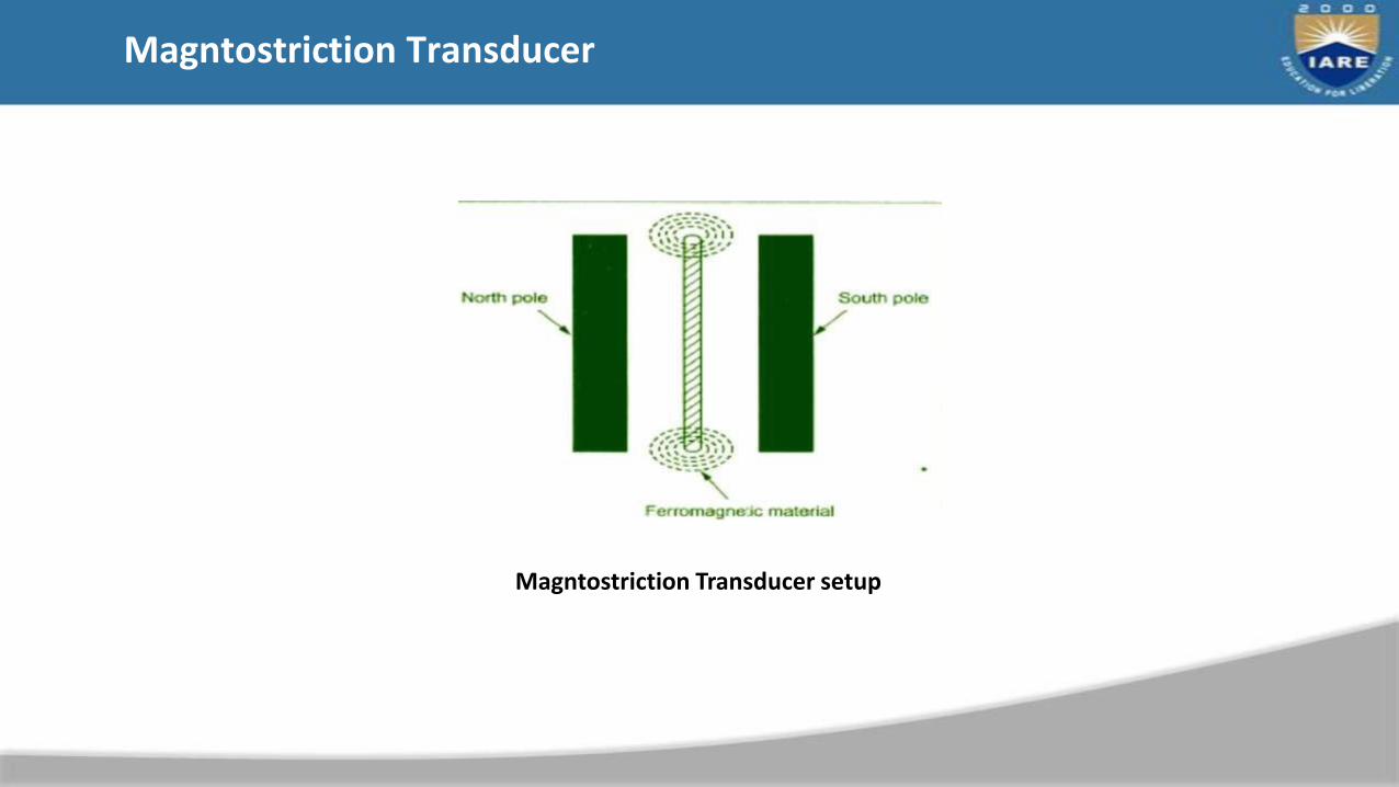
Magntostriction Transducer
Magntostriction Transducer setup

Magneto striction Transducer
• Construction

• A rod of (AB) ferromagnetic material iron or nickel is clamped at the middle.
• The two ends A and B of the rod is wound by the coil L1 and L2.
• The coil L1 wound on the right hand portion of the rod along with a variable
capacitor C1. The coil L2 wound on the left hand portion of the rod is
connected to the grid circuit.
• The frequency of the oscillatory circuit is adjusted by the variable capacitor C1
and the current is noted by the milliammeter.
• The LT battery and HT battery are provided to produce current in the grid
circuit
Magnetostriction Transducer

MAGNETOSTRICTION TRANSDUCER
• Working :
• The filament in the grid circuit is heated by the low tension battery. This
causes the production of electrons and these electrons are accelerated by
using high tension battery.
• So current is produced in the circuit.
• The Alternating current passes through the coil L1 which produces an
alternating magnetic field along the length of the rod.
• The result is the rod vibrated due to the magnetostriction effect. The
vibrations of the rod create ultrasonic waves which are sent out.

MAGNETOSTRICTION TRANSDUCER
• The longitudinal expansion and contraction of the rod (AB) produces an emf in
the coil L2. This induced emf is fed due to the grid circuit continuously as a
feed back.
• In this way the current is built up and the vibrations of the rod is maintained.

MAGNETOSTRICTION TRANSDUCER
• When the frequency of the oscillatory circuit is equal to the frequency of the
vibrating rod the resonance occurs.
• At resonance the rod vibrates vigorously and ultrasonic waves are
produced with high frequencies.

MAGNETOSTRICTION TRANSDUCER
Advantages :
• Production cost is low
• Very simple design .At low ultrasonic frequencies large power output is possible
• without any damage to the oscillatory circuit.
Limitations :
• It cannot produce ultrasonic waves of frequency above 3000 kHz.
• The frequency of oscillations depends on temperature.
• Losses of energy due to hysteresis and eddy current
• As the frequency is inversely proportional to length of the rod the length of
the rod should be decreased to increase the frequency.

PIEZOELECTRIC TRANSDUCER
• Piezoelectric effect :
• When mechanical force is applied to one pair of opposite faces of certain
crystals like quartz, tourmaline equal and opposite electrical charges appear
across its other faces. But ultrasonic waves are generated based on Inverse
piezoelectric effect
• Inverse piezoelectric effect :
• When an a.c. voltage is applied across the piezoelectric crystal it starts
vibrating at the frequency of the applied voltage

PIEZOELECTRIC TRANSDUCER
Construction :

PIEZOELECTRIC TRANSDUCER
• It consists of a primary and secondary circuit. The primary circuit is arranged
with coils L1 & L2.
• Coil L1 is connected to the grid circuit and the coil L2 is connected to the plate
circuit.
• The frequency of the oscillatory circuit is varied by using the capacitor C1.
• The quartz crystal is placed between two metal plates A and B. The plates are
connected to the secondary coil L3 of the transformer

PIEOELECTRIC TRANSDUCER
• Working :
• The filament in the grid circuit is heated by the low tension battery (LT). This
causes the production of electrons and these electrons are accelerated with a
very high velocity by high tension battery (HT)
• So alternating current is produced in the circuit.
• This alternating current is passed through the coil L1 and L2 of the primary
circuit
• and it is transferred to the secondary circuit L3.
• At resonance the crystal vibrates vigorously and ultrasonic waves are produced
with very high frequencies.

PIEOELECTRIC TRANSDUCER
• This current is passed to the plates A and B and it leads the crystal to vibrate
due to the principle of inverse piezo electric effect. The vibrations of the
crystal will create ultrasonic waves.
• When the frequency of the oscillatory circuit is equal to the frequency of the
vibrating crystal resonance occurs.

PIEZOELECTRIC TRANSDUCER
Advantages :
• It is more efficient than magnenostriction transducer
• It can produce frequency upto 500 MHz.
• It is not affected by temperature and humidity.
Disadvantages:
• The cost of piezoelectric quartz is high
• Cutting and shaping of quartz crystal is very complex

FEED MECHANISM
• Feed system is used to apply the static load between the tool and workpiece during
ultrasonic machining process
• The basic requirements to tool mechanism are as follows
1. The tool should be moved slowly to prevent breaking
2.The tool has to come back to its initial position after finishing its machining
operation.
• There are three types of feed mechanism. They are
1. Gravity feed mechanism
2. Spring loaded feed mechanism
3. Pneumatic (or) Hydraulic feed mechanism

FEED MECHANISM
• Gravity feed mechanism

• In this mechanism counter weights are used to apply the load to the headthrough the pulley.
• The overall impact force is the difference between the weight of the acoustichead and that of the counter weight used.
• The force here can be adjusted by varying the counter weights
• In order to reduce the friction the ball bearings are used.
• Gravity feed mechanism is generally preferred because of simple construction

SPRING LOADED FEED MECHANISM

• In this mechanism the spring pressure is used to feed the tool during the
machining operation.
• This mechanism is also preferred because of its sensitivity and compactness.
SPRING LOADED FEED MECHANISM:
• In order to get high feed rate, pneumatic feed mechanism is used

PNEUMATIC OR HYDRAULIC FEED MECHANISM
Pneumatic or Hydraulic feed mechanism

In usm the metal removal rate depends on the following
(a) Grain size of the abrasive
(b) Abrasive materials
(c) Concentration of slurry
(d) Amplitude of vibration
(e) Frequency of Ultrasonic waves
METAL REMOVAL RATE

METAL REMOVAL RATE
(a) Grain size of the abrasive
• MRR and surface finish are greatly influenced by the grain size of the abrasive
• Maximum rate in machining isattainedwhen the grain size of the abrasive is bigger.
• For rough work operation grit size of 200-400 is used and for finishing operation the grit size of 800-1000 is used Grain size vs MRR

METAL REMOVALRATE
(b) Abrasive Materials
• The proper selection of the abrasive particles depends on the type of materialto be machined, hardness of the material and metal removal rate and thesurface finish required.
• The most commonly used abrasive materials are boron carbide and siliconcarbide used for machining tungsten carbide and die steel.
• Aluminum oxide is the softest abrasive used for machining glass and ceramics

METAL REMOVAL RATE
(c) Concentration of slurry:
• Abrasive slurry usually a mixture of abrasive
grains and water of definite proportion 20-30% is made to flow flow under pressure.
• The figure shows how the metal removal ratevaries with slurry concentration
Abrasive concentration vs MRR

METAL REMOVAL RATE
(d) Amplitude of Vibration
• Metal removal rate in ultrasonic machining process increases with increasing amplitude of vibration
Amplitude vs MRR

METAL REMOVAL RATE
(e) Frequency
Ultrasonic wave frequency is directly proportional to the metal removal rate as shown in the fig.

PROCESS PARAMETERS
• The various process parameters involved in USM methods are as
follows
• (a)Metal removal rate (b)Tool Material
• Tool Wear rate
• Abrasive materials and abrasive slurry (e)Surface finish
• (f) Work Material

PROCESS PARAMETERS
• Tool material
• Low carbon steel and stainless steel are most commonly used
tool materials.
• Since long length tools cause overstress the tool should be
short and rigid.
• Hollow tool can be made with wall thickness greater than 0.5 to 0.8 mm
• Side Clearance is of the order of 0.06mm to 0.36 mm

PROCESS PARAMETERS
• Tool wear ratio
• It is defined as the ratio of the volume of the material removed from the work
to the volume of material removed from the tool
• 1.5:1 for tungsten carbide work piece 100:1 for glass
• 50: 1 for quartz
• 75:1 for ceramics
• 1:1 for hardened tool steel

PROCESS PARAMETERS
• Surface Finish
• The maximum speed of penetration in soft and brittle materials such as soft
ceramics are of the order of 200mm/min.
• Penetration rate is lower for hard and tough materials.
• Accuracy of this process is ± 0.006mm
• Surface finish upto 0.02 to 0.8 micron value can be achieved

PROCESS PARAMETERS
• Work Materials
• Hard and Brittle materials, non metals like glass, ceramics etc and
semiconductors are used as work material in usm process.
• Wear ratio, average penetration rate, maximummachining area of the
different workpiece materials are shown in the table

PROCESS PARAMETERS
• Work Materials
• Hard and Brittle materials, non metals like glass, ceramics etc and
Semiconductors are used as work material in usm process.
• Wear ratio, average penetration rate, maximummachining area of the
different workpiece materials are shown in the table

ADVANTAGES OF USM
• Extremely hard and brittle materials can be easily machined
• Cost of metal removal is low
• Noiseless operation
• High accuracy and surface finish can be easily obtained
• No heat generation in this process. So the physical properties of the work
piecematerial remain unchanged
• Equipment is safe to operate
• Nonconducting materials such as glass, ceramics andsemi
precision stones can be easily machined.
• The machined workpieces are free from stress

DISDAVANTAGES
• Wear rate of the tool is high
• The initial cost of equipment is high
• For effective machining the abrasive materials should be replaced periodically
since the dull abrasives stop cutting action
• High power consumption
• Tool cost is high
• The size of the cavity that can be machined is limited

APPLICATIONS & LIMITATINS OF USM
• Applications :
• Holes as small as 0.1mm can be drilled
• Precise and intricate shaped articles can be machined
• It has been efficiently applied to machine glass, ceramics, tungsten, precision
mineral stones.
• Used for making tungsten carbide and diamond wire drawing dies and dies for forging
and extrusion process
• Machining operations like drilling, turning, threading, cutting, grinding, profiling on
all materials both conducting and non conducting materials.
• Limitations:
• Under Ideal conditions :

CHARACTERISTICS OF USM
• Metal removal mechanism : Slurry of small abrasive particles are forced
• against the workpiece by means of vibrating tool and it causes the removal of metal
from the workpiece
• Abrasive : Silicon carbide, boron carbide, aluminum oxide and diamond
• Abrasive slurry : abrasive grains + 20-30% water
• Vibration frequency : 20 to 30 kHz, Amplitude : 25 – 100m
• Wear ratio:1.5:1 for tungsten carbide work piece, 100:1 for glass,
• 50: 1 for quartz, 75:1 for ceramics ,1:1 for hardened tool steel
• Work Material : Tungsten carbide, germanium, glass, ceramics, quartz, tool steel
• Toolmaterial : Low carbon steel, stainless steel
• Surface finish : 0.2 to 0.7 µ

ABRASIVE WATER JET MACHINING (AWJM)

Electrical Energy Based Removing Techniques
• Electrochemical grinding (ECG)
• Electrochemical Honing
• Electrochemical machining (ECM)
4/21/2017

Electrochemical grinding overview
• Electrochemical grinding is a variation of ECM that combines electrolytic activity
with the physical removal of material by means of electrically charged wheels
• ECG can produce burr free and stress free parts without heat or metallurgical
caused by mechanical grinding , eliminating the need for secondary machining
operations
• Like ECM, (ECG) generates little or no heat that can distort delicate components

DEFINITION of ECG
• Electrochemical grinding is a special from of electrochemical machining, which employs
the combined actions of electrochemical attack and abrasion to rapidly remove material
from electrically conductive work pieces, usually hard, tough materials.
• It is a non-abrasive process and, therefore, produce precise cuts
• that are free of heat, stress, burrs and mechanical distortions.
• It is a variation on electrochemical machining that uses a
• conductive, rotating abrasive wheel.
• ECG can be compared to electroplating, but with major differences, ECG deplates
material from the work and deposits it in the electrolyte; however, it does not plate
material from the work onto the wheel.

Fig: SCHEMATIC VIEW OFECG

Fig : THREE PHASES OF ECG MATERIAL REMOVAL

PROCESS CHARACTERISTICS
• The wheels and work piece are electrically conductive
• Wheels used last for many grindings - typically 90% of the metal are removed by
electrolysis and 10% from the abrasive grinding wheel
• Capable of producing smooth edges without the burrs caused by
• mechanical grinding
• Does not produce appreciable heat that would distort work piece.
• Decomposes the work piece and deposits them into the electrolyte
• solution. The most common electrolytes are sodium chloride
• and sodium nitrate at concentrations of 2 lbs per gallon

Machining Conditions in ECG
• Feed rate • 0.25 mm/min
• Gap • 0.025 mm
• Grinding wheel surface speed • 25 – 30 m/s
• Voltage • 5-15 V DC for steel
• 6 -10 V DC for WC work material
• Current density • 50 – 200 A/cm2
• Metal removal rate • 100 – 500 mm3 /mincm2 on steel W/P
• 50 – 200 mm3/mincm2 on tungsten carbide work piece
• Contact pressure of W/P
against the wheel
• Varies from 1 to 8 kg/cm2
• Electrolyte • Water mixed with NaCl,NaNO3 and NaNO2

• Accuracy obtainable • 0.010 mm
• Surface finish • 0.1 -0.2 finishes are possible
• Power of motor driving the
spindle
• 1 HP
• Power of motor driving the
electrolyte pump
• 0.5 HP
• Operating current range • 150 – 300 amperes
• Rating of power pack • 3.5 kVA

Typical surface roughness Data for Electrochemical metal removal process
• Electro – Chemical Metal
Removal Process
• Surface Roughness Values (RMS)
• Range (microns) • Average Values
• ECM • 0.1 -4.0 • 0.25 – 1.0
• ECG • 0.1 -1.0 • 0.10 – 0.5
• ELP • 0.1 – 1.0 • 0.10 – 0.5

METAL REMOVAL RATE IN ECG
• In ECG, the total metal removed is the sum of metal removal obtained by
electrochemical action and by mechanical grinding action
• Total metal removed , Vt = Ve + Vg
• Ve = volume of metal removed by electrochemical action Vg = volume of metal
removed by Grinding action due to fast rotation of the abrasive wheel

TOLERANCE
• The tolerances that can be achieved using ELECTROCHEMICAL GRINDING (ECG)
depend greatly on the material being cut, the size and depth of cut and ECG
parameters being used.
• On small cuts, tolerances of .0002” (.005mm) can be achieved with
• careful control of the grinding parameters.
• This kind of grinding is mostly used because it can shape very hard metals and
also because it is a chemical reducing process, the wheel lasts a longer time than
normal grinding wheel can.
• This type of grinding has different types of wheels so it can shape metals to
whatever they need to be shaped to.
• Produces a smoother, burr-free surface and causes less surface stress than other
grinding methods

IMPORTANT POINTS TO BE OBSERVED THE ECG PROCESS FOR SUCCESSFUL RESULTS
• ECG equipment must be in good condition to achieve best results in electrolytic
grinding
• The carbide work piece should not be allowed to dwell against the wheel as this
will result in pitting
• The diamond wheel must be kept clean in order to maintain the proper gap
between the anode and the cathode. A soft dressing stick ( aluminum oxide ) may
be used for this purpose
• HSS is generally machined with high current density whereas WC is generally
machined with low current density

CONTROL OF OVERCUT IN ECG
• Machining parameters which affect overcut in electrolytic grinding include
the following
• Voltage (overcut is directly proportional)
• Current density
• Electrolyte (overcut is directly related)
• Feed rate (overcut is inversely proportional) and
• Work piece composition

PERFORMANCE CHARACTERISTICS OF ECG PROCESS
• Influence of contact pressure
• Influence of grinding wheel speed
• Influence of the D.C potential between wheel and the work piece
• Influence of Abrasive Grain Size

Influence of contact pressure
• Increase in the contact pressure results in higher electrochemical metal
removal rate as well as higher mechanical metal removal rate
Contact pressure, kg/cm2
Q,mm3/min
Influence of contact pressure on MRR
Q,mm3/min
Contact pressure, kg/cm2

INFLUENCE OF GRINDING WHEEL SPEED
• As grinding wheel speed is increased , metal removal rate as well
• as current density increases.
• Higher grinding wheel speeds also increase the flow of electrolyte
and thus decreasing the effect of heat and gas formation
Diamond wheel speed
Q,mm3/min
Diamond wheel speed
J,A/cm2
Influence of grinding wheel speed

INFLUENCE OF D.C POTENTIAL BETWEEN WHEEL AND WORK PIECE
Contact pressure ,kg/cm2
Q,mm3/ min
Contact pressure ,kg/cm2
J,A/cm2
D 100
D 200
D 50

• Diamond wheels. These wheels are used to electrochemically grind flat surfaces of
tungsten carbide tools and other carbide parts.
• Nondiamond-face wheels. This type of wheel is used for grinding the flat surfaces of
steels and alloy steels. The abrasive used in this type of wheelhas been aluminum
oxide.
• Nondiamond wheels. Dress able resin-bond and copper- loaded wheels
(Copperdyne) are used extensively for all applications other than tungsten carbide
WHEELS FOR ECG

DIAMOND WHEEL SPECIFICATION
Shape of Wheel Cup –type Wheel
Bond used Metallic bond (bronze)
Diameter of wheel 250 mm
Width of the rim 20 -25 mm
Diamond concentrationused
D100
Mesh no: of diamond particles used
100 to 200
Wheel speed used 1800 m/min
Grinding ratio 80

• During ECG, the abrasive wheel functions as follows:
• The abrasive in the wheel continuously removes an electrically resistant film from the
face of the work. If this dielectric film were allowed to remain, the flow of direct
current would stop and there would be no electrochemical action.
• The abrasive provides an electrically insulated gap between the
• cathodic wheel and the anodic work. Without this there would be a direct electrical
short and resultant damage to both the wheel and the work. For optimum or
maximum stock removal, the gap must be less than 0.03 mm.
• The wheel carries the electrolyte in the spaces between the abrasive grains across the
face of the work. Without the electrolyte between the wheel and the work, there
would be no electrochemical action.
FUNCTIONS OF ABRASIVE WHEEL

• Material and its alloys • Electrolyte used
• Ferrous, Nickel, and Cobalt alloys • Sodium chloride
• Tungsten carbide • Sodium nitrate as the active ingredient, with
rust inhibitor and chelating-agent additives.
• Titanium, Zirconium, and Columbium. • Sodium chloride
• Tungsten and Molybdenum • Sodium carbonate-sodium
• hydroxide
• Copper or Silver • Sodium Nitrite.
ELECTROLYTES FOR ECG
• Electrolytes are formulated at about 120-240 g/L. Temperature of the electrolyte is
maintained between 30-45 ° C; pressure used to pump the fluid is about 35-70 KPa.
Filtration of the electrolyte is important; filtration to 50-100 m is sufficient.

ADVANTAGES
• ECG increases wheel life due to negligible wear
• Fixtures used for holding the components are simple in construction
• Cutting tools with specially shaped tips can be ground quickly
• No overheating occurs and henceno surface cracks are produced on parts
machined by ECG
• A surface finish up to 0.25 micron is possible
• No metallurgical damage from heat
• Cost of grinding is reduced by 25 – 40%
• More precise tolerances can be obtained

DISADVANTAGES
• High capital cost
• Corrosive environment
• High preventive maintenance costs
• Not economical for soft materials
• Machining of cast iron by ECG present certain difficulties
• Non conducting hard work materials such as ceramics cannot be machined by
ECG process

APPLICATIONS
• Primarily used in the grinding of Tungsten carbide tool bits
• Grinding of cutting tools, chilled iron castings , magnet alloys, contour milling
of honey- comb structures
• Used for machining of cemented carbides , stellites, refractory materials,
stainless steel and high alloys steels without any burr
• Chromium plated materials, flame hardened materials and
• temperature sensitive alloys can be machined without forming thermal cracks
and distortion
• Grinding of super alloy turbine blades
• Burr free sharpening of hypodermic needles

ELECTROCHEMICAL HONING
• Electrochemical Honing (ECH) is a hybrid process in which material removal occurs
by electrochemical dissolution as well as honing (by shearing action) simultaneously.
• Material removal alternatively takes place by honing and by electrolytic dissolution
(see electrochemical grinding).
• bonding material of the honing stone should be electrically conducting. However,
conventional honing stones made of electrically non-conducting bonding material
can also be used and the current is passed to the work piece via electrodes mounted
• between the honing stones.
• Electrodes are fitted with spacers such that a gap (0.075-0.125 mm) is maintained
between the electrodes and the work

Fig : ELECTROCHEMICAL HONING

Advantages
• High MRR
• free burr surfaces
• reduced noise
• Increased accuracy
• Reduced work damage

MODULE–III
THERMAL METAL REMOVAL PROCESSES
General principle and applications of Electric discharge machining, electric discharge grinding, electric discharge wire
cutting processes, power circuits in EDM, mechanism of metal removal in EDM, process parameters.
Selection of tool electrodes and dielectric fluids, surface finish and accuracy, characteristics of spark eroded surface
and machine tool selection, wire EDM principle and applications.

CLOs Course Learning Outcome
CLO7 Explain the different elements of Chemical and Electrochemical Machining and its applications.
CLO8 Comparison between non-traditional machiningprocess with the traditional parameters, energysources, economics of processes, shape and size of thematerial.
CLO9 Illustrate different parameters of Electrical DischargeMachining.

INTRODUCTION
Strength temperature resistant alloys.
• Electro Discharge Machining (EDM) is an electro-thermal non- traditional
machining process, where electrical energy is used to generate electrical
spark and material removal mainly occurs due to thermal energy of the
spark.
• EDM is mainly used to machine difficult-to-machine materials and highstrength temperature resistant alloys.
• EDM can be used to machine difficult geometries in small batches or even
on job-shop basis.2

MAJOR COMPONENTS OF EDM
The main components of EDM are
• Electric power supply
• Work piece & tool
• Dielectric medium
• Servo control unit.
3

Electro Discharge machine setup

WORKING
• In EDM, a potential difference is applied between the tool and work
piece.
• Both the tool and the work material are to be conductors of electricity.
• The tool and the work material are immersed in a dielectric medium.
• Dielectric Medium-kerosene or deionised water.
• Gap is maintained between the tool and the work piece.
• Depending upon the applied potential difference and the gap between
the tool and work piece, an electric field would be established.
4

• Tool is connected to the negative terminal of the generator and the work piece is
connected to positive terminal.
• As the electric field is established between the tool and the job, the free electrons
on the tool are subjected to electrostatic forces
• “cold emission”- the work function or the bonding energy of the electrons is less,
electrons would be emitted from the tool (assuming it to be connected to the
negative terminal).
• Such emission of electrons are called or termed as cold emission.

WORKING
Schematic representation of the basic working principle of EDM process.
6

• The “cold emitted” electrons are then accelerated towards the job through the dielectric
medium, as they gain velocity and energy, and start moving towards the job, there
would be collisions between the electrons and dielectric molecules. Such collision may
result in ionization of the dielectric molecule.
• As the electrons get accelerated, more positive ions and electrons would get generated
due to collisions.
• This cyclic process would increase the concentration of electrons and ions in the
dielectric medium between the tool and the job at the spark gap.

• The concentration would be so high that the matter existing in that
channel could be characterized as “plasma”.
EDM

WORKING (CONT..,)
• The electrical resistance of such plasma channel would be very less.
• Thus all of a sudden, a large number of electrons will flow from
• tool to job and ions from job to tool.
• This is called avalanche motion of electrons.
• Such movement of electrons and ions can be visually seen as a spark.
• Thus the electrical energy is dissipated as the thermal energy of the spark.
• The high speed electrons then impinge on the job and ions on the tool.
• The kinetic energy of the electrons and ions on impact with the surface of the job and
tool respectively would be converted into thermal energy or heat flux.

WORKING
• Such intense localized heat flux leads to extreme instantaneous confined rise in
temperature which would be in excess of 10,000oC.
• Such localized extreme rise in temperature leads to material removal.
• Material removal occurs due to instant vaporization of the material as
• well as due to melting.
• The molten metal is not removed completely but only partially.
• As the potential difference is withdrawn, the plasma channel is no longer sustained. As
the plasma channel collapse, it generates pressure or shock waves, which evacuates the
molten material forming a crater of removed material around the site of the spark.

WORKING
• Upon withdrawal of potential difference, plasma channel collapses.
• This ultimately creates compression shock waves on the electrode surface.
• Particularly at high spots on work piece surface, which are closest to the
• tool.
• This evacuates molten material and forms a crater around the site of the
spark.
• The whole sequence of operation occurs within a few microseconds.

SUMMARY
• The material removal in EDM mainly occurs due to formation of shock waves
• as the plasma channel collapse owing to discontinuation of applied potential difference
• Generally the work piece is made positive and the tool negative.
• Hence, the electrons strike the job leading to crater formation due to high temperature
and melting and material removal.
• Similarly, the positive ions impinge on the tool leading to tool wear.
• The generator is used to apply voltage pulses between the tool and job.
• A constant voltage is not applied. Only sparking is desired rather than arcing.
• Arcing leads to localized material removal at a particular point whereas sparks get
distributed all over the tool surface leading to uniform material removal.

ELECTRODE
• Electrode material should be such that it would not undergo much tool wear it is
impinged by positive ions.
• Thus the localized temperature rise has to be less by properly choosing its
properties or even when temperature increases, there would be less melting.
• High electrical conductivity – electrons are cold emitted more easily and there is
less bulk electrical heating
• High thermal conductivity – for the same heat load, the local temperature rise
would be less due to faster heat conducted to the bulk of the tool and thus less tool
wear

• Higher density – for the same heat load and same tool wear by weight there would
be less volume removal or tool wear and thus less dimensional loss or inaccuracy .
• High melting point – high melting point leads to less tool wear due to less tool
material melting for the same heat load
• Easy manufacturability
• Cost – cheap
• Recommended Electrode materials:
• Graphite
• Electrolytic oxygen free copper
• Tellurium copper – 99% Cu + 0.5% tellurium

DIELECTRIC
• Material removal mainly occurs due to thermal evaporation and melting.
• As thermal processing is required to be carried out in absence of oxygen so that the
process can be controlled and oxidation avoided.
• Oxidation often leads to poor surface conductivity (electrical) of the workpiece
hindering further machining .
• Dielectric fluid should provide an oxygen free machining environment.
• Further it should have enough strong dielectric resistance so that it does not breakdown
electrically too easily.
• But at the same time, it should ionize when electrons collide with its molecule.
• Moreover, during sparking it should be thermally resistant as well.
• Generally kerosene and deionised water is used as dielectric fluid in EDM.

DIELECTRIC
• Tap water cannot be used as it ionizes too early and thus breakdown due to presence
of salts as impurities occur.
• Dielectric medium is generally flushed around the spark zone.
• It is also applied through the tool to achieve efficient removal of molten material.
• Three important functions of a dielectric medium in EDM:
• Insulates the gap between the tool and work, thus preventing a spark to form until the
gap voltage are correct.
• Cools the electrode, work piece and solidifies the molten metal particles.
• Flushes the metal particles out of the working gap to maintain ideal cutting conditions,
increase metal removal rate.

DIELECTRIC
• It must be filtered and circulated at constant pressure
• The main properties of the EDM dielectric fluids are adequate viscosity,
high flash point, good oxidation stability, minimum odor, low cost, and
good electrical discharge efficiency.
• For most EDM operations kerosene is used with certain additives that
• prevent gas bubbles and de-odoring.
• Silicon fluids and a mixture of these fluids with petroleum oils have
given excellent results.
• Other dielectric fluids with a varying degree of success include aqueous
solutions of ethylene glycol, water in emulsions, and distilled water.

POWER GENERATOR
Different power generators are used in EDM and some are listed below
• Resistance-capacitance type (RC type) Relaxation generator
• Rotary impulse type generator
• Electronic pulse generator
• Hybrid EDM generator

RESISTANCE-CAPACITIVE (RC) TYPE RELAXATION GENERATOR
Relaxation Generator

RC TYPE RELAXATION GENERATOR
• The capacitor is charged from a DC source.
• As long as the voltage in the capacitor is not reaching the breakdown
voltage of the dielectric medium under the prevailing machining
condition, capacitor would continue to charge.
• Once the breakdown voltage is reached the capacitor would start
discharging and a spark would be established between the tool and
workpiece leading to machining.
• Such discharging would continue as long as the spark can be sustained.
Once the voltage becomes too low to sustain the spark, the charging of
the capacitor would continue.

• For maximum power dissipation in RC type EDM generator Vc* = 0.716Vo.
• The discharging time or machining time or on time can be expressed as

∴ Frequency of operation,
Total energy discharged through spark gap

Rotary impulse generator with rectifier
Electronic Pulse Generator
Hybrid Electronic Pulse Generator

PROCESS PARAMETERS

The waveform is characterized by the following
• The open circuit voltage - Vo
• The working voltage - Vw
• The maximum current - Io
• The pulse on time – the duration for which the voltage pulse is applied - ton
• The pulse off time - toff
• The gap between the workpiece and the tool – spark gap - δ
• The polarity – straight polarity – tool (-ve)
• The dielectric medium
• External flushing through the spark gap.

EDM – MATERIAL REMOVAL RATE

• material removal in a single spark can be expressed as
• the energy content of a single spark can be expressed is
PROCESS PARAMETERS
• Material removal rate:
Tool
Spark
Crater

PROCESS PARAMETERS
Taper cut & over cut Prevention of Taper Cut
Insulated

EDM – CHARACTERISTICS
• Can be used to machine any work material if it is electrically conductive.
• Capacitor discharge is between 50 and 380 V
• Dielectric slurry is forced through this gap at a pressure of 2 kgf/cm2 or lesser.
• A gap, known as SPARK GAP in the range, from 0.005 mm to 0.05 mm is maintained
between the work piece and the tool.
• The current density in the discharge of the channel is of the order of 10000 A/cm2 and
power density is nearly 500 MW/cm2.
• MRR depends on thermal properties (job) rather than its strength, hardness etc.
• The volume of the material removed per spark discharge is typically in the range of
(1/1,000,000) to (1/10,000) mm3.

EDM – CHARACTERISTICS
• In EDM, geometry oftool – positive impression of hole or geometric feature.
• Tool wear once again depends on the thermal properties of tool material.
• Local temperature rise is rather high, but there is not enough heat diffusion (very
small pulse on time) and thus HAZ is limited to 2 – 4 μm.
• Rapid heating and cooling leads to surface hardening which may be desirable in
some applications.
• Tolerance value of + 0.05 mm could be easily achieved by EDM.
• Best surface finish that can be economically achieved on steel is 0.40 m31

APPLICATIONS
• Drilling of micro-holes, thread cutting, helical profile milling,
• rotary forming, and curved hole drilling.
• Delicate work piece like copper parts can be produced by EDM.
• Can be applied to all electrically conducting metals and alloys irrespective of their
melting points, hardness, toughness, or brittleness.
• Other applications: deep, small-dia holes using tungsten wire as tool, narrow slots,
cooling holes in super alloy turbine blades, and various intricate shapes.
• EDM can be economically employed for extremely hardened work piece.
• Since there is no mechanical stress present (no physical contact), fragile and slender
work places can be machined without distortion.
• Hard and corrosion resistant surfaces, essentially needed for die making, can be
developed

ADVANTAGES
• Some of the advantages of EDM include machining of:
• Complex shapes that would otherwise be difficult to produce with
conventional cutting tools.
• Extremely hard material to very close tolerances.
• Very small work pieces where conventional cutting tools may
• damage the part from excess cutting tool pressure.
• There is no direct contact between tool and work piece. Therefore
delicate sections and weak materials can be machined without any
distortion.
• A good surface finish can be obtained.

DISADVANTAGES
Some of the disadvantages of EDM include:
• The slow rate of material removal.
• For economic production, the surface finish specified should not be too fine.
• The additional time and cost used for creating electrodes for ram/sinker EDM.
• Reproducing sharp corners on the workpiece is difficult due to electrode wear.
• Power consumption is high.
• "Overcut" is formed.
• Excessive tool wear occurs during machining.
• Electrically non-conductive materials can be machined only with specific set-up of the
process
PRINCIPLE OF EDM
• Controlled metal-removal technique where electric spark used to cut (erode)
workpiece.
• Takes shape opposite to that of cutting tool
• Electrode (cutting tool) made from electrically conductive material
• Dielectric fluid surrounds both tool and work
• Servo mechanism gives gap .005 to .001 in. between work and tool
• Direct current of low voltage.

WIRE-CUT EDM MACHINE
• Uses thin brass or copper wire as electrode.
• Makes possible cutting most shapes and contours from flat plate materials
• Complex shapes: tapers, involutes, parabolas and ellipses
• Process commonly used for: Machining, tungsten, carbide, diamond,
polycrystalline, nitride, pure molybdenum, difficult-to-machine material


PROCESS OF WIRE CUT EDM
• Uses CNC to move workpiece along X and Y axes in horizontal plane toward
vertically moving wire electrode
• Electrode does not contact workpiece but operates in stream of dielectric
fluid
• Directed to spark area between work and electrode
• When in operation, dielectric fluid in spark area breaks down, forming gas
that permits spark to jump between workpiece and electrode
• Eroded material caused by spark washed away

OPERATING SYSTEMS
• Four main operating systems of wire-cut electrical discharge machines
• Servo mechanism
• Dielectric fluid
• Electrode
• Machine control unit

SERVO MECHANISM
• Controls cutting current levels, feed rate of drive motors, and traveling speed of wire
• Automatically maintains constant gap of .001 to .002 in. between wire and workpiece
• Important there be no physical contact
• Advances workpiece into wire, senses work-wire spacing, and slows or speeds up drive
motors to maintain proper arc gap

DIELECTRIC FLUID
• Usually deionized water Serves several functions:
• Helps initiate spark between wire and work
• Serves as insulator between wire and work
• Flushes away particles of disintegrated wire and work from gap to prevent
shorting
• Acts as coolant for both wire and workpiece

ELECTRODE
• Spool of brass, copper, tungsten, molybdenum, or zinc wire ranging from
.002 to .012 in. in diameter (2 to 100 lb)
• Continuously travels from supply spool to takeup spool so new wire always
in spark area
• Both electrode wear and material-removal rate from workpiece depend on:
• Material's electrical and thermal conductivity, its melting point and duration
and intensity of electrical pulses

CHARACTERISTICS OF ELECTRODE MATERIALS
• Be good conductor of electricity
• Have high melting point
• Have high tensile strength
• Have good thermal conductivity
• Produce efficient metal removal from workpiece

ADVANTAGES OF EDM
• Process is burr-free.
• Thin, fragile sections easily machined without deforming.
• Process is automatic – servo mechanism advances electrode into work
as metal removed.
• One person can operate several EDM machines at one time.
• Better dies and molds can be produced at lower cost.
• A die punch can be used as electrode to reproduce its shape in
matching die plate, complete with necessary clearance.

LIMITATIONS OF EDM
• Metal-removal rates are low
• Material to be machined must be electrically conductive
• Rapid electrode wear can become costly
• Electrodes smaller than 0.003 inches in diameter are impractical

INTRODUCTION
• Electro Discharge Machining (EDM) is an electro-thermal non- traditional
machining process, where electrical energy is used to generate electrical spark and
material removal mainly occurs due to thermal energy of the spark.
• EDM is mainly used to machine difficult-to-machine materials and high
• strength temperature resistant alloys.
• EDM can be used to machine difficult geometries in small batches or even on job-
shop basis.
• Work material to be machined by EDM has to be electrically conductive.

MAJOR COMPONENTS OF EDM
The main components of EDM are
• Electric power supply
• Work piece & tool
• Dielectric medium
• Servo control unit.

MAJOR COMPONENTS OF EDM
Electro Discharge Machine setup

WORKING
• In EDM, a potential difference is applied between the tool and work piece.
• Both the tool and the work material are to be conductors of electricity.
• The tool and the work material are immersed in a dielectric medium.
• Dielectric Medium-kerosene or deionised water.
• Gap is maintained between the tool and the work piece.
• Depending upon the applied potential difference and the gap between the tool
and work piece, an electric field would be established.

WORKING
• Tool is connected to the negative terminal of the generator and the work piece is
connected to positive terminal.
• As the electric field is established between the tool and the job, the free electrons on
the tool are subjected to electrostatic forces
• “cold emission”- the work function or the bonding energy of the electrons is less,
electrons would be emitted from the tool (assuming it to be connected to the negative
terminal).
• Such emission of electrons are called or termed as cold emission.

WORKING
Schematic representation of the basic working principle of EDM process.

WORKING
• The “cold emitted” electrons are then accelerated towards the job through the
dielectric medium, as they gain velocity and energy, and start moving towards the
job, there would be collisions between the electrons and dielectric molecules. Such
collision may result in ionization of the dielectric molecule.
• A the electrons get accelerated, more positive ions and electrons would get generated
due to collisions.
• This cyclic process would increase the concentration of electrons and ions in the
dielectric medium between the tool and the job at the
• Spark gap

WORKING
• The concentration would be so high that the matter existing in that
• channel could be characterized as “plasma”.

WORKING
• The electrical resistance of such plasma channel would be very less.
• Thus all of a sudden, a large number of electrons will flow from
• tool to job and ions from job to tool.
• This is called avalanche motion of electrons.
• Such movement of electrons and ions can be visually seen as a spark.
• Thus the electrical energy is dissipated as the thermal energy of the
spark.
• The high speed electrons then impinge on the job and ions on the tool.
• The kinetic energy of the electrons and ions on impact with the surface
of the job and tool respectively would be converted into thermal energy
or heat flux.

WORKING (CONT.,)
• Such intense localized heat flux leads to extreme instantaneous
confined rise in temperature which would be in excess of 10,000oC.
• Such localized extreme rise in temperature leads to material removal.
• Material removal occurs due to instant vaporization of the material as
• well as due to melting.
• The molten metal is not removed completely but only partially.
• As the potential difference is withdrawn, the plasma channel is no
longer sustained. As the plasma channel collapse, it generates pressure
or shock waves, which evacuates the molten material forming a crater
of removed material around the site of the spark.10

WORKING
• Upon withdrawal of potential difference, plasma channel collapses.
• This ultimately creates compression shock waves on the electrode surface.
• Particularly at high spots on work piece surface, which are closest to the
• tool.
• This evacuates molten material and forms a crater around the site of the
spark.
• The whole sequence of operation occurs within a few microseconds.
11

SUMMARY
• The material removal in EDM mainly occurs due to formation of shock waves
• as the plasma channel collapse owing to discontinuation of applied potential
• difference
• Generally the work piece is made positive and the tool negative.
• Hence, the electrons strike the job leading to crater formation due to high
temperature and melting and material removal.
• Similarly, the positive ions impinge on the tool leading to tool wear.
• The generator is used to apply voltage pulses between the tool and job.
• A constant voltage is not applied. Only sparking is desired rather than arcing.
• Arcing leads to localized material removal at a particular point whereas
sparks12

ELECTRODE
• Electrode material should be such that it would not undergo much tool
wear when it is impinged by positive ions.
• Thus the localized temperature rise has to be less by properly choosing
its properties or even when temperature increases, there would be less
melting.
• High electrical conductivity – electrons are cold emitted more easily and
there is less bulk electrical heating
• High thermal conductivity – for the same heat load, the local
temperature rise would be less due to faster heat conducted to the bulk
of the tool and thus less tool wear.13

• Higher density – for the same heat load and same tool wear by weight
there would be less volume removal or tool wear and thus less
dimensional loss or inaccuracy .
• High melting point – high melting point leads to less tool wear due to
less tool material melting for the same heat load
• Easy manufacturability
• Cost – cheap
• Recommended Electrode materials:
• Graphite
• Electrolytic oxygen free copper
• Tellurium copper – 99% Cu + 0.5% tellurium

DIELECTRIC
• Material removal mainly occurs due to thermal evaporation and melting.
• As thermal processing is required to be carried out in absence of oxygen so that
the process can be controlled and oxidation avoided.
• Oxidation often leads to poor surface conductivity (electrical) of the workpiece
hindering further machining .
• Dielectric fluid should provide an oxygen free machining environment.
• Further it should have enough strong dielectric resistance so that it does not
breakdown electrically too easily.
• But at the same time, it should ionize when electrons collide with its molecule.
• Moreover, during sparking it should be thermally resistant as well.

DIELECTRIC
• Tap water cannot be used as it ionizes too early and thus breakdown due to
presence of salts as impurities occur.
• Dielectric medium is generally flushed around the spark zone.
• It is also applied through the tool to achieve efficient removal of molten material.
• Three important functions of a dielectric medium in EDM:
• Insulates the gap between the tool and work, thus preventing a spark to form
until the gap voltage are correct.
• Cools the electrode, workpiece and solidifies the molten metal
particles.
• Flushes the metal particles out of the working gap to maintain ideal
cutting conditions, increase metal removal rate.

DIELECTRIC
• It must be filtered and circulated at constant pressure
• The main requirements of the EDM dielectric fluids are adequate
viscosity, high flash point, good oxidation stability, minimum odor, low
cost, and good electrical discharge efficiency.
• For most EDM operations kerosene is used with certain additives that
• prevent gas bubbles and de-odoring.
• Silicon fluids and a mixture of these fluids with petroleum oils have
given excellent results.
• Other dielectric fluids with a varying degree of success include aqueous
solutions of ethylene glycol, water in emulsions, and distilled water.

POWER GENERATOR
• Different power generators are used in EDM and some are
• listed below
• Resistance-capacitance type (RC type) Relaxation generator
• Rotary impulse type generator
• Electronic pulse generator
• Hybrid EDM generator

RESISTANCE-CAPACITIVE (RC) TYPE RELAXATION GENERATOR

RC TYPE RELAXATION GENERATOR
• The capacitor is charged from a DC source.
• As long as the voltage in the capacitor is not reaching the breakdown
voltage of the dielectric medium under the prevailing machining
condition, capacitor would continue to charge.
• Once the breakdown voltage is reached the capacitor would start
discharging and a spark would be established between the tool and
workpiece leading to machining.
• Such discharging would continue as long as the spark can be sustained.
Once the voltage becomes too low to sustain the spark.

∴ Frequency of operation, f
Total energy discharged through spark gap

Rotary impulse generator with rectifier
Electronic Pulse Generator
Hybrid Electronic Pulse Generator

PROCESS PARAMETERS
25

THE WAVEFORM IS CHARACTERIZED
• The open circuit voltage - Vo
• The working voltage - Vw
• The maximum current - Io
• The pulse on time – the duration for which the voltage pulse is applied -
ton
• The pulse off time - toff
• The gap between the workpiece and the tool – spark gap - δ
• The polarity – straight polarity – tool (-ve)
• The dielectric medium
• External flushing through the spark gap.

EDM – MATERIAL REMOVAL RATE
27

PROCESS PARAMETERS (CONTD..,)
Taper cut & over cut Prevention of Taper Cut
Insulated

EDM – CHARACTERISTICS
• Can be used to machine any work material if it is electrically conductive.
• Capacitor discharge is between 50 and 380 V
• Dielectric slurry is forced through this gap at a pressure of 2 kgf/cm2 or lesser.
• A gap, known as SPARK GAP in the range, from 0.005 mm to
• 0.05 mm is maintained between the work piece and the tool.
• The current density in the discharge of the channel is of the order of 10000 A/cm2 and
power density is nearly 500 MW/cm2.
• MRR depends on thermal properties (job) rather than its strength, hardness etc.
• The volume of the material removed per spark discharge is typically in the range of
(1/1,000,000) to (1/10,000) mm3.

EDM – CHARACTERISTICS
• In EDM, geometry of tool – positive impression of hole or geometric feature.
• Tool wear once again depends on the thermal properties of tool material.
• Local temperature rise is rather high, but there is not enough heat diffusion (very
small pulse on time) and thus HAZ is limited to 2 – 4 μm.
• Rapid heating and cooling leads to surface hardening which may be desirable in
some applications.
• Tolerance value of + 0.05 mm could be easily achieved by EDM.
• Best surface finish that can be economically achieved on steel is 0.40 m31

APPLICATIONS
• Drilling of micro-holes, thread cutting, helical profile milling, rotary forming, and
curved hole drilling.
• Delicate work piece like copper parts can be produced by EDM.
• Can be applied to all electrically conducting metals and alloys irrespective of their
melting points, hardness, toughness, or brittleness.
• Other applications: deep, small-dia holes using tungsten wire as tool, narrow slots,
cooling holes in super alloy turbine blades, and various intricate shapes.
• Since there is no mechanical stress present (no physical contact), fragile and slender
work places can be machined without distortion.
• Hard and corrosion resistant surfaces, essentially needed for die making, can be
developed
• EDM can be economically employed for extremely hardened work piece.

ADVANTAGES
• Some of the advantages of EDM include machining of:
• Complex shapes that would otherwise be difficult to produce with
conventional cutting tools.
• Extremely hard material to very close tolerances.
• Very small work pieces where conventional cutting tools may
• damage the part from excess cutting tool pressure.
• There is no direct contact between tool and work piece. Therefore
delicate sections and weak materials can be machined without any
distortion.

DISADVANTAGES
• Some of the disadvantages of EDM include:
• The slow rate of material removal.
• For economic production, the surface finish specified should not be too fine.
• The additional time and cost used for creating electrodes for ram/sinker EDM.
• Reproducing sharp corners on the workpiece is difficult due to electrode wear.
• Power consumption is high.
• "Overcut" is formed.
• Excessive tool wear occurs during machining.
• Electrically non-conductive materials can be machined only with specific set-up of the
process

MODULE–IV
ELECTRON BEAM MACHINING
Generation and control of electron beam for machining, theory of electron beam machining, comparison of thermal
and non thermal processes, general principle and applications of laser beam machining, thermal features, cutting
speed and accuracy of cut.

CLOs Course Learning Outcome
CLO10 Develop methods of working for minimizing theproduction cost.
CLO11 Apply the best suitable advanced manufacturing processfor processing of Unconventional materials employed inmodern manufacturing industries.
CLO12 Study the parametric influences during processing ofmaterials using developed models.

The main components of EBM installation, are housed in a vacuum chamber, evacuated
to about 10–4 torr. The tungsten filament cathode is heated to about 2500 to 3000°C in
order to emit electrons. A measure of this effect is the emission current, the magnitude
of which varies between 20 and 100 mA. Corresponding current densities lie between 5
and 15 A/cm2. Emission current depends on the cathode material, temperature, and the
high voltage that is usually about 150 kV. Such a high voltage accelerates a stream of
electrons in the direction of the work piece. After acceleration, electrons, focused by the
field, travel through a hole in the anode.
ELECTRON BEAM MACHINING

ELECTRON BEAM MACHINING
Electron Beam Machine Setup

ELECTRON BEAM MACHINING
Electron Beam Machine Parameters

ELECTRON BEAM MACHINING
Electron Beam Machining Applications
• Drilling
• Perforation of Sheets
• Slotting

ELECTRON BEAM MACHINING
Advantages:• Drilling is possible at high rates (up to 4000 holes per second).• No difficulty is encountered with acute angles.• Drilling parameters can easily be changed during machining.• No limitation is imposed by work piece hardness, ductility, and surface Reflectivity.• No mechanical distortion occurs to the work piece since there is no contact.• The process is capable of achieving high accuracy and repeatability of 0.1 mm for position
of holes and 5 percent for the hole diameter.• The process produces the best surface finish compared to other Processes.• The cost is relatively small compared to other processes used to produce Very small holes.Disadvantages• High capital equipment cost• Long production time due to the time needed to generate a vacuum• The presence of a thin recast layer• Need for auxiliary backing material
• Introduction
• A light of dual wave-particle is emitted when electrons change
• The atom energy levels.
• Light travels across medium as electromagnetic wave, but when it encounters
matter it behaves as energy quantum, photon.
• This phenomenon is an underneath concept of photons used as an effective
engineering tool.
• The light generated by laser is able to break chemical bonds because it is amplified,
hence intense, of monochromatic wavelength, direct, polarised and coherent.
• Laser beams can be focused over a spot size of 10 – 100 μm.

• Laser Beam Machining deals with machining and material processing like heat
treatment, alloying , cladding, sheet metal bending, etc.
• Such processing is carried out utilizing the energy of coherent photons or laser
beam, which is mostly converted into thermal energy upon interaction with
most of the materials.
• Nowadays, laser is also finding application in regenerative machining or rapid
prototyping as in processes like stereo- lithography, selective laser sintering etc.
• As laser interacts with the material, the energy of the photon is absorbed by the
work material leading to rapid substantial rise in local temperature. This in turn
results in melting and vaporisation of the work material and finally material
removal.

• The Lasing Process
• Lasing process describes the basic operation of laser, i.e. generation of coherent
(both temporal and spatial) beam of light by “light amplification” using
“stimulated emission”.
Atom Model

Energy bands in materials

Spontaneous and stimulated emissions
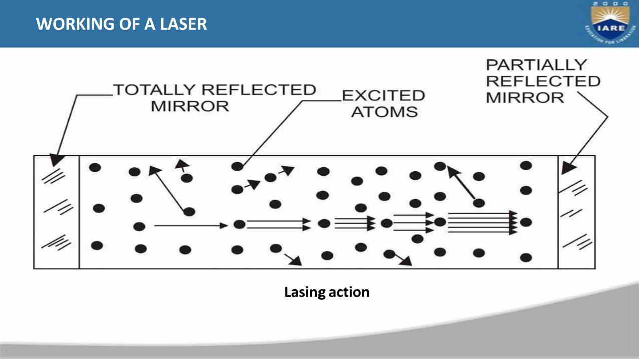
WORKING OF A LASER
Lasing action

LASING MEDIUM
• Many materials can be used as the heart of the laser. Depending on the
lasing medium lasers are classified as solid state and gas laser. Solid-state
lasers are commonly of the following type
• Ruby which is a chromium – alumina alloy having a wavelength of 0.7 μm
• Nd-glass lasers having wavelength of 1.64 μm
• Nd-YAG lasers having wavelength of 1.06 μm
• These solid-state lasers are generally used in material processing.
• The generally used gas lasers are
• Helium – Neon
• Argon
• CO2 etc.

• Laser – Material Interactions
• A great advantage of laser machining is capability to machine any kind of
material, not necessarily conductive, depending on laser intensity and
interaction time.
• In contrast to some other processes, laser operates using high energy photons
therefore there is not a typical tool as the laser beam directly targets the work-
piece and machines breaking the work-piece chemical bonds.
• Laser ablation mechanism makes it possible to introduce the desired shape
geometry of the work-piece without any prior preparations.

• The laser machining is driven by pyrolitic and photolitic
• mechanisms.
• In pyrolitic mechanism the laser energy is absorbed by the material surface layer
resulting in temperature rise, melting and evaporation.
• In photolitic mechanism laser light introduces chemical reaction, which may
cause the material to disintegrate.
• For metal, ceramic and plastic materials pyrolitic is the leading material removal
mechanism.
• When the laser beam targets the work-piece several affects arise: reflection,
absorption, conduction, melting and vaporisation.

• The surface reflectivity depends on the surface roughness and laser wave
length.
• Generally, the longer the wave length, the higher the reflectivity becomes,
hence the absorption decreases.
• Therefore the highest rates of absorption excimer lasers can offer, due to the
shortest operational wave length.
• The temperature also influences reflection/absorption.
• The higher the temperature, the higher the absorption occur, however the main
factor influencing absorption is the laser wavelength.

LASER BEAM MACHINING
Laser beam Machining: a) by long pulses (15 ns). B) short pulses ( 150 fs)

PROCESS PARAMETERS
• LBM processes to a great extent depend on the work- piece properties, laser
intensity and interaction time. For every material there is a threshold intensity
that needs to be achieve for evaporation to occur.

• All conventional LBM processes are located slightly above melting line that
enables melting and then evaporation.
• Process employing ultrashort pulsed lasers are situated well above situated well
above melting line, therefore it is more likely to evaporate material minimising
the stage of melting.

• Material Removal Rate
• The basic assumptions to analyze the material removal process are:
• The intensity of LASER beam does not vary with time.
• LASER beam is uniform over the entire area of
• hotspot.
• The material being removed is both melting and evaporating.
• The steady state ablation is characterized by constant rate of material removal
and by the establishment of a steady state distribution.

• According to the above assumptions, the steady temperature
distribution is given by,
• Where,
• T = temperature at distance x below the ablating surface,
• To = initial uniform temperature of the work piece, Tm =
melting point of the work piece
• V = steady ablation velocity,
• a = thermal diffusivity of work piece, i.e., (K/ρ) * Cp
• K, , Cp= thermal conductivity, density, and specific heat,
• respectively, of the work piece.

After steady ablation is realized, the relationship between the intensity, exposure time, thickness of material which has been removed, and thermal
properties of the material is:
Where, t is the exposure time.

LASER CONSTRUCTION
Solid-state laser with itsoptical pumping unit
Working of a solid-state laser
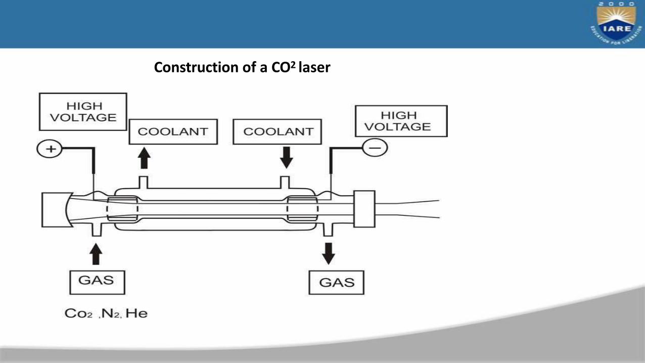
Construction of a CO2 laser

CAPABILITY AND PROCESS CHARACTERISTICS OF DIFFERENT LASERS

LBM – APPLICATIONS
• Laser can be used in wide range of manufacturing applications
• Material removal – drilling, cutting and tre-panning
• Welding
• Cladding
• Alloying
• Drilling micro-sized holes using laser in difficult – to – machine materials is
the most dominant application in industry. In laser drilling the laser beam is
focused over the desired spot size. For thin sheets pulse laser can be used.
For thicker ones continuous laser may be used.


Laser in Micromachining
PVC photolytic ablation
Metal pyrolitic ablation
Multilevel microsystem components
Feature size 20
– 40μm

Diesel Injection Nozzle drilled by CVL

LBM – Advantages
• In laser machining there is no physical tool. Thus no machining
• force or wear of the tool takes place
• Large aspect ratio in laser drilling can be achieved along with acceptable accuracy
or dimension, form or location
• Micro-holes can be drilled in difficult – to – machine materials
• Though laser processing is a thermal processing but heat affected zone specially
in pulse laser processing is not very significant due to shorter pulse duration

LBM – LIMITATIONS
• High initial capital cost
• High maintenance cost
• Not very efficient process
• Presence of Heat Affected Zone – specially in gas assist CO2
• laser cutting
• Thermal process – not suitable for heat sensitive materials like aluminium glass
fibre laminate as shown in Fig.
• Aluminium Glass Fibre Laminate – heat sensitive glass fibre layer due to presence
of resin as binder

MODULE–V
PLASMA MACHINING
Application of plasma for machining, metal removal mechanism, process parameters, accuracy and surface finish
and other applications of plasma in manufacturing industries; Chemical machining principle, maskants, etchants,
applications.
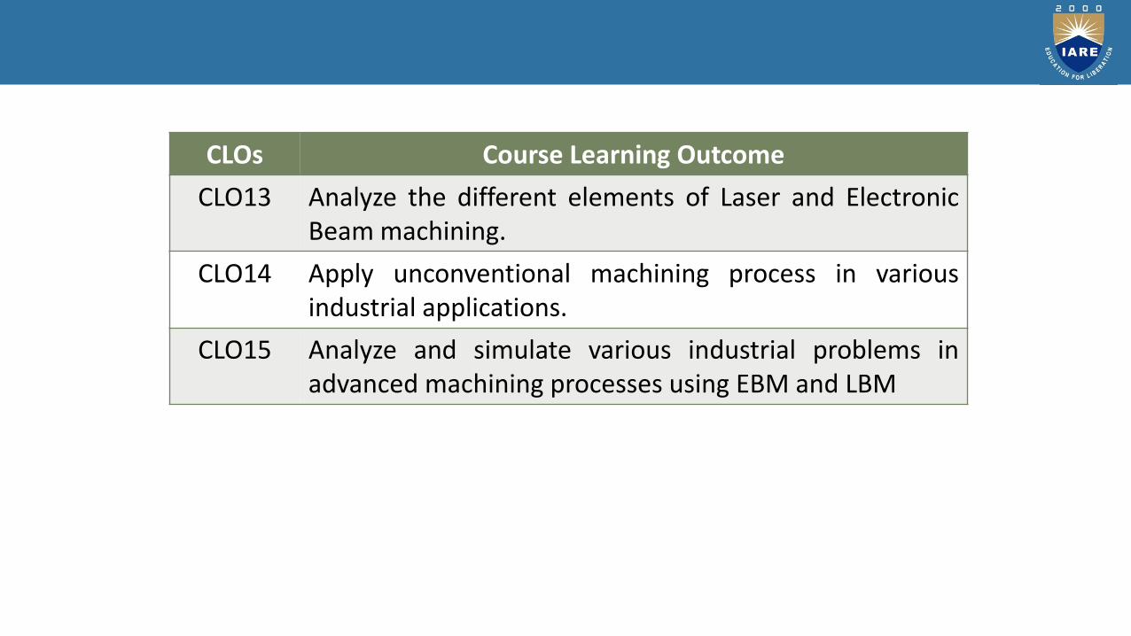
CLOs Course Learning Outcome
CLO13 Analyze the different elements of Laser and ElectronicBeam machining.
CLO14 Apply unconventional machining process in variousindustrial applications.
CLO15 Analyze and simulate various industrial problems inadvanced machining processes using EBM and LBM

CONTENTS
2
• Introduction• Working Principle of PAM• Process Details of PAM• Applications of PAM• Advantages of PAM Process• Disadvantages of PAM Process• Various types of PAM processes• Conclusion• References

INTRODUCTION
• The plasma arc machining process was introduced to the industries in 1964 as a
method of bringing better control to the arc welding process in lower current ranges.
• Plasma-arc machining (PAM) employs a high-velocity jet of high- temperature gas to
melt and displace material in its path.
• Today, plasma retains the original advantages it brought to industry
• by providing an advanced level of control and accuracy.

• Gases are heated and charged to plasma state.
• Plasma state is the superheated and electrically
ionized gases at approximately 5000⁰C.
• These gases are directed on the workpiece in the
form of high velocity stream.
WORKING PRINCIPLE OF PAM
Plasma Arc machinining

PROCESS DETAILS OF PAM
• Plasma gun
• Power supply
• Cooling mechanism
• Work piece

PLASMA GUN
• The plasmagun consists of a tungsten electrode fitted in the chamber.
• The electrode is given negative polarity and nozzle of the gun is given positive polarity.
• A strong arc is established between the two terminals anode and cathode.
• There is a collision between molecules of gas and electrons of the established arc.
• Gas molecules get ionized and plasma state is formed.
• Plasma is directed to the workpiece with high velocity.

POWER SUPPLY AND TERMINALS
• Power supply (DC) is used to develop two terminals in the plasma gun.
• A tungsten electrode is inserted to the gun and made cathode and nozzle of the
gun is made anode.
• Heavy potential difference is applied across the electrodes to develop plasma state
of gases.

• Hot gases continuously comes out of nozzle so there are chances of its over
heating.
• A water jacket is used to surround the nozzle to avoid its overheating Work piece
• Work piece of different materials can be processed by PAM process.
• Ex: aluminium, magnesium, stainless steels and carbon and alloy steels.

APPLICATIONS OF PAM
• In tube mill application.
• Welding of cryogenic, aerospace and high temperature corrosion resistant alloys.
• Nuclear submarine pipe system.
• Welding steel Rocket motor case.
• Welding of stainless steel tubes.
• Welding titanium plates up to 8mm thickness.

ADVANTAGES OF PAM PROCESS
• It gives faster production rate.
• Very hard and brittle metals can be machined.
• Small cavities can be machined with good dimensional accuracy.
• Disadvantages of PAM Process
• Its initial cost is very high.
• It is uneconomical for bigger cavities to be machined.
• Inert gas consumption is high.

VARIOUS TYPE OF PLASMA ARC CUTTING
• Conventional Plasma Arc Cutting
• Arc is constricted by a nozzle only; no shielding gas is added.
• Cutting gas is tangentially injected to the electrode.
• The swirling action of the gas causes the cooler portions of the gas to move radially
outward forming a protective boundary layer on the inside of the nozzle bore.
• This helps prevent damage to the nozzle and extends its life.

CONVENTIONAL PLASMA ARC CUTTING
Typical PAM setup

VARIOUS TYPE OF PLASMA ARC CUTTING
• Air Plasma Arc Cutting
• Air plasma arc cutting was introduced in early 1960s for cutting mild steel.
• Oxygen in the air provides additional energy from the exothermic reaction with
molten steel, boosting cutting speeds about 25 percent.
• Process can also be used to cut stainless steel and aluminum, the cut surface will
be heavily oxidized and thus can be unacceptable for some applications.

AIR PLASMA ARC CUTTING SETUP
AIR PLASMA ARC CUTTING SETUP

• Dual-flow PAC is a slight modification of conventional PAC.
• Secondary shielding gas is shielding gas around the nozzle.
• The cutting gas is usually nitrogen.
• The shielding gas is selected according to the metal to be cut.
• Cutting speeds are slightly better than those of conventional PAC on mild steel, but the
cut quality is not acceptable for some applications.
• Cutting speed and quality on stainless steel and aluminum are essentially the same as
with conventional PAC.
VARIOUS TYPE OF PLASMA ARC CUTTING
Dual-flow Plasma Arc Cutting

DUAL-FLOW PLASMA ARC CUTTING

VARIOUS TYPE OF PLASMA ARC CUTTING
• Underwater Plasma Arc Cutting
• Underwater PAC is suited to numerically(NC) shape cutting and produces a noise level
of 85dB or less under normal operating conditions.
• In comparison,conventional PAC typically produces noise levels in the range of 105 to
115 dB.
• Underwater cutting also nearly eliminates ultraviolet radiation and fumes.
• Steel plate being cut is supported on a cutting table with the top surface of the plate 2
to 3 inches underwater.

VARIOUS TYPE OF PLASMA ARC CUTTING
• Underwater Plasma Arc Cutting
• Underwater PAC is suited to numerically(NC) shape cutting and produces a noise level of
85dB or less under normal operating conditions.
• In comparison,conventional PAC typically produces noise levels in the range of 105 to 115
dB.
• Underwater cutting also nearly eliminates ultraviolet radiation and fumes.
• Steel plate being cut is supported on a cutting table with the top surface of the plate 2 to
3 inches underwater.

VARIOUS TYPE OF PLASMA ARC CUTTING
• Underwater Plasma Arc Cutting
• Underwater PAC is suited to numerically(NC) shape cutting and produces a noise level
of 85dB or less under normal operating conditions.
• In comparison,conventional PAC typically produces noise levels in the range of 105 to
115 dB.
• Underwater cutting also nearly eliminates ultraviolet radiation and fumes.
• Steel plate being cut is supported on a cutting table with the top surface of the plate 2
to 3 inches underwater.

CHEMICAL MACHINING
Chemical machining (ChM) Was developed based on the observation that chemicalsattack metals and etch them by using chemical dissolutions.
ChM is the removalof material bychemical attack by a corrosive liquid.
The areas of the work piece which are not to be machined are masked.
• The work piece is either immersed in or exposed to a spray of chemical reagent.
• ChM was basically developed for aerospace industry to maintain strength of part
at reduced weight.

• An etchant resistant mask, made typically of rubber or plastic is used toprotect those parts of the component from which no material is to beremoved.
• Part to be machined is defined by any one of the procedures: scribing &removing the coating, exposing to light & dissolving unexposed regionStrong acid or alkaline solution is used to dissolve materials selectively.
• Chemically resistant coating is applied to protect surfaces not to be machined.


Etch factor after CHM

MASKANTS
Maskants are generally used to protect parts of the workpiece where Chemical Dissolutionaction is not needed. Synthetic or rubber base materials are frequently used.
Maskants should possess the following properties:
1. Be tough enough to withstand handling
2. Adhere well to the workpiece surface
3. Scribe easily
4. Be inert to the chemical reagent used
5. Be able to withstand the heat generated by etching
6. Be removed easily and inexpensively after etching
ETCHANTS
Etchants are acid or alkaline solutions maintained within a controlled range of chemicalcomposition and temperature. Their main technical goals are to achieve the following:
1. Good surface finish
2. Uniformity of metal removal
3. Control of selective and intergranular attack
4. Maintenance of personal safety
5. Best price and reliability for the materials to be used in the construction of the process
tank
1. Maintenance of air quality and avoidance of possible environmental problems
2. Low cost per unit weight dissolved
3. Ability to regenerate the etchant solution and/or readily neutralize and dispose of its
waste products

Surinarayana
STEPS IN CHEMICAL MACHINING
The 4 steps in chemical machining are as follows:
•Part preparation: cleaning.
•Masking: application of chemically resistant material
•Etching: dip or spray exposure to etchants
•Mask removal and finishing: stripping the maskant and cleaning the part & inspection and other processing

Surinarayana
TYPES OF MASKING METHODS USED IN CHM
Cut and peel method Screen resist method Photo resist method
Cut and peel maskants
• Film of chemically resistant material is applied to the work piece by dipping, spraying or flow coating.
• Vinyl and styrene are used.
• Rubbery film is then cut & peeled away selectively.
• Manual scribing of mask material usually achieves an accuracy of ±0.13 mm to ±0.75 mm.

Mask material is applied to the work piece surface by printing, using stencils and a fine polyester or stainless steel mesh screen.Relatively thi coatings with tolerances held to ±0.05 to ±0.18 mm are obtained by screen printing.Etching depths are restricted to about 1.5 mm because of thinness of the coating.
Photo resist maskantsPhoto resist mask is quite widely used & is often referred to as photochemical machining.Produces intricate & finely detailed shapes using a light activated resist materials.Work Piece coated with photo resist material & a master transparency is held against the Work Piece, while exposure to UV rays takes place.
Light activates the photo resist material in those areas corresponding to opaque parts
Tolerances of ±0.025 to 0.005 mm can be produced.
SCREEN RESIST MASKANTS
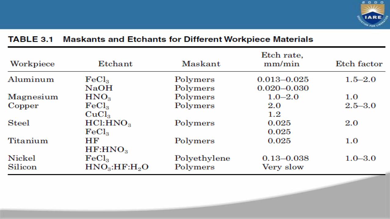

CHEMICAL MACHINING PROCESSES
• Chemical milling
• Chemical blanking
• Chemical engraving
• Photochemical machining

CHEMICAL MILLING
1. In chemical milling, shallow cavities are produced on plates, sheets, forgings and extrusions.
2. The two key materials used in chemical milling process are etchant and maskant.
3. Etchants are acid or alkaline solutions maintained within controlled ranges of chemical composition and temperature.
1. Maskants and resists are workpiece coatings used to protect areas of the workpiece, which are not to be exposed to the etchant and to define exposed areas for etchant attack.
2. Chemical milling is used in the aerospace industry to remove shallow layers of material from large aircraft components, missile skin panels, extruded parts for airframes.

CHEMICAL MILLING
Typical ChM surface

CHEMICAL BLANKING
• Chemical blanking is used to etch entirely through a metal part.
• In chemical blanking, holes and slots that penetrate entirely through the material are produced, usually in thin sheet materials.
• Used to produce fine screens, flat springs, etc…
• Very cheap but efficient.

Fig : parts profiled by chemical blanking process
CHEMICAL ENGRAVING
Chemical Engraving is the practice of incising a design on to a hard, usually flat surface, by cutting grooves into it. The result may be a decorated object in itself, as when silver, gold, steel, or glass are engraved, or may provide an printing plate, of copper or another metal, for printing images on paper as prints or illustrations.copper
Types of engraving
•Wood Engraving Copper and Steel Engravings
• Laser engraving

PHOTO CHEMICAL MACHINING (PCM)
• Photochemical machining (PCM) is a variation of chemical machining (ChM) where the chemically resistant mask is applied to the workpiece by photographic techniques.
• The two processes are quite similar because they both use chemicals to remove metal by the Chemical Dissolution action and some of the steps required in both cases are similar.
• ChM is usually used on three dimensional parts originally formed by another manufacturing process, such as forging and casting of irregular shapes.
• As with photochemical machining, areas not to be machined are masked from the Chemical Dissolution action of the chemical solution.
• Photochemical machining creates new parts from thin materials.

PROCESS
• The first step includes the production of the required shape on a photographic film or glass plate, termed the photo-tool.
• Computer-aided design (CAD) artwork creates the required part shape, which is used as the primary image for the photo-tool.
• The sheet metal is chemically cleaned, and coated with a light-sensitive photoresist film.
• The photoresist will adhere to the part surface and act as a stencil resist protecting the surface during etching.
• In some cases, the photoresist is a liquid and the part has to be dip coated and dried.

PROCESS
• The resist laminated, or coated, metal is then placed under the photo-tool and exposed, in a vacuum, to an ultraviolet light source. This transfers the image precisely onto the resist and, after developing, becomes a replica of the desirable geometry.
• The exposed image is then developed by immersion or spraying. Each photoresist has its own developing solution, such as water, alkaline solution, hydrocarbons, or solvents.
• The exposed material is then washed to remove the unexposed photoresist on the areas
to be chemically etched

• Photochemical machining (PCM), also known as photochemical milling or photoetching, is the process of fabricating sheet metal components using a photo resistand etchants to corrosively machine away selected areas.
• PCM can be used on virtually any commercially available metal or alloy, of anyhardness. It is limited materials 0.0005 to 0.080 in (0.013 to 2.0 mm) thick. Metalsinclude aluminium, brass, copper, inconel, manganese, nickel, silver, steel,stainless steel, zinc and titanium
Surinarayana
PHOTO CHEMICAL MACHINING (PCM)

Process steps for photochemical machining
Photo Chemical Machining (PCM)
PHOTO CHEMICAL MACHINING (PCM)

ADVANTAGES OF CHEMICAL MACHINING
1. Easy weight reduction2.No effect of work piece materials properties such as hardness3.Simultaneous material removal operation4.No burr formation5.No stress introduction to the work piece6.Low capital cost of equipment7.Easy and quick design changes8.Requirement of less skilled worker9.Low tooling costs10.The good surface quality11.Using decorative part production12.Low scrap rates (3%)

DISADVANTAGES
• Difficult to get sharp corner
• Difficult to chemically machine thick material (limit is depended onwork piece material, but the thickness should be around maximum 10 mm)
• Scribing accuracy is very limited, causes less dimensional accuracy.
• Etchants are very dangerous for workers.
• Etchant disposals are very expensive

Applications
High Precision Parts and Decorative Items
• Gaskets
• Washers
• Sensors
• Nameplates
• Jewelry
• Microprocessor Chips

REFERENCES
• Modern machining process by P C Pandey.
• www.ieee.org
• www.chemicalmachining.org
• www.photochemicalmachining.com
• Mechanicalr13.blogspot.in