under floor air distribution (ufad) solutions · the aet-c zonal mixing system under floor supply...
TRANSCRIPT

OVERHEAD SYSTEM UFAD SYSTEM
UNDER FLOOR AIR DISTRIBUTION (UFAD) SOLUTIONS
Indian Green Building Council

think cool...
02
think clean...

03
UFAD System DescriptionAn Underfloor air distribution (UFAD) system uses the open space (underfloor plenum) between a structural slab and the under side of a raised access floor system to deliver conditioned air to supply outlets located at or near floor level within the breathing zone ( upto 1.8 to 2 mtrs height) of the space.
By combining a building's HVAC system with all major power, voice, and data cabling into one easily accessible service plenum under the raised floor, significant improvements can be realized in terms of increased flexibility and reduced costs associated with reconfiguring building services. These raised floor systems are particularly appropriate for office buildings housing today's businesses with their typically extensive use of information technologies and high churn rates complying with global norms of �Green Building� concepts.
Benefits of UFAD System1.Improved thermal comfort : By allowing individual occupants to control their local thermal environment, their individual comfort preferences can be
accommodated.
2.Improved ventilation efficiency and indoor air quality : Improvement in ventilation and indoor air quality at breathing level can be expected by delivering the fresh supply air at floor level near the occupants and returning at ceiling level.
3.Reduced energy use : Energy saving for UFAD system over conventional overhead system can be associated with cooling and fan energy saving.
4.Reduced life-cycle building costs : By integrating a building HVAC and cable management systems into easily accessible under floor plenum, in house maintenance personnel can carry out reconfigurations at significantly reduced cost using simple tools and hardware .
5.Reduced floor-to-floor height in new construction : Buildings using UFAD system have potential to reduce floor-to-floor heights comparedto projects with conventionally designed ceiling based system.
6.Improved productivity and health : Research evidence suggests that occupants satisfaction and productivity can be increased by givingindividuals greater control over their local environment and by improving the quality of indoor environment.

B R E A T H I N G Z O N EW E L L M I X E D
I DON’T CARE ZONE
023C
025C
027C
022C
1.8m
016C0-18
022C
2.4m
04
AET brings PleinAir to India & S. E. Asia- A product of AirFixture USAÒ
AET�s new PleinAir system can overcome the problem of discomfort traditionally associated with VAV solutions by introducing its key element, the AirFixture damper using time modulation control - the new control technique for managing the way conditioned air is introduced into a space. This new device eliminates instances of poor air distribution at part load conditions in fixed slot VAV terminals and improvement in air distribution is immediately noticeable.
The PleinAir system only needs between 7 and 12 Pascals pressure for the Passive Tile Units (PTU) to distribute the air effectively into the room space above the floor. However in part load conditions as the central plant varies its volume, the Air Fixture specially designed damper fitted to the PTUs will start to sequence on/off according to room load demand. These dampers close for brief moments and thus the correct volume of air is introduced in sequence through open grilles in this �Time Modulated� way. The reduced numbers of PTUs operate with full flow thus maintaining the originally designed air throw. The alternating performance of the PTUs is based around a 6 second timing sequence hence ensuring good air distribution in the occupied space at all times. Extensive testing supports this new concept of Variable Air Volume control.
Range of high induction diffusers
CONSTANT VOLUME DIFFUSERWITH PERSONAL CONTROL
VAV TIME MODULATED DIFFUSERWITH SQUARE GRILL
4 WAY DEFLECTIONCONSTANT VOLUME DIFFUSER
VAV TIME MODULATED DIFFUSERWITH ROUND GRILL

25% SMART FIG 7
25% SMART FIG 1125% SMART FIG 1025% SMART FIG 9
25% SMART FIG 8
FIG 650% Flow really means100% flow to 50% of the area
50% SMART FIG 550% Flow with Time Modulation =50% flow to 100% of the area
FIG 4
100% FLOW FIG 20% FLOW FIG 1
Process of Time Modulation
FIG 350% Flow really means 100%flow to 50% of the area
05
Time Modulation by PleinAirThe method of terminal air control has been used successfully in America and the Middle East for more than five years and the system concept has been in use for over eleven years with over 3 million sq m of office buildings successfully air conditioned.
0 0It is often working in ambient conditions up to 60C in the summer and down to minus 28C in the winter
Effective Air Distribution by PleinAir
The first thing to remind ourselves is we are using proven variable volume high induction ratio grilles. PleinAir passive terminals create a cool, forced flow, well mixed breathing zone which should not be confused with the displacement system concept which supplies warmer air at much higher volumes and cannot achieve the cooling loads that the PleinAir system can.
The best way to describe how the terminals work in the space is to use the analogy of a water sprinkler system.
If we take a typical perimeter zone of 6m wide by 4.5m deep we will need 4 cooling terminals. In Fig. 1 we have a No Flow condition and in Fig. 2 we have 100% Flow condition with good air distribution. With traditional damper control at part load condition we have an air throw pattern characteristic with Fig.3 and the typical problem of reduced air throw and the beginning of stagnant areas if part load conditions continue. This situation will only continue to deteriorate as the system throttles back further.
If we now look at Fig. 4 you will see the air distribution pattern when using Time Modulation. Two of the 4 terminals are supplying 100% air flow and after 6 seconds these close and the alternate terminals supply 100% supply air as seen in Figs. 4, 5 and 6.
If the system continues to throttle back to 25% only one terminal supplies air at 100% as in Figs. 7-11 and the terminals open and close in rotation as shown.
06
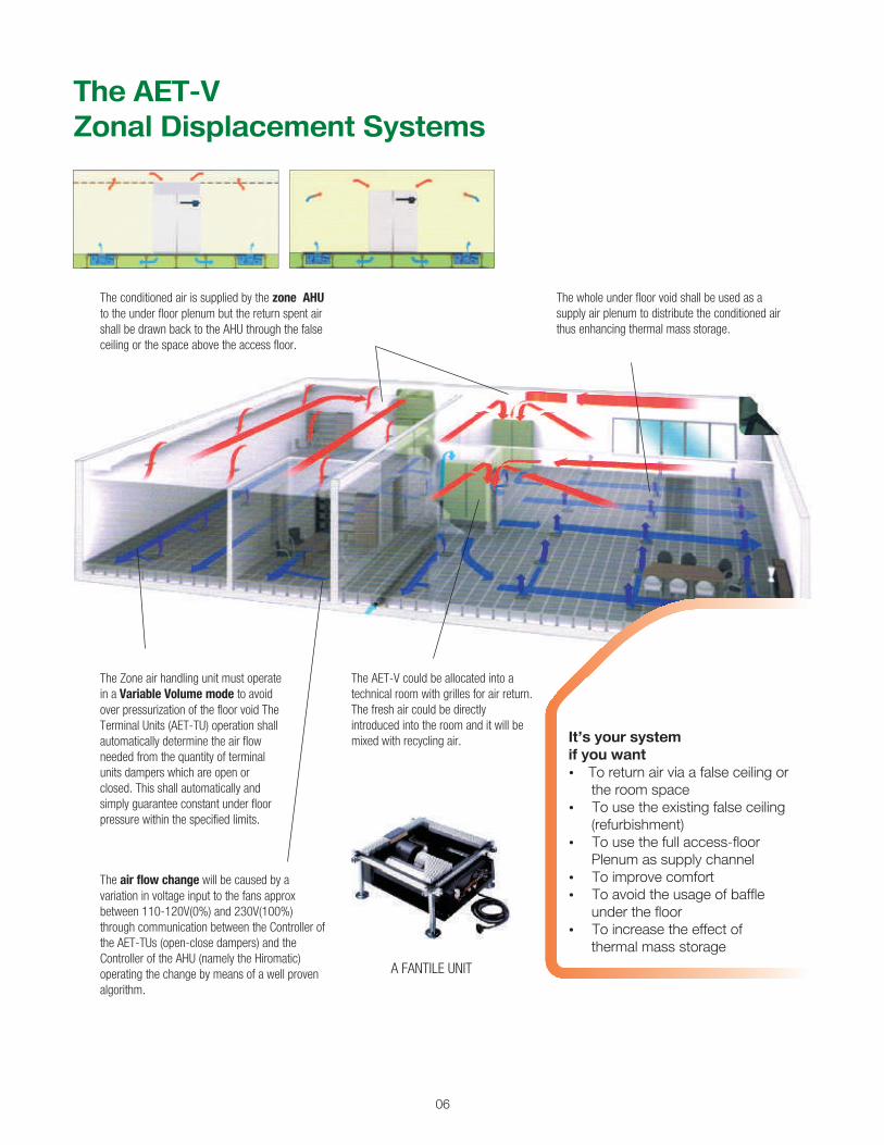
The AET-VZonal Displacement Systems
It�s your systemif you want?To return air via a false ceiling or
the room space?To use the existing false ceiling
(refurbishment)?To use the full access-floor
Plenum as supply channel?To improve comfort?To avoid the usage of baffle
under the floor?To increase the effect of
thermal mass storage
The Zone air handling unit must operate in a Variable Volume mode to avoid over pressurization of the floor void The Terminal Units (AET-TU) operation shall automatically determine the air flow needed from the quantity of terminal units dampers which are open or closed. This shall automatically and simply guarantee constant under floor pressure within the specified limits.
The air flow change will be caused by a variation in voltage input to the fans approx between 110-120V(0%) and 230V(100%) through communication between the Controller of the AET-TUs (open-close dampers) and the Controller of the AHU (namely the Hiromatic) operating the change by means of a well proven algorithm.
The AET-V could be allocated into a technical room with grilles for air return.The fresh air could be directly introduced into the room and it will be mixed with recycling air.
The conditioned air is supplied by the zone AHU to the under floor plenum but the return spent air shall be drawn back to the AHU through the false ceiling or the space above the access floor.
The whole under floor void shall be used as a supply air plenum to distribute the conditioned air thus enhancing thermal mass storage.
A FANTILE UNIT

The AET-CZonal Mixing System
Under floor supply and return channels are created by means of baffles (underfloor air partitioning) placed in the access floor void.
Return air grilles are positioned in the floor over return Plenum to permit the return of spent air to the AHU unit for re-conditioning.
Set into the floor over supply Plenum are individually controlled Fan terminals of either recessed or floor standing configuration. These terminals, AET-TUs., introduce air into the space above in accordance with the dictates of their own on board control system.
AET-C Conditioned Air Modules are suitably located throughout the office space to suit thermal demand and supply conditioned air locally to serve the needs of the space.
The low underfloor pressure in the two sections, supply and return, is kept at the desired level by means of a suitably sized under floor by pass in the underfloor air partitioning, this can be easily changed and baffle can also be repositioned or modified, if necessary as space reconfiguration demands.
It�s your systemif you want to designwithout false ceiling?To reduce overall construction cost?To reduce overall construction time?To design with a false ceiling?To minimise cross contamination risk?To treat air only in the occupied
breathing zone?To improve comfort?To increase the effect of
thermal mass storage?To find a solution in height
limited refurbishmentsA FANTILE UNIT
07

08
Height Saving Benefit
FLOOR-TO-FLOORHEIGHT3400MM
HEADROOM2700MM
UNDERFLOOR VOID 300MM
SLAB 300MM
HEIGHT SAVINGS INEXCESS OF 10%
SLAB 300MM
LIGHTING ZONE 100MM
Floor Designed with UnderfloorAir Distribution System
FLOOR-TO-FLOORHEIGHT3850MM
VENTILATION ZONE600MM
LIGHTING ZONE 100MM
HEADROOM2700MM
CABLING VOID 150MM
SLAB 300MM
SLAB 300MM
Floor Designed with Conventional Overhead System
The Center HongKongHeight saving of
35m ~ 10 storey building
Telecom TowerMalaysia
Height saving of 30 meters
First Point, BAA Gatwick Managed to Construct 1 extra floor
2 2(6,000 m area became 7,500 m area)

UFAD LEED™ CREDIT Points
Optimize Energy Performance 3 to 4 pts
Measurement & Verification 1 pt
Increased Ventilation Effectiveness 1 pt
Construction IAQ Management plan 1 pt
Controllability of Systems 1 pt
Thermal Comfort 1 pt
Total Point Opportunity » 8 to 9 Points
LEED™ CREDIT
UNITILE RAISED ACCESS FLOOR
Recycled Content 1 to 2 pts
Local/Regional Materials 1 to 2 pts
Low-Emitting Materials 1 to 3 pts
Total Additional Points 3 to 7 Points
Points
»
09
Why Flexiblespace from AET ???Flexibility
Ease of Installation
Avoidance of Co-ordination problems
Operation Costs
Maintenance Aspects
Safety
Fit Out Contractor Work
Potential LEED Points with Flexible Space Concept
Because the rate of business growth and the rate of change in office equipment technology places “flexibility” of systems much higher on the list of priorities.
In speculative developments the need to meet unknown requirements of unknown user’s effectively must be the aim.
The Flexiblespace system permits major swings in usage in the space and the incorporation of such a system virtually future-proofs the building’s ability to service change for the expected life of the building.
Conventionally, designs are carried out against a set of assumed design criteria and systems are installed to meet them. In some cases the incoming user’s requirements are for less than the initial design provided and this is wasteful. In other cases the system provided falls seriously short of the user’s requirements and the whole system requires changing. This too is wasteful.
With the Flexiblespace systems approach the demands of each incoming user can be met quickly and effectively and during the occupancy can be easily adapted and upgraded to meet the increasing or decreasing needs in each area of the space occupied. With simple facility management, redundant equipment from one area can be re-utilized elsewhere.
Partitioning changes to meet new working arrangements are easily catered for and simple relocation or provision of additional diffuser and / or fan air terminal in the floor quickly adapts the air conditioning.
This flexibility permits a higher efficiency of space usage and maximizes business activity to the advantage of the owner and user. Longer occupancies can be achieved because the building can continue to meet the user’s needs.
Because with the Flexiblespace systems heat loads in area’s can change without the need to re-design ductwork and pipework thus reducing engineering and drafting inputs.
For example, to double the cooling demand in a cellular office, an additional diffuser and / or fan air terminal would be brought to the room, a floor tile lifted and the diffuser and / or fan terminal inserted inits place and plugged into the below-floor power supply. This operation takes minutes rather than days as with conventional systems.
Because with conventional systems the major co-ordination problems occur attempting to route ductwork, pipework and other services in false ceiling areas along with lighting, power and the false ceiling support structure itself. Pressure-testing of pipework and ductwork and final fixing of grilles and diffuser’s into the finished false ceiling cause major problems and damage.
The Flexiblespace system does away almost entirely with the need for horizontal air conditioning ductwork and pipework and thus reduces co-ordination problems dramatically.
With correct programming it is possible to eliminate the need for multiple trade activity in areas, resulting in reduced damage to finished work and a faster overall installation programme.
Because the Flexiblespace space system operates with very low air pressure within the floor void ( in the order of 20 pascals ).As a result, installed fan power is approximately 50 % of that required fora conventional system.
The central plant operation costs are similar to those of a fan coil system with the advantage of reduced fan power on the ventilation system as a result of the reduction of horizontal ductwork and the associated resistance
Because the floor void being easily accessible and highly reduced or no duct work, the system can be far more easily cleaned. Trained maintenance staff can simply lift the floor tiles and vacuum if the need arises, but in tests the system has been shown to be generally far cleaner in operation than conventional systems.
Because the provision of all essential services below an easily accessible raised floor does away with the need for erection towers and high level working.
Accuracy of electrical work can be much improved and many of techniques employed in the Flexible Space approach permit factory assembly of modular units further improving quality control and accuracy of installation.
The removal of high level piping and the effects of flooding during commissioning are avoided not only improving safety, but also reducing possible damage to second fix trades, carpets and other finishes.
Re-configurations of office spaces later in the life of the building are much more easily and safely carried out.
Because the Flexible Space system incorporates a raised access floor, the need for leveling screeds is totally eliminated with the tolerances being taken up by the adjustable pedestals of the raised floor.
It avoids entirely the early jumble of trades fighting for space during the first fix crevassing exercise, permitting a more easily managed, faster constructed, and much tidier and safer site generally.
It is an ideal system for the shell and core approach to building as no decisions on heating and cooling loads, duct layouts or power data and telecom provisions have to be made until the user requirements are defined.
™
™
Energy & Atmosphere
Optimized energy performance – reduce building energy use below levels specified in ASHRAE Standard 90.1 (1-10 pts)
Indoor Environmental Quality
Improved ventilation effectiveness – performance of UFAD system results in ventilation effectiveness greater than 0.9 (average for overhead mixing systems), as measured according to ASHRAE Standard 129-1997 (1 pt)
Controllability of systems – provide individual control of thermal, ventilation, and lighting systems to support improved occupant comfort, health, and productivity (1-2 pts)
EVENTUALLY UTILIZING UFAD SYSTEM LEADS TOWARDS GAINING LEED POINTS MEETING OBJECTIVES OF GREEN BUILDING COUNCIL.

General Office Areas
Public Libraries
Call Centers
Emergency Ops / 911 Centers
Training Rooms
Video Conferencing Centers
TV / Radio Stations
Trading Floors
Executive Offices
Museums
Casino Gaming Floors
Computer Rooms
10
ApplicationsUFAD systems are well suited for buildings with open plans in which adjustable diffusers can allow occupants to individually control their local workstation environment like.

11
Existing buildings with
UFAD systems
Multi-Tenant Buildings
American Waterworks Bldg.St. Louis, MO
One Century PlaceNashville, TN
Foundry SquareSan Francisco, CA
160 King StreetSan Francisco, CA
Mission Bay CatellusSan Francisco, CA
The Soffer Tech Office Bldg.Pittsburgh, PA
Data Center / Telecom Buildings
AT&T
GTE
Global Crossing
INFLOW Data Centers
Level 3 CoLo Centers
MCI Worldcom
NYNEX
Sprint PCS
Call Center Buildings
American Express
Blue Cross Blue Shield
British AirwaysNew York, NY
Dell Computers
Hewlett Packard
IBM
Motorola
United Parcel ServiceOakland, CA
Financial Buildings
Jack Henry & Associates
Capital OneTampa, FL
Chase Financial Services
Citibank
Lloyd’s of LondonLondon, England
Morgan Stanley Dean Witter
Shearson Lehman
American Express
World Bank HeadquartersWashington, DC
www.flexiblespace.com I www.unitedinsulation.com I www.hitechofficesystems.com
Principals :
Advanced Ergonomic Technologies Ltd. UK
The Center 201-203, London Road,East Grinstead, West Sussex UK, Rh19 1HATel : +44(0)1342 310400Fax : +44(0)1342 310401
Mumbai
M. T. Rasiwala - DirectorEmail:[email protected]
Jayant Patekar I Cell : +91-9004050768Email:[email protected]
Unit No 2-G, Laxmi Industrial Estate,New Link Road, Andheri (West),Mumbai 400053.Tel : +91-22-2630 5270/72Fax : +91-22-2630 5273
Bengaluru
Prabhu S. A. I Cell : +91-9845212183Email:[email protected]
Gala No 58, SL No 35/2,Singasandra Gramathana,Begur Hobli, Hosur Road,Bengaluru 560068.Tel: +91-80-3295 6871Telfax : +91-80-4110 0518
Authorized accredited installer ofAET in India & S. E. Asia
A product ofHi-Tech Office Systems
Manufacturer ofRaised Access Floor Systems