underground coal gasification - department of energy
TRANSCRIPT
.
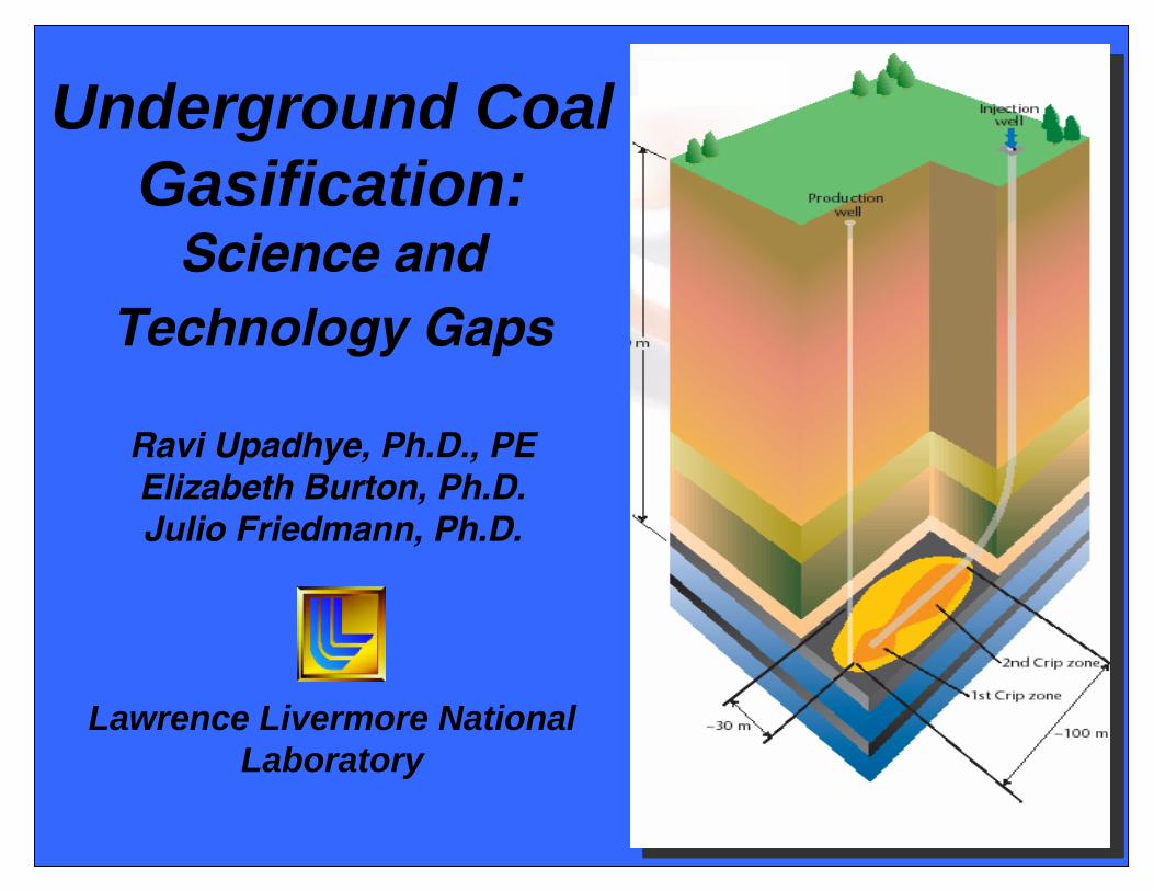
Underground Coal Gasification:
Science and Technology Gaps
Ravi Upadhye, Ph.D., PEElizabeth Burton, Ph.D. Julio Friedmann, Ph.D.
Lawrence Livermore National Laboratory
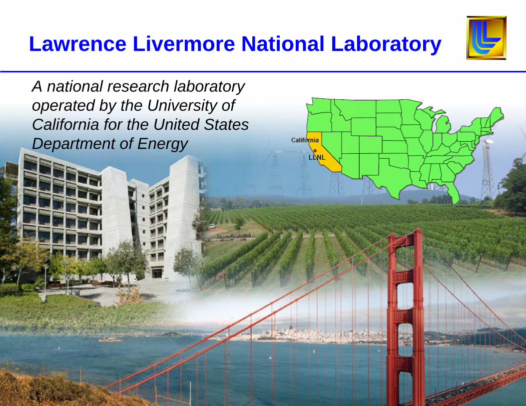
Lawrence Livermore National Laboratory
A national research laboratory operated by the University of California for the United States Department of Energy
DOE/LLNL Activity in UCG
• Invented CRIP (controlled retractable injection point) process (1974-1985)
• Conducted numerous field tests (Hoe Creek, Hanna, Centralia)
• Developed and validated cavity growth models • Developed methodologies for process control monitoring• Developed a CFD-based gasification model of the UCG
process and integrated it with Aspen Plus • Developing tools for site assessment• Developing models for environmental risk assessment• Applying carbon management and CO2 sequestration
expertise to evaluate UCG-CCS• Completed draft report on UCG best practices and lessons
learned
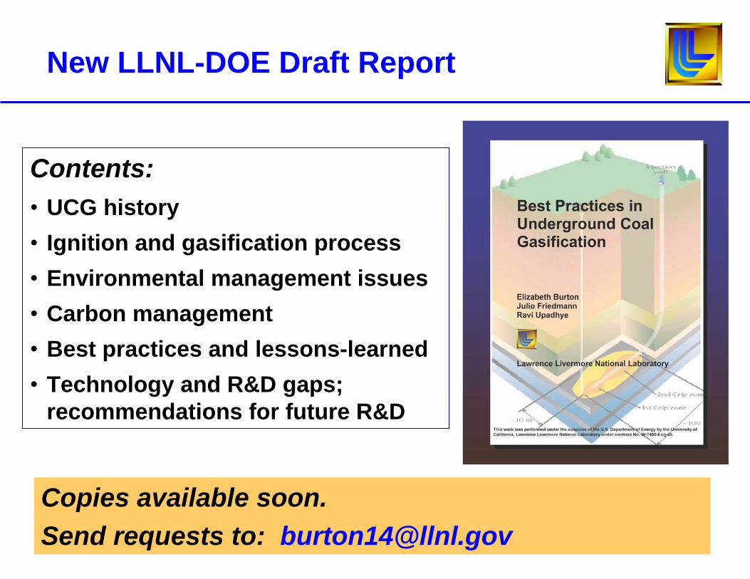
New LLNL-DOE Draft Report
Contents: • UCG history• Ignition and gasification process• Environmental management issues• Carbon management• Best practices and lessons-learned• Technology and R&D gaps;
recommendations for future R&D
Copies available soon.Send requests to: [email protected]
Why Consider Underground Coal Gasification?
• Eliminates conventional coal mining, reducing operating costs, surface damage, eliminating mining safety problems
• Accesses otherwise un-mineable coals (deep or thin seams), increasing exploitable reserves
• Needs no surface gasification facilities, reducing capital costs
• Leaves gasification residuals underground• Eliminates costs, facilities, and environmental issues
associated with transport/storage of mined coal or coal gasification residuals (e.g., ash)
• Reduces overall greenhouse gas emissions and has advantages for geologic carbon storage
Timeliness of Underground Coal Gasification R&D Investment
• Economic pressure to find alternative fuel resources given high cost of oil and natural gas
• Increased security risk with continued dependence on imported fuel supplies
• Access presently un-mineable coal resources– in U.S., UCG increases exploitable coal resources by ≥ 3 times
• Potential to optimize UCG as a cost-effective clean-coal technology:– Reduced greenhouse gas emissions per unit coal gasified– Potential for combined UCG-CCS– Reduced overall environmental impact
Increased recent interest in UCG technology globally creates opportunities to leverage R&D and share lessons-learned and
best practices
Limitations and Concerns for UCG
• UCG has produced significant groundwater contamination and ground subsidence in some previous operations
• The increase in exploitable coal possible with UCG may be less when site selection is constrained by geologic and hydrologic criteria to protect the environment
• UCG is a non-steady state process-- operations cannot be controlled to the same extent as surface gasification– Process variables vary as burn progresses and can only be
estimated– Flow rate and composition (heating value) of product gas will vary
over time
• Business case for UCG will remain difficult until there are enough UCG facilities (power, syngas, chemical feedstocks) to provide economic data
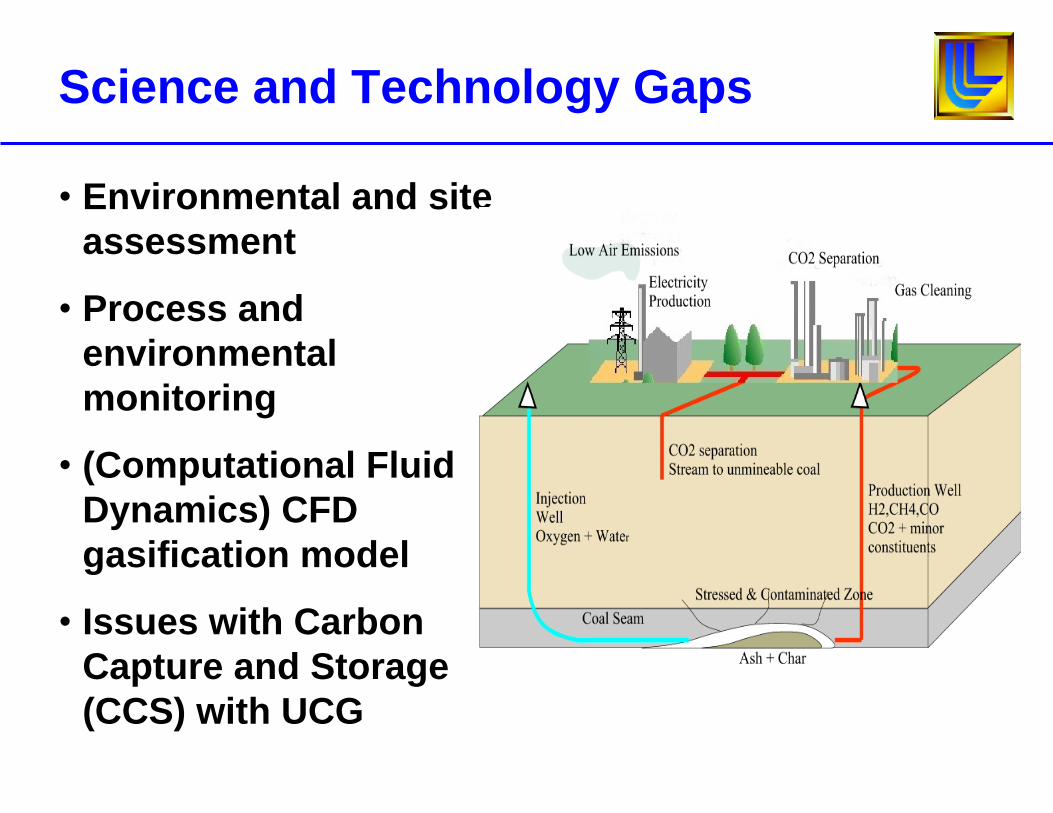
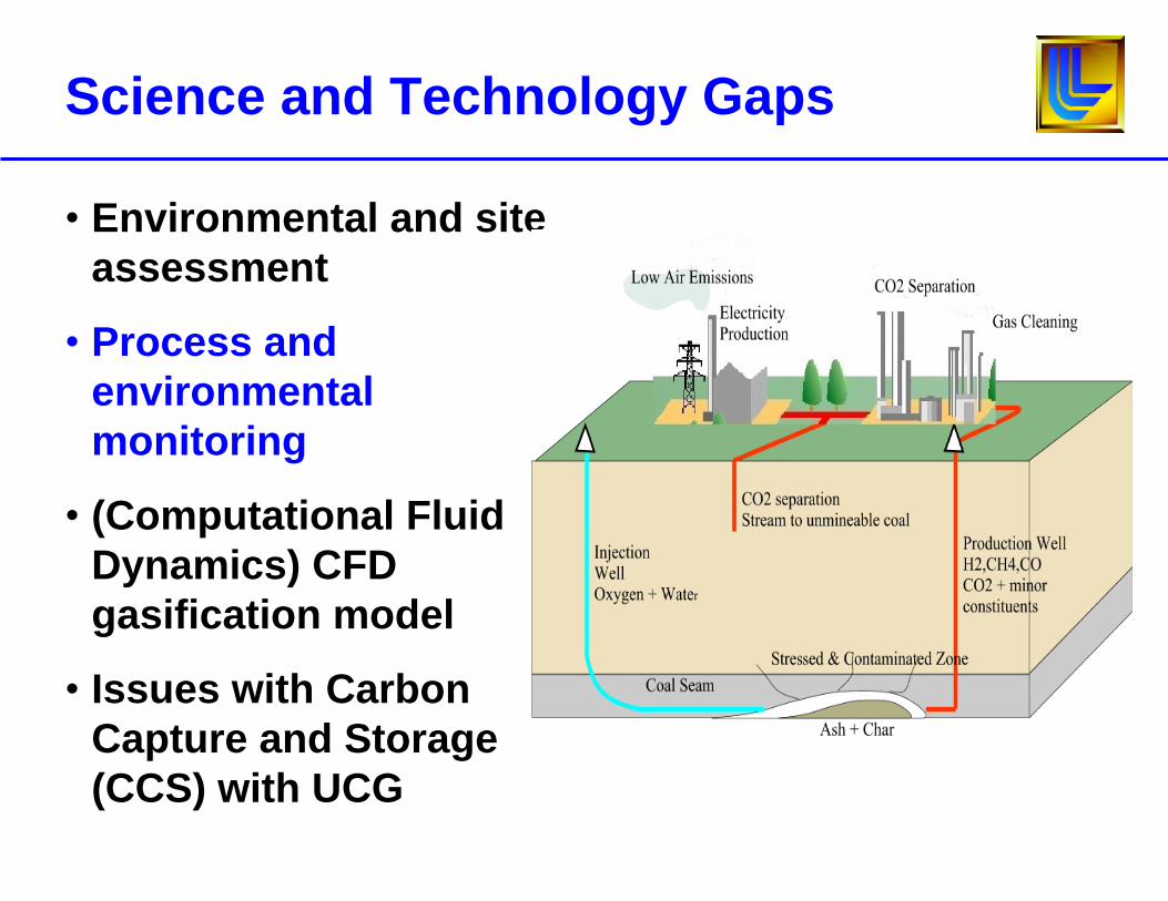
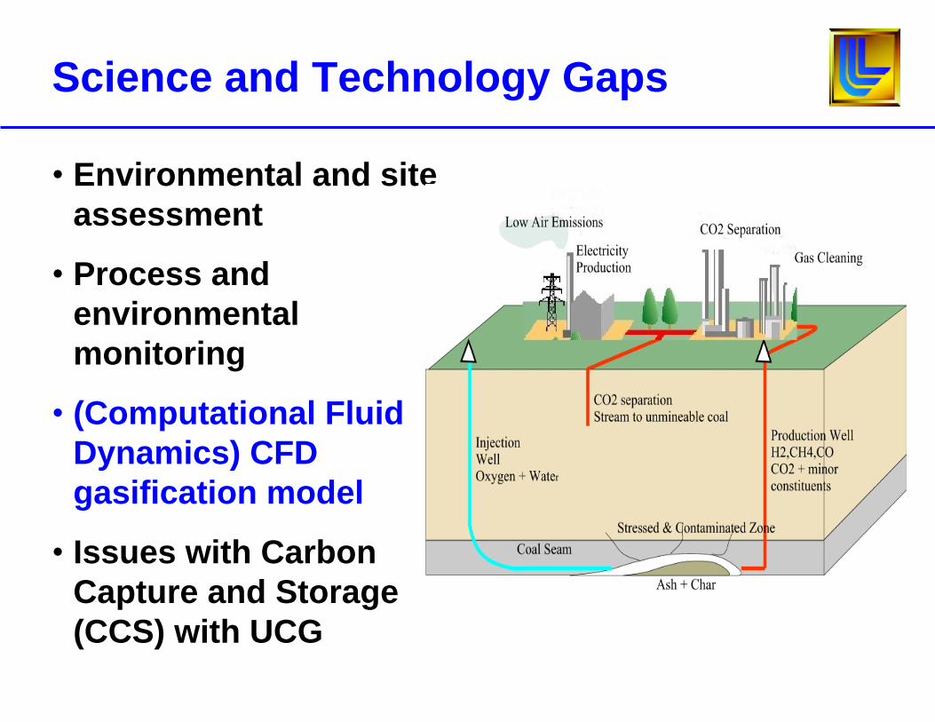
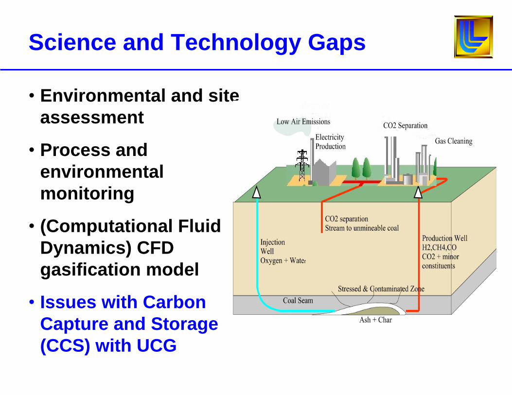
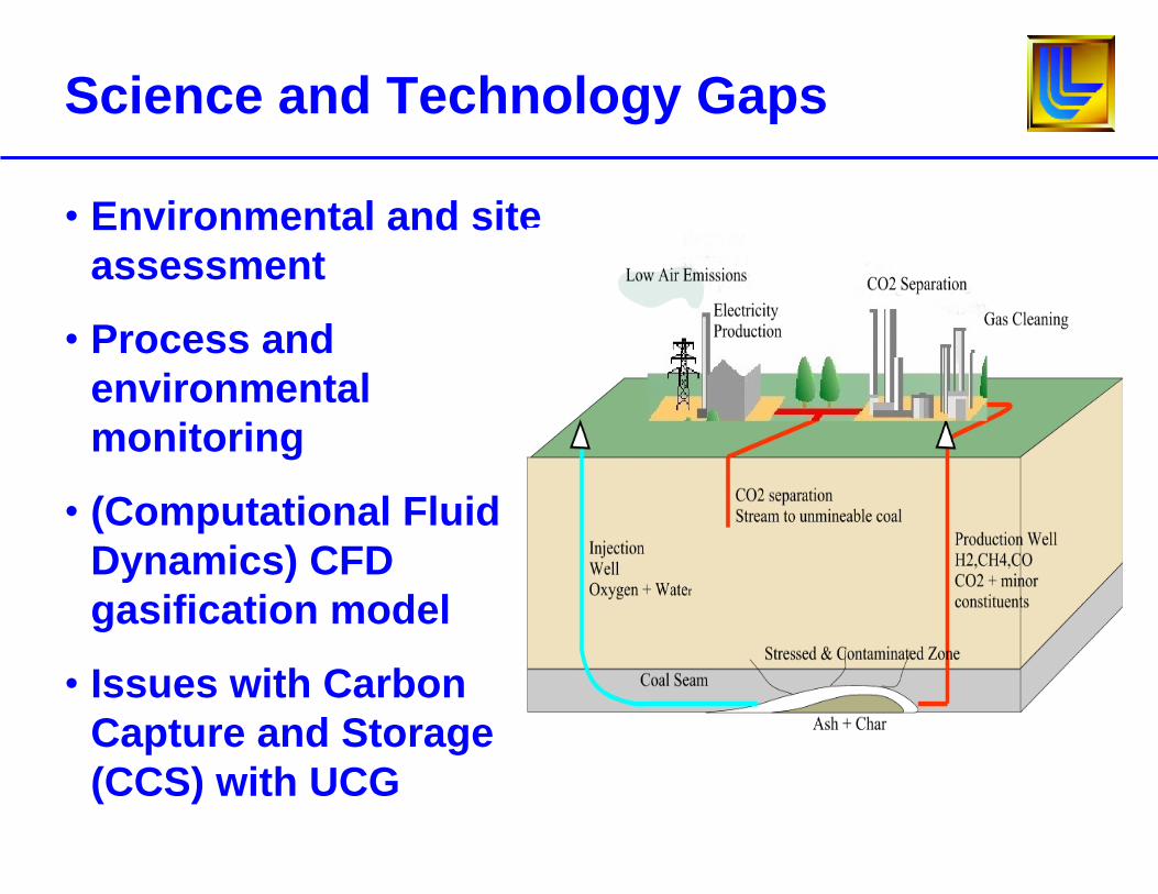
Science and Technology Gaps
• Environmental and site assessment
• Process and environmental monitoring
• (Computational Fluid Dynamics) CFD gasification model
• Issues with Carbon Capture and Storage (CCS) with UCG
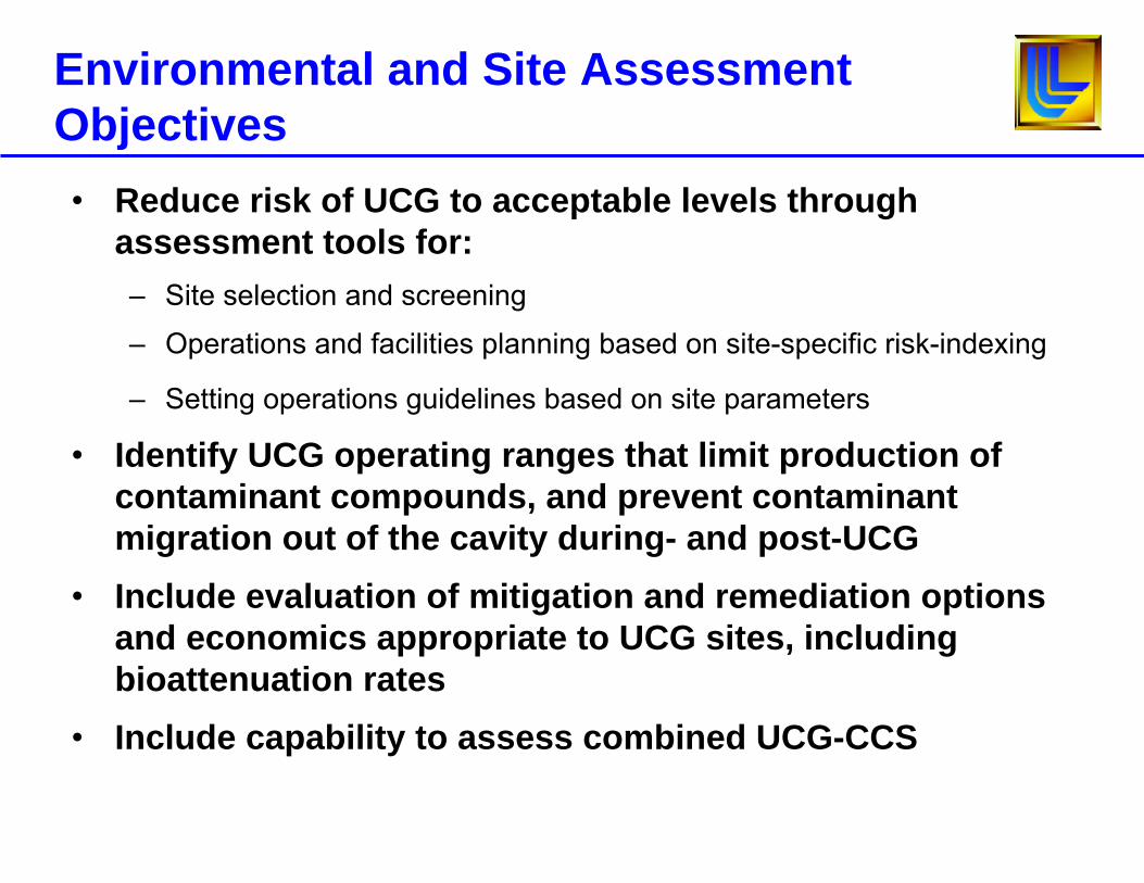
Environmental and Site Assessment Objectives• Reduce risk of UCG to acceptable levels through
assessment tools for:– Site selection and screening
– Operations and facilities planning based on site-specific risk-indexing
– Setting operations guidelines based on site parameters
• Identify UCG operating ranges that limit production of contaminant compounds, and prevent contaminant migration out of the cavity during- and post-UCG
• Include evaluation of mitigation and remediation options and economics appropriate to UCG sites, including bioattenuation rates
• Include capability to assess combined UCG-CCS
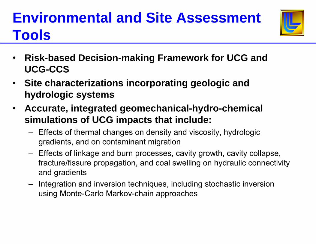
Environmental and Site Assessment Tools• Risk-based Decision-making Framework for UCG and
UCG-CCS• Site characterizations incorporating geologic and
hydrologic systems • Accurate, integrated geomechanical-hydro-chemical
simulations of UCG impacts that include:– Effects of thermal changes on density and viscosity, hydrologic
gradients, and on contaminant migration – Effects of linkage and burn processes, cavity growth, cavity collapse,
fracture/fissure propagation, and coal swelling on hydraulic connectivity and gradients
– Integration and inversion techniques, including stochastic inversion using Monte-Carlo Markov-chain approaches
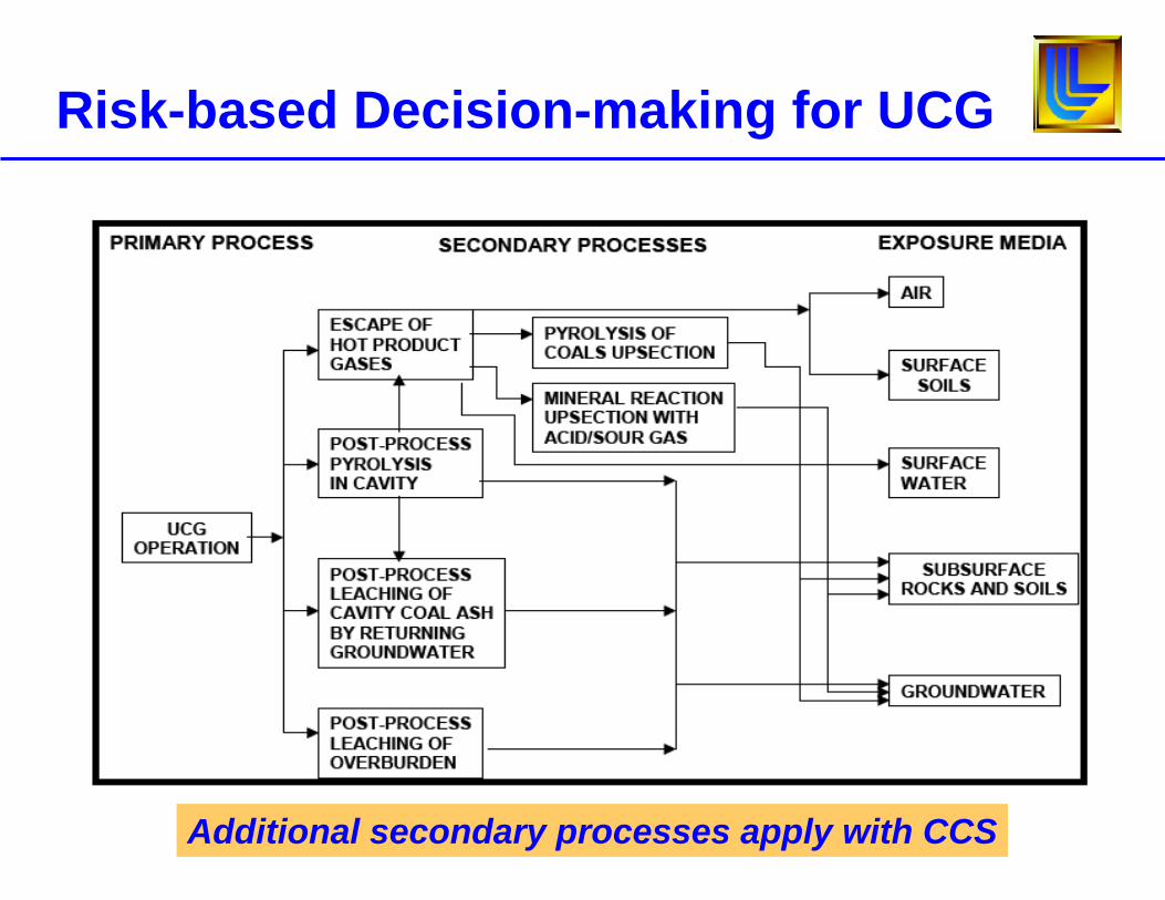
Risk-based Decision-making for UCG
Additional secondary processes apply with CCS
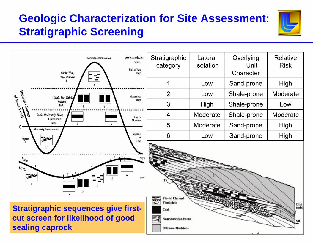
Geologic Characterization for Site Assessment: Stratigraphic Screening
HighSand-proneLow6HighSand-proneModerate5
ModerateShale-proneModerate4LowShale-proneHigh3
ModerateShale-proneLow2HighSand-proneLow1
RelativeRisk
Overlying Unit
Character
LateralIsolation
Stratigraphiccategory
Stratigraphic sequences give first-cut screen for likelihood of good sealing caprock
• UCG environmental assessment cannot be done with a standard toolbox of environmental tools
• UCG requires use of coupled process, hydrological, geochemical and geomechanical models to capture: – Balancing gasifier operational pressure against hydrologic pressure
and other gradients in the field to prevent outward contaminant migration
– Impact of gasifier operating conditions on creation and behavior of contaminants within the burn chamber
– Enhanced vertical hydraulic conductivity of the rock matrix above the burn chamber as a result of collapse and fracturing
– Buoyancy-driven upward flow of groundwater in the vicinity of the burn chamber toward potable water resources at shallower depths
Simulations of UCG Impacts on Geologic-Hydrologic Systems
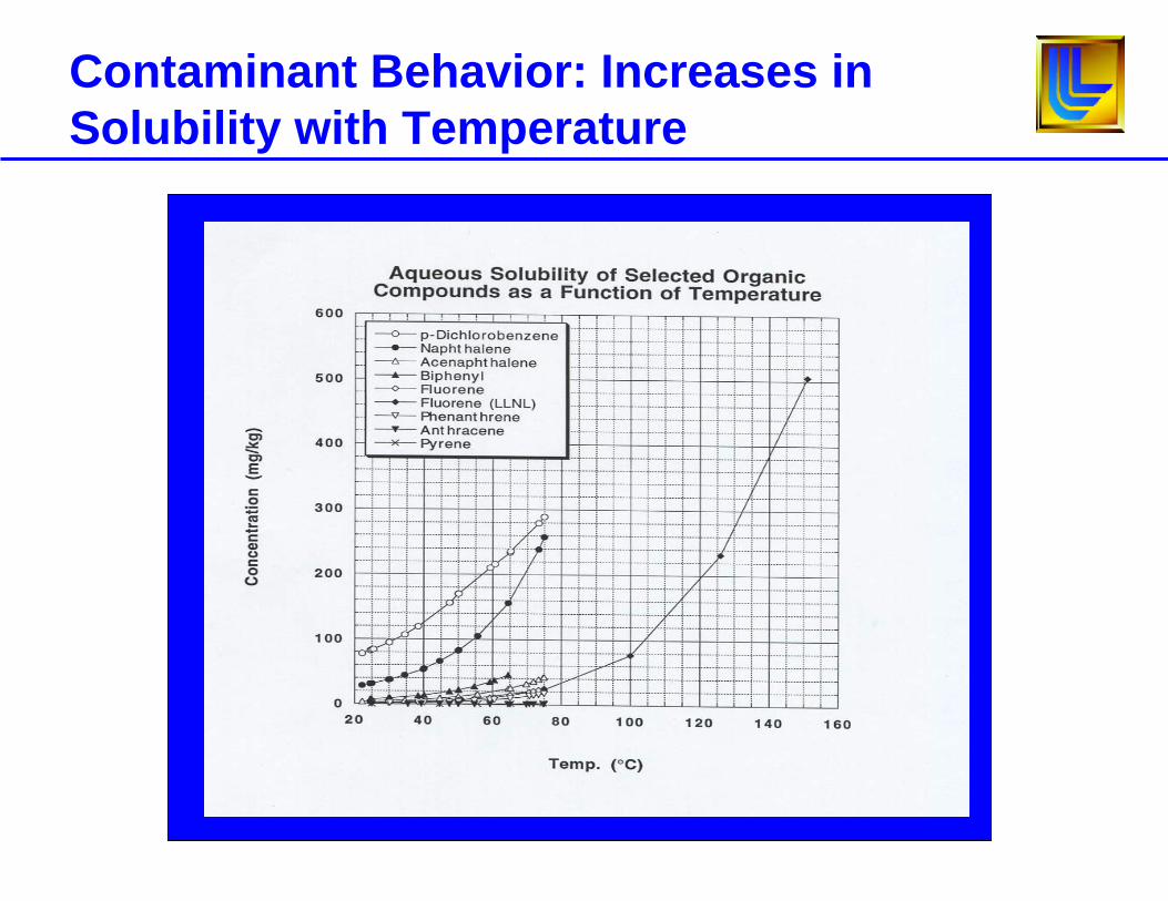
Contaminant Behavior: Increases in Solubility with Temperature
Science and Technology Gaps
• Environmental and site assessment
• Process and environmental monitoring
• (Computational Fluid Dynamics) CFD gasification model
• Issues with Carbon Capture and Storage (CCS) with UCG
Monitoring Objectives
• Real-time insight into potential hazards (subsidence, groundwater contamination) as the UCG burn progresses through the coal seam
• Validate models and improve understanding of the UCG process
• Improve understanding of the geomechanical, geochemical, and hydrogeological changes induced by UCG
• Allow for the possibility of real-time process control of the UCG “reactor”
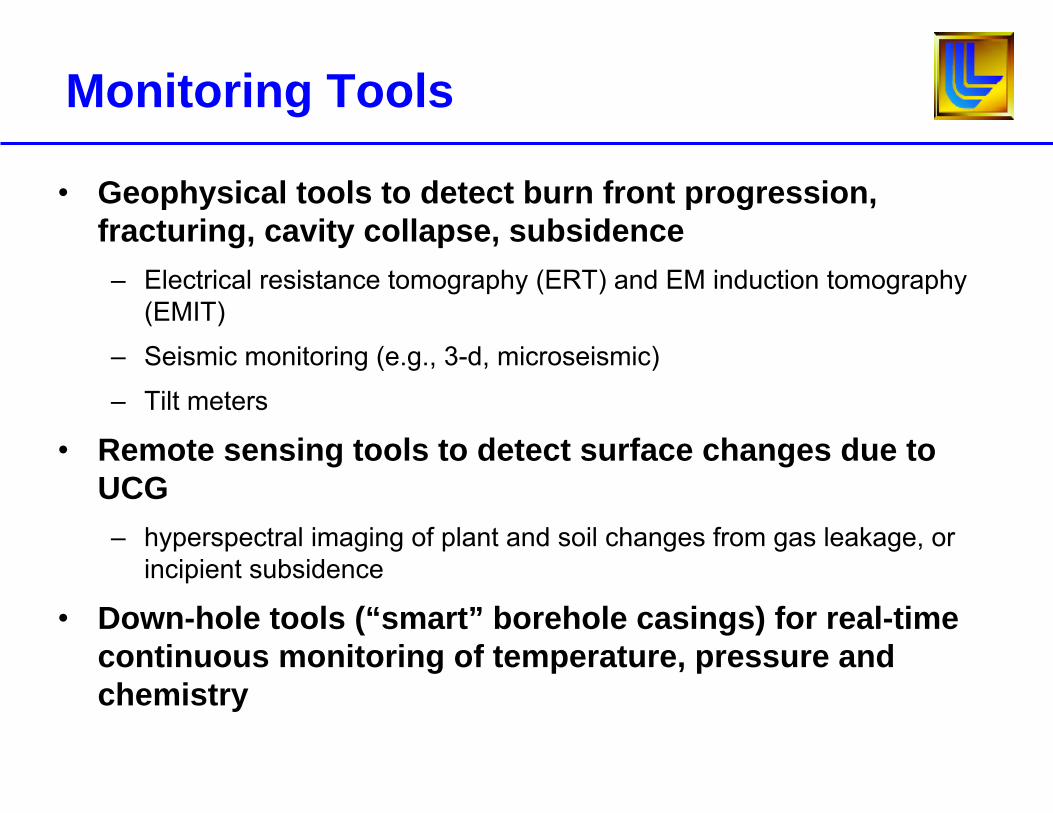
Monitoring Tools
• Geophysical tools to detect burn front progression, fracturing, cavity collapse, subsidence– Electrical resistance tomography (ERT) and EM induction tomography
(EMIT)
– Seismic monitoring (e.g., 3-d, microseismic)
– Tilt meters
• Remote sensing tools to detect surface changes due to UCG– hyperspectral imaging of plant and soil changes from gas leakage, or
incipient subsidence
• Down-hole tools (“smart” borehole casings) for real-time continuous monitoring of temperature, pressure and chemistry
Science and Technology Gaps
• Environmental and site assessment
• Process and environmental monitoring
• (Computational Fluid Dynamics) CFD gasification model
• Issues with Carbon Capture and Storage (CCS) with UCG
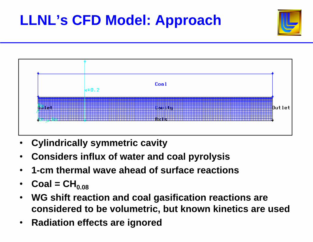
LLNL’s CFD Model: Approach
• Cylindrically symmetric cavity• Considers influx of water and coal pyrolysis• 1-cm thermal wave ahead of surface reactions• Coal = CH0.08
• WG shift reaction and coal gasification reactions are considered to be volumetric, but known kinetics are used
• Radiation effects are ignored
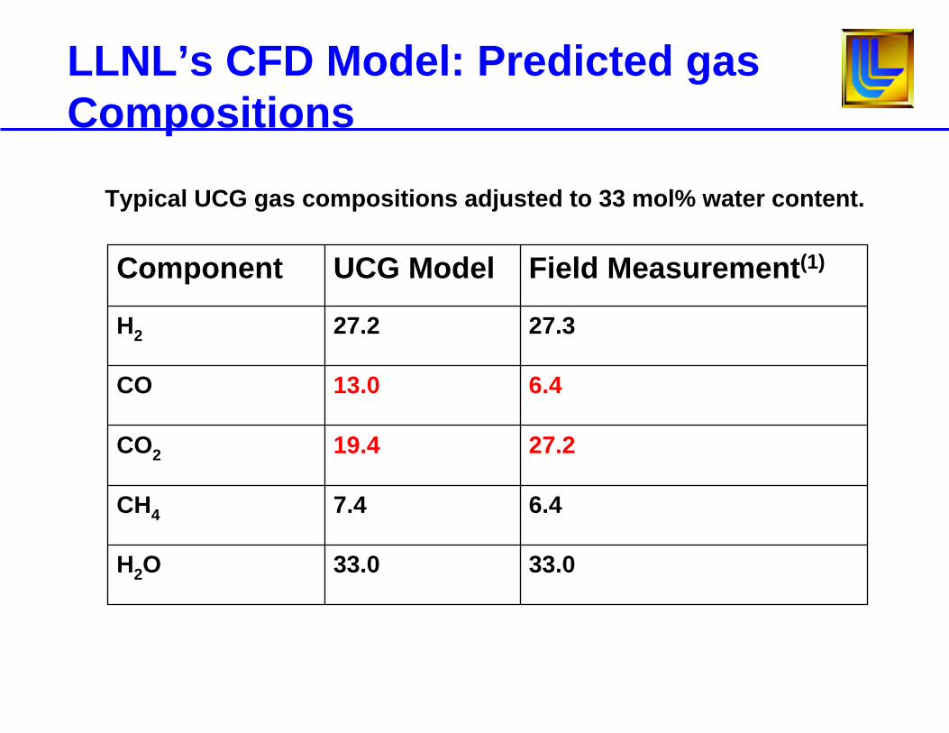
LLNL’s CFD Model: Predicted gas Compositions
Typical UCG gas compositions adjusted to 33 mol% water content.
33.033.0H2O
6.47.4CH4
27.219.4CO2
6.413.0CO
27.327.2H2
Field Measurement(1)UCG ModelComponent
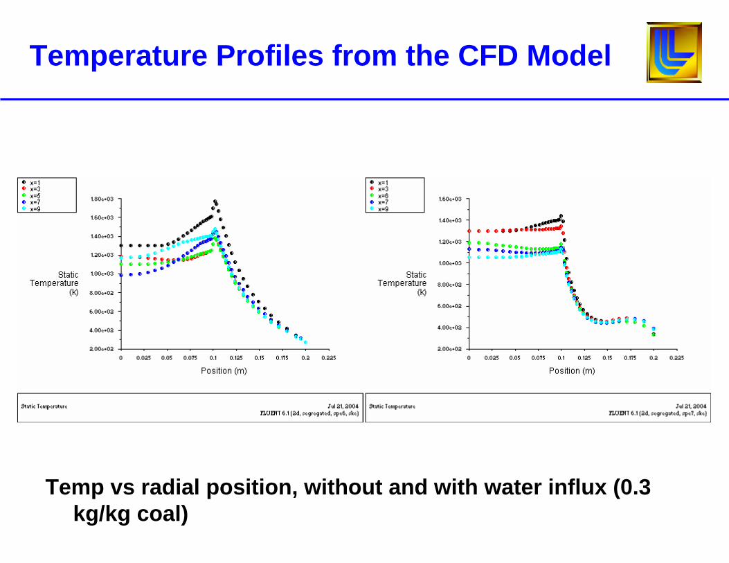
Temperature Profiles from the CFD Model
Temp vs radial position, without and with water influx (0.3 kg/kg coal)
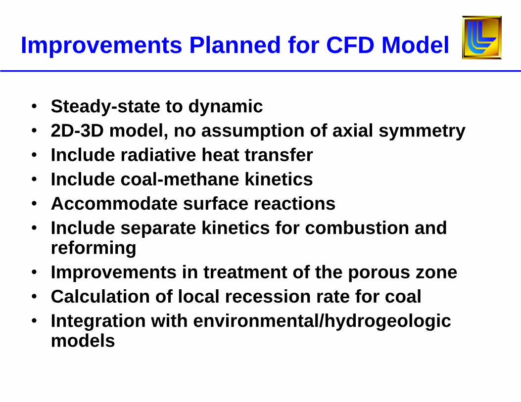
Improvements Planned for CFD Model
• Steady-state to dynamic• 2D-3D model, no assumption of axial symmetry• Include radiative heat transfer• Include coal-methane kinetics• Accommodate surface reactions• Include separate kinetics for combustion and
reforming• Improvements in treatment of the porous zone• Calculation of local recession rate for coal• Integration with environmental/hydrogeologic
models
Science and Technology Gaps
• Environmental and site assessment
• Process and environmental monitoring
• (Computational Fluid Dynamics) CFD gasification model
• Issues with Carbon Capture and Storage (CCS) with UCG
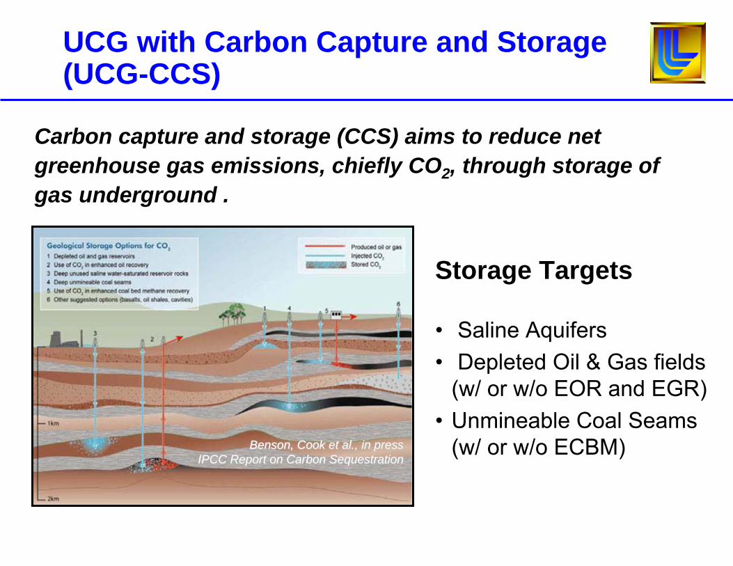
UCG with Carbon Capture and Storage (UCG-CCS)
Benson, Cook et al., in pressBenson, Cook et al., in pressIPCC Report on Carbon SequestrationIPCC Report on Carbon Sequestration
Storage Targets
• Saline Aquifers• Depleted Oil & Gas fields
(w/ or w/o EOR and EGR)• Unmineable Coal Seams
(w/ or w/o ECBM)
Carbon capture and storage (CCS) aims to reduce net greenhouse gas emissions, chiefly CO2, through storage of gas underground .
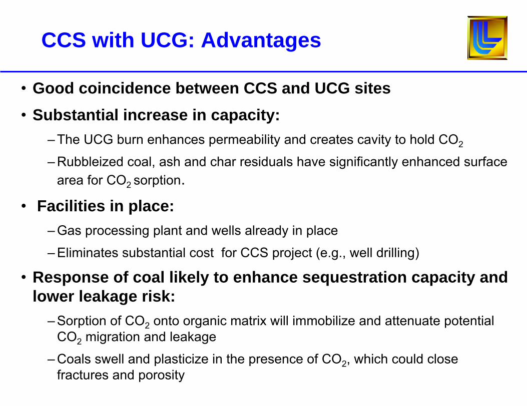
CCS with UCG: Advantages
• Good coincidence between CCS and UCG sites• Substantial increase in capacity:
– The UCG burn enhances permeability and creates cavity to hold CO2
– Rubbleized coal, ash and char residuals have significantly enhanced surface area for CO2 sorption.
• Facilities in place: – Gas processing plant and wells already in place
– Eliminates substantial cost for CCS project (e.g., well drilling)
• Response of coal likely to enhance sequestration capacity and lower leakage risk:
– Sorption of CO2 onto organic matrix will immobilize and attenuate potential CO2 migration and leakage
– Coals swell and plasticize in the presence of CO2, which could close fractures and porosity
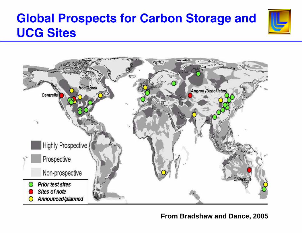
Global Prospects for Carbon Storage and UCG Sites
From Bradshaw and Dance, 2005
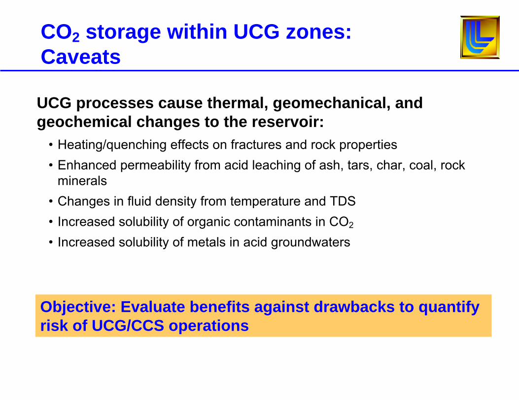
UCG processes cause thermal, geomechanical, and geochemical changes to the reservoir:
• Heating/quenching effects on fractures and rock properties• Enhanced permeability from acid leaching of ash, tars, char, coal, rock
minerals• Changes in fluid density from temperature and TDS• Increased solubility of organic contaminants in CO2
• Increased solubility of metals in acid groundwaters
CO2 storage within UCG zones: Caveats
Objective: Evaluate benefits against drawbacks to quantify risk of UCG/CCS operations
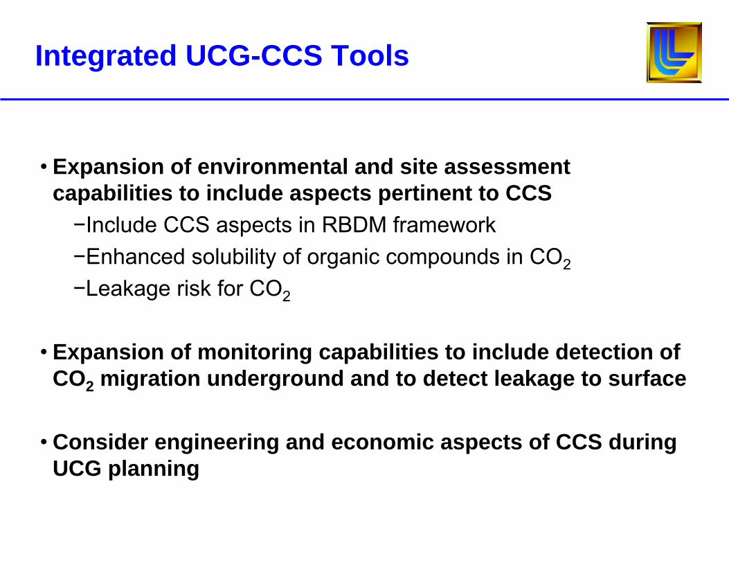
Integrated UCG-CCS Tools
• Expansion of environmental and site assessment capabilities to include aspects pertinent to CCS−Include CCS aspects in RBDM framework−Enhanced solubility of organic compounds in CO2
−Leakage risk for CO2
• Expansion of monitoring capabilities to include detection of CO2 migration underground and to detect leakage to surface
• Consider engineering and economic aspects of CCS during UCG planning
Science and Technology Gaps
• Environmental and site assessment
• Process and environmental monitoring
• (Computational Fluid Dynamics) CFD gasification model
• Issues with Carbon Capture and Storage (CCS) with UCG
Disclaimer and Auspices Statements
This document was prepared as an account of work sponsored by an agency of the United States Government. Neither the United States Government nor the University of California nor any of their employees, makes any warranty, express or implied, or assumes any legal liability or responsibility for the accuracy, completeness, or usefulness of any information, apparatus, product, or process disclosed, or represents that its use would not infringe privately owned rights. Reference herein to any specific commercial product, process, or service by trade name, trademark, manufacturer, or otherwise, does not necessarily constitute or imply its endorsement, recommendation, or favoring by the United States Government or the University of California. The views and opinions of authors expressed herein do not necessarily state or reflect those of the United States Government or the University of California, and shall not be used for advertising or product endorsement purposes.
This work was performed under the auspices of the U.S. Department of Energy by University of California, Lawrence Livermore National Laboratory under Contract W-7405-Eng-48.